Embed Size (px)
Citation preview

Modeling with 2-D Elements Tutorial
Weldment Model
Part Number 4350.501
Revision 19.000
December 2005
Modeling with 2-D Elements Tutorial, Revision 19.000—printed locally from files supplied electronically. 2
December 20, 2005 ALGOR, Inc. 150 Beta Drive Pittsburgh, PA 15238-2932 USA Phone: 1.412.967.2700 USA/Canada: 1.800.48.ALGOR Fax: 1.412.967.2781 Product/Services e-mail: [email protected] Technical Support e-mail: [email protected] Internet Address: www.ALGOR.com
Copyright © 2005 ALGOR, Inc. All rights reserved. This publication may not be reproduced in any form, by any method, for any purpose, either in part or in its entirety, without the expressed written permission of ALGOR, Inc. This publication describes the state of ALGOR software at the time of its printing and may not reflect the software at all times in the future. This publication may be changed without notice. This publication is not designed to transmit any engineering knowledge relating specifically to any company or individual engineering project. In providing this publication, ALGOR does not assume the role of engineering consultant to any user of this publication and hereby disclaims any and all responsibility for any errors or omissions arising out of any engineering activity in which this publication may be utilized. This document has been designed to be printed on the customer's local computer and printer. ALGOR cannot be held responsible for any errors incurred in the printing of this document.
Modeling with 2-D Elements Tutorial, Revision 19.000—printed locally from files supplied electronically. 3
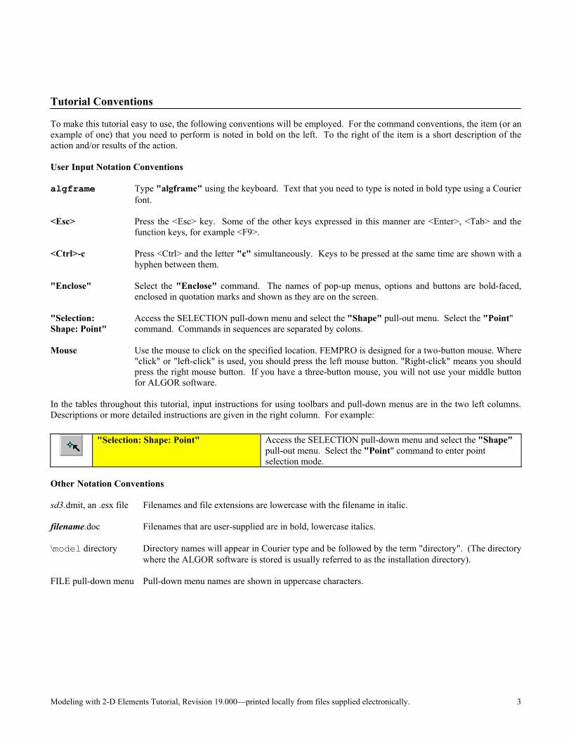
Tutorial Conventions To make this tutorial easy to use, the following conventions will be employed. For the command conventions, the item (or an example of one) that you need to perform is noted in bold on the left. To the right of the item is a short description of the action and/or results of the action. User Input Notation Conventions algframe Type "algframe" using the keyboard. Text that you need to type is noted in bold type using a Courier
font. <Esc> Press the <Esc> key. Some of the other keys expressed in this manner are <Enter>, <Tab> and the
function keys, for example <F9>. <Ctrl>-c Press <Ctrl> and the letter "c" simultaneously. Keys to be pressed at the same time are shown with a
hyphen between them. "Enclose" Select the "Enclose" command. The names of pop-up menus, options and buttons are bold-faced,
enclosed in quotation marks and shown as they are on the screen. "Selection: Access the SELECTION pull-down menu and select the "Shape" pull-out menu. Select the "Point" Shape: Point" command. Commands in sequences are separated by colons. Mouse Use the mouse to click on the specified location. FEMPRO is designed for a two-button mouse. Where
"click" or "left-click" is used, you should press the left mouse button. "Right-click" means you should press the right mouse button. If you have a three-button mouse, you will not use your middle button for ALGOR software.
In the tables throughout this tutorial, input instructions for using toolbars and pull-down menus are in the two left columns. Descriptions or more detailed instructions are given in the right column. For example:
"Selection: Shape: Point" Access the SELECTION pull-down menu and select the "Shape"
pull-out menu. Select the "Point" command to enter point selection mode.
Other Notation Conventions sd3.dmit, an .esx file Filenames and file extensions are lowercase with the filename in italic. filename.doc Filenames that are user-supplied are in bold, lowercase italics. \model directory Directory names will appear in Courier type and be followed by the term "directory". (The directory
where the ALGOR software is stored is usually referred to as the installation directory). FILE pull-down menu Pull-down menu names are shown in uppercase characters.
Modeling with 2-D Elements Tutorial, Revision 19.000—printed locally from files supplied electronically. 4
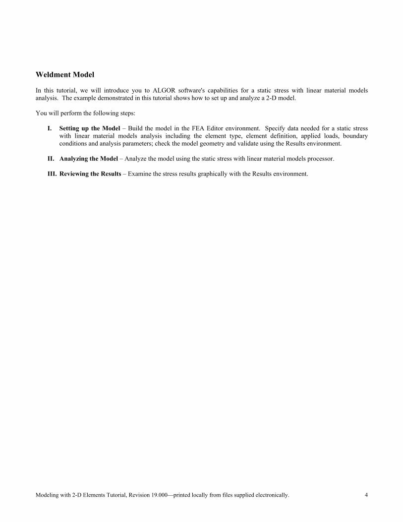
Weldment Model In this tutorial, we will introduce you to ALGOR software's capabilities for a static stress with linear material models analysis. The example demonstrated in this tutorial shows how to set up and analyze a 2-D model. You will perform the following steps:
I. Setting up the Model – Build the model in the FEA Editor environment. Specify data needed for a static stress with linear material models analysis including the element type, element definition, applied loads, boundary conditions and analysis parameters; check the model geometry and validate using the Results environment.
II. Analyzing the Model – Analyze the model using the static stress with linear material models processor.
III. Reviewing the Results – Examine the stress results graphically with the Results environment.
Modeling with 2-D Elements Tutorial, Revision 19.000—printed locally from files supplied electronically. 5
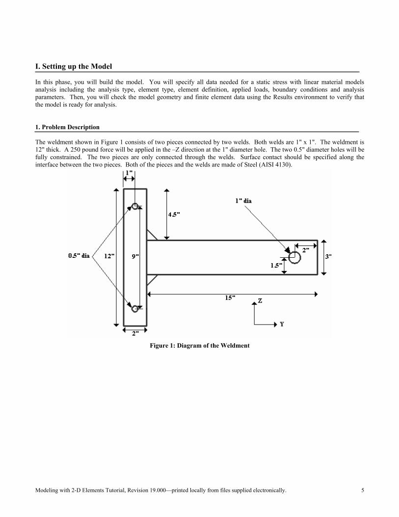
I. Setting up the Model In this phase, you will build the model. You will specify all data needed for a static stress with linear material models analysis including the analysis type, element type, element definition, applied loads, boundary conditions and analysis parameters. Then, you will check the model geometry and finite element data using the Results environment to verify that the model is ready for analysis. 1. Problem Description The weldment shown in Figure 1 consists of two pieces connected by two welds. Both welds are 1" x 1". The weldment is 12" thick. A 250 pound force will be applied in the –Z direction at the 1" diameter hole. The two 0.5" diameter holes will be fully constrained. The two pieces are only connected through the welds. Surface contact should be specified along the interface between the two pieces. Both of the pieces and the welds are made of Steel (AISI 4130).
Figure 1: Diagram of the Weldment
Modeling with 2-D Elements Tutorial, Revision 19.000—printed locally from files supplied electronically. 6
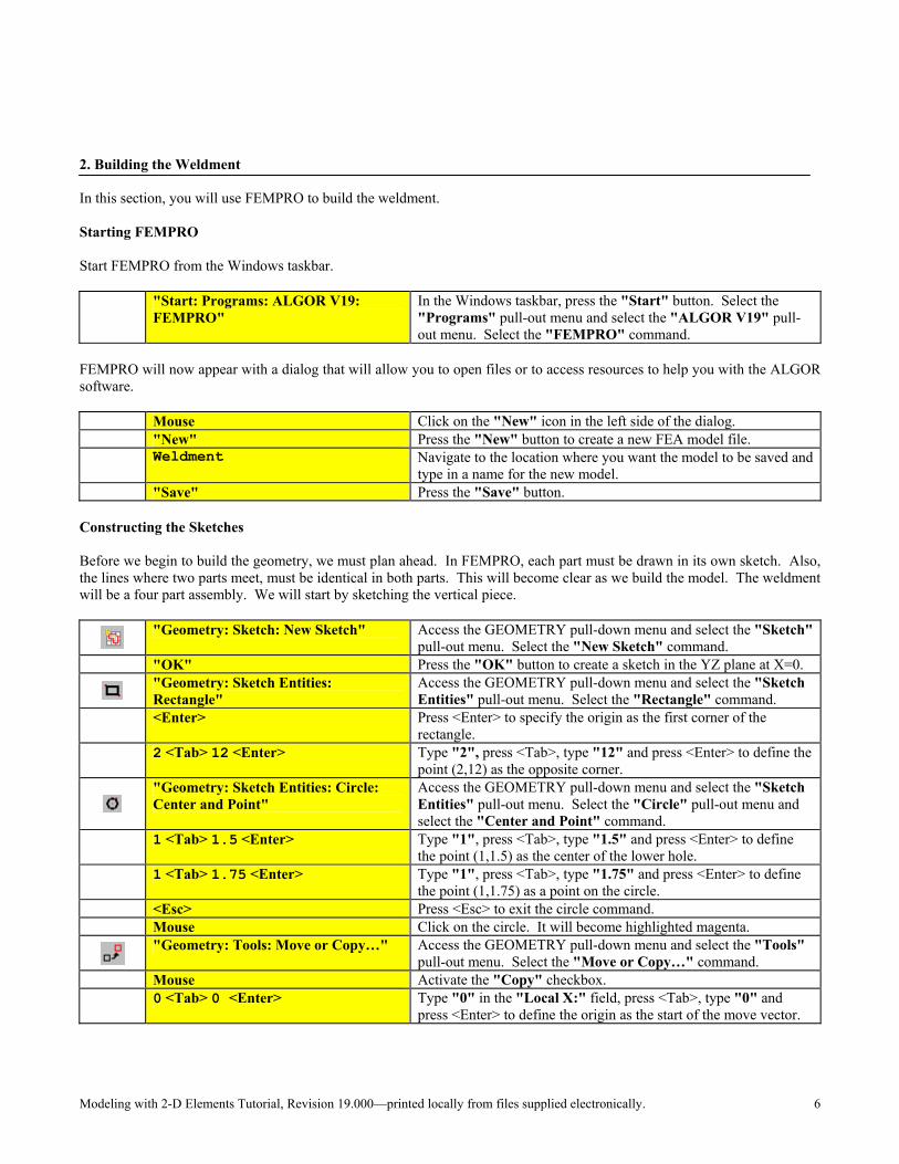
2. Building the Weldment In this section, you will use FEMPRO to build the weldment. Starting FEMPRO Start FEMPRO from the Windows taskbar.
"Start: Programs: ALGOR V19: FEMPRO"
In the Windows taskbar, press the "Start" button. Select the "Programs" pull-out menu and select the "ALGOR V19" pull-out menu. Select the "FEMPRO" command.
FEMPRO will now appear with a dialog that will allow you to open files or to access resources to help you with the ALGOR software.
Mouse Click on the "New" icon in the left side of the dialog. "New" Press the "New" button to create a new FEA model file.
Weldment Navigate to the location where you want the model to be saved and
type in a name for the new model. "Save" Press the "Save" button.
Constructing the Sketches Before we begin to build the geometry, we must plan ahead. In FEMPRO, each part must be drawn in its own sketch. Also, the lines where two parts meet, must be identical in both parts. This will become clear as we build the model. The weldment will be a four part assembly. We will start by sketching the vertical piece.
"Geometry: Sketch: New Sketch" Access the GEOMETRY pull-down menu and select the "Sketch"
pull-out menu. Select the "New Sketch" command. "OK" Press the "OK" button to create a sketch in the YZ plane at X=0.
"Geometry: Sketch Entities: Rectangle"
Access the GEOMETRY pull-down menu and select the "Sketch Entities" pull-out menu. Select the "Rectangle" command.
<Enter> Press <Enter> to specify the origin as the first corner of the rectangle.
2 <Tab> 12 <Enter> Type "2", press <Tab>, type "12" and press <Enter> to define the point (2,12) as the opposite corner.
"Geometry: Sketch Entities: Circle: Center and Point"
Access the GEOMETRY pull-down menu and select the "Sketch Entities" pull-out menu. Select the "Circle" pull-out menu and select the "Center and Point" command.
1 <Tab> 1.5 <Enter> Type "1", press <Tab>, type "1.5" and press <Enter> to define the point (1,1.5) as the center of the lower hole.
1 <Tab> 1.75 <Enter> Type "1", press <Tab>, type "1.75" and press <Enter> to define the point (1,1.75) as a point on the circle.
<Esc> Press <Esc> to exit the circle command. Mouse Click on the circle. It will become highlighted magenta.
"Geometry: Tools: Move or Copy…" Access the GEOMETRY pull-down menu and select the "Tools"
pull-out menu. Select the "Move or Copy…" command. Mouse Activate the "Copy" checkbox.
0 <Tab> 0 <Enter> Type "0" in the "Local X:" field, press <Tab>, type "0" and press <Enter> to define the origin as the start of the move vector.

Modeling with 2-D Elements Tutorial, Revision 19.000—printed locally from files supplied electronically. 7
9 <Enter> Type "9" and press <Enter> to define the point (0,9) as the start of the move vector. A copy of the circle will be created.
"Geometry: Sketch: Finish Sketch" Access the GEOMETRY pull-down menu and select the "Sketch" pull-out menu. Select the "Finish Sketch" command. We will have to edit this sketch at a later point to get the proper divisions, but we are done for now.
Now we will draw the horizontal piece.
"Geometry: Sketch: New Sketch" Access the GEOMETRY pull-down menu and select the "Sketch" pull-out menu. Select the "New Sketch" command. The rectangle from the previous sketch will appear as a ghost image. You can select points on this sketch to use as reference. You cannot select any entities in other sketches.
"OK" Press the "OK" button.
"Geometry: Sketch Entities: Rectangle"
Access the GEOMETRY pull-down menu and select the "Sketch Entities" pull-out menu. Select the "Rectangle" command.
2 <Tab> 4.5 <Enter> Type "2", press <Tab>, type "4.5" and press <Enter> to define the point (2,4.5) as the first corner.
17 <Tab> 7.5 <Enter> Type "17", press <Tab>, type "7.5" and press <Enter> to define the point (17,7.5) as the opposite corner.
"Geometry: Sketch Entities: Circle: Center and Point"
Access the GEOMETRY pull-down menu and select the "Sketch Entities" pull-out menu. Select the "Circle" pull-out menu and select the "Center and Point" command.
15 <Tab> 6 <Enter> Type "15", press <Tab>, type "6" and press <Enter> to define the point (15,6) as the center of the lower hole.
15 <Tab> 6.5 <Enter> Type "15", press <Tab>, type "6.5" and press <Enter> to define the point (15,6.5) as a point on the circle.
<Esc> Press <Esc> to exit the circle command.
"View: Enclose" Access the VIEW pull-down menu and select the "Enclose"
command to view the entire model in the display area. The two horizontal lines of the rectangle in Sketch 2 will be used to intersect the rectangle in Sketch 1 so that the line where the two sketches meet is identical in both sketches. We can copy these lines into Sketch 1 to perform the intersection.
Mouse Click on the top horizontal line. <Ctrl> Mouse Holding down the <Ctrl> key, click on the bottom horizontal line.
"Edit: Copy" Access the EDIT pull-down menu and select the "Copy"
command. The selected entities will be copied to the clipboard.
"Geometry: Sketch: Finish Sketch" Access the GEOMETRY pull-down menu and select the "Sketch" pull-out menu. Select the "Finish Sketch" command. We will have to edit this sketch at a later point as well to get the proper divisions, but we are done for now.
Mouse Right click on the "Sketch 1" heading in the tree view.
"Modify" Select the "Modify" command. Sketch 1 will now be the current sketch.

Modeling with 2-D Elements Tutorial, Revision 19.000—printed locally from files supplied electronically. 8
"Edit: Paste" Access the EDIT pull-down menu and select the "Paste"
command. The two horizontal lines will now appear in Sketch 1.
"Geometry: Tools: Intersect" Access the GEOMETRY pull-down menu and select the "Tools"
pull-out menu. Select the "Intersect" command.
Mouse Click on the top horizontal line that was copied from Sketch 2. This will be the entity that is used to create the intersection.
Mouse Click on the right vertical line. This will be the entity that will be intersected.
<Enter> Press <Enter>. The intersection will be performed. Now the right vertical line is broken into two lines.
Mouse Click on the bottom horizontal line that was copied from Sketch 2. This will be the entity that is used to create the intersection.
Mouse Click on the lower right vertical line. This will be the entity that will be intersected.
<Enter> Press <Enter>. The intersection will be performed. Now the right
vertical line will consist of three segments. This is necessary because the center segment now matches the segment in Sketch 2.
<Esc> Press <Esc> to exit the intersect command. Mouse Click on the top horizontal line from Sketch 2.
<Ctrl> Mouse Holding down the <Ctrl> key, click on the bottom horizontal line from Sketch 2.
"Edit: Delete" Access the EDIT pull-down menu and select the "Delete"
command. The selected entities will be deleted from Sketch 1. They still exist in Sketch 2.
"Geometry: Sketch: Finish Sketch" Access the GEOMETRY pull-down menu and select the "Sketch" pull-out menu. Select the "Finish Sketch" command. We will have to edit this sketch at a later point to get the proper divisions, but we are done for now.
We will now construct the two weld sketches.
"Geometry: Sketch: New Sketch" Access the GEOMETRY pull-down menu and select the "Sketch"
pull-out menu. Select the "New Sketch" command "OK" Press the "OK" button.
"Geometry: Sketch Entities: Line" Access the GEOMETRY pull-down menu and select the "Sketch
Entities" pull-out menu. Select the "Line" command. Mouse Activate the "Use Relative" checkbox.
Mouse Click on the upper point where the first two sketches meet as
shown in Figure 2. A yellow square will appear over the point when the cursor is close enough.

Modeling with 2-D Elements Tutorial, Revision 19.000—printed locally from files supplied electronically. 9
Figure 2: Select the Upper Point Where the First Two Sketches Meet
<Tab> 1 <Enter> Press <Tab>, type "1" in the "Local DY:" field and press
<Enter> to define a point 1 inch in the local Y direction from the current point.
1 <Tab> -1 <Enter> Type "1", press <Tab>, type "-1" and press <Enter> to define a
point 1 inch in the local X direction and 1 inch in the local –Y direction from the current point.
-1 <Enter> Type "-1" and press <Enter> to define a point 1 inch in the local -X direction from the current point.
<Esc> Press <Esc> to exit the line command.
"Geometry: Sketch Entities: Center Line"
Access the GEOMETRY pull-down menu and select the "Sketch Entities" pull-out menu. Select the "Center Line" command.
Mouse Deactivate the "Use Relative" checkbox.
Mouse Click on any grid point on the local Y=6 line. This is the vertical
centerline of the model. When you are adequately close to a grid point a yellow square will appear.
Mouse Click on any other grid point on the local Y=6 line. A
construction line colored gray will appear. The screen should look like Figure 3.
Figure 3: Sketch 3 with a Weld and a Center Line
Modeling with 2-D Elements Tutorial, Revision 19.000—printed locally from files supplied electronically. 10
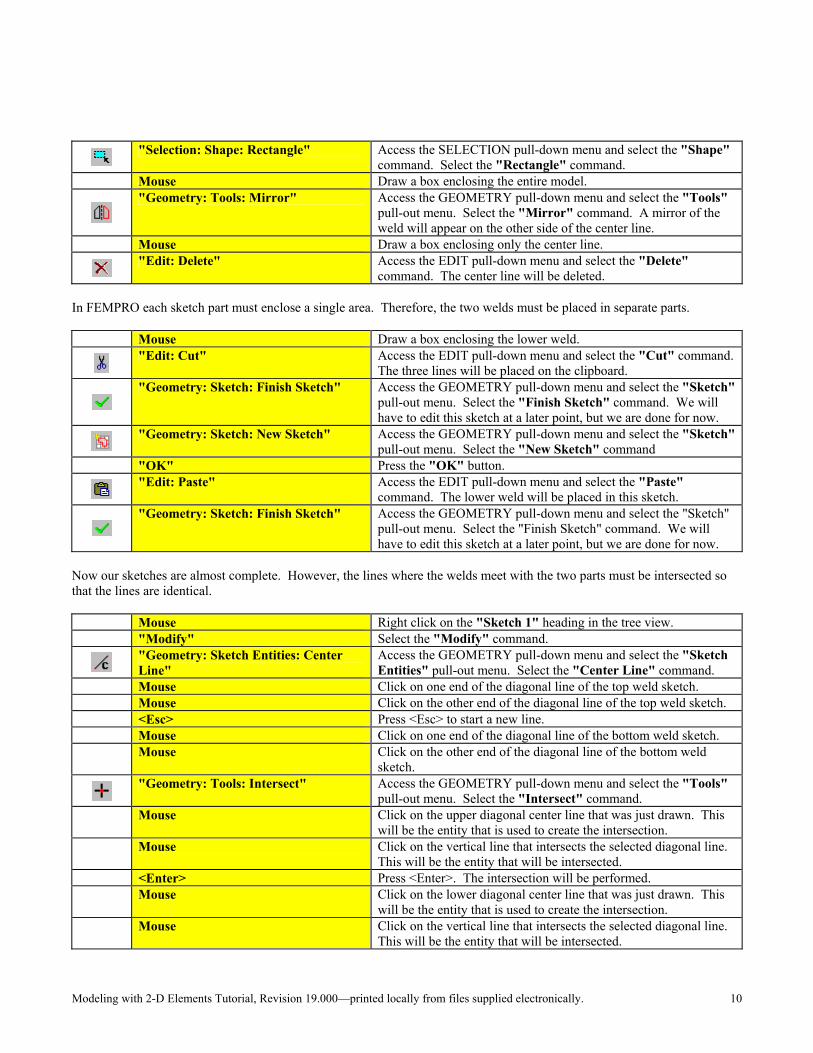
"Selection: Shape: Rectangle" Access the SELECTION pull-down menu and select the "Shape"
command. Select the "Rectangle" command. Mouse Draw a box enclosing the entire model.
"Geometry: Tools: Mirror" Access the GEOMETRY pull-down menu and select the "Tools"
pull-out menu. Select the "Mirror" command. A mirror of the weld will appear on the other side of the center line.
Mouse Draw a box enclosing only the center line.
"Edit: Delete" Access the EDIT pull-down menu and select the "Delete"
command. The center line will be deleted. In FEMPRO each sketch part must enclose a single area. Therefore, the two welds must be placed in separate parts.
Mouse Draw a box enclosing the lower weld.
"Edit: Cut" Access the EDIT pull-down menu and select the "Cut" command.
The three lines will be placed on the clipboard.
"Geometry: Sketch: Finish Sketch" Access the GEOMETRY pull-down menu and select the "Sketch"
pull-out menu. Select the "Finish Sketch" command. We will have to edit this sketch at a later point, but we are done for now.
"Geometry: Sketch: New Sketch" Access the GEOMETRY pull-down menu and select the "Sketch"
pull-out menu. Select the "New Sketch" command "OK" Press the "OK" button.
"Edit: Paste" Access the EDIT pull-down menu and select the "Paste"
command. The lower weld will be placed in this sketch.
"Geometry: Sketch: Finish Sketch" Access the GEOMETRY pull-down menu and select the "Sketch"
pull-out menu. Select the "Finish Sketch" command. We will have to edit this sketch at a later point, but we are done for now.
Now our sketches are almost complete. However, the lines where the welds meet with the two parts must be intersected so that the lines are identical.
Mouse Right click on the "Sketch 1" heading in the tree view. "Modify" Select the "Modify" command.
"Geometry: Sketch Entities: Center Line"
Access the GEOMETRY pull-down menu and select the "Sketch Entities" pull-out menu. Select the "Center Line" command.
Mouse Click on one end of the diagonal line of the top weld sketch. Mouse Click on the other end of the diagonal line of the top weld sketch. <Esc> Press <Esc> to start a new line. Mouse Click on one end of the diagonal line of the bottom weld sketch.
Mouse Click on the other end of the diagonal line of the bottom weld sketch.
"Geometry: Tools: Intersect" Access the GEOMETRY pull-down menu and select the "Tools"
pull-out menu. Select the "Intersect" command.
Mouse Click on the upper diagonal center line that was just drawn. This will be the entity that is used to create the intersection.
Mouse Click on the vertical line that intersects the selected diagonal line. This will be the entity that will be intersected.
<Enter> Press <Enter>. The intersection will be performed.
Mouse Click on the lower diagonal center line that was just drawn. This will be the entity that is used to create the intersection.
Mouse Click on the vertical line that intersects the selected diagonal line. This will be the entity that will be intersected.
Modeling with 2-D Elements Tutorial, Revision 19.000—printed locally from files supplied electronically. 11
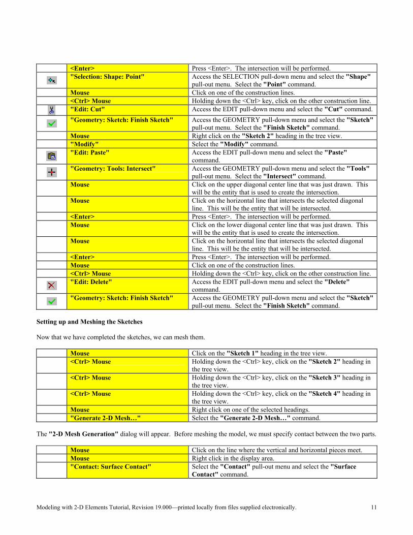
<Enter> Press <Enter>. The intersection will be performed.
"Selection: Shape: Point" Access the SELECTION pull-down menu and select the "Shape"
pull-out menu. Select the "Point" command. Mouse Click on one of the construction lines. <Ctrl> Mouse Holding down the <Ctrl> key, click on the other construction line.
"Edit: Cut" Access the EDIT pull-down menu and select the "Cut" command.
"Geometry: Sketch: Finish Sketch" Access the GEOMETRY pull-down menu and select the "Sketch"
pull-out menu. Select the "Finish Sketch" command. Mouse Right click on the "Sketch 2" heading in the tree view. "Modify" Select the "Modify" command.
"Edit: Paste" Access the EDIT pull-down menu and select the "Paste"
command.
"Geometry: Tools: Intersect" Access the GEOMETRY pull-down menu and select the "Tools"
pull-out menu. Select the "Intersect" command.
Mouse Click on the upper diagonal center line that was just drawn. This will be the entity that is used to create the intersection.
Mouse Click on the horizontal line that intersects the selected diagonal line. This will be the entity that will be intersected.
<Enter> Press <Enter>. The intersection will be performed.
Mouse Click on the lower diagonal center line that was just drawn. This will be the entity that is used to create the intersection.
Mouse Click on the horizontal line that intersects the selected diagonal line. This will be the entity that will be intersected.
<Enter> Press <Enter>. The intersection will be performed. Mouse Click on one of the construction lines. <Ctrl> Mouse Holding down the <Ctrl> key, click on the other construction line.
"Edit: Delete" Access the EDIT pull-down menu and select the "Delete"
command.
"Geometry: Sketch: Finish Sketch" Access the GEOMETRY pull-down menu and select the "Sketch"
pull-out menu. Select the "Finish Sketch" command. Setting up and Meshing the Sketches Now that we have completed the sketches, we can mesh them.
Mouse Click on the "Sketch 1" heading in the tree view.
<Ctrl> Mouse Holding down the <Ctrl> key, click on the "Sketch 2" heading in the tree view.
<Ctrl> Mouse Holding down the <Ctrl> key, click on the "Sketch 3" heading in the tree view.
<Ctrl> Mouse Holding down the <Ctrl> key, click on the "Sketch 4" heading in the tree view.
Mouse Right click on one of the selected headings. "Generate 2-D Mesh…" Select the "Generate 2-D Mesh…" command.
The "2-D Mesh Generation" dialog will appear. Before meshing the model, we must specify contact between the two parts.
Mouse Click on the line where the vertical and horizontal pieces meet. Mouse Right click in the display area.
"Contact: Surface Contact" Select the "Contact" pull-out menu and select the "Surface Contact" command.
Modeling with 2-D Elements Tutorial, Revision 19.000—printed locally from files supplied electronically. 12
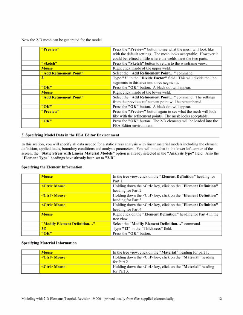
Now the 2-D mesh can be generated for the model.
"Preview" Press the "Preview" button to see what the mesh will look like
with the default settings. The mesh looks acceptable. However it could be refined a little where the welds meet the two parts.
"Sketch" Press the "Sketch" button to return to the wireframe view. Mouse Right click inside of the upper weld. "Add Refinement Point" Select the "Add Refinement Point…" command.
3 Type "3" in the "Divide Factor" field. This will divide the line
segments in this area into three segments. "OK" Press the "OK" button. A black dot will appear. Mouse Right click inside of the lower weld.
"Add Refinement Point" Select the "Add Refinement Point…" command. The settings from the previous refinement point will be remembered.
"OK" Press the "OK" button. A black dot will appear.
"Preview" Press the "Preview" button again to see what the mesh will look like with the refinement points. The mesh looks acceptable.
"OK" Press the "OK" button. The 2-D elements will be loaded into the FEA Editor environment.
3. Specifying Model Data in the FEA Editor Environment In this section, you will specify all data needed for a static stress analysis with linear material models including the element definition, applied loads, boundary conditions and analysis parameters. You will note that in the lower left corner of the screen, the "Static Stress with Linear Material Models" option is already selected in the "Analysis type" field. Also the "Element Type" headings have already been set to "2-D". Specifying the Element Information
Mouse In the tree view, click on the "Element Definition" heading for Part 1.
<Ctrl> Mouse Holding down the <Ctrl> key, click on the "Element Definition" heading for Part 2.
<Ctrl> Mouse Holding down the <Ctrl> key, click on the "Element Definition" heading for Part 3.
<Ctrl> Mouse Holding down the <Ctrl> key, click on the "Element Definition" heading for Part 4.
Mouse Right click on the "Element Definition" heading for Part 4 in the tree view.
"Modify Element Definition…" Select the "Modify Element Definition…" command. 12 Type "12" in the "Thickness" field. "OK" Press the "OK" button.
Specifying Material Information
Mouse In the tree view, click on the "Material" heading for part 1.
<Ctrl> Mouse Holding down the <Ctrl> key, click on the "Material" heading for Part 2.
<Ctrl> Mouse Holding down the <Ctrl> key, click on the "Material" heading for Part 3.

Modeling with 2-D Elements Tutorial, Revision 19.000—printed locally from files supplied electronically. 13
<Ctrl> Mouse Holding down the <Ctrl> key, click on the "Material" heading for Part 4.
Mouse Right click on one of the selected headings.
"Modify Material…" Select the "Modify Material…" command. The "Element Material Selection" dialog will appear.
"Steel (AISI 4130)" Highlight the "Steel AISI (4130)" option in the "Select Material" section. (See Figure 4.)
"OK" Press the "OK" button to accept the material property choice. The selected material will be shown in the tree view.
Figure 4: Element Material Selection Dialog
Constraining the Model Apply nodal boundary conditions
"Selection: Shape: Circle" Access the SELECTION pull-down menu and select the "Shape"
pull-out menu. Select the "Circle" command.
"Selection: Select: Vertices" Access the SELECTION pull-down menu and select the "Select"
pull-out menu. Select the "Vertices" command.
View: Zoom Area" Access the VIEW pull-down menu and select the "Zoom Area"
command. Mouse Draw a box around the upper small hole. <Esc> Press <Esc> to exit zoom mode.
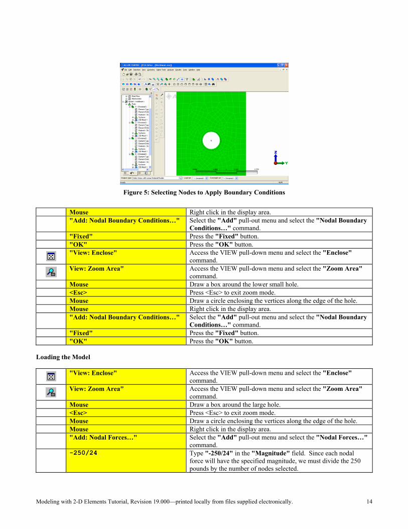
Mouse Draw a circle enclosing the vertices along the edge of the hole as shown in Figure 5.
Modeling with 2-D Elements Tutorial, Revision 19.000—printed locally from files supplied electronically. 14
Figure 5: Selecting Nodes to Apply Boundary Conditions
Mouse Right click in the display area.
"Add: Nodal Boundary Conditions…" Select the "Add" pull-out menu and select the "Nodal Boundary Conditions…" command.
"Fixed" Press the "Fixed" button. "OK" Press the "OK" button.
"View: Enclose" Access the VIEW pull-down menu and select the "Enclose"
command.
View: Zoom Area" Access the VIEW pull-down menu and select the "Zoom Area"
command. Mouse Draw a box around the lower small hole. <Esc> Press <Esc> to exit zoom mode. Mouse Draw a circle enclosing the vertices along the edge of the hole. Mouse Right click in the display area.
"Add: Nodal Boundary Conditions…" Select the "Add" pull-out menu and select the "Nodal Boundary Conditions…" command.
"Fixed" Press the "Fixed" button. "OK" Press the "OK" button.
Loading the Model
"View: Enclose" Access the VIEW pull-down menu and select the "Enclose"
command.
View: Zoom Area" Access the VIEW pull-down menu and select the "Zoom Area"
command. Mouse Draw a box around the large hole. <Esc> Press <Esc> to exit zoom mode. Mouse Draw a circle enclosing the vertices along the edge of the hole. Mouse Right click in the display area.
"Add: Nodal Forces…" Select the "Add" pull-out menu and select the "Nodal Forces…" command.
-250/24 Type "-250/24" in the "Magnitude" field. Since each nodal
force will have the specified magnitude, we must divide the 250 pounds by the number of nodes selected.
Modeling with 2-D Elements Tutorial, Revision 19.000—printed locally from files supplied electronically. 15
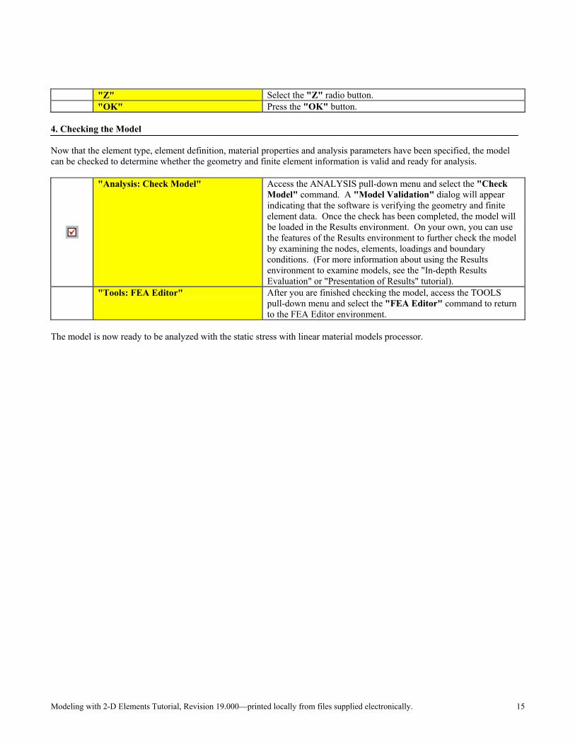
"Z" Select the "Z" radio button. "OK" Press the "OK" button.
4. Checking the Model Now that the element type, element definition, material properties and analysis parameters have been specified, the model can be checked to determine whether the geometry and finite element information is valid and ready for analysis.
"Analysis: Check Model" Access the ANALYSIS pull-down menu and select the "Check Model" command. A "Model Validation" dialog will appear indicating that the software is verifying the geometry and finite element data. Once the check has been completed, the model will be loaded in the Results environment. On your own, you can use the features of the Results environment to further check the model by examining the nodes, elements, loadings and boundary conditions. (For more information about using the Results environment to examine models, see the "In-depth Results Evaluation" or "Presentation of Results" tutorial).
"Tools: FEA Editor" After you are finished checking the model, access the TOOLS
pull-down menu and select the "FEA Editor" command to return to the FEA Editor environment.
The model is now ready to be analyzed with the static stress with linear material models processor.
Modeling with 2-D Elements Tutorial, Revision 19.000—printed locally from files supplied electronically. 16
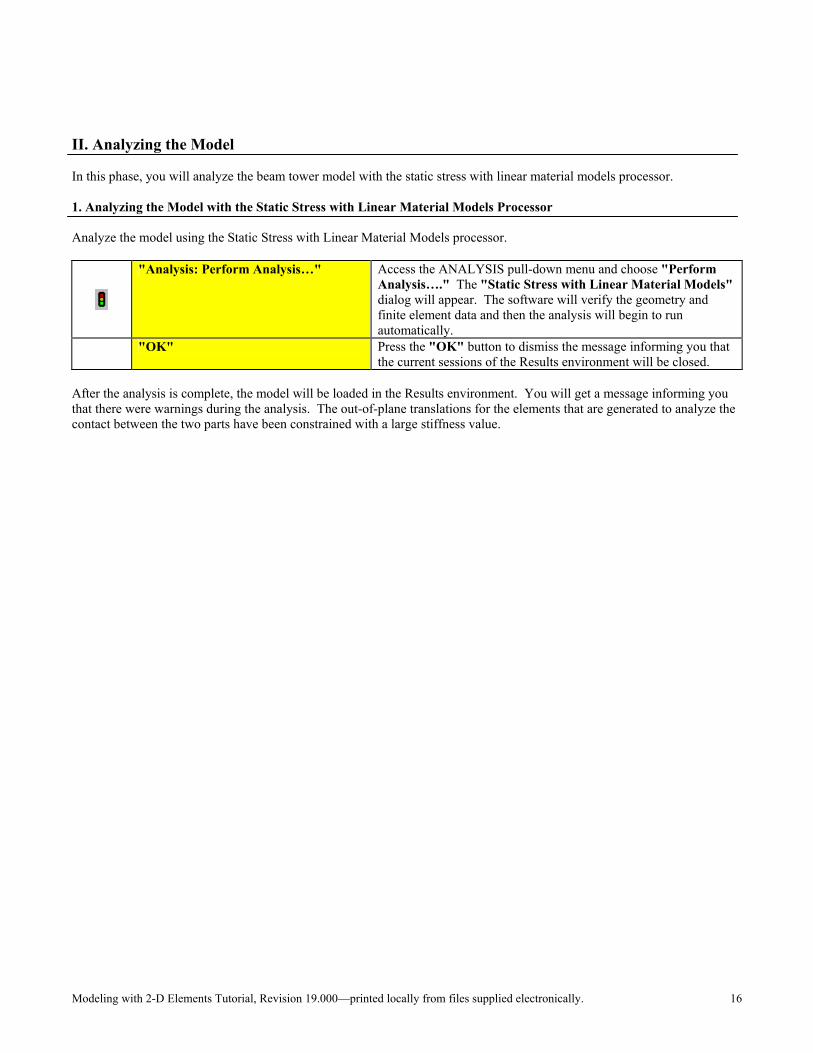
II. Analyzing the Model In this phase, you will analyze the beam tower model with the static stress with linear material models processor. 1. Analyzing the Model with the Static Stress with Linear Material Models Processor Analyze the model using the Static Stress with Linear Material Models processor.
"Analysis: Perform Analysis…" Access the ANALYSIS pull-down menu and choose "Perform Analysis…." The "Static Stress with Linear Material Models" dialog will appear. The software will verify the geometry and finite element data and then the analysis will begin to run automatically.
"OK" Press the "OK" button to dismiss the message informing you that the current sessions of the Results environment will be closed.
After the analysis is complete, the model will be loaded in the Results environment. You will get a message informing you that there were warnings during the analysis. The out-of-plane translations for the elements that are generated to analyze the contact between the two parts have been constrained with a large stiffness value.
Modeling with 2-D Elements Tutorial, Revision 19.000—printed locally from files supplied electronically. 17
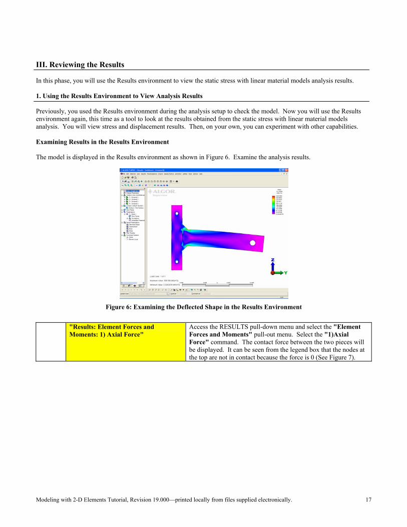
III. Reviewing the Results In this phase, you will use the Results environment to view the static stress with linear material models analysis results. 1. Using the Results Environment to View Analysis Results Previously, you used the Results environment during the analysis setup to check the model. Now you will use the Results environment again, this time as a tool to look at the results obtained from the static stress with linear material models analysis. You will view stress and displacement results. Then, on your own, you can experiment with other capabilities. Examining Results in the Results Environment The model is displayed in the Results environment as shown in Figure 6. Examine the analysis results.
Figure 6: Examining the Deflected Shape in the Results Environment
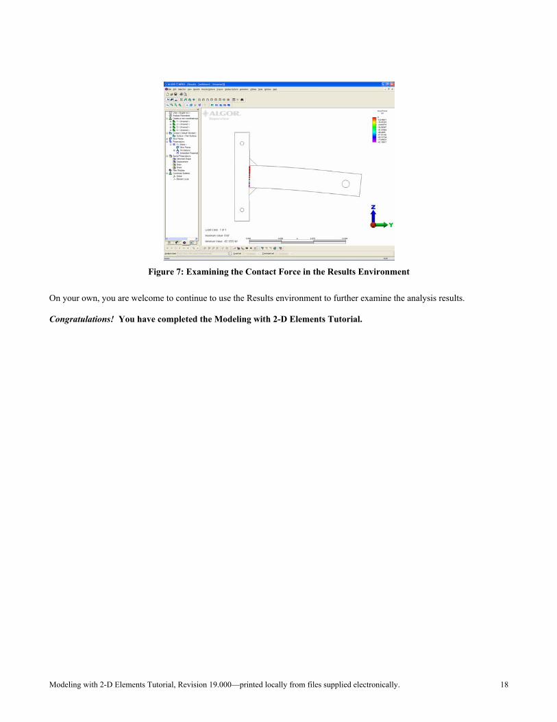
"Results: Element Forces and Moments: 1) Axial Force"
Access the RESULTS pull-down menu and select the "Element Forces and Moments" pull-out menu. Select the "1)Axial Force" command. The contact force between the two pieces will be displayed. It can be seen from the legend box that the nodes at the top are not in contact because the force is 0 (See Figure 7).
Modeling with 2-D Elements Tutorial, Revision 19.000—printed locally from files supplied electronically. 18
Figure 7: Examining the Contact Force in the Results Environment
On your own, you are welcome to continue to use the Results environment to further examine the analysis results. Congratulations! You have completed the Modeling with 2-D Elements Tutorial.