Embed Size (px)
Citation preview
7/23/2019 Modeling - UML
http://slidepdf.com/reader/full/modeling-uml 1/3
UML Modeling
1
Introduction• UML diagram is designed to let developers and customers view a software
system from a different perspective and in varying degrees of abstraction.
• UML has become a standard modeling language because it is programminglanguage independent.
• Since UML is not a methodology, it does not require any formal work product
Types of UML Diagrams
3
Types of UML Diagrams
• Use Case Diagram
Describes the functional behavior of the system as seen by the user.
• Class Diagram
Describes the static structure of the system.
• Sequence Diagram
Describe the dynamic behavior between objects of the system.
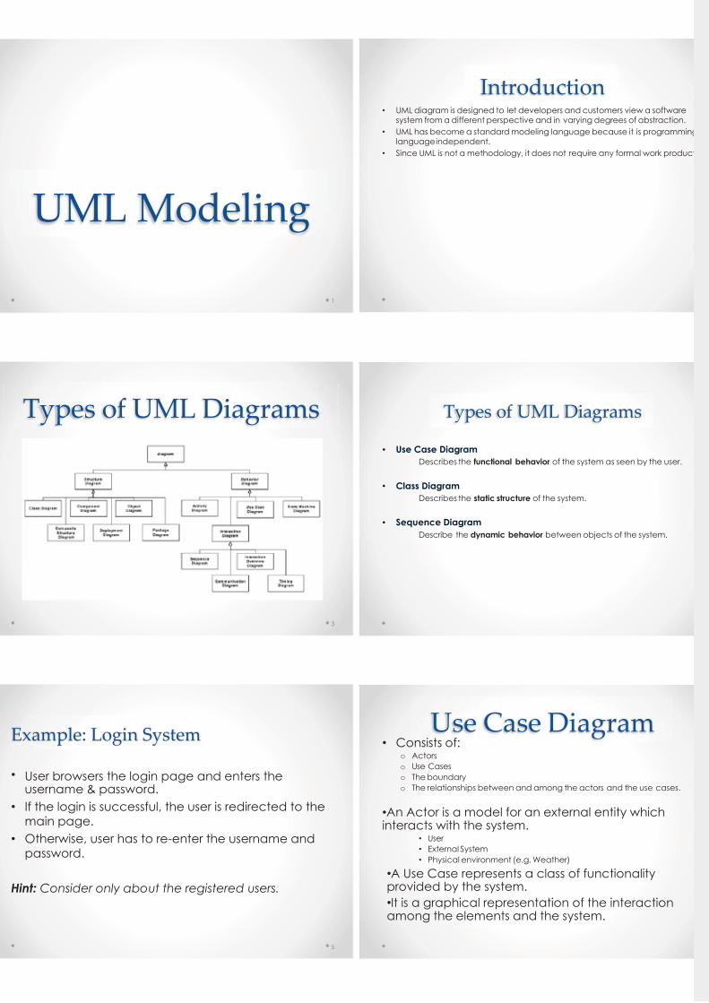
Example: Login System
• User browsers the login page and enters theusername & password.
• If the login is successful, the user is redirected to the
main page.
• Otherwise, user has to re-enter the username and
password.
Hint: Consider only about the registered users.
5
Use Case Diagram• Consists of:
o Actors
o Use Cases
o The boundary
o The relationships between and among the actors and the use cases.
•An Actor is a model for an external entity whichinteracts with the system.
• User
• External System
• Physical environment (e.g. Weather)
•A Use Case represents a class of functionalityprovided by the system.
•It is a graphical representation of the interactionamong the elements and the system.
7/23/2019 Modeling - UML
http://slidepdf.com/reader/full/modeling-uml 2/3
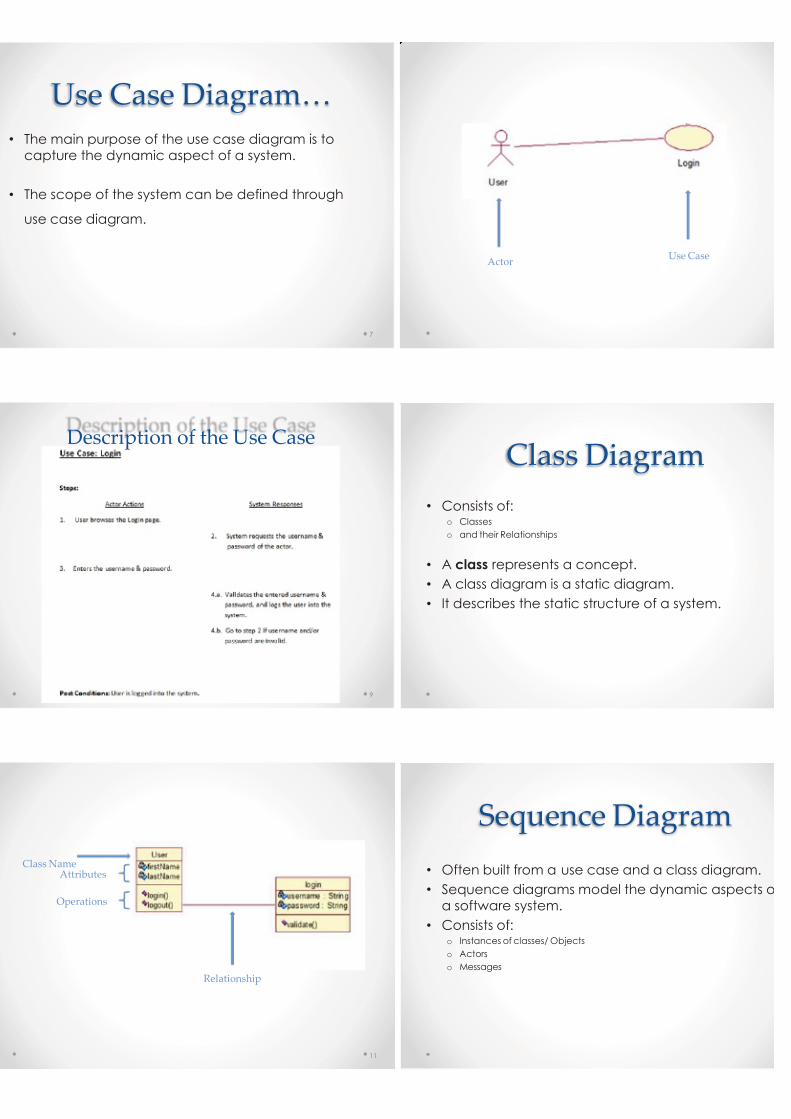
Use Case Diagram…
• The main purpose of the use case diagram is to
capture the dynamic aspect of a system.
• The scope of the system can be defined through
use case diagram.
7
ActorUse Case
Description of the Use Case
9
Class Diagram
• Consists of:o Classes
o and their Relationships
• A class represents a concept.
• A class diagram is a static diagram.
• It describes the static structure of a system.
Class NameAttributes
Operations
Relationship
11
Sequence Diagram
• Often built from a use case and a class diagram.
• Sequence diagrams model the dynamic aspects o
a software system.
• Consists of:o Instances of classes/ Objects
o Actors
o Messages
7/23/2019 Modeling - UML
http://slidepdf.com/reader/full/modeling-uml 3/3
13
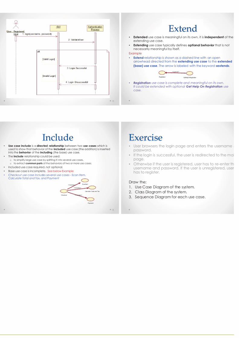
Extend• Extended use case is meaningful on its own, it is independent of the
extending use case.
• Extending use case typically defines optional behavior that is not
necessarily meaningful by itself.
Example
• Extend relationship is shown as a dashed line with an open
arrowhead directed from the extending use case to the extended
(base) use case. The arrow is labeled with the keyword «extend».
• Registration use case is complete and meaningful on its own.
It could be extended with optional Get Help On Registration use
case.
GetHelpOnRegistrationRegistration
<<extend>>
Include• Use case include is a directed relationship between two use cases which is
used to show that behavior of the included use case (the addition) is insertedinto the behavior of the including (the base) use case.
• The include relationship could be used:
o to simplify large use case by splitting it i nto several use cases,
o to extract common parts of the behaviors of two or more use cases.
• Included use case required, not optional.
• Base use case is incomplete. See below Example
• Checkout use case includes several use cases - Scan Item,Calculate Total and Tax, and Payment
15
Calculate Total and Tax
Payment
Checkout
ScanItem<<include>>
<<include>>
<<include>>
Exercise• User browsers the login page and enters the username &
password.
• If the login is successful, the user is redirected to the maipage.
• Otherwise if the user is registered, user has to re-enter thusername and password. If the user is unregistered, userhas to register.
Draw the;
1. Use Case Diagram of the system.
2. Class Diagram of the system.
3. Sequence Diagram for each use case.