Embed Size (px)
Citation preview

Elise HolmstedtDivision of Fluid and Experimental Mechanics,
Lulea University of Technology,
Lulea SE-97 187, Sweden
e-mail: [email protected]
Hans O. AkerstedtDivision of Fluid and Experimental Mechanics,
Lulea University of Technology,
Lulea SE-97 187, Sweden
T. Staffan Lundstr€omDivision of Fluid and Experimental Mechanics,
Lulea University of Technology,
Lulea SE-97 187, Sweden
Sofie M. H€ogbergSandvik Materials Technology,
Storgatan 2,
Sandviken SE-811 81, Sweden
Modeling Transport andDeposition Efficiency of Oblateand Prolate Nano- andMicro-particles in a VirtualModel of the Human AirwayA model for the motion and deposition of oblate and prolate spheroids in the nano- andmicroscale was developed. The aim was to mimic the environment of the human lung, butthe model is general and can be applied for different flows and geometries for small non-spherical particle Stokes and Reynolds numbers. A study of the motion and orientation ofa single oblate and prolate particle has been done yielding that Brownian motion disturbsthe Jeffery orbits for small particles. Prolate microparticles still display distinguishableorbits while oblate particles of the same size do not. A statistical study was done compar-ing the deposition efficiencies of oblate and prolate spheroids of different size and aspectratio observing that smaller particles have higher deposition rate for lower aspect ratiowhile larger particles have higher deposition rates for large aspect ratio.[DOI: 10.1115/1.4032934]
1 Introduction
Theories for the motion of oblate and prolate ellipsoids will beoutlined and the models presented will be applied on particle dep-osition in the respiratory airways. The theory is important for anumber of applications including particle deposition in the respi-ratory airway [1,2], the feeding of biofuels [3,4], the manufactur-ing of fiber-reinforced composites with added properties [5,6],and paper making [7,8]. Regarding particle deposition in the respi-ratory airways, the topic is significant both for evaluating healtheffects of inhaled toxic matter and for estimating the efficacy ofdrug delivery with pharmaceutical aerosols [9–11].
The development of new smart materials containing micro- andnano-particles, such as carbon nanotubes, is a very popular branchof material science nowadays. Such tiny and nonspherical par-ticles are, however, potentially toxic and thus may pose a substan-tial health risk [12]. Carbon nanotubes are approximately10–100 nm in diameter with lengths of around 150 lm and can betreated as prolate ellipsoids. Although usually smaller than asbes-tos fibers, there are concerns that they may cause similar adversehealth effects upon inhalation. Nanoparticles may be given addi-tional shapes like oblate spheroids [13]. This is a shape that alsomay describe wood chips and microparticles for drug delivery[14]. Hence, there are many reasons to do fundamental studies ofthe motion of prolate and oblate ellipsoids [15].
There are two main techniques for the analysis of the transportof particles and their deposition for a given flow and geometry.One method is to solve the particle equations of motion for a flowfield given by the solution of the Navier–Stokes equations. Toinclude effects of Brownian motion, a stochastic force is intro-duced. If launching a large number N of particles, particle deposi-tion statistics can be disclosed. The error of the method whenconsidering stochastic differential equations of this kind is oforder O N�1=2ð Þ [16]. This method has been successfully appliedto derive the deposition of prolate micro- and nano-particles for afully developed pipe flow [17]. The second approach is to utilize
the Fokker–Planck equation to find solutions for the probabilitydensity function [16]. Statistical averages can then be found frommoments of the probability density function. For spherical par-ticles, this is equivalent to solving a steady convective–diffusionequation for the probability density function as a function ofspace. To find the deposition of particles, the diffusive flux is inte-grated over the boundary of the pipe. This method has, forinstance, been used to study the deposition of spherical particlesin a model airway with cartilaginous rings, representing the largeconducting airways [18]. For nonspherical particles, the probabil-ity density function also depends on the orientation described bythe Euler angles, and the deposition is found by averaging overthe angles and integrating the probability diffusive flux over thepipe boundary [19]. Comparing the results between the two ratherdifferent approaches given in Refs. [17] and [19], a good agree-ment is found. The Fokker–Planck equation for nonspherical par-ticles was considered for fully developed pipe flow by Asgharianand Gradon [20]. It should be pointed out that this method is aone-way coupling method between the continuous phase and thediscrete phase. This means that the presence of the particles doesnot influence the flow of the continuous phase.
The present study is a continuation of the previous work [17] inwhich particle tracking of prolate spheroids in different genera-tions of the human lung was considered. Here, using the samemethod, we consider the particle tracking of the other type ofspheroids called oblate spheroids. We consider a single particlestudy comparing the Jeffery types of orbits for oblate and prolateparticles, with and without the effects of Brownian motion. Wealso consider a comparison of the deposition statistics for the twotypes of particles for the application of the deposition in the differ-ent generations of the human lung.
2 Simulation Setup
We assume a flow speed corresponding to light physical activ-ity for which the tracheal flow rate is 431 cm3=s. The Reynoldsnumber for the flow in trachea is then about 2000, and therefore inthe transition region between laminar and turbulent flow. In gener-ation 2, the Reynolds number is about 1100 and therefore laminar.In this study, we will consider laminar flow which means that this
Contributed by the Fluids Engineering Division of ASME for publication in theJOURNAL OF FLUIDS ENGINEERING. Manuscript received April 28, 2015; finalmanuscript received February 3, 2016; published online May 2, 2016. Assoc. Editor:Daniel Maynes.
Journal of Fluids Engineering AUGUST 2016, Vol. 138 / 081203-1Copyright VC 2016 by ASME
Downloaded From: http://fluidsengineering.asmedigitalcollection.asme.org/ on 10/05/2016 Terms of Use: http://www.asme.org/about-asme/terms-of-use

study is limited to conditions from generation 2 and below. Themaximum velocity for the flow to be laminar in generation 2 isabout 3.5 m/s. We assume that the flow is in the y-direction withan inlet in the y¼ 0 plane. A representation of the geometry canbe seen in Fig. 1. In this figure, the initial positions of an oblateand prolate particle in a single particle simulation are also defined.Two types of geometries will be considered: a pipe with uniformcross section to study the evaluation of orientation of single par-ticles and a larger-scale model where the deposition rates are cal-culated for a number of these pipes with a radius and length thatgoes from large to small corresponding to the size of the variousbronchi. This information is then compiled to represent a modelof the lung.
2.1 Particle Geometry. The particles studied are oblate andprolate spheroids with two defining characteristics: b, aspect ratio,and df, geometric diameter. b is defined as radius of the major axisof the spheroids divided by the minor, so bprolate ¼ a=b andboblate ¼ b=a, where a is the polar semi-axis and b is the equato-rial. The geometric diameter is based on the equatorial radius, sodf ¼ 2b. This is illustrated in Fig. 2.
2.2 Particle Equations of Motion. Two coordinate systemsare defined to describe the movement of the particles. Globalcoordinates x; y; z½ � and local ones x0; y0; z0½ � fixed to the particlewith the polar axis along z0. The global coordinate system has theinlet of the airway on the x; z½ � plane with origin fixed in the centerof the circular inlet and the flow field moving in the positive y-direction. As particles rotate, the angle between the local andglobal coordinates is described using Euler angles, as depicted inFig. 3.
For this study, we assume that the Stokes number is small forthe particles such that inertia may be neglected. To justify thisapproach, we start from the full set of equations of motion for theparticles
md2xi
dt2¼ Fh
i þ Fgi þ f Br
i (1)
Ii �dxi
dtþ eijkxjxkIk ¼ Th
i þ TBri (2)
Here, Ii is the moment of inertia chosen with respect to the princi-pal axes of the body and xi is the components of the angularvelocity.
The forces affecting the particles are the hydrodynamic, gravi-tational, and Brownian, and the torques are hydrodynamic andBrownian. Before we consider the Stokes numbers and a discussion
about the validity of neglecting inertia, we describe the different rel-evant forces in Secs. 2.3–2.5.
2.3 Hydrodynamic Force and Torque. The drag force onthe particles considered in this study may be expressed as
Fh ¼ 3plAT
d? 0 0
0 d? 0
0 0 dk
2664
3775A
u� dx
dt
v� dy
dt
w� dz
dt
266666664
377777775
(3)
and is thus dependent on the orientation of the particle in theStokes flow regime. In this equation, l is the dynamic viscosity ofthe fluid, u; v;w½ � are the components of the fluid velocity,
dx=dtð Þ; dy=dtð Þ; dz=dtð Þ½ � are the components of the particlevelocities, and A is the rotation matrix between the local andglobal coordinates and defined as
A ¼cwc/� chs/sw cws/þ chc/sw shs/�swc/� chs/cw �sws/þ chc/cw shc/
shsw �shcw ch
24
35 (4)
where c/ ¼ cos /; s/ ¼ sin /, etc., and /; h;wð Þ are the Eulerangles of the particles.
2.3.1 Translation. For a prolate spheroid, d? and dk are theStokes diameters oriented perpendicular and parallel to the direc-tion of motion, respectively, and are given by [17]
Fig. 1 A representative sketch of the geometry used in thesimulations with the initial position for an oblate and a prolateparticle in the single particle runs
Fig. 2 Illustration of the spheroids used in the simulations: (a)oblate particle with polar semi-axis a and equatorial b and (b)prolate particle with polar semi-axis a and equatorial b
Fig. 3 Euler angles connecting a particles local coordinates tothe global ones [5]
081203-2 / Vol. 138, AUGUST 2016 Transactions of the ASME
Downloaded From: http://fluidsengineering.asmedigitalcollection.asme.org/ on 10/05/2016 Terms of Use: http://www.asme.org/about-asme/terms-of-use

d?df¼
8
3b2 � 1� �
Ct?
2b2 � 3ffiffiffiffiffiffiffiffiffiffiffiffiffib2 � 1
p ln bþffiffiffiffiffiffiffiffiffiffiffiffiffib2 � 1
q� �þ b
" # (5)
dkdf¼
4
3b2 � 1� �
Ctk
2b2 � 1ffiffiffiffiffiffiffiffiffiffiffiffiffib2 � 1
p ln bþffiffiffiffiffiffiffiffiffiffiffiffiffib2 � 1
q� �� b
" # (6)
Here, b is the fiber aspect ratio, df is the geometric diameter, andCtk and Ct
? are the slip correction factors for the fluid dynamicdrag that are included to extend the validity of the drag force toinclude particles that are so small that their diameter is close tothe mean free path of air molecules.
Equations (5) and (6) are valid for prolate as well as oblatespheroids if oblate spheroids are defined with b < 1. This meansthat the imaginary part of the logarithm and square root must betaken into account; hence, b is replaced with 1=b in Eqs. (7) and(8) so that the aspect ratio is defined as greater than unity for bothprolate and oblate spheroids. The Stokes parameters for oblatespheroids are then given by
d?df¼
8
3b2 � 1� �
Ct?
b 3b2 � 2� �ffiffiffiffiffiffiffiffiffiffiffiffiffib2 � 1
p arctan
ffiffiffiffiffiffiffiffiffiffiffiffiffib2 � 1
q� �� b
" # (7)
dkdf¼
4
3b2 � 1� �
Ctk
b b2 � 2� �ffiffiffiffiffiffiffiffiffiffiffiffiffib2 � 1
p arctan
ffiffiffiffiffiffiffiffiffiffiffiffiffib2 � 1
q� �þ b
" # (8)
This result is also given by Happel and Brennen [21].No exact expression for the slip correction factors exists for
prolate and oblate spheroids, and an approximate method by Dah-neke [22] is applied. This method will be outlined in Sec. 2.3.3.
2.3.2 Rotation. The equations for the fluid dynamic torque foran ellipsoid body in a viscous shear flow as derived by Jeffery[23] and simplified for the current case can be written in the fol-lowing manner:
Thx0 ¼
1
Br?
n0 � xx0ð Þ � b2 � 1
b2 þ 1
!_ey0z0
" #(9)
Thy0 ¼
1
Br?
g0 � xy0� �
� b2 � 1
b2 þ 1
!_ex0z0
" #(10)
Due to rotational symmetry rotation about the major axis does notaffect the transport and is therefore omitted. The tensor xi0 is thefiber angular velocity, _eij ¼ 1=2ð Þ @uj=@xi
� �þ @ui=@xj
� �� �is the
elements of the deformation rate, and n; g; f½ �T ¼ 1=2ð Þ r � uð Þ isthe spin tensor. The latter two tensors are derived from the globalflow field and are translated to local equivalents by
_ei0j0 ¼ A_eijAT (11)
n0; g0; f0� �T ¼ A n; g; f½ �T (12)
The angular mobility for prolate spheroids may be expressedas [17]
Br?;prolate ¼
3Cr?
2b2 � 1ffiffiffiffiffiffiffiffiffiffiffiffiffib2 � 1
p ln bþffiffiffiffiffiffiffiffiffiffiffiffiffib2 � 1
q� �� b
" #
2pld3f b4 � 1� � (13)
For oblate spheroids, this mobility is given by the followingrelationship
Br?;oblate ¼
3Cr?
2� b2� �
bffiffiffiffiffiffiffiffiffiffiffiffiffib2 � 1
p arctan
ffiffiffiffiffiffiffiffiffiffiffiffiffib2 � 1
q� �� b
" #
2pld3f
1
b2� b2
� � (14)
2.3.3 Slip Corrections Factors. No exact expressions for thedrag of prolate and oblate spheroids exist in the free molecularflow limit where Kn ¼ 2k=df
� �approaches infinity, in which k is
the mean free path of the air molecules. For cylinders, however,expressions have been derived by Dahneke [24]. Therefore, in thislimit, the drag of prolate and oblate spheroids is modeled by theresults of a cylinder. To extend the validity for the drag forcefrom small Knudsen numbers Kn to large Kn, the Cunninghamfactors are applied with an adjusted radii as suggested by Dahneke[24]. The Cunningham factors for prolate spheroids are given byH€ogberg et al. [17]. Using the replacement b! 1=b gives the fol-lowing result for oblate spheroids:
Ci0 ¼ 1þ df
2ri0Kn 1:257þ 0:4 exp
�2:2ri0
df Kn
� � (15)
The adjusted radii for translational motion parallel and perpen-dicular to the flow are then expressed as
r1 ¼1:657df b
16 b2 � 1� � (16)
K1 ¼1ffiffiffiffiffiffiffiffiffiffiffiffiffi
b2 � 1p (17)
K3 ¼ K1 log bþ 1
K1
� �(18)
K2 ¼ b� K3 (19)
rt? ¼
r1
2
3b2 þ 4ffiffiffiffiffiffiffiffiffiffiffiffiffib2 � 1
p arctan
ffiffiffiffiffiffiffiffiffiffiffiffiffib2 � 1
q� 1
" #
� K21K2
6� pð Þ4
f � 2
� �þ K3 4� 4� p
2f
� �þ f
b
" #
(20)
rtk ¼ r1
2b2 � 1ffiffiffiffiffiffiffiffiffiffiffiffiffib2 � 1
p arctan
ffiffiffiffiffiffiffiffiffiffiffiffiffib2 � 1
qþ 1
" #
� K21K2 4� 6� pð Þ
2f
� �b�2 þ K3f þ f
b
" # (21)
An adjusted radii for rotational movement of oblate spheroidsaround its axis is given by
Journal of Fluids Engineering AUGUST 2016, Vol. 138 / 081203-3
Downloaded From: http://fluidsengineering.asmedigitalcollection.asme.org/ on 10/05/2016 Terms of Use: http://www.asme.org/about-asme/terms-of-use

rr? ¼
1:675df
b3
2
2� b2� �
� bffiffiffiffiffiffiffiffiffiffiffiffiffib2 � 1
p arctan
ffiffiffiffiffiffiffiffiffiffiffiffiffib2 � 1
q� �� b
1
b2� b2
266664
377775
� 1
4þ 2b
4þ 2bð Þ2
4þ 2bð Þ3
8
þ fp� 6
48� 2b
8� 2bð Þ2
8þ p� 4ð Þ 2bð Þ3
64
� �#(22)
2.4 Gravitational Settling. One deposition mechanism isgravitational settling or sedimentation. It comes into play for largeparticle masses for longer time periods and is most noticeablewithin horizontal small airways. Particle density is usually muchgreater than the surrounding air, and thus buoyancy can beneglected. The gravitational force is defined in the positive z-direction with magnitude
Fgz ¼ pqf gd3
f b=6 (23)
for prolate spheroids and
Fgz ¼ pqf gd3
f =6b (24)
for oblate spheroids, where qf is the density of the particle and g isthe gravitational acceleration.
2.5 Brownian Motion. The Brownian force and torque aremodeled as independent zero-mean Gaussian white noise proc-esses [17], which for spheroids take the following form:
FBri0 tð Þ ¼ vt
i0
ffiffiffiffiffiffiffiffipSt
i0dt
r(25)
TBri0 tð Þ ¼ vr
i0
ffiffiffiffiffiffiffiffipSr
i0dt
r(26)
where vti0 and vr
i0 are standard normally distributed random num-bers and dt is a Brownian time increment chosen as dt ¼ 10 ls af-ter a numerical study where the results were compared to atheoretical value for diffusion velocity [25]. The spectral inten-sities St
i0 and Sri0 are given by
Sti0 ¼
2rT
p1
Bti0
(27)
Sri0 ¼
2rT
p1
Bri0
(28)
in which r is the Boltzmann constant and T is the absolute temper-ature. Br
i0 is given in Eqs. (13) and (14) and
Bti0 ¼ 1=3pldi0 (29)
The diffusion coefficients are given by
Dti0 ¼ rTBt
i0 (30)
Dri0 ¼ rTBr
i0 (31)
2.6 Stokes Numbers. To define the Stokes number, it is suffi-cient to consider the hydrodynamic forces and torques. Addingthe inertia in Eq. (3), the equation of motion for the translationalpart is given by
m
d2x
dt2
d2y
dt2
d2z
dt2
2666666664
3777777775¼ 3plAT
d? 0 0
0 d? 0
0 0 dk
2664
3775A
u� dx
dt
v� dy
dt
w� dz
dt
266666664
377777775
(32)
An order of magnitude estimate of the terms in this equation givesfor the perpendicular and the parallel part
qp
4
24pd3
f bU2
D� 3pldf
d?df
U (33)
qp
4
24pd3
f bU2
D� 3pldf
dkdf
U (34)
where U is a typical velocity of the flow and D is the typicallength scale of the flow.
Defining the Stokes number as the ratio between the inertialforce and the hydrodynamic force, we have for prolate spheroids
Stt? ¼qpd2
f b
18lU
D
df
d?(35)
Sttk ¼qpd2
f b
18lU
D
df
dk(36)
with the Stokes parameters given by Eqs. (5) and (6). For oblatespheroids, similar expressions for the Stokes numbers are givenby letting b! 1=b and use the Stokes parameters (7) and (8).
The corresponding order of magnitude estimate for the rota-tional equation of motion gives the Stokes number as
Str ¼ IxxBr?U
D(37)
where Br? is the angular mobility given by Eq. (13) for prolate
spheroids and by Eq. (14) for oblate spheroids, and the relevantmoment of inertia is given for prolate spheroids by
Ixx ¼ Iyy ¼1
120qppb 1þ b2
� �d5
f (38)
and for oblate spheroids as
Ixx ¼ Iyy ¼1
120qppb�1 1þ b�2
� �d5
f (39)
For the neglect of the inertia terms, the Stokes number must bemuch smaller than one. In the cases that follow, this is more orless satisfied. A discussion of the Stokes number is thus providedin each particular case being studied.
2.7 Numerical Setup for Single Particle Study. To be ableto properly observe the Jeffrey orbits made by a single particle, itis necessary to follow the particle for a longer distance than forthe airway model used in the multiparticle deposition simulations.In simulations of non-Brownian motion, that is, particles onlyaffected by fluid shear, the nondimensional diameter of the airwayhas no large effect on the resulting Jeffery orbits since the flowshear rate U/R is similar between generations. When studyingBrownian motion, a larger airway is preferable since it slowsdown the process and makes it easier to do observations, so forthe following examples, generation 4 was chosen.
When keeping b constant, the geometric diameter of the par-ticles has no impact on the Jeffery orbits of particles not affected
081203-4 / Vol. 138, AUGUST 2016 Transactions of the ASME
Downloaded From: http://fluidsengineering.asmedigitalcollection.asme.org/ on 10/05/2016 Terms of Use: http://www.asme.org/about-asme/terms-of-use
by Brownian motion, but has an inverse relationship with Brown-ian motion as it is, by its nature, a force that affects small par-ticles. Therefore, a relatively large particle with df¼ 1 lm waschosen, so the impact of Brownian motion can be observed on therotational movement but it is not the dominating force acting onthe particles and its translational contribution is minimal. AllStokes numbers for this case are very small so the inertia can beneglected.
The placement of both oblate and prolate particles at the begin-ning of the simulations is such that the large surface of the particleis facing the flow as shown in Fig. 1. For prolate particles, thisimplies that the particle is directed perpendicular to the flowwith h ¼ 90 deg since its z0-axis is directed along the length of theparticle. Oblate particles are placed parallel to the flow withh ¼ 0 deg since its z0-axis is perpendicular to the surface of theparticle. The angle / describes the tilt of the particles z0-axis fromthe global z-axis (see Fig. 3). The particles initial position is suchthat / ¼ 0 deg, and thus, the pressure gradient over the particleson the horizontal plane is zero. The larger the distance betweenthe center of the airway and the particles initial position, theslower the particle will move and thus experiences more Jefferyorbits. In this simulation, the initial position was at a distance of0:7r from the center, where r is the radius of the airway.
2.8 Numerical Setup for Simulation of DepositionEfficiency in Human Airways. Lungs can be seen as pipesdivided into smaller pipes that in turn are divided into evensmaller pipes, etc. Each of these divisions is called a generation.The simulations are set up here to start at the second generation,where for light physical activity the flow is laminar. Using Wei-bel’s model [26], it is furthermore assumed that pipes in this gen-eration are 19 mm long and have a diameter of 4.15 mm. Thesimulations are performed down to the 16th generation where theradius of the pipes is assumed to be 0.2 mm and the length1.65 mm [26]. The tracheal flow rate was 431 cm3=s correspond-ing to a tidal volume of 750 ml with an air temperature of 310 Kand the particles have unit density. The model is currently setupand focused on the straight bronchi, not the intersections. Distur-bances in the flow at the intersections are mainly driven by inertiaand are therefore more important for higher Re than considered inthis study. Secondary flow that can be induced in the interceptionsand a partly developing flow at one side of the pipe after the inter-section are therefore neglected in the current setup.
The purpose of the present work is to extend the methodologydeveloped in Ref. [17] for prolates to oblates and to compare thebehavior of these two shapes on the deposition rate in the humanlung.
Simulations are thus run with 10,000 particles with a density of1000 kg=m3 for each combination of aspect ratio and geometricdiameter, and the deposition rate is calculated by observing howmany particles are deposed at the walls of the lungs as a ratio ofthe number of particles in the set. A study of the number of par-ticles used in the simulation shows that 10,000 particles areenough to gather statistically accurate results. Larger number ofparticles produces the same results. This is also done in accord-ance to previously published work on the topic [17].
3 Results and Discussion
To elucidate the motion of oblate and prolate spheroids inhuman airways, it is necessary to both scrutinize the detailedmotion of a single particle and the accumulated results of a largenumber of particles.
3.1 Following One Particle. Oblate and prolate spheroids arefirst studied for the case when they are only influenced by the flowfield within the airways, discarding both Brownian motion andgravitational settling.
Oblate and prolate spheroids exhibit a similar behavior withJeffery orbits appearing at the same interval, which can be seen in
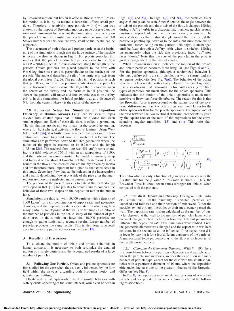
Figs. 4(a) and 5(a). In Figs. 4(b) and 5(b), the particles Eulerangles h and / can be seen. Since h denotes the angle between thez0-axis of the particle and the z-axis of the flow, it changes 180 degduring a Jeffrey orbit in a characteristic manner, quickly aroundpositions perpendicular to the flow and slowly otherwise. Theangle / describes the rotational angle around the flow, i.e., if theparticle is pointing up, down or to the sides, but since there are nohorizontal forces acting on the particle, this angle is unchangeduntil halfway through a Jeffery orbit when it switches 180 deginstantaneously when the side that previously faced “up” nowfaces “down.” Note that the size of the particles in the plots isgreatly exaggerated for the sake of clarity.
When Brownian motion is included, the motion of the prolateand oblate particles becomes more irregular (see Figs. 6 and 7).For the prolate spheroids, although a randomized behavior isobvious, Jeffery orbits are still visible, but with a shorter and notas regular periodicity (see Fig. 7(a)). The behavior of the oblatespheroids is less regular without any Jeffery orbits (see Fig. 6(a)).It is also obvious that Brownian motion influences / for bothtypes of particles but much more for the oblate spheroids. Thisindicates that the motion of the oblate spheroids is much moresensitive to Brownian force disturbance. The reason for this is thatthe Brownian force is proportional to the square root of the rota-tional diffusion coefficient which is in general much larger for theoblate spheroids than for the prolate spheroids. The square root ofthe ratio between the two rotational diffusion coefficients is givenby the square root of the ratio of the expressions for the corre-sponding angular mobilities (13) and (14). This ratio thenbecomes
q ¼ffiffiffiffiffiffiffiffiffiffiffiffiffiffiffiffiffiBr?; oblate
Br?; prolate
s
¼
ffiffiffiffiffiffiffiffiffiffiffiffiffiffiffiffiffiffiffiffiffiffiffiffiffiffiffiffiffiffiffiffiffiffiffiffiffiffiffiffiffiffiffiffiffiffiffiffiffiffiffiffiffiffiffiffiffiffiffiffiffiffiffiffiffiffiffiffiffiffiffiffiffiffiffiffiffiffiffiffiffiffiffiffiffiffiffiffiffiffiffiffiffiffiffiffi2b2 � 1ffiffiffiffiffiffiffiffiffiffiffiffiffi
b2 � 1p ln bþ
ffiffiffiffiffiffiffiffiffiffiffiffiffib2 � 1
q� �� b
!b4 � 1� �
2� b2� �
bffiffiffiffiffiffiffiffiffiffiffiffiffib2 � 1
p arctan
ffiffiffiffiffiffiffiffiffiffiffiffiffib2 � 1
q� �� b
!1
b2� b2
� �
vuuuuuuut (40)
This ratio which is only a function of b increases quickly with theb value, and for the b value 5, this ratio is about 7. Thus, theBrownian force is about seven times stronger for oblates whencompared with the prolates.
3.2 Statistical Deposition Efficiency. During multiple parti-cle simulations, 10,000 randomly distributed particles arelaunched and followed and their position of exit saved. Either theparticles exited through the outlet or their mass center passed thewall. The deposition rate is then calculated as the number of par-ticles deposed at the wall to the number of particles launched atthe inlet. To get a clear picture on how the different parametersinfluence the deposition rate, two main cases were studied. First,the geometric diameter was changed and the aspect ratio was keptconstant. In the second case, the influence of the aspect ratio b isin focus by varying it for a few different diameters of the particles.A gravitational force perpendicular to the flow is included in allthe results presented here.
3.2.1 Changing the Geometric Diameter. With b¼ 100, thereis a correlation between deposition efficiencies and particle size;when the particle size increases, so does the deposition rate inde-pendent of particle type, except for the case with the smallest par-ticles with a geometric diameter of 10 nm, where the depositionefficiencies increase due to the greater influence of the Browniandiffusion (see Fig. 8).
In Fig. 8, the deposition rates are shown for a pair of one oblateparticle and one prolate of the same volume such that the follow-ing relation holds:
Journal of Fluids Engineering AUGUST 2016, Vol. 138 / 081203-5
Downloaded From: http://fluidsengineering.asmedigitalcollection.asme.org/ on 10/05/2016 Terms of Use: http://www.asme.org/about-asme/terms-of-use

df ;oblate ¼ b2=3df ;prolate (41)
The largest oblate particle and the largest prolate particle shouldthen be compared. It is seen that for the largest pair of particles,the oblates have a slightly higher deposition rate. This can beexplained by the differences in the diffusion coefficients for thetwo particle types. As shown in Ref. [19], the effective diffusioncoefficient after integration about the Euler angles becomes
Dt ¼ 2
3Dt? þ
1
3Dtk (42)
Expanding the diffusion coefficients for large b, we then get forthe oblate and prolate particles
Dtoblate �
jT pb� 1ð Þ6pldf ;ob
(43)
Dtprolate �
jTln 2bð Þ3pldf ;pb
(44)
The ratio between the diffusion coefficients using the relation (41)then follows
Fig. 4 Description of the motion of an oblate spheroid with df 5 1 lm, b 5 5 and in an airway of generation 4: (a) the rotation ofone oblate particle plotted at regular intervals as it moves through an airway and (b) the angles, q and f, describing the rotationof the oblate particle
Fig. 5 Description of the motion of a prolate spheroid with df 5 1 lm, b 5 5 and in an airway of generation 4: (a) the rotation ofone prolate particle plotted at regular intervals as it moves through an airway and (b) the angles, q and f, describing the rota-tion of the prolate particle
Fig. 6 Similar setup as in Fig. 4 but with Brownian motion included: (a) snapshots of an oblate particle as it moves throughthe airway and (b) the angular positions of an oblate particle
081203-6 / Vol. 138, AUGUST 2016 Transactions of the ASME
Downloaded From: http://fluidsengineering.asmedigitalcollection.asme.org/ on 10/05/2016 Terms of Use: http://www.asme.org/about-asme/terms-of-use

Dt?;oblate
Dt?;prolate
� pb� 2
2b2=3ln 2bð Þ(45)
which is about 1.4 for b¼ 100, meaning that comparing oblatesand prolates of the same volume, the deposition of oblates isslightly higher than the prolates in agreement with the results inFig. 8.
The discussion above holds in the limit of small Knudsen num-ber and for particles smaller than about 70 nm, so that if the Knud-sen number is large, the diffusion coefficients must be modifiedby the Cunningham factors.
The Stokes number has been calculated for all the examples inFig. 8 both the translational and rotational Stokes numbers. Someparticle diameters are quite big, an oblate of diameter 107 lm anda prolate of diameter 5 lm. For these particles, the largest transla-tional Stokes number is found: for the oblate 0.32 in generation 6and for the prolate 0.25 in generation 4. The rotational Stokesnumber is for the largest oblate particle about 0.1 observed in gen-eration 6, and for the largest rotational Stokes number for the larg-est prolates is also about 0.1. So, for the translational part, theStokes number for the largest particles is smaller than unity butnot by very much, and these larger particles can therefore be con-sidered to be at the upper limit for which the theory is valid.
Another way to analyze the results is to look at the depositionrates as a number of particles travels through generations 2–16and derive the probability that a particle ends up in a specific gen-eration dependent on it traveling through the generations above it.If pn is the deposition rate for generation n in accordance to theresults presented in Fig. 8, we now focus on the deposition qn ineach generation where
q2 ¼ p2 (46)
qn ¼ 1� qn�1ð Þpn n > 2 (47)
In this model, it is easy to distinguish in which generation mostfibers are being deposed, as displayed in Figs. 9(a) and 9(b) wherethe deposition efficiencies for oblate and prolate spheroids havebeen plotted, respectively. Larger oblate spheroids are beingdeposed higher up in the airway while smaller particles have aquite even distribution. For prolate particles, it is clear that themajority of the particles are being deposed in the smallestbronchi.
3.2.2 Changing the Aspect Ratio. To make it easier to com-pare the results for oblate particles with those for prolate particles,the results from the simulations of the prolate particles depositionrate are plotted against the inverse of their b value on the x-axison a logarithmic scale. Each line represents the deposition in eachgeneration of bronchi with the prolate particles on the left-handside, the oblate particles on the right-hand side, and a sphericalparticle with an aspect ratio of b¼ 1 in the middle. To comparethe particles of similar size, particles with the same minor axis arechosen; to achieve this, the geometric diameter df ; oblate for theoblate particles is defined as df ; oblate ¼ bdf ; prolate.
To see the effect of the aspect ratio on the deposition efficien-cies of particles, a number of simulations were carried out with afixed diameter of the minor axis and an aspect ratio that goes froma prolate particle with bp ¼ 100 down to b¼ 1, and then up tobo ¼ 100 for oblate particles (see Fig. 10).
As shown in Figs. 10(a) and 10(b), for smaller particles, themaximum deposition rates occur for spherical particles while par-ticles with a higher aspect ratio have a lower deposition rate. Forsmaller particles, the Brownian force has the largest influence onthe movements of particles; therefore, it is natural that a smallerparticle, such as the sphere, has a larger deposition rate.
Once the particles get larger, this behavior can be observed tochange. Studying Fig. 10(c), the deposition efficiencies for par-ticles with a minor axis diameter of df¼ 460 nm start increasingfor oblate spheroids with a large b compared to prolate spheroids.Oblate spheroids with a small b can still be seen to be followingthe earlier pattern which gives a minimum deposition rate foroblate spheroids somewhere around b¼ 3. At particle size of
Fig. 7 Similar setup as in Fig. 5 but with Brownian motion included: (a) snapshots of a prolate particle as it moves throughthe airway and (b) the angular positions of a prolate particle
Fig. 8 Simulations of particles with a fixed aspect ratio ofb 5 100, but with a varied geometric diameter so that the oblateand prolate particle volumes are comparable
Journal of Fluids Engineering AUGUST 2016, Vol. 138 / 081203-7
Downloaded From: http://fluidsengineering.asmedigitalcollection.asme.org/ on 10/05/2016 Terms of Use: http://www.asme.org/about-asme/terms-of-use
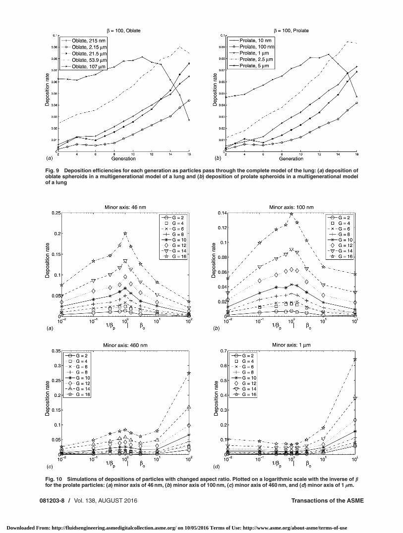
Fig. 9 Deposition efficiencies for each generation as particles pass through the complete model of the lung: (a) deposition ofoblate spheroids in a multigenerational model of a lung and (b) deposition of prolate spheroids in a multigenerational modelof a lung
Fig. 10 Simulations of depositions of particles with changed aspect ratio. Plotted on a logarithmic scale with the inverse of bfor the prolate particles: (a) minor axis of 46 nm, (b) minor axis of 100 nm, (c) minor axis of 460 nm, and (d) minor axis of 1 lm.
081203-8 / Vol. 138, AUGUST 2016 Transactions of the ASME
Downloaded From: http://fluidsengineering.asmedigitalcollection.asme.org/ on 10/05/2016 Terms of Use: http://www.asme.org/about-asme/terms-of-use

df¼ 1 lm, the behavior of the oblate spheroids is constant withincreasing deposition rates as b increases, as shown in Fig. 10(d).A similar pattern for prolate particles is also starting to appear.This behavior arises from the increasing influence gravity has onthe heavier particles. The relative magnitude of the gravitationaleffect for the different particles can be gathered by comparing theparticle volumes
Vo
Vp¼
1
bd3
f o
bd3f p
(48)
where df o ¼ bdf p. So
Vo
Vp¼ b (49)
Since the particles are quite small in the particular cases men-tioned above, all Stokes numbers are quite small for all b so theinertia can safely be neglected.
4 Conclusions
A semi-analytical model describing the motion of oblate andprolate spheroids on the nano- and micro-scales has been devel-oped, and simulations enabling both single particle tracking andaggregation of multiple particle deposition were carried out. Inthis work, the focus was on particle movement and deposition inbronchi, but the model can be applied to a variety of cases withsmall particle Reynolds and Stokes numbers including moreadvanced models of the geometry of the human lung [27].
It is clear from the simulations that the shape of the particlesgreatly influences the deposition of said particles. It is well knownthat reduced particle size reduces the gravitational sedimentationbut increases the Brownian diffusion, which corresponds to theresults from this model. What the model has shown is how greateach of those effects has on the particles and also how differentshapes are affected differently. There is a clear connectionbetween a reduction in deposition rate and a reduced particlediameter meaning a reduction of the effect of gravitational sedi-mentation. There is also an increase in deposition for the verysmall particles, where the Brownian diffusion starts to have a no-ticeable effect which leads to a deposition minimum for a certaingeometric diameter for each aspect ratio. There is also a higherdeposition rate for the larger oblate spheroids as compared to pro-late spheroids. This behavior can be traced back to the greaterinfluence the Brownian forces have on them. There was also a no-ticeable influence on the results from changing the aspect ratios ofthe particles. The deposition efficiencies for the smallest particleswere the lowest for both the oblate and prolate spheroids with thehighest aspect ratio, with spherical particles having the highestdeposition rates. For particles in the microscale, this behavior wasinverse and the highest deposition was found with the highestaspect ratios. By running simulations without gravitational forcesacting on the particles, this behavior is concluded to be influencedby sedimentation effects. Thus, smaller prolate spheroids will getthe deepest into the lungs while oblate spheroids will be inter-cepted in the larger bronchi.
The stability of the path of the particle is shown to be greatlydependent on particle shape and size. Particles that are only influ-enced by the flow field will display clear Jeffery orbits, whose fre-quency is only set by the particle aspect ratio and where in theflow field the particle is moving. When the particles are under theinfluence of Brownian forces, this behavior is changed and parti-cle type and size become important. Prolate microparticles stilldisplay distinguishable Jeffery orbits while oblate particles of thesame size do not, indicating that their rotational position is much
less stable. Nanoparticles of both types did not have distinguish-able Jeffery orbits since the Brownian forces acting on them weretoo great.
In these simulations, we have neglected the inertia. This can bedone if the Stokes number is much less than one. This is notalways the case for the larger particles included but since thebifurcation zones, where inertia plays a significant role, are notincluded in the study, this may still be a valid assumption. It mightalso be so that the larger particles studied do not make it into thelungs in a large amount. To exemplify, it has been numericallyshown that when the size of the particles increases from 5 to10 lm, the deposition in the higher airways, including bifurca-tions, increases substantially [28].
Acknowledgment
The authors would like to thank the Swedish Research Councilfor funding this work.
References[1] Zhang, Z., Kleinstreuer, C., and Kim, J. C. S., 2001, “Flow Structure and Parti-
cle Transport in a Triple Bifurcation Airway Model,” ASME J. Fluids Eng.,123(2), pp. 320–330.
[2] H€ogberg, S., Akerstedt, H., Holmstedt, E., Lundstr€om, T., and Sandstr€om, T.,2012, “Time-Dependent Deposition of Micro- and Nanofibers in Straight ModelAirways,” ASME J. Fluids Eng., 134(5), p. 051208.
[3] Svoboda, K., Poho�rel�y, M., Hartman, M., and Martinec, J., 2009, “Pretreatmentand Feeding of Biomass for Pressurized Entrained Flow Gasification,” FuelProcess. Technol., 90(5), pp. 629–635.
[4] Teaters, L. C., and Battaglia, F., 2014, “On the Computational Modeling ofUnfluidized and Fluidized Bed Dynamics,” ASME J. Fluids Eng., 136(10),p. 104501.
[5] H€ogberg, S., and Lundstr€om, T., 2011, “Motion of Dispersed Carbon Nano-tubes During Impregnation of Fabrics,” Plast., Rubber Compos., 40(2),pp. 70–79.
[6] Lundstr€om, T., and Frishfelds, V., 2013. “Modeling Filtration of ParticulateFlow During Impregnation of Dual-Scale Fabrics,” J. Compos. Mater., 47(15),pp. 1907–1915.
[7] Carlsson, A., Lundell, F., and S€oderberg, L. D., 2006, “Fiber Orientation Con-trol Related to Papermaking,” ASME J. Fluids Eng., 129(4), pp. 457–465.
[8] Vakil, A., and Green, S. I., 2013, “Numerical Study of Two-Dimensional Circu-lar Cylinders in Tandem at Moderate Reynolds Numbers,” ASME J. FluidsEng., 135(7), p. 071204.
[9] Feng, Y., and Kleinstreuer, C., 2013, “Analysis of Non-Spherical ParticleTransport in Complex Internal Shear Flows,” Phys. Fluids, 25(9), p. 091904.
[10] Kleinstreuer, C., and Feng, Y., 2013, “Computational Analysis of Non-Spherical Particle Transport and Deposition in Shear Flow With Application toLung Aerosol Dynamics—A Review,” ASME J. Biochem. Eng., 135(2), p.021008.
[11] Dastan, A., Abouali, O., and Ahmadi, G., 2014, “CFD Simulation of Total andRegional Fiber Deposition in Human Nasal Cavities,” J. Aerosol Sci., 69,pp. 132–149.
[12] Poland, C. A., Duffin, R., Kinloch, I., Maynard, A., Wallace, W. A. H., Seaton,A., Stone, V., Brown, S., MacNee, W., and Donaldson, K., 2008, “CarbonNanotubes Introduced Into the Abdominal Cavity of Mice Show Asbestos-LikePathogenicity in a Pilot Study,” Nat. Nanotechnol., 3(7), pp. 423–438.
[13] Cauchois, O., Segura-Sanchezb, F., and Ponchela, G., 2013, “Molecular WeightControls the Elongation of Oblate-Shaped Degradable Poly(c-Benzyl-l-Glutamate)Nanoparticles,” Int. J. Pharm., 452(1–2), pp. 292–299.
[14] Champion, J. A., Katare, Y. K., and Mitragotri, S., 2007, “Particle Shape: ANew Design Parameter for Micro- and Nanoscale Drug Delivery Carriers,”J. Controlled Release, 121(1–2), pp. 3–9.
[15] Verrelli, D. I., 2014, “Convenient Formulae for the Drag on a Prolate EllipsoidMoving Along Its Axis of Symmetry Perpendicular to a Plane Surface,” Int. J.Multiphase Flow, 65, pp. 138–142.
[16] Risken, H., 1996, The Fokker-Planck Equation, Springer, Berlin.[17] H€ogberg, S. M., Akerstedt, H. O., Lundstr€om, T. S., and Freund, J. F., 2010,
“Respiratory Deposition of Fibers in the Non-Inertial Regime: Developmentand Application of a Semi-Analytical Model,” Aerosol Sci. Technol., 44(10),pp. 847–860.
[18] Akerstedt, H. O., H€ogberg, S. M., Lundstr€om, T. S., and Sandstr€om, T., 2010,“The Effect of Cartilaginous Rings on Particle Deposition by Convection andBrownian Diffusion,” Nat. Sci., 2(7), pp. 769–779.
[19] Akerstedt, H. O., H€ogberg, S. M., and Lundstrom, T. S., 2013, “An AsymptoticApproach of Brownian Deposition of Nanofibres in Pipe Flow,” Theory Com-put. Fluid Dyn., 27(5), pp. 561–575.
[20] Asgharian, B., Yu, C. P., and Gradon, L., 1988, “Diffusion of Fibers in TubularFlow,” Aerosol Sci. Technol., 9(3), pp. 213–219.
[21] Happel, J., and Brenner, H., 1983, Low Reynolds Number Hydrodynamics,Springer, The Netherlands.
Journal of Fluids Engineering AUGUST 2016, Vol. 138 / 081203-9
Downloaded From: http://fluidsengineering.asmedigitalcollection.asme.org/ on 10/05/2016 Terms of Use: http://www.asme.org/about-asme/terms-of-use

[22] Dahneke, B. E., 1973, “Slip Correction Factors for Nonspherical Bodies—I.Introduction and Continuum Flow,” J. Aerosol Sci., 4(2), pp. 139–145.
[23] Jeffery, G. B., 1922, “The Motion of Ellipsoidal Particles Immersed in a Vis-cous Fluid,” Proc. R. Soc. London, 102(175), pp. 161–179.
[24] Dahneke, B. E., 1973, “Slip Correction Factors for Nonspherical Flow—II.Free Molecule Flow,” J. Aerosol Sci., 4(2), pp. 147–161.
[25] Grassia, P. S., Hinch, E. J., and Nintsche, L. C., 1995, “Computer Simu-lations of Brownian Motion of Complex Systems,” J. Fluid Mech., 282,pp. 373–403.
[26] Weibel, E. R., 1963, Morphometry of the Human Lung, Springer, Berlin.[27] Walters, D. K., Burgreen, G. W., Hester, R. L., Thompson, D. S., Lavallee, D.
M., Pruett, W. A., and Wang, X., 2014, “Cyclic Breathing Simulations in Large-Scale Models of the Lung Airway From the Oronasal Opening to the TerminalBronchioles,” ASME J. Fluids Eng., 136(10), p. 101101.
[28] H€ogberg, S. M., Akerstedt, H. O., and Lundstr€om, T., 2007, “NanoparticleTransport and Deposition in Human Lung,” Interdisciplinary Transport Phe-nomena V: Fluid, Thermal, Biological Materials and Space Sciences, Bansko,Bulgaria Paper No: ITP-07-17.
081203-10 / Vol. 138, AUGUST 2016 Transactions of the ASME
Downloaded From: http://fluidsengineering.asmedigitalcollection.asme.org/ on 10/05/2016 Terms of Use: http://www.asme.org/about-asme/terms-of-use