Embed Size (px)
Citation preview
2

3

4
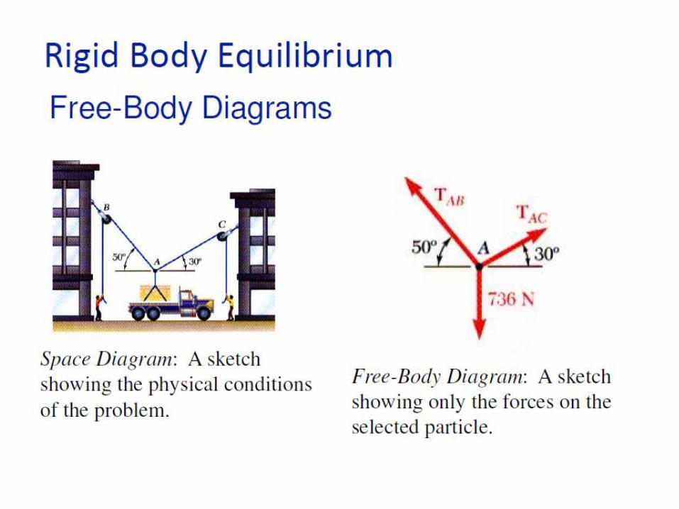
MODELING THE ACTION OF FORCES IN TWO-DIMENSIONAL ANALYSIS

5

6

7

Steps for Free-Body Diagrams
8

9

10

11

12

13

14

15

16
3.1 Determine the magnitudes of the forces C and T, which, along with the
other three forces shown, act on the bridge-truss joint

Solution 3.1
17

18
Calculate the tension T in the cable which supports the 500-kg mass with
the pulley arrangement shown. Each pulley is free to rotate about its bearing,
and the weights of all parts are small compared with the load. Find the
magnitude of the total force on the bearing of pulley C

19
The free-body diagram of each pulley is drawn in its relative position
to the others. We begin with pulley A, which includes the only known force.
With the unspecified pulley radius designated by r, the equilibrium of moments
about its center O and the equilibrium of forces in the vertical direction require
From the example of pulley A we may write the
equilibrium of forces on pulley B by inspection as
For pulley C the angle 30 in no way affects the
moment of T about the center of the pulley, so that
moment equilibrium requires

20
Clearly the radius r does not influence the results. Once we have analyzed a
simple pulley, the results should be perfectly clear by inspection.

21
Determine the magnitude T of the tension in the supporting cable and
the magnitude of the force on the pin at A for the jib crane shown. The
beam AB is a standard 0.5-m I-beam with a mass of 95 kg per meter of
length

22
The weight of the beam is 95(103)(5)9.81 4.66 kN and acts through its
center

23

24

25
26

27
The uniform 7-m steel shaft has a mass of 200 kg and is supported by a ball
and-socket joint at A in the horizontal floor. The ball end B rests against the
smooth vertical walls as shown. Compute the forces exerted by the walls
and the floor on the ends of the shaft

28
The free-body diagram of the shaft is first drawn where the contact
forces acting on the shaft at B are shown normal to the wall surfaces.
In addition to the weight
W =mg= 200(9.81)= 1962 N,
The vertical position of B
We will use A as a moment center to eliminate
reference to the forces at A. The position
vectors needed to compute the moments
about A are

29

30

31
The welded tubular frame is secured to the horizontal x-y plane by a
socket joint at A and receives support from the loose-fitting ring at B. Under
the action of the 2-kN load, rotation about a line from A to B is prevented by
the cable CD, and the frame is stable in the position shown. Neglect the
weight of the frame compared with the applied load and determine the
tension T in the cable, the reaction at the ring, and the reaction components
at A.

32
The direction of AB is specified by the unit
The moment of T about AB is the component in the direction of
AB of the vector moment about the point A
and equals Similarly the moment of the applied load F about AB

33
The moment equation now becomes

34

2
Structures: Difference between trusses, frames and beams,
Assumptions followed in the analysis of structures; 2D truss; Method of joints; Method of section;

3
Structures can be classified according to their
geometrical shape and the loads acting on them
Bar or a Rod: A slender structural element (cross-sectional
dimensions much smaller than its length) that is loadedsolely in the axial direction (tension or compression)
Beam: If the same geometrical object is subjected to a load
perpendicular to its axis
A curved beam is usually designated as an arch.
Structures consisting of inclined, rigidly joined beams
are called frames

4
A plane structure with a thickness much smaller than its
characteristic in-plane length is called a disk if it is solely
loaded in its plane, e.g., by in-plane forces
If the same geometrical structure is loaded perpendicularly
to its mid-plane it is called a plate.
If such a structure is curved it is a shell

5

6
A truss is a structure composed of slender members that are connected
at their ends by joints. The truss is one of the most important structures
in engineering applications
A framework composed of members joined at their ends to form a rigid
structure is called a truss.
Bridges, roof supports, derricks, and other such structures are common
examples of trusses
Structural members commonly used are I-beams, channels, angles,
bars, and special shapes which are fastened together at their ends by
welding, riveted connections, or large bolts or pins
When the members of the truss lie essentially in a single plane, the truss
is called a plane truss

7
I-BeamChannel
Angle
Bar Boxwire

8
The basic element of a plane truss is the triangle. Three bars joined
by pins at their ends, Fig. a, constitute a rigid frame. The term rigid is used to
mean non-collapsible and also to mean that deformation of the members due to
induced internal strains is negligible.
On the other hand, four or more bars pin-jointed to form a polygon of as
many sides constitute a nonrigid frame

9

10

11

12

13
14
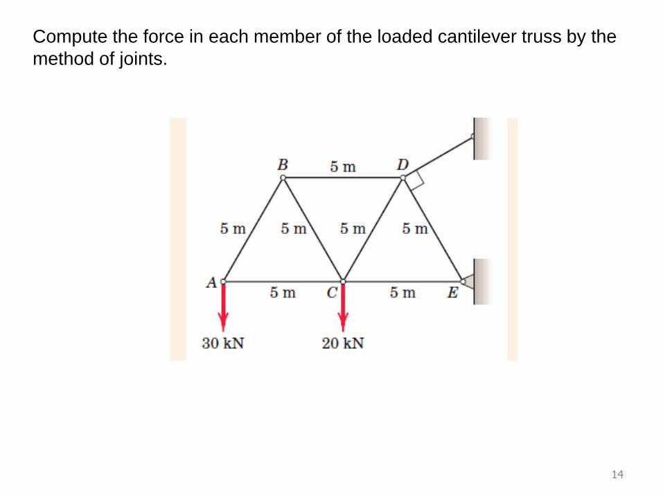
Compute the force in each member of the loaded cantilever truss by the
method of joints.

15
The first step will be to compute the external
forces at D and E from the free-body diagram of
the truss as a whole.
Next we draw free-body diagrams showing the forces acting on each of the
connecting pins. The correctness of the assigned directions of the forces is verified
when each joint is considered in sequence.

16

17
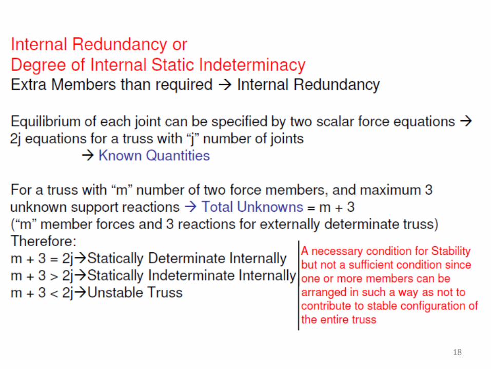
Statically Determinate TrussesA structure is called statically determinate if the support reactions can
be calculated from the three equilibrium conditions
18

19

20

21
22

23

24
The truss shown in Fig. a is loaded by an external force F. Determine the
forces at the supports and in the members of the truss

25

26

27

28

29

30

31

32
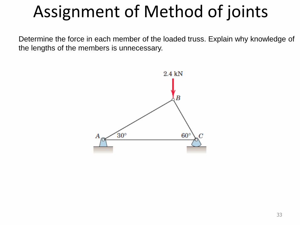
Assignment of Method of joints
33
Determine the force in each member of the loaded truss. Explain why knowledge of
the lengths of the members is unnecessary.
34
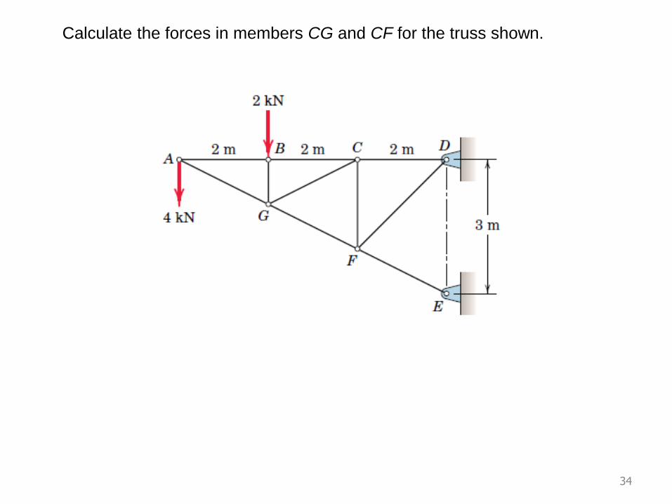
Calculate the forces in members CG and CF for the truss shown.
35
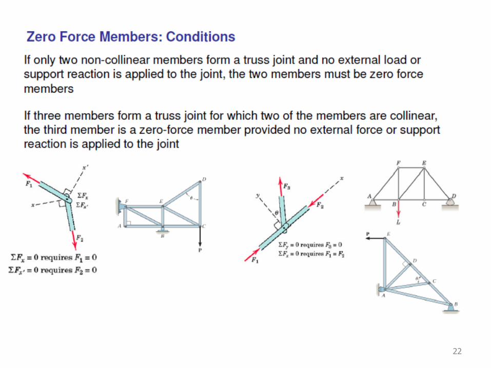
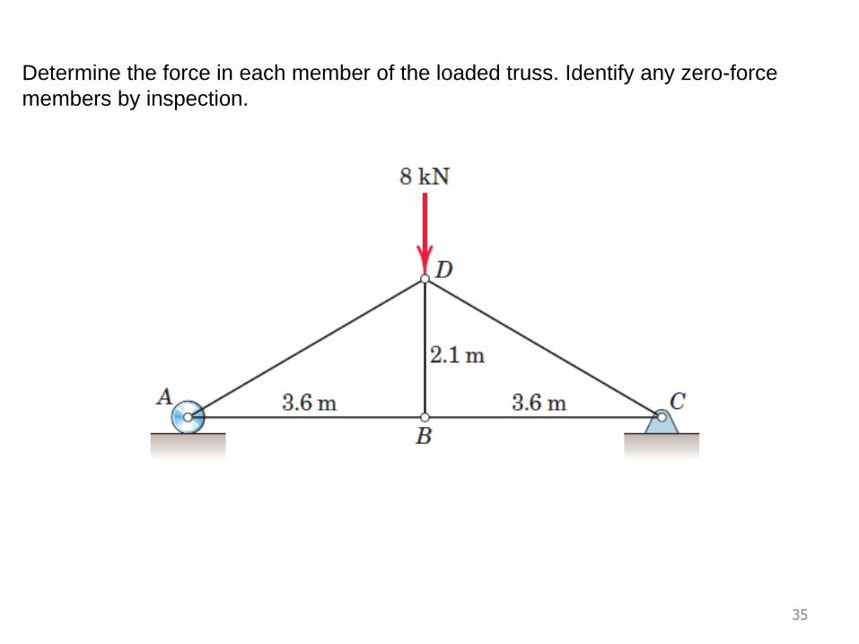
Determine the force in each member of the loaded truss. Identify any zero-force
members by inspection.
36
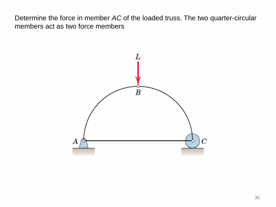
Determine the force in member AC of the loaded truss. The two quarter-circular
members act as two force members

1
Engineering Mechanics: ME101
Statics: Lecture 6
21th Jan 2016
Dr. Poonam Kumari
Department of Mechanical EngineeringIndian Institute of Technology Guwahati
D Block : Room No 201 : Tel: 3434

2

3

4

5

6
A truss is loaded by two forces, F1 = 2F and F2 = F, as shown in Fig. a.
Determine the force S4.

7
First, we determine the forces at the supports. Applying
the equilibrium conditions to the free-body diagram of
the whole truss yields

8
The unknown force S4 follows from the moment equation about point I (intersection
of the action lines of the forces (S5 and S6) of the free-body diagram on the left-hand
side of
The corresponding moment equation for the free-body diagram
on the right-hand side may be used as a check

9
Calculate the forces induced in members KL, CL, and CB by the 200-kN
load on the cantilever truss

10

11
Determine the forces in members CG and GH.
Assignment of method of Sections

12
Determine the force in member AE of the loaded truss

13

14