Embed Size (px)
Citation preview

Modeling the 14.5 mm BS41 projectile for ballistic impact computations
T. J. Holmquist1, G. R. Johnson1 & W. A. Gooch2 1Network Computing Services, Inc., Minneapolis, MN, U.S.A. 2U S Army Research Laboratory, Aberdeen Proving Ground, MD, U.S.A.
Abstract
This article presents the characterization and modeling of the U. S. Army Research Laboratory (ARL) 14.5 mm BS41 projectile for ballistic impact conditions. The ARL BS41 is a complex projectile that includes a steel case, inert filler materials, and an armor piercing tungsten carbide (WC) core. The characterization of the WC core is the focus of this work. The core material is a composite comprised of 93% WC and 6% cobalt (Co) and behaves like a very strong metal with little ductility. An approach is presented that determines Johnson-Cook strength and fracture model constants for the WC core using limited laboratory data along with ballistic impact experiments. Numerous 2D computations are presented (including experimental results) that demonstrate the response of the BS41 and the ability to model its behaviour. Keywords: tungsten carbide, cobalt, BS41 projectile, strength, fracture, ballistic performance, ballistic experiments.
1 Introduction and background
The former Soviet, and now Russian, 14.5 mm heavy machine gun is widely proliferated worldwide, predominately on wheeled combat vehicles. The original BS41 was developed by the Soviet Union and fielded in 1941 for use in the PTRD-41 bolt-action antitank rifle. The first U. S. surrogates of the Soviet BS41 were made in 1961 with a second lot produced in 1985. The surrogates were produced by Brass Extrusion Laboratories of Bensenville, IL. These projectiles were used domestically for many decades for armor development, and for ballistic acceptance testing for steel, aluminum and titanium armor plates. The 30,000 projectiles produced, have now all been depleted in domestic testing.
© 2005 WIT Press WIT Transactions on Modelling and Simulation, Vol 40, www.witpress.com, ISSN 1743-355X (on-line)
Computational Ballistics II 61

Recently, a new ARL BS41 surrogate was produced by New Lenox Machine Company of Dwight, IL to replenish the supply. ARL modified the original surrogate design by replacing the incendiary filler with an inert powder that allows for storage outside of explosive bunkers. The original surrogate and the new ARL BS41 are shown in fig. 1. The ballistic performance of the new ARL BS41 is the same as that of the original surrogate [1].
Figure 1: The original, and new, 14.5 mm BS41 surrogate projectile.
Figure 2: Schematic of the ARL 14.5 mm BS41 projectile.
Original BS41 surrogate produced by Brass Extrusion Laboratories
New ARL BS41 surrogate produced by New Lenox Machine Company
Tungsten carbide core (38.2 g rams)(93% W C, 6% cobalt)
Steel case (12.0 grams)
Lead filler (11.5 grams)
52 m
m
14.9 mm
34 m
m
10.9 mm
Inert powder (1.9 grams)
ARL BS41 project ile mass = 63.6 grams
© 2005 WIT Press WIT Transactions on Modelling and Simulation, Vol 40, www.witpress.com, ISSN 1743-355X (on-line)
62 Computational Ballistics II

Recently, there has been interest in developing the capability to simulate the ballistic response of this projectile to aid in the design of new lightweight armor. The modeling challenge lies in the ability to accurately represent the behaviour of the WC core material. A schematic of the ARL 14.5 mm BS41 projectile is presented in fig 2. The WC core is a composite material that falls under the category of “cemented carbides”, where hard carbide particles are bonded together by a metallic binder. The BS41 surrogate core is a cemented carbide comprised of 93% WC and 6% cobalt (the metallic binder). A characteristic of cemented carbides is their high strength and low ductility. It is this characteristic that makes the core a very good penetrator, but also a challenge to model. Because there is limited laboratory data available on the WC core, an approach using both laboratory data and ballistic experiments is used to determine the fracture model and constants. The remainder of this article describes the Johnson-Cook strength and fracture models, and the determination of constants for the WC core. It also presents a wide range of impact computations that are compared to experimental data. The computations are used to not only demonstrate good agreement with the experimental results, but to provide guidance in determining the facture model and constants.
2 The Johnson-Cook strength and fracture models
The Johnson-Cook strength and fracture models [2, 3] have been used to describe the strength and fracture responses of metals for nearly 20 years. The advantages of these models are that they are easy to understand, straightforward to implement into computer codes, and the constants can generally be determined explicitly. The Johnson-Cook (JC) strength model is expressed as
]1][ln1][[ ** MNp TCBA −++= εεσ (1)
where pε is the equivalent plastic strain, oεεε =* is the dimensionless
equivalent strain rate for 10.1 −= soε and T* is the homologous temperature. The five material constants are A, B, N, C, and M. The expression in the first set of brackets gives the stress as a function of strain. The expressions in the second and third brackets provide the strain rate effect and thermal softening effect respectively. The Johnson-Cook (JC) fracture model is given by
]1][ln1][exp[ *5
*4
*321 TDDDDD p
fp +++= εσε (2)
where fpε is the equivalent plastic strain at fracture, *
pε is the dimensionless
equivalent plastic strain rate, σσσ m=* is the dimensionless pressure-stress
ratio where mσ is the average of the three normal stresses (pressure) and σ is
© 2005 WIT Press WIT Transactions on Modelling and Simulation, Vol 40, www.witpress.com, ISSN 1743-355X (on-line)
Computational Ballistics II 63

the von Mises equivalent stress. The homologous temperature, T*, is the same as that used in the strength model of eqn (1). The five material constants are D1, D2, D3, D4, and D5. Damage to the material is given by
∑∆
= fp
pDεε
(3)
where pε∆ is the increment of equivalent plastic strain during an integration
cycle, and fpε is the equivalent strain to fracture, under the current conditions of
strain rate, temperature, pressure, and equivalent stress, as defined in eqn (2). Fracture occurs when D = 1.0.
3 Determination of constants for tungsten carbide
A summary of the JC strength and fracture model constants for tungsten carbide (93%WC, 6%Co) is presented in Table 1. The mass, elastic and thermal properties are obtained from References 4 and 5. The following presents a discussion of how the pressure, strength, and fracture model constants are determined. Figure 3 shows the pressure, P, as a function of volumetric strain,
1−= oρρµ . The data are from plate impact experiments provided by Grady [6] and Marsh [7]. The pressure-volume response is represented using the Mie-Gruneisen Equation of State [8] as presented in fig. 3. For this paper, laboratory data that describe the stress-strain response of 93% WC – 6% Co were not available. Here, the stress-strain response is determined from plate impact experiments and analysis by Grady [6]. Figure 4a shows two plate impact experiments for a tungsten carbide containing 5.7% Co [6]. Also shown in fig. 4a is the computational result that reproduces the plate impact experiments (primarily the hardening response). The net axial stress-axial strain relationship, used by Grady to match the plate impact experiments, is shown in fig. 4b. The response in fig. 4b is converted to equivalent stress and equivalent plastic strain, and JC model constants (A, B, and N) are determined. The isothermal response (no thermal softening) is shown in fig. 5. It should be noted that the JC strength model for tungsten carbide is only for high strain rates (~ 105 s-1) because the response was determined from plate impact experiments and the strain rate constant C = 0. Because the tungsten carbide characterization is for the BS41, and will be used for ballistic impact computations, using a high rate response is reasonable. The thermal softening constant is M = 1.0 and is determined from data from reference [5]. Laboratory data that address the fracture response of tungsten carbide are also not available, but many ballistic experiments are. The approach taken herein is to perform computations of various ballistic experiments (using different fracture models), compare the results, and use the fracture model that best represents the experimental behaviour. Because tungsten carbide is extremely brittle, two
© 2005 WIT Press WIT Transactions on Modelling and Simulation, Vol 40, www.witpress.com, ISSN 1743-355X (on-line)
64 Computational Ballistics II

fracture models are considered; the JC fracture model (using three sets of constants) and a maximum tensile stress model that fails the material when the maximum principal tensile stress, σ T, is exceeded. Figure 6 shows the JC fracture model using the three sets of constants investigated. Because there is little laboratory data available on the fracture response of WC, the model is simplified to two parameters (D2 and D3), where D1 = D4 = D5 = 0. Three different D3 constants are defined (D3 = –1.5, –3.0, and –5.0) and the remaining constant, D2, is determined by requiring that each response pass through the fracture strain resulting from a uniaxial stress compression test. The fracture strain is f
pε = .0052 determined by substituting in the fracture stress,
σc = 5.9 GPa reported by Grady [6], into the JC strength equation presented in fig. 5 and solving (assuming no strain rate effects). For the maximum tensile stress model, the spall stress is used (σT = σspall = 2.7 GPa) as reported by Grady [6]. The JC fracture model, using the constants D2 = 0.0019 and D3 = –3.0, produce the best overall results, as will be discussed in the following section.
Table 1: Tungsten carbide constants for the JC strength and fracture models.
Mass/Elastic/Thermal p ropertiesDensity = 14770 kg/m3
Hugoniot Elastic Limit = 4.1 GPaYoung’s Modulus = 620 GPaShear Modulus = 255 GPaBulk Modulus = 362 GPaPoisson’s Ratio = 0.215Melt Temperature = 1768 KSpecific Heat = 250 J/kg KThermal Conductivity = 95 W/m KVolumetric Thermal Expansion = .000015 K-1
Strength Constants for the Johnson-Cook ModelYield Stress, A = 3.0 GPaHardening Coefficient, B = 89.0 GPaHardening Exponent, N = 0.65Strain Rate Coefficient, C = 0.0Thermal Softening Exponent, M = 1.0
Equation of State Constants for the Mie-Gruneisen ModelK1 = 362 GPaK2 = 694 GPaK3 = 0 GPaGruneisen Coefficient, Γ = 1.0
Fracture Constants for the Johnson-Cook ModelD1 = 0.0D2 = 0.0019D3 = -3.0D4 = 0.0D5 = 0.0
© 2005 WIT Press WIT Transactions on Modelling and Simulation, Vol 40, www.witpress.com, ISSN 1743-355X (on-line)
Computational Ballistics II 65

Figure 3: Pressure vs. volumetric strain for tungsten carbide.
4 Computations
The following computations are performed using the 2003 version of the EPIC code, using 2D Lagrangian finite elements and 2D meshless particles [8, 9]. All the computations use the ARL BS41 projectile as defined in fig. 2. The materials are obtained from the EPIC material library with the exception of tungsten carbide. The tungsten carbide is modeled using the parameters from Table 1, with variations in the fracture model as discussed in Section 3. The initial grid uses five sets of crossed triangular elements (four triangles in a quad) across the radius of the tungsten carbide core. The grid sizes in the targets are similar to those used in the projectile core. Four different experiments are simulated. The first experiment investigates the semi-infinite penetration of a 4340 steel target by the ARL BS41 at an impact velocity of 1000 m/s. In the experiment, the steel case, lead filler, and inert powder were stripped away during penetration and the tungsten carbide core penetrated the steel target as a rigid body. The core penetrated to a depth of approximately 43 mm [1]. The experiment was very repeatable and the tungsten carbide core was always intact. Figure 7 presents the computed results for all four cases (three JC responses and the max tension response). Damage is shown at t = 25, 50, and 100 µs after impact. It is clear that the only two fracture responses that produce rigid body penetration are the JC model with D3 = –3.0 and the maximum tensile stress. The JC model with D3 = –1.5 results in fracture of the core early in the penetration process which indicates the model is too brittle in the high pressure-stress ratio region. Alternatively, the JC model with D3 = –5.0, produces rigid body penetration early in the computation, but eventually totally fractures (t = 100 µs) which indicates that the model is too brittle in the low pressure-stress ratio region. Because of these results, the JC
0
50
100
150
200
250
0 0.1 0.2 0.3 0.4
P = 362µ + 694µ2
Pres
sure
, P(G
Pa)
µ = ρ/ρo -1
LANL shock Hugoniot data (5% Co) (ρ = 15013 kg/m3)
Grady (5.7% Co) (ρ = 14930 kg/m3)
© 2005 WIT Press WIT Transactions on Modelling and Simulation, Vol 40, www.witpress.com, ISSN 1743-355X (on-line)
66 Computational Ballistics II

model using D3 = –3.0 and the maximum tensile stress will be the only responses investigated in the following computations.
Figure 4: a) Particle velocity time histories for two plate impact experiments and one computation using tungsten carbide. b) Net stress-axial strain response used to match the plate impact experiments.
Figure 8 presents computed results (showing damage) for the ARL BS41 impacting a 25.4 mm high hard armor steel plate at 700 m/s and 800 m/s. At 700 m/s the core is stopped in the steel plate when using the JC model, but perforates with a residual velocity, Vr = 139 m/s when using the maximum tensile stress. At 800 m/s the core exits the plate at 262 m/s and 373 m/s for the JC model and maximum tensile stress respectively. The experiment resulted in a ballistic limit of approximately 750 m/s [1]. The JC model produces results that are closer to the experiment. The maximum tensile stress appears too strong.
400
300
200
100
0
Parti
cle
velo
city
( m/s
)
0.90 0.95 1.00 1.05 1.10 1.15
Time (µs)
Test data (Grady)
Computation (Grady)
Stre
ss, σ
z, P
( GPa
)
12.0
8.0
4.0
00 0.005 0.010
Axial strain, εz
0.015 0.020
Net axial stress-axial strain (σz – εz) relationship used to match wave profile (Grady)
Mean stress (pressure, P)
HEL
HEL
a.
b.
Hardening
© 2005 WIT Press WIT Transactions on Modelling and Simulation, Vol 40, www.witpress.com, ISSN 1743-355X (on-line)
Computational Ballistics II 67

Figure 5: JC strength model for tungsten carbide.
Figure 6: JC fracture model for WC using three sets of constants.
Figure 9 presents computed results for the ARL BS41 impacting a 12.7 mm silicon carbide ceramic plate backed by a 25.4 mm 5083 aluminum plate. Both damage and materials are shown for an impact velocity of 700 m/s and 800 m/s. At 700 m/s the core perforates the silicon carbide and stops approximately 6 mm into the aluminum when using the JC model, but perforates the aluminum when using the maximum tensile stress. At 800 m/s both models perforate the target. The maximum tensile stress produces a higher residual velocity (Vr = 469 m/s) and a longer residual core (Lr = 26 mm) than that produced using the JC model.
0.0
2.0
4.0
6.0
8.0
10.0
12.0
0 0.01 0.02 0.03
Equivalent plastic strain, εp
Equi
vale
nt fl
ow s
tress
, σ(G
Pa)
σ = [3.0 + 89 εp0.65]
Isothermal response
0.00
00.00
40.00
80.01
2
-0.8 -0.4 0 0.4 0.8 1.2
Pressure-stress ratio, σ∗ = P/σ
Equi
vale
nt p
lastic
frac
ture
stra
in, ε
pf
Uniaxial stress compression test
)5.1(0032. *σε −= E X Pfp
)0.3(0019. *σε −= E X Pfp
)0052.( =fpε
)0.5(0010. *σε −= E X Pfp
© 2005 WIT Press WIT Transactions on Modelling and Simulation, Vol 40, www.witpress.com, ISSN 1743-355X (on-line)
68 Computational Ballistics II

Nine experiments (using the original BS41 surrogate at velocities from 717 m/s to 904 m/s) are presented in Table 2 [10]. The approximate ballistic limit is 750 m/s. Impact velocities below 750 m/s generally result in the core stopping in the aluminum and velocities above 750 m/s result in target perforation. The JC model produces results that are closer to the experiment.
Figure 7: Computed results (showing damage) for the ARL BS41 projectile impacting a steel target at 1000 m/s. Results are presented for the JC fracture model using three sets of constants and a maximum tensile stress at t = 25, 50 and 100 µs after impact.
Experimental penetration depth (P = 43 mm)
Damage contours
4340 steel (Rc 30)
ARL BS41 project ileV = 1000 m/s
D = 0
0 < D < 0.50
0.50 < D < 1.0
D = 1.0
JC modelD3 = -1.5
t = 25 µs
t = 50 µs
t = 100 µs
P = 26 mm P = 48 mm P = 40 mm P = 48 mm
JC modelD3 = -3.0
JC modelD3 = -5.0
Max tensionσ Τ = 2.7 GPa
© 2005 WIT Press WIT Transactions on Modelling and Simulation, Vol 40, www.witpress.com, ISSN 1743-355X (on-line)
Computational Ballistics II 69

Figure 8: Computed results (showing damage, same scale as fig. 7) for the ARL BS41 projectile impacting a steel plate at 700 m/s and 800 m/s. Results are presented for the JC fracture, and a maximum tensile stress, model.
Table 2: Experimental data for the original BS41 surrogate impacting a silicon carbide tile backed by aluminum.
High hard armor steel (BHN 447) 25.4 mm
ARL BS41 project ileBallistic limit velocity = 750 m/s
Vr = 0 Vr = 139 m/s Vr = 262 m/s
V = 700 m/s V = 800 m/s
Vr = 373 m/s
Steel plug
Steel plug
JC modelD3 = -3.0
JC modelD3 = -3.0
Max tensionσΤ = 2.7 GPa
Max tensionσΤ = 2.7 GPa
9693
9696
9740
9739
9741
9695
9694
9692
9691
Shotnumber
ImpactVelocity
(m/s)
TotalYaw
(degree)
ResidualVelocity
(m/s)
Residual Length(mm)
ResidualMass
(grams)
Comment
717
739
741
746
750
764
775
816
904
1.27
0.90
1.41
1.90
0
1.75
0.25
1.90
1.75
----
----
----
237
----
6911167
< 67315295538512
----
----
----
8
----
13.68.68
10.712231810
----
----
----
NM
----
6.43.5NM3.7NMNMNMNM
NM = Not Measured
AluminumPenetration
(mm)
3
16
10
Perforat ion
6
Perforat ion
Perforat ion
Perforat ion
Perforat ion
3 mm bulgein aluminum6 mm bulgein aluminum3 mm bulgein aluminumCore
3 mm bulgein aluminumCorePlugCorePlugCore t ipCore ta ilCore t ipCore ta il
© 2005 WIT Press WIT Transactions on Modelling and Simulation, Vol 40, www.witpress.com, ISSN 1743-355X (on-line)
70 Computational Ballistics II

Figure 9: Computed results (showing damage, same scale as fig. 7, and material) for the ARL BS41 projectile impacting a silicon carbide backed by aluminum target at 700 m/s and 800 m/s. Results are presented for the JC fracture model and a maximum tensile stress model.
Figure 10 presents computed results for the ARL BS41 impacting a 12.7 mm aluminum nitride ceramic plate backed by a 6.35 mm 2024-T351 aluminum plate. The impact velocity is 850 m/s. Damage contours are presented at t = 40, 80 and 225 µs after impact for both the JC model and the maximum tensile stress model. At 40 µs the core is generally intact for the JC model, where the maximum tensile stress produces more fractured material in the core (especially in the tip). At 225 µs both have perforated the target. For the JC model, the core is generally intact where the maximum tensile stress produces much more fractured material. Figure 11 presents a comparison of the residual tungsten
5083 Aluminum (150 mm X 150 mm)
25.4 mm
BS41 project ileBallistic limit velocity = 750 m/s
12.7 mm
Silicon carb ide (100 mm X 100 mm)
V = 700 m/s V = 800 m/s
Vr = 0Vr = 186 m/sLr ~ 15 mm
Vr = 132 m/sLr ~ 12 mm
Vr = 469 m/sLr ~ 26 mm
Damage
Material
Aluminum penetration = 6 mm Plug
JC modelD3 = -3.0
JC modelD3 = -3.0
Max tensionσΤ = 2.7 GPa
Max tensionσΤ = 2.7 GPa
Plug
© 2005 WIT Press WIT Transactions on Modelling and Simulation, Vol 40, www.witpress.com, ISSN 1743-355X (on-line)
Computational Ballistics II 71

carbide core for the two computations, and from an experiment using the original BS41 surrogate [11]. At t = 225 µs after impact, the x-ray clearly shows the core tip intact, although the aft portion of the core appears fractured. The core resulting from the JC model is generally intact although the tip has separated from the body, and there appears to be substantial damage toward the rear. The maximum tensile stress results in a core that has no tip, with much of the rear portion having failed. At t = 525 µs after impact, the x-ray shows the core broken into many pieces with the tail still intact. The computed result using the maximum tensile stress model has not changed much from t = 225 µs, where the JC model produces a core broken into three pieces. Again, it appears that the response produced from the JC model is closer to the experimental result. Here, the maximum tensile stress model appears too weak, where it appeared too strong in the previous examples.
Figure 10: Computed results (showing damage, same scale as fig. 7) for the ARL BS41 projectile impacting an aluminum nitride backed by aluminum target at 850 m/s. Results are presented for the JC fracture model and a maximum tensile stress model at t = 40, 80 and 225 µs after impact.
2024-T351 Aluminum 12.7 mm
6.35 mm
Aluminum nitride
BS41 project ileV = 850 m/s
t = 40 µs
t = 80 µs
t = 225 µs
JC modelD3 = -3.0
Max tensionσΤ = 2.7 GPa
© 2005 WIT Press WIT Transactions on Modelling and Simulation, Vol 40, www.witpress.com, ISSN 1743-355X (on-line)
72 Computational Ballistics II
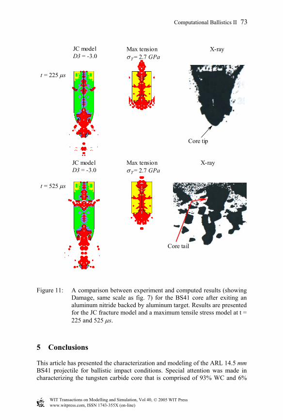
Figure 11: A comparison between experiment and computed results (showing Damage, same scale as fig. 7) for the BS41 core after exiting an aluminum nitride backed by aluminum target. Results are presented for the JC fracture model and a maximum tensile stress model at t = 225 and 525 µs.
5 Conclusions
This article has presented the characterization and modeling of the ARL 14.5 mm BS41 projectile for ballistic impact conditions. Special attention was made in characterizing the tungsten carbide core that is comprised of 93% WC and 6%
t = 225 µs
X-ray
t = 525 µs
X-ray
Core tip
Core tail
JC modelD3 = -3.0
Max tensionσΤ = 2.7 GPa
JC modelD3 = -3.0
Max tensionσΤ = 2.7 GPa
© 2005 WIT Press WIT Transactions on Modelling and Simulation, Vol 40, www.witpress.com, ISSN 1743-355X (on-line)
Computational Ballistics II 73

Co. JC strength model constants were obtained for tungsten carbide using results from plate impact experiments. The JC fracture model and a maximum tensile stress model were evaluated by performing numerous ballistic computations using the ARL BS41 surrogate projectile. The computed results were compared to experimental results produced using both surrogate BS41 projectiles. The JC fracture model produced the best overall response (when comparing results to experiments) and is the recommended model for the tungsten carbide used in the BS41 projectile.
Acknowledgement
This work was performed under Prime Contract No. F42620-00-D-0037-BR02. The authors would like to thank D. W. Templeton (U. S. Army Tank-Automotive Research, Development, and Engineering Center), C. E. Anderson Jr. (Southwest Research Institute), and M. S. Burkins (U. S. Army Research Laboratory) for their contributions to this work.
References
[1] Burkins, M., An evaluation of 14.5 mm AP surrogate projectiles. Presented at the Ground Vehicle Survivability Symposium, Monterey, CA, 2003.
[2] Johnson, G. R. & Cook, W. H., A constitutive model and data for metals subjected to large strains, high strain rates and high temperatures. Proceedings of the Seventh International Symposium on Ballistics, The Hague, Netherlands, 1983.
[3] Johnson, G. R. & Cook, W. H., Fracture characteristics of three metals subjected to various strains, strain rates, temperatures and pressures. Engineering Fracture Mechanics, Vol. 21, No. 1, pp. 31-48, 1985.
[4] Rapacki, E., Personal communication. December, 2003. [5] Sandvik Hard Materials, Understanding cemented carbides, Sandvik
technical brochure. [6] Grady, D., Impact failure and fragmentation properties of tungsten
carbide. International Journal of Impact Engineering, Vol 23, pp. 307-317, 1999.
[7] Marsh, S. P., LASL shock Hugoniot data. University of California press, 1980.
[8] Johnson, G. R., Stryk, R. A., Holmquist, T. J., & Beissel, S. R., Numerical algorithms in a Lagrangian hydrocode. Report No. WL-TR-1997-7039, Wright Laboratory, June, 1997.
[9] Johnson, G. R., Stryk, R. A., Beissel, S. R, &.Holmquist, T. J, Conversion of finite elements into meshless particles for penetration computations involving ceramic targets. Shock Compression of Condensed Matter-2001, ed. M. D. Furnish, N. N. Thadhani, and Y. Horie, 2002 AIP, pp. 1287-1290.
© 2005 WIT Press WIT Transactions on Modelling and Simulation, Vol 40, www.witpress.com, ISSN 1743-355X (on-line)
74 Computational Ballistics II

[10] Burkins, M. S., Unpublished ARL Ballistic Data, ARL EF110G, Shot Records 9691-9696 and 9739-9741, November 2002.
[11] Holmquist, T. J., Johnson, G. R., & McHenry, K. D., Light and reactive armor technology. Quarterly program report, January, 1994.
© 2005 WIT Press WIT Transactions on Modelling and Simulation, Vol 40, www.witpress.com, ISSN 1743-355X (on-line)
Computational Ballistics II 75