Embed Size (px)
Citation preview

VOL. 9, NO. 4, APRIL 2014 ISSN 1819-6608
ARPN Journal of Engineering and Applied Sciences
©2006-2014 Asian Research Publishing Network (ARPN). All rights reserved.
www.arpnjournals.com
398
MODELING, SIMULATION AND ANALYSIS OF A SCARA ROBOT FOR DEBURRING OF CIRCULAR COMPONENTS
PVS Subhashini1, N.V.S. Raju2 and G. Venkata Rao1
1Vasavi College of Engineering, Hyderabad, India 2JNTUH College of Engineering, Jagithayala, Andhra Pradesh, India
E-Mail: [email protected] ABSTRACT
Selective Compliance Assembly Robot Arm (SCARA) is an arm configuration obtained by the combination of articulated and cylindrical arm configurations. SCARA is widely utilized for various industrial applications where accuracy and precision are essential. In this paper, an analysis of SCARA robot as applied for deburring parts having circular profile and the deburring operation is fixed to a time period of 6 seconds is carried out. A complete mathematical model is carried out for kinematics and equations are derived using Denavit-Hartenberg notation. SCARA robot in the present case is modeled using CAD software and motion simulation is carried out. Different kinematic parameters include joint angles, positions, and velocities are calculated from CAD software and compared with the results obtained from MATLAB. It is observed that all the results match fairly closely. The reasons for deviations may be that while MATLAB solves the equations directly through symb olic language code, where as analysis by the other codes and software are carried out through numerical schemes. Keywords: SCARA, deburring, kinematics, inverse kinematics, MATLAB, D-H notation. Nomenclature LL1, LL2, LL4 Link length of main arm, forearm, quill (mm)
, , Joint angle or angular displacement of joint1, joint2, joint4 (radians or deg)
, , Angular velocity of joint1, joint2, joint4 (radians /s or deg/s)
, , Angular acceleration of joint1, joint2, joint4 (radians /s2 or deg/s2) INTRODUCTION
Modeling, simulation and analysis of a robot for manufacturing operations is an essential part of operations because experimentation with realistic models is time consuming and laborious. The possibility to perform real-time simulations becomes particularly important in the later stages of the design process. The final scheme can be verified before one embarks on the costly and time consuming process [1].
Simulation is important observational sequence as discussed in reference [1] for robot programmers to evaluate, predict the behavior of robot, in addition to verification and optimizing the path planning of the process [2]. Being able to simulate opens a wide range of options for solving many problems creatively. One can investigate, design, and test an object, even if it does not exist [3].
SCARA robotic arms are primarily used in situations where the process requires high accuracy, and has a fast cycle time, which is why SCARA robotic arms are popular as part of electronics equipment assembly lines. SCARA robotic arms have also been employed in various other industrial areas such as pick and place type operations, automated palletizing, and de-palletizing operations.
Alshamasin [4] investigated the simulation of robot systems which is getting very popular, this research, a complete mathematical model of SCARA robot was developed including servomotor dynamics and presented together with dynamic simulation. The equations of kinematics with DC servomotor driving each robot joint is studied and modeled. A SCARA robot was constructed to achieve drilling operation using solid dynamic software. The performance of robot-actuator system was examined with solid dynamic simulation and verified with MATLAB /Simulink.
Robot automation systems for the deburring process have been developed primarily for the automotive industry, kitchen products, and the manufacture of plastics. The deburring process, however, is a relatively undeveloped process and it is difficult to obtain a comprehensive list of the literature on the subject [5].
There are different robot arm configurations available like cartesian, cylindrical, polar and articulated robots. This paper is concentrated on SCARA robot applied to deburring operation of circular components. SCARA ROBOT
SCARA has four degree of freedom where three are revolute and one prismatic joint. The robot fabricated for this work has two stepper motors of 1.80 step angle for joints at link1 and link2 for revolute motion and DC motors of 10 rpm 12 volts DC geared motor 10kg-cm torque at link3 for prismatic and link4 revolution motion. The fabricated model of SCARA robot is shown in Figure-1.

VOL. 9, NO. 4, APRIL 2014 ISSN 1819-6608
ARPN Journal of Engineering and Applied Sciences
©2006-2014 Asian Research Publishing Network (ARPN). All rights reserved.
www.arpnjournals.com
399
Figure-1. SCARA robot.
Figure-2 shows the link base which is made of cast iron hollow pipe length of 220mm and diameter of 85mm. It is fixed to the wooden board with the help of angle brackets.
Figure-2. Base, Revolute link1.
Figure-3. Revolute link2.
Figure-4. Sliding link3 and deburring tool.
Figure-5. SCARA robot modeled in CAD software.
Revolute link1 is made of aluminum rectangular box section bar of dimension 230*75*25 (length * breath * height) mm. The centre to centre distance of the link is 155mm. Figure-3 shows revolute link2 which is made up of aluminum rectangular hollow section bar of dimension 230*75*25 (length * breath * height) mm. The centre to centre distance of the link is 160mm. Figure-4 shows Sliding link 3 is made up of aluminum rectangular hollow section bar of dimension 350*30*20 (length*breath*height) mm. The sliding limit of the link is 110mm and a link4 or end effector of deburring tool.
The SCARA robot described above is modeled using CAD software.CAD modeled SCARA robot is shown in Figure-5 for the specified deburring operations. Kinematics of a SCARA robot
The aspect of forward and inverse kinematics needs no emphasis by making use of the known Denavit-Hartenberg scheme; these are studied for the present case. Forward kinematics
Figure-6. D-H parameters for SCARA robot.

VOL. 9, NO. 4, APRIL 2014 ISSN 1819-6608
ARPN Journal of Engineering and Applied Sciences
©2006-2014 Asian Research Publishing Network (ARPN). All rights reserved.
www.arpnjournals.com
400
The Devavit-Hartenberg (D-H) parameters for SCARA robot are shown in Figure-6.
Each axis of the SCARA robot was numbered from 1 to 4. The αi is the rotation about Xi to make Zi−1 parallel with Zi. Starting from axis 1, α1 is 0 because Z0 and Z1 are parallel. For axis 2, the α2 is π or 180◦ because Z2 is opposite of Z0 which is pointing down along the translation of the prismatic joint. α3 and α4 values are zero because Z3 is parallel with Z2 and Z4 is also parallel with Z3. The next step is to determine ai and di. For axis 1, there is an offset d1 between axes 1 and 2 in the Z0 direction. There is also a distance a1 between both axes. For axis 2, there is a distance a2 between axes 2 and 3 away from the Z1 axis. No offset is found in this axis so d2 is zero. In axis 3, due to prismatic joint, the offset d3 is variable. Between axes 3 and 4, there is an offset d4 which is equal to this distance, while a3 and a4 are zero. The completed D-H parameters are listed in Table-1.
Table-1. D-H parameters of the SCARA robot.
Axis No. (i)
Joint angle (θi)
Link offset (di)
Link length
(ai)
Twist angle (αi)
1 0 LL1 0 2 0 LL2 0 3 0 d3 0 0 4 LL4 0 0
(1)
(2)
(3)
(4)
(5)
Inverse kinematics of the robot Required location of the gripper of SCARA robot
Te = (6)
The final equation representing the robot is:
(7) To solve for the joint angles
(8)
(9)
(10)
(11)
(12)
(13)
Velocity equations of the robot
(14)
(15) d3 = -Pz (16)
(17)
Acceleration equations of the robot
(18)
(19)
(20)
(21)
VOL. 9, NO. 4, APRIL 2014 ISSN 1819-6608
ARPN Journal of Engineering and Applied Sciences
©2006-2014 Asian Research Publishing Network (ARPN). All rights reserved.
www.arpnjournals.com
401
Assumptions In view of the very small magnitudes of cutting
forces during deburring, the interaction of the end effector on the environment is neglected. SIMULATION AND ANALYSIS
Different kinematic and dynamic analysis equations are coded in to the MATLAB software. Also the assembled model in Unigraphics is simulated for carrying out the chosen circular path. The input parameters are Link lengths are LL1= 250mm LL2= 150mm and quill velocity of 60 Degree/s.
The application of SCARA robot is for deburring a circular component where the center of circular component is kept at a distance of 340mm from the base, the base being at (0,0) of the coordinate system. Radius of the circular component is varied as 30mm, 40mm, 50mm and motion analysis done, all with time constraint of 6seconds.
Different links like base, link1, link2, link3, end effector are modeled, assembled and simulated in Unigraphics CAD software.
Different kinematic parameters include angular displacement, angular velocity are recorded from the Unigraphics motion simulation. Using the mathematical equations of section (4) the different parameters are calculated in MATLAB. RESULTS AND DISCUSSIONS Circular shape component of diameter = 60mmm
Using the Unigraphics software and MATLAB the end effector positions in X and Y is shown in Figure-7 which represents the deburring in circular shape.
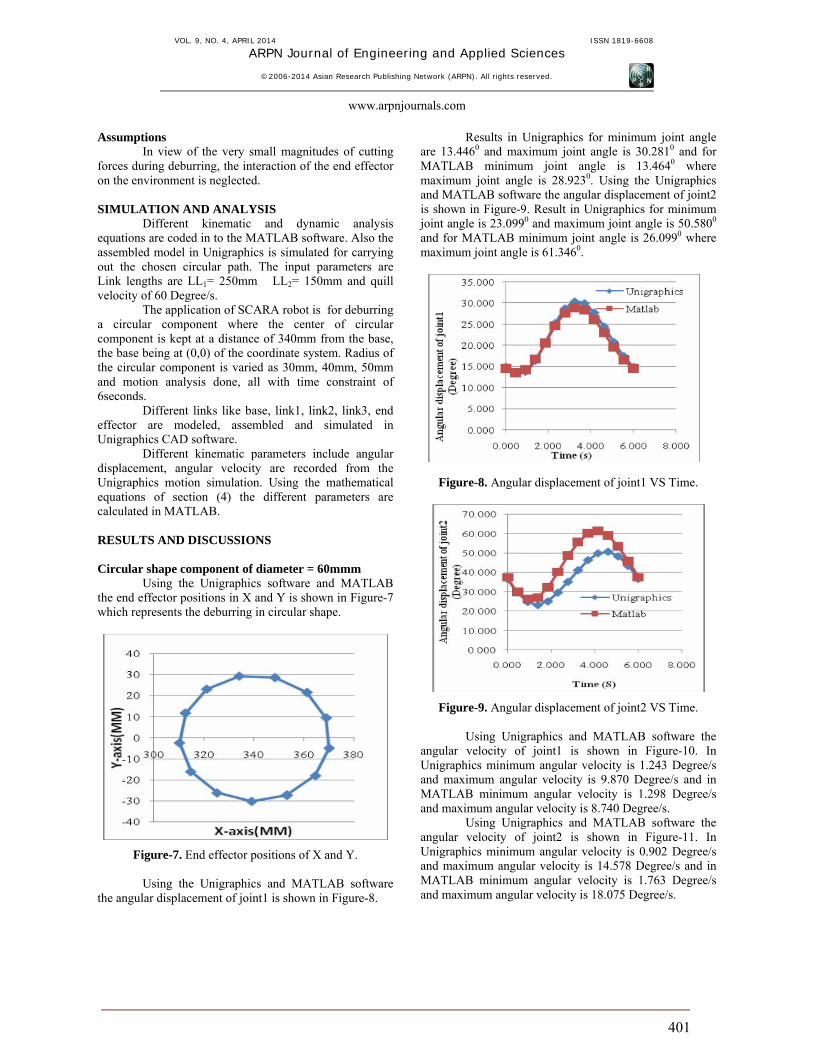
Figure-7. End effector positions of X and Y. Using the Unigraphics and MATLAB software
the angular displacement of joint1 is shown in Figure-8.
Results in Unigraphics for minimum joint angle are 13.4460 and maximum joint angle is 30.2810 and for MATLAB minimum joint angle is 13.4640 where maximum joint angle is 28.9230. Using the Unigraphics and MATLAB software the angular displacement of joint2 is shown in Figure-9. Result in Unigraphics for minimum joint angle is 23.0990 and maximum joint angle is 50.5800
and for MATLAB minimum joint angle is 26.0990 where maximum joint angle is 61.3460.
Figure-8. Angular displacement of joint1 VS Time.
Figure-9. Angular displacement of joint2 VS Time.
Using Unigraphics and MATLAB software the angular velocity of joint1 is shown in Figure-10. In Unigraphics minimum angular velocity is 1.243 Degree/s and maximum angular velocity is 9.870 Degree/s and in MATLAB minimum angular velocity is 1.298 Degree/s and maximum angular velocity is 8.740 Degree/s.
Using Unigraphics and MATLAB software the angular velocity of joint2 is shown in Figure-11. In Unigraphics minimum angular velocity is 0.902 Degree/s and maximum angular velocity is 14.578 Degree/s and in MATLAB minimum angular velocity is 1.763 Degree/s and maximum angular velocity is 18.075 Degree/s.

VOL. 9, NO. 4, APRIL 2014 ISSN 1819-6608
ARPN Journal of Engineering and Applied Sciences
©2006-2014 Asian Research Publishing Network (ARPN). All rights reserved.
www.arpnjournals.com
402
Figure-10. Angular velocity of joint1 VS Time.
Figure-11. Angular velocity of joint1 VS Time (UG). Circular shape component of diameter = 80mmm
End effector positions in X and Y is shown in Figure-12.
Using the Unigraphics and MATLAB software the angular displacement of joint1 is shown in Figure-13. In Unigraphics minimum joint angle is 9.6000 and maximum joint angle is 32.7360 and in MATLAB minimum joint angle is 10.3230 and maximum joint angle is 31.2630. Using the Unigraphics and MATLAB software the angular displacement of joint1 is shown in Figure-14. In Unigraphics minimum joint angle is 16.3650 and maximum joint angle is 54.480 and in MATLAB minimum joint angle is 17.4930 and maximum joint angle is 66.0220.
300 310 320 330 340 350 360 370 380 390-50
-40
-30
-20
-10
0
10
20
30
40
X-axis(MM)
Y-a
xis(
MM
)
Figure-12. End effector positions of X and Y.
Figure-13. Angular displacement of joint1 VS Time.
Figure-14. Angular displacement of joint2 VS Time.

VOL. 9, NO. 4, APRIL 2014 ISSN 1819-6608
ARPN Journal of Engineering and Applied Sciences
©2006-2014 Asian Research Publishing Network (ARPN). All rights reserved.
www.arpnjournals.com
403
Figure-15. Angular velocity of joint1 VS Time.
Using Unigraphics and MATLAB software the angular velocity of joint1 is shown in Figure-15. In Unigraphics minimum angular velocity is 3.133 Degree/s and maximum angular velocity is 14.579 Degree/s and in MATLAB minimum angular velocity is 1.303 Degree/s and maximum angular velocity is 12.133 Degree/s.
Using Unigraphics and MATLAB software the angular velocity of joint1 is shown in Figure-16. In Unigraphics minimum angular velocity is 3.323 Degree/s and maximum angular velocity is 21.579 Degree/s and in MATLAB minimum angular velocity is 3.020 Degree/s and maximum angular velocity is 25.339 Degree/s.
Figure-16. Angular velocity of joint2 VS Time. Circular component of diameter = 100mm
End effector positions in X and Y is shown in Figure-17.
290 300 310 320 330 340 350 360 370 380 390-60
-40
-20
0
20
40
60
X-axis(MM)
Y-a
xis(
MM
)
Figure-17. End effector positions of X and Y.
Figure-18. Angular displacement of joint1 VS Time.
Using the Unigraphics and MATLAB software, the angular displacement of joint1 is shown in Figure-18. In Unigraphics minimum joint angle is 1.7460 and maximum joint angle is 35.1600 and in MATLAB minimum joint angle is 6.6900 and maximum joint angle is 33.5830. Using the Unigraphics and MATLAB software the angular displacement of joint2 is shown in Figure-19. In Unigraphics minimum joint angle is 1.7460 and maximum joint angle is 35.1600.and in MATLAB minimum joint angle is 6.6900 and maximum joint angle is 33.5830.
Figure-19. Angular displacement of joint2 VS Time.

VOL. 9, NO. 4, APRIL 2014 ISSN 1819-6608
ARPN Journal of Engineering and Applied Sciences
©2006-2014 Asian Research Publishing Network (ARPN). All rights reserved.
www.arpnjournals.com
404
Using Unigraphics and MATLAB software the angular velocity of joint1 is shown in Figure-20. In Unigraphics minimum angular velocity is 1.959 Degree/s and maximum angular velocity is 22.174 Degree/s and in MATLAB minimum angular velocity is 2.0411 Degree/s and maximum angular velocity is 22.0138 Degree/s.
Figure-20. Angular velocity of joint1 VS Time.
Using Unigraphics and MATLAB software the angular velocity of joint1 is shown in Figure-21. In Unigraphics minimum angular velocity is 2.590 Degree/s and maximum angular velocity is 31.190 Degree/s and in MATLAB minimum angular velocity is 0.513 Degree/s and maximum angular velocity is 31.037 Degree/s.
Figure-21. Angular velocity of joint2 VS Time. CONCLUSIONS
SCARA robot is modeled and simulated in CAD software for deburring operation of circular component. Mathematical equations are modeled using D-H parameters and kinematic equations are derived. Angular displacement and angular velocity of joint1 and joint2 with respect to time are discussed for the specific case of deburring of circular components. Kinematic parameters of SCARA robot are compared using CAD software and MATLAB.
It is observed that all the results match fairly closely with one exception. Angular displacement for joint2 is differing especially towards end of travel. The difference in the values may be due to the differences in modeling the geometry. Also, MATLAB solves the equations directly through symbolic language code, while analysis is by the other codes and software are carried out through numerical schemes. These studies are to be corroborated with actual cutting trials later using the manufactured robot. REFERENCES [1] Kazi, A., G. Merk, M. Otter, and H. Fan. 2002.
Design optimization of industrial robots using the Modelica multi-physics modeling language. Proceedings of the 33rd ISR (International Symposium on Robotics), October 7 - 11.
[2] Ionescu Fl., F. Chojnowski and G. Constantin. 2002.
Virtual Reality in Mechanical Engineering, Modelling and Simulation with Solid Dynamics. ARA-Journal. 1: 27.
[3] Leon Zlajpah. 2008. Simulation in robotics.
ScienceDirect, Mathematics and Computers in simulation. 79: 879-897.
[4] Mahdi Salman Alshamasin, Florin Ionescu and Riad
Taha Al-Kasasbeh. 2009. Kinematic modeling and simulation of a SCARA robot by using solid dynamics and Verification by Matlab / Simulink. European Journal of Scientific Research. ISSN 1450-216X. 37(3): 388-405.
[5] Beom-Sahng Ryuh and Gordon R. Pennock. 2006.
Robot Automation Systems for deburring. pp. 609-622.
[6] RK Mittal and IJ Nagarath. 2005. Robotics and
Control. Tata Mcgraw-Hill Publications. pp. 95-98, 126-128.
[7] Saeed B.Niku. 2001. Introduction to robotics analysis,
systems, applications. Prentice Hall Inc., Upper Saddle River, New Jersey, USA.