Embed Size (px)
Citation preview
J. Chem. Phys. 154, 104704 (2021); https://doi.org/10.1063/5.0041070 154, 104704
© 2021 Author(s).
Modeling oil–water separation withcontrolled wetting propertiesCite as: J. Chem. Phys. 154, 104704 (2021); https://doi.org/10.1063/5.0041070Submitted: 18 December 2020 . Accepted: 17 February 2021 . Published Online: 08 March 2021
Cristina Gavazzoni, Marion Silvestrini, and Carolina Brito
COLLECTIONS
Paper published as part of the special topic on Special Collection in Honor of Women in Chemical Physics and
Physical Chemistry
The Journalof Chemical Physics ARTICLE scitation.org/journal/jcp
Modeling oil–water separation with controlledwetting properties
Cite as: J. Chem. Phys. 154, 104704 (2021); doi: 10.1063/5.0041070Submitted: 18 December 2020 • Accepted: 17 February 2021 •Published Online: 8 March 2021
Cristina Gavazzoni,a) Marion Silvestrini, and Carolina Brito
AFFILIATIONSInstituto de Física, Universidade Federal do Rio Grande do Sul, Caixa Postal 15051, CEP 91501-970 Porto Alegre,Rio Grande do Sul, Brazil
Note: This paper is part of the JCP Special Collection in Honor of Women in Chemical Physics and Physical Chemistry.a)Author to whom correspondence should be addressed: [email protected]
ABSTRACTSeveral oil–water separation techniques have been proposed to improve the capacity of cleaning water. With the technological possibility ofproducing materials with antagonist wetting behavior, for example, a substrate that repels water and absorbs oil, the understanding of theproperties that control this selective capacity has increased with the goal of being used as the mechanism to separate mixed liquids. Besidesthe experimental advance in this field, less is known from the theoretical side. In this work, we propose a theoretical model to predict thewetting properties of a given substrate and introduce simulations with a four-spin cellular Potts model to study its efficiency in separatingwater from oil. Our results show that the efficiency of the substrates depends both on the interaction between the liquids and on the wettingbehavior of the substrates itself. The water behavior of the droplet composed of both liquids is roughly controlled by the hydrophobicityof the substrate. Predicting the oil behavior, however, is more complex because the substrate being oleophilic does not guarantee that thetotal amount of oil present on the droplet will be absorbed by the substrate. For both types of substrates considered in this work, pillaredand porous with a reservoir, there is always an amount of reminiscent oil on the droplet, which is not absorbed by the substrate due to theinteraction with the water and the gas. Both theoretical and numerical models can be easily modified to analyze other types of substrates andliquids.
Published under license by AIP Publishing. https://doi.org/10.1063/5.0041070., s
I. INTRODUCTION
Water separation and purification methods have been widelystudied due to environmental, economical, and social issues.1–4 Par-ticularly, there is an increased level of attention focused in oil–waterseparation techniques mainly due to oil being the most common pol-lutant in the world, principally from oil spill accidents and industryoily waste water.5–7
Oil/water mixtures can be classified in two different waysdepending on the diameter d of the dispersed phase: stratifiedoil/water (d > 20 μm) and emulsified oil/water (d < 20 μm).8
Depending on the type of the mixture, different techniques are usedin order to separate oil from water.9
Gravity separation followed by skimming is typically used toremove stratified oil from water and is considered an efficient,low cost, and primary step in water treatment.10,11 For smaller oil
droplets, these approaches are not effective, and follow-up steps intreatment are often required. Some of the conventional techniquesused to treat emulsions are chemical emulsification,12 centrifuga-tion,13,14 heat treatment,15 and membrane filtration.3,9 Limitations ofthese conventional approaches include high energy costs, operatingcosts, sludge production, and limited efficiency.7
Recently, the role of wettability has been studied in order topropose more efficient and low costs water/oil separation methods.The wetting behavior of a certain surface will depend on the geom-etry and chemistry of the substrate,16–18 and thus, by controllingthese key parameters, one can develop a material with antagonis-tic wetting behavior for oil and water that propitiates the mixtureseparation.
With that in mind, several materials with special wetting behav-ior were developed and successfully applied in oil–water separa-tion. These materials can be classified into oil-removing type of
J. Chem. Phys. 154, 104704 (2021); doi: 10.1063/5.0041070 154, 104704-1
Published under license by AIP Publishing
The Journalof Chemical Physics ARTICLE scitation.org/journal/jcp
materials,19–22 characterized by superhydrophobic/superoleophilicwetting behavior, and water-removing type of materials,9,23 char-acterized by superhydrophilic/superoleophobic wetting behavior.Despite the fact that oil-removing materials are more common,they have the disadvantage of being easily fouled by oils due totheir oleophilicity nature and have not been suitable for gravity-driven separation due to the higher density of the water. Onthe other hand, water-removing materials are more difficult toachieve due to the fact that most oleophobic materials are alsohydrophobic.24,25
Despite all the advances in this field, most of the studies arefocused on the fabrication and performance of these materials andnot in the underlying mechanisms that propitiate oil/water separa-tion.8 Therefore, more fundamental research toward understand-ing the interactions between water, oil, and surfaces is extremelynecessary in order to build a robust theoretical background thatcould be used as a guideline for further developments in thisarea.
In this work, we address this issue by studying oil/water sep-aration in two distinct oil-removing surfaces: a pillared surfaceand a porous substrate. We concentrate in the case of small vol-ume droplets, for which the dispersed phase size fits into therange of emulsions, where gravity does not play any role in theseparation of oil and water. To do that, we first apply a the-oretical continuous model, which takes into account the energyof creating interfaces between solid, liquid, and gas phases whena droplet of pure liquid (water or oil) is placed on a substrate.By applying a minimization procedure, we obtain the wettingstate of the droplet that minimizes its energy. This allows usto build a wetting phase diagram for the substrate, which indi-cates for which range of geometrical parameters the substrate ishydrophobic/oleophilic and the corresponding contact angle of thedroplet. To take into account the interaction between water andoil, we simulate a cellular Potts model with four-states using MonteCarlo simulations. It allows us to study the separation capacity ofboth substrates and evaluate how different geometric parametersaffect the performance of these materials in separating oil fromwater.
This manuscript is organized as follows: In Sec. II, we presentthe continuous model and discuss the theoretical results. In Sec. III,we introduce the Monte Carlo four-spin cellular Potts model anddescribe our simulations methods. The simulations results for bothsurfaces are shown and discussed in Sec. IV. We close this workwith our conclusions and possible extensions of our results inSec. V.
II. THEORETICAL CONTINUOUS MODELThe goal of this section is to develop a simple model to deter-
mine if a given substrate has the capacity to separate water from oil.An ideal oil-removing material is such that when a mixed oil/waterdroplet is deposited on its surface, the oil penetrates the material andthe water remains on its surface. It is then important to identify thewettability states of a substrate.
For this purpose, we first address a following question: if adroplet of fixed volume V0 = 4/3πR3
0 composed by a pure liquid(water or oil) is placed on a rough surface, which is its favorable wet-ting state? To answer this question, we assume that there are twopossible wetting states: one called Wenzel (W) and characterized bythe homogeneous wetting of the surface and the other called Cassie–Baxter (CB) with air pockets trapped underneath the droplet. The Wstate is associated with an omniphilic behavior, while the CB state isassociated with an omniphobic one.
In this model, we take into account all the interfacial energiesassociated with the CB and W states and minimize these energies.The wetting state with minimum energy is the one that is favor-able from the energetic viewpoint. Similar ideas were used by otherauthors,16,26–28 including two of us.29–31
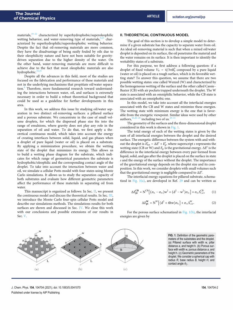
The geometry of the surfaces and the three-dimensional dropletconsidered in this work is shown in Fig. 1.
The total energy of each of the wetting states is given by thesum of all interfacial energies between the droplet and the desiredsurface. The energetic difference between the system with and with-out the droplet is Es
tot = ΔEs + Esg , where superscript s represents the
wetting state (CB or W) and Eg is the gravitational energy. ΔEs is thedifference in the interfacial energy between every pair formed fromliquid, solid, and gas after the droplet is placed on the surface in states and the energy of the surface without the droplet. The importanceof the gravitational energy depends on the droplet size and its com-position. In this work, we consider droplets with small volumes suchthat the gravitational energy is negligible compared to ΔEs.
The interfacial energy equations for pillared substrate, schema-tized in Fig. 1(a), are developed in Ref. 29 and can be written as
ΔECBpil = NCB[(σSL − σSG)w2 + (d2 −w2)σGL] + σGLSCB
CAP, (1)
ΔEWpil = NW[(d2 + 4hw)σSL] + σGLSW
CAP. (2)
For the porous surface schematized in Fig. 1(b), the interfacialenergies are given by
FIG. 1. Definition of the geometric para-meters of the substrates and the droplet.(a) Pillared surface with width w, pillardistance a, and height h. (b) Porous sur-face with width w, porous distance a, andheight h. (c) Geometric parameters of thedroplet. We consider a spherical cap withradius R, base radius B, height H, andcontact angle θC.
J. Chem. Phys. 154, 104704 (2021); doi: 10.1063/5.0041070 154, 104704-2
Published under license by AIP Publishing
The Journalof Chemical Physics ARTICLE scitation.org/journal/jcp
TABLE I. Surface tensions used in this work in units of mN/m. These values wereobtained for T = 25 ○C.
Water Solid Gas
Oil σWO = 53.5 σSO = 8.6 σGO = 27Water ⋯ σSW = 50.2 σGW = 70Solid ⋯ ⋯ σSG = 25
ΔECBpor = NCB[(d2 −w2)(σSL − σSG) + w2σGL] + σGLSCB
CAP, (3)
ΔEWpor = NW[(d2 −w2 + 4hw)(σSL − σSG) + w2σGL] + σGLSW
CAP. (4)
For Eqs. (1)–(4), d = w + a and σSG, σSL, and σGL are the surfacetensions for the solid–gas, solid–liquid, and liquid–gas interfaces,respectively. The subscript “L” accounts for a liquid phase and can beeither water or oil. Ns = πB2
d2 accounts for the number of pillars/poresunderneath the droplet and SCAP = 2πR2[1 − cos(θsc)] is the surfacearea of the spherical cap, where Bs = Rs sin(θsc) is the base radius andθsc is the contact angle of the droplet, as defined in Fig. 1(c).
In order to identify the favorable wetting state from the thermo-dynamic point of view for the pillared surface, we minimize Eqs. (1)and (2) and compare the global minimal energy for each state. Thisenergy minimization process goes as follows for the pillared sub-strate: first, we fix the surface parameters (a, h, and w) and thevolume V0 = 4
3πR30 of the droplet. Next, we solve a cubic equation
to obtain the radius of the droplet, Rs, for each state, CB or W. Then,
we vary the contact angle θsc ∈ [0, 180○) and use Eq. (1) to obtainΔECB and Eq. (2) for ΔEW. It allows us to build a curve of ener-gies as a function of θsc. We find the global minimum energy forCB, ΔECB
min, and for the W state, ΔEWmin. The thermodynamic wetting
state is the one with the smallest energy. In other words, for exam-ple, if ΔECB
min > ΔEWmin, then W is the thermodynamic wetting state.
This energy minimization process is explained with further detailsin Refs. 29 and 30 and we present an example in the supplementarymaterial. For the porous substrate, the process is analogous, but weuse Eqs. (3) and (4). Besides predicting the favorable wetting state,this approach also allows the determination of the geometric param-eters of the droplet associated with the most stable state, includingthe contact angle, θc.
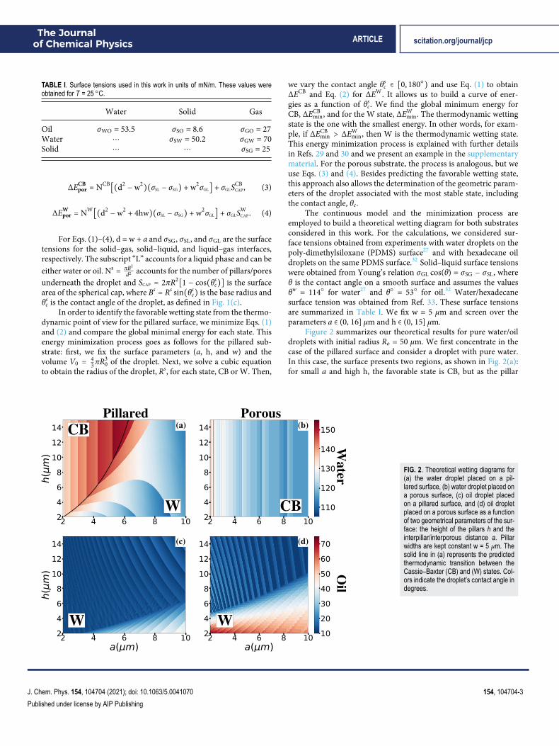
The continuous model and the minimization process areemployed to build a theoretical wetting diagram for both substratesconsidered in this work. For the calculations, we considered sur-face tensions obtained from experiments with water droplets on thepoly-dimethylsiloxane (PDMS) surface27 and with hexadecane oildroplets on the same PDMS surface.32 Solid–liquid surface tensionswere obtained from Young’s relation σGL cos(θ) = σSG − σSL, whereθ is the contact angle on a smooth surface and assumes the valuesθw = 114○ for water27 and θ○ = 53○ for oil.32 Water/hexadecanesurface tension was obtained from Ref. 33. These surface tensionsare summarized in Table I. We fix w = 5 μm and screen over theparameters a ∈ (0, 16] μm and h ∈ (0, 15] μm.
Figure 2 summarizes our theoretical results for pure water/oildroplets with initial radius Ro = 50 μm. We first concentrate in thecase of the pillared surface and consider a droplet with pure water.In this case, the surface presents two regions, as shown in Fig. 2(a):for small a and high h, the favorable state is CB, but as the pillar
FIG. 2. Theoretical wetting diagrams for(a) the water droplet placed on a pil-lared surface, (b) water droplet placed ona porous surface, (c) oil droplet placedon a pillared surface, and (d) oil dropletplaced on a porous surface as a functionof two geometrical parameters of the sur-face: the height of the pillars h and theinterpillar/interporous distance a. Pillarwidths are kept constant w = 5 μm. Thesolid line in (a) represents the predictedthermodynamic transition between theCassie–Baxter (CB) and (W) states. Col-ors indicate the droplet’s contact angle indegrees.
J. Chem. Phys. 154, 104704 (2021); doi: 10.1063/5.0041070 154, 104704-3
Published under license by AIP Publishing
The Journalof Chemical Physics ARTICLE scitation.org/journal/jcp
distance, a, increases, a transition to the W state is observed. Thistransition occurs for different values of a depending on the initialsize of the droplet, as shown in Ref. 29. Results for other values ofRo are shown in the supplementary material. When the droplet iscomposed of pure oil, W is the favorable state for any geometricparameter, as shown in Fig. 2(c).
The same process is applied for the porous substrate. When weconsider a droplet of pure water, no phase transition is observed andthe favorable wetting state is CB for any geometric parameter, asshown in Fig. 2(b). Nevertheless, lower contact angles were predictedwhen compared to the pillared surface, indicating that this surface isless hydrophobic. If a droplet of pure oil is taken into account, thethermodynamic state is W in the whole diagram [Fig. 2(d)]. In com-parison with the pillared surface, higher values of the contact anglewere observed for low values of porous height h.
The analysis presented here indicates that the porous surfacecould function as a good oil removing material regardless of thechoice of the surface geometrical parameters, but higher values ofporous height h would favor the separation due to the lower con-tact angles predicted for the oil droplets. For the pillared surface, weexpect a good oil/water separation in the region marked as CB inFig. 2(a).
However, this approach has the limitation of only consider-ing pure water or pure oil droplets, disregarding the effects ofwater–oil interaction. In order to overcome this limitation, weperform numerical simulations of the cellular Potts model takinginto account the promising interval of parameters obtained by thetheoretical analysis discussed in this section.
III. SIMULATIONS: FOUR-SPIN CELLULAR POTTSMODEL
Monte Carlo simulations (MC) of the cellular Potts model havebeen used to study wetting phenomena in textured surface34–36 butis also a useful tool to study cell migration on substrates.37–39 Thecoarse-grained approach used in these types of simulations (in oppo-sition to the explicit atom approach commonly used in moleculardynamic simulations) is a more consistent framework to treat meso-scopic systems and, therefore, more appropriate for comparisonwith experimental results.
Here, we expand the 3D cellular Potts model with three statesused to simulate the wetting properties of a pure liquid droplet29,30
to a four-spin model to be able to take into account a droplet com-posed of a mixture of two liquids: water and oil. Our model con-sists of a simple cubic lattice in which each state represents oneof the components: gas, water, oil, or solid. The Hamiltonian isgiven by
H = 12 ∑⟨i,j⟩
Esi ,sj(1 − δsi ,sj) + αw(∑iδsi ,1 − V
wT )
2
+αo(∑iδsi ,2 − V
oT)
2
+ g∑i(mihiδsi ,1 + mihiδsi ,2), (5)
where the spin si ∈ {0, 1, 2, 3} represents gas, water, oil, and solidstates, respectively.
The first term in Eq. (5) represents the energy related to thepresence of interfaces between sites of different types. The summa-tion ranges over pairs of neighbors, which comprise the 3D Mooreneighborhood in the simple cubic lattice (26 sites, excluding the cen-tral one), Esi ,sj is the interaction energies of sites si and sj of differentstates at interfaces, and δsi ,sj is the Kronecker delta.
In the second and third terms in Eq. (5), VwT and Vo
T arethe target water and oil volumes, respectively, the summations arethe water and oil volume, and the parameters αw and αo mimicthe liquids compressibility. Thus, these terms maintain the liquids’volumes and the desired composition of the droplet constant dur-ing the simulation. The last term is the gravitational energy, whereg = 10 m/s2 is the acceleration of gravity and mi is the mass of thesite. In both the volumetric and gravitational terms, only sites withliquid, si = 1 or si = 2, contribute.
In our simulations, the length scale is such that one lattice spac-ing corresponds to 1 μm and the surface tensions values (shown inTable I) are divided by 26, which is the number of neighbors thatcontributes to the first summation of our Hamiltonian. Therefore,the interfacial interaction energies Esi ,sj = Aσsisj , withA = 1 μm2 givenby E0,1 = 2.70 × 10⁻⁹ μJ, E0,2 = 1.04 × 10⁻⁹ μJ, E0,3 = 0.96 × 10⁻⁹ μJ,E1,2 = 2.06 × 10⁻⁹ μJ, E1,3 = 1.93 × 10⁻⁹ μJ, and E2,3 = 0.33 × 10⁻⁹ μJ.The mass existent in a unit cube is mw = 10−15 kg for water andmo = 0.77 × 10⁻¹⁵ kg for oil. We fix αw = αo = 0.01 × 10⁻⁹ μJ/(μm)6
(the choice of these values is justified in the supplementary material).The total run of a simulation is 5 × 10⁵ Monte Carlo steps
(MCSs), from which the last 2.5 × 10⁵ MCSs are used to measureobservables of interest. Each MCS is composed of VT = Vw + Vo
number of trial spin flips, where VT is the volume of the liquiddroplet, which is composed by a volume of oil Vo and water Vw.A spin flip is accepted with probability min{1, exp(−βΔH)}, whereβ = 1/T. In the cellular Potts model, T acts as noise to allow thephase space to be explored. In our simulations, a value of T = 9was used, which allows an acceptance rate of ∼15% while keepingboth water and oil in a liquid state (for further information, see thesupplementary material).
The initial wetting state is created using a hemisphere with ini-tial volume VT ≈ V0 = 4/3πR3
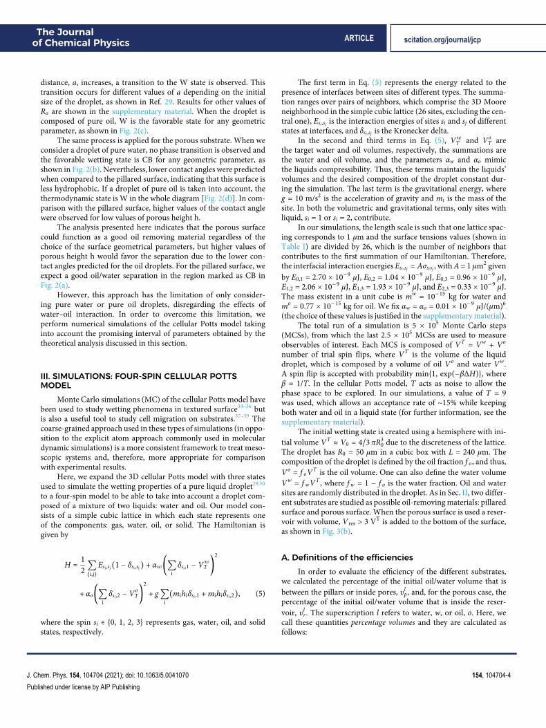
0 due to the discreteness of the lattice.The droplet has R0 = 50 μm in a cubic box with L = 240 μm. Thecomposition of the droplet is defined by the oil fraction f o, and thus,Vo = f oVT is the oil volume. One can also define the water volumeVw = f wVT , where f w = 1 − f o is the water fraction. Oil and watersites are randomly distributed in the droplet. As in Sec. II, two differ-ent substrates are studied as possible oil-removing materials: pillaredsurface and porous surface. When the porous surface is used a reser-voir with volume, Vres > 3 VT is added to the bottom of the surface,as shown in Fig. 3(b).
A. Definitions of the efficienciesIn order to evaluate the efficiency of the different substrates,
we calculated the percentage of the initial oil/water volume that isbetween the pillars or inside pores, υlp, and, for the porous case, thepercentage of the initial oil/water volume that is inside the reser-voir, υlr . The superscription l refers to water, w, or oil, o. Here, wecall these quantities percentage volumes and they are calculated asfollows:
J. Chem. Phys. 154, 104704 (2021); doi: 10.1063/5.0041070 154, 104704-4
Published under license by AIP Publishing
The Journalof Chemical Physics ARTICLE scitation.org/journal/jcp
FIG. 3. Visual schematic of the initialsetup of the simulations for (a) the pil-lared surface and (b) the porous surface.Legend shows the label of the spins thatrepresent each state.
υlp = V lp/V l, (6)
υlr = V lr/V l, (7)
where V lp is the volume of the liquid (water or oil) between the pillar
or inside the pores and V lr is the volume of the liquid inside the reser-
voir. These percentage volumes allow us to define a liquid absorptioncapacity for the pillared and porous surface that measures how muchof the initial liquid volume was absorbed by the substrate,
εlpil = υlp, (8)
εlpor = υlp + υlr . (9)
The ideal substrate for oil and water separation, in our case,is such that all the initial water volume remains above the surfaceand all the initial oil volume is adsorbed by the substrate. We thenintroduce a quantity to measure a separation efficiency that takesinto account the capacity of a substrate to simultaneously retain thewater and absorb the oil,
ξS =εoS + (1 − εwS )
2, (10)
where the index S refers to the pillared or porous surface.We also measure in our simulations two efficiencies that are
commonly used in experiments. The first one measures the amountof water that is not absorbed by the substrate.40,41 In our case, thisefficiency is calculated as follows:
ξapil = 1 − υwp , (11)
ξapor = 1 − υwp − υwr . (12)
The second one measures the oil rejection coefficient given byR = (1 − Cp/Co), where Co is the initial concentration of oil, which,
in our case, is f o, and Cp is the concentration of oil in the remainingwater above the surface.42,43 In our simulation, this efficiency iscalculated as follows:
ξrpil = 1 − [Vo − Vo
p
VT − [Vwp + Vo
p]1fo], (13)
ξrpor = 1 − [Vo − (Vo
p + Vor )
VT − [(Vwp + Vw
r ) + (Vop + Vo
r )]1fo]. (14)
IV. RESULTS AND DISCUSSIONIn this section, we analyze the simulation results for pillared
surfaces [Fig. 1(a)] and porous surfaces, exemplified in Fig. 1(b). Wecompare these results with the theoretical predictions presented inSec. II and discuss the efficiency of these two types of surfaces inseparating water from oil.
A. Pillared surfaceThe theoretical results summarized in Fig. 2 show that, if a
pure water droplet is placed on a pillared surface, it presents a CBand W regions depending on the substrate’s geometrical parame-ters. As previously explained, these wetting states are associated withhydrophilic and hydrophobic behaviors, respectively. For any geo-metric parameter, if a pure oil droplet is deposited on the substrate,its favorable state is W, indicating that these substrates are oleophilic.Then, we expect that pillared surfaces could work as an oil removingmaterial in the region where a pure water droplet is in a CB state. Ifthis is the case, these substrates would act as “sponges,” absorbing oiland leaving water above the pillars.
With that in mind, here, we study surfaces with fixed pillarheight h = 10 μm and pillar width w = 5 μm and several values ofpillar distance a. In the supplementary material, we also show theanalyses for the case with h = 5 μm, which presents very similarresults. Figure 4 shows the interpillar percentage volume, υlp, as afunction of the pillar distance a for f o = 0.10 [Fig. 4(a)] and f o = 0.90
J. Chem. Phys. 154, 104704 (2021); doi: 10.1063/5.0041070 154, 104704-5
Published under license by AIP Publishing
The Journalof Chemical Physics ARTICLE scitation.org/journal/jcp
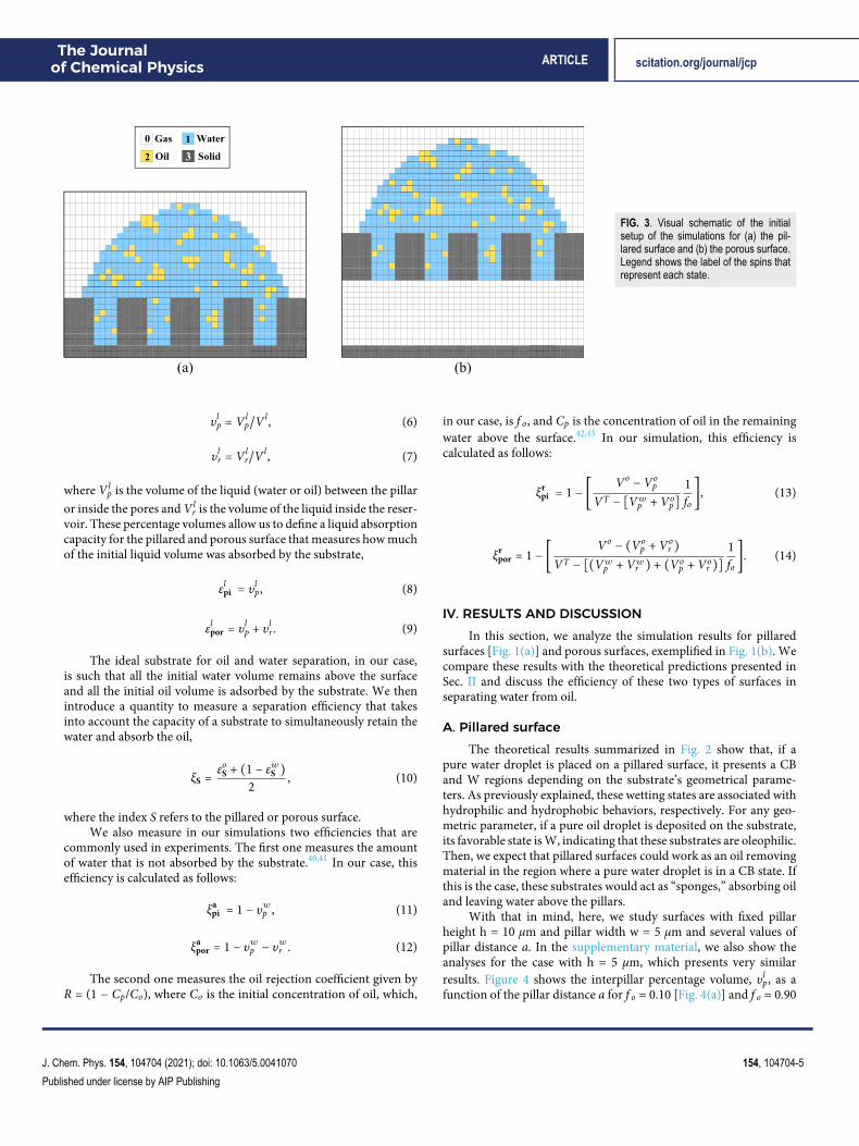
FIG. 4. Results for pillared substrates for several geometric parameters. Top: interpillar volume of water, υwp , and oil, υop, as a function of the pillar distance a for (a)f o = 0.10 and (b) f o = 0.90. Bottom: [(c)–(f)] cross sections of the final droplet configuration of Monte Carlo simulations for a = 2 μm and a = 14 μm for each correspondingf o. To build this figure, a mixed droplet with oil fraction given by f o (value specified above the figures) and total volume given by VT = 4/3πR3
0 with R0 = 50 μm is simulatedon a substrate with w = 5 μm, h = 10 μm, and varying pillar distance a. Blue represents water and orange represents oil. Dotted lines represent the CB-W transition predictedby the theoretical model and the dashed line represents the maximum volume available between pillars Vmax normalized by the total oil volume, Vo.
[Fig. 4(b)] and cross sections of the droplet configuration in the finalstate of the Monte Carlo simulations corresponding to two differentpillar distances, a = 2 μm and a = 14 μm, for each f o. The verticalgray dotted lines shown in Figs. 4(a) and 4(b) indicate the waterCB-W transition predicted by the theoretical continuous modeldescribed above for the corresponding water volume. We empha-size that the value of the interpillar distance, a, for which the CB-Wtransition occurs varies with the droplet initial volume as mentionedpreviously and is discussed in more detail in the supplementarymaterial.
The available volume to absorb oil is the maximum volumebetween pillars, given by Vmax = ( Ld)
2(d2 −w2)h. We normalize thisvolume by the total oil volume present in the droplet Vo, Vmax/Vo,and show that this quantity in Fig. 4(b) is represented by the graydashed line. This curve does not appear for the smaller oil fractionf o because Vmax ≫ Vo for all values of a.
For both cases, we observe that for low values of interpillardistance a water does not penetrates the pore, υwp ≈ 0 [Figs. 4(a)and 4(b)], which is consistent with a CB wetting state. For highervalues of the interpillar distance a, we observed an increase in υwp ,which roughly coincides with the theoretical prediction from CB toW states indicated by the vertical gray dotted line in Figs. 4(a) and4(b). This is visually confirmed by the cross sections of the final con-figurations shown in Figs. 4(c) and 4(d) where the water is in the CBstate for a = 2 μm and in the W state for a = 14 μm. We have checkedthat it also happens for f o = 0.9 [Figs. 4(e) and 4(f)], but it is not pos-sible to visualize because the oil sites dominate the image and do notallow us to properly see the water behavior.
Although we obtain good agreement with the theoretical resultsfor the water behavior, we note that, when considering the mix-ture, the phase transition occurs for higher values of the interpillar
distance a. This discrepancy is expected because the wetting dia-gram, obtained by the theoretical continuous model, is built for apure water droplet or pure oil droplet, while in the simulations, thereis a composition of both liquids.
We now discuss the oil behavior. Theoretical calculations showthat a pure oil droplet does not undergo any wetting state transi-tion, remaining in the W state for all values of interpillar distancea. This is qualitatively confirmed by simulations, as shown by theoil penetration in Figs. 4(a) and 4(b). For f o = 0.10 [Fig. 4(a)] andlow values of the interpillar distance, a υop indicates that 88% of theinitial oil volume penetrates the substrate. As a is increased, the per-centage decreases and a plateau is observed at υop ≈ 0.73. For thecase with f o = 0.9, we observe an increase in υop with the increasein a and a plateau is reached at υop ≈ 0.93. This change in the oilabsorption behavior is due to the substrate available volume, Vmax.For lower values of the interpillar distance, a, the pillared surface hasspace to accommodate roughly 60% of the initial oil volume, as indi-cated by the gray dashed line, resulting in a reduced oil absorptioncapacity and the saturation of the substrate. Increasing the interpil-lar distance a also increases the available volume, Vmax, and a betteroil absorption capacity is observed.
Despite the high percentage of the oil absorbed by the sur-face, we note that from 7% to 27% of the initial oil remains abovethe surface. We have checked that all the remaining oil is at theinterface of the droplet, which creates a water–oil–gas interface. Wenote that reminiscent oil in the remaining water was also observedexperimentally.44,45
To understand this feature in our simulations, we analyzed theterms of Eq. (5) related to the energy for creating interfaces and eval-uated the necessary conditions for the appearance of a spin of type“oil” on the interface between the water and the gas. The calculations
J. Chem. Phys. 154, 104704 (2021); doi: 10.1063/5.0041070 154, 104704-6
Published under license by AIP Publishing
The Journalof Chemical Physics ARTICLE scitation.org/journal/jcp
and more detailed arguments are discussed in the supplementarymaterial. This analysis led to two main conclusions: (i) the pres-ence of an oil site on the interface of the droplet is favored whenthere are other oil sites surrounding it, suggesting that in the exper-iment, the oil would form a film on the interface of the droplet and(ii) the formation of the oil film prevents a water–gas interface thatis energetically unfavorable due to the σGW–σWO relation due to thefact that σGW > σWO. This suggests that changing the surroundinggas in order to change the surface tensions relation may benefit theseparation of oil and water.
To conclude this section, we discuss the efficiency of this typeof substrate using three different definitions introduced in Sec. III.We measure ξapil, defined in Eq. (11), which measures the amount ofwater that is not absorbed by the surface, and ξrpil, defined in Eq. (13),which measures the capacity of the surface to exclude oil from thewater that remains above the surface. We compare these quanti-ties with the proposed separation efficiency given by Eq. (10), whichtakes into account both the capacity of maintaining water above thesubstrate and the capacity of absorbing oil.
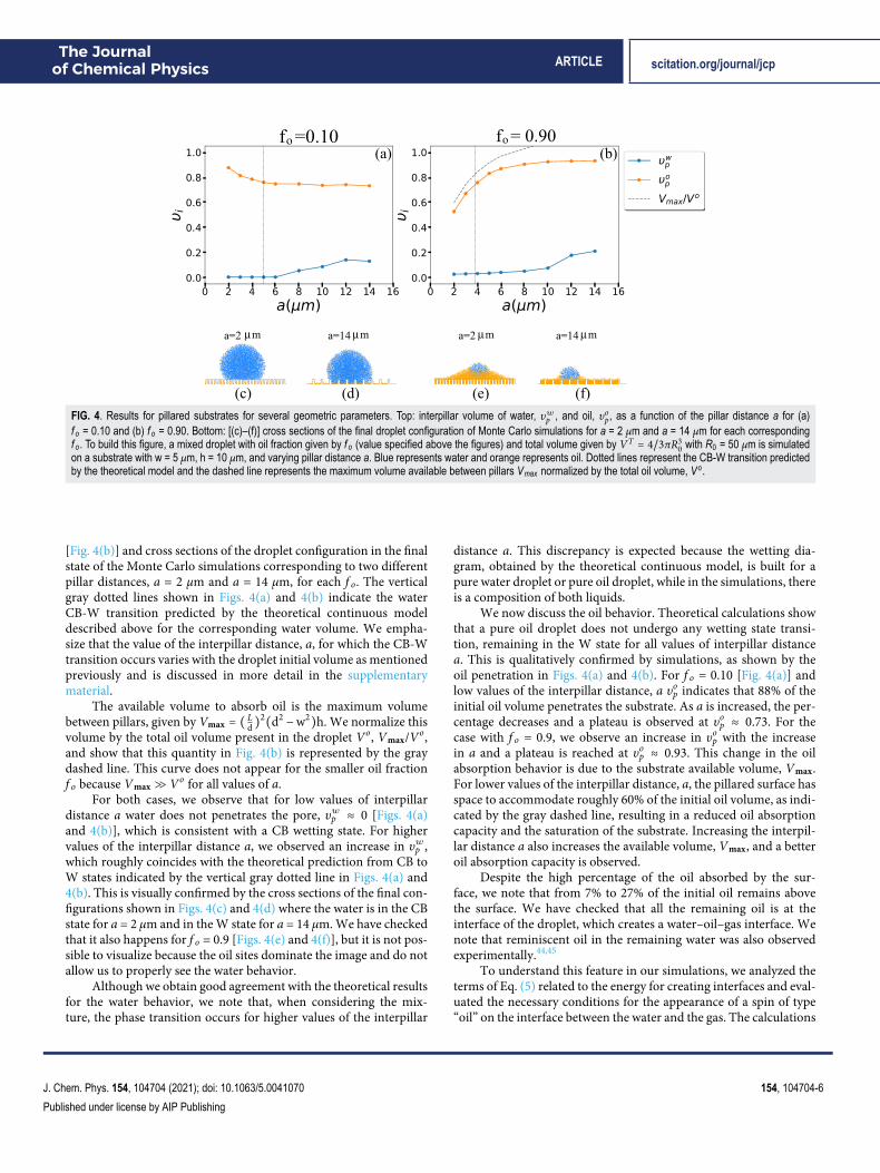
Figure 5 summarizes our results for all geometries consideredhere. For both values of f o, ξapil follows the behavior of water: it showshigh efficiency when the water is in the CB state and decays when thetransition to W occurs. The ξrpil, on the other hand, follows roughlythe behavior of the oil where the efficiency is high for surfaces wherethe oil percentage volume υop is also high.
These definitions of efficiency have the disadvantage of onlyconsidering one aspect of the separation process, which is theabsorption of the oil or the amount of water remaining above thesurface. For instance, let us consider the case of f o = 0.90 anda = 2 μm. ξapil indicates an efficiency of this substrate of ∼100%despite the fact that about 50% of the oil remains above the sur-face, as shown in Fig. 4(e). In other words, ξapil is high becausethere is no absorption of water by the substrate, but it is misleadingbecause if the oil remains above the surface too, then the separationof water and oil is not as good as its high value may suggest at thefirst glance. On the other hand, ξrpil has a low value despite the factthat almost the whole amount the initial water remains above thesubstrate.
The definition of efficiency ξpil introduced in this work foroil removing materials takes into account both the water retentionabove the substrate and the oil absorption, which are the mecha-nisms that contribute to the water/oil separation. Thus, consideringthe same case of f o = 0.90 and a = 2 μm discussed above, ξpil is lower
than ξapil because it considers the reminiscent oil above the surfaceand ξpil is greater than ξrpil because it considers the quantity andpurity of the absorbed oil.
Despite the good efficiency observed for some these pillaredsurface, they have the limitation of only being able to absorb a cer-tain volume of oil, Vmax. In Sec. IV B, we evaluate the performanceof a surface that, in principle, does not have this problem.
B. Porous surfaceIn this section, we consider a porous substrate where the oil
can be drained into a reservoir. Here, we explore this surface for thesame oil fractions f o and similar geometrical parameters consideredfor the pillared surface: w = 5 μm, h = 10 μm, and several values ofporous distance a. According to the theoretical predictions, for purewater or pure oil, there is no wetting transition: the porous surface ishydrophobic and oleophilic for all values of geometric parameters,as summarized in Figs. 2(b) and 2(d).
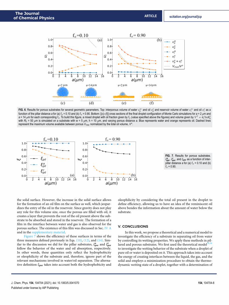
Figure 6 shows the interporous percentage volume υlp and thereservoir percentage volume υlr as a function of porous distance afor two oil fractions, f o = 0.10 and 0.90. For this type of surface, thevolume normalization is such that Vl
p + Vlr + Vl
a = V l, where Vla
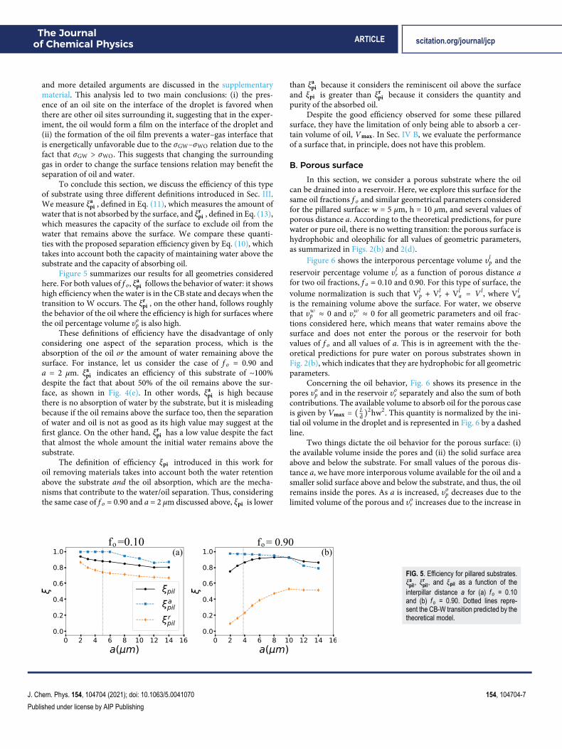
is the remaining volume above the surface. For water, we observethat υwp ≈ 0 and υwr ≈ 0 for all geometric parameters and oil frac-tions considered here, which means that water remains above thesurface and does not enter the porous or the reservoir for bothvalues of f o and all values of a. This is in agreement with the the-oretical predictions for pure water on porous substrates shown inFig. 2(b), which indicates that they are hydrophobic for all geometricparameters.
Concerning the oil behavior, Fig. 6 shows its presence in thepores υop and in the reservoir υor separately and also the sum of bothcontributions. The available volume to absorb oil for the porous caseis given by Vmax = ( Ld)
2hw2. This quantity is normalized by the ini-tial oil volume in the droplet and is represented in Fig. 6 by a dashedline.
Two things dictate the oil behavior for the porous surface: (i)the available volume inside the pores and (ii) the solid surface areaabove and below the substrate. For small values of the porous dis-tance a, we have more interporous volume available for the oil and asmaller solid surface above and below the substrate, and thus, the oilremains inside the pores. As a is increased, υop decreases due to thelimited volume of the porous and υor increases due to the increase in
FIG. 5. Efficiency for pillared substrates.ξa
pil, ξrpil, and ξpil as a function of the
interpillar distance a for (a) f o = 0.10and (b) f o = 0.90. Dotted lines repre-sent the CB-W transition predicted by thetheoretical model.
J. Chem. Phys. 154, 104704 (2021); doi: 10.1063/5.0041070 154, 104704-7
Published under license by AIP Publishing
The Journalof Chemical Physics ARTICLE scitation.org/journal/jcp
FIG. 6. Results for porous substrates for several geometric parameters. Top: interporous volume of water υwp and oil υop and reservoir volume of water υwr and oil υor as afunction of the pillar distance a for (a) f o = 0.10 and (b) f o = 0.90. Bottom: [(c)–(f)] cross sections of the final droplet configuration of Monte Carlo simulations for a = 2 μm anda = 14 μm for each corresponding f o. To build this figure, a mixed droplet with oil fraction given by f o (value specified above the figures) and volume given by VT = 4/3πR3
0with R0 = 50 μm is simulated on a substrate with w = 5 μm, h = 10 μm, and varying porous distance a. Blue represents water and orange represents oil. Dashed linesrepresent the maximum volume available between porous Vmax normalized by the total oil volume, Vo.
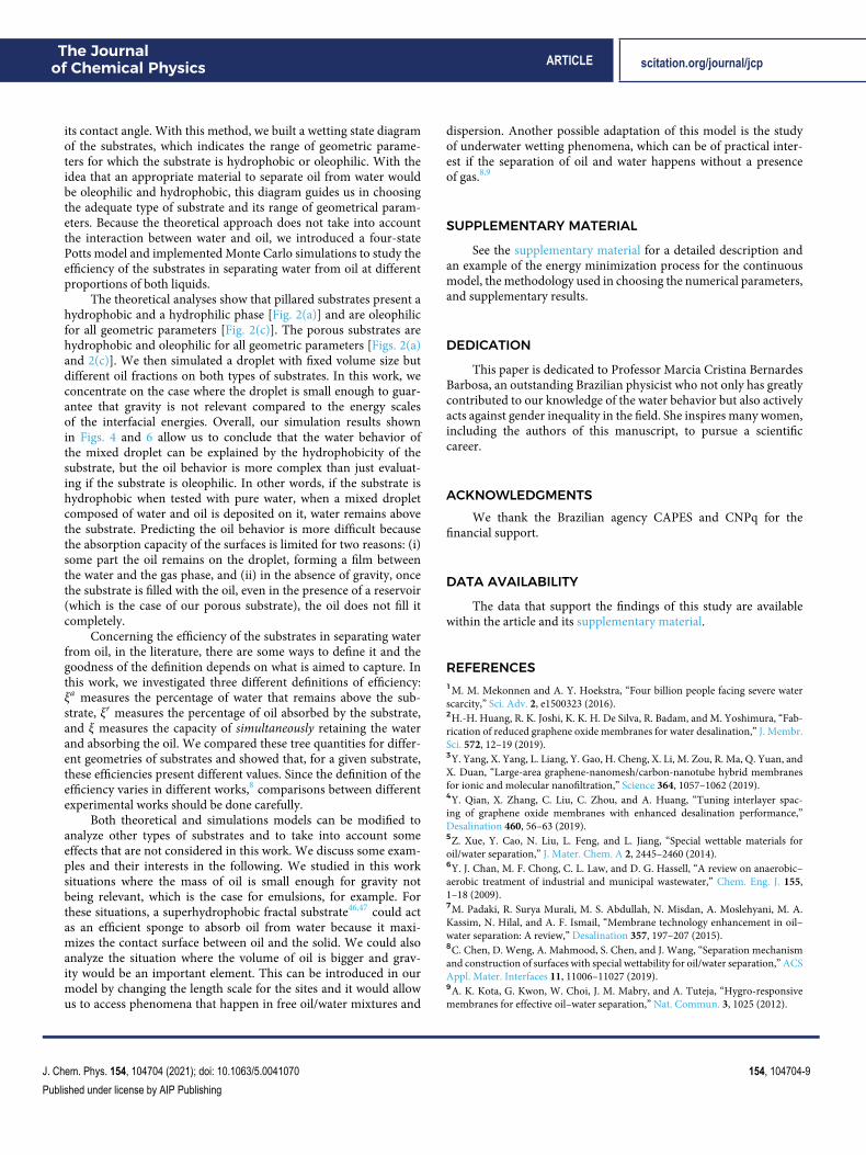
FIG. 7. Results for porous substrates.ξa
por, ξrpor, and ξpor as a function of inter-
pillar distance a for (a) f o = 0.10 and (b)f o = 0.90.
the solid surface. However, the increase in the solid surface allowsfor the formation of an oil film on the surface as well, which jeopar-dizes the entry of the oil in the reservoir. Since gravity does not playany role for this volume size, once the porous are filled with oil, itcreates a layer that prevents the rest of the oil present above the sub-strate to be absorbed and stored in the reservoir. The formation of afilm in the interface between water and gas is also observed for theporous surface. The existence of this film was discussed in Sec. IV Aand in the supplementary material.
Figure 7 shows the efficiency of these surfaces in terms of thethree measures defined previously in Eqs. (10), (12), and (14). Sim-ilar to the discussion we did for the pillar substrates, ξapor and ξrporfollow the behavior of the water and oil absorption, respectively.In other words, these quantities only reflect the hydrophobicityor oleophilicity of the substrate and, therefore, ignore part of therelevant mechanisms involved in water/oil separation. The alterna-tive definition ξpor takes into account both the hydrophobicity and
oleophilicity by considering the total oil present in the droplet todefine efficiency, allowing us to have an idea of the reminiscent oilabove besides the information about the amount of water below thesubstrate.
V. CONCLUSIONSIn this work, we propose a theoretical and a numerical model to
investigate the efficiency of a substrate in separating oil from waterby controlling its wetting properties. We apply these methods in pil-lared and porous substrates. We first used the theoretical model29,30
to investigate the wetting behavior of the substrate when a droplet ofpure oil or water is deposited on it. This approach takes into accountthe energy of creating interfaces between the liquid, the gas, and thesolid and employs a minimization procedure to obtain the thermo-dynamic wetting state of a droplet, together with a determination of
J. Chem. Phys. 154, 104704 (2021); doi: 10.1063/5.0041070 154, 104704-8
Published under license by AIP Publishing
The Journalof Chemical Physics ARTICLE scitation.org/journal/jcp
its contact angle. With this method, we built a wetting state diagramof the substrates, which indicates the range of geometric parame-ters for which the substrate is hydrophobic or oleophilic. With theidea that an appropriate material to separate oil from water wouldbe oleophilic and hydrophobic, this diagram guides us in choosingthe adequate type of substrate and its range of geometrical param-eters. Because the theoretical approach does not take into accountthe interaction between water and oil, we introduced a four-statePotts model and implemented Monte Carlo simulations to study theefficiency of the substrates in separating water from oil at differentproportions of both liquids.
The theoretical analyses show that pillared substrates present ahydrophobic and a hydrophilic phase [Fig. 2(a)] and are oleophilicfor all geometric parameters [Fig. 2(c)]. The porous substrates arehydrophobic and oleophilic for all geometric parameters [Figs. 2(a)and 2(c)]. We then simulated a droplet with fixed volume size butdifferent oil fractions on both types of substrates. In this work, weconcentrate on the case where the droplet is small enough to guar-antee that gravity is not relevant compared to the energy scalesof the interfacial energies. Overall, our simulation results shownin Figs. 4 and 6 allow us to conclude that the water behavior ofthe mixed droplet can be explained by the hydrophobicity of thesubstrate, but the oil behavior is more complex than just evaluat-ing if the substrate is oleophilic. In other words, if the substrate ishydrophobic when tested with pure water, when a mixed dropletcomposed of water and oil is deposited on it, water remains abovethe substrate. Predicting the oil behavior is more difficult becausethe absorption capacity of the surfaces is limited for two reasons: (i)some part the oil remains on the droplet, forming a film betweenthe water and the gas phase, and (ii) in the absence of gravity, oncethe substrate is filled with the oil, even in the presence of a reservoir(which is the case of our porous substrate), the oil does not fill itcompletely.
Concerning the efficiency of the substrates in separating waterfrom oil, in the literature, there are some ways to define it and thegoodness of the definition depends on what is aimed to capture. Inthis work, we investigated three different definitions of efficiency:ξa measures the percentage of water that remains above the sub-strate, ξr measures the percentage of oil absorbed by the substrate,and ξ measures the capacity of simultaneously retaining the waterand absorbing the oil. We compared these tree quantities for differ-ent geometries of substrates and showed that, for a given substrate,these efficiencies present different values. Since the definition of theefficiency varies in different works,8 comparisons between differentexperimental works should be done carefully.
Both theoretical and simulations models can be modified toanalyze other types of substrates and to take into account someeffects that are not considered in this work. We discuss some exam-ples and their interests in the following. We studied in this worksituations where the mass of oil is small enough for gravity notbeing relevant, which is the case for emulsions, for example. Forthese situations, a superhydrophobic fractal substrate46,47 could actas an efficient sponge to absorb oil from water because it maxi-mizes the contact surface between oil and the solid. We could alsoanalyze the situation where the volume of oil is bigger and grav-ity would be an important element. This can be introduced in ourmodel by changing the length scale for the sites and it would allowus to access phenomena that happen in free oil/water mixtures and
dispersion. Another possible adaptation of this model is the studyof underwater wetting phenomena, which can be of practical inter-est if the separation of oil and water happens without a presenceof gas.8,9
SUPPLEMENTARY MATERIAL
See the supplementary material for a detailed description andan example of the energy minimization process for the continuousmodel, the methodology used in choosing the numerical parameters,and supplementary results.
DEDICATION
This paper is dedicated to Professor Marcia Cristina BernardesBarbosa, an outstanding Brazilian physicist who not only has greatlycontributed to our knowledge of the water behavior but also activelyacts against gender inequality in the field. She inspires many women,including the authors of this manuscript, to pursue a scientificcareer.
ACKNOWLEDGMENTSWe thank the Brazilian agency CAPES and CNPq for the
financial support.
DATA AVAILABILITY
The data that support the findings of this study are availablewithin the article and its supplementary material.
REFERENCES1M. M. Mekonnen and A. Y. Hoekstra, “Four billion people facing severe waterscarcity,” Sci. Adv. 2, e1500323 (2016).2H.-H. Huang, R. K. Joshi, K. K. H. De Silva, R. Badam, and M. Yoshimura, “Fab-rication of reduced graphene oxide membranes for water desalination,” J. Membr.Sci. 572, 12–19 (2019).3Y. Yang, X. Yang, L. Liang, Y. Gao, H. Cheng, X. Li, M. Zou, R. Ma, Q. Yuan, andX. Duan, “Large-area graphene-nanomesh/carbon-nanotube hybrid membranesfor ionic and molecular nanofiltration,” Science 364, 1057–1062 (2019).4Y. Qian, X. Zhang, C. Liu, C. Zhou, and A. Huang, “Tuning interlayer spac-ing of graphene oxide membranes with enhanced desalination performance,”Desalination 460, 56–63 (2019).5Z. Xue, Y. Cao, N. Liu, L. Feng, and L. Jiang, “Special wettable materials foroil/water separation,” J. Mater. Chem. A 2, 2445–2460 (2014).6Y. J. Chan, M. F. Chong, C. L. Law, and D. G. Hassell, “A review on anaerobic–aerobic treatment of industrial and municipal wastewater,” Chem. Eng. J. 155,1–18 (2009).7M. Padaki, R. Surya Murali, M. S. Abdullah, N. Misdan, A. Moslehyani, M. A.Kassim, N. Hilal, and A. F. Ismail, “Membrane technology enhancement in oil–water separation: A review,” Desalination 357, 197–207 (2015).8C. Chen, D. Weng, A. Mahmood, S. Chen, and J. Wang, “Separation mechanismand construction of surfaces with special wettability for oil/water separation,” ACSAppl. Mater. Interfaces 11, 11006–11027 (2019).9A. K. Kota, G. Kwon, W. Choi, J. M. Mabry, and A. Tuteja, “Hygro-responsivemembranes for effective oil–water separation,” Nat. Commun. 3, 1025 (2012).
J. Chem. Phys. 154, 104704 (2021); doi: 10.1063/5.0041070 154, 104704-9
Published under license by AIP Publishing
The Journalof Chemical Physics ARTICLE scitation.org/journal/jcp
10M. Cheryan and N. Rajagopalan, “Membrane processing of oily streams.Wastewater treatment and waste reduction,” J. Membr. Sci. 151, 13–28 (1998).11J. A. Zeevalkink and J. J. Brunsmann, “Oil removal from water in parallel plategravity-type separators,” Water Res. 17, 365–373 (1983).12D. Sun, X. Duan, W. Li, and D. Zhou, “Demulsification of water-in-oil emulsionby using porous glass membrane,” J. Membr. Sci. 146, 65–72 (1998).13A. Cambiella, J. M. Benito, C. Pazos, and J. Coca, “Centrifugal separation effi-ciency in the treatment of waste emulsified oils,” Chem. Eng. Res. Des. 84, 69–76(2006).14M. Comba and K. Kaiser, “Suspended particulate concentrations in the St.Lawrence river (1985–1987) determined by centrifugation and filtration,” Sci.Total Environ. 97-98, 191–206 (1990).15T. Strøm-Kristiansen, A. Lewis, P. S. Daling, and A. B. Nordvik, “Heat andchemical treatment of mechanically recovered w/o emulsions,” Spill Sci. Technol.Bull. 2, 133–141 (1995).16D. Quéré, “Wetting and roughness,” Annu. Rev. Mater. Res. 38, 71–99 (2008).17R. N. Wenzel, “Resistance of solid surfaces to wetting by water,” Indust. Eng.Chem. 28, 988–994 (1936).18R. N. Wenzel, “Surface roughness and contact angle,” J. Phys. Chem. 53,1466–1467 (1949).19L. Feng, Z. Zhang, Z. Mai, Y. Ma, B. Liu, L. Jiang, and D. Zhu, “A super-hydrophobic and super-oleophilic coating mesh film for the separation of oil andwater,” Angew. Chem., Int. Ed. 43, 2012–2014 (2004).20X. Gui, J. Wei, K. Wang, A. Cao, H. Zhu, Y. Jia, Q. Shu, and D. Wu, “Carbonnanotube sponges,” Adv. Mater. 22, 617–621 (2010).21B. Cortese, D. Caschera, F. Federici, G. M. Ingo, and G. Gigli, “Superhy-drophobic fabrics for oil–water separation through a diamond like carbon (DLC)coating,” J. Mater. Chem. A 2, 6781–6789 (2014).22Y. Zhan, S. He, J. Hu, S. Zhao, G. Zeng, M. Zhou, G. Zhang, andA. Sengupta, “Robust super-hydrophobic/super-oleophilic sandwich-like UIO-66-F4@rGO composites for efficient and multitasking oil/water separation appli-cations,” J. Hazard. Mater. 388, 121752 (2020).23J. Yang, Z. Zhang, X. Xu, X. Zhu, X. Men, and X. Zhou, “Superhydrophilic–superoleophobic coatings,” J. Mater. Chem. 22, 2834–2837 (2012).24A. Tuteja, W. Choi, M. Ma, J. M. Mabry, S. A. Mazzella, G. C. Rutledge, G. H.McKinley, and R. E. Cohen, “Designing superoleophobic surfaces,” Science 318,1618–1622 (2007).25A. Ahuja, J. A. Taylor, V. Lifton, A. A. Sidorenko, T. R. Salamon, E. J. Lobaton,P. Kolodner, and T. N. Krupenkin, “Nanonails: A simple geometrical approach toelectrically tunable superlyophobic surfaces,” Langmuir 24, 9–14 (2008).26M. Sbragaglia, A. Peters, C. Pirat, B. Borkent, R. Lammertink, M. Wessling, andD. Lohse, “Spontaneous breakdown of superhydrophobicity,” Phys. Rev. Lett. 99,156001 (2007).27P. Tsai, R. Lammertink, M. Wessling, and D. Lohse, “Evaporation-triggeredwetting transition for water droplets upon hydrophobic microstructures,” Phys.Rev. Lett. 104, 116102 (2010).28A. Shahraz, A. Borhan, and K. A. Fichthorn, “A theory for the morphologi-cal dependence of wetting on a physically patterned solid surface,” Langmuir 28,14227–14237 (2012).29H. C. M. Fernandes, M. H. Vainstein, and C. Brito, “Modeling of dropletevaporation on superhydrophobic surfaces,” Langmuir 31, 7652–7659 (2015).30M. Silvestrini and C. Brito, “Wettability of reentrant surfaces: A global energyapproach,” Langmuir 33, 12535–12545 (2017).
31D. Lazzari and C. Brito, “Geometric and chemical nonuniformity may inducethe stability of more than one wetting state in the same hydrophobic surface,”Phys. Rev. E 99, 032801 (2019).32S. Martin and B. Bhushan, “Transparent, wear-resistant, superhydrophobic andsuperoleophobic poly(dimethylsiloxane) (PDMS) surfaces,” J. Colloid InterfaceSci. 488, 118–126 (2017).33D. Wu and V. Hornof, “Dynamic interfacial tension in hexadecane/watersystems containing ready-made and in-situ-formed surfactants,” Chem. Eng.Commun. 172, 85–106 (1999).34D. M. Lopes, S. M. M. Ramos, L. R. de Oliveira, and J. C. M. Mombach, “Cassie-Baxter to Wenzel state wetting transition: A 2D numerical simulation,” RSC Adv.3, 24530–24534 (2013).35L. R. de Oliveira, D. M. Lopes, S. M. M. Ramos, and J. C. M. Mombach,“Two-dimensional modeling of the superhydrophobic behavior of a liquid dropletsliding down a ramp of pillars,” Soft Matter 7, 3763–3765 (2011).36V. Mortazavi, R. M. D’Souza, and M. Nosonovsky, “Study of contact angle hys-teresis using the cellular Potts model,” Phys. Chem. Chem. Phys. 15, 2749–2756(2013).37F. Graner and J. A. Glazier, “Simulation of biological cell sorting using a two-dimensional extended Potts model,” Phys. Rev. Lett. 69, 2013–2017 (1992).38I. Fortuna, G. C. Perrone, M. S. Krug, E. Susin, J. M. Belmonte, G. L. Thomas,J. A. Glazier, and R. M. de Almeida, “CompuCell3D simulations reproducemesenchymal cell migration on flat substrates,” Biophys. J. 118, 2801 (2020).39R. Magno, V. A. Grieneisen, and A. F. Marée, “The biophysical nature of cells:Potential cell behaviours revealed by analytical and computational studies of cellsurface mechanics,” BMC Biophys. 8, 8 (2015).40J. Gu, P. Xiao, J. Chen, F. Liu, Y. Huang, G. Li, J. Zhang, and T. Chen, “Robustpreparation of superhydrophobic polymer/carbon nanotube hybrid membranesfor highly effective removal of oils and separation of water-in-oil emulsions,”J. Mater. Chem. A 2, 15268–15272 (2014).41A. K. Singh and J. K. Singh, “Fabrication of zirconia based durablesuperhydrophobic–superoleophilic fabrics using non fluorinated materials foroil–water separation and water purification,” RSC Adv. 6, 103632–103640(2016).42Z. Wang, C. Xiao, Z. Wu, Y. Wang, X. Du, W. Kong, D. Pan, G. Guan, andX. Hao, “A novel 3D porous modified material with cage-like structure: Fabri-cation and its demulsification effect for efficient oil/water separation,” J. Mater.Chem. A 5, 5895–5904 (2017).43M. Su, Y. Liu, S. Li, Z. Fang, B. He, Y. Zhang, Y. Li, and P. He, “A rubber-like,underwater superoleophobic hydrogel for efficient oil/water separation,” Chem.Eng. J. 361, 364–372 (2019).44M. A. Gondal, M. S. Sadullah, M. A. Dastageer, G. H. McKinley, D.Panchanathan, and K. K. Varanasi, “Study of factors governing oil–waterseparation process using TiO2 films prepared by spray deposition of nanoparticledispersions,” ACS Appl. Mater. Interfaces 6, 13422–13429 (2014).45Y. Liu, K. Zhang, W. Yao, C. Zhang, Z. Han, and L. Ren, “A facile electrodepo-sition process for the fabrication of superhydrophobic and superoleophilic coppermesh for efficient oil–water separation,” Ind. Eng. Chem. Res. 55, 2704–2712(2016).46T. Onda, S. Shibuichi, N. Satoh, and K. Tsujii, “Super-water-repellent fractalsurfaces,” Langmuir 12, 2125–2127 (1996).47A.-L. Barabási and H. E. Stanley, Fractal Concepts in Surface Growth(Cambridge University Press, 1995).
J. Chem. Phys. 154, 104704 (2021); doi: 10.1063/5.0041070 154, 104704-10
Published under license by AIP Publishing