Embed Size (px)
Citation preview
This article was downloaded by: [The Aga Khan University]On: 10 October 2014, At: 23:36Publisher: Taylor & FrancisInforma Ltd Registered in England and Wales Registered Number: 1072954 Registeredoffice: Mortimer House, 37-41 Mortimer Street, London W1T 3JH, UK
Numerical Heat Transfer, Part A:Applications: An International Journal ofComputation and MethodologyPublication details, including instructions for authors andsubscription information:http://www.tandfonline.com/loi/unht20
Modeling of Valveless MicropumpsYeng-Yung Tsui a & Shin-En Wu aa Department of Mechanical Engineering , National Chiao TungUniversity , Taiwan, Republic of ChinaPublished online: 10 Dec 2009.
To cite this article: Yeng-Yung Tsui & Shin-En Wu (2009) Modeling of Valveless Micropumps, NumericalHeat Transfer, Part A: Applications: An International Journal of Computation and Methodology, 56:9,727-745, DOI: 10.1080/10407780903466089
To link to this article: http://dx.doi.org/10.1080/10407780903466089
PLEASE SCROLL DOWN FOR ARTICLE
Taylor & Francis makes every effort to ensure the accuracy of all the information (the“Content”) contained in the publications on our platform. However, Taylor & Francis,our agents, and our licensors make no representations or warranties whatsoever as tothe accuracy, completeness, or suitability for any purpose of the Content. Any opinionsand views expressed in this publication are the opinions and views of the authors,and are not the views of or endorsed by Taylor & Francis. The accuracy of the Contentshould not be relied upon and should be independently verified with primary sourcesof information. Taylor and Francis shall not be liable for any losses, actions, claims,proceedings, demands, costs, expenses, damages, and other liabilities whatsoever orhowsoever caused arising directly or indirectly in connection with, in relation to or arisingout of the use of the Content.
This article may be used for research, teaching, and private study purposes. Anysubstantial or systematic reproduction, redistribution, reselling, loan, sub-licensing,systematic supply, or distribution in any form to anyone is expressly forbidden. Terms &Conditions of access and use can be found at http://www.tandfonline.com/page/terms-and-conditions
MODELING OF VALVELESS MICROPUMPS
Yeng-Yung Tsui and Shin-En WuDepartment of Mechanical Engineering, National Chiao Tung University,Taiwan, Republic of China
There are two difficulties encountered in modeling valveless micropumps using lumped-
element methods. The pressure loss coefficient for fluidic diodes used in valveless pumps
to rectify flow depends on the flow direction. A problem arises in choosing the proper loss
correlation because the flow direction is not known a priori. Another problem is the
quadratic form of the equation for the flow through the fluidic diodes, which brings about
multiple solutions. The above problems become even more serious in multi-chamber cases.
They are overcome in this study by suitably formulating the flow resistance. In addition, the
flow inertia is accounted for in the unsteady model. The steady and unsteady models are
evaluated by comparing with CFD simulations, which also serve to illustrate the flow field
in more detail. It is shown that, compared with the steady model, the variation of the flow
rate and pressure predicted by the unsteady model behaves in a close manner to those
obtained by multidimensional calculations.
INTRODUCTION
The piston-like reciprocating pumps rely on oscillations [1–3] of mechanicalparts to displace fluids. Flexible diaphragms activated by piezoelectric, thermopneu-matic, and electrostatic actuators, among others, are usually used to fulfill thereciprocation function. It is common for these pumps to incorporate check valvesto rectify the flow. During the supply mode of the pumping procedure, the checkvalve at inlet is opened to allow fluid to enter the pump chamber as a result of theunderpressure created by the retreat of the diaphragm. The fluid is then repelledout of the chamber through the outlet valve in the pump mode by reversing themotion of the diaphragm. In microsystems, the sizes of the consisted devices arein the scales ranging from several microns to millimeters. As a consequence ofminiaturization, micropumps in particle-delivering systems have to take a risk ofblocking by the particles present in the passage of the check valve. Besides, it is easyto cause wear and fatigue of the mechanical valves during the oscillating movementof these valves. Further, the manufacture of this kind of valves is difficult.
To avoid the problems above, the valveless micropump concept was intro-duced. In these micropumps, the valves are replaced by fluidic diodes which do
Received 17 April 2009; accepted 14 October 2009.
The support of the National Science Council of the Republic of China is acknowledged.
Address correspondence to Yeng-Yung Tsui, Department of Mechanical Engineering, National
Chiao Tung University, 1001 Ta-Hsueh Road, Hsinchu 300, Taiwan, Republic of China. E-mail: yytsui@
mail.nctu.edu.tw
Numerical Heat Transfer, Part A, 56: 727–745, 2009
Copyright # Taylor & Francis Group, LLC
ISSN: 1040-7782 print=1521-0634 online
DOI: 10.1080/10407780903466089
727
Dow
nloa
ded
by [
The
Aga
Kha
n U
nive
rsity
] at
23:
36 1
0 O
ctob
er 2
014
not have any moving parts. The resistance of the fluid flow through these devicesdepends on the flow direction. For a specified pressure difference across the fluidicdiode, the flow rate is higher in the forward direction than in the reverse direction.This results in a net flow in the preferential direction.
Vortex diodes are a kind of fluidic diode that can be found in various engineer-ing applications to regulate flow in macro scales. Works have been made to investi-gate the influence of various parameters and to optimize the design of such devices[4–6]. Realization of this concept in microfluidic flows was carried out recently byAnduze et al. [7]. Another type of fluidic diode is the valvular conduit of Tesla [8],which was first applied to microsystems by Forster et al. [9]. Its characteristics inmicroflows were examined by Turowski et al. [10]. The geometry of this valve wasoptimized by Gamboa et al. [11]. The simplest device to suit the purpose of rectifi-cation of fluid flow is the nozzle=diffuser. It was incorporated in micropumps byStemme and Stemme [12] and Gerlach and Wurmus [13]. The flow characteristicsof this device in either flat-wall type or circular type were investigated by Olssonet al. [14, 15] and Singhal et al. [16].
The development of CFD technologies has made them an important tool tohelp engineers to tackle flow problems of increasing complexity. However, it is costlyto solve the Navier-Stokes equations, especially for three-dimensional, unsteadyflows. In the preliminary stage of design or optimization of a large system, it is com-mon to model the system with a simple approach. The different parts of the systemare modeled as lumped elements with appropriate approximation of equations.
NOMENCLATURE
At, Al areas at the two sides of the
nozzle=diffuser element
hm maximum deflection amplitude
Kd, Kn loss coefficients of the diffuser
and the nozzle
l the length of the nozzle=diffuser
element
L flow inductance of the nozzle=
diffuser element
P pressure
Pb back pressure at the outlet
Pin, Pout pressures at the inlet and outlet
Pt, Pl pressures at the two sides of the
nozzle=diffuser element
P1, P2 pressures in the chambers 1 and 2
of the micropump
Q volumetric flow rate
Qin, Qc, Qout flow rates through the inlet,
central, and outlet nozzle=
diffusers
r radial distance
rl, r0 radius of the piezo disc and the
pump chamber
R flow resistance of the nozzle=
diffuser element
t time
T one oscillating period
Vm maximum deflection amplitude
of the volume swept by the
membrane
U mean velocity~VV velocity vector
w time-dependent variation of the
deflection of the membrane
b ratio of Qout to Qin
gR real efficiency
g1, g2 approximate efficiencies
m fluid viscosity
q fluid density
x angular frequency of oscillation
Subscripts
p pumping stage
s supply stage
Superscripts
o old values
728 Y.-Y. TSUI AND S.-E. WU
Dow
nloa
ded
by [
The
Aga
Kha
n U
nive
rsity
] at
23:
36 1
0 O
ctob
er 2
014
These elements are then linked together to form a network which is ready for rapidanalysis [17, 18].
The valveless micropump incorporating nozzle=diffusers to rectify the pump-ing flow is the main concern of this study. This kind of micropump has bean ana-lyzed using lumped-system methods by several researchers [19–25]. The basicconcept for the lumped system is the conservation of overall mass fluxes intoand out of the pump chamber. Ullman [19] introduced a blocking pressure toaccount for the stiffness of the piezoelectric membrane, which leads to a differentialequation for the mass conservation over the chamber. The model of Olsson et al.[20] is based on conservation of both mass and energy. The interaction between themembrane and the fluid flow is taken into account by including the piezoelectricforce and the chamber pressure in the momentum balance over the membrane.In the studies of Pan et al. [21, 22], the vibration of the membrane was simulatedusing an unsteady partial differential equation, based on the bending theory of thinplate. In the models of Ullmann and coworkers [23, 24], the deformation of themembrane is assumed to be a clamped or supported disk under the action of a con-centrated force acting on the center. The inertias of the membrane as well as theentire fluid in the system are included in the dynamic simulation. In a recent studyof Tsui and Lu [25], the flow in a valveless pump was analyzed using a staticlumped-system analysis and the CFD simulation. It was shown that the resultinginlet- and outlet-flow variations and the pumping efficiencies obtained from thelump model are close to the predictions by the CFD method and experimental datafor various back pressures.
In modeling of valveless micropump, it is essential to relate the pressure differ-ence DP across the nozzle=diffuser element and the velocity through it. This relationis usually given in the form
DP ¼ K
2qU2 ð1Þ
where K is the loss coefficient and U the mean velocity at the throat of the nozzle=diffuser. The loss coefficient K is a function of the velocity as well as the flow direc-tion. This element functions as a diffuser in one flow direction and becomes a nozzlein the other direction. This causes difficulties in solving the system of equations ofthe flow problems because, in general, the flow direction is not known a priori. Toovercome this problem, the pumping process was divided into several modes inwhich the flow direction is determined according to the sign of the pressure differ-ence across this element [19, 21, 23, 25]. This situation becomes even worse whenmultiple chambers are included in the micropump. Another difficulty encounteredis that the quadratic form in terms of velocity leads to non-unique solutions. It willbe shown in the following that the relation can be arranged in a form by which anunique solution can be obtained without the need to divide the pumping process intodifferent modes for a micropump system with multi-chamber. In addition to thelumped-system analysis, multidimensional calculations are also conducted in thepresent study to illustrate the complicated flow structure in the pump system andto validate the developed models.
MODELING OF VALVELESS MICROPUMPS 729
Dow
nloa
ded
by [
The
Aga
Kha
n U
nive
rsity
] at
23:
36 1
0 O
ctob
er 2
014
LUMP MODEL
The micropump considered in this study includes one or two chambers, alongwith several nozzle=diffusers to connect the chambers and the inlet and outlet.The resistance to the flow through the nozzle=diffusers is the main concern in themodeling. The chamber has a relatively large volume. Compared with the chamber,the displacement of the oscillating membrane is assumed to be insignificant. There-fore, the flow resistance in the chamber is ignored for this low-compression ratiopump in our model.
The relation of Eq. (1) between the pressure difference and the velocity can berewritten as
Pt � Pl ¼ Kdq
2A2t
Q2; Pt > Pl ð2aÞ
Pl � Pt ¼ Knq
2A2t
Q2; Pt < Pl ð2bÞ
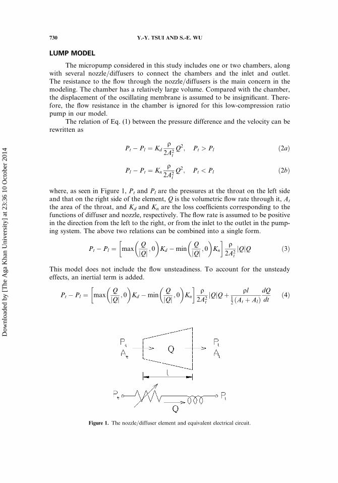
where, as seen in Figure 1, Pt and Pl are the pressures at the throat on the left sideand that on the right side of the element, Q is the volumetric flow rate through it, At
the area of the throat, and Kd and Kn are the loss coefficients corresponding to thefunctions of diffuser and nozzle, respectively. The flow rate is assumed to be positivein the direction from the left to the right, or from the inlet to the outlet in the pump-ing system. The above two relations can be combined into a single form.
Pt � Pl ¼ maxQ
jQj ; 0� �
Kd �minQ
jQj ; 0� �
Kn
� �q
2A2t
jQjQ ð3Þ
This model does not include the flow unsteadiness. To account for the unsteadyeffects, an inertial term is added.
Pt � Pl ¼ maxQ
jQj ; 0� �
Kd �minQ
jQj ; 0� �
Kn
� �q
2A2t
jQjQþ ql12 ðAt þ AlÞ
dQ
dtð4Þ
Figure 1. The nozzle=diffuser element and equivalent electrical circuit.
730 Y.-Y. TSUI AND S.-E. WU
Dow
nloa
ded
by [
The
Aga
Kha
n U
nive
rsity
] at
23:
36 1
0 O
ctob
er 2
014
In the last term, l is the length of the nozzle=diffuser element and Al is thecross-sectional area at the side opposite to the throat (see Figure 1).
The fluidic system can be represented by an electrical equivalent circuit with theflow rate analogous to the electrical current and the pressure to the voltage [17, 18].The above equation can be interpreted as an R-L circuit (see Figure 1).
DP ¼ RQþ LdQ
dtð5Þ
where R designates the flow resistance and L the inductance.
R ¼ maxQ
jQj ; 0� �
Kd �minQ
jQj ; 0� �
Kn
� �q
2A2t
jQj ð6aÞ
L ¼ ql12 ðAt þ AlÞ
ð6bÞ
The resistance is variable, depending on the flow rate and the flow direction, and theinductance is constant for a specific nozzle=diffuser.
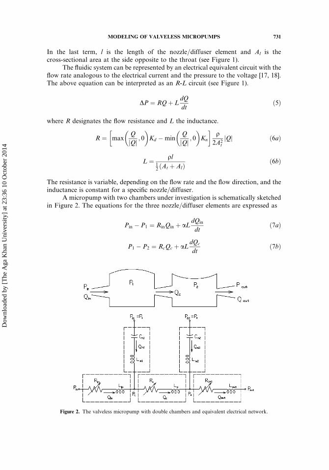
A micropump with two chambers under investigation is schematically sketchedin Figure 2. The equations for the three nozzle=diffuser elements are expressed as
Pin � P1 ¼ RinQin þ aLdQin
dtð7aÞ
P1 � P2 ¼ RcQc þ aLdQc
dtð7bÞ
Figure 2. The valveless micropump with double chambers and equivalent electrical network.
MODELING OF VALVELESS MICROPUMPS 731
Dow
nloa
ded
by [
The
Aga
Kha
n U
nive
rsity
] at
23:
36 1
0 O
ctob
er 2
014
P2 � Pout ¼ RoutQout þ aLdQout
dtð7cÞ
where Pin, P1, P2, and Pout denote the pressures at the inlet, chamber 1, chamber 2and the outlet, respectively, and Qin, Qc, and Qout the flow rates through the inlet,central, and outlet nozzle=diffusers. The constant a is 1 for the unsteady modeland 0 for the steady-state model. The inductances for the three nozzle=diffusersare the same because of identical elements used.
The membranes of the chambers are assumed to move in a harmonic motion,which is true if the driving frequency is much lower than the natural frequency of themembranes. Therefore, the conservation of mass for the two chambers gives
Qc �Qin ¼ Qm1 ¼ Vmx sinðxtÞ ð8aÞ
Qout �Qc ¼ Qm2 ¼ Vmx sinðxtþ dÞ ð8bÞ
where Vm is the volume change amplitude of the vibrating membranes, x the angularfrequency of the vibration, and d represents the difference in phase angle between thetwo membranes. The harmonic motion can be regarded as the homogeneous sol-ution of an L-C circuit:
LmdQm
dtþ 1
Cm
ZQmdt ¼ 0 ð9Þ
with LmCm¼ 1=x2 and Lm¼ qmtm=Am (tm is the thickness of the membrane and Am
the area), which is subject to the initial conditions.
Qmð0Þ ¼ Vmx sinðdÞ ð10aÞ
Q0mð0Þ ¼ Vmx
2 cosðdÞ ð10bÞ
The equivalent electrical network for the lumped system is displayed inFigure 2. It is noted that the force imposed on the membranes by the dynamic press-ure in the chambers is ignored in this simulation (P01¼P1 and P02¼P2 in thenetwork). For more accurate modeling, this effect can be included by imposingforcing terms P1�P01 and P2�P02 on the left-hand side of Eq. (9) for the twomembranes.
To close the problem, the loss coefficients Kn and Kd need to be determinedfrom either experiments or multidimensional calculations. The following correlationsare adopted from reference [25] because the same nozzle=diffuser is used.
Kd ¼ 1:315� 10�7Q�0:921 þ 0:5981 ð11aÞ
Kn ¼ 1:173� 10�6Q�0:8112 þ 1:204 ð11bÞ
The differential equations can be discretized using the Euler implicit scheme orany other higher-order schemes. As an example, a finite difference analogue of Eq. (5)
732 Y.-Y. TSUI AND S.-E. WU
Dow
nloa
ded
by [
The
Aga
Kha
n U
nive
rsity
] at
23:
36 1
0 O
ctob
er 2
014
is given as
LQ�Qo
Dtþ RoQ ¼ DP ð12Þ
where the superscripts o denote the last time values and the flow resistance Ro isestimated using the old flow rateQo. The systemof nonlinear algebraic equations arisingfrom Eqs. (7) and (8) can easily be solved forQin,Qc,Qout, P1, and P2 usingMATLAB.
MULTIDIMENSIONAL METHOD
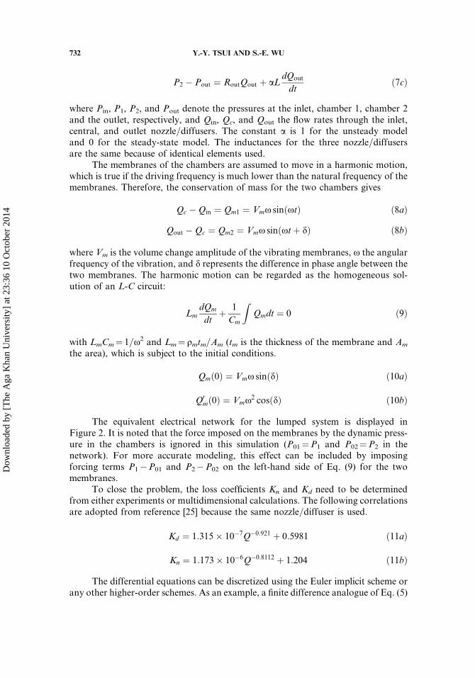
The geometrical configuration of the two-chamber system is illustrated inFigure 3. The membranes of the pump, driven by piezoelectric disks, oscillate in aharmonic motion. The deflection of the membranes is assumed to distribute in atrapezoidal profile.
wðr; tÞ ¼ �hm �Min 1;r0 � r
r0 � r1
� �cos xtð Þ ð13Þ
where r0 is the radius of the chamber, r1 that of the piezo disc, and hm the maximumdeflection at the center of the membrane. The maximum deflection is 1 mm, whereasthe height of the chamber is 0.2mm. Obviously, the change of the chamber volumecaused by the membrane vibration is insignificant. To simplify the simulation, thevolume of the chamber is assumed to be constant, i.e., the computational grid is fixedwithout motion. It is the oscillating velocity, obtained by differentiating the aboveequation, imposed on the membranes as boundary condition.
The flow is assumed to be incompressible. Due to the micro size of the pump,the Reynolds number is small, resulting in laminar flows. The conservation equationsof mass and momentum are given by
r � q~VV ¼ 0 ð14Þ
qq~VVqt
þr � ðq~VV � ~VVÞ ¼ �rPþ mr2~VV ð15Þ
Figure 3. Configuration of the micropump with double chambers.
MODELING OF VALVELESS MICROPUMPS 733
Dow
nloa
ded
by [
The
Aga
Kha
n U
nive
rsity
] at
23:
36 1
0 O
ctob
er 2
014
The differential equations are discretized using unstructured-grid techniques. Detailsof this method were described in references [26, 27]. A brief description is addressedin the following.
The equations are integrated over a control volume first. With the use ofdivergence theorem, the volume integrals of the convection and diffusion termsare transformed into surface integrals. The convective flux through the surface ofthe control volume is further approximated using a scheme blending the centraldifference and the upwind difference with a weighting biased toward the centraldifference. To handle the diffusive flux for the grid of arbitrary topology, anover-relaxed approach is employed.
All variables are collocated at the center of each cell. To avoid checkerboardoscillations arising in the non-staggered grid arrangement, the momentum interp-olation method is used to obtain the velocities and, thus, the mass flux on the surfaceof the control volume. Similar to the SIMPLE algorithm, a pressure-correctionequation is derived by forcing the mass fluxes through all the faces of the controlvolume to satisfy the continuity constraint. However, the SIMPLE algorithm relieson iteration around the momentum equation and the pressure-correction equation totackle the coupling between them. This procedure is time-consuming for unsteadycalculations. Therefore, the non-iterative, predictor-corrector procedure of PISO[28] is employed in this study. In the predictor step of this algorithm, the momentumequation is solved for the velocities using the prevailing pressure field. In the follow-ing corrector steps, the velocities and pressure are corrected via solving thepressure-correction equation obtained from mass conservation. In general, twocorrector steps are sufficient to get rid of the mass residual left by the velocities inthe predictor step.
As for boundary conditions, the no-slip condition is imposed on all solid wallsexcept for the membranes where, as described above, oscillating velocities are pre-scribed. Pressures are specified at the openings of the inlet and outlet. In order toderive the flows through the open boundaries from the given pressures, a method,which ensures mass conservation at the mesh cells next to the boundaries, wasadopted [25].
RESULTS AND DISCUSSION
Micropumps with single chamber and double chambers are under consider-ation. Zero pressure is assumed at the inlet and various back pressures are specifiedat the outlet. The membranes oscillate at a frequency of 2200Hz. Only half the pumpis considered in multidimensional calculations because of its geometric symmetry.Validation of the multidimensional method has been done in the study [25], inwhich a micropump with single chamber was considered. It was shown that with asuitable assumption of membrane deflection, good agreement with experimentalmeasurements of net flow rate at various back pressures is obtained.
Single Chamber Case
The net flow rates for a number of back pressures predicted by both thesteady and unsteady lump models and the multidimensional calculations are
734 Y.-Y. TSUI AND S.-E. WU
Dow
nloa
ded
by [
The
Aga
Kha
n U
nive
rsity
] at
23:
36 1
0 O
ctob
er 2
014
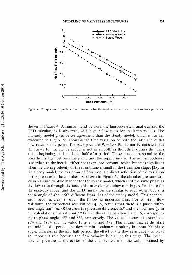
shown in Figure 4. A similar trend between the lumped-system analyses and theCFD calculations is observed, with higher flow rates for the lump models. Theunsteady model gives better agreement than the steady model, which is furtherevidenced in Figure 5a, showing the time variation of both the inlet and outletflow rates in one period for back pressure Pb¼ 5900 Pa. It can be detected thatthe curves for the steady model is not as smooth as the others during the timesat the beginning, end, and one half of a period. These times correspond to thetransition stages between the pump and the supply modes. The non-smoothnessis ascribed to the inertial effect not taken into account, which becomes significantwhen the driving velocity of the membrane is small in the transition stages [25]. Inthe steady model, the variation of flow rate is a direct reflection of the variationof the pressure in the chamber. As shown in Figure 5b, the chamber pressure var-ies in a sinusoidal-like manner for the steady model, which is of the same phase asthe flow rates through the nozzle=diffuser elements shown in Figure 5a. Those forthe unsteady model and the CFD simulation are similar to each other, but at aphase angle of about 90� different from that of the steady model. This phenom-enon becomes clear through the following understanding. For constant flowresistance, the theoretical solution of Eq. (5) reveals that there is a phase differ-ence angle tan�1xL=R between the pressure difference DP and the flow rate Q. Inour calculations, the ratio xL=R falls in the range between 1 and 15, correspond-ing to phase angles 45� and 86�, respectively. The value 1 occurs at around t¼T=4 and 3T=4 and the value 15 at t¼ 0 and T=2. This means that at the startand middle of a period, the flow inertia dominates, resulting in about 90� phaseangle; whereas, in the mid-half period, the effect of the flow resistance also playsan important role because the flow velocity is high at this stage. The instan-taneous pressure at the center of the chamber close to the wall, obtained by
Figure 4. Comparison of predicted net flow rates for the single chamber case at various back pressures.
MODELING OF VALVELESS MICROPUMPS 735
Dow
nloa
ded
by [
The
Aga
Kha
n U
nive
rsity
] at
23:
36 1
0 O
ctob
er 2
014
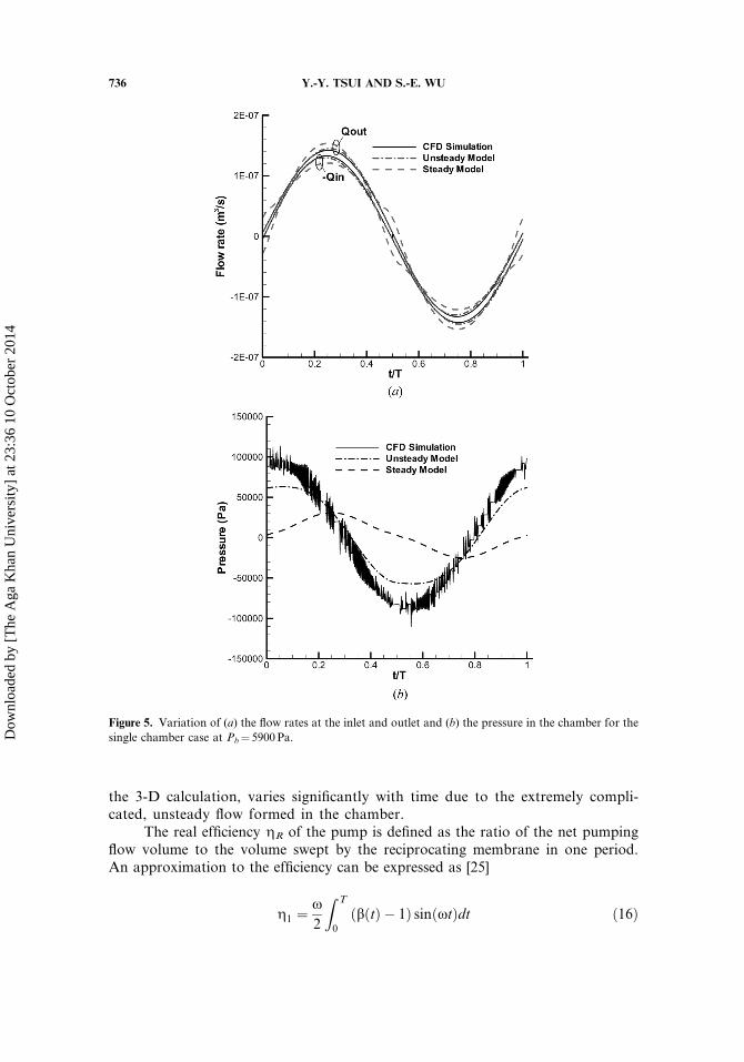
the 3-D calculation, varies significantly with time due to the extremely compli-cated, unsteady flow formed in the chamber.
The real efficiency gR of the pump is defined as the ratio of the net pumpingflow volume to the volume swept by the reciprocating membrane in one period.An approximation to the efficiency can be expressed as [25]
g1 ¼x2
Z T
0
ðbðtÞ � 1Þ sinðxtÞdt ð16Þ
Figure 5. Variation of (a) the flow rates at the inlet and outlet and (b) the pressure in the chamber for the
single chamber case at Pb¼ 5900Pa.
736 Y.-Y. TSUI AND S.-E. WU
Dow
nloa
ded
by [
The
Aga
Kha
n U
nive
rsity
] at
23:
36 1
0 O
ctob
er 2
014
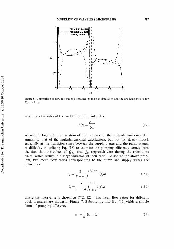
where b is the ratio of the outlet flux to the inlet flux.
bðtÞ ¼ Qout
Qinð17Þ
As seen in Figure 6, the variation of the flux ratio of the unsteady lump model issimilar to that of the multidimensional calculations, but not the steady model,especially at the transition times between the supply stages and the pump stages.A difficulty in utilizing Eq. (16) to estimate the pumping efficiency comes fromthe fact that the values of Qout and Qin approach zero during the transitionstimes, which results in a large variation of their ratio. To soothe the above prob-lem, two mean flow ratios corresponding to the pump and supply stages aredefined as
bp ¼2
T � 4a
Z T=2�a
a
bðtÞdt ð18aÞ
bs ¼2
T � 4a
Z T�a
T=2þa
bðtÞdt ð18bÞ
where the interval a is chosen as T=20 [25]. The mean flow ratios for differentback pressures are shown in Figure 7. Substituting into Eq. (16) yields a simpleform of pumping efficiency.
g2 ¼1
4ðbp � bsÞ ð19Þ
Figure 6. Comparison of flow rate ratios b obtained by the 3-D simulation and the two lump models for
Pb¼ 5900Pa.
MODELING OF VALVELESS MICROPUMPS 737
Dow
nloa
ded
by [
The
Aga
Kha
n U
nive
rsity
] at
23:
36 1
0 O
ctob
er 2
014
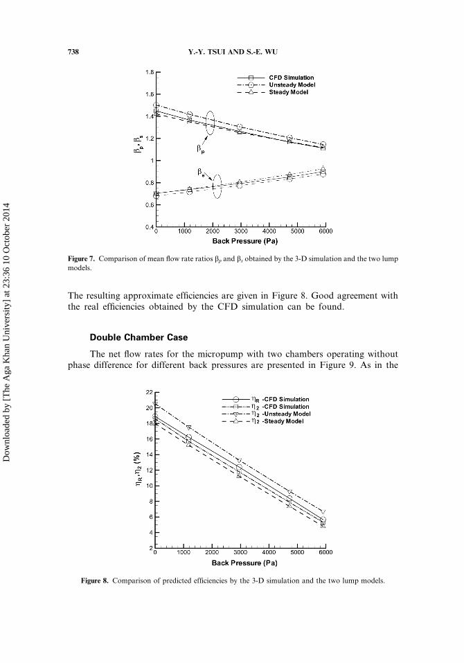
The resulting approximate efficiencies are given in Figure 8. Good agreement withthe real efficiencies obtained by the CFD simulation can be found.
Double Chamber Case
The net flow rates for the micropump with two chambers operating withoutphase difference for different back pressures are presented in Figure 9. As in the
Figure 7. Comparison of mean flow rate ratios bp and bs obtained by the 3-D simulation and the two lump
models.
Figure 8. Comparison of predicted efficiencies by the 3-D simulation and the two lump models.
738 Y.-Y. TSUI AND S.-E. WU
Dow
nloa
ded
by [
The
Aga
Kha
n U
nive
rsity
] at
23:
36 1
0 O
ctob
er 2
014
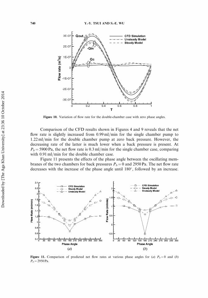
single chamber case, the predicted flow rates by the lump models are higher thanthe multidimensional calculations. However, the overpredictions are much higherfor the double chamber micropump. It is noted that the loss coefficients for thenozzle=diffusers used in the lump models are based on steady-state flows. As willbe seen latter, vortices may be formed periodically in the nozzle=diffusers and inthe chambers, which will hinder the flow through these elements and, thus, bringsabout higher loss. This effect is more significant with multiple chambers. Althoughthe net flow rates obtained by the steady model are close to the multidimensionalresults, it does not mean that the flow characteristics are better depicted by thismodel. The net pumping rate can be obtained by integrating the instantaneous flowrate through any one of the three nozzle=diffuser elements over one period. Asshown in Figure 10, the instantaneous flow rates through the three elements forthe unsteady model resemble those obtained by the CFD simulation. This isespecially evident by examining the variation of the flow through the center element(Qc). This flow rate represents the difference between those through the inletelement and the outlet one, i.e., Qc¼ (QinþQout)=2, which can be yielded by sub-tracting Eq. (8b) from Eq. (8a) with d¼ 0. The wavy patterns for the unsteadymodel and the CFD simulation are similar. Both vary in the same phase with afrequency two times that of the member. The values obtained by the two analysesare positive for the entire period, indicating that this center element always plays afunction of diffuser for this in-phase operation. The flow rate predicted by thesteady model varies in a half-wave form in both the pump stage and the supplystage. Its value is higher than that of the unsteady model in the middle regionsof the pump and supply stages, but becomes negative during the transition timesbetween the two stages. This results in lower net flow rate for the steady modelthan that for the unsteady model after integration and, thus, better agreement with
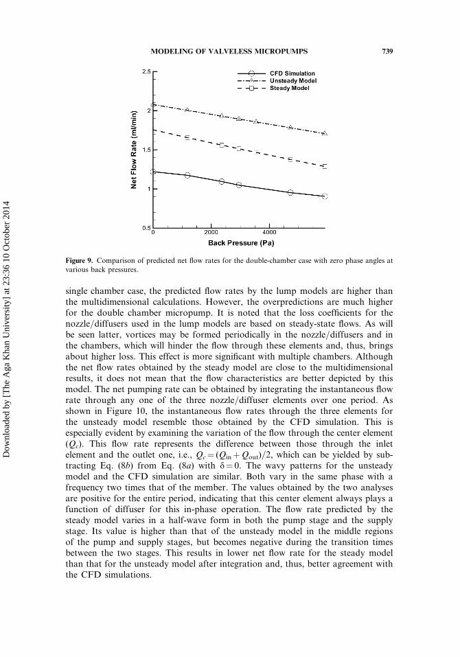
Figure 9. Comparison of predicted net flow rates for the double-chamber case with zero phase angles at
various back pressures.
MODELING OF VALVELESS MICROPUMPS 739
the CFD simulations.
Dow
nloa
ded
by [
The
Aga
Kha
n U
nive
rsity
] at
23:
36 1
0 O
ctob
er 2
014
Comparison of the CFD results shown in Figures 4 and 9 reveals that the netflow rate is slightly increased from 0.99ml=min for the single chamber pump to1.22ml=min for the double chamber pump at zero back pressure. However, thedecreasing rate of the latter is much lower when a back pressure is present. AtPb¼ 5900 Pa, the net flow rate is 0.3ml=min for the single chamber case, comparingwith 0.91ml=min for the double chamber case.
Figure 11 presents the effects of the phase angle between the oscillating mem-branes of the two chambers for back pressures Pb¼ 0 and 2950 Pa. The net flow ratedecreases with the increase of the phase angle until 180�, followed by an increase.
Figure 10. Variation of flow rate for the double-chamber case with zero phase angles.
Figure 11. Comparison of predicted net flow rates at various phase angles for (a) Pb¼ 0 and (b)
Pb¼ 2950Pa.
740 Y.-Y. TSUI AND S.-E. WU
Dow
nloa
ded
by [
The
Aga
Kha
n U
nive
rsity
] at
23:
36 1
0 O
ctob
er 2
014
The variation is symmetrical to the 180�. The results obtained by the differentmethods behave in a similar fashion, with the simple analyses giving higher netpumping rates. It has been noticed that in the study of Yang et al. [29], the net flowrate for a double chamber micropump varies in a sinusoidal-like manner, with a peakat 90� and negative values for the phase angles greater than 180�. It is believed thatthe cause of the characteristic difference between the two studies is mainly due to thelarge difference in compression ratio. The chamber height is 500 mm and themaximum deflection of the membrane is 250 mm in the study of Yang et al., whereasthe corresponding values are 200 mm and 1 mm in the present study. The large oscil-lating amplitude in the study of Yang et al. has considerable effect on the flow inthe pump with the resulting flow resistance greatly increased in both the nozzle=diffusers and the chambers. A difference exists in the flow resistance between thetwo chambers, which varies with the phase angle. However, the resistance is smalland the difference can be neglected in the present study because of the smallcompression ratio.
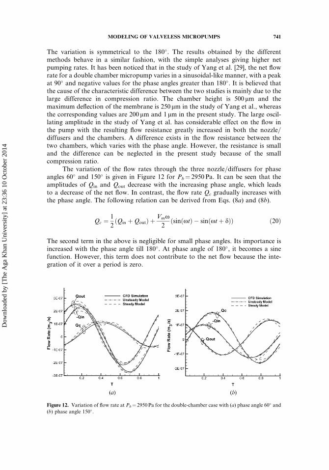
The variation of the flow rates through the three nozzle=diffusers for phaseangles 60� and 150� is given in Figure 12 for Pb¼ 2950 Pa. It can be seen that theamplitudes of Qin and Qout decrease with the increasing phase angle, which leadsto a decrease of the net flow. In contrast, the flow rate Qc gradually increases withthe phase angle. The following relation can be derived from Eqs. (8a) and (8b).
Qc ¼1
2ðQin þQoutÞ þ
Vmx2
ðsinðxtÞ � sinðxtþ dÞÞ ð20Þ
The second term in the above is negligible for small phase angles. Its importance isincreased with the phase angle till 180�. At phase angle of 180�, it becomes a sinefunction. However, this term does not contribute to the net flow because the inte-gration of it over a period is zero.
Figure 12. Variation of flow rate at Pb¼ 2950Pa for the double-chamber case with (a) phase angle 60� and(b) phase angle 150�.
MODELING OF VALVELESS MICROPUMPS 741
Dow
nloa
ded
by [
The
Aga
Kha
n U
nive
rsity
] at
23:
36 1
0 O
ctob
er 2
014
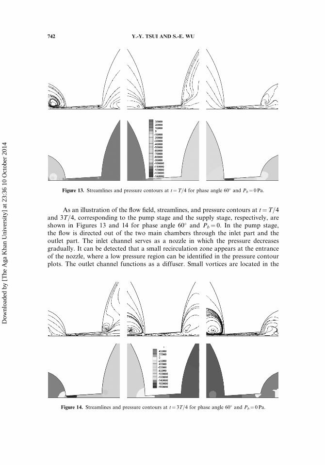
As an illustration of the flow field, streamlines, and pressure contours at t¼T=4and 3T=4, corresponding to the pump stage and the supply stage, respectively, areshown in Figures 13 and 14 for phase angle 60� and Pb¼ 0. In the pump stage,the flow is directed out of the two main chambers through the inlet part and theoutlet part. The inlet channel serves as a nozzle in which the pressure decreasesgradually. It can be detected that a small recirculation zone appears at the entranceof the nozzle, where a low pressure region can be identified in the pressure contourplots. The outlet channel functions as a diffuser. Small vortices are located in the
Figure 13. Streamlines and pressure contours at t¼T=4 for phase angle 60� and Pb¼ 0 Pa.
Figure 14. Streamlines and pressure contours at t¼ 3T=4 for phase angle 60� and Pb¼ 0 Pa.
742 Y.-Y. TSUI AND S.-E. WU
Dow
nloa
ded
by [
The
Aga
Kha
n U
nive
rsity
] at
23:
36 1
0 O
ctob
er 2
014
region near the throat. The pressure drops sharply first, followed by gradualrecovery. The pressure in the first main chamber is higher than that in the secondchamber with the central channel working as a diffuser. There is a large-scale vortexflow in the center region in the first chamber, which forces the flow to make a sharpturn to enter the inlet and the central elements. The recirculating flows in the nozzle=diffusers and the chambers are time-dependent and their appearance will causeadditional losses which are not accounted for in the lump models. At the supplystage, the functions of the three elements are reversed. The pressure in the secondchamber becomes higher. Small vortices can also be found in the nozzle=diffusersand larger-scale recirculating flows in the chambers.
CONCLUSION
Simple models based on the concept of lumped elements have been developedfor analysis of the flow in valveless micropump system. The models overcome theproblem of a non-unique solution and allow the use of multiple chambers. The iner-tial effect was included as an unsteady model. The results show that in comparisonwith the steady model, the unsteady model can portray the characteristics of the flowin the pumping system more closely as evidenced by comparing with the CFDsimulation. The net flows obtained by the lump models are higher than those bythe multidimensional calculations due to the complicated recirculating flows in thepump causing additional losses. It was shown that the net pumping flow is increasedonly marginally when the system is changed from the single chamber to the doublechamber. However, the double-chamber system has a higher capability to resist thedecline in pumping effectiveness, as back pressures are imposed at the outlet. The netflow is reduced when a phase angle exists between the vibrating membranes of thetwo chambers. This is in contrast to other studies in which there exists a peak valueof net flow at a certain phase angle. The cause of this difference is owing to theinsignificant compression ratio assumed in the present pump configuration. For asystem with high compression ratio the flow resistance in the pump chamber mustbe accounted for in the model. Micropumps with three chambers have been seenin biological sample processing and drug delivery applications. The working of thesepumping systems is based on the peristalsis concept. Extension of the present modelsto the peristaltic micropumps is straightforward and such work is under way.
REFERENCES
1. N.-T. Nguyen, X. Huang, and T. K. Chuan, MEMS-Micropumps: A Review, ASME J.Fluids Eng., vol. 24, pp. 384–392, 2002.
2. D. J. Laser and J. G. Santiago, A Review of Micropumps, J. Micromech. Microeng., vol. 4,pp. R35–R64, 2004.
3. P. Woias, Micropumps—Past, Progress and Future Prospects, Sens. Actuator B, vol. 105,pp. 28–38, 2005.
4. G. H. Priestman, A Study of Vortex Throttles Part 1: Experimental, Proc. Inst. Mech.Eng., vol. 21, pp. 331–336, 1987a.
5. G. H. Priestman, A Study of Vortex Throttles Part 2: Viscid Flow Analysis, Proc. Inst.Mech. Eng., vol. 21, pp. 337–345, 1987b.
MODELING OF VALVELESS MICROPUMPS 743
Dow
nloa
ded
by [
The
Aga
Kha
n U
nive
rsity
] at
23:
36 1
0 O
ctob
er 2
014
6. A. A. Kulkarni, V. V. Ranade, R. Rajeev, and S. B. Koganti, CFD Simulation of Flow inVortex Diodes, AIChE J., vol. 54, pp. 1139–1152, 2008.
7. M. Anduze, S. Colin, R. Caen, H. Camon, V. Conedera, and T. Do Conto, Analysis andTesting of a Fluidic Vortex Microdiode, J. Micromech. Microeng., vol. 11, pp. 108–112,2001.
8. N. Tesla, Vavular Conduit, U.S. Patent No. 1329559, 1920.9. F. K. Forster, R. L. Bardell, M. A. Afromowitz, N. R. Sharma, and A. Blanchard,
Design, Fabrication and Testing of Fixed-Valve Micro-Pumps, In Proc. of the ASMEFluids Engineering Division, FED, vol. 234, 1995 IMECE, pp. 39–44, 1995.
10. M. Turowski, Z. Chen, and A. Przekwas, Automated Generation of CompactModels for Fluidic Microsystems, Analog Integr. Circ. Sig. Process, vol. 29, pp.
27–36, 2001.11. A. R. Gamboa, C. J. Morris, and F. K. Forster, Improvements in Fixed-Valve
Micropump Performance Through Shape Optimization of Valves, ASME J. FluidsEng., vol. 127, pp. 339–346, 2005.
12. E. Stemme and G. Stemme, A Valveless Diffuser=Nozzle-Based Fluid Pump, Sens.Actuator A, vol. 39, pp. 159–167, 1993.
13. T. Gerlach and H. Wurmus, Working Principle and Performance of the DynamicMicropump, Sens. Actuator A, vol. 50, pp. 135–140, 1995.
14. A. Olsson, G. Stemme, and E. Stemme, Diffuser-Element Design Investigation forValve-Less Pumps, Sens. Actuator A, vol. 57, pp. 137–143, 1996.
15. A. Olsson, G. Stemme, and E. Stemme, Numerical and Experimental Studies ofFlat-Walled Diffuser Elements for Valve-less Micropumps, Sens. Actuator A, vol. 84,pp. 165–175, 2000.
16. V. Singhal, S. V. Garimella, and J. Y. Murthy, Low Reynolds Number Flow ThroughNozzle-Diffuser Elements in Valveless Micropumps, Sens. Actuator A, vol. 113, pp.226–235, 2004.
17. T. Bourouina and J.-P. Grandchamp, Modeling Micopumps with Electrical EquivalentNetworks, J. Micromech. Microeng., vol. 6, pp. 398–404, 1996.
18. E. Morganti, I. Fuduli, A. Montefusco, M. Petasecca, and G. U. Pignatel, SPICE Model-ing and Design Optimization of Micropumps, Intern. J. Environ. Anal. Chem., vol. 85,pp. 687–698, 2005.
19. A. Ullmann, The Piezoelectric Valve-Less Pump—Performance Enhancement Analysis,Sens. Actuator A, vol. 69, pp. 97–105, 1998.
20. A. Olsson, G. Stemme, and E. Stemme, A Numerical Design Study of the ValvelessDiffuser Pump using a Lumped-Mass Model, J. Micromech. Microeng., vol. 9,pp. 34–44, 1999.
21. L. S. Pan, T. Y. Ng, G. R. Liu, K. Y. Lam, and T. Y. Jiang, Analytical Solutions for theDynamic Analysis of a Valveless Micropump—a Fluid-Membrane Coupling Study, Sens.Actuator A, vol. 93, pp. 173–181, 2001.
22. L. S. Pan, T. Y. Ng, X. H. Wu, and H. P. Lee, Analysis of Valveless Micropumps withInertial Effects, J. Micromech. Microeng., vol. 13, pp. 390–399, 2003.
23. A. Ullmann, I. Fono, and Y. Taitel, A Piezoelectric Valve-Less Pump—Dynamic Model,ASME J. Fluids Eng., vol. 123, pp. 92–98, 2001.
24. A. Ullmann and I. Fono, The Piezoelectric Valve-Less Pump—Improved DynamicModel, J. Microelectromech. Syst., vol. 11, pp. 655–664, 2002.
25. Y.-Y. Tsui and S.-L. Lu, Evaluation of the Performance of a Valveless Micropump byCFD and Lumped-System Analyses, Sens. Actuator A, vol. 148, pp. 138–148, 2008.
26. Y.-Y. Tsui and Y.-F. Pan, A Pressure-Correction Method for Incompressible Flows usingUnstructured Meshes, Numer. Heat Transfer B, vol. 49, pp. 43–65, 2006.
744 Y.-Y. TSUI AND S.-E. WU
Dow
nloa
ded
by [
The
Aga
Kha
n U
nive
rsity
] at
23:
36 1
0 O
ctob
er 2
014
27. Y.-Y. Tsui and T.-C. Wu, A Pressure-Based Unstructured-Grid Algorithm usingHigh-Resolution Schemes for All-Speed Flows, Numer. Heat Transfer B, vol. 53,
pp. 75–96, 2008.28. R. I. Issa, Solution of the Implicitly Discretised Fluid Flow Equation by
Operator-Splitting, J. Comput. Physics, vol. 62, pp. 40–65, 1986.29. K.-S. Yang, I.-Y. Chen, and C.-C. Wang, Performance of Nozzle=Diffuser Micro- Pumps
Subject to Parallel and Series Combinations, Chem. Eng. Technol., vol. 29, pp. 703–710,2006.
MODELING OF VALVELESS MICROPUMPS 745
Dow
nloa
ded
by [
The
Aga
Kha
n U
nive
rsity
] at
23:
36 1
0 O
ctob
er 2
014