Embed Size (px)
Citation preview
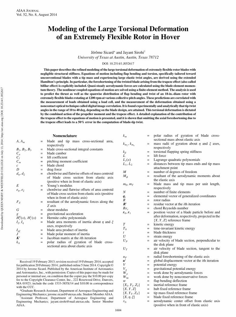
Modeling of the Large Torsional Deformationof an Extremely Flexible Rotor in Hover
Jérôme Sicard∗ and Jayant Sirohi†
University of Texas at Austin, Austin, Texas 78712
DOI: 10.2514/1.J052617
This paper describes the refinedmodeling of the large torsional deformation of extremely flexible rotor bladeswith
negligible structural stiffness. Equations of motion including flap bending and torsion, specifically tailored toward
unconventional blades with a tip mass and experiencing large elastic twist angles, are derived using the extended
Hamilton’s principle. In particular, the foreshortening of the twisted blade arising from the trapeze effect (also called
bifilar effect) is explicitly included. Quasi-steady aerodynamic forces are calculated using the blade element momen-
tum theory. The nonlinear coupled equations of motion are solved using a finite-elementmethod. The analysis is used
to predict the thrust as well as the spanwise distribution of flap bending and twist of an 18-in.-diam rotor with
extremely flexible blades rotating at 1200 rpmat various collective pitch angles. These predictions are correlatedwith
the measurement of loads obtained using a load cell, and the measurement of the deformation obtained using a
noncontact optical technique called digital image correlation. It is found experimentally and analytically that tip twist
angles in the range of 10 to 40 deg, depending on the blade design, are attained. This torsional deformation is dictated
by the combined action of the propeller moment and the trapeze effect. A detailed explanation of the contribution of
the trapeze effect to the equations of motion is presented, and it is shown that omitting the axial foreshortening due to
the trapeze effect leads to a 50% error in the computation of blade-tip twist.
Nomenclature
A, Am = blade and tip mass cross-sectional area,respectively
B1, B2, B3 = blade cross-sectional integral constantsCa = blade camberCl = lift coefficientCm = pitching moment coefficientc = blade chordD = drag forcedη, dξ = chordwise and flatwise offsets ofmass centroid
of blade cross section from elastic axis(positive when in front of elastic axis)
E = Young’s moduluseη, eξ = chordwise and flatwise offsets of area centroid
of blade cross section from elastic axis (positivewhen in front of elastic axis)
FZ = resultant of the aerodynamic forces along theZ axis
G = shear modulusg = gravitational accelerationH0i x, H1
i x = Hermite cubic polynomialsIξ, Iη = blade area moments of inertia about η and ξ
axes, respectivelyIηξ = blade area product of inertiaJ = blade polar moment of inertiaKi = Jacobian matrix at the ith iterationkA = polar radius of gyration of blade cross-
sectional area about elastic axis
km = polar radius of gyration of blade cross-sectional mass about elastic axis
kmξ, kmη
= mass radii of gyration about η and ξ axes,respectively
kβ = torsional flapping spring stiffnessL = lift forceLix = Lagrange quadratic polynomialsL1, L2 = distances between tip mass ends and tip mass
attachment pointM = number of degrees of freedomMϕ = resultant of the aerodynamic moments about
the elastic axism0, mT = blade mass and tip mass per unit length,
respectivelyN = number of finite elementsqi = elemental vector of generalized coordinatesR = rotor radiusRi = residue vector at the ith iterationRec = chord Reynolds numberr0, r1 = position vector of a blade particle before and
after deformation, respectively, projected in thefX; Y; Zg reference frame
T = kinetic energyT0 = time-invariant kinetic energyt = blade thicknessU = strain energyUP = air velocity of blade section, perpendicular to
the disk planeUT = air velocity of blade section, tangent to the
disk planeuF = radial foreshortening of the elastic axisui = global displacement vector at the ith iterationV = potential energyVg = gravitational potential energyWa = work done by aerodynamic forcesWnc = work done by nonconservative forcesw = flap bending deflectionfXI; YI; ZIg = inertial reference framefX; Y; Zg = hub fixed reference framefX; YT; ZTg = tip mass fixed reference framefX; η; ξg = blade fixed reference framexA = aerodynamic center offset from elastic axis
(positive when in front of elastic axis)
Received 19 February 2013; revision received 19 February 2014; acceptedfor publication 20 February 2014; published online 5 June 2014. Copyright©2014 by Jerome Sicard. Published by the American Institute of AeronauticsandAstronautics, Inc., with permission. Copies of this paper may be made forpersonal or internal use, on condition that the copier pay the $10.00 per-copyfee to the Copyright Clearance Center, Inc., 222 Rosewood Drive, Danvers,MA 01923; include the code 1533-385X/14 and $10.00 in correspondencewith the CCC.
*Graduate Research Assistant, Department of Aerospace Engineering andEngineeringMechanics; [email protected]. StudentMember AIAA.
†Assistant Professor, Department of Aerospace Engineering andEngineering Mechanics; [email protected]. Senior MemberAIAA.
1604
AIAA JOURNALVol. 52, No. 8, August 2014
Dow
nloa
ded
by Q
UE
EN
MA
RY
& W
EST
FIE
LD
CO
LL
EG
E o
n Ju
ly 1
3, 2
014
| http
://ar
c.ai
aa.o
rg |
DO
I: 1
0.25
14/1
.J05
2617

x0 = blade root cutoutϵij = strain tensor in a Lagrangian senseϵ = parameter of the order of the normalized flap
bending deflectionηT , ξT = chordwise and flatwise offsets of tip mass
attachment point from elastic axis (positivewhen in front of elastic axis)
θ = local pitch angleθ0 = collective pitch angleθind = index angle between tip mass longitudinal axis
and blade chordλi = line-search algorithm constant at the ith
iterationνβ = rotating flap frequencyνθ = rotating torsional frequencyρ, ρm = blade and tip mass density, respectivelyσ = rotor solidityϕ = elastic twist angleχ, λ = bound variablesψ = induced angle of attackΩ = rotational speed
Subscripts
b, m = quantity corresponding to the blade and the tipmass, respectively
R = quantity is evaluated at blade tip
Superscript
0 = space derivative
I. Introduction
ROTARY-WING micro aerial vehicles (MAVs) have becomeincreasingly popular over the past decade because they are
capable of performing missions that conventional manned vehiclesor larger unmanned aerial vehicles cannot [1–3]. Specifically, theirunique ability to take off and land vertically, hover, and fly at very lowadvance ratios makes them perfectly suited to indoor surveillance orreconnaissance missions. Flight in these cluttered environmentsposes several challenges, such as increased danger of blade impactwith obstacles and limited access to confined areas due to the largerotor diameter.The extremely flexible morphing rotor was proposed as a potential
solution to some of these issues. This rotor features blades that areso flexible that they can be rolled up and stowed in the rotor hub.In this way, the rotor diameter can be changed in flight; increasingthe diameter can increase the hover endurance and decreasing thediameter can allow access to confined spaces. The full retraction ofthe blades is also advantageous for storage and ground transportationof the MAV. Furthermore, the probability of survival of the vehicleupon collision with an object is increased by the high compliance ofthe rotor blades. In such an event, the rotor blade can experience largedeformations and elastically recover its original shape. Sicard andSirohi [4] designed and tested several prototypes of 18-in.-diamextremely flexible rotors in hover.The prototypes featured constant chord blades with a thin circular-
arc airfoil section. The blades were fabricated using a carbon-fibercomposite with a polyurethane epoxy resin. By choosing resins ofdifferent shear stiffness and by varying the orientation of the compos-ite plies, rotor blades with different bending and torsional flexibilitywere realized. A two-bladed rotor with blades that are extremelyflexible in flap bending and torsion is shown in Fig. 1a. Elastic flexi-bility in flap bending does not have a major impact on the behaviorof the rotor due to the stiffening effect of centrifugal forces (as in thecase of an articulated rotor, for example). However, torsionalflexibility plays a key role in the steady-state as well as dynamicbehavior of a rotor blade. Decreasing the torsional stiffness makes arotor blade prone to pitch–flap flutter. Therefore, the flexible rotorblade featured a tip mass designed to provide stiffness and
stabilization through the action of centrifugal forces. However, thepropeller moments acting on the rotor blade and tip mass induced alarge, spanwise negative twist. Although a limited amount of nega-tive twist, on the order of 12 to 15 deg per rotor radius, can befavorable for the hover efficiency of amicrohelicopter [5], Sicard andSirohi [4] showed that flexible blades experienced twist rates of up to40 deg per rotor radius at high blade loading, leading to poor figuresof merit. They experimentally investigated several designs of tor-sionally soft rotors by varying the orientation of the tip mass. Theyshowed that the negative induced twist could be alleviated byorienting the tip mass chordwise and introducing an index anglebetween the blade chord and the minor principal axis of inertia of thetip body. This blade, termed as the “design BP”, is shown rotating at1500 rpm in Fig. 1b. Further optimization of the flexible rotorrequires accurate prediction of its deformation given a set of geomet-rical parameters.The objective of this paper is to describe an aeroelastic analysis
specifically developed tomodel the large, steady-state deformation ofa torsionally soft rotor. Thismodel can be used to analytically explorethe effect of design parameters on these unconventional rotor blades,with the goal of optimizing specific performance metrics.
II. State of the Art and Present Approach
The analytical study of rotating beams has sparked a great deal ofinterest throughout the second half of the last century, particularly tosupport the development of rotorcraft aeromechanics analyses. Oneof the initial studies was conducted by Houbolt and Brooks [6] who
a) Flexible rotor at rest, mounted on hover test stand
Tip body
Index angle
b) Flexible blade rotating at 1500 RPM
Fig. 1 18-in.-diam rotor (design BP) with extremely flexible blades [4].
SICARD AND SIROHI 1605
Dow
nloa
ded
by Q
UE
EN
MA
RY
& W
EST
FIE
LD
CO
LL
EG
E o
n Ju
ly 1
3, 2
014
| http
://ar
c.ai
aa.o
rg |
DO
I: 1
0.25
14/1
.J05
2617

derived the partial differential equations of motion for the coupledbending and torsion of twisted nonuniform beams using a linearanalysis. As the significance of nonlinear terms in the aeroelasticityof rotary-wings was discovered, nonlinear equations of motion forcombined flap bending, lead–lag bending, torsion, and extension oftwisted nonuniform rotor blades were derived independently byseveral authors [7–9]. These theories, based on truncation schemesand accurate to second order, relied on the restriction that normalizedbending deflections and angles of twist were small with respect tounity. The equations of motion were derived assuming a displace-ment field, and the rotor blades were modeled as beam elements forwhich the cross-sectional constants were calculated at the elasticaxis. Then, in the mid-1990s, studies addressing the arbitrarily largedisplacements and rotations of composite rotor blades were derived,using a geometrically exact beam theory [10,11] or a multibodyformulation [12]. Nowadays, most modern rotor blade aeromechan-ics analyses stem from one of these two approaches. More details onthe development of structural dynamics modeling of rotor blades canbe found in a review by Datta et al. [13] and a report by Johnson [14].Although it is understood that the deformation of rotor blades with
negligible structural stiffness can be accurately predicted using ananalysis valid for large displacements and large rotations (seeHodges[11] or Bauchau and Kang [12] for instance), the purpose of thepresent work is to show that good predictions can be obtained byusing a model based on a Hamiltonian formulation along with anappropriate ordering scheme, including typical physical effectsassociated with large angles of twist. In particular, for blades that areextremely flexible in torsion, the elastic twist angles can be large, andthe trapeze effect becomes important. A limited number of aeroelasticanalyses have been developed in the past to specifically addressrotor blades with negligible structural stiffness. Goldman [15] andWinston [16,17] analyzed and tested flexible rotor blades constructedof a thin fabric airfoil supported by cables at the leading and trailingedges. Preliminary stability results were obtained using a simplifiedanalyticalmodel and assuming the first coupled flapwise bending andtorsional mode shapes of the blade.The present paper has two goals. The first objective is to demon-
strate how an aeroelastic analysis with two degrees of freedom (flapbending and twist), and whose equations are truncated consistentlywith an ordering scheme, can accurately predict the deformationsof a rotor blade with negligible torsional stiffness. The secondobjective is to investigate the importance of the terms arising fromthe trapeze effect for torsionally soft rotors and their contribution tothe calculated twist and overall deflection predictions. Accordingly,the nonlinear, steady-state aeroelastic equations for combined flapbending and twist of a rotor blade are derived. Throughout thederivation, special attention is given to the terms associated with largetwist angles. In particular, the truncation scheme is chosen such that theelastic twist angle is considered to be of the sameorder ofmagnitude asthe collective pitch angle. In addition, the foreshortening due to thetrapeze effect is explicitly included. The analysis also includes thekinetic and potential energies of a tip body that is required to ensurestability. The equations of motion are solved using the finite-elementmethod. Analytical predictions of flap bending and twist deformationare correlatedwithmeasurements obtained using a noncontact, opticaltechnique called digital image correlation [18,19].
III. Experimental Setup
A digital image correlation (DIC) system was used to measure thedeformation of the flexible rotor blades spinning at 1200 rpm on ahover test stand.
A. Digital-Image-Correlation Measurement Setup
DIC is a noncontact, opticalmeasurement technique that combinesphotogrammetry and image correlation. In the DIC technique, twodigital cameras are arranged to capture stereoscopic images of anobject. The positions of the cameras are calibrated with a target ofknown geometry, yielding a photogrammetric mapping function.Images of the object are captured before and after loads are applied.Cross-correlation of the images, along with the mapping function,
yields a three-dimensional deformation map of the object. Details ofthis technique applied to measure rotor blade deformation are givenin [18,19]. From the DICmeasurements, the spanwise distribution offlap bending of the rotor blade elastic axis as well as the elastic twistwere extracted.In the present study, the flexible rotor was tested in hover, on a 1.2-
m-tall rotor test stand (Fig. 2), designed and fabricated in-house (seedetails in [4]). Two digital cameras, Imager ProX 2M charge-coupled-device (CCD) cameras, were arranged so that they focuson a rotor blade at a specific azimuthal angle. Each camera had aresolution of 1600 × 1200 pixels, a maximum imaging frequency of29.9 frames per second, and an exposure time varying from 500 ns to1000 s. Their 14 bit CCD sensor had a sensitivity of 16,384 graylevels. The lenses mounted on the cameras were Nikon AF Nikkor50mm f∕1.8D, with an aperture varying between f∕1.8 and f∕22. AScheimpflug adapter was also added to the lens to keep the entirerotor blade span in focus. A signal from a 1∕rev sensor on the rotorshaft was used to synchronize the image capture with the rotorrotation. This signal was also sent to a 10 W xenon stroboscope,effectively illuminating the rotor once per revolution. The camerashutters were kept open over several rotor revolutions, creatingmultiple exposures of the rotor blade on the CCD sensor. The captureof multiple exposures resulted in a higher-intensity image thanpossible with only one exposure of the rotor blade. A commerciallyavailable DIC software (LaVision DaVis 7.2 — StrainMaster 3D)was used to process the images and to calculate surface heights aswell as deformation maps. A postprocessor written in-house wasused to extract the flap bending and torsional deformations alongthe blade span. The rotor test stand also featured a six-componentstrain gauge load cell (ATI Mini40E), with a full-scale rating of 5 lbin the thrust direction, that continuously recorded rotor forces andmoments in the fixed frame.
B. Flexible Rotor
The flexible rotor blades used in this study were fabricatedout of composite material comprising two plies of a carbon-fiberfabric (CST CF-131-1k, 2.9 oz∕yd2 0∕90 deg plain weave) and a
Fig. 2 Hover test stand equipped with CCD cameras, stroboscope, andlaser for root pitch angle measurement.
1606 SICARD AND SIROHI
Dow
nloa
ded
by Q
UE
EN
MA
RY
& W
EST
FIE
LD
CO
LL
EG
E o
n Ju
ly 1
3, 2
014
| http
://ar
c.ai
aa.o
rg |
DO
I: 1
0.25
14/1
.J05
2617

polyurethane matrix (Aircraft Spruce AlphaPoxy). Each ply wasarranged such that the fibers of the cloth made an angle of 45∕ −45 deg relative to the blade span. This combination of ply orientationandmaterial shearmoduluswas found to be themost favorable to reelthe blade into a cylinder with minimal radius of curvature. Althoughthe choice of the matrix resulted in a blade soft in torsion, the angleof the fibers lowered the bending stiffness to accommodate the roll-upof the blade. The composite was cured at room temperature in acompression mold that had the desired airfoil shape and bladeplanform. The blades had a constant chord, thin circular-arc airfoilsection, and a chordwise-oriented cylindrical mass attached at theblade tip (see Fig. 3; this design is labeled as blade BP in [4]). Thechordwise position of the tipmass attachment point could be adjustedbetween the two rod ends, varying the lengths L1 and L2. A two-bladed rotor was created by attaching the flexible blades to a rigidhub. Table 1 summarizes the parameters of the flexible rotor. Normal-ized flap bending stiffness, lead–lag bending stiffness, and torsionalstiffness are shown in Table 2. For comparison, the normalizedtorsional stiffness of a blade having the same cross section butfabricated out of AGP370-5H/3501 carbon-fiber composite is equalto 6.64. Therefore, the low-shear-modulus polyurethane matrixresults in a decrease in torsional stiffness by three orders of magni-tude. Also shown in Table 2 are the first rotating torsional and flapfrequencies of the extremely flexible blade. Note that a clampedcondition of the pitch degree of freedom at the root, as it is imposed inthe present study, typically leads to high torsional frequencies forconventionally stiff, full-scale rotor blades. However, it can be seen inTable 2 that the rotating torsional frequency of the flexible rotor bladeis on the order of 3.3∕rev.The bottom surface of each blade was painted with a high-contrast
random speckle pattern for the DIC measurements (Fig. 4). The
speckle size ranged from approximately 0.15 to 1.95 mm, chosen foroptimum accuracy based on the resolution of the digital cameras usedin DIC.
IV. Analytical Model
The analytical model was derived using the extended Hamilton’sprinciple. A structural model based on engineering beam theory wasused to determine the kinetic energy and strain energy of the rotorblade as well as the tip mass. The blade deformation was assumedto have only two degrees of freedom: flap bending and torsion.Extensional elongation was neglected; however, the axial displace-ment, or foreshortening of the elastic axis, induced by the combinedaction of bending and torsion, was explicitly included. Coordinatesystems were defined with respect to the undeformed and deformedpositions of the blade, and an ordering scheme was proposed toeliminate higher-order terms. The aerodynamic model included onlyquasi-steady forcing terms. Finally, the equations of motion weresolved using the finite-element method.The extended Hamilton’s principle states thatIf
δqijt1 δqijt2 0; for i 1; : : : ;M
then Zt2
t1
δT − δV δWnc dt 0 (1)
where δqi are the generalized coordinates; δT and δV are thevariations of kinetic and potential energies, respectively; and δWnc isthe virtual work done by nonconservative forces. By retaining onlytime-invariant terms, and including the kinetic and potential energyassociatedwith a tipmass,we obtain the equation governing the static(or steady-state) equilibrium of the rotor blade:
δT0 − δU − δVg δWab δT0 − δVgm 0 (2)
where δT0, δU, and δVg are the variations of time-invariant kineticenergy, strain energy, and gravitational potential energy, respectively.δWa is the virtual work done by aerodynamic forces. The subscriptsband m indicate the quantities corresponding to the blade and the tipmass, respectively.
A. Coordinate System
Three coordinate systems were used in the present analysis.Figure 5a shows the schematic of a rotor blade before and after flapbending and torsional deformation. fXI; YI; ZIg is an inertial referenceframe. fX; Y; Zg is attached to the undeformed position of the blade,with X coincident with the elastic axis and Z aligned with the rotorshaft. Finally, fX; η; ξg (Fig. 5b) is attached to the circular-arc airfoilcross section, rotated by the angle θ with respect to fX; Y; Zg.Throughout this analysis, the flap bending deflection w was
defined as the displacement, projected on theZ axis, of points locatedalong the elastic axis of the blade. The local pitch angle θwas the sumof the blade collective pitch θ0 and the local elastic twist ϕ:
Fig. 3 Planform of flexible-blade BP.
Table 1 Flexible rotor parameters
Airfoil Circular arc
Rotor radius R, in. (m) 9 (0.229)Root cutout x0, in. (m) 2.323 (0.059)Chord c, in. (m) 0.9 (0.023)Camber Ca, % of c 7.5Thickness t, % of c 1.39Rotor solidity σ 0.064Total mass m, oz (g) 0.160 (4.53)Mass per unit length (m0), oz · in:
−1 (kg · m−1) 0.0116 (0.013)Tip mass mT , oz (g) 0.072 (2.03)Length of the tip mass LT , in. (m) 1 (0.0254)Chordwise coordinate of the tip massattachment point (ηT ), % of c
12
Tip mass end offset from attachmentpoint (L1), % of LT
30
Rotational speed Ω, rpm 1200Tip Reynolds number Rec 46,160
Table 2 Flexible-blade normalized stiffnesses
Flap bending stiffnessEIη
m0Ω2R4 9.65 × 10⁻²
Lead–lag bending stiffnessEIξ
m0Ω2R4 2.54 × 101
Torsional stiffness GJm0Ω2R4 1.00 × 10⁻³
First rotating torsional frequency, /rev νθ 3.3First rotating flap frequency, /rev νβ 1.1
Fig. 4 High-contrast random pattern on the bottom surface of flexiblerotor blade.
SICARD AND SIROHI 1607
Dow
nloa
ded
by Q
UE
EN
MA
RY
& W
EST
FIE
LD
CO
LL
EG
E o
n Ju
ly 1
3, 2
014
| http
://ar
c.ai
aa.o
rg |
DO
I: 1
0.25
14/1
.J05
2617

θx θ0 ϕx (3)
B. Structural Model
The structural model of the rotor blade was based on engineeringbeam theory. Kinetic and potential energies of the rotor blade as wellas tip mass were found based on the deformations, in conjunctionwith an ordering scheme. The key aspect of the structural model is theinclusion of the trapeze effect due to the low torsional stiffness of therotor blade.
1. Trapeze Effect
Conventional helicopter rotor blades are relatively stiff in torsion,due to the skin of the blade acting as a closed torque box. Theflexibility in torsion is due predominantly to the control system stiff-ness. Therefore, propeller moments dominate the torsional deforma-tion of a conventional blade. In contrast, the flexible rotor bladeunder consideration has a thin circular-arc airfoil and is composedof a carbon-fiber composite with a low-shear-modulus matrix.Consequently, the flexible blade has a very low torsional stiffness,and twisting of the rotor blade results in a kinematic radialforeshortening. This nonlinear effect is called the trapeze (or bifilar)effect [20]. It plays an important role in the torsional dynamics of aflexible rotor. The relation between the angle of twist and the inducedradial displacement can be illustrated by considering the case of arotor blade composed of two inextensible cables at the leading andtrailing edges, connected at the tip by a rigid link, as shown in Fig. 6.The Pythagorean theorem applied to Fig. 6b gives
dx2c
2ϕxdx−c
2ϕx
2
dxuFx−uFxdx2 (4)
Dividing through by dx and applying theTaylor–Lagrange expansionfor small ϕ 0, we get
u 0F 1 −1 −
c2
8ϕ 0 Oϕ 02
(5)
Integration along the blade span leads to the radial foreshortening dueto twist:
uF Zx
0
c2
8ϕ 02 dx (6)
Although this expression will vary depending on the exact geometryof the rotor blade, we assume it to hold for the present case.
2. Ordering Scheme
As the Hamilton principle is applied [Eq. (2)], it is important toverify that the orders of approximation of the kinetic and potentialenergies, as well as the work done by nonconservative forces, are thesame. Along the lines of previous studies [7–9], we defined anordering scheme, where each physical quantity was compared to thenormalized flap bending deflection w∕R, assumed to be of order ϵ.However, in the present analysis, the elastic twist angle ϕ wasassumed to be of the same order as the collective pitch angle θ0 (i.e.,of order 1). The ordering scheme is summarized in Table 3.
3. Strain Energy
The general formulation for the variation of the rotor blade strainenergy is
δUb ZR
ZZAEϵxxδϵxx 4Gϵxηδϵxη 4Gϵxξδϵxξ dη dξ dx
(7)
The integrand is a function of the strain tensor ϵ associated with theflap bending and torsional deformation of the rotor blade, which canbe defined in a Lagrangian sense as
dr1 · dr1 − dr0 · dr0 2fdxdηdξgϵfdxdηdξgT (8)
where dx, dη, and dξ are increments along the elastic axis and thecross-section axes of the blade in its undeformed position. dr0 anddr1 are the differentials of the position vectors r0 and r1 of a bladeparticle in the undeformed and deformed configurations, respec-tively, projected in the fX; Y; Zg reference frame. A very detailedderivation of these position vectors is shown in [8,21], and it can be
Z, ZI
Y
X
wuF
XI
Ωt
a) Blade coordinate systems b) Cross-section coordinate systemsFig. 5 Coordinate systems.
Ω
c
dx
x
UF
a) Top view
dx
x
b) Side view
c/2
c/2 φ
c/2 φ(x+dx) φ
c) Front view
elastic twist: φ
Deformed position
Undeformed position
Fig. 6 Torsion of a rotor composed of two cables and a rigid tip body.
1608 SICARD AND SIROHI
Dow
nloa
ded
by Q
UE
EN
MA
RY
& W
EST
FIE
LD
CO
LL
EG
E o
n Ju
ly 1
3, 2
014
| http
://ar
c.ai
aa.o
rg |
DO
I: 1
0.25
14/1
.J05
2617

shown that the differences resulting from the order in which the flapand pitch transformations are imposed vanish under an appropriatechange of variables [21]. For the present case, a "flap–pitch" se-quence was chosen, and the position vectors are
r0 (x0y0z0
)(
xη cos θ0 − ξ sin θ0η sin θ0 ξ cos θ0
)(9)
and
r1 (x1y1z1
)
8><>:x − uF − w 0η sin θ ξ cos θ
η cos θ − ξ sin θ
w1 − w 02
2
η sin θ ξ cos θ
9>=>; (10)
where uF is the radial displacement due to flap bending and torsionalforeshortening, given by
uFx Zx
0
w 02
2 c
2
8ϕ 02dx (11)
Substituting the position vector relations into Eq. (8), we obtain thefollowing radial and in-plane shear strains:
ϵxx−w00η sinθξcosθϕ02
2η2ξ2−c
2
8ϕ02Oϵ4 (12)
ϵxη −ϕ 0ξ
2Oϵ3 (13)
ϵxξ ϕ 0η
2Oϵ3 (14)
The first term in ϵxx is the typical component of strain proportional tow 0 0, associated with flap bending. On the neutral axis, this termequals zero. Similarly, for an untwisted blade and no collective pitch,this component of the strain vanishes on any point along ξ 0. Thesecond and third terms account for the normal strains that arise whenthe rotor blade is twisted. The third termdoes not appear in studies [7–9]. In these studies, it is instead implicitly included to the axialdisplacement degrees of freedom (u).Given the form of the strain tensor, and replacing the integrals over
the blade cross section by the constants defined in Table A1, we canwrite the variation of strain energy as
The double-underlined, dashed-underlined, and wave-underlinedterms of Eq. (15) were not always retained in previous studies forvarious reasons. The double-underlined terms were sometimesconsidered as higher-order terms, for rotor blades experiencing smallangles of elastic twist. Note that Hodges and Dowell [7] alsoidentified them as higher-order terms but mentioned their importancefor the torsion equation of motion of blades with low torsionalstiffness. The terms with dashed-underline must be kept for arbitrarynonsymmetric cross sections. Finally, the wave-underlined terms areassociated with the foreshortening of the blade due to the trapezeeffect.Additionally, a localized pinching of the rotor blades was observed
during operation, due to the clamping force of the blade grips (seeFig. 1b). This pinching resulted in a local discontinuity in flapbending stiffness at the root andwas also seen inmeasurements of theflap bending deflection. To model these observations, a discretetorsional flapping spring was included at the root of the flexible rotorblade, and its effect was included in the strain energy as follows:
δVsp kβw 0x0δw 0x0 (16)
where kβ is the torsional flapping spring stiffness.
4. Time-Invariant Kinetic Energy
Next, the variation of the kinetic energy can be written as
δTb ZR
ZZAρdr1dt
· δ
dr1dt
dη dξ dx (17)
where
δ
dr1dt
8<:
δ _x1 −Ωδy1δ _y1 Ωδx1
δ_z1
9=; (18)
Expanding the scalar product and retaining only the time-invariantterms, we can obtain the variation of time-invariant kinetic energy as
δT0b ZR
ZZAρΩ2x1δx1 y1δy1 dη dξ dx (19)
Integrating over the blade cross section and introducing the cross-sectional constants defined in Table A1, we get
Table 3 Ordering scheme
Term OrderxR, θ0, ϕ,
∂∂x,
∂∂t O1
wR,
ηR,
ξR,
cR,
ηTR ,
ξTR Oϵ
Em0Ω2,
Gm0Ω2 Oϵ−2
SICARD AND SIROHI 1609
Dow
nloa
ded
by Q
UE
EN
MA
RY
& W
EST
FIE
LD
CO
LL
EG
E o
n Ju
ly 1
3, 2
014
| http
://ar
c.ai
aa.o
rg |
DO
I: 1
0.25
14/1
.J05
2617

Terms resulting from asymmetry of the blade cross section areidentified by a dashed-underline and those associated with thetrapeze effect are wave-underlined.
5. Gravitational Potential Energy
The contribution of the gravitational potential energy to the steady-state deformation of a rotor blade is small compared to the deforma-tion due to centrifugal and aerodynamic forces. Nevertheless, thegravitational energy plays a major role during the deployment of anextremely flexible rotor at startup. Therefore, it was included in thepresent analysis. The definition of the variation of gravitationalpotential energy is
δVgb ZR
ZZAρgδr1 · ZI (21)
Using Eq. (10) and the section integral constants defined in Table A1,we obtain
δVgb ZR
x0
m0gδw − fm0gw0dη sin θ dξ cos θgδw 0
m0g
1 −
w 02
2
dη cos θ − dξ sin θ
δϕ (22)
6. Kinetic and Gravitational Potential Energies of the Tip Mass
To complete the structural model, the kinetic energy andgravitational potential energy arising from the presence of the tipmassmust be included. The tipmasswasmodeled as a uniform rod ofmass per unit length mT , secured to the tip of the blade and orientedwith an index angle θind relative to the chord of the blade (Fig. 7a).The distances between the tip mass attachment point and the elasticaxis are ηT and ξT along the η and ξ axes, respectively (Fig. 7b).The position vector r1m of a particle along the longitudinal axis of
the tipmass was deduced from the expression found for r1 [Eq. (10)],in which we substituted
x R (23)
η ηT λ cosθind (24)
ξ ξT − λ sinθind (25)
Then, the time-invariant variation of kinetic energy of the tip mass isgiven by
δT0m ZL2
−L1
ZZAm
ρmΩ2x1mδx1m y1mδy1m dAm dλ (26)
whereAm and ρm are the cross-sectional area and the density of the tipmass, respectively. Taking the variations of the position vector r1m,assuming λ, ηT , and ξT to be of order ϵ, and retaining first- andsecond-order terms only, we get
The subscript ·R indicates that the quantity is evaluated at the tip ofthe blade.Finally, the variation of gravitational potential energy of the tip
mass is
δVgm ZL2
L1
ZZAm
ρmgδr1m · ZI
mTgδwR −mTgw 0RηT sin θR ξT cos θR
L2 − L1
2sinθR − θind
δw 0R
mTg1 −
w 02R2
ηT cos θR − ξT sin θR
L2 − L1
2cosθR − θind
δϕR (28)
C. Aerodynamic Model
A quasi-static model was used to calculate the aerodynamic forceson the rotor blade. The model was based on blade element momen-tum theory (BEMT)with a table lookup for the lift coefficients. Thesedata were obtained from published literature of the low-Reynolds-number lift coefficients of a thin circular-arc airfoil [22]. The constantmoment coefficient Cm0
was also included. Figure 8 shows theaerodynamic forces (lift and drag) and moment applied to a bladecross section. The local angle of attack α was defined as the anglebetween the chord of the airfoil and the resultant velocity vector Uand is a function of the radial position along the blade. The inducedangle of attack ψx was calculated using BEMT. Consequently, thelocal angle of attack was
a) Position of the tip mass on the flexible blade BP
b) System of axis attachedto the tip mass
Fig. 7 Position and orientation of the tip mass for the flexible-blade BP.
1610 SICARD AND SIROHI
Dow
nloa
ded
by Q
UE
EN
MA
RY
& W
EST
FIE
LD
CO
LL
EG
E o
n Ju
ly 1
3, 2
014
| http
://ar
c.ai
aa.o
rg |
DO
I: 1
0.25
14/1
.J05
2617

αx θ0 ϕx − ψx (29)
Because the air velocity of the blade section perpendicular to thedisk plane (UP) is small compared to the air velocity tangent to thedisk plane (UT), the induced angle of attackψ is small. In addition, byprojecting the aerodynamic forces on the Z axis, the virtual workdone by the aerodynamic forces on the blade section can bewritten as
δWa ZRdFzδw dMϕδϕ
ZR
x0
1
2ρairΩx2cCl
δw
1
2ρairΩx2cxACl
1
2ρairΩx2c2Cm0
δϕ (30)
where xA is the distance between the aerodynamic center and theelastic axis.In summary, the final formulation of the blade equation ofmotion in integral form is given in Appendix B.
D. Solution Procedure
The equations of motion derived as described previously weresolved using a finite-element formulation. The rotor blade wasdiscretized into 20 beam elements. Each beam element had sevendegrees of freedom, distributed over three nodes (Fig. 9), whichforms an elemental vector of generalized coordinates
qi fw1w01w3w
03ϕ1ϕ2ϕ3gT (31)
Assembly of the elemental vectors of generalized coordinatesyields the global displacement vector
u fw1w01w3w
03w5w
05 · · · ϕ1ϕ2ϕ3ϕ4ϕ5 · · · gT (32)
Between the elements, there is continuity of displacement and slopefor the flap bending deflection as well as continuity of displacementfor the twist angles. Using appropriate shape functions (Hermitecubic and Lagrange quadratic polynomials for the bending and twistdegrees of freedom, respectively), we can express the bendingdisplacement wx and twist ϕx over one element as a function ofthe generalized coordinates as follows:
wx X2i1
wiH0i x w 0iH1
i x (33)
ϕx X3j1
ϕjLjx (34)
Upon discretization, the steady-state formulation of the extendedHamilton’s principle [Eq. (2)] becomes
XNi1δT0i − δUi − δVgi δWaib δT0 − δVgm 0 (35)
whereN is the total number of elements, and the subscript i indicatesthe contribution of the ith element to the total energy. Arbitrariness ofthe δqi in Eq. (35) leads to the formation of a system ofM nonlinearequations, whereM is the number of degrees of freedom. This systemof equations can be solved iteratively by the Newton–Raphsonmethod.At the ith iteration, substituting the global displacement vector ui
in the system of nonlinear equations leads to a residue vector Ri onthe right-hand side. Taking the partial derivatives of the residuevectorwith respect to the displacement vector ui, we obtain the Jacobianmatrix
Ki ∂Ri
∂ui(36)
In the present model, the components of the Jacobian matrix werecalculated analytically, which led to better stability of the algorithm.Then, the Newton–Raphson method determines the displacementvector for the next iteration as
ui1 ui − λiK−1Ri (37)
where λi is a constant calculated using a line-search algorithm [23].
V. Results and Discussion
The steady-state aeroelastic analysis was first validated withexperimental measurements of the rotor loads, the spanwise flapbending, and the twist distribution of the rotor blade. The validatedanalysis was then used to explore the effect of refined torsionalmodeling, specifically, the contribution of the terms associated withthe trapeze effect.
A. Correlation of the Model with Experiment
The extremely flexible rotor spinning at 1500 rpm was tested overa range of collective pitch angles from 0 to 25 deg. The thrustgenerated by the rotor and measured by the load cell is plotted as afunction of the pitch angle in Fig. 10. It can be seen that the thrustcoefficient computed from the experimental data was well predictedby the present analysis. The flexible rotor generates a blade loading(CT∕σ) equal to 0.203 at a high collective pitch angle of approxi-mately 30 deg.
0 5 10 15 20 25 30 35 400
0.002
0.004
0.006
0.008
0.01
0.012
0.014
Collective pitch, deg
Thr
ust c
oeff
icie
nt
Predicted resultsExperimental measurements
Fig. 10 Predicted and measured thrust coefficient of the extremelyflexible rotor, at 1500 rpm.
Fig. 8 Aerodynamic forces on a blade cross section.
Fig. 9 Finite element.
SICARD AND SIROHI 1611
Dow
nloa
ded
by Q
UE
EN
MA
RY
& W
EST
FIE
LD
CO
LL
EG
E o
n Ju
ly 1
3, 2
014
| http
://ar
c.ai
aa.o
rg |
DO
I: 1
0.25
14/1
.J05
2617

Furthermore, the spanwise distribution of flap bending as well asspanwise twist of the rotor blades spinning at 1200 rpm wereextracted from theDICmeasurements and are shown in Figs. 11a and11b. Also shown for comparison are the deformations predicted bythe steady-state aeroelastic analysis.We observe that there is very good correlation between the
experimentalmeasurements of pitch and the analytical predictions. Inaddition, we can see that that the slope of the flap bending deflection,in the measured data, is not zero at the root. This observationmotivated the inclusion of a flapping spring at the blade root. Thevalue of this spring stiffness was adjusted so that the predictedflap bending deformation at the lowest collective pitch matched themeasurements; this value was then used for the predictions at theother collective pitch angles. There is some discrepancy betweenmeasurements and analytical predictions of bending deflection nearthe blade tip, where the tip mass is located. The chordwise offset ofthe tipmass from the elastic axis creates significant bendingmomentsin the lead–lag direction. To properly capture this effect, a lead–lagdegree of freedommust be added to the analysis; this refinement is thesubject of futurework. In addition, it should be noted that, because ofthe low structural stiffness of the rotor blade, it is likely that thedeformations lead to a modification of the airfoil cross section,particularly of the airfoil camber. Consequently, these chordwisedeformations affect the aerodynamic coefficients as well as the flapbending deflection. The addition of a lead–lag degree of freedom tothe analysis alongwith correlations with measurements of chordwisedeformations will be investigated in the future. Based on the compar-ison between experimental measurements and predictions, weconcluded that the analytical model was validated and could be usedto investigate the aspects of refined modeling of the torsionaldeformation of unconventional flexible blades.
B. Importance of Refined Torsion Modeling
The trapeze effect plays a minor role in conventional analysesdeveloped for torsionally stiff rotor blades. Additionally, it istypically appropriate to assume the elastic twist to beOϵ) (same as thenormalized flap bending deflection, w∕R). However, in the presentanalysis, the trapeze effect is explicitly included, and the elastic twistis assumed to beO1 to capture the effect of low torsional stiffness.The effect of adding these larger torsional deformations in the presentanalysis is investigated. In addition, the lowest value of torsionalstiffness that can be modeled by an analysis omitting these additionalterms is explored.
1. Influence of the Trapeze Effect
The trapeze effect acting on a twisted beam with axial loading isresponsible for a torsionalmoment (the trapezemoment) that tends torestore the beam to its untwisted position. In the case of a rotatingblade, the axial loading is the centrifugal force. The propellermomentacting on a rotor blade tends to align the rotor blade chord with theplane of rotation. Therefore, in the case of a torsionally soft rotorblade with a positive root pitch, the propeller moment at the blade tip(nose-down) acts in opposition to the trapeze moment (nose-up,untwisting the blade).To quantify the magnitude of the trapeze moment compared to the
other pitching moments acting on a torsionally soft rotor blade, eachterm related to the trapeze effect in the equations ofmotion, identifiedby a wave-underline in Eqs. (15,20,27), was removed, and theresulting flap bending and twist deformations were calculated.Figures 12a and 12b show the contribution of the trapeze effect termson the deformations of the flexible blade rotating at 1200 rpm. Thespanwise distribution of twist shows larger negative (nose-down)pitch angles for the casewhere the trapeze moment is ignored. As the
0 0.05 0.1 0.15 0.2 0.250
1
2
3
4
5
6
Spanwise position, m
Flap
ben
ding
def
lect
ion,
mm
Prediction: trapeze effect ignoredPrediction: trapeze effect includedExperimental measurements
a) Flap bending deflection
0 0.05 0.1 0.15 0.2 0.250
5
10
15
20
Spanwise position, m
Pitc
h an
gle,
deg
Prediction: trapeze effect ignoredPrediction: trapeze effect includedExperimental measurements
b) Pitch angle
Fig. 12 Influence of the trapeze effect on the deformations of an extremely flexible rotor blade, at 1200 rpm, θ0 18 deg.
a) Flap bending deflection b) Pitch angle
Fig. 11 Predicted and measured deformations of the extremely flexible rotor blade, at 1200 rpm.
1612 SICARD AND SIROHI
Dow
nloa
ded
by Q
UE
EN
MA
RY
& W
EST
FIE
LD
CO
LL
EG
E o
n Ju
ly 1
3, 2
014
| http
://ar
c.ai
aa.o
rg |
DO
I: 1
0.25
14/1
.J05
2617

trapeze moment is neglected, its effect of acting against the negativepropeller moment and negative aerodynamic pitching momentdisappears, and the resultant twist along the blade is greater. Theeffect is also seen on the flap bending curves; when the trapezemoment is considered, the magnitude of the nose-down blade twist isdecreased, and hence the angle of attack at each section is largerleading to higher lift and greater flap bending deflection.To better understand the origin of the trapeze effect, the
contribution of each term arising from this effect in the equations ofmotion was investigated. Four cases were studied, each caseseparately including a trapeze effect term in the equations of motion.The terms included in each casewere one strain energy term and threekinetic energy terms: 1) coupling terms between torsion and centrif-ugal stress in the strain energy from Eq. (15); 2) coupling termsbetween torsion and centrifugal stress in the kinetic energy of the tipmass from Eq. (27); 3) coupling terms between torsion and centrif-ugal stress in the kinetic energy of the airfoil from Eq. (20); and4) coupling terms between torsion and total centrifugal stress (cases 1and 2).From Fig. 13a, it can be seen that the main contribution to the
trapeze moment comes from the trapeze effect terms included in thekinetic energy. It is interesting to note that because of the nonlinearnature of the trapeze effect, the solution including all the trapezeeffect terms is not equal to the sum of the solutions where the trapezeeffect terms are included individually. In addition, it can be seen inFig. 13b that the trapeze restoring pitching moment acting on the tipmass is larger than that acting on the blade. Finally, we see that all thetrapeze effect termsmust be included to obtain an accurate predictionof the spanwise twist distribution.
2. Influence of the Higher-Order Twist Terms
In the present analysis, the twist angles were assumed to bearbitrarily large, or in other words, O1. This assumption led toadditional terms in the equations of motion, double-underlined inEq. (15). The importance of the double-underlined terms is such that,by neglecting them and linearizing the trigonometric functions forsmall angles ϕ, the analysis does not converge for the bladeparameters shown in Table 1. Mathematically, this lack of conver-gence means that the equivalent stiffness matrix was ill-conditioned,and a solution could not be calculated by the solver. Physically, thislack of convergence means that the equations of motion with omittedterms do not capture the behavior of an extremely flexible rotor. Infact, it was verified that the analysis without the double-underlinedterms was only able to converge for normalized stiffnesses of
EIη
m0Ω2R4 2.70 × 10⁻¹ (38)
EIξm0Ω2R4
7.12 × 101 (39)
GJ
m0Ω2R4 2.66 × 101 (40)
These values correspond to a blade of the same geometry as theblade described in Table 1 but fabricated out of aluminum. Weconclude that the assumption of small elastic twist angle is reasonablefor a relatively stiff rotor blade but leads to a singular problem forthe computation of the deformation of an extremely flexiblerotor blade.
VI. Conclusions
An analytical model of the torsional deformation of an extremelyflexible rotor in hover was presented. The model included flapbending and twist degrees of freedom. Compared to typical analysesbased on ordering schemes and derived for conventional rotors, thepresent model included additional terms related to the presence oflarge elastic twist angles. First, the magnitude of the elastic twist wasassumed to be of one order of magnitude greater than the normalizedflap bending deflection. Second, the foreshortening of the twistedrotor blade resulting from the trapeze effect was included to theposition vector explicitly.The nonlinear coupled equations of motion were derived using the
extendedHamilton’s principle andwere solved using a finite-elementapproach. Nonlinear terms were linearized using a Newton–Raphsonscheme and were incorporated into the stiffness matrix and forcevector. The predictions of the flap bending and twist deformations ofa flexible rotor blade rotating at 1200 rpm showed good agreementwith experimental measurements obtained by stereoscopic DIC.Then, an extensive investigation on the importance of the trapeze
effect in the aeroelastic modeling of bladewith low torsional stiffnesswas conducted. It was found that omitting the terms due to trapezeeffect led to a 50% error in the computation of the blade-tip pitchangle. It was also shown that, among the terms arising from thetrapeze effect, kinetic energy terms were predominant over the strainenergy terms.Finally, to verify the large twist angle assumption made for this
analysis, a model derived for small angle and neglecting all higher-order twist terms was developed. This model could not converge orfind steady-state equilibrium positions for a rotor blade withnormalized torsional stiffness of the order of 10−3. This observationconfirmed the necessity of considering elastic twist angles asarbitrarily large.Future plans involve the refinement of the analysis by the addition
of lead–lag degrees of freedom. The aeroelastic model will also beexpanded to include the dynamic analysis of extremely flexiblerotors. The objective of the dynamic analysis will be to analyticallyidentify stability boundaries and correlate the results with experi-mental observations.
0 0.05 0.1 0.15 0.2 0.250
5
10
15
20
Spanwise position, m
Pitc
h an
gle,
deg
All trapeze effect terms includedOnly trapeze effect terms in kinetic energy includedOnly trapeze effect terms in strain energy includedAll trapeze effect terms ignored
a) Influence of the trapeze effect terms contained inthe kinetic energy vs. the strain energy
0 0.05 0.1 0.15 0.2 0.250
5
10
15
20
Spanwise position, m
Pitc
h an
gle,
deg
All trapeze effect terms includedOnly trapeze effect terms in kinetic energy of the tip mass includedOnly trapeze effect terms in kinetic energy of the airfoil includedAll trapeze effect terms ignored
b) Influence of the trapeze effect terms contained in thetip mass kinetic energy vs. the blade kinetic energy
Fig. 13 Investigation of the influence of terms corresponding to the trapeze effect on the twist deformation of an extremely flexible rotor blade, at1200 rpm, θ0 18 deg.
SICARD AND SIROHI 1613
Dow
nloa
ded
by Q
UE
EN
MA
RY
& W
EST
FIE
LD
CO
LL
EG
E o
n Ju
ly 1
3, 2
014
| http
://ar
c.ai
aa.o
rg |
DO
I: 1
0.25
14/1
.J05
2617

Appendix A:
Appendix B: Steady-State Equilibrium Equation for anExtremely Flexible Blade with Tip Mass
δT0 − δU − δVg δWab δT0 − δVgm 0 (B1)
where
δT0b ZR
x0
w 0Z
R
x−m0Ω2χ dχ
−m0Ω2xdη sin θ dξ cos θgδw 0
−m0Ω2xw 0dη cos θ − dξ sin θ
−m0Ω21
2k2mξ
− k2mη sin 2θ −m0Ω2k2mηξ
cos 2θ
δϕ
c2
4ϕ 0Z
R
x−m0Ω2χ dχ
δϕ 0 (B2)
δUb ZR
x0
EIξ sin2 θ EIη cos2 θ EIηξ sin 2θw 0 0
−EB2
2sin θ EB3
2cos θ
ϕ 02
EAc2
8ϕ 02eη sin θ eξ cos θ
δw 0 0
1
2EIξ − EIηw 0 02 sin 2θ EIηξw 0 02 cos 2θ
−EB2
2cos θ −
EB3
2sin θ
w 0 0ϕ 02
EA c2
8w 0 0ϕ 02eη cos θ − eξ sin θ
δϕ
EB1
2− EAk2A
c2
4 EA c
4
32
ϕ 03
− EB2 sin θ EB3 cos θw 0 0ϕ 0 0 GJϕ 0 0
EAc2
4w 0 0ϕ 0eη sin θ eξ cos θ
δϕ 0 (B3)
δVgb m0g
ZR
x0
δw − fw 0dη sin θ dξ cos θgδw 0
1 −w 02
2
dη cos θ − dξ sin θ
δϕ (B4)
δWab ZR
x0
1
2ρairΩx2cCl
δw
1
2ρairΩx2cxACl
1
2ρairΩx2c2Cm0
δϕ (B5)
δT0mZ
R
x0
−mTΩ2R
w 0δw 0 c
2
4ϕ 0δϕ 0gdx
−mTΩ2R
ηT sin θRξT cos θR
L2−L1
2sinθR−θind
δw 0R
−mTΩ2
Rw 0R
ηT cos θR− ξT sin θR
L2−L1
2cosθR−θind
η2T2−ξ2T2
sin 2θRηTξT cos 2θR
L31L3
2
6L1L2sin 2θR−θind
L2−L1
2ηT sin2θR−θindξT cos2θR−θind
δϕR (B6)
δVgmmTgδwR−w 0RηT sin θRξT cos θR
L2−L1
2sinθR−θindδw 0R
1−
w 02R2
ηT cos θR−ξT sin θR
L2−L1
2cosθR−θindδϕR
(B7)
Note that θx is the sum of the collective pitch and the elastic twistangle:
θx θ0 ϕx (B8)
References
[1] Pines, D. J., and Bohorquez, F., “Challenges Facing Future Micro-Air Vehicle Development,” Journal of Aircraft, Vol. 43, No. 2, 2006,pp. 290–305.doi:10.2514/1.4922
[2] Chopra, I., “Hovering Micro Air Vehicles: Challenges andOpportunities,” Proceedings of the International Forum on Rotorcraft
Multidisciplinary Technology, Seoul, South Korea, Oct. 2007.[3] Bohorquez, F., Samuel, P., Sirohi, J., Pines, D., Rudd, L., and Perel, R.,
“Design, Analysis and Hover Performance of a Rotary Wing Micro AirVehicle,” Journal of the American Helicopter Society, Vol. 48, No. 2,2003, pp. 80–90.doi:10.4050/JAHS.48.80
[4] Sicard, J., and Sirohi, J., “Experimental Study of an Extremely FlexibleRotor for Microhelicopters,” Journal of Aircraft, Vol. 49, No. 5, 2012,pp. 1306–1314.doi:10.2514/1.C031643
Table A1 Cross-Sectional Integral Constants
∫ A dη dξ A ∫ Aη2 dη dξ Iξ ∫ Aη2 ξ22 dη dξ B1
∫ Aη dη dξ Aeη ∫ Aξ2 dη dξ Iη ∫ Aηη2 ξ2 dη dξ B2
∫ Aξ dη dξ Aeξ ∫ Aηξ dη dξ Iηξ ∫ Aξη2 ξ2 dη dξ B3
∫ Aη2 ξ2 dη dξ J Ak2A∫ Aρ dη dξ m0 ∫ Aρη
2 dη dξ m0k2mξ
∫ Aρη2 ξ2 dη dξ m0k2m
∫ Aρη dη dξ m0dη ∫ Aρξ2 dη dξ m0k
2mη
∫ Aρξ dη dξ m0dξ ∫ Aρηξ dη dξ m0k2mηξ
1614 SICARD AND SIROHI
Dow
nloa
ded
by Q
UE
EN
MA
RY
& W
EST
FIE
LD
CO
LL
EG
E o
n Ju
ly 1
3, 2
014
| http
://ar
c.ai
aa.o
rg |
DO
I: 1
0.25
14/1
.J05
2617

[5] Hein, B. R., and Chopra, I., “Hover Performance of aMicroAir Vehicle:Rotors at Low Reynolds Number,” Journal of the American HelicopterSociety, Vol. 52, No. 3, 2007, pp. 254–262.doi:10.4050/JAHS.52.254
[6] Houbolt, J. C., andBrooks, G.W., “Differential Equations ofMotion forCombined Flapwise Bending, Chordwise Bending, and Torsion ofTwisted Nonuniform Rotor Blades,” NACA TN-3905, Feb. 1957.
[7] Hodges, D. H., and Dowell, E. H., “Nonlinear Equations of Motion forthe Elastic Bending, and Torsion of TwistedNonuniformRotor Blades,”NASA TN-D-7818, Dec. 1974.
[8] Kaza, K. R. V., and Kvaternik, R. G., “Nonlinear Aeroelastic Equationsfor Combined Flapwise Bending, Chordwise Bending, Torsion andExtension of Twisted Nonuniform Rotor Blades in Forward Flight,”NASA TM-74059, Aug. 1977.
[9] Rosen, A., and Friedmann, P. P., “Nonlinear Equations of Equilibriumfor Elastic Helicopter or Wind Turbine Blades Undergoing ModerateDeformation,” NASA CR-159478, Dec. 1978.
[10] Hodges, D. H., “A Mixed Variational Formulation Based on ExactIntrinsic Equations for Dynamics of Moving Beams,” International
Journal of Solids and Structures, Vol. 26, No. 11, 1990, pp. 1253–1273.doi:10.1016/0020-7683(90)90060-9
[11] Hodges, D. H., “Geometrically Exact, Intrinsic Theory for Dynamics ofCurved and Twisted Anisotropic Beams,” AIAA Journal, Vol. 41, No. 6,2003, pp. 1131–1137.doi:10.2514/2.2054
[12] Bauchau, O. A., and Kang, N. K., “A Multibody Formulation forHelicopter Structural Dynamic Analysis,” Journal of the American
Helicopter Society, Vol. 38, No. 2, 1993, pp. 3–14.doi:10.4050/JAHS.38.3
[13] Datta, A.,Nixon,M., andChopra, I., “Review ofRotor Loads Predictionwith the Emergence of Rotorcraft CFD,” Journal of the American
Helicopter Society, Vol. 52, No. 4, 2007, pp. 287–317.doi:10.4050/JAHS.52.287
[14] Johnson, W., “Milestones in Rotorcraft Aeromechanics,” NASA TP-2011-215971, May 2011.
[15] Goldman, R. L., “Some Observations on the Dynamic Behavior ofExtremely Flexible Rotor Blades,” Proceedings of the 28th Annual
Meeting of the IAS, Inst. of the Aeronautical Sciences, New York,Jan. 1960; also Paper 1960-44.
[16] Winston, M. M., “An Investigation of Extremely Flexible LiftingRotors,” NASA TN-D-4465, April 1968.
[17] Winston, M. M., “A Hovering Investigation of an Extremely FlexibleLifting Rotor,” NASA TN-D-4820, Oct. 1968.
[18] Sirohi, J., and Lawson, M. S., “Measurement of Helicopter Rotor BladeDeformation Using Digital Image Correlation,” Optical Engineering,Vol. 51, No. 4, April 2012, pp. 043603-1–043603-8.doi:10.1117/1.OE.51.4.043603
[19] Sicard, J., and Sirohi, J., “Measurement of the Deformation of anExtremely Flexible Rotor Using Digital Image Correlation,” Measure-
ment Science and Technology, Vol. 24, No. 6, 2013, Paper 065203.doi:10.1088/0957-0233/24/6/065203
[20] Hodges, D. H., Nonlinear Composite Beam Theory, Vol. 213,Progress in Astronautics and Aeronautics, AIAA, Reston, VA, 2006,pp. 15–16.
[21] Hodges, D. H., Ormiston, R. A., and Peters, D. A., “On the NonlinearDeformation Geometry of Euler-Bernouilli Beams,” NASA TP-1980-1566, April 1980.
[22] Simons, M., Model Aircraft Aerodynamics, Trans-Atlantic Publ.,Philadelphia, 1999, p. 232.
[23] Flannery, B., Press, W., Teukolsky, S., and Vetterling, W., NumericalRecipes in C, Cambridge Univ. Press, New York, 1992, pp. 376–381.
W. SilvaAssociate Editor
SICARD AND SIROHI 1615
Dow
nloa
ded
by Q
UE
EN
MA
RY
& W
EST
FIE
LD
CO
LL
EG
E o
n Ju
ly 1
3, 2
014
| http
://ar
c.ai
aa.o
rg |
DO
I: 1
0.25
14/1
.J05
2617