Embed Size (px)
Citation preview
30
Modeling of Surface-bed Reactor for Endothermic and Exothermic Reactions
Coupling
Salvatore Vaccaro and Paolo Ciambelli Department of Chemical and Food Engineering University of Salerno
Italy
1 Introduction
Hydrogen has acquired great importance in the last decade mainly because its combustion with air does not give rise to pollutant emissions in the atmosphere (either toxic or producing greenhouse effect) Therefore it is seen as the future transportation fuel at least for urban areas (Jamal amp Wyszynski (1994) Moore amp Raman (1998) Kruger et al 2003 Lerer et al 2006) A second reason for the growth of its importance is the proposed use as main energy carrier for fuel cells (Rostrup-Nielsen 2004) However hydrogen cannot be considered a fuel in the conventional meaning of the term since it is not available in elemental form in concentrations and amounts suitable for human needs It is more appropriately an energy carrier because it can be produced industrially at reasonable costs from fossil fuels or also from water electrolysis but in a very expensive way (Lincoln 2006) The needs for hydrogen of the chemical industry are generally satisfied by the process of catalytic steam reforming of fossil fuels which produces synthesis gas (H2 and CO) that in turn is used for many important processes including methanoldimethyl ether (DME) synthesis ammonia production olefins oxosynthesis to aldehydes (Marschner et al 2005) carbonylation hydrodesulphurization hyrdrocracking etc (Rostrup-Nielsen 1995) or as feedstock to the FischerndashTropsch process for liquid hydrocarbons production (Rostrup-Nielsen et al 2001 Cao et al 2005) Commercial processes for methane steam reforming use tubular reactors packed with supported nickel catalysts In the conventional reactors strong endothermic reactions occur at high temperatures for high conversion with fast kinetics In these conditions the reaction becomes diffusion controlled and therefore a suitable catalyst structure design play an important role in obtaining high activity and stability In addition because of the endothermicity of the steam reforming process the rate at which heat is transferred from an outside occurring exothermic reaction to the reactor tubes may become controlling In recent years microchannel reactors have been developed for process intensification and used in exothermic and endothermic reactions for their noticeable temperature control and improved mass transfer (Ehrfeld et al 2000 Jensen 2001 Schubert et al 2001 Lerou amp Ng (1996) Holladay et al 2004) The use of microchannels potentially minimizes the temperature gradient and allows the reaction occurring at a higher average temperature so that the process efficiency is enhanced A structured metallic support with high thermal
wwwintechopencom
Recent Advances in Modelling and Simulation
582
conductivity can be used as a substrate of catalysts and integrated for plate-type reactors and microchannel reactor applications Thin layers of catalyst coating (typically of the order of 10-100 nm) on the metal substrate give much shorter transport distances than that of conventional catalysts (Wang et al 2005) Beside industrial applications multifunctional autothermal reactor concepts have been proposed for the thermal coupling of endothermic reactions with auxiliary combustion reactions for an efficient heat-integrated process These concepts aim to minimizing fuel consumption and waste heat production in stand-alone hydrogen production which gains increasing interest for innovative power generation systems eg fuel cells (Kolios et al 2004) Surface-bed reactors or plate-type reactors and microchannel reactors with microstructured catalysts have been suggested for steam reforming of hydrocarbons or for exothermic reactions (Tronconi amp Groppi (2000) Zanfir amp Gavriilidis (2003) Robbins et al 2003 Kolios et al 2004 Cao et al 2005) In developing such reactors the knowledge of the temperature profile within the reactor is important for designing and optimizing the catalysts structure and the reactor geometry to achieve the best performance However temperature measurement within the catalyst structures in such a small dimension devices becomes difficult either due to insufficient room for a thermocouple or to potential interference with local fluid-dynamics (Cao et al 2005) Therefore to evaluate not only the local temperature profiles but the whole reactor performance in terms of conversion and selectivity accurate descriptive or predictive models are necessary As a mature technology methane steam reforming kinetics in a conventional fixed bed reactor has been well described (Bridger 1980 Rostrup-Nielsen et al 1988) Pseudo-homogeneous two-dimensional models have been used to simulate operation of the catalytic steam reformers (Xu amp Froment (1989a) Kvamsdal et al 1999) Numerous studies have focused on the kinetics of methane steam reforming (Akers amp Camp (1955) Allen et al 1975 Aparicio 1997 Luna and Becerra 1997 Craciun et al 1998 Xu amp Froment 1989b Hou amp Hughes (2001)) especially on Ni catalysts Nevertheless few modeling attempts of methane steam reforming in surface-bed or plate-type reactors are currently available in the open literature (Avci et al 2001 Zanfir amp Gavriilidis (2003) Kolios et al 2004 Cao et al 2005) They are 2D and all include simplifying assumptions For instance Zanfir amp Gavriilidis (2003) adopted a two-dimensional geometry for the gas phase and the solid wall while the catalyst layers were modeled by one-dimensional approach The motion field was assumed fully developed laminar flow in both endothermic and exothermic channel In addition due to its small thickness the catalyst layer was considered isothermal in the transverse direction and the pressure drop along the channels was neglected In this context the present work aimed at studying an autothermal dual catalyst surface-bed reaction system for hydrogen production from methane for portable devices Such devices were thought to be employed for the remote production of electric power via endothermic reactions such as ammonia decomposition or hydrocarbon steam reforming (endothermic reactions) to produce hydrogen for fuel cells Heat for the endothermic reaction is provided by an exothermic reaction occurring over the other face of the plate where the reforming reaction occurs The reaction system was mathematically modeled in steady-state both 2D and 3D and model solutions by a FEM software (COMSOL Multiphysics) were carried out
wwwintechopencom
Modeling of Surface-bed Reactor for Endothermic and Exothermic Reactions Coupling
583
The purpose of the stationary model discussed here is to predict the methane conversion and temperature distribution within the microstructure in a 2D and 3D geometry A sensitivity study of the simulation was used to allow the design of the catalyst structure and reactor geometry to reduce the massheat transfer limitation in the process and take advantage of the fast kinetics of the methane steam reforming reaction
2 Reacting system
The main chemical reactions occurring in the reactor are bull Methane steam reforming
(1)
For which the reaction rate equation utilized in the calculation is
(1rsquo)
bull Water gas-shift
(2)
For which the corresponding rate equation is
(2rsquo)
where
(2rsquorsquo)
The rate equations (1rsquo) and (2rsquo) are those derived by Xu amp Froment (1989b) for a catalyst containing 152 Ni supported on MgO-αAl2O3 bull Methane combustion
(3)
wwwintechopencom
Recent Advances in Modelling and Simulation
584
For which the corresponding rate equation is
(3rsquo)
The rate equation (3rsquo) suggested in the literature (Zanfir amp Gavriilidis (2003)) is valid for a catalyst containing Pt supported on α-Al2O3
Table 2 Kinetic parameters for the reaction rate equations
Partial pressures of gases pi in equations (1rsquo) (2rsquo) and (2rdquo) were correlated to their own concentrations by the ideal gas law The values of pre-exponential factors and activation energies used in the Arrhenius expression for the kinetic constants ie kk = kk0 exp(-EakRT) in equations (1rsquo) (2rsquo) and (3rsquo) are reported in Table 2 with the relevant dimensions In the same Table the values of the pre-exponential factors and of the heats of adsorption taken from the literature (Perry amp Green 1997) and used in Vanrsquot Hoff expression ie Ki = Ki0 exp(-ΔHiRT) for the constants in equation (2rdquo) and the expressions of the equilibrium constants Ke1 and Ke2 in equations (1rsquo) and (2rsquo) are also shown
3 Reactor model
31 Physical description
A 2D scheme of the reactor model is shown in Figure 1 where the various parts are identified by numbers The system is symmetric with respect to the channel 5 centerline and then the parts 1 and 9 2 and 8 3 and 7 and 4 and 6 are identical pairs With reference to Figure 1 reforming gas goes through the central channel 5 while combustion gas through channels 1 and 9 Parts 3 and 7 represent metallic plates where the structured catalysts layers for combustion (2 and 8) and steam reforming (4 and 6) respectively lie It is not very different from modular reactors made of stackable plates suggested in the literature (Xu amp Froment (1989a) Loffler et al 2002) The main difference is that in this case the external boundaries 10 and 11 (in Figure 1) are surfaces with no slip gas velocity while in the recalled case they were symmetry surfaces
Pre-exponential factors kk0 Activation energy Eak (kJmol) k10 (kmol bar05(kgcat s)) 11736 times 1012 2401 k20 (kmol(kgcatsbar)) 1955 times 106 6713 k30 (s-1) 40 times 108 900 Pre-exponential factor Ki0 Heat of adsorption ΔHi (kJmol) KCO0 (barminus1) 823 times 10minus5 - 7065 KCH40 (barminus1) 665 times 10minus4 - 3828 KH2O0 - 177 times 105 8868 KH20 (barminus1) 612 times 10minus9 - 829 Equilibrium constants Ke1 = exp(minus26830T + 30114) (bar2) Ke2 = exp(4400T ndash 4036)
wwwintechopencom
Modeling of Surface-bed Reactor for Endothermic and Exothermic Reactions Coupling
585
Figure 1 Reactor scheme
With respect to conventional catalytic reactors where a bed of catalytic solid particles fills the reactor volume and the gas crosses the bed in the present case the catalytic solid particles are located on the lateral surfaces of the reactor thus forming a surface bed Actually in the case in the object the true reactor is the catalyst layers while the homogeneous portions of the reactor (channels) act merely as ducts
32 Model
A three-dimensional heterogeneous steady-state model was developed in order to describe velocity concentration and temperature distributions inside the surface-bed reactor system with structured catalysts The model consists of the material energy and momentum balances equations and contains the constitutive equations for physical chemistry properties of the reactants species and the kinetic expressions for the reactions as found from the literature and presented above The model assumes that a) the variations of density due to the change of gas composition and temperature are small so that incompressible Navier-Stokes motion equation applies b) on the combustion side only the methane total oxidation reaction to H2O and CO2 occurs c) on the reforming side only the methane steam reforming and the water gas shift reactions occur d) reactions occur only inside the catalyst layers where instead convective momentum is not present e) conductive heat transfer is the only transport phenomenon occurring inside the metallic plates f) as suggested in the literature (Hou amp Hughes (2001) Zanfir amp Gavriilidis (2003)) carbon formation and deposition due to side reactions can be neglected by using an excess of steam that is a minimum steammethane molar ratio of 17 f) body forces are neglected the reacting species being gaseous The velocity variation in the reactor takes into account the influence of temperature and composition changes so that the global mass balance is satisfied
(4)
Reactor performance were evaluated by the methane conversions calculated by integrating the local molar flow rates
(5)
wwwintechopencom
Recent Advances in Modelling and Simulation
586
According to Figure 1 for each catalyst layer and channel and for the metal sheets the due momentum energy and mass balances were set together with the proper boundary conditions in the rectangular coordinates (xndashyndashz) (Cartesian coordinates are indicated in Figure 1 and the z direction is perpendicular with respect to the scheme) with dependent variables velocity components pressure temperature (T) and species concentrations (ci) Equations vectorial formulation are reported in the following so they are valid for both 2D and 3D formulations
Combustion channels 1 and 9 and steam reforming channel 5 Momentum balance
(6)
(7)
Boundary conditions are bull specified velocity with normal component at the channel ingress
bull no slip at the channel boundaries in the y (2D and 3D) and z (3D) directions
bull specified pressure at the channel exit P = P0 With reference to Figure 1 for the momentum balance equations the boundaries of channels 1 and 9 are the external boundaries (10 and 11) of the reactor and the internal boundaries between the channels and the catalyst layers respectively while the boundaries of channel 5 are the internal boundaries between the channel and the catalyst layers Energy balance
(8)
Boundary conditions are bull specified temperature at the channel ingress
bull convective heat flux at the channel exit bull Channels 1 and 9 no heat flux through the channel external boundaries in the y (2D and
3D) and z (3D) directions ie and thermal continuity
at the internal boundaries (l gas
phase and catalyst phase)
bull Channel 5 thermal continuity at the
internal boundaries (l gas phase and catalyst phase) Mass balances
(9)
Boundary conditions are
bull specified concentrations at the channel ingress
bull continuity through the boundary between the gas phase and the catalyst layer ie where and
bull convective mass flux at the channel exit where i and j subscript refers to the ith and jth specie respectively
wwwintechopencom
Modeling of Surface-bed Reactor for Endothermic and Exothermic Reactions Coupling
587
Catalyst Layers 2 and 8 Energy balance
(10)
Boundary conditions are bull thermal continuity at the layers boundaries in the y directions (2D and 3D)
(l gas phase and catalyst phase)
bull thermal insulation at the layer boundaries in the x (2D and 3D) and z (3D) directions
Mass balances
(11)
being θi the stoichiometric coefficient of the ith specie Boundary conditions are bull continuity through the boundary between the layer and the gas phase
where and
and no mass flow between the layer and the metal sheets in the y (2D and 3D) direction
bull no mass flux through the layer boundaries in the x (2D and 3D) and z (3D) directions
Metal sheets 3 and 7 Energy balance
(12)
Boundary conditions are bull thermal insulation at the sheet boundaries in the x (2D and 3D) and z (3D) directions
bull thermal continuity on the sheet boundaries in the y direction (2D and 3D)
Catalyst Layers 4 and 6
Energy balance
(13)
Boundary conditions are bull thermal insulation at the layer boundaries in the x (2D and 3D) and z (3D) directions
bull thermal continuity on the layers boundaries in the y direction (2D and 3D)
Mass balances
(14)
being θji the stoichiometric coefficients of the i specie in the j reaction
wwwintechopencom
Recent Advances in Modelling and Simulation
588
Boundary conditions are bull continuity through the boundary between the layer and the gas phase
where and
and no mass flow
between the catalyst layer and the metal sheet in
the y (2D and 3D) direction bull no mass flux through the layer boundaries in the x (2D and 3D) and z (3D) directions
In the balances above the gas densities were calculated using the ideal gas law whereas for catalyst density a constant value was assumed Viscosities and thermal conductivities of the gaseous species refer to the values of the component largely in excess in the specific gas mixtures that is H2O for the steam reforming channel and air for the combustion channels Their dependence of the temperature was excerpted from experimental values from the literature (Perry amp Green (1997)) and included as interpolated functions inside the calculation software To work out heat capacities expressions such as
(15)
were used where A B and C were evaluated by the regression of an expression (Perry amp Green (1997) such as
(16)
The diffusivity coefficients were calculated for a binary mixture between component ith and H2O (in the reforming channel) or air (in the combustion channels) The effective diffusion coefficient inside the catalyst layer is (Perry amp Green (1997)
(17)
where is the catalyst porosity τ the tortuosity and Dij the Knudsen diffusion coefficient and the molecular diffusion coefficient of the ith specie in the jth specie respectively Molecular diffusion coefficients were evaluated using (Perry amp Green (1997))
(18)
where T is the temperature in [K] π the total pressure of the system in [Pa] Mi and Mj the molecular weights of ith and jth species respectively and φi the atomic diffusion volumes characteristic for each component (Perry amp Green (1997)) Knudsen diffusion coefficients were evaluated using (Perry amp Green (1997))
(19)
where Rp is the mean pore radius and T the temperature into the catalyst
wwwintechopencom
Modeling of Surface-bed Reactor for Endothermic and Exothermic Reactions Coupling
589
33 Numerical stuff and reference case simulation
The finite element solution algorithm was completed using COMSOL Multiphysics (Comsol Inc version 33a) Multiphysics modules of incompressible Navier-Stokes convectionndashdiffusion and conductionndashconvection were applied when appropriate to the three-phase domains Meshing parameters were different for the 2D and the 3D FEM schemes In particular in the case of 2D a mapped mesh scheme was employed with rectangular extra fine meshes and edge vertex distribution as follows longitudinal edges 1001 transverse edges 51 (metallic plate) and 101 (catalyst layers and channels) In the case of 3D predefined mesh sizes extra coarse with characteristics listed in Table 3 were employed
Number of degrees of freedom 381162
Number of mesh points 6976
Number of elements 33702
Tetrahedral 33702
Number of boundary elements 12840
Triangular 12840
Number of edge elements 740
Number of vertex elements 24
Minimum element quality 0158
Element volume ratio 0015
Table 3 Mesh Statistics
A reference case with given reactor geometric configuration and operating conditions was chosen to carry out a reference case simulation Other simulations were carried out to explore the influence on the reactor performance of specific geometrical andor operating parameter changes The conditions used in the calculations for the reference case are listed in Table 4 Inlet conditions for the reforming side are similar to those used by Xu and Froment (1989b) but for the total pressure close to atmospheric in our case 29 bar characteristic of industrial operation in the kinetics from Xu amp Froment This because as suggested in the literature (Kolios et al 2004) small-scale hydrogen production which is the potential application for such type of reactor is expected to operate at low pressure This represents a limit of the present work However similar detailed rate equations for the investigated reacting system are not available at ambient pressure in the literature Data reported in Table 4 show that the inlet reforming reaction mixture has a steammethane ratio of 3 and contains trace amounts of CO2 H2 and CO On the methane combustion side the airndashmethane mixture has a 40 air excess with respect to stoichiometric The inlet temperature of both streams is 800 K that is close to that typical of industrial steam reforming The inlet methane mass flow rate in the reforming channel is fixed at 167 cm3s at STP while the inlet methane mass flow rate in the combustion channel is obtained from an overall heat balance The data for reforming catalyst used in the calculations are typical for such a reaction and similar to that used by Xu amp Froment (1989a) for a catalyst containing 152 Ni supported on MgO-αAl2O3
wwwintechopencom
Recent Advances in Modelling and Simulation
590
Table 4 Data used for reference case calculations
Figure 2 Temperature space profiles along the reactor centerline of the reforming channel (solid blue) centerline of the combustion channel (solid red) centerline of the reforming catalyst (dashed blue) and centerline of the combustion catalyst (dashed red)
Gas phase Reforming channel Combustion channels Inlet conditions co-current flow compositions vol H2O 6666 CH4 3333 750 CO2 1 10-3 CO 1 10-3 O2 1943 N2 7307 H2 1 10-3 temperature 800 K 800 K CH4 mass flow rate cm3s (STP) 167 0417 pressure 101 kPa (channel outlet) 101 kPa (channel outlet) channel width m 2 10-3 1 10-3 channel height m 10 10-2 average velocity ms 097 087 channel length m 5 10-2 Catalyst layers thickness (c) μm 200 Average pore radius nm 15 porosity 05 tortuosity 4 Metal plates Thickness m 5 10-4 material aluchrom Thermal conductivity w(m K) Temperature dependent
wwwintechopencom
Modeling of Surface-bed Reactor for Endothermic and Exothermic Reactions Coupling
591
Figure 3 Axial profiles of heat flux in the y direction adjacent to the reforming catalyst in the metallic plate (solid line) in the reforming channel (dotted line)
The catalyst layer density is assumed to be 2300 kgm3 For both type of catalyst layers an average pore radius of 15 nm together with a porosity of 05 and a tortuosity factor of 4 are considered These values are typical for both combustion and reforming catalysts (De Deken et al 1982 Xu amp Froment 1989 b Groppi et al 1995)
4 Results
41 Thermal behaviour
Given the symmetry of the reactor for both 3D and 2D simulations only half of the reactor was simulated by substituting the proper boundary conditions (symmetry) in place of the lacking half Results in simulations performed with the 2D model under the reference case conditions are shown in Figures 2-7 The first aspect to consider is the thermal coupling of steam reforming with catalytic combustion in terms of evolution of both exothermic and endothermic conversion Figure 2 shows the temperature longitudinal profiles on the centerlines of the combustion and the reforming channels and in the combustion and reforming catalysts The profiles are very close each other and they increase from the inlet value of 800 to 914 K at the reactor outlet Therefore the catalytic combustion provides the necessary heat flux to heat up both reaction mixtures and to simultaneously drive the endothermic process A methane conversion at the reactor outlet of 089 for combustion and 074 for reforming are achieved Figure 3 shows the axial profiles of the absolute values of the heat fluxes in the y direction at the boundaries of the reforming catalyst One profile (solid line) is the heat flux from the metallic plate towards the reforming catalyst the other the heat flux from the reforming catalyst to the gas mixture in the reforming channel The two profiles present similar shapes with a maximum at 7 mm and 5 mm from the reactor entrance (distances within which the profiles are increasing) The difference between the profiles represents the heat absorbed by the reforming reaction system (eqs (1) and (2)) The maxima heat fluxes generated and consumed reach values of the order of 105 Wm2 ie 10 Wcm2 that considering the very small temperature gradients (Figure 2) is a very high value with respect to that attainable in industrial practice
wwwintechopencom
Recent Advances in Modelling and Simulation
592
a)
b)
Figure 4 Reactor temperature transverse profiles a at 15 cm from the reactor entrance b at 10 cm from the reactor outlet From 0 to 1 reforming channel From 1 to 12 reforming catalyst From 12 to 17 metallic plate From 17 to 19 combustion catalyst From 19 to 24 combustion channel
A further aspect to be examined is the magnitude of the transverse temperature gradients From Figure 2 it is already evident that the four profiles are very close each other However the transverse temperature gradients can be better analyzed from Figure 4 where the transverse temperature profiles at 15 cm (Figure 4a) from the reactor entrance and at 05 cm (Figure 4b) from the reactor outlet are shown In particular Figure 4a which pertains to the distance from the reactor inlet where the highest transverse temperature gradients develop evidences that the maximum temperature difference between reforming and combustion catalyst is 07 K while the maximum difference between the reforming and combustion channels is less than 10 K although that inside the reforming channel is almost 20 K Much lower differences can be observed close to the reactor outlet Specifically Figure 4b shows that the maximum temperature difference between reforming and combustion catalyst is 01 K that between the reforming and combustion channels is less than 1 K and that inside the reforming channel is almost 2 K As a result the high thermal conductivity of the metallic
wwwintechopencom
Modeling of Surface-bed Reactor for Endothermic and Exothermic Reactions Coupling
593
wall makes possible an efficient heat transfer at a temperature difference of the order of tenths of K With reference to Figure 4 it must be remarked that the value 0 of the transverse coordinate represents the centre of the reactor and the centre of the reforming channel Therefore at that point there is not a physical boundary the heat flux and the momentum flux are both zero and the x component of the gas velocity is maximum On the contrary the value 29 10-3 m of the transverse coordinate represents a solid wall that is the external boundary of the reactor and the boundary of the combustion channel This means that the heat flux is zero both components of the gas velocity are zero and the momentum flux is not zero This is one of the reasons because for the same distance in the transverse direction (y) the gas phase temperature difference in the reforming channel results always larger than that in the combustion channel (Figures 2 4a and 4b)
42 Mass transfer and chemical reactions
The concentration on the centerline of the reforming channel of the various species involved in the reactions occurring within the reforming catalyst are shown in Figure 5 This yields an overall picture of the reactor performance The hydrogen concentration steadily increases from the initial value to about 9 molm3 resulting the most abundant component in the exit gas mixture The ratio between the hydrogen concentration and CO concentration is very high (about 9)
Figure 5 Axial profiles of species concentrations on the centerline of the reforming channel
One important aspect to determine is the effect of interphase mass transport resistance Figure 6a shows the methane concentration axial profiles on the centerlines of the combustion channels and of the combustion catalyst while Figure 6b shows the correspondent profiles for the reforming section of the reactor From these Figures the differences between the channel and the catalyst profiles in each section yield a measure of the resistance to the interphase transport As expected in the combustion section the axial methane concentration profiles both in the channel and in the catalyst show an exponentially decreasing trend which reflects the relatively simple kinetics of the reaction In contrast a more complex trend is shown by the axial methane concentration profile in the catalyst because of the non linearity of the kinetics and the simultaneous occurrence of two
wwwintechopencom
Recent Advances in Modelling and Simulation
594
reactions (eqs (1) and (2)) Another aspect to examine is the size of the concentration gradients in the transverse direction These can be appreciated from Figure 7 where the transverse methane concentration profiles at 15 cm from the reactor inlet and at 05 cm from the reactor outlet are shown In particular the first profile which pertains to the distance from the reactor inlet where the highest transverse temperature gradients develops evidences that the gradients inside the reforming and the combustion channels are negligible with respect to the gradients in the catalyst phase The order of magnitude of these latter range from 105 molm4 close to the reactor inlet to 104 molm4 in the remaining part of the reforming catalyst and in all the combustion catalyst too
a)
b)
Figure 6 Axial methane concentration profiles along the reactor (a) solid line combustion channel dashed line combustion catalyst (b) solid line reforming channel dashed line reforming catalyst
wwwintechopencom
Modeling of Surface-bed Reactor for Endothermic and Exothermic Reactions Coupling
595
Figure 7 Methane concentration transverse profiles at 15 cm from the reactor entrance (solid line) and at 10 cm from the reactor outlet (dashed line) From 0 to 1 reforming channel From 1 to 12 reforming catalyst From 12 to 17 metallic plate From 17 to 19 combustion catalyst From 19 to 24 combustion channel
43 Methane concentration in the combustion channel
A basic requirement of the system in the object which is thought to be used for energy feeding of portable electric devices should be the complete reliability with respect to possible uncontrolled rises in temperature or even to a possible explosion hazard In this view the coordination between exothermic and endothermic reaction rates appears fundamental However even in the case such a coordination occurs the possible progress of the combustion reaction in the homogeneous phase may represent an hazard In addition if the concentration of the reacting mixture entering the combustion channel is within the flammability limits and the temperature becomes high enough it could ignite before the reactor inlet Therefore for safety purposes the occurrence of the exothermic reaction here represented by the methane combustion in the homogeneous phase should be avoided A possible way to make the system of hydrogen generation intrinsically safe is to feed the combustion mixture at a methane concentration below the LEL (lower explosivity limit) Considering that at STP the LEL of methane in air is about 5 vol that the autoignition temperature for airmethane mixtures is around 900 K the extimated LEL of methane in air at such a temperature should be about 3 vol (Crowl amp Louvar (2002)) Therefore a safe operating concentration should be about 3 vol To this purpose in this work beside those carried out under the conditions considered in the reference case other simulations were effected for which for a given methane mass flow rate its concentration at the combustion channel inlet was kept below 3 vol In this way the system is intrinsically safe because the reacting mixture cannot ignite spontaneously In addition the simulation becomes more realistic the contribution to the methane combustion of the homogeneous phase being really absent as implicitly hypothesized in this work
wwwintechopencom
Recent Advances in Modelling and Simulation
596
Figure 8 Temperature distribution over the boundaries of the 3D reactor
The comparison of results of runs performed under these conditions with those effected under the conditions of the reference case are reported in the following when analyzing the influence of various parameters on the reactor performance These simulations are labeled in the paper as n-expl in contrast to the others that are recalled as expl
44 Comparison between 2D and 3D results
For given operating conditions some simulations were carried out in both 2D and 3D geometry In principle a plane 2D geometry represents a slice of the reactor where the z dimension is greatly prevalent with respect to the y dimension Actually the model reactor has not such characteristics the length in the z dimension being 10 mm that is only 5 times the reforming channel width This means that the boundary effects due to the presence of the boundary walls in the z direction may have a significant influence on the velocity temperature and species concentration profiles that certainly influence the overall reactor performance Figures 8 shows the temperature distribution over the boundaries of the 3D reactor obtained under operating conditions of the reference case From this Figure the effect of the boundaries along the z direction appears evident
wwwintechopencom
Modeling of Surface-bed Reactor for Endothermic and Exothermic Reactions Coupling
597
Figure 9 Temperature space profiles along the reactor calculated with the 2D model (for the legend see caption to Figure 2)
Figure 10 Temperature space profiles along the reactor calculated with the 3D model (for the legend see caption to Figure 2)
Figures 9 and 10 show the reactor temperature longitudinal profiles on the centerlines of the combustion and the reforming channels and on the centerline of the combustion and reforming catalysts in the case of 2D and 3D geometry models respectively Both were calculated under the same operating conditions ie same inlet mass flow rates and compositions of the reference case (expl) but inlet temperature of 900 K In the case of the
wwwintechopencom
Recent Advances in Modelling and Simulation
598
3D simulation (Figure 10) the temperature profiles are those lying over a xy plane intersecting the reactor in the middle of its height along z The two sets of profiles appear quite similar the temperatures in the combustion section (catalyst and channel) are always slightly higher than the corresponding ones in the reforming section However a closer inspection reveals some significant differences In the 2D case the temperature after an initial slow growth increases steadily from 900 K at the reactor inlet up to 965 K at the reactor outlet while in the other case it grows faster reaches 960 K at 60 of the reactor length and remains constant up to the outlet Another difference is represented by the larger transverse temperature gradients of the 3D case with respect to 2D In the 2D case they are comparable with those observed in Figure 2 for the reference case while in the 3D case they are almost double This is true for all combinations ie catalyst-catalyst catalyst-channel and channel-channel On the whole the 3D case shows a faster progress of the reactions with consequent need for faster heat transfer These differences in the thermal behaviour between 2D and 3D simulations persist when the comparison is extended to other operating conditions and in addition they reflect the better overall performance of the 3D reactor with respect to the 2D as can be seen by the following discussion The quantitative comparison between the 2D and 3D simulations was made with respect to the main results ie the methane conversion in both the combustion and the steam reforming channels as obtained from equation 5 Further beside the methane conversions other parameters are employed ie a) the gas hourly space velocities GHSV in the combustion and steam reforming sides of the reactor calculated as ratio between gas flow rates at the reactor inlet temperature and volume of catalyst b) the maximum temperature reached in the reactor c) the mean gas residence time trm in both the combustion and the reforming channel calculated as ratio between the gas flow rates at the reactor inlet temperature and the volume of the channel and d) the hydrogen yield φH2 evaluated as ratio between the amounts of methane reacted and hydrogen produced GHSV and trm were useful to allow the comparison of simulations carried out by changing the catalyst volume or the channel width as discussed later Results of simulations carried out with the 2D and 3D models under various operating conditions are reported in Table 5 Those referring to the operating conditions of the reference case are listed in the first two rows of such a Table The other operating conditions are i) same inlet temperature of the reference case but different methane concentration in the combustion channel (3rd and 4th rows of Table 5) and ii) different inlet temperatures for the two conditions above (5th-8th rows of Table 5) Focusing the comparison on the results of the simulations in 2D and 3D with the same operating conditions it appears that in general the methane conversions at the reactor outlet calculated with the 2D geometry in both the combustion and reforming channels are lower than the correspondent in 3D geometry but in one case (Xch4-sr 3rd and 4th rows of the Table) This finding reflects the differences in the thermal behaviour discussed above In any case such conversions differ by less than 10 but in the last two rows of the Table where the differences are larger It is worth noting however that even in this case the values of the conversions are congruent with the overall results of the simulation For instance the lower value of Xch4-co in the 2D with respect to the correspondent in 3D results in a lower value of Xch4-sr and in a lower maximum temperature reached in the reactor
wwwintechopencom
Modeling of Surface-bed Reactor for Endothermic and Exothermic Reactions Coupling
599
Geometry Tin K
Xch4-co Xch4-sr Tmax K Trm-co ms
Trm-sr ms
GHSVco h-1
GHSVsr h-1
φH2
2D expl 800 089 074 914 0057 0026 314840 702884 329
3D expl 800 096 077 914 0057 0026 314840 702884 333
2D n-expl 800 036 045 827 0020 0026 900588 702884 344
3D n-expl 800 040 041 828 0020 0026 900588 702884 356
2D expl 900 095 090 965 0051 0023 354194 790745 305
3D expl 900 099 093 960 0051 0023 354194 790745 300
2D n-expl 900 049 069 900 0018 0023 1013162 790745 322
3D n-expl 900 068 079 920 0018 0023 1013162 790745 318
Table 5 Comparison of 2D and 3D results obtained under the same operating conditions
For what concerns the hydrogen yield focusing again the comparison on the results of the simulations in 2D and 3D at the same operating conditions data show that φH2rsquos obtained with the 2D geometry model are lower than that in 3D model but in one case (7th and 8th row of Table 5) It is worth noting that φH2=3 would be the stoichiometric value if reaction (1) were the only occurring in the reforming catalyst so that the amount exceeding 3 is due to the contribution of reaction (2) Data in Table 5 also shows the influence on the reactor performance of temperature and inlet methane concentration in the combustion channel In the case of inlet temperature of 900 K and methane concentration within the explosivity limits (case referring to results in Figures 9 and 10) the methane conversion is practically 1 (3D model) for the combustion reaction and very high for the reforming reactions However under these conditions the hydrogen yield is the lowest In contrast when the highest hydrogen yield is reached the lowest methane conversion is achieved Similar considerations can be done for the other results in the Table so that a general trend can be drawn from such results The higher the maximum temperature reached in the reactor the higher the methane conversions and the lower the hydrogen yield
45 Influence of the channels width
The reactor thermal behaviour and performance was studied for different channels width Wc at constant inlet flow rates of the reaction mixtures Runs were also carried out by keeping constant the mean inlet velocities of reaction mixtures The variation range for the combustion channels width Wc-co was 1-15 mm and for the reforming channel width Wc-sr 2-3 mm All other parameters were kept at their reference case values Keeping constant the inlet mass flow rates and altering the channel width results in modifying the inlet velocities in the reactor and consequently the mean residence time (trm) of the gases in the channels but the GHSVrsquos do not change The results in terms of methane conversions in the combustion and reforming channels are reported in Table 6 for the reference cases (3rd and 4th row in Table) and for cases where the methane concentration in the combustion channels were below the LEL (1st and 2nd row) At constant mass flow rates the influence of the channel width or better of trm appears negligible under n-expl conditions with a slight
wwwintechopencom
Recent Advances in Modelling and Simulation
600
prevalence of the reactor with narrower channels and weak under expl conditions with in contrast better performance for the reactor with wider channels Therefore it is not possible to draw conclusions
Wc-sr mm
Tin K
Xch4 -
co Xch4-sr
Tmax K
trm-co ms
trm-sr ms
GHSVco h-1
GHSVsr h-1
2 n-expl 800 036 045 827 0020 0026 900588 702884
3 n-expl 800 034 044 819 0030 0038 900588 702884
2 expl 800 089 074 914 0057 0026 314840 702884
3 expl 800 092 081 940 0086 0038 314840 702884
Vcost- 3 n-expl 800 022 033 800 0020 0026 1350882 1054327
Table 6 Comparison between reactor performance as a function of channel width
Unlike the previous case where inlet flow rates were kept constant an increase in channel width keeping the mean gas velocity and the value of trm constants affects significantly the outlet conversions In this case the amount of reactants flowing through the reactor per unit catalyst volume and then GHSV increases (compare 1st and 5th rows in Table 5) Increasing channel widths from their reference case value (Wc-sr = 2 mm and Wc-co= 1) at constant gas inlet velocity leads to methane conversion reduction because a) the catalyst amount becomes insufficient for the amount of reactants fed in the reactor and b) the external mass transfer resistances play a stronger role The overall reaction heat fluxes remain the same as channel width increases leaving a similar amount of sensible heat to be used for heating up larger amounts of reactants This results in lower temperatures along the reactor
46 Influence of catalyst thickness
The influence of catalyst thickness c on the reactor behaviour was studied by keeping constant the reactants mass flow rates The reactor operation was simulated for three values of catalyst thickness ie 200 100 and 50 microm while keeping all the other parameters at their reference case values but for what concerns the inlet methane concentration in the combustion channel that was at non explosive level This with respect to the reference case corresponds to decreasing GHSV of factors 2 and 4 respectively Changes in the catalyst thickness influence considerably both thermal behaviour and outlet conversions As above the comparison is made through the methane conversions achieved in the two cases both in the steam reforming and in the combustion channels The results are reported in Table 7 It is evident that the loss of performance due to a decrease of 50 of c from 200 to 100 μm is almost negligible This is mainly due to the conservative parameters used for defining the catalyst layer characteristics (ie mean pore radius and tortuosity) that results in a very impervious path for diffusing gases However when c is further decreased methane conversion both in the combustion and in the reforming section significantly decrease The hydrogen yield does not change too much within the limits of the three cases analyzed
wwwintechopencom
Modeling of Surface-bed Reactor for Endothermic and Exothermic Reactions Coupling
601
δc μm
Tin K Xch4 -co Xch4-sr Tmax Ktrm-co ms
trm-sr ms
GHSVco h-1
GHSVsr h-1
φH2
200 n-expl 800 036 045 827 0020 0026 900588 702884 344
100 n-expl 800 035 045 827 0020 0026 1801176 1405768 344
50 n-expl 800 027 038 800 0020 0026 3602352 2811536 342
Table 7 Comparison between reactor performance as a function of catalyst thickness
5 Discussion
As seen in the previous section (4) there are several operating parameters that influence the performances of the system They are typical of reacting systems and can be summarized as GHSVrsquos tmrrsquos and inlet gas temperatures The particularity of the present case is the simultaneous occurrence of two coupled reactions one exothermic and the other endothermic in which the extent of the second depends on the extent (heat produced) of the first and the effectiveness of the heat transferred In addition the coupling of the two reactions does not exclude to have for each set of values of the mentioned parameters pertaining to one reaction several sets of parameters for the other reaction This makes the system quite complex and difficult to analyze However some general considerations can be drawn
Figure 11 Methane conversions in the combustion and reforming sides of the reactor as a function of GHSV for various operating conditions available in Table 6 and 7
The first is that as expected GHVS plays a key role in determining the reactor performances although this is supported by only a part of the data For instance data in Table 7 pertaining to simulations of the influence of such a parameter carried out by changing GHSV in the same way for both sections of the reacting system shows a clear effect of GHSV the reactor
0 1000000 2000000 3000000 4000000
GHSV h-1
02
04
06
08
1
XC
H4
-co a
nd
XC
H4
-sr -
data from Table 7 comb side
data from Table 7 refor side
data from Table 6 comb side
data from Table 6 refor side
wwwintechopencom
Recent Advances in Modelling and Simulation
602
performance decreases as GHSV increases on both sides of the reactor Such an influence does not appear strong the conversion change being about 20 against GHSV variations of a factor 4 (Figure 11) The influence of GHSV is more evident from data in Table 6 pertaining to simulations of the influence of tmr In fact also in this case a clear trend appears and the influence even though in the same direction of the previous case appears much stronger since with respect to a GHSV change of about 20 the methane conversion varies by a factor 4 (Figure 11) Such a strong influence is due to the combined effect of tmr especially on the combustion side of the reactor (cfr Table 6) Instead for data in Table 5 pertaining to simulations of the reliability of 2D and 3D models and the effect of gas inlet temperature it is not possible to highlight a clear influence The comparison between the results obtained with the 2D and 3D models under the same operating conditions have evidenced differences in the performance of the reactor not large but significant When we move from 2D to 3D models such differences result in an increase from 5 to 20 of both Xch4-co and Xch4-sr which reflects a different thermal behavior of the reacting system and influence also the hydrogen yield It is worth noting that the computation time required in the two cases is very different Specifically using an HP xw8400workstation equipped with 2 Xeon processors and 4 GB of RAM a 2D simulation takes on the average about 20 minutes with respect to 50-60 hours necessary in the 3D case It is impossible by now to establish which is the more correct or the more reliable In particular it should be assessed if 2D simulations are suitable for purpose of reactor design and experimental data interpretation The answer should come from the comparison of the results of such simulations with experimental data obtained with a real reactor geometrically comparable operated under conditions as much as similar to those fixed for the simulations This represents argument for coming work of the authors Further interesting aspects to be studied are the simulation of unsteady-state conditions and specifically of the system start-up and of the system response to small changes in the gas feeding flow rates and temperatures
6 Conclusions
Methane steam reforming coupled with methane catalytic combustion by means of indirect heat transfer in a surface-bed catalytic reactor was studied by 2D and 3D models The reactor consists of a central reforming channel and two lateral combustion channels A reference case for what concerns operating conditions and reactor geometry was chosen and its simulation was carried out Changes of reactor performance as consequence of operating parameters and reactor geometry variations were analyzed with respect to the reference case The simulation showed that suitable amount of fuel and adequate catalyst activity in the combustion channel can provide enough heat to simultaneously heat up the reaction mixture and drive the endothermic process The proximity between the heat source and the heat sink increases the efficiency of heat transfer resulting in transverse temperature gradients do not exceeding generally 07 K across the metallic wall and 20 K across the gas in the channel Decrease of transverse temperature differences and intraphase mass transfer resistances have the global effect of reducing the reactor dimension and the catalyst amount The influence of channels width and catalyst layer thickness on reactor behaviour was also studied At constant inlet flow rates changes of channel width in the range 1ndash2 mm do not introduce significant differences in the reactor performance Rather small differences in the
wwwintechopencom
Modeling of Surface-bed Reactor for Endothermic and Exothermic Reactions Coupling
603
catalyst axial temperature profiles and outlet methane conversions are observed In contrast altering the channel width at constant inlet velocities has strong influence Larger channel width results in lower conversion and smoother axial temperature profiles Intraphase resistances are present even for catalyst thickness of micrometers for both reforming and combustion processes Increasing GHSV that is the inlet flow ratecatalyst volume ratio leads to lower outlet conversions Due to different effect of catalyst layer thickness on reforming and combustion channels there are significant changes in the reactor temperature profile Results indicate that steam reforming of methane in a surface-bed reactor is feasible provided that mass flow rates channels width catalyst loadings and thickness are properly designed
7 Notation
cp specific heat J(mol K) c concentration molm3 Deff effective diffusion coefficient m2s D molecular diffusion coefficient m2s GHSV gas hourly space velocity h-1 k thermal conductivity W(m K) or reaction rate constant Ke equilibrium constant M molecular weight kgmol LEL lower explosivity limit vol
unit vector perpendicular to the flux surface
N molar flux at the boundary mol(m2 s) p partial pressure bar P total pressure bar q thermal flux at the boundary J(m2 s) r reaction rate various dimensions (see eqs 1rsquo 2rsquo and 3rsquo) Rp catalyst pore radius nm STP standard temperature and pressure (298 K and 101 103 Pa) t time s T temperature K ts transverse surface ux Velocity component on the x coordinate
velocity vector
v normal component of velocity at the channel ingress x axial coordinate m X conversion y transverse coordinate m Wc distance between the reactor plates m z vertical coordinate m Greek letters ΔH0r heat of reaction at reference state conditions KJmol c catalyst thickness μm catalyst porosity φ atomic diffusion volume or chemical reaction yield
wwwintechopencom
Recent Advances in Modelling and Simulation
604
θ stoichiometric coefficient ρ density kgm3 τ catalyst tortuosity
Subscripts and superscripts cat catalyst co combustion CH4 methane H2 hydrogen in inlet i chemical species j channel k reaction l phase rm mean residence s metal sheet sr steam reforming 0 channel ingress 1 reforming reaction 2 water gas shift reaction 3 combustion reaction
8 Acknowledgements
The authors gratefully acknowledge the financial support of MIUR under grant PRIN ndeg 2006094333004
9 References
Akers WW amp Camp DP (1955) Kinetics of the methanendashsteam reaction AIChE Journal Vol 1 471ndash475 ISSN0001-1541
Allen DW Gerhard ER amp Likins Jr MR (1975) Kinetics of the MethanendashSteam Reaction Ind Eng Chem Proc Des Dev Vol 14 No 3 256-259 ISSN0196-4305
Aparicio L (1997) Transient Isotopic Studies and Microkinetic Modeling of Methane Reforming over Nickel Catalysts Journal of Catal Vol 165 No 2 262-274 ISSN 0021-9517
Avci AK Trimm DL amp İlsen Oumlnsan Z (2001) Heterogeneous reactor modeling for simulation of catalytic oxidation and steam reforming of methane Chem Eng Sci Vol 56 No 2 641-649 ISSN0009-2509
Bridger GW (1980) The steam reforming of hydrocarbons Catalysis Vol 3 39-69 ISSN0140-0568
Cao C Wang Y amp Rozmiarek RT (2005) Heterogeneous reactor model for steam reforming of methane in a microchannel reactor with microstructured catalysts Catal Today Vol 110 No 1-2 92ndash97 ISSN 0920-5861
Craciun R Shereck B amp Gorte RJ (1998) Kinetic studies of methane steam reforming on ceria-supported Pd Catal Lett Vol 51 No 3ndash4 149-153 ISSN 1011-372x
wwwintechopencom
Modeling of Surface-bed Reactor for Endothermic and Exothermic Reactions Coupling
605
Crowl DA amp Louvar JF (2002) Chemical Process Safety fundamentals with applications 2nd ed Prentice Hall PTR Upper Saddle River NJ USA ISBN 0-13mdash018176-5
De Deken J C Devos E F amp Froment G F (1982) Steam reforming of natural gas Intrinsic kinetics diffusional influences and reactor design ACS Symposium Series 196 181ndash197 ISSN0097-6156
Ehrfeld W amp Hessel V Lowe H (2000) Microreactor Wiley-VCH Verlag GmbH D-69469 ISBN Weinheim Germany
Gosiewski K (2001) Simulations of non-stationary reactors for catalytic conversion of methane to synthesis gas Chem Eng Sci Vol 56 No 4 1501-1510 ISSN
Groppi G Belloli A Tronconi E Forzatti P (1995) A comparison of lumped and distributed models of monolith catalytic combustors Chem Eng Sci Vol 50 No 17 2705ndash2715 ISSN0009-2509
Holladay JD Wang Y amp Jones E (2004) Review of Developments in Portable Hydrogen Production Using Microreactor Technology Chem Rev Vol 104 No 10 4767-4790 ISSN 0009-2665
Hou K amp Hughes R (2001) The kinetics of methane steam reforming over a Ni-Al2O3 catalyst Chem Eng Journal Vol 82 No 1-3 311-328 ISSN 1385-8947
Jamal Y amp Wyszynski M L (1994) On-board generation of hydrogen-rich gaseous fuels a review Int J of Hydrogen Energy Vol 19 No 7 557-572 ISSN 0360-3199
Jensen KF (2001) Microreaction engineering is small better Chem Eng Sci Vol 56 No 2 293-303 ISSN0009-2509
Kolios G Gritsch A Glo1ckler B amp Sorescu G (2004) Novel Reactor Concepts for Thermally Efficient Methane Steam Reforming Modeling and Simulation Ind Eng Chem Res Vol 43 No 16 4796-4808 ISSN0888-5885
Kruger P Blakeley J amp Leaver J (2003) Potential in New Zealand for use of hydrogen as a transportation fuel Int J of Hydrogen Energy Vol 28 No 8 795ndash802 ISSN 0360-3199
Kvamsdal HM Svendsen HF Hertzberg T amp Olsvik O (1999) Dynamic simulation and optimization of a catalytic steam reformer Chem Eng Sci Vol 54 No 13-14 2697-2706 ISSN0009-2509
Lerer M Duic N Alves LM amp Carvalho MG (2006) H2 RES energy planning tool for increasing the penetration of renewable energy sources in island energy supply In New and Renewable Technologies for Sustanaible Development MG Carvalho and NH Afgan (Ed s) 15-30 World Scientific ISBN 10 981-270-505-8 Singapore
Lerou JJ amp Ng KM (1996) Chemical reaction engineering A multiscale approach to a multiobjective task Chem Eng Sci Vol 51 No 10 1595-1614 ISSN0009-2509
Lincoln SF (2006) Challenged Earth ch7 Imperial College Press ISBN 1-86094-526-0 London
Loffler D G Faz C F Sokolovskii V amp Iglesia E (2002) Catalytic separator plate reactor and method of catalytic reforming of fuel to Hydrogen PCT Int Appl WO 0228769 A2
Luna C amp Becerra AM (1997) Kinetics of methane steam reforming on a Ni on alumina-titania catalyst React Kinet Catal Lett Vol 61 No 2 369-374 ISSN 0133-1736
Marschner F Renner HJ amp Boll W (2005) Electronic Encyclopedia Release 2005 7th ed in Ullmannrsquos Encyclopedia of Industrial Chemistry M Bohnet et al (Eds) Vol a12 John Wiley amp Sons ISBN-13 978-3-527-30385-4
wwwintechopencom
Recent Advances in Modelling and Simulation
606
Moore R B amp Raman V (1998) Hydrogen infrastructure for fuel cell transportation Int J of Hydrogen Energy Vol 23 No 7 617-620 ISSN 0360-3199
Perry RH amp Green DW (1999) Perrys Chemical Engineers Handbook (7th Ed) McGraw-Hill ISBN 0-07-049841-5
Robbins F A Zhu H amp Jackson GS (2003) Transient modeling of combined catalytic combustionCH4 steam reformng Catal Today Vol 83 No 1-4 141ndash156 ISSN 0920-5861
Rostrup-Nielsen JR Christiansen LJ amp BakHansen JH (1988) Activity of steam reforming catalysts Role and assessment Appl Catal Vol 43 No 2 287-303 ISSN0166-9834
Rostrup-Nielsen JR (1995) Innovation and the catalytic process industry - the science and challenge Chem Eng Sci Vol 50 No 24 4061-4071 ISSN0009-2509
Rostrup-Nielsen JR Dybkjaer I amp Coulthard GRG (2001) Topical Conf Proc AIChE Spring National Meeting Houston TX April Paper No 1
Rostrup-Nielsen JR (2004) Fuels and Energy for the Future The Role of Catalysis Catal Rev - Science and Engineering Vol 46 No 3ndash4 247-270 ISSN0161-4940
Schubert K Brandner J Fichtner M Linder G Schyhulla U amp Wenka A (2001) Microstructure devices for applications in thermal and chemical process engineering Microscale Thermophys Eng Vol 5 No 1 17-39 ISSN1089-3954
Tronconi E amp Groppi G (2000) A study on the thermal behavior of structured plate-type catalysts with metallic supports for gassolid exothermic reactions Chem Eng Sci Vol 55 Issue 24 December 6021-6036 ISSN0009-2509
Wang Y Johnson BR Cao C Chin Y Rozmiarek RT Gao Y Tonkovich AL (2005) Engineered catalysts for microchannel reactor applications In Microreactor Technology and Process Intensification Y Wang J Holladay (Eds) 65-73 ACS Symposium Series Vol 914 ISBN-13 9780841239234
Xu J amp Froment GF (1989a) Methane steam reforming II Diffusional limitations and reactor simulation AIChE Journal Vol 35 No 1 97-103 ISSN0001-1541
Xu J amp Froment GF (1989b) Methane steam reforming methanation and water-gas shift I Intrinsic kinetics AIChE Journal Vol 35 No 1 88-96 ISSN0001-1541
Zanfir M amp Gavriilidis A (2003) Catalytic Combustion Assisted Methane Steam Reforming Chem Eng Sci Vol 58 No 17 3947ndash 3960 ISSN0009-2509
wwwintechopencom
Modelling and SimulationEdited by Giuseppe Petrone and Giuliano Cammarata
ISBN 978-3-902613-25-7Hard cover 688 pagesPublisher I-Tech Education and PublishingPublished online 01 June 2008Published in print edition June 2008
InTech EuropeUniversity Campus STeP Ri Slavka Krautzeka 83A 51000 Rijeka Croatia Phone +385 (51) 770 447 Fax +385 (51) 686 166wwwintechopencom
InTech ChinaUnit 405 Office Block Hotel Equatorial Shanghai No65 Yan An Road (West) Shanghai 200040 China
Phone +86-21-62489820 Fax +86-21-62489821
This book collects original and innovative research studies concerning modeling and simulation of physicalsystems in a very wide range of applications encompassing micro-electro-mechanical systems measurementinstrumentations catalytic reactors biomechanical applications biological and chemical sensorsmagnetosensitive materials silicon photonic devices electronic devices optical fibers electro-microfluidicsystems composite materials fuel cells indoor air-conditioning systems active magnetic levitation systemsand more Some of the most recent numerical techniques as well as some of the software among the mostaccurate and sophisticated in treating complex systems are applied in order to exhaustively contribute inknowledge advances
How to referenceIn order to correctly reference this scholarly work feel free to copy and paste the following
Salvatore Vaccaro and Paolo Ciambelli (2008) Modeling of Surface-bed Reactor for Endothermic andExothermic Reactions Coupling Modelling and Simulation Giuseppe Petrone and Giuliano Cammarata (Ed)ISBN 978-3-902613-25-7 InTech Available fromhttpwwwintechopencombooksmodelling_and_simulationmodeling_of_surface-bed_reactor_for_endothermic_and_exothermic_reactions_coupling
copy 2008 The Author(s) Licensee IntechOpen This chapter is distributedunder the terms of the Creative Commons Attribution-NonCommercial-ShareAlike-30 License which permits use distribution and reproduction fornon-commercial purposes provided the original is properly cited andderivative works building on this content are distributed under the samelicense
Recent Advances in Modelling and Simulation
582
conductivity can be used as a substrate of catalysts and integrated for plate-type reactors and microchannel reactor applications Thin layers of catalyst coating (typically of the order of 10-100 nm) on the metal substrate give much shorter transport distances than that of conventional catalysts (Wang et al 2005) Beside industrial applications multifunctional autothermal reactor concepts have been proposed for the thermal coupling of endothermic reactions with auxiliary combustion reactions for an efficient heat-integrated process These concepts aim to minimizing fuel consumption and waste heat production in stand-alone hydrogen production which gains increasing interest for innovative power generation systems eg fuel cells (Kolios et al 2004) Surface-bed reactors or plate-type reactors and microchannel reactors with microstructured catalysts have been suggested for steam reforming of hydrocarbons or for exothermic reactions (Tronconi amp Groppi (2000) Zanfir amp Gavriilidis (2003) Robbins et al 2003 Kolios et al 2004 Cao et al 2005) In developing such reactors the knowledge of the temperature profile within the reactor is important for designing and optimizing the catalysts structure and the reactor geometry to achieve the best performance However temperature measurement within the catalyst structures in such a small dimension devices becomes difficult either due to insufficient room for a thermocouple or to potential interference with local fluid-dynamics (Cao et al 2005) Therefore to evaluate not only the local temperature profiles but the whole reactor performance in terms of conversion and selectivity accurate descriptive or predictive models are necessary As a mature technology methane steam reforming kinetics in a conventional fixed bed reactor has been well described (Bridger 1980 Rostrup-Nielsen et al 1988) Pseudo-homogeneous two-dimensional models have been used to simulate operation of the catalytic steam reformers (Xu amp Froment (1989a) Kvamsdal et al 1999) Numerous studies have focused on the kinetics of methane steam reforming (Akers amp Camp (1955) Allen et al 1975 Aparicio 1997 Luna and Becerra 1997 Craciun et al 1998 Xu amp Froment 1989b Hou amp Hughes (2001)) especially on Ni catalysts Nevertheless few modeling attempts of methane steam reforming in surface-bed or plate-type reactors are currently available in the open literature (Avci et al 2001 Zanfir amp Gavriilidis (2003) Kolios et al 2004 Cao et al 2005) They are 2D and all include simplifying assumptions For instance Zanfir amp Gavriilidis (2003) adopted a two-dimensional geometry for the gas phase and the solid wall while the catalyst layers were modeled by one-dimensional approach The motion field was assumed fully developed laminar flow in both endothermic and exothermic channel In addition due to its small thickness the catalyst layer was considered isothermal in the transverse direction and the pressure drop along the channels was neglected In this context the present work aimed at studying an autothermal dual catalyst surface-bed reaction system for hydrogen production from methane for portable devices Such devices were thought to be employed for the remote production of electric power via endothermic reactions such as ammonia decomposition or hydrocarbon steam reforming (endothermic reactions) to produce hydrogen for fuel cells Heat for the endothermic reaction is provided by an exothermic reaction occurring over the other face of the plate where the reforming reaction occurs The reaction system was mathematically modeled in steady-state both 2D and 3D and model solutions by a FEM software (COMSOL Multiphysics) were carried out
wwwintechopencom
Modeling of Surface-bed Reactor for Endothermic and Exothermic Reactions Coupling
583
The purpose of the stationary model discussed here is to predict the methane conversion and temperature distribution within the microstructure in a 2D and 3D geometry A sensitivity study of the simulation was used to allow the design of the catalyst structure and reactor geometry to reduce the massheat transfer limitation in the process and take advantage of the fast kinetics of the methane steam reforming reaction
2 Reacting system
The main chemical reactions occurring in the reactor are bull Methane steam reforming
(1)
For which the reaction rate equation utilized in the calculation is
(1rsquo)
bull Water gas-shift
(2)
For which the corresponding rate equation is
(2rsquo)
where
(2rsquorsquo)
The rate equations (1rsquo) and (2rsquo) are those derived by Xu amp Froment (1989b) for a catalyst containing 152 Ni supported on MgO-αAl2O3 bull Methane combustion
(3)
wwwintechopencom
Recent Advances in Modelling and Simulation
584
For which the corresponding rate equation is
(3rsquo)
The rate equation (3rsquo) suggested in the literature (Zanfir amp Gavriilidis (2003)) is valid for a catalyst containing Pt supported on α-Al2O3
Table 2 Kinetic parameters for the reaction rate equations
Partial pressures of gases pi in equations (1rsquo) (2rsquo) and (2rdquo) were correlated to their own concentrations by the ideal gas law The values of pre-exponential factors and activation energies used in the Arrhenius expression for the kinetic constants ie kk = kk0 exp(-EakRT) in equations (1rsquo) (2rsquo) and (3rsquo) are reported in Table 2 with the relevant dimensions In the same Table the values of the pre-exponential factors and of the heats of adsorption taken from the literature (Perry amp Green 1997) and used in Vanrsquot Hoff expression ie Ki = Ki0 exp(-ΔHiRT) for the constants in equation (2rdquo) and the expressions of the equilibrium constants Ke1 and Ke2 in equations (1rsquo) and (2rsquo) are also shown
3 Reactor model
31 Physical description
A 2D scheme of the reactor model is shown in Figure 1 where the various parts are identified by numbers The system is symmetric with respect to the channel 5 centerline and then the parts 1 and 9 2 and 8 3 and 7 and 4 and 6 are identical pairs With reference to Figure 1 reforming gas goes through the central channel 5 while combustion gas through channels 1 and 9 Parts 3 and 7 represent metallic plates where the structured catalysts layers for combustion (2 and 8) and steam reforming (4 and 6) respectively lie It is not very different from modular reactors made of stackable plates suggested in the literature (Xu amp Froment (1989a) Loffler et al 2002) The main difference is that in this case the external boundaries 10 and 11 (in Figure 1) are surfaces with no slip gas velocity while in the recalled case they were symmetry surfaces
Pre-exponential factors kk0 Activation energy Eak (kJmol) k10 (kmol bar05(kgcat s)) 11736 times 1012 2401 k20 (kmol(kgcatsbar)) 1955 times 106 6713 k30 (s-1) 40 times 108 900 Pre-exponential factor Ki0 Heat of adsorption ΔHi (kJmol) KCO0 (barminus1) 823 times 10minus5 - 7065 KCH40 (barminus1) 665 times 10minus4 - 3828 KH2O0 - 177 times 105 8868 KH20 (barminus1) 612 times 10minus9 - 829 Equilibrium constants Ke1 = exp(minus26830T + 30114) (bar2) Ke2 = exp(4400T ndash 4036)
wwwintechopencom
Modeling of Surface-bed Reactor for Endothermic and Exothermic Reactions Coupling
585
Figure 1 Reactor scheme
With respect to conventional catalytic reactors where a bed of catalytic solid particles fills the reactor volume and the gas crosses the bed in the present case the catalytic solid particles are located on the lateral surfaces of the reactor thus forming a surface bed Actually in the case in the object the true reactor is the catalyst layers while the homogeneous portions of the reactor (channels) act merely as ducts
32 Model
A three-dimensional heterogeneous steady-state model was developed in order to describe velocity concentration and temperature distributions inside the surface-bed reactor system with structured catalysts The model consists of the material energy and momentum balances equations and contains the constitutive equations for physical chemistry properties of the reactants species and the kinetic expressions for the reactions as found from the literature and presented above The model assumes that a) the variations of density due to the change of gas composition and temperature are small so that incompressible Navier-Stokes motion equation applies b) on the combustion side only the methane total oxidation reaction to H2O and CO2 occurs c) on the reforming side only the methane steam reforming and the water gas shift reactions occur d) reactions occur only inside the catalyst layers where instead convective momentum is not present e) conductive heat transfer is the only transport phenomenon occurring inside the metallic plates f) as suggested in the literature (Hou amp Hughes (2001) Zanfir amp Gavriilidis (2003)) carbon formation and deposition due to side reactions can be neglected by using an excess of steam that is a minimum steammethane molar ratio of 17 f) body forces are neglected the reacting species being gaseous The velocity variation in the reactor takes into account the influence of temperature and composition changes so that the global mass balance is satisfied
(4)
Reactor performance were evaluated by the methane conversions calculated by integrating the local molar flow rates
(5)
wwwintechopencom
Recent Advances in Modelling and Simulation
586
According to Figure 1 for each catalyst layer and channel and for the metal sheets the due momentum energy and mass balances were set together with the proper boundary conditions in the rectangular coordinates (xndashyndashz) (Cartesian coordinates are indicated in Figure 1 and the z direction is perpendicular with respect to the scheme) with dependent variables velocity components pressure temperature (T) and species concentrations (ci) Equations vectorial formulation are reported in the following so they are valid for both 2D and 3D formulations
Combustion channels 1 and 9 and steam reforming channel 5 Momentum balance
(6)
(7)
Boundary conditions are bull specified velocity with normal component at the channel ingress
bull no slip at the channel boundaries in the y (2D and 3D) and z (3D) directions
bull specified pressure at the channel exit P = P0 With reference to Figure 1 for the momentum balance equations the boundaries of channels 1 and 9 are the external boundaries (10 and 11) of the reactor and the internal boundaries between the channels and the catalyst layers respectively while the boundaries of channel 5 are the internal boundaries between the channel and the catalyst layers Energy balance
(8)
Boundary conditions are bull specified temperature at the channel ingress
bull convective heat flux at the channel exit bull Channels 1 and 9 no heat flux through the channel external boundaries in the y (2D and
3D) and z (3D) directions ie and thermal continuity
at the internal boundaries (l gas
phase and catalyst phase)
bull Channel 5 thermal continuity at the
internal boundaries (l gas phase and catalyst phase) Mass balances
(9)
Boundary conditions are
bull specified concentrations at the channel ingress
bull continuity through the boundary between the gas phase and the catalyst layer ie where and
bull convective mass flux at the channel exit where i and j subscript refers to the ith and jth specie respectively
wwwintechopencom
Modeling of Surface-bed Reactor for Endothermic and Exothermic Reactions Coupling
587
Catalyst Layers 2 and 8 Energy balance
(10)
Boundary conditions are bull thermal continuity at the layers boundaries in the y directions (2D and 3D)
(l gas phase and catalyst phase)
bull thermal insulation at the layer boundaries in the x (2D and 3D) and z (3D) directions
Mass balances
(11)
being θi the stoichiometric coefficient of the ith specie Boundary conditions are bull continuity through the boundary between the layer and the gas phase
where and
and no mass flow between the layer and the metal sheets in the y (2D and 3D) direction
bull no mass flux through the layer boundaries in the x (2D and 3D) and z (3D) directions
Metal sheets 3 and 7 Energy balance
(12)
Boundary conditions are bull thermal insulation at the sheet boundaries in the x (2D and 3D) and z (3D) directions
bull thermal continuity on the sheet boundaries in the y direction (2D and 3D)
Catalyst Layers 4 and 6
Energy balance
(13)
Boundary conditions are bull thermal insulation at the layer boundaries in the x (2D and 3D) and z (3D) directions
bull thermal continuity on the layers boundaries in the y direction (2D and 3D)
Mass balances
(14)
being θji the stoichiometric coefficients of the i specie in the j reaction
wwwintechopencom
Recent Advances in Modelling and Simulation
588
Boundary conditions are bull continuity through the boundary between the layer and the gas phase
where and
and no mass flow
between the catalyst layer and the metal sheet in
the y (2D and 3D) direction bull no mass flux through the layer boundaries in the x (2D and 3D) and z (3D) directions
In the balances above the gas densities were calculated using the ideal gas law whereas for catalyst density a constant value was assumed Viscosities and thermal conductivities of the gaseous species refer to the values of the component largely in excess in the specific gas mixtures that is H2O for the steam reforming channel and air for the combustion channels Their dependence of the temperature was excerpted from experimental values from the literature (Perry amp Green (1997)) and included as interpolated functions inside the calculation software To work out heat capacities expressions such as
(15)
were used where A B and C were evaluated by the regression of an expression (Perry amp Green (1997) such as
(16)
The diffusivity coefficients were calculated for a binary mixture between component ith and H2O (in the reforming channel) or air (in the combustion channels) The effective diffusion coefficient inside the catalyst layer is (Perry amp Green (1997)
(17)
where is the catalyst porosity τ the tortuosity and Dij the Knudsen diffusion coefficient and the molecular diffusion coefficient of the ith specie in the jth specie respectively Molecular diffusion coefficients were evaluated using (Perry amp Green (1997))
(18)
where T is the temperature in [K] π the total pressure of the system in [Pa] Mi and Mj the molecular weights of ith and jth species respectively and φi the atomic diffusion volumes characteristic for each component (Perry amp Green (1997)) Knudsen diffusion coefficients were evaluated using (Perry amp Green (1997))
(19)
where Rp is the mean pore radius and T the temperature into the catalyst
wwwintechopencom
Modeling of Surface-bed Reactor for Endothermic and Exothermic Reactions Coupling
589
33 Numerical stuff and reference case simulation
The finite element solution algorithm was completed using COMSOL Multiphysics (Comsol Inc version 33a) Multiphysics modules of incompressible Navier-Stokes convectionndashdiffusion and conductionndashconvection were applied when appropriate to the three-phase domains Meshing parameters were different for the 2D and the 3D FEM schemes In particular in the case of 2D a mapped mesh scheme was employed with rectangular extra fine meshes and edge vertex distribution as follows longitudinal edges 1001 transverse edges 51 (metallic plate) and 101 (catalyst layers and channels) In the case of 3D predefined mesh sizes extra coarse with characteristics listed in Table 3 were employed
Number of degrees of freedom 381162
Number of mesh points 6976
Number of elements 33702
Tetrahedral 33702
Number of boundary elements 12840
Triangular 12840
Number of edge elements 740
Number of vertex elements 24
Minimum element quality 0158
Element volume ratio 0015
Table 3 Mesh Statistics
A reference case with given reactor geometric configuration and operating conditions was chosen to carry out a reference case simulation Other simulations were carried out to explore the influence on the reactor performance of specific geometrical andor operating parameter changes The conditions used in the calculations for the reference case are listed in Table 4 Inlet conditions for the reforming side are similar to those used by Xu and Froment (1989b) but for the total pressure close to atmospheric in our case 29 bar characteristic of industrial operation in the kinetics from Xu amp Froment This because as suggested in the literature (Kolios et al 2004) small-scale hydrogen production which is the potential application for such type of reactor is expected to operate at low pressure This represents a limit of the present work However similar detailed rate equations for the investigated reacting system are not available at ambient pressure in the literature Data reported in Table 4 show that the inlet reforming reaction mixture has a steammethane ratio of 3 and contains trace amounts of CO2 H2 and CO On the methane combustion side the airndashmethane mixture has a 40 air excess with respect to stoichiometric The inlet temperature of both streams is 800 K that is close to that typical of industrial steam reforming The inlet methane mass flow rate in the reforming channel is fixed at 167 cm3s at STP while the inlet methane mass flow rate in the combustion channel is obtained from an overall heat balance The data for reforming catalyst used in the calculations are typical for such a reaction and similar to that used by Xu amp Froment (1989a) for a catalyst containing 152 Ni supported on MgO-αAl2O3
wwwintechopencom
Recent Advances in Modelling and Simulation
590
Table 4 Data used for reference case calculations
Figure 2 Temperature space profiles along the reactor centerline of the reforming channel (solid blue) centerline of the combustion channel (solid red) centerline of the reforming catalyst (dashed blue) and centerline of the combustion catalyst (dashed red)
Gas phase Reforming channel Combustion channels Inlet conditions co-current flow compositions vol H2O 6666 CH4 3333 750 CO2 1 10-3 CO 1 10-3 O2 1943 N2 7307 H2 1 10-3 temperature 800 K 800 K CH4 mass flow rate cm3s (STP) 167 0417 pressure 101 kPa (channel outlet) 101 kPa (channel outlet) channel width m 2 10-3 1 10-3 channel height m 10 10-2 average velocity ms 097 087 channel length m 5 10-2 Catalyst layers thickness (c) μm 200 Average pore radius nm 15 porosity 05 tortuosity 4 Metal plates Thickness m 5 10-4 material aluchrom Thermal conductivity w(m K) Temperature dependent
wwwintechopencom
Modeling of Surface-bed Reactor for Endothermic and Exothermic Reactions Coupling
591
Figure 3 Axial profiles of heat flux in the y direction adjacent to the reforming catalyst in the metallic plate (solid line) in the reforming channel (dotted line)
The catalyst layer density is assumed to be 2300 kgm3 For both type of catalyst layers an average pore radius of 15 nm together with a porosity of 05 and a tortuosity factor of 4 are considered These values are typical for both combustion and reforming catalysts (De Deken et al 1982 Xu amp Froment 1989 b Groppi et al 1995)
4 Results
41 Thermal behaviour
Given the symmetry of the reactor for both 3D and 2D simulations only half of the reactor was simulated by substituting the proper boundary conditions (symmetry) in place of the lacking half Results in simulations performed with the 2D model under the reference case conditions are shown in Figures 2-7 The first aspect to consider is the thermal coupling of steam reforming with catalytic combustion in terms of evolution of both exothermic and endothermic conversion Figure 2 shows the temperature longitudinal profiles on the centerlines of the combustion and the reforming channels and in the combustion and reforming catalysts The profiles are very close each other and they increase from the inlet value of 800 to 914 K at the reactor outlet Therefore the catalytic combustion provides the necessary heat flux to heat up both reaction mixtures and to simultaneously drive the endothermic process A methane conversion at the reactor outlet of 089 for combustion and 074 for reforming are achieved Figure 3 shows the axial profiles of the absolute values of the heat fluxes in the y direction at the boundaries of the reforming catalyst One profile (solid line) is the heat flux from the metallic plate towards the reforming catalyst the other the heat flux from the reforming catalyst to the gas mixture in the reforming channel The two profiles present similar shapes with a maximum at 7 mm and 5 mm from the reactor entrance (distances within which the profiles are increasing) The difference between the profiles represents the heat absorbed by the reforming reaction system (eqs (1) and (2)) The maxima heat fluxes generated and consumed reach values of the order of 105 Wm2 ie 10 Wcm2 that considering the very small temperature gradients (Figure 2) is a very high value with respect to that attainable in industrial practice
wwwintechopencom
Recent Advances in Modelling and Simulation
592
a)
b)
Figure 4 Reactor temperature transverse profiles a at 15 cm from the reactor entrance b at 10 cm from the reactor outlet From 0 to 1 reforming channel From 1 to 12 reforming catalyst From 12 to 17 metallic plate From 17 to 19 combustion catalyst From 19 to 24 combustion channel
A further aspect to be examined is the magnitude of the transverse temperature gradients From Figure 2 it is already evident that the four profiles are very close each other However the transverse temperature gradients can be better analyzed from Figure 4 where the transverse temperature profiles at 15 cm (Figure 4a) from the reactor entrance and at 05 cm (Figure 4b) from the reactor outlet are shown In particular Figure 4a which pertains to the distance from the reactor inlet where the highest transverse temperature gradients develop evidences that the maximum temperature difference between reforming and combustion catalyst is 07 K while the maximum difference between the reforming and combustion channels is less than 10 K although that inside the reforming channel is almost 20 K Much lower differences can be observed close to the reactor outlet Specifically Figure 4b shows that the maximum temperature difference between reforming and combustion catalyst is 01 K that between the reforming and combustion channels is less than 1 K and that inside the reforming channel is almost 2 K As a result the high thermal conductivity of the metallic
wwwintechopencom
Modeling of Surface-bed Reactor for Endothermic and Exothermic Reactions Coupling
593
wall makes possible an efficient heat transfer at a temperature difference of the order of tenths of K With reference to Figure 4 it must be remarked that the value 0 of the transverse coordinate represents the centre of the reactor and the centre of the reforming channel Therefore at that point there is not a physical boundary the heat flux and the momentum flux are both zero and the x component of the gas velocity is maximum On the contrary the value 29 10-3 m of the transverse coordinate represents a solid wall that is the external boundary of the reactor and the boundary of the combustion channel This means that the heat flux is zero both components of the gas velocity are zero and the momentum flux is not zero This is one of the reasons because for the same distance in the transverse direction (y) the gas phase temperature difference in the reforming channel results always larger than that in the combustion channel (Figures 2 4a and 4b)
42 Mass transfer and chemical reactions
The concentration on the centerline of the reforming channel of the various species involved in the reactions occurring within the reforming catalyst are shown in Figure 5 This yields an overall picture of the reactor performance The hydrogen concentration steadily increases from the initial value to about 9 molm3 resulting the most abundant component in the exit gas mixture The ratio between the hydrogen concentration and CO concentration is very high (about 9)
Figure 5 Axial profiles of species concentrations on the centerline of the reforming channel
One important aspect to determine is the effect of interphase mass transport resistance Figure 6a shows the methane concentration axial profiles on the centerlines of the combustion channels and of the combustion catalyst while Figure 6b shows the correspondent profiles for the reforming section of the reactor From these Figures the differences between the channel and the catalyst profiles in each section yield a measure of the resistance to the interphase transport As expected in the combustion section the axial methane concentration profiles both in the channel and in the catalyst show an exponentially decreasing trend which reflects the relatively simple kinetics of the reaction In contrast a more complex trend is shown by the axial methane concentration profile in the catalyst because of the non linearity of the kinetics and the simultaneous occurrence of two
wwwintechopencom
Recent Advances in Modelling and Simulation
594
reactions (eqs (1) and (2)) Another aspect to examine is the size of the concentration gradients in the transverse direction These can be appreciated from Figure 7 where the transverse methane concentration profiles at 15 cm from the reactor inlet and at 05 cm from the reactor outlet are shown In particular the first profile which pertains to the distance from the reactor inlet where the highest transverse temperature gradients develops evidences that the gradients inside the reforming and the combustion channels are negligible with respect to the gradients in the catalyst phase The order of magnitude of these latter range from 105 molm4 close to the reactor inlet to 104 molm4 in the remaining part of the reforming catalyst and in all the combustion catalyst too
a)
b)
Figure 6 Axial methane concentration profiles along the reactor (a) solid line combustion channel dashed line combustion catalyst (b) solid line reforming channel dashed line reforming catalyst
wwwintechopencom
Modeling of Surface-bed Reactor for Endothermic and Exothermic Reactions Coupling
595
Figure 7 Methane concentration transverse profiles at 15 cm from the reactor entrance (solid line) and at 10 cm from the reactor outlet (dashed line) From 0 to 1 reforming channel From 1 to 12 reforming catalyst From 12 to 17 metallic plate From 17 to 19 combustion catalyst From 19 to 24 combustion channel
43 Methane concentration in the combustion channel
A basic requirement of the system in the object which is thought to be used for energy feeding of portable electric devices should be the complete reliability with respect to possible uncontrolled rises in temperature or even to a possible explosion hazard In this view the coordination between exothermic and endothermic reaction rates appears fundamental However even in the case such a coordination occurs the possible progress of the combustion reaction in the homogeneous phase may represent an hazard In addition if the concentration of the reacting mixture entering the combustion channel is within the flammability limits and the temperature becomes high enough it could ignite before the reactor inlet Therefore for safety purposes the occurrence of the exothermic reaction here represented by the methane combustion in the homogeneous phase should be avoided A possible way to make the system of hydrogen generation intrinsically safe is to feed the combustion mixture at a methane concentration below the LEL (lower explosivity limit) Considering that at STP the LEL of methane in air is about 5 vol that the autoignition temperature for airmethane mixtures is around 900 K the extimated LEL of methane in air at such a temperature should be about 3 vol (Crowl amp Louvar (2002)) Therefore a safe operating concentration should be about 3 vol To this purpose in this work beside those carried out under the conditions considered in the reference case other simulations were effected for which for a given methane mass flow rate its concentration at the combustion channel inlet was kept below 3 vol In this way the system is intrinsically safe because the reacting mixture cannot ignite spontaneously In addition the simulation becomes more realistic the contribution to the methane combustion of the homogeneous phase being really absent as implicitly hypothesized in this work
wwwintechopencom
Recent Advances in Modelling and Simulation
596
Figure 8 Temperature distribution over the boundaries of the 3D reactor
The comparison of results of runs performed under these conditions with those effected under the conditions of the reference case are reported in the following when analyzing the influence of various parameters on the reactor performance These simulations are labeled in the paper as n-expl in contrast to the others that are recalled as expl
44 Comparison between 2D and 3D results
For given operating conditions some simulations were carried out in both 2D and 3D geometry In principle a plane 2D geometry represents a slice of the reactor where the z dimension is greatly prevalent with respect to the y dimension Actually the model reactor has not such characteristics the length in the z dimension being 10 mm that is only 5 times the reforming channel width This means that the boundary effects due to the presence of the boundary walls in the z direction may have a significant influence on the velocity temperature and species concentration profiles that certainly influence the overall reactor performance Figures 8 shows the temperature distribution over the boundaries of the 3D reactor obtained under operating conditions of the reference case From this Figure the effect of the boundaries along the z direction appears evident
wwwintechopencom
Modeling of Surface-bed Reactor for Endothermic and Exothermic Reactions Coupling
597
Figure 9 Temperature space profiles along the reactor calculated with the 2D model (for the legend see caption to Figure 2)
Figure 10 Temperature space profiles along the reactor calculated with the 3D model (for the legend see caption to Figure 2)
Figures 9 and 10 show the reactor temperature longitudinal profiles on the centerlines of the combustion and the reforming channels and on the centerline of the combustion and reforming catalysts in the case of 2D and 3D geometry models respectively Both were calculated under the same operating conditions ie same inlet mass flow rates and compositions of the reference case (expl) but inlet temperature of 900 K In the case of the
wwwintechopencom
Recent Advances in Modelling and Simulation
598
3D simulation (Figure 10) the temperature profiles are those lying over a xy plane intersecting the reactor in the middle of its height along z The two sets of profiles appear quite similar the temperatures in the combustion section (catalyst and channel) are always slightly higher than the corresponding ones in the reforming section However a closer inspection reveals some significant differences In the 2D case the temperature after an initial slow growth increases steadily from 900 K at the reactor inlet up to 965 K at the reactor outlet while in the other case it grows faster reaches 960 K at 60 of the reactor length and remains constant up to the outlet Another difference is represented by the larger transverse temperature gradients of the 3D case with respect to 2D In the 2D case they are comparable with those observed in Figure 2 for the reference case while in the 3D case they are almost double This is true for all combinations ie catalyst-catalyst catalyst-channel and channel-channel On the whole the 3D case shows a faster progress of the reactions with consequent need for faster heat transfer These differences in the thermal behaviour between 2D and 3D simulations persist when the comparison is extended to other operating conditions and in addition they reflect the better overall performance of the 3D reactor with respect to the 2D as can be seen by the following discussion The quantitative comparison between the 2D and 3D simulations was made with respect to the main results ie the methane conversion in both the combustion and the steam reforming channels as obtained from equation 5 Further beside the methane conversions other parameters are employed ie a) the gas hourly space velocities GHSV in the combustion and steam reforming sides of the reactor calculated as ratio between gas flow rates at the reactor inlet temperature and volume of catalyst b) the maximum temperature reached in the reactor c) the mean gas residence time trm in both the combustion and the reforming channel calculated as ratio between the gas flow rates at the reactor inlet temperature and the volume of the channel and d) the hydrogen yield φH2 evaluated as ratio between the amounts of methane reacted and hydrogen produced GHSV and trm were useful to allow the comparison of simulations carried out by changing the catalyst volume or the channel width as discussed later Results of simulations carried out with the 2D and 3D models under various operating conditions are reported in Table 5 Those referring to the operating conditions of the reference case are listed in the first two rows of such a Table The other operating conditions are i) same inlet temperature of the reference case but different methane concentration in the combustion channel (3rd and 4th rows of Table 5) and ii) different inlet temperatures for the two conditions above (5th-8th rows of Table 5) Focusing the comparison on the results of the simulations in 2D and 3D with the same operating conditions it appears that in general the methane conversions at the reactor outlet calculated with the 2D geometry in both the combustion and reforming channels are lower than the correspondent in 3D geometry but in one case (Xch4-sr 3rd and 4th rows of the Table) This finding reflects the differences in the thermal behaviour discussed above In any case such conversions differ by less than 10 but in the last two rows of the Table where the differences are larger It is worth noting however that even in this case the values of the conversions are congruent with the overall results of the simulation For instance the lower value of Xch4-co in the 2D with respect to the correspondent in 3D results in a lower value of Xch4-sr and in a lower maximum temperature reached in the reactor
wwwintechopencom
Modeling of Surface-bed Reactor for Endothermic and Exothermic Reactions Coupling
599
Geometry Tin K
Xch4-co Xch4-sr Tmax K Trm-co ms
Trm-sr ms
GHSVco h-1
GHSVsr h-1
φH2
2D expl 800 089 074 914 0057 0026 314840 702884 329
3D expl 800 096 077 914 0057 0026 314840 702884 333
2D n-expl 800 036 045 827 0020 0026 900588 702884 344
3D n-expl 800 040 041 828 0020 0026 900588 702884 356
2D expl 900 095 090 965 0051 0023 354194 790745 305
3D expl 900 099 093 960 0051 0023 354194 790745 300
2D n-expl 900 049 069 900 0018 0023 1013162 790745 322
3D n-expl 900 068 079 920 0018 0023 1013162 790745 318
Table 5 Comparison of 2D and 3D results obtained under the same operating conditions
For what concerns the hydrogen yield focusing again the comparison on the results of the simulations in 2D and 3D at the same operating conditions data show that φH2rsquos obtained with the 2D geometry model are lower than that in 3D model but in one case (7th and 8th row of Table 5) It is worth noting that φH2=3 would be the stoichiometric value if reaction (1) were the only occurring in the reforming catalyst so that the amount exceeding 3 is due to the contribution of reaction (2) Data in Table 5 also shows the influence on the reactor performance of temperature and inlet methane concentration in the combustion channel In the case of inlet temperature of 900 K and methane concentration within the explosivity limits (case referring to results in Figures 9 and 10) the methane conversion is practically 1 (3D model) for the combustion reaction and very high for the reforming reactions However under these conditions the hydrogen yield is the lowest In contrast when the highest hydrogen yield is reached the lowest methane conversion is achieved Similar considerations can be done for the other results in the Table so that a general trend can be drawn from such results The higher the maximum temperature reached in the reactor the higher the methane conversions and the lower the hydrogen yield
45 Influence of the channels width
The reactor thermal behaviour and performance was studied for different channels width Wc at constant inlet flow rates of the reaction mixtures Runs were also carried out by keeping constant the mean inlet velocities of reaction mixtures The variation range for the combustion channels width Wc-co was 1-15 mm and for the reforming channel width Wc-sr 2-3 mm All other parameters were kept at their reference case values Keeping constant the inlet mass flow rates and altering the channel width results in modifying the inlet velocities in the reactor and consequently the mean residence time (trm) of the gases in the channels but the GHSVrsquos do not change The results in terms of methane conversions in the combustion and reforming channels are reported in Table 6 for the reference cases (3rd and 4th row in Table) and for cases where the methane concentration in the combustion channels were below the LEL (1st and 2nd row) At constant mass flow rates the influence of the channel width or better of trm appears negligible under n-expl conditions with a slight
wwwintechopencom
Recent Advances in Modelling and Simulation
600
prevalence of the reactor with narrower channels and weak under expl conditions with in contrast better performance for the reactor with wider channels Therefore it is not possible to draw conclusions
Wc-sr mm
Tin K
Xch4 -
co Xch4-sr
Tmax K
trm-co ms
trm-sr ms
GHSVco h-1
GHSVsr h-1
2 n-expl 800 036 045 827 0020 0026 900588 702884
3 n-expl 800 034 044 819 0030 0038 900588 702884
2 expl 800 089 074 914 0057 0026 314840 702884
3 expl 800 092 081 940 0086 0038 314840 702884
Vcost- 3 n-expl 800 022 033 800 0020 0026 1350882 1054327
Table 6 Comparison between reactor performance as a function of channel width
Unlike the previous case where inlet flow rates were kept constant an increase in channel width keeping the mean gas velocity and the value of trm constants affects significantly the outlet conversions In this case the amount of reactants flowing through the reactor per unit catalyst volume and then GHSV increases (compare 1st and 5th rows in Table 5) Increasing channel widths from their reference case value (Wc-sr = 2 mm and Wc-co= 1) at constant gas inlet velocity leads to methane conversion reduction because a) the catalyst amount becomes insufficient for the amount of reactants fed in the reactor and b) the external mass transfer resistances play a stronger role The overall reaction heat fluxes remain the same as channel width increases leaving a similar amount of sensible heat to be used for heating up larger amounts of reactants This results in lower temperatures along the reactor
46 Influence of catalyst thickness
The influence of catalyst thickness c on the reactor behaviour was studied by keeping constant the reactants mass flow rates The reactor operation was simulated for three values of catalyst thickness ie 200 100 and 50 microm while keeping all the other parameters at their reference case values but for what concerns the inlet methane concentration in the combustion channel that was at non explosive level This with respect to the reference case corresponds to decreasing GHSV of factors 2 and 4 respectively Changes in the catalyst thickness influence considerably both thermal behaviour and outlet conversions As above the comparison is made through the methane conversions achieved in the two cases both in the steam reforming and in the combustion channels The results are reported in Table 7 It is evident that the loss of performance due to a decrease of 50 of c from 200 to 100 μm is almost negligible This is mainly due to the conservative parameters used for defining the catalyst layer characteristics (ie mean pore radius and tortuosity) that results in a very impervious path for diffusing gases However when c is further decreased methane conversion both in the combustion and in the reforming section significantly decrease The hydrogen yield does not change too much within the limits of the three cases analyzed
wwwintechopencom
Modeling of Surface-bed Reactor for Endothermic and Exothermic Reactions Coupling
601
δc μm
Tin K Xch4 -co Xch4-sr Tmax Ktrm-co ms
trm-sr ms
GHSVco h-1
GHSVsr h-1
φH2
200 n-expl 800 036 045 827 0020 0026 900588 702884 344
100 n-expl 800 035 045 827 0020 0026 1801176 1405768 344
50 n-expl 800 027 038 800 0020 0026 3602352 2811536 342
Table 7 Comparison between reactor performance as a function of catalyst thickness
5 Discussion
As seen in the previous section (4) there are several operating parameters that influence the performances of the system They are typical of reacting systems and can be summarized as GHSVrsquos tmrrsquos and inlet gas temperatures The particularity of the present case is the simultaneous occurrence of two coupled reactions one exothermic and the other endothermic in which the extent of the second depends on the extent (heat produced) of the first and the effectiveness of the heat transferred In addition the coupling of the two reactions does not exclude to have for each set of values of the mentioned parameters pertaining to one reaction several sets of parameters for the other reaction This makes the system quite complex and difficult to analyze However some general considerations can be drawn
Figure 11 Methane conversions in the combustion and reforming sides of the reactor as a function of GHSV for various operating conditions available in Table 6 and 7
The first is that as expected GHVS plays a key role in determining the reactor performances although this is supported by only a part of the data For instance data in Table 7 pertaining to simulations of the influence of such a parameter carried out by changing GHSV in the same way for both sections of the reacting system shows a clear effect of GHSV the reactor
0 1000000 2000000 3000000 4000000
GHSV h-1
02
04
06
08
1
XC
H4
-co a
nd
XC
H4
-sr -
data from Table 7 comb side
data from Table 7 refor side
data from Table 6 comb side
data from Table 6 refor side
wwwintechopencom
Recent Advances in Modelling and Simulation
602
performance decreases as GHSV increases on both sides of the reactor Such an influence does not appear strong the conversion change being about 20 against GHSV variations of a factor 4 (Figure 11) The influence of GHSV is more evident from data in Table 6 pertaining to simulations of the influence of tmr In fact also in this case a clear trend appears and the influence even though in the same direction of the previous case appears much stronger since with respect to a GHSV change of about 20 the methane conversion varies by a factor 4 (Figure 11) Such a strong influence is due to the combined effect of tmr especially on the combustion side of the reactor (cfr Table 6) Instead for data in Table 5 pertaining to simulations of the reliability of 2D and 3D models and the effect of gas inlet temperature it is not possible to highlight a clear influence The comparison between the results obtained with the 2D and 3D models under the same operating conditions have evidenced differences in the performance of the reactor not large but significant When we move from 2D to 3D models such differences result in an increase from 5 to 20 of both Xch4-co and Xch4-sr which reflects a different thermal behavior of the reacting system and influence also the hydrogen yield It is worth noting that the computation time required in the two cases is very different Specifically using an HP xw8400workstation equipped with 2 Xeon processors and 4 GB of RAM a 2D simulation takes on the average about 20 minutes with respect to 50-60 hours necessary in the 3D case It is impossible by now to establish which is the more correct or the more reliable In particular it should be assessed if 2D simulations are suitable for purpose of reactor design and experimental data interpretation The answer should come from the comparison of the results of such simulations with experimental data obtained with a real reactor geometrically comparable operated under conditions as much as similar to those fixed for the simulations This represents argument for coming work of the authors Further interesting aspects to be studied are the simulation of unsteady-state conditions and specifically of the system start-up and of the system response to small changes in the gas feeding flow rates and temperatures
6 Conclusions
Methane steam reforming coupled with methane catalytic combustion by means of indirect heat transfer in a surface-bed catalytic reactor was studied by 2D and 3D models The reactor consists of a central reforming channel and two lateral combustion channels A reference case for what concerns operating conditions and reactor geometry was chosen and its simulation was carried out Changes of reactor performance as consequence of operating parameters and reactor geometry variations were analyzed with respect to the reference case The simulation showed that suitable amount of fuel and adequate catalyst activity in the combustion channel can provide enough heat to simultaneously heat up the reaction mixture and drive the endothermic process The proximity between the heat source and the heat sink increases the efficiency of heat transfer resulting in transverse temperature gradients do not exceeding generally 07 K across the metallic wall and 20 K across the gas in the channel Decrease of transverse temperature differences and intraphase mass transfer resistances have the global effect of reducing the reactor dimension and the catalyst amount The influence of channels width and catalyst layer thickness on reactor behaviour was also studied At constant inlet flow rates changes of channel width in the range 1ndash2 mm do not introduce significant differences in the reactor performance Rather small differences in the
wwwintechopencom
Modeling of Surface-bed Reactor for Endothermic and Exothermic Reactions Coupling
603
catalyst axial temperature profiles and outlet methane conversions are observed In contrast altering the channel width at constant inlet velocities has strong influence Larger channel width results in lower conversion and smoother axial temperature profiles Intraphase resistances are present even for catalyst thickness of micrometers for both reforming and combustion processes Increasing GHSV that is the inlet flow ratecatalyst volume ratio leads to lower outlet conversions Due to different effect of catalyst layer thickness on reforming and combustion channels there are significant changes in the reactor temperature profile Results indicate that steam reforming of methane in a surface-bed reactor is feasible provided that mass flow rates channels width catalyst loadings and thickness are properly designed
7 Notation
cp specific heat J(mol K) c concentration molm3 Deff effective diffusion coefficient m2s D molecular diffusion coefficient m2s GHSV gas hourly space velocity h-1 k thermal conductivity W(m K) or reaction rate constant Ke equilibrium constant M molecular weight kgmol LEL lower explosivity limit vol
unit vector perpendicular to the flux surface
N molar flux at the boundary mol(m2 s) p partial pressure bar P total pressure bar q thermal flux at the boundary J(m2 s) r reaction rate various dimensions (see eqs 1rsquo 2rsquo and 3rsquo) Rp catalyst pore radius nm STP standard temperature and pressure (298 K and 101 103 Pa) t time s T temperature K ts transverse surface ux Velocity component on the x coordinate
velocity vector
v normal component of velocity at the channel ingress x axial coordinate m X conversion y transverse coordinate m Wc distance between the reactor plates m z vertical coordinate m Greek letters ΔH0r heat of reaction at reference state conditions KJmol c catalyst thickness μm catalyst porosity φ atomic diffusion volume or chemical reaction yield
wwwintechopencom
Recent Advances in Modelling and Simulation
604
θ stoichiometric coefficient ρ density kgm3 τ catalyst tortuosity
Subscripts and superscripts cat catalyst co combustion CH4 methane H2 hydrogen in inlet i chemical species j channel k reaction l phase rm mean residence s metal sheet sr steam reforming 0 channel ingress 1 reforming reaction 2 water gas shift reaction 3 combustion reaction
8 Acknowledgements
The authors gratefully acknowledge the financial support of MIUR under grant PRIN ndeg 2006094333004
9 References
Akers WW amp Camp DP (1955) Kinetics of the methanendashsteam reaction AIChE Journal Vol 1 471ndash475 ISSN0001-1541
Allen DW Gerhard ER amp Likins Jr MR (1975) Kinetics of the MethanendashSteam Reaction Ind Eng Chem Proc Des Dev Vol 14 No 3 256-259 ISSN0196-4305
Aparicio L (1997) Transient Isotopic Studies and Microkinetic Modeling of Methane Reforming over Nickel Catalysts Journal of Catal Vol 165 No 2 262-274 ISSN 0021-9517
Avci AK Trimm DL amp İlsen Oumlnsan Z (2001) Heterogeneous reactor modeling for simulation of catalytic oxidation and steam reforming of methane Chem Eng Sci Vol 56 No 2 641-649 ISSN0009-2509
Bridger GW (1980) The steam reforming of hydrocarbons Catalysis Vol 3 39-69 ISSN0140-0568
Cao C Wang Y amp Rozmiarek RT (2005) Heterogeneous reactor model for steam reforming of methane in a microchannel reactor with microstructured catalysts Catal Today Vol 110 No 1-2 92ndash97 ISSN 0920-5861
Craciun R Shereck B amp Gorte RJ (1998) Kinetic studies of methane steam reforming on ceria-supported Pd Catal Lett Vol 51 No 3ndash4 149-153 ISSN 1011-372x
wwwintechopencom
Modeling of Surface-bed Reactor for Endothermic and Exothermic Reactions Coupling
605
Crowl DA amp Louvar JF (2002) Chemical Process Safety fundamentals with applications 2nd ed Prentice Hall PTR Upper Saddle River NJ USA ISBN 0-13mdash018176-5
De Deken J C Devos E F amp Froment G F (1982) Steam reforming of natural gas Intrinsic kinetics diffusional influences and reactor design ACS Symposium Series 196 181ndash197 ISSN0097-6156
Ehrfeld W amp Hessel V Lowe H (2000) Microreactor Wiley-VCH Verlag GmbH D-69469 ISBN Weinheim Germany
Gosiewski K (2001) Simulations of non-stationary reactors for catalytic conversion of methane to synthesis gas Chem Eng Sci Vol 56 No 4 1501-1510 ISSN
Groppi G Belloli A Tronconi E Forzatti P (1995) A comparison of lumped and distributed models of monolith catalytic combustors Chem Eng Sci Vol 50 No 17 2705ndash2715 ISSN0009-2509
Holladay JD Wang Y amp Jones E (2004) Review of Developments in Portable Hydrogen Production Using Microreactor Technology Chem Rev Vol 104 No 10 4767-4790 ISSN 0009-2665
Hou K amp Hughes R (2001) The kinetics of methane steam reforming over a Ni-Al2O3 catalyst Chem Eng Journal Vol 82 No 1-3 311-328 ISSN 1385-8947
Jamal Y amp Wyszynski M L (1994) On-board generation of hydrogen-rich gaseous fuels a review Int J of Hydrogen Energy Vol 19 No 7 557-572 ISSN 0360-3199
Jensen KF (2001) Microreaction engineering is small better Chem Eng Sci Vol 56 No 2 293-303 ISSN0009-2509
Kolios G Gritsch A Glo1ckler B amp Sorescu G (2004) Novel Reactor Concepts for Thermally Efficient Methane Steam Reforming Modeling and Simulation Ind Eng Chem Res Vol 43 No 16 4796-4808 ISSN0888-5885
Kruger P Blakeley J amp Leaver J (2003) Potential in New Zealand for use of hydrogen as a transportation fuel Int J of Hydrogen Energy Vol 28 No 8 795ndash802 ISSN 0360-3199
Kvamsdal HM Svendsen HF Hertzberg T amp Olsvik O (1999) Dynamic simulation and optimization of a catalytic steam reformer Chem Eng Sci Vol 54 No 13-14 2697-2706 ISSN0009-2509
Lerer M Duic N Alves LM amp Carvalho MG (2006) H2 RES energy planning tool for increasing the penetration of renewable energy sources in island energy supply In New and Renewable Technologies for Sustanaible Development MG Carvalho and NH Afgan (Ed s) 15-30 World Scientific ISBN 10 981-270-505-8 Singapore
Lerou JJ amp Ng KM (1996) Chemical reaction engineering A multiscale approach to a multiobjective task Chem Eng Sci Vol 51 No 10 1595-1614 ISSN0009-2509
Lincoln SF (2006) Challenged Earth ch7 Imperial College Press ISBN 1-86094-526-0 London
Loffler D G Faz C F Sokolovskii V amp Iglesia E (2002) Catalytic separator plate reactor and method of catalytic reforming of fuel to Hydrogen PCT Int Appl WO 0228769 A2
Luna C amp Becerra AM (1997) Kinetics of methane steam reforming on a Ni on alumina-titania catalyst React Kinet Catal Lett Vol 61 No 2 369-374 ISSN 0133-1736
Marschner F Renner HJ amp Boll W (2005) Electronic Encyclopedia Release 2005 7th ed in Ullmannrsquos Encyclopedia of Industrial Chemistry M Bohnet et al (Eds) Vol a12 John Wiley amp Sons ISBN-13 978-3-527-30385-4
wwwintechopencom
Recent Advances in Modelling and Simulation
606
Moore R B amp Raman V (1998) Hydrogen infrastructure for fuel cell transportation Int J of Hydrogen Energy Vol 23 No 7 617-620 ISSN 0360-3199
Perry RH amp Green DW (1999) Perrys Chemical Engineers Handbook (7th Ed) McGraw-Hill ISBN 0-07-049841-5
Robbins F A Zhu H amp Jackson GS (2003) Transient modeling of combined catalytic combustionCH4 steam reformng Catal Today Vol 83 No 1-4 141ndash156 ISSN 0920-5861
Rostrup-Nielsen JR Christiansen LJ amp BakHansen JH (1988) Activity of steam reforming catalysts Role and assessment Appl Catal Vol 43 No 2 287-303 ISSN0166-9834
Rostrup-Nielsen JR (1995) Innovation and the catalytic process industry - the science and challenge Chem Eng Sci Vol 50 No 24 4061-4071 ISSN0009-2509
Rostrup-Nielsen JR Dybkjaer I amp Coulthard GRG (2001) Topical Conf Proc AIChE Spring National Meeting Houston TX April Paper No 1
Rostrup-Nielsen JR (2004) Fuels and Energy for the Future The Role of Catalysis Catal Rev - Science and Engineering Vol 46 No 3ndash4 247-270 ISSN0161-4940
Schubert K Brandner J Fichtner M Linder G Schyhulla U amp Wenka A (2001) Microstructure devices for applications in thermal and chemical process engineering Microscale Thermophys Eng Vol 5 No 1 17-39 ISSN1089-3954
Tronconi E amp Groppi G (2000) A study on the thermal behavior of structured plate-type catalysts with metallic supports for gassolid exothermic reactions Chem Eng Sci Vol 55 Issue 24 December 6021-6036 ISSN0009-2509
Wang Y Johnson BR Cao C Chin Y Rozmiarek RT Gao Y Tonkovich AL (2005) Engineered catalysts for microchannel reactor applications In Microreactor Technology and Process Intensification Y Wang J Holladay (Eds) 65-73 ACS Symposium Series Vol 914 ISBN-13 9780841239234
Xu J amp Froment GF (1989a) Methane steam reforming II Diffusional limitations and reactor simulation AIChE Journal Vol 35 No 1 97-103 ISSN0001-1541
Xu J amp Froment GF (1989b) Methane steam reforming methanation and water-gas shift I Intrinsic kinetics AIChE Journal Vol 35 No 1 88-96 ISSN0001-1541
Zanfir M amp Gavriilidis A (2003) Catalytic Combustion Assisted Methane Steam Reforming Chem Eng Sci Vol 58 No 17 3947ndash 3960 ISSN0009-2509
wwwintechopencom
Modelling and SimulationEdited by Giuseppe Petrone and Giuliano Cammarata
ISBN 978-3-902613-25-7Hard cover 688 pagesPublisher I-Tech Education and PublishingPublished online 01 June 2008Published in print edition June 2008
InTech EuropeUniversity Campus STeP Ri Slavka Krautzeka 83A 51000 Rijeka Croatia Phone +385 (51) 770 447 Fax +385 (51) 686 166wwwintechopencom
InTech ChinaUnit 405 Office Block Hotel Equatorial Shanghai No65 Yan An Road (West) Shanghai 200040 China
Phone +86-21-62489820 Fax +86-21-62489821
This book collects original and innovative research studies concerning modeling and simulation of physicalsystems in a very wide range of applications encompassing micro-electro-mechanical systems measurementinstrumentations catalytic reactors biomechanical applications biological and chemical sensorsmagnetosensitive materials silicon photonic devices electronic devices optical fibers electro-microfluidicsystems composite materials fuel cells indoor air-conditioning systems active magnetic levitation systemsand more Some of the most recent numerical techniques as well as some of the software among the mostaccurate and sophisticated in treating complex systems are applied in order to exhaustively contribute inknowledge advances
How to referenceIn order to correctly reference this scholarly work feel free to copy and paste the following
Salvatore Vaccaro and Paolo Ciambelli (2008) Modeling of Surface-bed Reactor for Endothermic andExothermic Reactions Coupling Modelling and Simulation Giuseppe Petrone and Giuliano Cammarata (Ed)ISBN 978-3-902613-25-7 InTech Available fromhttpwwwintechopencombooksmodelling_and_simulationmodeling_of_surface-bed_reactor_for_endothermic_and_exothermic_reactions_coupling
copy 2008 The Author(s) Licensee IntechOpen This chapter is distributedunder the terms of the Creative Commons Attribution-NonCommercial-ShareAlike-30 License which permits use distribution and reproduction fornon-commercial purposes provided the original is properly cited andderivative works building on this content are distributed under the samelicense
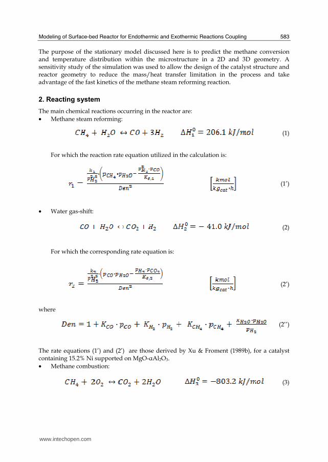
Modeling of Surface-bed Reactor for Endothermic and Exothermic Reactions Coupling
583
The purpose of the stationary model discussed here is to predict the methane conversion and temperature distribution within the microstructure in a 2D and 3D geometry A sensitivity study of the simulation was used to allow the design of the catalyst structure and reactor geometry to reduce the massheat transfer limitation in the process and take advantage of the fast kinetics of the methane steam reforming reaction
2 Reacting system
The main chemical reactions occurring in the reactor are bull Methane steam reforming
(1)
For which the reaction rate equation utilized in the calculation is
(1rsquo)
bull Water gas-shift
(2)
For which the corresponding rate equation is
(2rsquo)
where
(2rsquorsquo)
The rate equations (1rsquo) and (2rsquo) are those derived by Xu amp Froment (1989b) for a catalyst containing 152 Ni supported on MgO-αAl2O3 bull Methane combustion
(3)
wwwintechopencom
Recent Advances in Modelling and Simulation
584
For which the corresponding rate equation is
(3rsquo)
The rate equation (3rsquo) suggested in the literature (Zanfir amp Gavriilidis (2003)) is valid for a catalyst containing Pt supported on α-Al2O3
Table 2 Kinetic parameters for the reaction rate equations
Partial pressures of gases pi in equations (1rsquo) (2rsquo) and (2rdquo) were correlated to their own concentrations by the ideal gas law The values of pre-exponential factors and activation energies used in the Arrhenius expression for the kinetic constants ie kk = kk0 exp(-EakRT) in equations (1rsquo) (2rsquo) and (3rsquo) are reported in Table 2 with the relevant dimensions In the same Table the values of the pre-exponential factors and of the heats of adsorption taken from the literature (Perry amp Green 1997) and used in Vanrsquot Hoff expression ie Ki = Ki0 exp(-ΔHiRT) for the constants in equation (2rdquo) and the expressions of the equilibrium constants Ke1 and Ke2 in equations (1rsquo) and (2rsquo) are also shown
3 Reactor model
31 Physical description
A 2D scheme of the reactor model is shown in Figure 1 where the various parts are identified by numbers The system is symmetric with respect to the channel 5 centerline and then the parts 1 and 9 2 and 8 3 and 7 and 4 and 6 are identical pairs With reference to Figure 1 reforming gas goes through the central channel 5 while combustion gas through channels 1 and 9 Parts 3 and 7 represent metallic plates where the structured catalysts layers for combustion (2 and 8) and steam reforming (4 and 6) respectively lie It is not very different from modular reactors made of stackable plates suggested in the literature (Xu amp Froment (1989a) Loffler et al 2002) The main difference is that in this case the external boundaries 10 and 11 (in Figure 1) are surfaces with no slip gas velocity while in the recalled case they were symmetry surfaces
Pre-exponential factors kk0 Activation energy Eak (kJmol) k10 (kmol bar05(kgcat s)) 11736 times 1012 2401 k20 (kmol(kgcatsbar)) 1955 times 106 6713 k30 (s-1) 40 times 108 900 Pre-exponential factor Ki0 Heat of adsorption ΔHi (kJmol) KCO0 (barminus1) 823 times 10minus5 - 7065 KCH40 (barminus1) 665 times 10minus4 - 3828 KH2O0 - 177 times 105 8868 KH20 (barminus1) 612 times 10minus9 - 829 Equilibrium constants Ke1 = exp(minus26830T + 30114) (bar2) Ke2 = exp(4400T ndash 4036)
wwwintechopencom
Modeling of Surface-bed Reactor for Endothermic and Exothermic Reactions Coupling
585
Figure 1 Reactor scheme
With respect to conventional catalytic reactors where a bed of catalytic solid particles fills the reactor volume and the gas crosses the bed in the present case the catalytic solid particles are located on the lateral surfaces of the reactor thus forming a surface bed Actually in the case in the object the true reactor is the catalyst layers while the homogeneous portions of the reactor (channels) act merely as ducts
32 Model
A three-dimensional heterogeneous steady-state model was developed in order to describe velocity concentration and temperature distributions inside the surface-bed reactor system with structured catalysts The model consists of the material energy and momentum balances equations and contains the constitutive equations for physical chemistry properties of the reactants species and the kinetic expressions for the reactions as found from the literature and presented above The model assumes that a) the variations of density due to the change of gas composition and temperature are small so that incompressible Navier-Stokes motion equation applies b) on the combustion side only the methane total oxidation reaction to H2O and CO2 occurs c) on the reforming side only the methane steam reforming and the water gas shift reactions occur d) reactions occur only inside the catalyst layers where instead convective momentum is not present e) conductive heat transfer is the only transport phenomenon occurring inside the metallic plates f) as suggested in the literature (Hou amp Hughes (2001) Zanfir amp Gavriilidis (2003)) carbon formation and deposition due to side reactions can be neglected by using an excess of steam that is a minimum steammethane molar ratio of 17 f) body forces are neglected the reacting species being gaseous The velocity variation in the reactor takes into account the influence of temperature and composition changes so that the global mass balance is satisfied
(4)
Reactor performance were evaluated by the methane conversions calculated by integrating the local molar flow rates
(5)
wwwintechopencom
Recent Advances in Modelling and Simulation
586
According to Figure 1 for each catalyst layer and channel and for the metal sheets the due momentum energy and mass balances were set together with the proper boundary conditions in the rectangular coordinates (xndashyndashz) (Cartesian coordinates are indicated in Figure 1 and the z direction is perpendicular with respect to the scheme) with dependent variables velocity components pressure temperature (T) and species concentrations (ci) Equations vectorial formulation are reported in the following so they are valid for both 2D and 3D formulations
Combustion channels 1 and 9 and steam reforming channel 5 Momentum balance
(6)
(7)
Boundary conditions are bull specified velocity with normal component at the channel ingress
bull no slip at the channel boundaries in the y (2D and 3D) and z (3D) directions
bull specified pressure at the channel exit P = P0 With reference to Figure 1 for the momentum balance equations the boundaries of channels 1 and 9 are the external boundaries (10 and 11) of the reactor and the internal boundaries between the channels and the catalyst layers respectively while the boundaries of channel 5 are the internal boundaries between the channel and the catalyst layers Energy balance
(8)
Boundary conditions are bull specified temperature at the channel ingress
bull convective heat flux at the channel exit bull Channels 1 and 9 no heat flux through the channel external boundaries in the y (2D and
3D) and z (3D) directions ie and thermal continuity
at the internal boundaries (l gas
phase and catalyst phase)
bull Channel 5 thermal continuity at the
internal boundaries (l gas phase and catalyst phase) Mass balances
(9)
Boundary conditions are
bull specified concentrations at the channel ingress
bull continuity through the boundary between the gas phase and the catalyst layer ie where and
bull convective mass flux at the channel exit where i and j subscript refers to the ith and jth specie respectively
wwwintechopencom
Modeling of Surface-bed Reactor for Endothermic and Exothermic Reactions Coupling
587
Catalyst Layers 2 and 8 Energy balance
(10)
Boundary conditions are bull thermal continuity at the layers boundaries in the y directions (2D and 3D)
(l gas phase and catalyst phase)
bull thermal insulation at the layer boundaries in the x (2D and 3D) and z (3D) directions
Mass balances
(11)
being θi the stoichiometric coefficient of the ith specie Boundary conditions are bull continuity through the boundary between the layer and the gas phase
where and
and no mass flow between the layer and the metal sheets in the y (2D and 3D) direction
bull no mass flux through the layer boundaries in the x (2D and 3D) and z (3D) directions
Metal sheets 3 and 7 Energy balance
(12)
Boundary conditions are bull thermal insulation at the sheet boundaries in the x (2D and 3D) and z (3D) directions
bull thermal continuity on the sheet boundaries in the y direction (2D and 3D)
Catalyst Layers 4 and 6
Energy balance
(13)
Boundary conditions are bull thermal insulation at the layer boundaries in the x (2D and 3D) and z (3D) directions
bull thermal continuity on the layers boundaries in the y direction (2D and 3D)
Mass balances
(14)
being θji the stoichiometric coefficients of the i specie in the j reaction
wwwintechopencom
Recent Advances in Modelling and Simulation
588
Boundary conditions are bull continuity through the boundary between the layer and the gas phase
where and
and no mass flow
between the catalyst layer and the metal sheet in
the y (2D and 3D) direction bull no mass flux through the layer boundaries in the x (2D and 3D) and z (3D) directions
In the balances above the gas densities were calculated using the ideal gas law whereas for catalyst density a constant value was assumed Viscosities and thermal conductivities of the gaseous species refer to the values of the component largely in excess in the specific gas mixtures that is H2O for the steam reforming channel and air for the combustion channels Their dependence of the temperature was excerpted from experimental values from the literature (Perry amp Green (1997)) and included as interpolated functions inside the calculation software To work out heat capacities expressions such as
(15)
were used where A B and C were evaluated by the regression of an expression (Perry amp Green (1997) such as
(16)
The diffusivity coefficients were calculated for a binary mixture between component ith and H2O (in the reforming channel) or air (in the combustion channels) The effective diffusion coefficient inside the catalyst layer is (Perry amp Green (1997)
(17)
where is the catalyst porosity τ the tortuosity and Dij the Knudsen diffusion coefficient and the molecular diffusion coefficient of the ith specie in the jth specie respectively Molecular diffusion coefficients were evaluated using (Perry amp Green (1997))
(18)
where T is the temperature in [K] π the total pressure of the system in [Pa] Mi and Mj the molecular weights of ith and jth species respectively and φi the atomic diffusion volumes characteristic for each component (Perry amp Green (1997)) Knudsen diffusion coefficients were evaluated using (Perry amp Green (1997))
(19)
where Rp is the mean pore radius and T the temperature into the catalyst
wwwintechopencom
Modeling of Surface-bed Reactor for Endothermic and Exothermic Reactions Coupling
589
33 Numerical stuff and reference case simulation
The finite element solution algorithm was completed using COMSOL Multiphysics (Comsol Inc version 33a) Multiphysics modules of incompressible Navier-Stokes convectionndashdiffusion and conductionndashconvection were applied when appropriate to the three-phase domains Meshing parameters were different for the 2D and the 3D FEM schemes In particular in the case of 2D a mapped mesh scheme was employed with rectangular extra fine meshes and edge vertex distribution as follows longitudinal edges 1001 transverse edges 51 (metallic plate) and 101 (catalyst layers and channels) In the case of 3D predefined mesh sizes extra coarse with characteristics listed in Table 3 were employed
Number of degrees of freedom 381162
Number of mesh points 6976
Number of elements 33702
Tetrahedral 33702
Number of boundary elements 12840
Triangular 12840
Number of edge elements 740
Number of vertex elements 24
Minimum element quality 0158
Element volume ratio 0015
Table 3 Mesh Statistics
A reference case with given reactor geometric configuration and operating conditions was chosen to carry out a reference case simulation Other simulations were carried out to explore the influence on the reactor performance of specific geometrical andor operating parameter changes The conditions used in the calculations for the reference case are listed in Table 4 Inlet conditions for the reforming side are similar to those used by Xu and Froment (1989b) but for the total pressure close to atmospheric in our case 29 bar characteristic of industrial operation in the kinetics from Xu amp Froment This because as suggested in the literature (Kolios et al 2004) small-scale hydrogen production which is the potential application for such type of reactor is expected to operate at low pressure This represents a limit of the present work However similar detailed rate equations for the investigated reacting system are not available at ambient pressure in the literature Data reported in Table 4 show that the inlet reforming reaction mixture has a steammethane ratio of 3 and contains trace amounts of CO2 H2 and CO On the methane combustion side the airndashmethane mixture has a 40 air excess with respect to stoichiometric The inlet temperature of both streams is 800 K that is close to that typical of industrial steam reforming The inlet methane mass flow rate in the reforming channel is fixed at 167 cm3s at STP while the inlet methane mass flow rate in the combustion channel is obtained from an overall heat balance The data for reforming catalyst used in the calculations are typical for such a reaction and similar to that used by Xu amp Froment (1989a) for a catalyst containing 152 Ni supported on MgO-αAl2O3
wwwintechopencom
Recent Advances in Modelling and Simulation
590
Table 4 Data used for reference case calculations
Figure 2 Temperature space profiles along the reactor centerline of the reforming channel (solid blue) centerline of the combustion channel (solid red) centerline of the reforming catalyst (dashed blue) and centerline of the combustion catalyst (dashed red)
Gas phase Reforming channel Combustion channels Inlet conditions co-current flow compositions vol H2O 6666 CH4 3333 750 CO2 1 10-3 CO 1 10-3 O2 1943 N2 7307 H2 1 10-3 temperature 800 K 800 K CH4 mass flow rate cm3s (STP) 167 0417 pressure 101 kPa (channel outlet) 101 kPa (channel outlet) channel width m 2 10-3 1 10-3 channel height m 10 10-2 average velocity ms 097 087 channel length m 5 10-2 Catalyst layers thickness (c) μm 200 Average pore radius nm 15 porosity 05 tortuosity 4 Metal plates Thickness m 5 10-4 material aluchrom Thermal conductivity w(m K) Temperature dependent
wwwintechopencom
Modeling of Surface-bed Reactor for Endothermic and Exothermic Reactions Coupling
591
Figure 3 Axial profiles of heat flux in the y direction adjacent to the reforming catalyst in the metallic plate (solid line) in the reforming channel (dotted line)
The catalyst layer density is assumed to be 2300 kgm3 For both type of catalyst layers an average pore radius of 15 nm together with a porosity of 05 and a tortuosity factor of 4 are considered These values are typical for both combustion and reforming catalysts (De Deken et al 1982 Xu amp Froment 1989 b Groppi et al 1995)
4 Results
41 Thermal behaviour
Given the symmetry of the reactor for both 3D and 2D simulations only half of the reactor was simulated by substituting the proper boundary conditions (symmetry) in place of the lacking half Results in simulations performed with the 2D model under the reference case conditions are shown in Figures 2-7 The first aspect to consider is the thermal coupling of steam reforming with catalytic combustion in terms of evolution of both exothermic and endothermic conversion Figure 2 shows the temperature longitudinal profiles on the centerlines of the combustion and the reforming channels and in the combustion and reforming catalysts The profiles are very close each other and they increase from the inlet value of 800 to 914 K at the reactor outlet Therefore the catalytic combustion provides the necessary heat flux to heat up both reaction mixtures and to simultaneously drive the endothermic process A methane conversion at the reactor outlet of 089 for combustion and 074 for reforming are achieved Figure 3 shows the axial profiles of the absolute values of the heat fluxes in the y direction at the boundaries of the reforming catalyst One profile (solid line) is the heat flux from the metallic plate towards the reforming catalyst the other the heat flux from the reforming catalyst to the gas mixture in the reforming channel The two profiles present similar shapes with a maximum at 7 mm and 5 mm from the reactor entrance (distances within which the profiles are increasing) The difference between the profiles represents the heat absorbed by the reforming reaction system (eqs (1) and (2)) The maxima heat fluxes generated and consumed reach values of the order of 105 Wm2 ie 10 Wcm2 that considering the very small temperature gradients (Figure 2) is a very high value with respect to that attainable in industrial practice
wwwintechopencom
Recent Advances in Modelling and Simulation
592
a)
b)
Figure 4 Reactor temperature transverse profiles a at 15 cm from the reactor entrance b at 10 cm from the reactor outlet From 0 to 1 reforming channel From 1 to 12 reforming catalyst From 12 to 17 metallic plate From 17 to 19 combustion catalyst From 19 to 24 combustion channel
A further aspect to be examined is the magnitude of the transverse temperature gradients From Figure 2 it is already evident that the four profiles are very close each other However the transverse temperature gradients can be better analyzed from Figure 4 where the transverse temperature profiles at 15 cm (Figure 4a) from the reactor entrance and at 05 cm (Figure 4b) from the reactor outlet are shown In particular Figure 4a which pertains to the distance from the reactor inlet where the highest transverse temperature gradients develop evidences that the maximum temperature difference between reforming and combustion catalyst is 07 K while the maximum difference between the reforming and combustion channels is less than 10 K although that inside the reforming channel is almost 20 K Much lower differences can be observed close to the reactor outlet Specifically Figure 4b shows that the maximum temperature difference between reforming and combustion catalyst is 01 K that between the reforming and combustion channels is less than 1 K and that inside the reforming channel is almost 2 K As a result the high thermal conductivity of the metallic
wwwintechopencom
Modeling of Surface-bed Reactor for Endothermic and Exothermic Reactions Coupling
593
wall makes possible an efficient heat transfer at a temperature difference of the order of tenths of K With reference to Figure 4 it must be remarked that the value 0 of the transverse coordinate represents the centre of the reactor and the centre of the reforming channel Therefore at that point there is not a physical boundary the heat flux and the momentum flux are both zero and the x component of the gas velocity is maximum On the contrary the value 29 10-3 m of the transverse coordinate represents a solid wall that is the external boundary of the reactor and the boundary of the combustion channel This means that the heat flux is zero both components of the gas velocity are zero and the momentum flux is not zero This is one of the reasons because for the same distance in the transverse direction (y) the gas phase temperature difference in the reforming channel results always larger than that in the combustion channel (Figures 2 4a and 4b)
42 Mass transfer and chemical reactions
The concentration on the centerline of the reforming channel of the various species involved in the reactions occurring within the reforming catalyst are shown in Figure 5 This yields an overall picture of the reactor performance The hydrogen concentration steadily increases from the initial value to about 9 molm3 resulting the most abundant component in the exit gas mixture The ratio between the hydrogen concentration and CO concentration is very high (about 9)
Figure 5 Axial profiles of species concentrations on the centerline of the reforming channel
One important aspect to determine is the effect of interphase mass transport resistance Figure 6a shows the methane concentration axial profiles on the centerlines of the combustion channels and of the combustion catalyst while Figure 6b shows the correspondent profiles for the reforming section of the reactor From these Figures the differences between the channel and the catalyst profiles in each section yield a measure of the resistance to the interphase transport As expected in the combustion section the axial methane concentration profiles both in the channel and in the catalyst show an exponentially decreasing trend which reflects the relatively simple kinetics of the reaction In contrast a more complex trend is shown by the axial methane concentration profile in the catalyst because of the non linearity of the kinetics and the simultaneous occurrence of two
wwwintechopencom
Recent Advances in Modelling and Simulation
594
reactions (eqs (1) and (2)) Another aspect to examine is the size of the concentration gradients in the transverse direction These can be appreciated from Figure 7 where the transverse methane concentration profiles at 15 cm from the reactor inlet and at 05 cm from the reactor outlet are shown In particular the first profile which pertains to the distance from the reactor inlet where the highest transverse temperature gradients develops evidences that the gradients inside the reforming and the combustion channels are negligible with respect to the gradients in the catalyst phase The order of magnitude of these latter range from 105 molm4 close to the reactor inlet to 104 molm4 in the remaining part of the reforming catalyst and in all the combustion catalyst too
a)
b)
Figure 6 Axial methane concentration profiles along the reactor (a) solid line combustion channel dashed line combustion catalyst (b) solid line reforming channel dashed line reforming catalyst
wwwintechopencom
Modeling of Surface-bed Reactor for Endothermic and Exothermic Reactions Coupling
595
Figure 7 Methane concentration transverse profiles at 15 cm from the reactor entrance (solid line) and at 10 cm from the reactor outlet (dashed line) From 0 to 1 reforming channel From 1 to 12 reforming catalyst From 12 to 17 metallic plate From 17 to 19 combustion catalyst From 19 to 24 combustion channel
43 Methane concentration in the combustion channel
A basic requirement of the system in the object which is thought to be used for energy feeding of portable electric devices should be the complete reliability with respect to possible uncontrolled rises in temperature or even to a possible explosion hazard In this view the coordination between exothermic and endothermic reaction rates appears fundamental However even in the case such a coordination occurs the possible progress of the combustion reaction in the homogeneous phase may represent an hazard In addition if the concentration of the reacting mixture entering the combustion channel is within the flammability limits and the temperature becomes high enough it could ignite before the reactor inlet Therefore for safety purposes the occurrence of the exothermic reaction here represented by the methane combustion in the homogeneous phase should be avoided A possible way to make the system of hydrogen generation intrinsically safe is to feed the combustion mixture at a methane concentration below the LEL (lower explosivity limit) Considering that at STP the LEL of methane in air is about 5 vol that the autoignition temperature for airmethane mixtures is around 900 K the extimated LEL of methane in air at such a temperature should be about 3 vol (Crowl amp Louvar (2002)) Therefore a safe operating concentration should be about 3 vol To this purpose in this work beside those carried out under the conditions considered in the reference case other simulations were effected for which for a given methane mass flow rate its concentration at the combustion channel inlet was kept below 3 vol In this way the system is intrinsically safe because the reacting mixture cannot ignite spontaneously In addition the simulation becomes more realistic the contribution to the methane combustion of the homogeneous phase being really absent as implicitly hypothesized in this work
wwwintechopencom
Recent Advances in Modelling and Simulation
596
Figure 8 Temperature distribution over the boundaries of the 3D reactor
The comparison of results of runs performed under these conditions with those effected under the conditions of the reference case are reported in the following when analyzing the influence of various parameters on the reactor performance These simulations are labeled in the paper as n-expl in contrast to the others that are recalled as expl
44 Comparison between 2D and 3D results
For given operating conditions some simulations were carried out in both 2D and 3D geometry In principle a plane 2D geometry represents a slice of the reactor where the z dimension is greatly prevalent with respect to the y dimension Actually the model reactor has not such characteristics the length in the z dimension being 10 mm that is only 5 times the reforming channel width This means that the boundary effects due to the presence of the boundary walls in the z direction may have a significant influence on the velocity temperature and species concentration profiles that certainly influence the overall reactor performance Figures 8 shows the temperature distribution over the boundaries of the 3D reactor obtained under operating conditions of the reference case From this Figure the effect of the boundaries along the z direction appears evident
wwwintechopencom
Modeling of Surface-bed Reactor for Endothermic and Exothermic Reactions Coupling
597
Figure 9 Temperature space profiles along the reactor calculated with the 2D model (for the legend see caption to Figure 2)
Figure 10 Temperature space profiles along the reactor calculated with the 3D model (for the legend see caption to Figure 2)
Figures 9 and 10 show the reactor temperature longitudinal profiles on the centerlines of the combustion and the reforming channels and on the centerline of the combustion and reforming catalysts in the case of 2D and 3D geometry models respectively Both were calculated under the same operating conditions ie same inlet mass flow rates and compositions of the reference case (expl) but inlet temperature of 900 K In the case of the
wwwintechopencom
Recent Advances in Modelling and Simulation
598
3D simulation (Figure 10) the temperature profiles are those lying over a xy plane intersecting the reactor in the middle of its height along z The two sets of profiles appear quite similar the temperatures in the combustion section (catalyst and channel) are always slightly higher than the corresponding ones in the reforming section However a closer inspection reveals some significant differences In the 2D case the temperature after an initial slow growth increases steadily from 900 K at the reactor inlet up to 965 K at the reactor outlet while in the other case it grows faster reaches 960 K at 60 of the reactor length and remains constant up to the outlet Another difference is represented by the larger transverse temperature gradients of the 3D case with respect to 2D In the 2D case they are comparable with those observed in Figure 2 for the reference case while in the 3D case they are almost double This is true for all combinations ie catalyst-catalyst catalyst-channel and channel-channel On the whole the 3D case shows a faster progress of the reactions with consequent need for faster heat transfer These differences in the thermal behaviour between 2D and 3D simulations persist when the comparison is extended to other operating conditions and in addition they reflect the better overall performance of the 3D reactor with respect to the 2D as can be seen by the following discussion The quantitative comparison between the 2D and 3D simulations was made with respect to the main results ie the methane conversion in both the combustion and the steam reforming channels as obtained from equation 5 Further beside the methane conversions other parameters are employed ie a) the gas hourly space velocities GHSV in the combustion and steam reforming sides of the reactor calculated as ratio between gas flow rates at the reactor inlet temperature and volume of catalyst b) the maximum temperature reached in the reactor c) the mean gas residence time trm in both the combustion and the reforming channel calculated as ratio between the gas flow rates at the reactor inlet temperature and the volume of the channel and d) the hydrogen yield φH2 evaluated as ratio between the amounts of methane reacted and hydrogen produced GHSV and trm were useful to allow the comparison of simulations carried out by changing the catalyst volume or the channel width as discussed later Results of simulations carried out with the 2D and 3D models under various operating conditions are reported in Table 5 Those referring to the operating conditions of the reference case are listed in the first two rows of such a Table The other operating conditions are i) same inlet temperature of the reference case but different methane concentration in the combustion channel (3rd and 4th rows of Table 5) and ii) different inlet temperatures for the two conditions above (5th-8th rows of Table 5) Focusing the comparison on the results of the simulations in 2D and 3D with the same operating conditions it appears that in general the methane conversions at the reactor outlet calculated with the 2D geometry in both the combustion and reforming channels are lower than the correspondent in 3D geometry but in one case (Xch4-sr 3rd and 4th rows of the Table) This finding reflects the differences in the thermal behaviour discussed above In any case such conversions differ by less than 10 but in the last two rows of the Table where the differences are larger It is worth noting however that even in this case the values of the conversions are congruent with the overall results of the simulation For instance the lower value of Xch4-co in the 2D with respect to the correspondent in 3D results in a lower value of Xch4-sr and in a lower maximum temperature reached in the reactor
wwwintechopencom
Modeling of Surface-bed Reactor for Endothermic and Exothermic Reactions Coupling
599
Geometry Tin K
Xch4-co Xch4-sr Tmax K Trm-co ms
Trm-sr ms
GHSVco h-1
GHSVsr h-1
φH2
2D expl 800 089 074 914 0057 0026 314840 702884 329
3D expl 800 096 077 914 0057 0026 314840 702884 333
2D n-expl 800 036 045 827 0020 0026 900588 702884 344
3D n-expl 800 040 041 828 0020 0026 900588 702884 356
2D expl 900 095 090 965 0051 0023 354194 790745 305
3D expl 900 099 093 960 0051 0023 354194 790745 300
2D n-expl 900 049 069 900 0018 0023 1013162 790745 322
3D n-expl 900 068 079 920 0018 0023 1013162 790745 318
Table 5 Comparison of 2D and 3D results obtained under the same operating conditions
For what concerns the hydrogen yield focusing again the comparison on the results of the simulations in 2D and 3D at the same operating conditions data show that φH2rsquos obtained with the 2D geometry model are lower than that in 3D model but in one case (7th and 8th row of Table 5) It is worth noting that φH2=3 would be the stoichiometric value if reaction (1) were the only occurring in the reforming catalyst so that the amount exceeding 3 is due to the contribution of reaction (2) Data in Table 5 also shows the influence on the reactor performance of temperature and inlet methane concentration in the combustion channel In the case of inlet temperature of 900 K and methane concentration within the explosivity limits (case referring to results in Figures 9 and 10) the methane conversion is practically 1 (3D model) for the combustion reaction and very high for the reforming reactions However under these conditions the hydrogen yield is the lowest In contrast when the highest hydrogen yield is reached the lowest methane conversion is achieved Similar considerations can be done for the other results in the Table so that a general trend can be drawn from such results The higher the maximum temperature reached in the reactor the higher the methane conversions and the lower the hydrogen yield
45 Influence of the channels width
The reactor thermal behaviour and performance was studied for different channels width Wc at constant inlet flow rates of the reaction mixtures Runs were also carried out by keeping constant the mean inlet velocities of reaction mixtures The variation range for the combustion channels width Wc-co was 1-15 mm and for the reforming channel width Wc-sr 2-3 mm All other parameters were kept at their reference case values Keeping constant the inlet mass flow rates and altering the channel width results in modifying the inlet velocities in the reactor and consequently the mean residence time (trm) of the gases in the channels but the GHSVrsquos do not change The results in terms of methane conversions in the combustion and reforming channels are reported in Table 6 for the reference cases (3rd and 4th row in Table) and for cases where the methane concentration in the combustion channels were below the LEL (1st and 2nd row) At constant mass flow rates the influence of the channel width or better of trm appears negligible under n-expl conditions with a slight
wwwintechopencom
Recent Advances in Modelling and Simulation
600
prevalence of the reactor with narrower channels and weak under expl conditions with in contrast better performance for the reactor with wider channels Therefore it is not possible to draw conclusions
Wc-sr mm
Tin K
Xch4 -
co Xch4-sr
Tmax K
trm-co ms
trm-sr ms
GHSVco h-1
GHSVsr h-1
2 n-expl 800 036 045 827 0020 0026 900588 702884
3 n-expl 800 034 044 819 0030 0038 900588 702884
2 expl 800 089 074 914 0057 0026 314840 702884
3 expl 800 092 081 940 0086 0038 314840 702884
Vcost- 3 n-expl 800 022 033 800 0020 0026 1350882 1054327
Table 6 Comparison between reactor performance as a function of channel width
Unlike the previous case where inlet flow rates were kept constant an increase in channel width keeping the mean gas velocity and the value of trm constants affects significantly the outlet conversions In this case the amount of reactants flowing through the reactor per unit catalyst volume and then GHSV increases (compare 1st and 5th rows in Table 5) Increasing channel widths from their reference case value (Wc-sr = 2 mm and Wc-co= 1) at constant gas inlet velocity leads to methane conversion reduction because a) the catalyst amount becomes insufficient for the amount of reactants fed in the reactor and b) the external mass transfer resistances play a stronger role The overall reaction heat fluxes remain the same as channel width increases leaving a similar amount of sensible heat to be used for heating up larger amounts of reactants This results in lower temperatures along the reactor
46 Influence of catalyst thickness
The influence of catalyst thickness c on the reactor behaviour was studied by keeping constant the reactants mass flow rates The reactor operation was simulated for three values of catalyst thickness ie 200 100 and 50 microm while keeping all the other parameters at their reference case values but for what concerns the inlet methane concentration in the combustion channel that was at non explosive level This with respect to the reference case corresponds to decreasing GHSV of factors 2 and 4 respectively Changes in the catalyst thickness influence considerably both thermal behaviour and outlet conversions As above the comparison is made through the methane conversions achieved in the two cases both in the steam reforming and in the combustion channels The results are reported in Table 7 It is evident that the loss of performance due to a decrease of 50 of c from 200 to 100 μm is almost negligible This is mainly due to the conservative parameters used for defining the catalyst layer characteristics (ie mean pore radius and tortuosity) that results in a very impervious path for diffusing gases However when c is further decreased methane conversion both in the combustion and in the reforming section significantly decrease The hydrogen yield does not change too much within the limits of the three cases analyzed
wwwintechopencom
Modeling of Surface-bed Reactor for Endothermic and Exothermic Reactions Coupling
601
δc μm
Tin K Xch4 -co Xch4-sr Tmax Ktrm-co ms
trm-sr ms
GHSVco h-1
GHSVsr h-1
φH2
200 n-expl 800 036 045 827 0020 0026 900588 702884 344
100 n-expl 800 035 045 827 0020 0026 1801176 1405768 344
50 n-expl 800 027 038 800 0020 0026 3602352 2811536 342
Table 7 Comparison between reactor performance as a function of catalyst thickness
5 Discussion
As seen in the previous section (4) there are several operating parameters that influence the performances of the system They are typical of reacting systems and can be summarized as GHSVrsquos tmrrsquos and inlet gas temperatures The particularity of the present case is the simultaneous occurrence of two coupled reactions one exothermic and the other endothermic in which the extent of the second depends on the extent (heat produced) of the first and the effectiveness of the heat transferred In addition the coupling of the two reactions does not exclude to have for each set of values of the mentioned parameters pertaining to one reaction several sets of parameters for the other reaction This makes the system quite complex and difficult to analyze However some general considerations can be drawn
Figure 11 Methane conversions in the combustion and reforming sides of the reactor as a function of GHSV for various operating conditions available in Table 6 and 7
The first is that as expected GHVS plays a key role in determining the reactor performances although this is supported by only a part of the data For instance data in Table 7 pertaining to simulations of the influence of such a parameter carried out by changing GHSV in the same way for both sections of the reacting system shows a clear effect of GHSV the reactor
0 1000000 2000000 3000000 4000000
GHSV h-1
02
04
06
08
1
XC
H4
-co a
nd
XC
H4
-sr -
data from Table 7 comb side
data from Table 7 refor side
data from Table 6 comb side
data from Table 6 refor side
wwwintechopencom
Recent Advances in Modelling and Simulation
602
performance decreases as GHSV increases on both sides of the reactor Such an influence does not appear strong the conversion change being about 20 against GHSV variations of a factor 4 (Figure 11) The influence of GHSV is more evident from data in Table 6 pertaining to simulations of the influence of tmr In fact also in this case a clear trend appears and the influence even though in the same direction of the previous case appears much stronger since with respect to a GHSV change of about 20 the methane conversion varies by a factor 4 (Figure 11) Such a strong influence is due to the combined effect of tmr especially on the combustion side of the reactor (cfr Table 6) Instead for data in Table 5 pertaining to simulations of the reliability of 2D and 3D models and the effect of gas inlet temperature it is not possible to highlight a clear influence The comparison between the results obtained with the 2D and 3D models under the same operating conditions have evidenced differences in the performance of the reactor not large but significant When we move from 2D to 3D models such differences result in an increase from 5 to 20 of both Xch4-co and Xch4-sr which reflects a different thermal behavior of the reacting system and influence also the hydrogen yield It is worth noting that the computation time required in the two cases is very different Specifically using an HP xw8400workstation equipped with 2 Xeon processors and 4 GB of RAM a 2D simulation takes on the average about 20 minutes with respect to 50-60 hours necessary in the 3D case It is impossible by now to establish which is the more correct or the more reliable In particular it should be assessed if 2D simulations are suitable for purpose of reactor design and experimental data interpretation The answer should come from the comparison of the results of such simulations with experimental data obtained with a real reactor geometrically comparable operated under conditions as much as similar to those fixed for the simulations This represents argument for coming work of the authors Further interesting aspects to be studied are the simulation of unsteady-state conditions and specifically of the system start-up and of the system response to small changes in the gas feeding flow rates and temperatures
6 Conclusions
Methane steam reforming coupled with methane catalytic combustion by means of indirect heat transfer in a surface-bed catalytic reactor was studied by 2D and 3D models The reactor consists of a central reforming channel and two lateral combustion channels A reference case for what concerns operating conditions and reactor geometry was chosen and its simulation was carried out Changes of reactor performance as consequence of operating parameters and reactor geometry variations were analyzed with respect to the reference case The simulation showed that suitable amount of fuel and adequate catalyst activity in the combustion channel can provide enough heat to simultaneously heat up the reaction mixture and drive the endothermic process The proximity between the heat source and the heat sink increases the efficiency of heat transfer resulting in transverse temperature gradients do not exceeding generally 07 K across the metallic wall and 20 K across the gas in the channel Decrease of transverse temperature differences and intraphase mass transfer resistances have the global effect of reducing the reactor dimension and the catalyst amount The influence of channels width and catalyst layer thickness on reactor behaviour was also studied At constant inlet flow rates changes of channel width in the range 1ndash2 mm do not introduce significant differences in the reactor performance Rather small differences in the
wwwintechopencom
Modeling of Surface-bed Reactor for Endothermic and Exothermic Reactions Coupling
603
catalyst axial temperature profiles and outlet methane conversions are observed In contrast altering the channel width at constant inlet velocities has strong influence Larger channel width results in lower conversion and smoother axial temperature profiles Intraphase resistances are present even for catalyst thickness of micrometers for both reforming and combustion processes Increasing GHSV that is the inlet flow ratecatalyst volume ratio leads to lower outlet conversions Due to different effect of catalyst layer thickness on reforming and combustion channels there are significant changes in the reactor temperature profile Results indicate that steam reforming of methane in a surface-bed reactor is feasible provided that mass flow rates channels width catalyst loadings and thickness are properly designed
7 Notation
cp specific heat J(mol K) c concentration molm3 Deff effective diffusion coefficient m2s D molecular diffusion coefficient m2s GHSV gas hourly space velocity h-1 k thermal conductivity W(m K) or reaction rate constant Ke equilibrium constant M molecular weight kgmol LEL lower explosivity limit vol
unit vector perpendicular to the flux surface
N molar flux at the boundary mol(m2 s) p partial pressure bar P total pressure bar q thermal flux at the boundary J(m2 s) r reaction rate various dimensions (see eqs 1rsquo 2rsquo and 3rsquo) Rp catalyst pore radius nm STP standard temperature and pressure (298 K and 101 103 Pa) t time s T temperature K ts transverse surface ux Velocity component on the x coordinate
velocity vector
v normal component of velocity at the channel ingress x axial coordinate m X conversion y transverse coordinate m Wc distance between the reactor plates m z vertical coordinate m Greek letters ΔH0r heat of reaction at reference state conditions KJmol c catalyst thickness μm catalyst porosity φ atomic diffusion volume or chemical reaction yield
wwwintechopencom
Recent Advances in Modelling and Simulation
604
θ stoichiometric coefficient ρ density kgm3 τ catalyst tortuosity
Subscripts and superscripts cat catalyst co combustion CH4 methane H2 hydrogen in inlet i chemical species j channel k reaction l phase rm mean residence s metal sheet sr steam reforming 0 channel ingress 1 reforming reaction 2 water gas shift reaction 3 combustion reaction
8 Acknowledgements
The authors gratefully acknowledge the financial support of MIUR under grant PRIN ndeg 2006094333004
9 References
Akers WW amp Camp DP (1955) Kinetics of the methanendashsteam reaction AIChE Journal Vol 1 471ndash475 ISSN0001-1541
Allen DW Gerhard ER amp Likins Jr MR (1975) Kinetics of the MethanendashSteam Reaction Ind Eng Chem Proc Des Dev Vol 14 No 3 256-259 ISSN0196-4305
Aparicio L (1997) Transient Isotopic Studies and Microkinetic Modeling of Methane Reforming over Nickel Catalysts Journal of Catal Vol 165 No 2 262-274 ISSN 0021-9517
Avci AK Trimm DL amp İlsen Oumlnsan Z (2001) Heterogeneous reactor modeling for simulation of catalytic oxidation and steam reforming of methane Chem Eng Sci Vol 56 No 2 641-649 ISSN0009-2509
Bridger GW (1980) The steam reforming of hydrocarbons Catalysis Vol 3 39-69 ISSN0140-0568
Cao C Wang Y amp Rozmiarek RT (2005) Heterogeneous reactor model for steam reforming of methane in a microchannel reactor with microstructured catalysts Catal Today Vol 110 No 1-2 92ndash97 ISSN 0920-5861
Craciun R Shereck B amp Gorte RJ (1998) Kinetic studies of methane steam reforming on ceria-supported Pd Catal Lett Vol 51 No 3ndash4 149-153 ISSN 1011-372x
wwwintechopencom
Modeling of Surface-bed Reactor for Endothermic and Exothermic Reactions Coupling
605
Crowl DA amp Louvar JF (2002) Chemical Process Safety fundamentals with applications 2nd ed Prentice Hall PTR Upper Saddle River NJ USA ISBN 0-13mdash018176-5
De Deken J C Devos E F amp Froment G F (1982) Steam reforming of natural gas Intrinsic kinetics diffusional influences and reactor design ACS Symposium Series 196 181ndash197 ISSN0097-6156
Ehrfeld W amp Hessel V Lowe H (2000) Microreactor Wiley-VCH Verlag GmbH D-69469 ISBN Weinheim Germany
Gosiewski K (2001) Simulations of non-stationary reactors for catalytic conversion of methane to synthesis gas Chem Eng Sci Vol 56 No 4 1501-1510 ISSN
Groppi G Belloli A Tronconi E Forzatti P (1995) A comparison of lumped and distributed models of monolith catalytic combustors Chem Eng Sci Vol 50 No 17 2705ndash2715 ISSN0009-2509
Holladay JD Wang Y amp Jones E (2004) Review of Developments in Portable Hydrogen Production Using Microreactor Technology Chem Rev Vol 104 No 10 4767-4790 ISSN 0009-2665
Hou K amp Hughes R (2001) The kinetics of methane steam reforming over a Ni-Al2O3 catalyst Chem Eng Journal Vol 82 No 1-3 311-328 ISSN 1385-8947
Jamal Y amp Wyszynski M L (1994) On-board generation of hydrogen-rich gaseous fuels a review Int J of Hydrogen Energy Vol 19 No 7 557-572 ISSN 0360-3199
Jensen KF (2001) Microreaction engineering is small better Chem Eng Sci Vol 56 No 2 293-303 ISSN0009-2509
Kolios G Gritsch A Glo1ckler B amp Sorescu G (2004) Novel Reactor Concepts for Thermally Efficient Methane Steam Reforming Modeling and Simulation Ind Eng Chem Res Vol 43 No 16 4796-4808 ISSN0888-5885
Kruger P Blakeley J amp Leaver J (2003) Potential in New Zealand for use of hydrogen as a transportation fuel Int J of Hydrogen Energy Vol 28 No 8 795ndash802 ISSN 0360-3199
Kvamsdal HM Svendsen HF Hertzberg T amp Olsvik O (1999) Dynamic simulation and optimization of a catalytic steam reformer Chem Eng Sci Vol 54 No 13-14 2697-2706 ISSN0009-2509
Lerer M Duic N Alves LM amp Carvalho MG (2006) H2 RES energy planning tool for increasing the penetration of renewable energy sources in island energy supply In New and Renewable Technologies for Sustanaible Development MG Carvalho and NH Afgan (Ed s) 15-30 World Scientific ISBN 10 981-270-505-8 Singapore
Lerou JJ amp Ng KM (1996) Chemical reaction engineering A multiscale approach to a multiobjective task Chem Eng Sci Vol 51 No 10 1595-1614 ISSN0009-2509
Lincoln SF (2006) Challenged Earth ch7 Imperial College Press ISBN 1-86094-526-0 London
Loffler D G Faz C F Sokolovskii V amp Iglesia E (2002) Catalytic separator plate reactor and method of catalytic reforming of fuel to Hydrogen PCT Int Appl WO 0228769 A2
Luna C amp Becerra AM (1997) Kinetics of methane steam reforming on a Ni on alumina-titania catalyst React Kinet Catal Lett Vol 61 No 2 369-374 ISSN 0133-1736
Marschner F Renner HJ amp Boll W (2005) Electronic Encyclopedia Release 2005 7th ed in Ullmannrsquos Encyclopedia of Industrial Chemistry M Bohnet et al (Eds) Vol a12 John Wiley amp Sons ISBN-13 978-3-527-30385-4
wwwintechopencom
Recent Advances in Modelling and Simulation
606
Moore R B amp Raman V (1998) Hydrogen infrastructure for fuel cell transportation Int J of Hydrogen Energy Vol 23 No 7 617-620 ISSN 0360-3199
Perry RH amp Green DW (1999) Perrys Chemical Engineers Handbook (7th Ed) McGraw-Hill ISBN 0-07-049841-5
Robbins F A Zhu H amp Jackson GS (2003) Transient modeling of combined catalytic combustionCH4 steam reformng Catal Today Vol 83 No 1-4 141ndash156 ISSN 0920-5861
Rostrup-Nielsen JR Christiansen LJ amp BakHansen JH (1988) Activity of steam reforming catalysts Role and assessment Appl Catal Vol 43 No 2 287-303 ISSN0166-9834
Rostrup-Nielsen JR (1995) Innovation and the catalytic process industry - the science and challenge Chem Eng Sci Vol 50 No 24 4061-4071 ISSN0009-2509
Rostrup-Nielsen JR Dybkjaer I amp Coulthard GRG (2001) Topical Conf Proc AIChE Spring National Meeting Houston TX April Paper No 1
Rostrup-Nielsen JR (2004) Fuels and Energy for the Future The Role of Catalysis Catal Rev - Science and Engineering Vol 46 No 3ndash4 247-270 ISSN0161-4940
Schubert K Brandner J Fichtner M Linder G Schyhulla U amp Wenka A (2001) Microstructure devices for applications in thermal and chemical process engineering Microscale Thermophys Eng Vol 5 No 1 17-39 ISSN1089-3954
Tronconi E amp Groppi G (2000) A study on the thermal behavior of structured plate-type catalysts with metallic supports for gassolid exothermic reactions Chem Eng Sci Vol 55 Issue 24 December 6021-6036 ISSN0009-2509
Wang Y Johnson BR Cao C Chin Y Rozmiarek RT Gao Y Tonkovich AL (2005) Engineered catalysts for microchannel reactor applications In Microreactor Technology and Process Intensification Y Wang J Holladay (Eds) 65-73 ACS Symposium Series Vol 914 ISBN-13 9780841239234
Xu J amp Froment GF (1989a) Methane steam reforming II Diffusional limitations and reactor simulation AIChE Journal Vol 35 No 1 97-103 ISSN0001-1541
Xu J amp Froment GF (1989b) Methane steam reforming methanation and water-gas shift I Intrinsic kinetics AIChE Journal Vol 35 No 1 88-96 ISSN0001-1541
Zanfir M amp Gavriilidis A (2003) Catalytic Combustion Assisted Methane Steam Reforming Chem Eng Sci Vol 58 No 17 3947ndash 3960 ISSN0009-2509
wwwintechopencom
Modelling and SimulationEdited by Giuseppe Petrone and Giuliano Cammarata
ISBN 978-3-902613-25-7Hard cover 688 pagesPublisher I-Tech Education and PublishingPublished online 01 June 2008Published in print edition June 2008
InTech EuropeUniversity Campus STeP Ri Slavka Krautzeka 83A 51000 Rijeka Croatia Phone +385 (51) 770 447 Fax +385 (51) 686 166wwwintechopencom
InTech ChinaUnit 405 Office Block Hotel Equatorial Shanghai No65 Yan An Road (West) Shanghai 200040 China
Phone +86-21-62489820 Fax +86-21-62489821
This book collects original and innovative research studies concerning modeling and simulation of physicalsystems in a very wide range of applications encompassing micro-electro-mechanical systems measurementinstrumentations catalytic reactors biomechanical applications biological and chemical sensorsmagnetosensitive materials silicon photonic devices electronic devices optical fibers electro-microfluidicsystems composite materials fuel cells indoor air-conditioning systems active magnetic levitation systemsand more Some of the most recent numerical techniques as well as some of the software among the mostaccurate and sophisticated in treating complex systems are applied in order to exhaustively contribute inknowledge advances
How to referenceIn order to correctly reference this scholarly work feel free to copy and paste the following
Salvatore Vaccaro and Paolo Ciambelli (2008) Modeling of Surface-bed Reactor for Endothermic andExothermic Reactions Coupling Modelling and Simulation Giuseppe Petrone and Giuliano Cammarata (Ed)ISBN 978-3-902613-25-7 InTech Available fromhttpwwwintechopencombooksmodelling_and_simulationmodeling_of_surface-bed_reactor_for_endothermic_and_exothermic_reactions_coupling
copy 2008 The Author(s) Licensee IntechOpen This chapter is distributedunder the terms of the Creative Commons Attribution-NonCommercial-ShareAlike-30 License which permits use distribution and reproduction fornon-commercial purposes provided the original is properly cited andderivative works building on this content are distributed under the samelicense
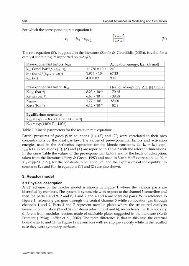
Recent Advances in Modelling and Simulation
584
For which the corresponding rate equation is
(3rsquo)
The rate equation (3rsquo) suggested in the literature (Zanfir amp Gavriilidis (2003)) is valid for a catalyst containing Pt supported on α-Al2O3
Table 2 Kinetic parameters for the reaction rate equations
Partial pressures of gases pi in equations (1rsquo) (2rsquo) and (2rdquo) were correlated to their own concentrations by the ideal gas law The values of pre-exponential factors and activation energies used in the Arrhenius expression for the kinetic constants ie kk = kk0 exp(-EakRT) in equations (1rsquo) (2rsquo) and (3rsquo) are reported in Table 2 with the relevant dimensions In the same Table the values of the pre-exponential factors and of the heats of adsorption taken from the literature (Perry amp Green 1997) and used in Vanrsquot Hoff expression ie Ki = Ki0 exp(-ΔHiRT) for the constants in equation (2rdquo) and the expressions of the equilibrium constants Ke1 and Ke2 in equations (1rsquo) and (2rsquo) are also shown
3 Reactor model
31 Physical description
A 2D scheme of the reactor model is shown in Figure 1 where the various parts are identified by numbers The system is symmetric with respect to the channel 5 centerline and then the parts 1 and 9 2 and 8 3 and 7 and 4 and 6 are identical pairs With reference to Figure 1 reforming gas goes through the central channel 5 while combustion gas through channels 1 and 9 Parts 3 and 7 represent metallic plates where the structured catalysts layers for combustion (2 and 8) and steam reforming (4 and 6) respectively lie It is not very different from modular reactors made of stackable plates suggested in the literature (Xu amp Froment (1989a) Loffler et al 2002) The main difference is that in this case the external boundaries 10 and 11 (in Figure 1) are surfaces with no slip gas velocity while in the recalled case they were symmetry surfaces
Pre-exponential factors kk0 Activation energy Eak (kJmol) k10 (kmol bar05(kgcat s)) 11736 times 1012 2401 k20 (kmol(kgcatsbar)) 1955 times 106 6713 k30 (s-1) 40 times 108 900 Pre-exponential factor Ki0 Heat of adsorption ΔHi (kJmol) KCO0 (barminus1) 823 times 10minus5 - 7065 KCH40 (barminus1) 665 times 10minus4 - 3828 KH2O0 - 177 times 105 8868 KH20 (barminus1) 612 times 10minus9 - 829 Equilibrium constants Ke1 = exp(minus26830T + 30114) (bar2) Ke2 = exp(4400T ndash 4036)
wwwintechopencom
Modeling of Surface-bed Reactor for Endothermic and Exothermic Reactions Coupling
585
Figure 1 Reactor scheme
With respect to conventional catalytic reactors where a bed of catalytic solid particles fills the reactor volume and the gas crosses the bed in the present case the catalytic solid particles are located on the lateral surfaces of the reactor thus forming a surface bed Actually in the case in the object the true reactor is the catalyst layers while the homogeneous portions of the reactor (channels) act merely as ducts
32 Model
A three-dimensional heterogeneous steady-state model was developed in order to describe velocity concentration and temperature distributions inside the surface-bed reactor system with structured catalysts The model consists of the material energy and momentum balances equations and contains the constitutive equations for physical chemistry properties of the reactants species and the kinetic expressions for the reactions as found from the literature and presented above The model assumes that a) the variations of density due to the change of gas composition and temperature are small so that incompressible Navier-Stokes motion equation applies b) on the combustion side only the methane total oxidation reaction to H2O and CO2 occurs c) on the reforming side only the methane steam reforming and the water gas shift reactions occur d) reactions occur only inside the catalyst layers where instead convective momentum is not present e) conductive heat transfer is the only transport phenomenon occurring inside the metallic plates f) as suggested in the literature (Hou amp Hughes (2001) Zanfir amp Gavriilidis (2003)) carbon formation and deposition due to side reactions can be neglected by using an excess of steam that is a minimum steammethane molar ratio of 17 f) body forces are neglected the reacting species being gaseous The velocity variation in the reactor takes into account the influence of temperature and composition changes so that the global mass balance is satisfied
(4)
Reactor performance were evaluated by the methane conversions calculated by integrating the local molar flow rates
(5)
wwwintechopencom
Recent Advances in Modelling and Simulation
586
According to Figure 1 for each catalyst layer and channel and for the metal sheets the due momentum energy and mass balances were set together with the proper boundary conditions in the rectangular coordinates (xndashyndashz) (Cartesian coordinates are indicated in Figure 1 and the z direction is perpendicular with respect to the scheme) with dependent variables velocity components pressure temperature (T) and species concentrations (ci) Equations vectorial formulation are reported in the following so they are valid for both 2D and 3D formulations
Combustion channels 1 and 9 and steam reforming channel 5 Momentum balance
(6)
(7)
Boundary conditions are bull specified velocity with normal component at the channel ingress
bull no slip at the channel boundaries in the y (2D and 3D) and z (3D) directions
bull specified pressure at the channel exit P = P0 With reference to Figure 1 for the momentum balance equations the boundaries of channels 1 and 9 are the external boundaries (10 and 11) of the reactor and the internal boundaries between the channels and the catalyst layers respectively while the boundaries of channel 5 are the internal boundaries between the channel and the catalyst layers Energy balance
(8)
Boundary conditions are bull specified temperature at the channel ingress
bull convective heat flux at the channel exit bull Channels 1 and 9 no heat flux through the channel external boundaries in the y (2D and
3D) and z (3D) directions ie and thermal continuity
at the internal boundaries (l gas
phase and catalyst phase)
bull Channel 5 thermal continuity at the
internal boundaries (l gas phase and catalyst phase) Mass balances
(9)
Boundary conditions are
bull specified concentrations at the channel ingress
bull continuity through the boundary between the gas phase and the catalyst layer ie where and
bull convective mass flux at the channel exit where i and j subscript refers to the ith and jth specie respectively
wwwintechopencom
Modeling of Surface-bed Reactor for Endothermic and Exothermic Reactions Coupling
587
Catalyst Layers 2 and 8 Energy balance
(10)
Boundary conditions are bull thermal continuity at the layers boundaries in the y directions (2D and 3D)
(l gas phase and catalyst phase)
bull thermal insulation at the layer boundaries in the x (2D and 3D) and z (3D) directions
Mass balances
(11)
being θi the stoichiometric coefficient of the ith specie Boundary conditions are bull continuity through the boundary between the layer and the gas phase
where and
and no mass flow between the layer and the metal sheets in the y (2D and 3D) direction
bull no mass flux through the layer boundaries in the x (2D and 3D) and z (3D) directions
Metal sheets 3 and 7 Energy balance
(12)
Boundary conditions are bull thermal insulation at the sheet boundaries in the x (2D and 3D) and z (3D) directions
bull thermal continuity on the sheet boundaries in the y direction (2D and 3D)
Catalyst Layers 4 and 6
Energy balance
(13)
Boundary conditions are bull thermal insulation at the layer boundaries in the x (2D and 3D) and z (3D) directions
bull thermal continuity on the layers boundaries in the y direction (2D and 3D)
Mass balances
(14)
being θji the stoichiometric coefficients of the i specie in the j reaction
wwwintechopencom
Recent Advances in Modelling and Simulation
588
Boundary conditions are bull continuity through the boundary between the layer and the gas phase
where and
and no mass flow
between the catalyst layer and the metal sheet in
the y (2D and 3D) direction bull no mass flux through the layer boundaries in the x (2D and 3D) and z (3D) directions
In the balances above the gas densities were calculated using the ideal gas law whereas for catalyst density a constant value was assumed Viscosities and thermal conductivities of the gaseous species refer to the values of the component largely in excess in the specific gas mixtures that is H2O for the steam reforming channel and air for the combustion channels Their dependence of the temperature was excerpted from experimental values from the literature (Perry amp Green (1997)) and included as interpolated functions inside the calculation software To work out heat capacities expressions such as
(15)
were used where A B and C were evaluated by the regression of an expression (Perry amp Green (1997) such as
(16)
The diffusivity coefficients were calculated for a binary mixture between component ith and H2O (in the reforming channel) or air (in the combustion channels) The effective diffusion coefficient inside the catalyst layer is (Perry amp Green (1997)
(17)
where is the catalyst porosity τ the tortuosity and Dij the Knudsen diffusion coefficient and the molecular diffusion coefficient of the ith specie in the jth specie respectively Molecular diffusion coefficients were evaluated using (Perry amp Green (1997))
(18)
where T is the temperature in [K] π the total pressure of the system in [Pa] Mi and Mj the molecular weights of ith and jth species respectively and φi the atomic diffusion volumes characteristic for each component (Perry amp Green (1997)) Knudsen diffusion coefficients were evaluated using (Perry amp Green (1997))
(19)
where Rp is the mean pore radius and T the temperature into the catalyst
wwwintechopencom
Modeling of Surface-bed Reactor for Endothermic and Exothermic Reactions Coupling
589
33 Numerical stuff and reference case simulation
The finite element solution algorithm was completed using COMSOL Multiphysics (Comsol Inc version 33a) Multiphysics modules of incompressible Navier-Stokes convectionndashdiffusion and conductionndashconvection were applied when appropriate to the three-phase domains Meshing parameters were different for the 2D and the 3D FEM schemes In particular in the case of 2D a mapped mesh scheme was employed with rectangular extra fine meshes and edge vertex distribution as follows longitudinal edges 1001 transverse edges 51 (metallic plate) and 101 (catalyst layers and channels) In the case of 3D predefined mesh sizes extra coarse with characteristics listed in Table 3 were employed
Number of degrees of freedom 381162
Number of mesh points 6976
Number of elements 33702
Tetrahedral 33702
Number of boundary elements 12840
Triangular 12840
Number of edge elements 740
Number of vertex elements 24
Minimum element quality 0158
Element volume ratio 0015
Table 3 Mesh Statistics
A reference case with given reactor geometric configuration and operating conditions was chosen to carry out a reference case simulation Other simulations were carried out to explore the influence on the reactor performance of specific geometrical andor operating parameter changes The conditions used in the calculations for the reference case are listed in Table 4 Inlet conditions for the reforming side are similar to those used by Xu and Froment (1989b) but for the total pressure close to atmospheric in our case 29 bar characteristic of industrial operation in the kinetics from Xu amp Froment This because as suggested in the literature (Kolios et al 2004) small-scale hydrogen production which is the potential application for such type of reactor is expected to operate at low pressure This represents a limit of the present work However similar detailed rate equations for the investigated reacting system are not available at ambient pressure in the literature Data reported in Table 4 show that the inlet reforming reaction mixture has a steammethane ratio of 3 and contains trace amounts of CO2 H2 and CO On the methane combustion side the airndashmethane mixture has a 40 air excess with respect to stoichiometric The inlet temperature of both streams is 800 K that is close to that typical of industrial steam reforming The inlet methane mass flow rate in the reforming channel is fixed at 167 cm3s at STP while the inlet methane mass flow rate in the combustion channel is obtained from an overall heat balance The data for reforming catalyst used in the calculations are typical for such a reaction and similar to that used by Xu amp Froment (1989a) for a catalyst containing 152 Ni supported on MgO-αAl2O3
wwwintechopencom
Recent Advances in Modelling and Simulation
590
Table 4 Data used for reference case calculations
Figure 2 Temperature space profiles along the reactor centerline of the reforming channel (solid blue) centerline of the combustion channel (solid red) centerline of the reforming catalyst (dashed blue) and centerline of the combustion catalyst (dashed red)
Gas phase Reforming channel Combustion channels Inlet conditions co-current flow compositions vol H2O 6666 CH4 3333 750 CO2 1 10-3 CO 1 10-3 O2 1943 N2 7307 H2 1 10-3 temperature 800 K 800 K CH4 mass flow rate cm3s (STP) 167 0417 pressure 101 kPa (channel outlet) 101 kPa (channel outlet) channel width m 2 10-3 1 10-3 channel height m 10 10-2 average velocity ms 097 087 channel length m 5 10-2 Catalyst layers thickness (c) μm 200 Average pore radius nm 15 porosity 05 tortuosity 4 Metal plates Thickness m 5 10-4 material aluchrom Thermal conductivity w(m K) Temperature dependent
wwwintechopencom
Modeling of Surface-bed Reactor for Endothermic and Exothermic Reactions Coupling
591
Figure 3 Axial profiles of heat flux in the y direction adjacent to the reforming catalyst in the metallic plate (solid line) in the reforming channel (dotted line)
The catalyst layer density is assumed to be 2300 kgm3 For both type of catalyst layers an average pore radius of 15 nm together with a porosity of 05 and a tortuosity factor of 4 are considered These values are typical for both combustion and reforming catalysts (De Deken et al 1982 Xu amp Froment 1989 b Groppi et al 1995)
4 Results
41 Thermal behaviour
Given the symmetry of the reactor for both 3D and 2D simulations only half of the reactor was simulated by substituting the proper boundary conditions (symmetry) in place of the lacking half Results in simulations performed with the 2D model under the reference case conditions are shown in Figures 2-7 The first aspect to consider is the thermal coupling of steam reforming with catalytic combustion in terms of evolution of both exothermic and endothermic conversion Figure 2 shows the temperature longitudinal profiles on the centerlines of the combustion and the reforming channels and in the combustion and reforming catalysts The profiles are very close each other and they increase from the inlet value of 800 to 914 K at the reactor outlet Therefore the catalytic combustion provides the necessary heat flux to heat up both reaction mixtures and to simultaneously drive the endothermic process A methane conversion at the reactor outlet of 089 for combustion and 074 for reforming are achieved Figure 3 shows the axial profiles of the absolute values of the heat fluxes in the y direction at the boundaries of the reforming catalyst One profile (solid line) is the heat flux from the metallic plate towards the reforming catalyst the other the heat flux from the reforming catalyst to the gas mixture in the reforming channel The two profiles present similar shapes with a maximum at 7 mm and 5 mm from the reactor entrance (distances within which the profiles are increasing) The difference between the profiles represents the heat absorbed by the reforming reaction system (eqs (1) and (2)) The maxima heat fluxes generated and consumed reach values of the order of 105 Wm2 ie 10 Wcm2 that considering the very small temperature gradients (Figure 2) is a very high value with respect to that attainable in industrial practice
wwwintechopencom
Recent Advances in Modelling and Simulation
592
a)
b)
Figure 4 Reactor temperature transverse profiles a at 15 cm from the reactor entrance b at 10 cm from the reactor outlet From 0 to 1 reforming channel From 1 to 12 reforming catalyst From 12 to 17 metallic plate From 17 to 19 combustion catalyst From 19 to 24 combustion channel
A further aspect to be examined is the magnitude of the transverse temperature gradients From Figure 2 it is already evident that the four profiles are very close each other However the transverse temperature gradients can be better analyzed from Figure 4 where the transverse temperature profiles at 15 cm (Figure 4a) from the reactor entrance and at 05 cm (Figure 4b) from the reactor outlet are shown In particular Figure 4a which pertains to the distance from the reactor inlet where the highest transverse temperature gradients develop evidences that the maximum temperature difference between reforming and combustion catalyst is 07 K while the maximum difference between the reforming and combustion channels is less than 10 K although that inside the reforming channel is almost 20 K Much lower differences can be observed close to the reactor outlet Specifically Figure 4b shows that the maximum temperature difference between reforming and combustion catalyst is 01 K that between the reforming and combustion channels is less than 1 K and that inside the reforming channel is almost 2 K As a result the high thermal conductivity of the metallic
wwwintechopencom
Modeling of Surface-bed Reactor for Endothermic and Exothermic Reactions Coupling
593
wall makes possible an efficient heat transfer at a temperature difference of the order of tenths of K With reference to Figure 4 it must be remarked that the value 0 of the transverse coordinate represents the centre of the reactor and the centre of the reforming channel Therefore at that point there is not a physical boundary the heat flux and the momentum flux are both zero and the x component of the gas velocity is maximum On the contrary the value 29 10-3 m of the transverse coordinate represents a solid wall that is the external boundary of the reactor and the boundary of the combustion channel This means that the heat flux is zero both components of the gas velocity are zero and the momentum flux is not zero This is one of the reasons because for the same distance in the transverse direction (y) the gas phase temperature difference in the reforming channel results always larger than that in the combustion channel (Figures 2 4a and 4b)
42 Mass transfer and chemical reactions
The concentration on the centerline of the reforming channel of the various species involved in the reactions occurring within the reforming catalyst are shown in Figure 5 This yields an overall picture of the reactor performance The hydrogen concentration steadily increases from the initial value to about 9 molm3 resulting the most abundant component in the exit gas mixture The ratio between the hydrogen concentration and CO concentration is very high (about 9)
Figure 5 Axial profiles of species concentrations on the centerline of the reforming channel
One important aspect to determine is the effect of interphase mass transport resistance Figure 6a shows the methane concentration axial profiles on the centerlines of the combustion channels and of the combustion catalyst while Figure 6b shows the correspondent profiles for the reforming section of the reactor From these Figures the differences between the channel and the catalyst profiles in each section yield a measure of the resistance to the interphase transport As expected in the combustion section the axial methane concentration profiles both in the channel and in the catalyst show an exponentially decreasing trend which reflects the relatively simple kinetics of the reaction In contrast a more complex trend is shown by the axial methane concentration profile in the catalyst because of the non linearity of the kinetics and the simultaneous occurrence of two
wwwintechopencom
Recent Advances in Modelling and Simulation
594
reactions (eqs (1) and (2)) Another aspect to examine is the size of the concentration gradients in the transverse direction These can be appreciated from Figure 7 where the transverse methane concentration profiles at 15 cm from the reactor inlet and at 05 cm from the reactor outlet are shown In particular the first profile which pertains to the distance from the reactor inlet where the highest transverse temperature gradients develops evidences that the gradients inside the reforming and the combustion channels are negligible with respect to the gradients in the catalyst phase The order of magnitude of these latter range from 105 molm4 close to the reactor inlet to 104 molm4 in the remaining part of the reforming catalyst and in all the combustion catalyst too
a)
b)
Figure 6 Axial methane concentration profiles along the reactor (a) solid line combustion channel dashed line combustion catalyst (b) solid line reforming channel dashed line reforming catalyst
wwwintechopencom
Modeling of Surface-bed Reactor for Endothermic and Exothermic Reactions Coupling
595
Figure 7 Methane concentration transverse profiles at 15 cm from the reactor entrance (solid line) and at 10 cm from the reactor outlet (dashed line) From 0 to 1 reforming channel From 1 to 12 reforming catalyst From 12 to 17 metallic plate From 17 to 19 combustion catalyst From 19 to 24 combustion channel
43 Methane concentration in the combustion channel
A basic requirement of the system in the object which is thought to be used for energy feeding of portable electric devices should be the complete reliability with respect to possible uncontrolled rises in temperature or even to a possible explosion hazard In this view the coordination between exothermic and endothermic reaction rates appears fundamental However even in the case such a coordination occurs the possible progress of the combustion reaction in the homogeneous phase may represent an hazard In addition if the concentration of the reacting mixture entering the combustion channel is within the flammability limits and the temperature becomes high enough it could ignite before the reactor inlet Therefore for safety purposes the occurrence of the exothermic reaction here represented by the methane combustion in the homogeneous phase should be avoided A possible way to make the system of hydrogen generation intrinsically safe is to feed the combustion mixture at a methane concentration below the LEL (lower explosivity limit) Considering that at STP the LEL of methane in air is about 5 vol that the autoignition temperature for airmethane mixtures is around 900 K the extimated LEL of methane in air at such a temperature should be about 3 vol (Crowl amp Louvar (2002)) Therefore a safe operating concentration should be about 3 vol To this purpose in this work beside those carried out under the conditions considered in the reference case other simulations were effected for which for a given methane mass flow rate its concentration at the combustion channel inlet was kept below 3 vol In this way the system is intrinsically safe because the reacting mixture cannot ignite spontaneously In addition the simulation becomes more realistic the contribution to the methane combustion of the homogeneous phase being really absent as implicitly hypothesized in this work
wwwintechopencom
Recent Advances in Modelling and Simulation
596
Figure 8 Temperature distribution over the boundaries of the 3D reactor
The comparison of results of runs performed under these conditions with those effected under the conditions of the reference case are reported in the following when analyzing the influence of various parameters on the reactor performance These simulations are labeled in the paper as n-expl in contrast to the others that are recalled as expl
44 Comparison between 2D and 3D results
For given operating conditions some simulations were carried out in both 2D and 3D geometry In principle a plane 2D geometry represents a slice of the reactor where the z dimension is greatly prevalent with respect to the y dimension Actually the model reactor has not such characteristics the length in the z dimension being 10 mm that is only 5 times the reforming channel width This means that the boundary effects due to the presence of the boundary walls in the z direction may have a significant influence on the velocity temperature and species concentration profiles that certainly influence the overall reactor performance Figures 8 shows the temperature distribution over the boundaries of the 3D reactor obtained under operating conditions of the reference case From this Figure the effect of the boundaries along the z direction appears evident
wwwintechopencom
Modeling of Surface-bed Reactor for Endothermic and Exothermic Reactions Coupling
597
Figure 9 Temperature space profiles along the reactor calculated with the 2D model (for the legend see caption to Figure 2)
Figure 10 Temperature space profiles along the reactor calculated with the 3D model (for the legend see caption to Figure 2)
Figures 9 and 10 show the reactor temperature longitudinal profiles on the centerlines of the combustion and the reforming channels and on the centerline of the combustion and reforming catalysts in the case of 2D and 3D geometry models respectively Both were calculated under the same operating conditions ie same inlet mass flow rates and compositions of the reference case (expl) but inlet temperature of 900 K In the case of the
wwwintechopencom
Recent Advances in Modelling and Simulation
598
3D simulation (Figure 10) the temperature profiles are those lying over a xy plane intersecting the reactor in the middle of its height along z The two sets of profiles appear quite similar the temperatures in the combustion section (catalyst and channel) are always slightly higher than the corresponding ones in the reforming section However a closer inspection reveals some significant differences In the 2D case the temperature after an initial slow growth increases steadily from 900 K at the reactor inlet up to 965 K at the reactor outlet while in the other case it grows faster reaches 960 K at 60 of the reactor length and remains constant up to the outlet Another difference is represented by the larger transverse temperature gradients of the 3D case with respect to 2D In the 2D case they are comparable with those observed in Figure 2 for the reference case while in the 3D case they are almost double This is true for all combinations ie catalyst-catalyst catalyst-channel and channel-channel On the whole the 3D case shows a faster progress of the reactions with consequent need for faster heat transfer These differences in the thermal behaviour between 2D and 3D simulations persist when the comparison is extended to other operating conditions and in addition they reflect the better overall performance of the 3D reactor with respect to the 2D as can be seen by the following discussion The quantitative comparison between the 2D and 3D simulations was made with respect to the main results ie the methane conversion in both the combustion and the steam reforming channels as obtained from equation 5 Further beside the methane conversions other parameters are employed ie a) the gas hourly space velocities GHSV in the combustion and steam reforming sides of the reactor calculated as ratio between gas flow rates at the reactor inlet temperature and volume of catalyst b) the maximum temperature reached in the reactor c) the mean gas residence time trm in both the combustion and the reforming channel calculated as ratio between the gas flow rates at the reactor inlet temperature and the volume of the channel and d) the hydrogen yield φH2 evaluated as ratio between the amounts of methane reacted and hydrogen produced GHSV and trm were useful to allow the comparison of simulations carried out by changing the catalyst volume or the channel width as discussed later Results of simulations carried out with the 2D and 3D models under various operating conditions are reported in Table 5 Those referring to the operating conditions of the reference case are listed in the first two rows of such a Table The other operating conditions are i) same inlet temperature of the reference case but different methane concentration in the combustion channel (3rd and 4th rows of Table 5) and ii) different inlet temperatures for the two conditions above (5th-8th rows of Table 5) Focusing the comparison on the results of the simulations in 2D and 3D with the same operating conditions it appears that in general the methane conversions at the reactor outlet calculated with the 2D geometry in both the combustion and reforming channels are lower than the correspondent in 3D geometry but in one case (Xch4-sr 3rd and 4th rows of the Table) This finding reflects the differences in the thermal behaviour discussed above In any case such conversions differ by less than 10 but in the last two rows of the Table where the differences are larger It is worth noting however that even in this case the values of the conversions are congruent with the overall results of the simulation For instance the lower value of Xch4-co in the 2D with respect to the correspondent in 3D results in a lower value of Xch4-sr and in a lower maximum temperature reached in the reactor
wwwintechopencom
Modeling of Surface-bed Reactor for Endothermic and Exothermic Reactions Coupling
599
Geometry Tin K
Xch4-co Xch4-sr Tmax K Trm-co ms
Trm-sr ms
GHSVco h-1
GHSVsr h-1
φH2
2D expl 800 089 074 914 0057 0026 314840 702884 329
3D expl 800 096 077 914 0057 0026 314840 702884 333
2D n-expl 800 036 045 827 0020 0026 900588 702884 344
3D n-expl 800 040 041 828 0020 0026 900588 702884 356
2D expl 900 095 090 965 0051 0023 354194 790745 305
3D expl 900 099 093 960 0051 0023 354194 790745 300
2D n-expl 900 049 069 900 0018 0023 1013162 790745 322
3D n-expl 900 068 079 920 0018 0023 1013162 790745 318
Table 5 Comparison of 2D and 3D results obtained under the same operating conditions
For what concerns the hydrogen yield focusing again the comparison on the results of the simulations in 2D and 3D at the same operating conditions data show that φH2rsquos obtained with the 2D geometry model are lower than that in 3D model but in one case (7th and 8th row of Table 5) It is worth noting that φH2=3 would be the stoichiometric value if reaction (1) were the only occurring in the reforming catalyst so that the amount exceeding 3 is due to the contribution of reaction (2) Data in Table 5 also shows the influence on the reactor performance of temperature and inlet methane concentration in the combustion channel In the case of inlet temperature of 900 K and methane concentration within the explosivity limits (case referring to results in Figures 9 and 10) the methane conversion is practically 1 (3D model) for the combustion reaction and very high for the reforming reactions However under these conditions the hydrogen yield is the lowest In contrast when the highest hydrogen yield is reached the lowest methane conversion is achieved Similar considerations can be done for the other results in the Table so that a general trend can be drawn from such results The higher the maximum temperature reached in the reactor the higher the methane conversions and the lower the hydrogen yield
45 Influence of the channels width
The reactor thermal behaviour and performance was studied for different channels width Wc at constant inlet flow rates of the reaction mixtures Runs were also carried out by keeping constant the mean inlet velocities of reaction mixtures The variation range for the combustion channels width Wc-co was 1-15 mm and for the reforming channel width Wc-sr 2-3 mm All other parameters were kept at their reference case values Keeping constant the inlet mass flow rates and altering the channel width results in modifying the inlet velocities in the reactor and consequently the mean residence time (trm) of the gases in the channels but the GHSVrsquos do not change The results in terms of methane conversions in the combustion and reforming channels are reported in Table 6 for the reference cases (3rd and 4th row in Table) and for cases where the methane concentration in the combustion channels were below the LEL (1st and 2nd row) At constant mass flow rates the influence of the channel width or better of trm appears negligible under n-expl conditions with a slight
wwwintechopencom
Recent Advances in Modelling and Simulation
600
prevalence of the reactor with narrower channels and weak under expl conditions with in contrast better performance for the reactor with wider channels Therefore it is not possible to draw conclusions
Wc-sr mm
Tin K
Xch4 -
co Xch4-sr
Tmax K
trm-co ms
trm-sr ms
GHSVco h-1
GHSVsr h-1
2 n-expl 800 036 045 827 0020 0026 900588 702884
3 n-expl 800 034 044 819 0030 0038 900588 702884
2 expl 800 089 074 914 0057 0026 314840 702884
3 expl 800 092 081 940 0086 0038 314840 702884
Vcost- 3 n-expl 800 022 033 800 0020 0026 1350882 1054327
Table 6 Comparison between reactor performance as a function of channel width
Unlike the previous case where inlet flow rates were kept constant an increase in channel width keeping the mean gas velocity and the value of trm constants affects significantly the outlet conversions In this case the amount of reactants flowing through the reactor per unit catalyst volume and then GHSV increases (compare 1st and 5th rows in Table 5) Increasing channel widths from their reference case value (Wc-sr = 2 mm and Wc-co= 1) at constant gas inlet velocity leads to methane conversion reduction because a) the catalyst amount becomes insufficient for the amount of reactants fed in the reactor and b) the external mass transfer resistances play a stronger role The overall reaction heat fluxes remain the same as channel width increases leaving a similar amount of sensible heat to be used for heating up larger amounts of reactants This results in lower temperatures along the reactor
46 Influence of catalyst thickness
The influence of catalyst thickness c on the reactor behaviour was studied by keeping constant the reactants mass flow rates The reactor operation was simulated for three values of catalyst thickness ie 200 100 and 50 microm while keeping all the other parameters at their reference case values but for what concerns the inlet methane concentration in the combustion channel that was at non explosive level This with respect to the reference case corresponds to decreasing GHSV of factors 2 and 4 respectively Changes in the catalyst thickness influence considerably both thermal behaviour and outlet conversions As above the comparison is made through the methane conversions achieved in the two cases both in the steam reforming and in the combustion channels The results are reported in Table 7 It is evident that the loss of performance due to a decrease of 50 of c from 200 to 100 μm is almost negligible This is mainly due to the conservative parameters used for defining the catalyst layer characteristics (ie mean pore radius and tortuosity) that results in a very impervious path for diffusing gases However when c is further decreased methane conversion both in the combustion and in the reforming section significantly decrease The hydrogen yield does not change too much within the limits of the three cases analyzed
wwwintechopencom
Modeling of Surface-bed Reactor for Endothermic and Exothermic Reactions Coupling
601
δc μm
Tin K Xch4 -co Xch4-sr Tmax Ktrm-co ms
trm-sr ms
GHSVco h-1
GHSVsr h-1
φH2
200 n-expl 800 036 045 827 0020 0026 900588 702884 344
100 n-expl 800 035 045 827 0020 0026 1801176 1405768 344
50 n-expl 800 027 038 800 0020 0026 3602352 2811536 342
Table 7 Comparison between reactor performance as a function of catalyst thickness
5 Discussion
As seen in the previous section (4) there are several operating parameters that influence the performances of the system They are typical of reacting systems and can be summarized as GHSVrsquos tmrrsquos and inlet gas temperatures The particularity of the present case is the simultaneous occurrence of two coupled reactions one exothermic and the other endothermic in which the extent of the second depends on the extent (heat produced) of the first and the effectiveness of the heat transferred In addition the coupling of the two reactions does not exclude to have for each set of values of the mentioned parameters pertaining to one reaction several sets of parameters for the other reaction This makes the system quite complex and difficult to analyze However some general considerations can be drawn
Figure 11 Methane conversions in the combustion and reforming sides of the reactor as a function of GHSV for various operating conditions available in Table 6 and 7
The first is that as expected GHVS plays a key role in determining the reactor performances although this is supported by only a part of the data For instance data in Table 7 pertaining to simulations of the influence of such a parameter carried out by changing GHSV in the same way for both sections of the reacting system shows a clear effect of GHSV the reactor
0 1000000 2000000 3000000 4000000
GHSV h-1
02
04
06
08
1
XC
H4
-co a
nd
XC
H4
-sr -
data from Table 7 comb side
data from Table 7 refor side
data from Table 6 comb side
data from Table 6 refor side
wwwintechopencom
Recent Advances in Modelling and Simulation
602
performance decreases as GHSV increases on both sides of the reactor Such an influence does not appear strong the conversion change being about 20 against GHSV variations of a factor 4 (Figure 11) The influence of GHSV is more evident from data in Table 6 pertaining to simulations of the influence of tmr In fact also in this case a clear trend appears and the influence even though in the same direction of the previous case appears much stronger since with respect to a GHSV change of about 20 the methane conversion varies by a factor 4 (Figure 11) Such a strong influence is due to the combined effect of tmr especially on the combustion side of the reactor (cfr Table 6) Instead for data in Table 5 pertaining to simulations of the reliability of 2D and 3D models and the effect of gas inlet temperature it is not possible to highlight a clear influence The comparison between the results obtained with the 2D and 3D models under the same operating conditions have evidenced differences in the performance of the reactor not large but significant When we move from 2D to 3D models such differences result in an increase from 5 to 20 of both Xch4-co and Xch4-sr which reflects a different thermal behavior of the reacting system and influence also the hydrogen yield It is worth noting that the computation time required in the two cases is very different Specifically using an HP xw8400workstation equipped with 2 Xeon processors and 4 GB of RAM a 2D simulation takes on the average about 20 minutes with respect to 50-60 hours necessary in the 3D case It is impossible by now to establish which is the more correct or the more reliable In particular it should be assessed if 2D simulations are suitable for purpose of reactor design and experimental data interpretation The answer should come from the comparison of the results of such simulations with experimental data obtained with a real reactor geometrically comparable operated under conditions as much as similar to those fixed for the simulations This represents argument for coming work of the authors Further interesting aspects to be studied are the simulation of unsteady-state conditions and specifically of the system start-up and of the system response to small changes in the gas feeding flow rates and temperatures
6 Conclusions
Methane steam reforming coupled with methane catalytic combustion by means of indirect heat transfer in a surface-bed catalytic reactor was studied by 2D and 3D models The reactor consists of a central reforming channel and two lateral combustion channels A reference case for what concerns operating conditions and reactor geometry was chosen and its simulation was carried out Changes of reactor performance as consequence of operating parameters and reactor geometry variations were analyzed with respect to the reference case The simulation showed that suitable amount of fuel and adequate catalyst activity in the combustion channel can provide enough heat to simultaneously heat up the reaction mixture and drive the endothermic process The proximity between the heat source and the heat sink increases the efficiency of heat transfer resulting in transverse temperature gradients do not exceeding generally 07 K across the metallic wall and 20 K across the gas in the channel Decrease of transverse temperature differences and intraphase mass transfer resistances have the global effect of reducing the reactor dimension and the catalyst amount The influence of channels width and catalyst layer thickness on reactor behaviour was also studied At constant inlet flow rates changes of channel width in the range 1ndash2 mm do not introduce significant differences in the reactor performance Rather small differences in the
wwwintechopencom
Modeling of Surface-bed Reactor for Endothermic and Exothermic Reactions Coupling
603
catalyst axial temperature profiles and outlet methane conversions are observed In contrast altering the channel width at constant inlet velocities has strong influence Larger channel width results in lower conversion and smoother axial temperature profiles Intraphase resistances are present even for catalyst thickness of micrometers for both reforming and combustion processes Increasing GHSV that is the inlet flow ratecatalyst volume ratio leads to lower outlet conversions Due to different effect of catalyst layer thickness on reforming and combustion channels there are significant changes in the reactor temperature profile Results indicate that steam reforming of methane in a surface-bed reactor is feasible provided that mass flow rates channels width catalyst loadings and thickness are properly designed
7 Notation
cp specific heat J(mol K) c concentration molm3 Deff effective diffusion coefficient m2s D molecular diffusion coefficient m2s GHSV gas hourly space velocity h-1 k thermal conductivity W(m K) or reaction rate constant Ke equilibrium constant M molecular weight kgmol LEL lower explosivity limit vol
unit vector perpendicular to the flux surface
N molar flux at the boundary mol(m2 s) p partial pressure bar P total pressure bar q thermal flux at the boundary J(m2 s) r reaction rate various dimensions (see eqs 1rsquo 2rsquo and 3rsquo) Rp catalyst pore radius nm STP standard temperature and pressure (298 K and 101 103 Pa) t time s T temperature K ts transverse surface ux Velocity component on the x coordinate
velocity vector
v normal component of velocity at the channel ingress x axial coordinate m X conversion y transverse coordinate m Wc distance between the reactor plates m z vertical coordinate m Greek letters ΔH0r heat of reaction at reference state conditions KJmol c catalyst thickness μm catalyst porosity φ atomic diffusion volume or chemical reaction yield
wwwintechopencom
Recent Advances in Modelling and Simulation
604
θ stoichiometric coefficient ρ density kgm3 τ catalyst tortuosity
Subscripts and superscripts cat catalyst co combustion CH4 methane H2 hydrogen in inlet i chemical species j channel k reaction l phase rm mean residence s metal sheet sr steam reforming 0 channel ingress 1 reforming reaction 2 water gas shift reaction 3 combustion reaction
8 Acknowledgements
The authors gratefully acknowledge the financial support of MIUR under grant PRIN ndeg 2006094333004
9 References
Akers WW amp Camp DP (1955) Kinetics of the methanendashsteam reaction AIChE Journal Vol 1 471ndash475 ISSN0001-1541
Allen DW Gerhard ER amp Likins Jr MR (1975) Kinetics of the MethanendashSteam Reaction Ind Eng Chem Proc Des Dev Vol 14 No 3 256-259 ISSN0196-4305
Aparicio L (1997) Transient Isotopic Studies and Microkinetic Modeling of Methane Reforming over Nickel Catalysts Journal of Catal Vol 165 No 2 262-274 ISSN 0021-9517
Avci AK Trimm DL amp İlsen Oumlnsan Z (2001) Heterogeneous reactor modeling for simulation of catalytic oxidation and steam reforming of methane Chem Eng Sci Vol 56 No 2 641-649 ISSN0009-2509
Bridger GW (1980) The steam reforming of hydrocarbons Catalysis Vol 3 39-69 ISSN0140-0568
Cao C Wang Y amp Rozmiarek RT (2005) Heterogeneous reactor model for steam reforming of methane in a microchannel reactor with microstructured catalysts Catal Today Vol 110 No 1-2 92ndash97 ISSN 0920-5861
Craciun R Shereck B amp Gorte RJ (1998) Kinetic studies of methane steam reforming on ceria-supported Pd Catal Lett Vol 51 No 3ndash4 149-153 ISSN 1011-372x
wwwintechopencom
Modeling of Surface-bed Reactor for Endothermic and Exothermic Reactions Coupling
605
Crowl DA amp Louvar JF (2002) Chemical Process Safety fundamentals with applications 2nd ed Prentice Hall PTR Upper Saddle River NJ USA ISBN 0-13mdash018176-5
De Deken J C Devos E F amp Froment G F (1982) Steam reforming of natural gas Intrinsic kinetics diffusional influences and reactor design ACS Symposium Series 196 181ndash197 ISSN0097-6156
Ehrfeld W amp Hessel V Lowe H (2000) Microreactor Wiley-VCH Verlag GmbH D-69469 ISBN Weinheim Germany
Gosiewski K (2001) Simulations of non-stationary reactors for catalytic conversion of methane to synthesis gas Chem Eng Sci Vol 56 No 4 1501-1510 ISSN
Groppi G Belloli A Tronconi E Forzatti P (1995) A comparison of lumped and distributed models of monolith catalytic combustors Chem Eng Sci Vol 50 No 17 2705ndash2715 ISSN0009-2509
Holladay JD Wang Y amp Jones E (2004) Review of Developments in Portable Hydrogen Production Using Microreactor Technology Chem Rev Vol 104 No 10 4767-4790 ISSN 0009-2665
Hou K amp Hughes R (2001) The kinetics of methane steam reforming over a Ni-Al2O3 catalyst Chem Eng Journal Vol 82 No 1-3 311-328 ISSN 1385-8947
Jamal Y amp Wyszynski M L (1994) On-board generation of hydrogen-rich gaseous fuels a review Int J of Hydrogen Energy Vol 19 No 7 557-572 ISSN 0360-3199
Jensen KF (2001) Microreaction engineering is small better Chem Eng Sci Vol 56 No 2 293-303 ISSN0009-2509
Kolios G Gritsch A Glo1ckler B amp Sorescu G (2004) Novel Reactor Concepts for Thermally Efficient Methane Steam Reforming Modeling and Simulation Ind Eng Chem Res Vol 43 No 16 4796-4808 ISSN0888-5885
Kruger P Blakeley J amp Leaver J (2003) Potential in New Zealand for use of hydrogen as a transportation fuel Int J of Hydrogen Energy Vol 28 No 8 795ndash802 ISSN 0360-3199
Kvamsdal HM Svendsen HF Hertzberg T amp Olsvik O (1999) Dynamic simulation and optimization of a catalytic steam reformer Chem Eng Sci Vol 54 No 13-14 2697-2706 ISSN0009-2509
Lerer M Duic N Alves LM amp Carvalho MG (2006) H2 RES energy planning tool for increasing the penetration of renewable energy sources in island energy supply In New and Renewable Technologies for Sustanaible Development MG Carvalho and NH Afgan (Ed s) 15-30 World Scientific ISBN 10 981-270-505-8 Singapore
Lerou JJ amp Ng KM (1996) Chemical reaction engineering A multiscale approach to a multiobjective task Chem Eng Sci Vol 51 No 10 1595-1614 ISSN0009-2509
Lincoln SF (2006) Challenged Earth ch7 Imperial College Press ISBN 1-86094-526-0 London
Loffler D G Faz C F Sokolovskii V amp Iglesia E (2002) Catalytic separator plate reactor and method of catalytic reforming of fuel to Hydrogen PCT Int Appl WO 0228769 A2
Luna C amp Becerra AM (1997) Kinetics of methane steam reforming on a Ni on alumina-titania catalyst React Kinet Catal Lett Vol 61 No 2 369-374 ISSN 0133-1736
Marschner F Renner HJ amp Boll W (2005) Electronic Encyclopedia Release 2005 7th ed in Ullmannrsquos Encyclopedia of Industrial Chemistry M Bohnet et al (Eds) Vol a12 John Wiley amp Sons ISBN-13 978-3-527-30385-4
wwwintechopencom
Recent Advances in Modelling and Simulation
606
Moore R B amp Raman V (1998) Hydrogen infrastructure for fuel cell transportation Int J of Hydrogen Energy Vol 23 No 7 617-620 ISSN 0360-3199
Perry RH amp Green DW (1999) Perrys Chemical Engineers Handbook (7th Ed) McGraw-Hill ISBN 0-07-049841-5
Robbins F A Zhu H amp Jackson GS (2003) Transient modeling of combined catalytic combustionCH4 steam reformng Catal Today Vol 83 No 1-4 141ndash156 ISSN 0920-5861
Rostrup-Nielsen JR Christiansen LJ amp BakHansen JH (1988) Activity of steam reforming catalysts Role and assessment Appl Catal Vol 43 No 2 287-303 ISSN0166-9834
Rostrup-Nielsen JR (1995) Innovation and the catalytic process industry - the science and challenge Chem Eng Sci Vol 50 No 24 4061-4071 ISSN0009-2509
Rostrup-Nielsen JR Dybkjaer I amp Coulthard GRG (2001) Topical Conf Proc AIChE Spring National Meeting Houston TX April Paper No 1
Rostrup-Nielsen JR (2004) Fuels and Energy for the Future The Role of Catalysis Catal Rev - Science and Engineering Vol 46 No 3ndash4 247-270 ISSN0161-4940
Schubert K Brandner J Fichtner M Linder G Schyhulla U amp Wenka A (2001) Microstructure devices for applications in thermal and chemical process engineering Microscale Thermophys Eng Vol 5 No 1 17-39 ISSN1089-3954
Tronconi E amp Groppi G (2000) A study on the thermal behavior of structured plate-type catalysts with metallic supports for gassolid exothermic reactions Chem Eng Sci Vol 55 Issue 24 December 6021-6036 ISSN0009-2509
Wang Y Johnson BR Cao C Chin Y Rozmiarek RT Gao Y Tonkovich AL (2005) Engineered catalysts for microchannel reactor applications In Microreactor Technology and Process Intensification Y Wang J Holladay (Eds) 65-73 ACS Symposium Series Vol 914 ISBN-13 9780841239234
Xu J amp Froment GF (1989a) Methane steam reforming II Diffusional limitations and reactor simulation AIChE Journal Vol 35 No 1 97-103 ISSN0001-1541
Xu J amp Froment GF (1989b) Methane steam reforming methanation and water-gas shift I Intrinsic kinetics AIChE Journal Vol 35 No 1 88-96 ISSN0001-1541
Zanfir M amp Gavriilidis A (2003) Catalytic Combustion Assisted Methane Steam Reforming Chem Eng Sci Vol 58 No 17 3947ndash 3960 ISSN0009-2509
wwwintechopencom
Modelling and SimulationEdited by Giuseppe Petrone and Giuliano Cammarata
ISBN 978-3-902613-25-7Hard cover 688 pagesPublisher I-Tech Education and PublishingPublished online 01 June 2008Published in print edition June 2008
InTech EuropeUniversity Campus STeP Ri Slavka Krautzeka 83A 51000 Rijeka Croatia Phone +385 (51) 770 447 Fax +385 (51) 686 166wwwintechopencom
InTech ChinaUnit 405 Office Block Hotel Equatorial Shanghai No65 Yan An Road (West) Shanghai 200040 China
Phone +86-21-62489820 Fax +86-21-62489821
This book collects original and innovative research studies concerning modeling and simulation of physicalsystems in a very wide range of applications encompassing micro-electro-mechanical systems measurementinstrumentations catalytic reactors biomechanical applications biological and chemical sensorsmagnetosensitive materials silicon photonic devices electronic devices optical fibers electro-microfluidicsystems composite materials fuel cells indoor air-conditioning systems active magnetic levitation systemsand more Some of the most recent numerical techniques as well as some of the software among the mostaccurate and sophisticated in treating complex systems are applied in order to exhaustively contribute inknowledge advances
How to referenceIn order to correctly reference this scholarly work feel free to copy and paste the following
Salvatore Vaccaro and Paolo Ciambelli (2008) Modeling of Surface-bed Reactor for Endothermic andExothermic Reactions Coupling Modelling and Simulation Giuseppe Petrone and Giuliano Cammarata (Ed)ISBN 978-3-902613-25-7 InTech Available fromhttpwwwintechopencombooksmodelling_and_simulationmodeling_of_surface-bed_reactor_for_endothermic_and_exothermic_reactions_coupling
copy 2008 The Author(s) Licensee IntechOpen This chapter is distributedunder the terms of the Creative Commons Attribution-NonCommercial-ShareAlike-30 License which permits use distribution and reproduction fornon-commercial purposes provided the original is properly cited andderivative works building on this content are distributed under the samelicense
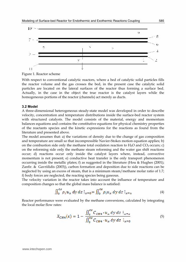
Modeling of Surface-bed Reactor for Endothermic and Exothermic Reactions Coupling
585
Figure 1 Reactor scheme
With respect to conventional catalytic reactors where a bed of catalytic solid particles fills the reactor volume and the gas crosses the bed in the present case the catalytic solid particles are located on the lateral surfaces of the reactor thus forming a surface bed Actually in the case in the object the true reactor is the catalyst layers while the homogeneous portions of the reactor (channels) act merely as ducts
32 Model
A three-dimensional heterogeneous steady-state model was developed in order to describe velocity concentration and temperature distributions inside the surface-bed reactor system with structured catalysts The model consists of the material energy and momentum balances equations and contains the constitutive equations for physical chemistry properties of the reactants species and the kinetic expressions for the reactions as found from the literature and presented above The model assumes that a) the variations of density due to the change of gas composition and temperature are small so that incompressible Navier-Stokes motion equation applies b) on the combustion side only the methane total oxidation reaction to H2O and CO2 occurs c) on the reforming side only the methane steam reforming and the water gas shift reactions occur d) reactions occur only inside the catalyst layers where instead convective momentum is not present e) conductive heat transfer is the only transport phenomenon occurring inside the metallic plates f) as suggested in the literature (Hou amp Hughes (2001) Zanfir amp Gavriilidis (2003)) carbon formation and deposition due to side reactions can be neglected by using an excess of steam that is a minimum steammethane molar ratio of 17 f) body forces are neglected the reacting species being gaseous The velocity variation in the reactor takes into account the influence of temperature and composition changes so that the global mass balance is satisfied
(4)
Reactor performance were evaluated by the methane conversions calculated by integrating the local molar flow rates
(5)
wwwintechopencom
Recent Advances in Modelling and Simulation
586
According to Figure 1 for each catalyst layer and channel and for the metal sheets the due momentum energy and mass balances were set together with the proper boundary conditions in the rectangular coordinates (xndashyndashz) (Cartesian coordinates are indicated in Figure 1 and the z direction is perpendicular with respect to the scheme) with dependent variables velocity components pressure temperature (T) and species concentrations (ci) Equations vectorial formulation are reported in the following so they are valid for both 2D and 3D formulations
Combustion channels 1 and 9 and steam reforming channel 5 Momentum balance
(6)
(7)
Boundary conditions are bull specified velocity with normal component at the channel ingress
bull no slip at the channel boundaries in the y (2D and 3D) and z (3D) directions
bull specified pressure at the channel exit P = P0 With reference to Figure 1 for the momentum balance equations the boundaries of channels 1 and 9 are the external boundaries (10 and 11) of the reactor and the internal boundaries between the channels and the catalyst layers respectively while the boundaries of channel 5 are the internal boundaries between the channel and the catalyst layers Energy balance
(8)
Boundary conditions are bull specified temperature at the channel ingress
bull convective heat flux at the channel exit bull Channels 1 and 9 no heat flux through the channel external boundaries in the y (2D and
3D) and z (3D) directions ie and thermal continuity
at the internal boundaries (l gas
phase and catalyst phase)
bull Channel 5 thermal continuity at the
internal boundaries (l gas phase and catalyst phase) Mass balances
(9)
Boundary conditions are
bull specified concentrations at the channel ingress
bull continuity through the boundary between the gas phase and the catalyst layer ie where and
bull convective mass flux at the channel exit where i and j subscript refers to the ith and jth specie respectively
wwwintechopencom
Modeling of Surface-bed Reactor for Endothermic and Exothermic Reactions Coupling
587
Catalyst Layers 2 and 8 Energy balance
(10)
Boundary conditions are bull thermal continuity at the layers boundaries in the y directions (2D and 3D)
(l gas phase and catalyst phase)
bull thermal insulation at the layer boundaries in the x (2D and 3D) and z (3D) directions
Mass balances
(11)
being θi the stoichiometric coefficient of the ith specie Boundary conditions are bull continuity through the boundary between the layer and the gas phase
where and
and no mass flow between the layer and the metal sheets in the y (2D and 3D) direction
bull no mass flux through the layer boundaries in the x (2D and 3D) and z (3D) directions
Metal sheets 3 and 7 Energy balance
(12)
Boundary conditions are bull thermal insulation at the sheet boundaries in the x (2D and 3D) and z (3D) directions
bull thermal continuity on the sheet boundaries in the y direction (2D and 3D)
Catalyst Layers 4 and 6
Energy balance
(13)
Boundary conditions are bull thermal insulation at the layer boundaries in the x (2D and 3D) and z (3D) directions
bull thermal continuity on the layers boundaries in the y direction (2D and 3D)
Mass balances
(14)
being θji the stoichiometric coefficients of the i specie in the j reaction
wwwintechopencom
Recent Advances in Modelling and Simulation
588
Boundary conditions are bull continuity through the boundary between the layer and the gas phase
where and
and no mass flow
between the catalyst layer and the metal sheet in
the y (2D and 3D) direction bull no mass flux through the layer boundaries in the x (2D and 3D) and z (3D) directions
In the balances above the gas densities were calculated using the ideal gas law whereas for catalyst density a constant value was assumed Viscosities and thermal conductivities of the gaseous species refer to the values of the component largely in excess in the specific gas mixtures that is H2O for the steam reforming channel and air for the combustion channels Their dependence of the temperature was excerpted from experimental values from the literature (Perry amp Green (1997)) and included as interpolated functions inside the calculation software To work out heat capacities expressions such as
(15)
were used where A B and C were evaluated by the regression of an expression (Perry amp Green (1997) such as
(16)
The diffusivity coefficients were calculated for a binary mixture between component ith and H2O (in the reforming channel) or air (in the combustion channels) The effective diffusion coefficient inside the catalyst layer is (Perry amp Green (1997)
(17)
where is the catalyst porosity τ the tortuosity and Dij the Knudsen diffusion coefficient and the molecular diffusion coefficient of the ith specie in the jth specie respectively Molecular diffusion coefficients were evaluated using (Perry amp Green (1997))
(18)
where T is the temperature in [K] π the total pressure of the system in [Pa] Mi and Mj the molecular weights of ith and jth species respectively and φi the atomic diffusion volumes characteristic for each component (Perry amp Green (1997)) Knudsen diffusion coefficients were evaluated using (Perry amp Green (1997))
(19)
where Rp is the mean pore radius and T the temperature into the catalyst
wwwintechopencom
Modeling of Surface-bed Reactor for Endothermic and Exothermic Reactions Coupling
589
33 Numerical stuff and reference case simulation
The finite element solution algorithm was completed using COMSOL Multiphysics (Comsol Inc version 33a) Multiphysics modules of incompressible Navier-Stokes convectionndashdiffusion and conductionndashconvection were applied when appropriate to the three-phase domains Meshing parameters were different for the 2D and the 3D FEM schemes In particular in the case of 2D a mapped mesh scheme was employed with rectangular extra fine meshes and edge vertex distribution as follows longitudinal edges 1001 transverse edges 51 (metallic plate) and 101 (catalyst layers and channels) In the case of 3D predefined mesh sizes extra coarse with characteristics listed in Table 3 were employed
Number of degrees of freedom 381162
Number of mesh points 6976
Number of elements 33702
Tetrahedral 33702
Number of boundary elements 12840
Triangular 12840
Number of edge elements 740
Number of vertex elements 24
Minimum element quality 0158
Element volume ratio 0015
Table 3 Mesh Statistics
A reference case with given reactor geometric configuration and operating conditions was chosen to carry out a reference case simulation Other simulations were carried out to explore the influence on the reactor performance of specific geometrical andor operating parameter changes The conditions used in the calculations for the reference case are listed in Table 4 Inlet conditions for the reforming side are similar to those used by Xu and Froment (1989b) but for the total pressure close to atmospheric in our case 29 bar characteristic of industrial operation in the kinetics from Xu amp Froment This because as suggested in the literature (Kolios et al 2004) small-scale hydrogen production which is the potential application for such type of reactor is expected to operate at low pressure This represents a limit of the present work However similar detailed rate equations for the investigated reacting system are not available at ambient pressure in the literature Data reported in Table 4 show that the inlet reforming reaction mixture has a steammethane ratio of 3 and contains trace amounts of CO2 H2 and CO On the methane combustion side the airndashmethane mixture has a 40 air excess with respect to stoichiometric The inlet temperature of both streams is 800 K that is close to that typical of industrial steam reforming The inlet methane mass flow rate in the reforming channel is fixed at 167 cm3s at STP while the inlet methane mass flow rate in the combustion channel is obtained from an overall heat balance The data for reforming catalyst used in the calculations are typical for such a reaction and similar to that used by Xu amp Froment (1989a) for a catalyst containing 152 Ni supported on MgO-αAl2O3
wwwintechopencom
Recent Advances in Modelling and Simulation
590
Table 4 Data used for reference case calculations
Figure 2 Temperature space profiles along the reactor centerline of the reforming channel (solid blue) centerline of the combustion channel (solid red) centerline of the reforming catalyst (dashed blue) and centerline of the combustion catalyst (dashed red)
Gas phase Reforming channel Combustion channels Inlet conditions co-current flow compositions vol H2O 6666 CH4 3333 750 CO2 1 10-3 CO 1 10-3 O2 1943 N2 7307 H2 1 10-3 temperature 800 K 800 K CH4 mass flow rate cm3s (STP) 167 0417 pressure 101 kPa (channel outlet) 101 kPa (channel outlet) channel width m 2 10-3 1 10-3 channel height m 10 10-2 average velocity ms 097 087 channel length m 5 10-2 Catalyst layers thickness (c) μm 200 Average pore radius nm 15 porosity 05 tortuosity 4 Metal plates Thickness m 5 10-4 material aluchrom Thermal conductivity w(m K) Temperature dependent
wwwintechopencom
Modeling of Surface-bed Reactor for Endothermic and Exothermic Reactions Coupling
591
Figure 3 Axial profiles of heat flux in the y direction adjacent to the reforming catalyst in the metallic plate (solid line) in the reforming channel (dotted line)
The catalyst layer density is assumed to be 2300 kgm3 For both type of catalyst layers an average pore radius of 15 nm together with a porosity of 05 and a tortuosity factor of 4 are considered These values are typical for both combustion and reforming catalysts (De Deken et al 1982 Xu amp Froment 1989 b Groppi et al 1995)
4 Results
41 Thermal behaviour
Given the symmetry of the reactor for both 3D and 2D simulations only half of the reactor was simulated by substituting the proper boundary conditions (symmetry) in place of the lacking half Results in simulations performed with the 2D model under the reference case conditions are shown in Figures 2-7 The first aspect to consider is the thermal coupling of steam reforming with catalytic combustion in terms of evolution of both exothermic and endothermic conversion Figure 2 shows the temperature longitudinal profiles on the centerlines of the combustion and the reforming channels and in the combustion and reforming catalysts The profiles are very close each other and they increase from the inlet value of 800 to 914 K at the reactor outlet Therefore the catalytic combustion provides the necessary heat flux to heat up both reaction mixtures and to simultaneously drive the endothermic process A methane conversion at the reactor outlet of 089 for combustion and 074 for reforming are achieved Figure 3 shows the axial profiles of the absolute values of the heat fluxes in the y direction at the boundaries of the reforming catalyst One profile (solid line) is the heat flux from the metallic plate towards the reforming catalyst the other the heat flux from the reforming catalyst to the gas mixture in the reforming channel The two profiles present similar shapes with a maximum at 7 mm and 5 mm from the reactor entrance (distances within which the profiles are increasing) The difference between the profiles represents the heat absorbed by the reforming reaction system (eqs (1) and (2)) The maxima heat fluxes generated and consumed reach values of the order of 105 Wm2 ie 10 Wcm2 that considering the very small temperature gradients (Figure 2) is a very high value with respect to that attainable in industrial practice
wwwintechopencom
Recent Advances in Modelling and Simulation
592
a)
b)
Figure 4 Reactor temperature transverse profiles a at 15 cm from the reactor entrance b at 10 cm from the reactor outlet From 0 to 1 reforming channel From 1 to 12 reforming catalyst From 12 to 17 metallic plate From 17 to 19 combustion catalyst From 19 to 24 combustion channel
A further aspect to be examined is the magnitude of the transverse temperature gradients From Figure 2 it is already evident that the four profiles are very close each other However the transverse temperature gradients can be better analyzed from Figure 4 where the transverse temperature profiles at 15 cm (Figure 4a) from the reactor entrance and at 05 cm (Figure 4b) from the reactor outlet are shown In particular Figure 4a which pertains to the distance from the reactor inlet where the highest transverse temperature gradients develop evidences that the maximum temperature difference between reforming and combustion catalyst is 07 K while the maximum difference between the reforming and combustion channels is less than 10 K although that inside the reforming channel is almost 20 K Much lower differences can be observed close to the reactor outlet Specifically Figure 4b shows that the maximum temperature difference between reforming and combustion catalyst is 01 K that between the reforming and combustion channels is less than 1 K and that inside the reforming channel is almost 2 K As a result the high thermal conductivity of the metallic
wwwintechopencom
Modeling of Surface-bed Reactor for Endothermic and Exothermic Reactions Coupling
593
wall makes possible an efficient heat transfer at a temperature difference of the order of tenths of K With reference to Figure 4 it must be remarked that the value 0 of the transverse coordinate represents the centre of the reactor and the centre of the reforming channel Therefore at that point there is not a physical boundary the heat flux and the momentum flux are both zero and the x component of the gas velocity is maximum On the contrary the value 29 10-3 m of the transverse coordinate represents a solid wall that is the external boundary of the reactor and the boundary of the combustion channel This means that the heat flux is zero both components of the gas velocity are zero and the momentum flux is not zero This is one of the reasons because for the same distance in the transverse direction (y) the gas phase temperature difference in the reforming channel results always larger than that in the combustion channel (Figures 2 4a and 4b)
42 Mass transfer and chemical reactions
The concentration on the centerline of the reforming channel of the various species involved in the reactions occurring within the reforming catalyst are shown in Figure 5 This yields an overall picture of the reactor performance The hydrogen concentration steadily increases from the initial value to about 9 molm3 resulting the most abundant component in the exit gas mixture The ratio between the hydrogen concentration and CO concentration is very high (about 9)
Figure 5 Axial profiles of species concentrations on the centerline of the reforming channel
One important aspect to determine is the effect of interphase mass transport resistance Figure 6a shows the methane concentration axial profiles on the centerlines of the combustion channels and of the combustion catalyst while Figure 6b shows the correspondent profiles for the reforming section of the reactor From these Figures the differences between the channel and the catalyst profiles in each section yield a measure of the resistance to the interphase transport As expected in the combustion section the axial methane concentration profiles both in the channel and in the catalyst show an exponentially decreasing trend which reflects the relatively simple kinetics of the reaction In contrast a more complex trend is shown by the axial methane concentration profile in the catalyst because of the non linearity of the kinetics and the simultaneous occurrence of two
wwwintechopencom
Recent Advances in Modelling and Simulation
594
reactions (eqs (1) and (2)) Another aspect to examine is the size of the concentration gradients in the transverse direction These can be appreciated from Figure 7 where the transverse methane concentration profiles at 15 cm from the reactor inlet and at 05 cm from the reactor outlet are shown In particular the first profile which pertains to the distance from the reactor inlet where the highest transverse temperature gradients develops evidences that the gradients inside the reforming and the combustion channels are negligible with respect to the gradients in the catalyst phase The order of magnitude of these latter range from 105 molm4 close to the reactor inlet to 104 molm4 in the remaining part of the reforming catalyst and in all the combustion catalyst too
a)
b)
Figure 6 Axial methane concentration profiles along the reactor (a) solid line combustion channel dashed line combustion catalyst (b) solid line reforming channel dashed line reforming catalyst
wwwintechopencom
Modeling of Surface-bed Reactor for Endothermic and Exothermic Reactions Coupling
595
Figure 7 Methane concentration transverse profiles at 15 cm from the reactor entrance (solid line) and at 10 cm from the reactor outlet (dashed line) From 0 to 1 reforming channel From 1 to 12 reforming catalyst From 12 to 17 metallic plate From 17 to 19 combustion catalyst From 19 to 24 combustion channel
43 Methane concentration in the combustion channel
A basic requirement of the system in the object which is thought to be used for energy feeding of portable electric devices should be the complete reliability with respect to possible uncontrolled rises in temperature or even to a possible explosion hazard In this view the coordination between exothermic and endothermic reaction rates appears fundamental However even in the case such a coordination occurs the possible progress of the combustion reaction in the homogeneous phase may represent an hazard In addition if the concentration of the reacting mixture entering the combustion channel is within the flammability limits and the temperature becomes high enough it could ignite before the reactor inlet Therefore for safety purposes the occurrence of the exothermic reaction here represented by the methane combustion in the homogeneous phase should be avoided A possible way to make the system of hydrogen generation intrinsically safe is to feed the combustion mixture at a methane concentration below the LEL (lower explosivity limit) Considering that at STP the LEL of methane in air is about 5 vol that the autoignition temperature for airmethane mixtures is around 900 K the extimated LEL of methane in air at such a temperature should be about 3 vol (Crowl amp Louvar (2002)) Therefore a safe operating concentration should be about 3 vol To this purpose in this work beside those carried out under the conditions considered in the reference case other simulations were effected for which for a given methane mass flow rate its concentration at the combustion channel inlet was kept below 3 vol In this way the system is intrinsically safe because the reacting mixture cannot ignite spontaneously In addition the simulation becomes more realistic the contribution to the methane combustion of the homogeneous phase being really absent as implicitly hypothesized in this work
wwwintechopencom
Recent Advances in Modelling and Simulation
596
Figure 8 Temperature distribution over the boundaries of the 3D reactor
The comparison of results of runs performed under these conditions with those effected under the conditions of the reference case are reported in the following when analyzing the influence of various parameters on the reactor performance These simulations are labeled in the paper as n-expl in contrast to the others that are recalled as expl
44 Comparison between 2D and 3D results
For given operating conditions some simulations were carried out in both 2D and 3D geometry In principle a plane 2D geometry represents a slice of the reactor where the z dimension is greatly prevalent with respect to the y dimension Actually the model reactor has not such characteristics the length in the z dimension being 10 mm that is only 5 times the reforming channel width This means that the boundary effects due to the presence of the boundary walls in the z direction may have a significant influence on the velocity temperature and species concentration profiles that certainly influence the overall reactor performance Figures 8 shows the temperature distribution over the boundaries of the 3D reactor obtained under operating conditions of the reference case From this Figure the effect of the boundaries along the z direction appears evident
wwwintechopencom
Modeling of Surface-bed Reactor for Endothermic and Exothermic Reactions Coupling
597
Figure 9 Temperature space profiles along the reactor calculated with the 2D model (for the legend see caption to Figure 2)
Figure 10 Temperature space profiles along the reactor calculated with the 3D model (for the legend see caption to Figure 2)
Figures 9 and 10 show the reactor temperature longitudinal profiles on the centerlines of the combustion and the reforming channels and on the centerline of the combustion and reforming catalysts in the case of 2D and 3D geometry models respectively Both were calculated under the same operating conditions ie same inlet mass flow rates and compositions of the reference case (expl) but inlet temperature of 900 K In the case of the
wwwintechopencom
Recent Advances in Modelling and Simulation
598
3D simulation (Figure 10) the temperature profiles are those lying over a xy plane intersecting the reactor in the middle of its height along z The two sets of profiles appear quite similar the temperatures in the combustion section (catalyst and channel) are always slightly higher than the corresponding ones in the reforming section However a closer inspection reveals some significant differences In the 2D case the temperature after an initial slow growth increases steadily from 900 K at the reactor inlet up to 965 K at the reactor outlet while in the other case it grows faster reaches 960 K at 60 of the reactor length and remains constant up to the outlet Another difference is represented by the larger transverse temperature gradients of the 3D case with respect to 2D In the 2D case they are comparable with those observed in Figure 2 for the reference case while in the 3D case they are almost double This is true for all combinations ie catalyst-catalyst catalyst-channel and channel-channel On the whole the 3D case shows a faster progress of the reactions with consequent need for faster heat transfer These differences in the thermal behaviour between 2D and 3D simulations persist when the comparison is extended to other operating conditions and in addition they reflect the better overall performance of the 3D reactor with respect to the 2D as can be seen by the following discussion The quantitative comparison between the 2D and 3D simulations was made with respect to the main results ie the methane conversion in both the combustion and the steam reforming channels as obtained from equation 5 Further beside the methane conversions other parameters are employed ie a) the gas hourly space velocities GHSV in the combustion and steam reforming sides of the reactor calculated as ratio between gas flow rates at the reactor inlet temperature and volume of catalyst b) the maximum temperature reached in the reactor c) the mean gas residence time trm in both the combustion and the reforming channel calculated as ratio between the gas flow rates at the reactor inlet temperature and the volume of the channel and d) the hydrogen yield φH2 evaluated as ratio between the amounts of methane reacted and hydrogen produced GHSV and trm were useful to allow the comparison of simulations carried out by changing the catalyst volume or the channel width as discussed later Results of simulations carried out with the 2D and 3D models under various operating conditions are reported in Table 5 Those referring to the operating conditions of the reference case are listed in the first two rows of such a Table The other operating conditions are i) same inlet temperature of the reference case but different methane concentration in the combustion channel (3rd and 4th rows of Table 5) and ii) different inlet temperatures for the two conditions above (5th-8th rows of Table 5) Focusing the comparison on the results of the simulations in 2D and 3D with the same operating conditions it appears that in general the methane conversions at the reactor outlet calculated with the 2D geometry in both the combustion and reforming channels are lower than the correspondent in 3D geometry but in one case (Xch4-sr 3rd and 4th rows of the Table) This finding reflects the differences in the thermal behaviour discussed above In any case such conversions differ by less than 10 but in the last two rows of the Table where the differences are larger It is worth noting however that even in this case the values of the conversions are congruent with the overall results of the simulation For instance the lower value of Xch4-co in the 2D with respect to the correspondent in 3D results in a lower value of Xch4-sr and in a lower maximum temperature reached in the reactor
wwwintechopencom
Modeling of Surface-bed Reactor for Endothermic and Exothermic Reactions Coupling
599
Geometry Tin K
Xch4-co Xch4-sr Tmax K Trm-co ms
Trm-sr ms
GHSVco h-1
GHSVsr h-1
φH2
2D expl 800 089 074 914 0057 0026 314840 702884 329
3D expl 800 096 077 914 0057 0026 314840 702884 333
2D n-expl 800 036 045 827 0020 0026 900588 702884 344
3D n-expl 800 040 041 828 0020 0026 900588 702884 356
2D expl 900 095 090 965 0051 0023 354194 790745 305
3D expl 900 099 093 960 0051 0023 354194 790745 300
2D n-expl 900 049 069 900 0018 0023 1013162 790745 322
3D n-expl 900 068 079 920 0018 0023 1013162 790745 318
Table 5 Comparison of 2D and 3D results obtained under the same operating conditions
For what concerns the hydrogen yield focusing again the comparison on the results of the simulations in 2D and 3D at the same operating conditions data show that φH2rsquos obtained with the 2D geometry model are lower than that in 3D model but in one case (7th and 8th row of Table 5) It is worth noting that φH2=3 would be the stoichiometric value if reaction (1) were the only occurring in the reforming catalyst so that the amount exceeding 3 is due to the contribution of reaction (2) Data in Table 5 also shows the influence on the reactor performance of temperature and inlet methane concentration in the combustion channel In the case of inlet temperature of 900 K and methane concentration within the explosivity limits (case referring to results in Figures 9 and 10) the methane conversion is practically 1 (3D model) for the combustion reaction and very high for the reforming reactions However under these conditions the hydrogen yield is the lowest In contrast when the highest hydrogen yield is reached the lowest methane conversion is achieved Similar considerations can be done for the other results in the Table so that a general trend can be drawn from such results The higher the maximum temperature reached in the reactor the higher the methane conversions and the lower the hydrogen yield
45 Influence of the channels width
The reactor thermal behaviour and performance was studied for different channels width Wc at constant inlet flow rates of the reaction mixtures Runs were also carried out by keeping constant the mean inlet velocities of reaction mixtures The variation range for the combustion channels width Wc-co was 1-15 mm and for the reforming channel width Wc-sr 2-3 mm All other parameters were kept at their reference case values Keeping constant the inlet mass flow rates and altering the channel width results in modifying the inlet velocities in the reactor and consequently the mean residence time (trm) of the gases in the channels but the GHSVrsquos do not change The results in terms of methane conversions in the combustion and reforming channels are reported in Table 6 for the reference cases (3rd and 4th row in Table) and for cases where the methane concentration in the combustion channels were below the LEL (1st and 2nd row) At constant mass flow rates the influence of the channel width or better of trm appears negligible under n-expl conditions with a slight
wwwintechopencom
Recent Advances in Modelling and Simulation
600
prevalence of the reactor with narrower channels and weak under expl conditions with in contrast better performance for the reactor with wider channels Therefore it is not possible to draw conclusions
Wc-sr mm
Tin K
Xch4 -
co Xch4-sr
Tmax K
trm-co ms
trm-sr ms
GHSVco h-1
GHSVsr h-1
2 n-expl 800 036 045 827 0020 0026 900588 702884
3 n-expl 800 034 044 819 0030 0038 900588 702884
2 expl 800 089 074 914 0057 0026 314840 702884
3 expl 800 092 081 940 0086 0038 314840 702884
Vcost- 3 n-expl 800 022 033 800 0020 0026 1350882 1054327
Table 6 Comparison between reactor performance as a function of channel width
Unlike the previous case where inlet flow rates were kept constant an increase in channel width keeping the mean gas velocity and the value of trm constants affects significantly the outlet conversions In this case the amount of reactants flowing through the reactor per unit catalyst volume and then GHSV increases (compare 1st and 5th rows in Table 5) Increasing channel widths from their reference case value (Wc-sr = 2 mm and Wc-co= 1) at constant gas inlet velocity leads to methane conversion reduction because a) the catalyst amount becomes insufficient for the amount of reactants fed in the reactor and b) the external mass transfer resistances play a stronger role The overall reaction heat fluxes remain the same as channel width increases leaving a similar amount of sensible heat to be used for heating up larger amounts of reactants This results in lower temperatures along the reactor
46 Influence of catalyst thickness
The influence of catalyst thickness c on the reactor behaviour was studied by keeping constant the reactants mass flow rates The reactor operation was simulated for three values of catalyst thickness ie 200 100 and 50 microm while keeping all the other parameters at their reference case values but for what concerns the inlet methane concentration in the combustion channel that was at non explosive level This with respect to the reference case corresponds to decreasing GHSV of factors 2 and 4 respectively Changes in the catalyst thickness influence considerably both thermal behaviour and outlet conversions As above the comparison is made through the methane conversions achieved in the two cases both in the steam reforming and in the combustion channels The results are reported in Table 7 It is evident that the loss of performance due to a decrease of 50 of c from 200 to 100 μm is almost negligible This is mainly due to the conservative parameters used for defining the catalyst layer characteristics (ie mean pore radius and tortuosity) that results in a very impervious path for diffusing gases However when c is further decreased methane conversion both in the combustion and in the reforming section significantly decrease The hydrogen yield does not change too much within the limits of the three cases analyzed
wwwintechopencom
Modeling of Surface-bed Reactor for Endothermic and Exothermic Reactions Coupling
601
δc μm
Tin K Xch4 -co Xch4-sr Tmax Ktrm-co ms
trm-sr ms
GHSVco h-1
GHSVsr h-1
φH2
200 n-expl 800 036 045 827 0020 0026 900588 702884 344
100 n-expl 800 035 045 827 0020 0026 1801176 1405768 344
50 n-expl 800 027 038 800 0020 0026 3602352 2811536 342
Table 7 Comparison between reactor performance as a function of catalyst thickness
5 Discussion
As seen in the previous section (4) there are several operating parameters that influence the performances of the system They are typical of reacting systems and can be summarized as GHSVrsquos tmrrsquos and inlet gas temperatures The particularity of the present case is the simultaneous occurrence of two coupled reactions one exothermic and the other endothermic in which the extent of the second depends on the extent (heat produced) of the first and the effectiveness of the heat transferred In addition the coupling of the two reactions does not exclude to have for each set of values of the mentioned parameters pertaining to one reaction several sets of parameters for the other reaction This makes the system quite complex and difficult to analyze However some general considerations can be drawn
Figure 11 Methane conversions in the combustion and reforming sides of the reactor as a function of GHSV for various operating conditions available in Table 6 and 7
The first is that as expected GHVS plays a key role in determining the reactor performances although this is supported by only a part of the data For instance data in Table 7 pertaining to simulations of the influence of such a parameter carried out by changing GHSV in the same way for both sections of the reacting system shows a clear effect of GHSV the reactor
0 1000000 2000000 3000000 4000000
GHSV h-1
02
04
06
08
1
XC
H4
-co a
nd
XC
H4
-sr -
data from Table 7 comb side
data from Table 7 refor side
data from Table 6 comb side
data from Table 6 refor side
wwwintechopencom
Recent Advances in Modelling and Simulation
602
performance decreases as GHSV increases on both sides of the reactor Such an influence does not appear strong the conversion change being about 20 against GHSV variations of a factor 4 (Figure 11) The influence of GHSV is more evident from data in Table 6 pertaining to simulations of the influence of tmr In fact also in this case a clear trend appears and the influence even though in the same direction of the previous case appears much stronger since with respect to a GHSV change of about 20 the methane conversion varies by a factor 4 (Figure 11) Such a strong influence is due to the combined effect of tmr especially on the combustion side of the reactor (cfr Table 6) Instead for data in Table 5 pertaining to simulations of the reliability of 2D and 3D models and the effect of gas inlet temperature it is not possible to highlight a clear influence The comparison between the results obtained with the 2D and 3D models under the same operating conditions have evidenced differences in the performance of the reactor not large but significant When we move from 2D to 3D models such differences result in an increase from 5 to 20 of both Xch4-co and Xch4-sr which reflects a different thermal behavior of the reacting system and influence also the hydrogen yield It is worth noting that the computation time required in the two cases is very different Specifically using an HP xw8400workstation equipped with 2 Xeon processors and 4 GB of RAM a 2D simulation takes on the average about 20 minutes with respect to 50-60 hours necessary in the 3D case It is impossible by now to establish which is the more correct or the more reliable In particular it should be assessed if 2D simulations are suitable for purpose of reactor design and experimental data interpretation The answer should come from the comparison of the results of such simulations with experimental data obtained with a real reactor geometrically comparable operated under conditions as much as similar to those fixed for the simulations This represents argument for coming work of the authors Further interesting aspects to be studied are the simulation of unsteady-state conditions and specifically of the system start-up and of the system response to small changes in the gas feeding flow rates and temperatures
6 Conclusions
Methane steam reforming coupled with methane catalytic combustion by means of indirect heat transfer in a surface-bed catalytic reactor was studied by 2D and 3D models The reactor consists of a central reforming channel and two lateral combustion channels A reference case for what concerns operating conditions and reactor geometry was chosen and its simulation was carried out Changes of reactor performance as consequence of operating parameters and reactor geometry variations were analyzed with respect to the reference case The simulation showed that suitable amount of fuel and adequate catalyst activity in the combustion channel can provide enough heat to simultaneously heat up the reaction mixture and drive the endothermic process The proximity between the heat source and the heat sink increases the efficiency of heat transfer resulting in transverse temperature gradients do not exceeding generally 07 K across the metallic wall and 20 K across the gas in the channel Decrease of transverse temperature differences and intraphase mass transfer resistances have the global effect of reducing the reactor dimension and the catalyst amount The influence of channels width and catalyst layer thickness on reactor behaviour was also studied At constant inlet flow rates changes of channel width in the range 1ndash2 mm do not introduce significant differences in the reactor performance Rather small differences in the
wwwintechopencom
Modeling of Surface-bed Reactor for Endothermic and Exothermic Reactions Coupling
603
catalyst axial temperature profiles and outlet methane conversions are observed In contrast altering the channel width at constant inlet velocities has strong influence Larger channel width results in lower conversion and smoother axial temperature profiles Intraphase resistances are present even for catalyst thickness of micrometers for both reforming and combustion processes Increasing GHSV that is the inlet flow ratecatalyst volume ratio leads to lower outlet conversions Due to different effect of catalyst layer thickness on reforming and combustion channels there are significant changes in the reactor temperature profile Results indicate that steam reforming of methane in a surface-bed reactor is feasible provided that mass flow rates channels width catalyst loadings and thickness are properly designed
7 Notation
cp specific heat J(mol K) c concentration molm3 Deff effective diffusion coefficient m2s D molecular diffusion coefficient m2s GHSV gas hourly space velocity h-1 k thermal conductivity W(m K) or reaction rate constant Ke equilibrium constant M molecular weight kgmol LEL lower explosivity limit vol
unit vector perpendicular to the flux surface
N molar flux at the boundary mol(m2 s) p partial pressure bar P total pressure bar q thermal flux at the boundary J(m2 s) r reaction rate various dimensions (see eqs 1rsquo 2rsquo and 3rsquo) Rp catalyst pore radius nm STP standard temperature and pressure (298 K and 101 103 Pa) t time s T temperature K ts transverse surface ux Velocity component on the x coordinate
velocity vector
v normal component of velocity at the channel ingress x axial coordinate m X conversion y transverse coordinate m Wc distance between the reactor plates m z vertical coordinate m Greek letters ΔH0r heat of reaction at reference state conditions KJmol c catalyst thickness μm catalyst porosity φ atomic diffusion volume or chemical reaction yield
wwwintechopencom
Recent Advances in Modelling and Simulation
604
θ stoichiometric coefficient ρ density kgm3 τ catalyst tortuosity
Subscripts and superscripts cat catalyst co combustion CH4 methane H2 hydrogen in inlet i chemical species j channel k reaction l phase rm mean residence s metal sheet sr steam reforming 0 channel ingress 1 reforming reaction 2 water gas shift reaction 3 combustion reaction
8 Acknowledgements
The authors gratefully acknowledge the financial support of MIUR under grant PRIN ndeg 2006094333004
9 References
Akers WW amp Camp DP (1955) Kinetics of the methanendashsteam reaction AIChE Journal Vol 1 471ndash475 ISSN0001-1541
Allen DW Gerhard ER amp Likins Jr MR (1975) Kinetics of the MethanendashSteam Reaction Ind Eng Chem Proc Des Dev Vol 14 No 3 256-259 ISSN0196-4305
Aparicio L (1997) Transient Isotopic Studies and Microkinetic Modeling of Methane Reforming over Nickel Catalysts Journal of Catal Vol 165 No 2 262-274 ISSN 0021-9517
Avci AK Trimm DL amp İlsen Oumlnsan Z (2001) Heterogeneous reactor modeling for simulation of catalytic oxidation and steam reforming of methane Chem Eng Sci Vol 56 No 2 641-649 ISSN0009-2509
Bridger GW (1980) The steam reforming of hydrocarbons Catalysis Vol 3 39-69 ISSN0140-0568
Cao C Wang Y amp Rozmiarek RT (2005) Heterogeneous reactor model for steam reforming of methane in a microchannel reactor with microstructured catalysts Catal Today Vol 110 No 1-2 92ndash97 ISSN 0920-5861
Craciun R Shereck B amp Gorte RJ (1998) Kinetic studies of methane steam reforming on ceria-supported Pd Catal Lett Vol 51 No 3ndash4 149-153 ISSN 1011-372x
wwwintechopencom
Modeling of Surface-bed Reactor for Endothermic and Exothermic Reactions Coupling
605
Crowl DA amp Louvar JF (2002) Chemical Process Safety fundamentals with applications 2nd ed Prentice Hall PTR Upper Saddle River NJ USA ISBN 0-13mdash018176-5
De Deken J C Devos E F amp Froment G F (1982) Steam reforming of natural gas Intrinsic kinetics diffusional influences and reactor design ACS Symposium Series 196 181ndash197 ISSN0097-6156
Ehrfeld W amp Hessel V Lowe H (2000) Microreactor Wiley-VCH Verlag GmbH D-69469 ISBN Weinheim Germany
Gosiewski K (2001) Simulations of non-stationary reactors for catalytic conversion of methane to synthesis gas Chem Eng Sci Vol 56 No 4 1501-1510 ISSN
Groppi G Belloli A Tronconi E Forzatti P (1995) A comparison of lumped and distributed models of monolith catalytic combustors Chem Eng Sci Vol 50 No 17 2705ndash2715 ISSN0009-2509
Holladay JD Wang Y amp Jones E (2004) Review of Developments in Portable Hydrogen Production Using Microreactor Technology Chem Rev Vol 104 No 10 4767-4790 ISSN 0009-2665
Hou K amp Hughes R (2001) The kinetics of methane steam reforming over a Ni-Al2O3 catalyst Chem Eng Journal Vol 82 No 1-3 311-328 ISSN 1385-8947
Jamal Y amp Wyszynski M L (1994) On-board generation of hydrogen-rich gaseous fuels a review Int J of Hydrogen Energy Vol 19 No 7 557-572 ISSN 0360-3199
Jensen KF (2001) Microreaction engineering is small better Chem Eng Sci Vol 56 No 2 293-303 ISSN0009-2509
Kolios G Gritsch A Glo1ckler B amp Sorescu G (2004) Novel Reactor Concepts for Thermally Efficient Methane Steam Reforming Modeling and Simulation Ind Eng Chem Res Vol 43 No 16 4796-4808 ISSN0888-5885
Kruger P Blakeley J amp Leaver J (2003) Potential in New Zealand for use of hydrogen as a transportation fuel Int J of Hydrogen Energy Vol 28 No 8 795ndash802 ISSN 0360-3199
Kvamsdal HM Svendsen HF Hertzberg T amp Olsvik O (1999) Dynamic simulation and optimization of a catalytic steam reformer Chem Eng Sci Vol 54 No 13-14 2697-2706 ISSN0009-2509
Lerer M Duic N Alves LM amp Carvalho MG (2006) H2 RES energy planning tool for increasing the penetration of renewable energy sources in island energy supply In New and Renewable Technologies for Sustanaible Development MG Carvalho and NH Afgan (Ed s) 15-30 World Scientific ISBN 10 981-270-505-8 Singapore
Lerou JJ amp Ng KM (1996) Chemical reaction engineering A multiscale approach to a multiobjective task Chem Eng Sci Vol 51 No 10 1595-1614 ISSN0009-2509
Lincoln SF (2006) Challenged Earth ch7 Imperial College Press ISBN 1-86094-526-0 London
Loffler D G Faz C F Sokolovskii V amp Iglesia E (2002) Catalytic separator plate reactor and method of catalytic reforming of fuel to Hydrogen PCT Int Appl WO 0228769 A2
Luna C amp Becerra AM (1997) Kinetics of methane steam reforming on a Ni on alumina-titania catalyst React Kinet Catal Lett Vol 61 No 2 369-374 ISSN 0133-1736
Marschner F Renner HJ amp Boll W (2005) Electronic Encyclopedia Release 2005 7th ed in Ullmannrsquos Encyclopedia of Industrial Chemistry M Bohnet et al (Eds) Vol a12 John Wiley amp Sons ISBN-13 978-3-527-30385-4
wwwintechopencom
Recent Advances in Modelling and Simulation
606
Moore R B amp Raman V (1998) Hydrogen infrastructure for fuel cell transportation Int J of Hydrogen Energy Vol 23 No 7 617-620 ISSN 0360-3199
Perry RH amp Green DW (1999) Perrys Chemical Engineers Handbook (7th Ed) McGraw-Hill ISBN 0-07-049841-5
Robbins F A Zhu H amp Jackson GS (2003) Transient modeling of combined catalytic combustionCH4 steam reformng Catal Today Vol 83 No 1-4 141ndash156 ISSN 0920-5861
Rostrup-Nielsen JR Christiansen LJ amp BakHansen JH (1988) Activity of steam reforming catalysts Role and assessment Appl Catal Vol 43 No 2 287-303 ISSN0166-9834
Rostrup-Nielsen JR (1995) Innovation and the catalytic process industry - the science and challenge Chem Eng Sci Vol 50 No 24 4061-4071 ISSN0009-2509
Rostrup-Nielsen JR Dybkjaer I amp Coulthard GRG (2001) Topical Conf Proc AIChE Spring National Meeting Houston TX April Paper No 1
Rostrup-Nielsen JR (2004) Fuels and Energy for the Future The Role of Catalysis Catal Rev - Science and Engineering Vol 46 No 3ndash4 247-270 ISSN0161-4940
Schubert K Brandner J Fichtner M Linder G Schyhulla U amp Wenka A (2001) Microstructure devices for applications in thermal and chemical process engineering Microscale Thermophys Eng Vol 5 No 1 17-39 ISSN1089-3954
Tronconi E amp Groppi G (2000) A study on the thermal behavior of structured plate-type catalysts with metallic supports for gassolid exothermic reactions Chem Eng Sci Vol 55 Issue 24 December 6021-6036 ISSN0009-2509
Wang Y Johnson BR Cao C Chin Y Rozmiarek RT Gao Y Tonkovich AL (2005) Engineered catalysts for microchannel reactor applications In Microreactor Technology and Process Intensification Y Wang J Holladay (Eds) 65-73 ACS Symposium Series Vol 914 ISBN-13 9780841239234
Xu J amp Froment GF (1989a) Methane steam reforming II Diffusional limitations and reactor simulation AIChE Journal Vol 35 No 1 97-103 ISSN0001-1541
Xu J amp Froment GF (1989b) Methane steam reforming methanation and water-gas shift I Intrinsic kinetics AIChE Journal Vol 35 No 1 88-96 ISSN0001-1541
Zanfir M amp Gavriilidis A (2003) Catalytic Combustion Assisted Methane Steam Reforming Chem Eng Sci Vol 58 No 17 3947ndash 3960 ISSN0009-2509
wwwintechopencom
Modelling and SimulationEdited by Giuseppe Petrone and Giuliano Cammarata
ISBN 978-3-902613-25-7Hard cover 688 pagesPublisher I-Tech Education and PublishingPublished online 01 June 2008Published in print edition June 2008
InTech EuropeUniversity Campus STeP Ri Slavka Krautzeka 83A 51000 Rijeka Croatia Phone +385 (51) 770 447 Fax +385 (51) 686 166wwwintechopencom
InTech ChinaUnit 405 Office Block Hotel Equatorial Shanghai No65 Yan An Road (West) Shanghai 200040 China
Phone +86-21-62489820 Fax +86-21-62489821
This book collects original and innovative research studies concerning modeling and simulation of physicalsystems in a very wide range of applications encompassing micro-electro-mechanical systems measurementinstrumentations catalytic reactors biomechanical applications biological and chemical sensorsmagnetosensitive materials silicon photonic devices electronic devices optical fibers electro-microfluidicsystems composite materials fuel cells indoor air-conditioning systems active magnetic levitation systemsand more Some of the most recent numerical techniques as well as some of the software among the mostaccurate and sophisticated in treating complex systems are applied in order to exhaustively contribute inknowledge advances
How to referenceIn order to correctly reference this scholarly work feel free to copy and paste the following
Salvatore Vaccaro and Paolo Ciambelli (2008) Modeling of Surface-bed Reactor for Endothermic andExothermic Reactions Coupling Modelling and Simulation Giuseppe Petrone and Giuliano Cammarata (Ed)ISBN 978-3-902613-25-7 InTech Available fromhttpwwwintechopencombooksmodelling_and_simulationmodeling_of_surface-bed_reactor_for_endothermic_and_exothermic_reactions_coupling
copy 2008 The Author(s) Licensee IntechOpen This chapter is distributedunder the terms of the Creative Commons Attribution-NonCommercial-ShareAlike-30 License which permits use distribution and reproduction fornon-commercial purposes provided the original is properly cited andderivative works building on this content are distributed under the samelicense
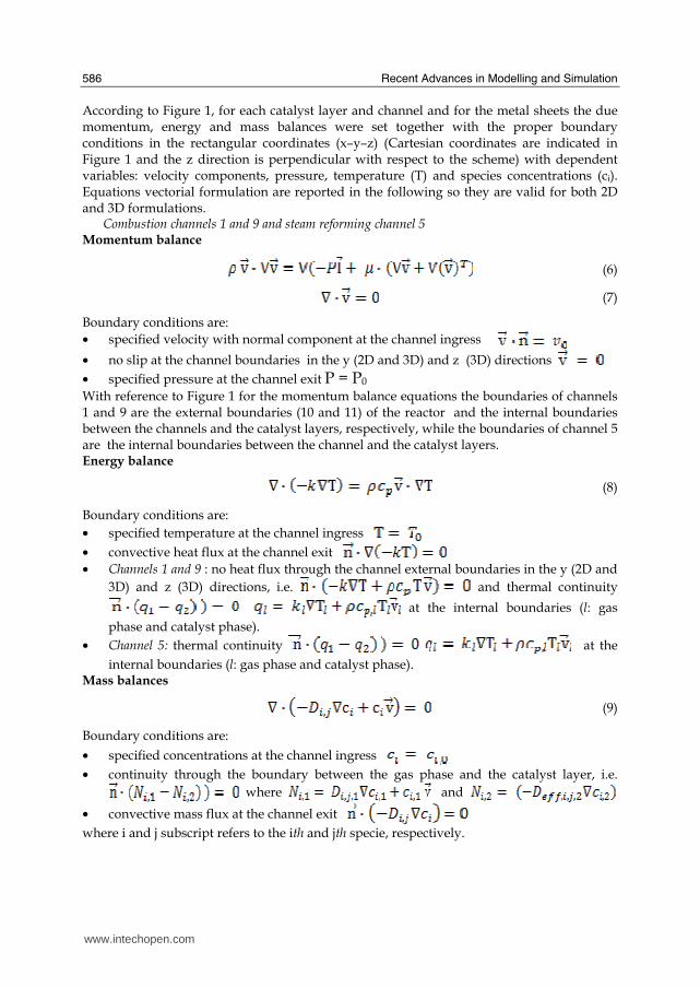
Recent Advances in Modelling and Simulation
586
According to Figure 1 for each catalyst layer and channel and for the metal sheets the due momentum energy and mass balances were set together with the proper boundary conditions in the rectangular coordinates (xndashyndashz) (Cartesian coordinates are indicated in Figure 1 and the z direction is perpendicular with respect to the scheme) with dependent variables velocity components pressure temperature (T) and species concentrations (ci) Equations vectorial formulation are reported in the following so they are valid for both 2D and 3D formulations
Combustion channels 1 and 9 and steam reforming channel 5 Momentum balance
(6)
(7)
Boundary conditions are bull specified velocity with normal component at the channel ingress
bull no slip at the channel boundaries in the y (2D and 3D) and z (3D) directions
bull specified pressure at the channel exit P = P0 With reference to Figure 1 for the momentum balance equations the boundaries of channels 1 and 9 are the external boundaries (10 and 11) of the reactor and the internal boundaries between the channels and the catalyst layers respectively while the boundaries of channel 5 are the internal boundaries between the channel and the catalyst layers Energy balance
(8)
Boundary conditions are bull specified temperature at the channel ingress
bull convective heat flux at the channel exit bull Channels 1 and 9 no heat flux through the channel external boundaries in the y (2D and
3D) and z (3D) directions ie and thermal continuity
at the internal boundaries (l gas
phase and catalyst phase)
bull Channel 5 thermal continuity at the
internal boundaries (l gas phase and catalyst phase) Mass balances
(9)
Boundary conditions are
bull specified concentrations at the channel ingress
bull continuity through the boundary between the gas phase and the catalyst layer ie where and
bull convective mass flux at the channel exit where i and j subscript refers to the ith and jth specie respectively
wwwintechopencom
Modeling of Surface-bed Reactor for Endothermic and Exothermic Reactions Coupling
587
Catalyst Layers 2 and 8 Energy balance
(10)
Boundary conditions are bull thermal continuity at the layers boundaries in the y directions (2D and 3D)
(l gas phase and catalyst phase)
bull thermal insulation at the layer boundaries in the x (2D and 3D) and z (3D) directions
Mass balances
(11)
being θi the stoichiometric coefficient of the ith specie Boundary conditions are bull continuity through the boundary between the layer and the gas phase
where and
and no mass flow between the layer and the metal sheets in the y (2D and 3D) direction
bull no mass flux through the layer boundaries in the x (2D and 3D) and z (3D) directions
Metal sheets 3 and 7 Energy balance
(12)
Boundary conditions are bull thermal insulation at the sheet boundaries in the x (2D and 3D) and z (3D) directions
bull thermal continuity on the sheet boundaries in the y direction (2D and 3D)
Catalyst Layers 4 and 6
Energy balance
(13)
Boundary conditions are bull thermal insulation at the layer boundaries in the x (2D and 3D) and z (3D) directions
bull thermal continuity on the layers boundaries in the y direction (2D and 3D)
Mass balances
(14)
being θji the stoichiometric coefficients of the i specie in the j reaction
wwwintechopencom
Recent Advances in Modelling and Simulation
588
Boundary conditions are bull continuity through the boundary between the layer and the gas phase
where and
and no mass flow
between the catalyst layer and the metal sheet in
the y (2D and 3D) direction bull no mass flux through the layer boundaries in the x (2D and 3D) and z (3D) directions
In the balances above the gas densities were calculated using the ideal gas law whereas for catalyst density a constant value was assumed Viscosities and thermal conductivities of the gaseous species refer to the values of the component largely in excess in the specific gas mixtures that is H2O for the steam reforming channel and air for the combustion channels Their dependence of the temperature was excerpted from experimental values from the literature (Perry amp Green (1997)) and included as interpolated functions inside the calculation software To work out heat capacities expressions such as
(15)
were used where A B and C were evaluated by the regression of an expression (Perry amp Green (1997) such as
(16)
The diffusivity coefficients were calculated for a binary mixture between component ith and H2O (in the reforming channel) or air (in the combustion channels) The effective diffusion coefficient inside the catalyst layer is (Perry amp Green (1997)
(17)
where is the catalyst porosity τ the tortuosity and Dij the Knudsen diffusion coefficient and the molecular diffusion coefficient of the ith specie in the jth specie respectively Molecular diffusion coefficients were evaluated using (Perry amp Green (1997))
(18)
where T is the temperature in [K] π the total pressure of the system in [Pa] Mi and Mj the molecular weights of ith and jth species respectively and φi the atomic diffusion volumes characteristic for each component (Perry amp Green (1997)) Knudsen diffusion coefficients were evaluated using (Perry amp Green (1997))
(19)
where Rp is the mean pore radius and T the temperature into the catalyst
wwwintechopencom
Modeling of Surface-bed Reactor for Endothermic and Exothermic Reactions Coupling
589
33 Numerical stuff and reference case simulation
The finite element solution algorithm was completed using COMSOL Multiphysics (Comsol Inc version 33a) Multiphysics modules of incompressible Navier-Stokes convectionndashdiffusion and conductionndashconvection were applied when appropriate to the three-phase domains Meshing parameters were different for the 2D and the 3D FEM schemes In particular in the case of 2D a mapped mesh scheme was employed with rectangular extra fine meshes and edge vertex distribution as follows longitudinal edges 1001 transverse edges 51 (metallic plate) and 101 (catalyst layers and channels) In the case of 3D predefined mesh sizes extra coarse with characteristics listed in Table 3 were employed
Number of degrees of freedom 381162
Number of mesh points 6976
Number of elements 33702
Tetrahedral 33702
Number of boundary elements 12840
Triangular 12840
Number of edge elements 740
Number of vertex elements 24
Minimum element quality 0158
Element volume ratio 0015
Table 3 Mesh Statistics
A reference case with given reactor geometric configuration and operating conditions was chosen to carry out a reference case simulation Other simulations were carried out to explore the influence on the reactor performance of specific geometrical andor operating parameter changes The conditions used in the calculations for the reference case are listed in Table 4 Inlet conditions for the reforming side are similar to those used by Xu and Froment (1989b) but for the total pressure close to atmospheric in our case 29 bar characteristic of industrial operation in the kinetics from Xu amp Froment This because as suggested in the literature (Kolios et al 2004) small-scale hydrogen production which is the potential application for such type of reactor is expected to operate at low pressure This represents a limit of the present work However similar detailed rate equations for the investigated reacting system are not available at ambient pressure in the literature Data reported in Table 4 show that the inlet reforming reaction mixture has a steammethane ratio of 3 and contains trace amounts of CO2 H2 and CO On the methane combustion side the airndashmethane mixture has a 40 air excess with respect to stoichiometric The inlet temperature of both streams is 800 K that is close to that typical of industrial steam reforming The inlet methane mass flow rate in the reforming channel is fixed at 167 cm3s at STP while the inlet methane mass flow rate in the combustion channel is obtained from an overall heat balance The data for reforming catalyst used in the calculations are typical for such a reaction and similar to that used by Xu amp Froment (1989a) for a catalyst containing 152 Ni supported on MgO-αAl2O3
wwwintechopencom
Recent Advances in Modelling and Simulation
590
Table 4 Data used for reference case calculations
Figure 2 Temperature space profiles along the reactor centerline of the reforming channel (solid blue) centerline of the combustion channel (solid red) centerline of the reforming catalyst (dashed blue) and centerline of the combustion catalyst (dashed red)
Gas phase Reforming channel Combustion channels Inlet conditions co-current flow compositions vol H2O 6666 CH4 3333 750 CO2 1 10-3 CO 1 10-3 O2 1943 N2 7307 H2 1 10-3 temperature 800 K 800 K CH4 mass flow rate cm3s (STP) 167 0417 pressure 101 kPa (channel outlet) 101 kPa (channel outlet) channel width m 2 10-3 1 10-3 channel height m 10 10-2 average velocity ms 097 087 channel length m 5 10-2 Catalyst layers thickness (c) μm 200 Average pore radius nm 15 porosity 05 tortuosity 4 Metal plates Thickness m 5 10-4 material aluchrom Thermal conductivity w(m K) Temperature dependent
wwwintechopencom
Modeling of Surface-bed Reactor for Endothermic and Exothermic Reactions Coupling
591
Figure 3 Axial profiles of heat flux in the y direction adjacent to the reforming catalyst in the metallic plate (solid line) in the reforming channel (dotted line)
The catalyst layer density is assumed to be 2300 kgm3 For both type of catalyst layers an average pore radius of 15 nm together with a porosity of 05 and a tortuosity factor of 4 are considered These values are typical for both combustion and reforming catalysts (De Deken et al 1982 Xu amp Froment 1989 b Groppi et al 1995)
4 Results
41 Thermal behaviour
Given the symmetry of the reactor for both 3D and 2D simulations only half of the reactor was simulated by substituting the proper boundary conditions (symmetry) in place of the lacking half Results in simulations performed with the 2D model under the reference case conditions are shown in Figures 2-7 The first aspect to consider is the thermal coupling of steam reforming with catalytic combustion in terms of evolution of both exothermic and endothermic conversion Figure 2 shows the temperature longitudinal profiles on the centerlines of the combustion and the reforming channels and in the combustion and reforming catalysts The profiles are very close each other and they increase from the inlet value of 800 to 914 K at the reactor outlet Therefore the catalytic combustion provides the necessary heat flux to heat up both reaction mixtures and to simultaneously drive the endothermic process A methane conversion at the reactor outlet of 089 for combustion and 074 for reforming are achieved Figure 3 shows the axial profiles of the absolute values of the heat fluxes in the y direction at the boundaries of the reforming catalyst One profile (solid line) is the heat flux from the metallic plate towards the reforming catalyst the other the heat flux from the reforming catalyst to the gas mixture in the reforming channel The two profiles present similar shapes with a maximum at 7 mm and 5 mm from the reactor entrance (distances within which the profiles are increasing) The difference between the profiles represents the heat absorbed by the reforming reaction system (eqs (1) and (2)) The maxima heat fluxes generated and consumed reach values of the order of 105 Wm2 ie 10 Wcm2 that considering the very small temperature gradients (Figure 2) is a very high value with respect to that attainable in industrial practice
wwwintechopencom
Recent Advances in Modelling and Simulation
592
a)
b)
Figure 4 Reactor temperature transverse profiles a at 15 cm from the reactor entrance b at 10 cm from the reactor outlet From 0 to 1 reforming channel From 1 to 12 reforming catalyst From 12 to 17 metallic plate From 17 to 19 combustion catalyst From 19 to 24 combustion channel
A further aspect to be examined is the magnitude of the transverse temperature gradients From Figure 2 it is already evident that the four profiles are very close each other However the transverse temperature gradients can be better analyzed from Figure 4 where the transverse temperature profiles at 15 cm (Figure 4a) from the reactor entrance and at 05 cm (Figure 4b) from the reactor outlet are shown In particular Figure 4a which pertains to the distance from the reactor inlet where the highest transverse temperature gradients develop evidences that the maximum temperature difference between reforming and combustion catalyst is 07 K while the maximum difference between the reforming and combustion channels is less than 10 K although that inside the reforming channel is almost 20 K Much lower differences can be observed close to the reactor outlet Specifically Figure 4b shows that the maximum temperature difference between reforming and combustion catalyst is 01 K that between the reforming and combustion channels is less than 1 K and that inside the reforming channel is almost 2 K As a result the high thermal conductivity of the metallic
wwwintechopencom
Modeling of Surface-bed Reactor for Endothermic and Exothermic Reactions Coupling
593
wall makes possible an efficient heat transfer at a temperature difference of the order of tenths of K With reference to Figure 4 it must be remarked that the value 0 of the transverse coordinate represents the centre of the reactor and the centre of the reforming channel Therefore at that point there is not a physical boundary the heat flux and the momentum flux are both zero and the x component of the gas velocity is maximum On the contrary the value 29 10-3 m of the transverse coordinate represents a solid wall that is the external boundary of the reactor and the boundary of the combustion channel This means that the heat flux is zero both components of the gas velocity are zero and the momentum flux is not zero This is one of the reasons because for the same distance in the transverse direction (y) the gas phase temperature difference in the reforming channel results always larger than that in the combustion channel (Figures 2 4a and 4b)
42 Mass transfer and chemical reactions
The concentration on the centerline of the reforming channel of the various species involved in the reactions occurring within the reforming catalyst are shown in Figure 5 This yields an overall picture of the reactor performance The hydrogen concentration steadily increases from the initial value to about 9 molm3 resulting the most abundant component in the exit gas mixture The ratio between the hydrogen concentration and CO concentration is very high (about 9)
Figure 5 Axial profiles of species concentrations on the centerline of the reforming channel
One important aspect to determine is the effect of interphase mass transport resistance Figure 6a shows the methane concentration axial profiles on the centerlines of the combustion channels and of the combustion catalyst while Figure 6b shows the correspondent profiles for the reforming section of the reactor From these Figures the differences between the channel and the catalyst profiles in each section yield a measure of the resistance to the interphase transport As expected in the combustion section the axial methane concentration profiles both in the channel and in the catalyst show an exponentially decreasing trend which reflects the relatively simple kinetics of the reaction In contrast a more complex trend is shown by the axial methane concentration profile in the catalyst because of the non linearity of the kinetics and the simultaneous occurrence of two
wwwintechopencom
Recent Advances in Modelling and Simulation
594
reactions (eqs (1) and (2)) Another aspect to examine is the size of the concentration gradients in the transverse direction These can be appreciated from Figure 7 where the transverse methane concentration profiles at 15 cm from the reactor inlet and at 05 cm from the reactor outlet are shown In particular the first profile which pertains to the distance from the reactor inlet where the highest transverse temperature gradients develops evidences that the gradients inside the reforming and the combustion channels are negligible with respect to the gradients in the catalyst phase The order of magnitude of these latter range from 105 molm4 close to the reactor inlet to 104 molm4 in the remaining part of the reforming catalyst and in all the combustion catalyst too
a)
b)
Figure 6 Axial methane concentration profiles along the reactor (a) solid line combustion channel dashed line combustion catalyst (b) solid line reforming channel dashed line reforming catalyst
wwwintechopencom
Modeling of Surface-bed Reactor for Endothermic and Exothermic Reactions Coupling
595
Figure 7 Methane concentration transverse profiles at 15 cm from the reactor entrance (solid line) and at 10 cm from the reactor outlet (dashed line) From 0 to 1 reforming channel From 1 to 12 reforming catalyst From 12 to 17 metallic plate From 17 to 19 combustion catalyst From 19 to 24 combustion channel
43 Methane concentration in the combustion channel
A basic requirement of the system in the object which is thought to be used for energy feeding of portable electric devices should be the complete reliability with respect to possible uncontrolled rises in temperature or even to a possible explosion hazard In this view the coordination between exothermic and endothermic reaction rates appears fundamental However even in the case such a coordination occurs the possible progress of the combustion reaction in the homogeneous phase may represent an hazard In addition if the concentration of the reacting mixture entering the combustion channel is within the flammability limits and the temperature becomes high enough it could ignite before the reactor inlet Therefore for safety purposes the occurrence of the exothermic reaction here represented by the methane combustion in the homogeneous phase should be avoided A possible way to make the system of hydrogen generation intrinsically safe is to feed the combustion mixture at a methane concentration below the LEL (lower explosivity limit) Considering that at STP the LEL of methane in air is about 5 vol that the autoignition temperature for airmethane mixtures is around 900 K the extimated LEL of methane in air at such a temperature should be about 3 vol (Crowl amp Louvar (2002)) Therefore a safe operating concentration should be about 3 vol To this purpose in this work beside those carried out under the conditions considered in the reference case other simulations were effected for which for a given methane mass flow rate its concentration at the combustion channel inlet was kept below 3 vol In this way the system is intrinsically safe because the reacting mixture cannot ignite spontaneously In addition the simulation becomes more realistic the contribution to the methane combustion of the homogeneous phase being really absent as implicitly hypothesized in this work
wwwintechopencom
Recent Advances in Modelling and Simulation
596
Figure 8 Temperature distribution over the boundaries of the 3D reactor
The comparison of results of runs performed under these conditions with those effected under the conditions of the reference case are reported in the following when analyzing the influence of various parameters on the reactor performance These simulations are labeled in the paper as n-expl in contrast to the others that are recalled as expl
44 Comparison between 2D and 3D results
For given operating conditions some simulations were carried out in both 2D and 3D geometry In principle a plane 2D geometry represents a slice of the reactor where the z dimension is greatly prevalent with respect to the y dimension Actually the model reactor has not such characteristics the length in the z dimension being 10 mm that is only 5 times the reforming channel width This means that the boundary effects due to the presence of the boundary walls in the z direction may have a significant influence on the velocity temperature and species concentration profiles that certainly influence the overall reactor performance Figures 8 shows the temperature distribution over the boundaries of the 3D reactor obtained under operating conditions of the reference case From this Figure the effect of the boundaries along the z direction appears evident
wwwintechopencom
Modeling of Surface-bed Reactor for Endothermic and Exothermic Reactions Coupling
597
Figure 9 Temperature space profiles along the reactor calculated with the 2D model (for the legend see caption to Figure 2)
Figure 10 Temperature space profiles along the reactor calculated with the 3D model (for the legend see caption to Figure 2)
Figures 9 and 10 show the reactor temperature longitudinal profiles on the centerlines of the combustion and the reforming channels and on the centerline of the combustion and reforming catalysts in the case of 2D and 3D geometry models respectively Both were calculated under the same operating conditions ie same inlet mass flow rates and compositions of the reference case (expl) but inlet temperature of 900 K In the case of the
wwwintechopencom
Recent Advances in Modelling and Simulation
598
3D simulation (Figure 10) the temperature profiles are those lying over a xy plane intersecting the reactor in the middle of its height along z The two sets of profiles appear quite similar the temperatures in the combustion section (catalyst and channel) are always slightly higher than the corresponding ones in the reforming section However a closer inspection reveals some significant differences In the 2D case the temperature after an initial slow growth increases steadily from 900 K at the reactor inlet up to 965 K at the reactor outlet while in the other case it grows faster reaches 960 K at 60 of the reactor length and remains constant up to the outlet Another difference is represented by the larger transverse temperature gradients of the 3D case with respect to 2D In the 2D case they are comparable with those observed in Figure 2 for the reference case while in the 3D case they are almost double This is true for all combinations ie catalyst-catalyst catalyst-channel and channel-channel On the whole the 3D case shows a faster progress of the reactions with consequent need for faster heat transfer These differences in the thermal behaviour between 2D and 3D simulations persist when the comparison is extended to other operating conditions and in addition they reflect the better overall performance of the 3D reactor with respect to the 2D as can be seen by the following discussion The quantitative comparison between the 2D and 3D simulations was made with respect to the main results ie the methane conversion in both the combustion and the steam reforming channels as obtained from equation 5 Further beside the methane conversions other parameters are employed ie a) the gas hourly space velocities GHSV in the combustion and steam reforming sides of the reactor calculated as ratio between gas flow rates at the reactor inlet temperature and volume of catalyst b) the maximum temperature reached in the reactor c) the mean gas residence time trm in both the combustion and the reforming channel calculated as ratio between the gas flow rates at the reactor inlet temperature and the volume of the channel and d) the hydrogen yield φH2 evaluated as ratio between the amounts of methane reacted and hydrogen produced GHSV and trm were useful to allow the comparison of simulations carried out by changing the catalyst volume or the channel width as discussed later Results of simulations carried out with the 2D and 3D models under various operating conditions are reported in Table 5 Those referring to the operating conditions of the reference case are listed in the first two rows of such a Table The other operating conditions are i) same inlet temperature of the reference case but different methane concentration in the combustion channel (3rd and 4th rows of Table 5) and ii) different inlet temperatures for the two conditions above (5th-8th rows of Table 5) Focusing the comparison on the results of the simulations in 2D and 3D with the same operating conditions it appears that in general the methane conversions at the reactor outlet calculated with the 2D geometry in both the combustion and reforming channels are lower than the correspondent in 3D geometry but in one case (Xch4-sr 3rd and 4th rows of the Table) This finding reflects the differences in the thermal behaviour discussed above In any case such conversions differ by less than 10 but in the last two rows of the Table where the differences are larger It is worth noting however that even in this case the values of the conversions are congruent with the overall results of the simulation For instance the lower value of Xch4-co in the 2D with respect to the correspondent in 3D results in a lower value of Xch4-sr and in a lower maximum temperature reached in the reactor
wwwintechopencom
Modeling of Surface-bed Reactor for Endothermic and Exothermic Reactions Coupling
599
Geometry Tin K
Xch4-co Xch4-sr Tmax K Trm-co ms
Trm-sr ms
GHSVco h-1
GHSVsr h-1
φH2
2D expl 800 089 074 914 0057 0026 314840 702884 329
3D expl 800 096 077 914 0057 0026 314840 702884 333
2D n-expl 800 036 045 827 0020 0026 900588 702884 344
3D n-expl 800 040 041 828 0020 0026 900588 702884 356
2D expl 900 095 090 965 0051 0023 354194 790745 305
3D expl 900 099 093 960 0051 0023 354194 790745 300
2D n-expl 900 049 069 900 0018 0023 1013162 790745 322
3D n-expl 900 068 079 920 0018 0023 1013162 790745 318
Table 5 Comparison of 2D and 3D results obtained under the same operating conditions
For what concerns the hydrogen yield focusing again the comparison on the results of the simulations in 2D and 3D at the same operating conditions data show that φH2rsquos obtained with the 2D geometry model are lower than that in 3D model but in one case (7th and 8th row of Table 5) It is worth noting that φH2=3 would be the stoichiometric value if reaction (1) were the only occurring in the reforming catalyst so that the amount exceeding 3 is due to the contribution of reaction (2) Data in Table 5 also shows the influence on the reactor performance of temperature and inlet methane concentration in the combustion channel In the case of inlet temperature of 900 K and methane concentration within the explosivity limits (case referring to results in Figures 9 and 10) the methane conversion is practically 1 (3D model) for the combustion reaction and very high for the reforming reactions However under these conditions the hydrogen yield is the lowest In contrast when the highest hydrogen yield is reached the lowest methane conversion is achieved Similar considerations can be done for the other results in the Table so that a general trend can be drawn from such results The higher the maximum temperature reached in the reactor the higher the methane conversions and the lower the hydrogen yield
45 Influence of the channels width
The reactor thermal behaviour and performance was studied for different channels width Wc at constant inlet flow rates of the reaction mixtures Runs were also carried out by keeping constant the mean inlet velocities of reaction mixtures The variation range for the combustion channels width Wc-co was 1-15 mm and for the reforming channel width Wc-sr 2-3 mm All other parameters were kept at their reference case values Keeping constant the inlet mass flow rates and altering the channel width results in modifying the inlet velocities in the reactor and consequently the mean residence time (trm) of the gases in the channels but the GHSVrsquos do not change The results in terms of methane conversions in the combustion and reforming channels are reported in Table 6 for the reference cases (3rd and 4th row in Table) and for cases where the methane concentration in the combustion channels were below the LEL (1st and 2nd row) At constant mass flow rates the influence of the channel width or better of trm appears negligible under n-expl conditions with a slight
wwwintechopencom
Recent Advances in Modelling and Simulation
600
prevalence of the reactor with narrower channels and weak under expl conditions with in contrast better performance for the reactor with wider channels Therefore it is not possible to draw conclusions
Wc-sr mm
Tin K
Xch4 -
co Xch4-sr
Tmax K
trm-co ms
trm-sr ms
GHSVco h-1
GHSVsr h-1
2 n-expl 800 036 045 827 0020 0026 900588 702884
3 n-expl 800 034 044 819 0030 0038 900588 702884
2 expl 800 089 074 914 0057 0026 314840 702884
3 expl 800 092 081 940 0086 0038 314840 702884
Vcost- 3 n-expl 800 022 033 800 0020 0026 1350882 1054327
Table 6 Comparison between reactor performance as a function of channel width
Unlike the previous case where inlet flow rates were kept constant an increase in channel width keeping the mean gas velocity and the value of trm constants affects significantly the outlet conversions In this case the amount of reactants flowing through the reactor per unit catalyst volume and then GHSV increases (compare 1st and 5th rows in Table 5) Increasing channel widths from their reference case value (Wc-sr = 2 mm and Wc-co= 1) at constant gas inlet velocity leads to methane conversion reduction because a) the catalyst amount becomes insufficient for the amount of reactants fed in the reactor and b) the external mass transfer resistances play a stronger role The overall reaction heat fluxes remain the same as channel width increases leaving a similar amount of sensible heat to be used for heating up larger amounts of reactants This results in lower temperatures along the reactor
46 Influence of catalyst thickness
The influence of catalyst thickness c on the reactor behaviour was studied by keeping constant the reactants mass flow rates The reactor operation was simulated for three values of catalyst thickness ie 200 100 and 50 microm while keeping all the other parameters at their reference case values but for what concerns the inlet methane concentration in the combustion channel that was at non explosive level This with respect to the reference case corresponds to decreasing GHSV of factors 2 and 4 respectively Changes in the catalyst thickness influence considerably both thermal behaviour and outlet conversions As above the comparison is made through the methane conversions achieved in the two cases both in the steam reforming and in the combustion channels The results are reported in Table 7 It is evident that the loss of performance due to a decrease of 50 of c from 200 to 100 μm is almost negligible This is mainly due to the conservative parameters used for defining the catalyst layer characteristics (ie mean pore radius and tortuosity) that results in a very impervious path for diffusing gases However when c is further decreased methane conversion both in the combustion and in the reforming section significantly decrease The hydrogen yield does not change too much within the limits of the three cases analyzed
wwwintechopencom
Modeling of Surface-bed Reactor for Endothermic and Exothermic Reactions Coupling
601
δc μm
Tin K Xch4 -co Xch4-sr Tmax Ktrm-co ms
trm-sr ms
GHSVco h-1
GHSVsr h-1
φH2
200 n-expl 800 036 045 827 0020 0026 900588 702884 344
100 n-expl 800 035 045 827 0020 0026 1801176 1405768 344
50 n-expl 800 027 038 800 0020 0026 3602352 2811536 342
Table 7 Comparison between reactor performance as a function of catalyst thickness
5 Discussion
As seen in the previous section (4) there are several operating parameters that influence the performances of the system They are typical of reacting systems and can be summarized as GHSVrsquos tmrrsquos and inlet gas temperatures The particularity of the present case is the simultaneous occurrence of two coupled reactions one exothermic and the other endothermic in which the extent of the second depends on the extent (heat produced) of the first and the effectiveness of the heat transferred In addition the coupling of the two reactions does not exclude to have for each set of values of the mentioned parameters pertaining to one reaction several sets of parameters for the other reaction This makes the system quite complex and difficult to analyze However some general considerations can be drawn
Figure 11 Methane conversions in the combustion and reforming sides of the reactor as a function of GHSV for various operating conditions available in Table 6 and 7
The first is that as expected GHVS plays a key role in determining the reactor performances although this is supported by only a part of the data For instance data in Table 7 pertaining to simulations of the influence of such a parameter carried out by changing GHSV in the same way for both sections of the reacting system shows a clear effect of GHSV the reactor
0 1000000 2000000 3000000 4000000
GHSV h-1
02
04
06
08
1
XC
H4
-co a
nd
XC
H4
-sr -
data from Table 7 comb side
data from Table 7 refor side
data from Table 6 comb side
data from Table 6 refor side
wwwintechopencom
Recent Advances in Modelling and Simulation
602
performance decreases as GHSV increases on both sides of the reactor Such an influence does not appear strong the conversion change being about 20 against GHSV variations of a factor 4 (Figure 11) The influence of GHSV is more evident from data in Table 6 pertaining to simulations of the influence of tmr In fact also in this case a clear trend appears and the influence even though in the same direction of the previous case appears much stronger since with respect to a GHSV change of about 20 the methane conversion varies by a factor 4 (Figure 11) Such a strong influence is due to the combined effect of tmr especially on the combustion side of the reactor (cfr Table 6) Instead for data in Table 5 pertaining to simulations of the reliability of 2D and 3D models and the effect of gas inlet temperature it is not possible to highlight a clear influence The comparison between the results obtained with the 2D and 3D models under the same operating conditions have evidenced differences in the performance of the reactor not large but significant When we move from 2D to 3D models such differences result in an increase from 5 to 20 of both Xch4-co and Xch4-sr which reflects a different thermal behavior of the reacting system and influence also the hydrogen yield It is worth noting that the computation time required in the two cases is very different Specifically using an HP xw8400workstation equipped with 2 Xeon processors and 4 GB of RAM a 2D simulation takes on the average about 20 minutes with respect to 50-60 hours necessary in the 3D case It is impossible by now to establish which is the more correct or the more reliable In particular it should be assessed if 2D simulations are suitable for purpose of reactor design and experimental data interpretation The answer should come from the comparison of the results of such simulations with experimental data obtained with a real reactor geometrically comparable operated under conditions as much as similar to those fixed for the simulations This represents argument for coming work of the authors Further interesting aspects to be studied are the simulation of unsteady-state conditions and specifically of the system start-up and of the system response to small changes in the gas feeding flow rates and temperatures
6 Conclusions
Methane steam reforming coupled with methane catalytic combustion by means of indirect heat transfer in a surface-bed catalytic reactor was studied by 2D and 3D models The reactor consists of a central reforming channel and two lateral combustion channels A reference case for what concerns operating conditions and reactor geometry was chosen and its simulation was carried out Changes of reactor performance as consequence of operating parameters and reactor geometry variations were analyzed with respect to the reference case The simulation showed that suitable amount of fuel and adequate catalyst activity in the combustion channel can provide enough heat to simultaneously heat up the reaction mixture and drive the endothermic process The proximity between the heat source and the heat sink increases the efficiency of heat transfer resulting in transverse temperature gradients do not exceeding generally 07 K across the metallic wall and 20 K across the gas in the channel Decrease of transverse temperature differences and intraphase mass transfer resistances have the global effect of reducing the reactor dimension and the catalyst amount The influence of channels width and catalyst layer thickness on reactor behaviour was also studied At constant inlet flow rates changes of channel width in the range 1ndash2 mm do not introduce significant differences in the reactor performance Rather small differences in the
wwwintechopencom
Modeling of Surface-bed Reactor for Endothermic and Exothermic Reactions Coupling
603
catalyst axial temperature profiles and outlet methane conversions are observed In contrast altering the channel width at constant inlet velocities has strong influence Larger channel width results in lower conversion and smoother axial temperature profiles Intraphase resistances are present even for catalyst thickness of micrometers for both reforming and combustion processes Increasing GHSV that is the inlet flow ratecatalyst volume ratio leads to lower outlet conversions Due to different effect of catalyst layer thickness on reforming and combustion channels there are significant changes in the reactor temperature profile Results indicate that steam reforming of methane in a surface-bed reactor is feasible provided that mass flow rates channels width catalyst loadings and thickness are properly designed
7 Notation
cp specific heat J(mol K) c concentration molm3 Deff effective diffusion coefficient m2s D molecular diffusion coefficient m2s GHSV gas hourly space velocity h-1 k thermal conductivity W(m K) or reaction rate constant Ke equilibrium constant M molecular weight kgmol LEL lower explosivity limit vol
unit vector perpendicular to the flux surface
N molar flux at the boundary mol(m2 s) p partial pressure bar P total pressure bar q thermal flux at the boundary J(m2 s) r reaction rate various dimensions (see eqs 1rsquo 2rsquo and 3rsquo) Rp catalyst pore radius nm STP standard temperature and pressure (298 K and 101 103 Pa) t time s T temperature K ts transverse surface ux Velocity component on the x coordinate
velocity vector
v normal component of velocity at the channel ingress x axial coordinate m X conversion y transverse coordinate m Wc distance between the reactor plates m z vertical coordinate m Greek letters ΔH0r heat of reaction at reference state conditions KJmol c catalyst thickness μm catalyst porosity φ atomic diffusion volume or chemical reaction yield
wwwintechopencom
Recent Advances in Modelling and Simulation
604
θ stoichiometric coefficient ρ density kgm3 τ catalyst tortuosity
Subscripts and superscripts cat catalyst co combustion CH4 methane H2 hydrogen in inlet i chemical species j channel k reaction l phase rm mean residence s metal sheet sr steam reforming 0 channel ingress 1 reforming reaction 2 water gas shift reaction 3 combustion reaction
8 Acknowledgements
The authors gratefully acknowledge the financial support of MIUR under grant PRIN ndeg 2006094333004
9 References
Akers WW amp Camp DP (1955) Kinetics of the methanendashsteam reaction AIChE Journal Vol 1 471ndash475 ISSN0001-1541
Allen DW Gerhard ER amp Likins Jr MR (1975) Kinetics of the MethanendashSteam Reaction Ind Eng Chem Proc Des Dev Vol 14 No 3 256-259 ISSN0196-4305
Aparicio L (1997) Transient Isotopic Studies and Microkinetic Modeling of Methane Reforming over Nickel Catalysts Journal of Catal Vol 165 No 2 262-274 ISSN 0021-9517
Avci AK Trimm DL amp İlsen Oumlnsan Z (2001) Heterogeneous reactor modeling for simulation of catalytic oxidation and steam reforming of methane Chem Eng Sci Vol 56 No 2 641-649 ISSN0009-2509
Bridger GW (1980) The steam reforming of hydrocarbons Catalysis Vol 3 39-69 ISSN0140-0568
Cao C Wang Y amp Rozmiarek RT (2005) Heterogeneous reactor model for steam reforming of methane in a microchannel reactor with microstructured catalysts Catal Today Vol 110 No 1-2 92ndash97 ISSN 0920-5861
Craciun R Shereck B amp Gorte RJ (1998) Kinetic studies of methane steam reforming on ceria-supported Pd Catal Lett Vol 51 No 3ndash4 149-153 ISSN 1011-372x
wwwintechopencom
Modeling of Surface-bed Reactor for Endothermic and Exothermic Reactions Coupling
605
Crowl DA amp Louvar JF (2002) Chemical Process Safety fundamentals with applications 2nd ed Prentice Hall PTR Upper Saddle River NJ USA ISBN 0-13mdash018176-5
De Deken J C Devos E F amp Froment G F (1982) Steam reforming of natural gas Intrinsic kinetics diffusional influences and reactor design ACS Symposium Series 196 181ndash197 ISSN0097-6156
Ehrfeld W amp Hessel V Lowe H (2000) Microreactor Wiley-VCH Verlag GmbH D-69469 ISBN Weinheim Germany
Gosiewski K (2001) Simulations of non-stationary reactors for catalytic conversion of methane to synthesis gas Chem Eng Sci Vol 56 No 4 1501-1510 ISSN
Groppi G Belloli A Tronconi E Forzatti P (1995) A comparison of lumped and distributed models of monolith catalytic combustors Chem Eng Sci Vol 50 No 17 2705ndash2715 ISSN0009-2509
Holladay JD Wang Y amp Jones E (2004) Review of Developments in Portable Hydrogen Production Using Microreactor Technology Chem Rev Vol 104 No 10 4767-4790 ISSN 0009-2665
Hou K amp Hughes R (2001) The kinetics of methane steam reforming over a Ni-Al2O3 catalyst Chem Eng Journal Vol 82 No 1-3 311-328 ISSN 1385-8947
Jamal Y amp Wyszynski M L (1994) On-board generation of hydrogen-rich gaseous fuels a review Int J of Hydrogen Energy Vol 19 No 7 557-572 ISSN 0360-3199
Jensen KF (2001) Microreaction engineering is small better Chem Eng Sci Vol 56 No 2 293-303 ISSN0009-2509
Kolios G Gritsch A Glo1ckler B amp Sorescu G (2004) Novel Reactor Concepts for Thermally Efficient Methane Steam Reforming Modeling and Simulation Ind Eng Chem Res Vol 43 No 16 4796-4808 ISSN0888-5885
Kruger P Blakeley J amp Leaver J (2003) Potential in New Zealand for use of hydrogen as a transportation fuel Int J of Hydrogen Energy Vol 28 No 8 795ndash802 ISSN 0360-3199
Kvamsdal HM Svendsen HF Hertzberg T amp Olsvik O (1999) Dynamic simulation and optimization of a catalytic steam reformer Chem Eng Sci Vol 54 No 13-14 2697-2706 ISSN0009-2509
Lerer M Duic N Alves LM amp Carvalho MG (2006) H2 RES energy planning tool for increasing the penetration of renewable energy sources in island energy supply In New and Renewable Technologies for Sustanaible Development MG Carvalho and NH Afgan (Ed s) 15-30 World Scientific ISBN 10 981-270-505-8 Singapore
Lerou JJ amp Ng KM (1996) Chemical reaction engineering A multiscale approach to a multiobjective task Chem Eng Sci Vol 51 No 10 1595-1614 ISSN0009-2509
Lincoln SF (2006) Challenged Earth ch7 Imperial College Press ISBN 1-86094-526-0 London
Loffler D G Faz C F Sokolovskii V amp Iglesia E (2002) Catalytic separator plate reactor and method of catalytic reforming of fuel to Hydrogen PCT Int Appl WO 0228769 A2
Luna C amp Becerra AM (1997) Kinetics of methane steam reforming on a Ni on alumina-titania catalyst React Kinet Catal Lett Vol 61 No 2 369-374 ISSN 0133-1736
Marschner F Renner HJ amp Boll W (2005) Electronic Encyclopedia Release 2005 7th ed in Ullmannrsquos Encyclopedia of Industrial Chemistry M Bohnet et al (Eds) Vol a12 John Wiley amp Sons ISBN-13 978-3-527-30385-4
wwwintechopencom
Recent Advances in Modelling and Simulation
606
Moore R B amp Raman V (1998) Hydrogen infrastructure for fuel cell transportation Int J of Hydrogen Energy Vol 23 No 7 617-620 ISSN 0360-3199
Perry RH amp Green DW (1999) Perrys Chemical Engineers Handbook (7th Ed) McGraw-Hill ISBN 0-07-049841-5
Robbins F A Zhu H amp Jackson GS (2003) Transient modeling of combined catalytic combustionCH4 steam reformng Catal Today Vol 83 No 1-4 141ndash156 ISSN 0920-5861
Rostrup-Nielsen JR Christiansen LJ amp BakHansen JH (1988) Activity of steam reforming catalysts Role and assessment Appl Catal Vol 43 No 2 287-303 ISSN0166-9834
Rostrup-Nielsen JR (1995) Innovation and the catalytic process industry - the science and challenge Chem Eng Sci Vol 50 No 24 4061-4071 ISSN0009-2509
Rostrup-Nielsen JR Dybkjaer I amp Coulthard GRG (2001) Topical Conf Proc AIChE Spring National Meeting Houston TX April Paper No 1
Rostrup-Nielsen JR (2004) Fuels and Energy for the Future The Role of Catalysis Catal Rev - Science and Engineering Vol 46 No 3ndash4 247-270 ISSN0161-4940
Schubert K Brandner J Fichtner M Linder G Schyhulla U amp Wenka A (2001) Microstructure devices for applications in thermal and chemical process engineering Microscale Thermophys Eng Vol 5 No 1 17-39 ISSN1089-3954
Tronconi E amp Groppi G (2000) A study on the thermal behavior of structured plate-type catalysts with metallic supports for gassolid exothermic reactions Chem Eng Sci Vol 55 Issue 24 December 6021-6036 ISSN0009-2509
Wang Y Johnson BR Cao C Chin Y Rozmiarek RT Gao Y Tonkovich AL (2005) Engineered catalysts for microchannel reactor applications In Microreactor Technology and Process Intensification Y Wang J Holladay (Eds) 65-73 ACS Symposium Series Vol 914 ISBN-13 9780841239234
Xu J amp Froment GF (1989a) Methane steam reforming II Diffusional limitations and reactor simulation AIChE Journal Vol 35 No 1 97-103 ISSN0001-1541
Xu J amp Froment GF (1989b) Methane steam reforming methanation and water-gas shift I Intrinsic kinetics AIChE Journal Vol 35 No 1 88-96 ISSN0001-1541
Zanfir M amp Gavriilidis A (2003) Catalytic Combustion Assisted Methane Steam Reforming Chem Eng Sci Vol 58 No 17 3947ndash 3960 ISSN0009-2509
wwwintechopencom
Modelling and SimulationEdited by Giuseppe Petrone and Giuliano Cammarata
ISBN 978-3-902613-25-7Hard cover 688 pagesPublisher I-Tech Education and PublishingPublished online 01 June 2008Published in print edition June 2008
InTech EuropeUniversity Campus STeP Ri Slavka Krautzeka 83A 51000 Rijeka Croatia Phone +385 (51) 770 447 Fax +385 (51) 686 166wwwintechopencom
InTech ChinaUnit 405 Office Block Hotel Equatorial Shanghai No65 Yan An Road (West) Shanghai 200040 China
Phone +86-21-62489820 Fax +86-21-62489821
This book collects original and innovative research studies concerning modeling and simulation of physicalsystems in a very wide range of applications encompassing micro-electro-mechanical systems measurementinstrumentations catalytic reactors biomechanical applications biological and chemical sensorsmagnetosensitive materials silicon photonic devices electronic devices optical fibers electro-microfluidicsystems composite materials fuel cells indoor air-conditioning systems active magnetic levitation systemsand more Some of the most recent numerical techniques as well as some of the software among the mostaccurate and sophisticated in treating complex systems are applied in order to exhaustively contribute inknowledge advances
How to referenceIn order to correctly reference this scholarly work feel free to copy and paste the following
Salvatore Vaccaro and Paolo Ciambelli (2008) Modeling of Surface-bed Reactor for Endothermic andExothermic Reactions Coupling Modelling and Simulation Giuseppe Petrone and Giuliano Cammarata (Ed)ISBN 978-3-902613-25-7 InTech Available fromhttpwwwintechopencombooksmodelling_and_simulationmodeling_of_surface-bed_reactor_for_endothermic_and_exothermic_reactions_coupling
copy 2008 The Author(s) Licensee IntechOpen This chapter is distributedunder the terms of the Creative Commons Attribution-NonCommercial-ShareAlike-30 License which permits use distribution and reproduction fornon-commercial purposes provided the original is properly cited andderivative works building on this content are distributed under the samelicense
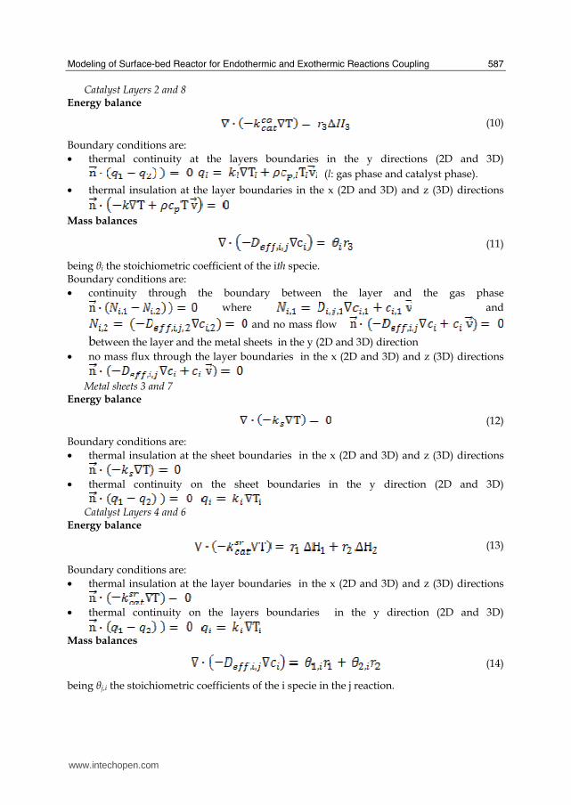
Modeling of Surface-bed Reactor for Endothermic and Exothermic Reactions Coupling
587
Catalyst Layers 2 and 8 Energy balance
(10)
Boundary conditions are bull thermal continuity at the layers boundaries in the y directions (2D and 3D)
(l gas phase and catalyst phase)
bull thermal insulation at the layer boundaries in the x (2D and 3D) and z (3D) directions
Mass balances
(11)
being θi the stoichiometric coefficient of the ith specie Boundary conditions are bull continuity through the boundary between the layer and the gas phase
where and
and no mass flow between the layer and the metal sheets in the y (2D and 3D) direction
bull no mass flux through the layer boundaries in the x (2D and 3D) and z (3D) directions
Metal sheets 3 and 7 Energy balance
(12)
Boundary conditions are bull thermal insulation at the sheet boundaries in the x (2D and 3D) and z (3D) directions
bull thermal continuity on the sheet boundaries in the y direction (2D and 3D)
Catalyst Layers 4 and 6
Energy balance
(13)
Boundary conditions are bull thermal insulation at the layer boundaries in the x (2D and 3D) and z (3D) directions
bull thermal continuity on the layers boundaries in the y direction (2D and 3D)
Mass balances
(14)
being θji the stoichiometric coefficients of the i specie in the j reaction
wwwintechopencom
Recent Advances in Modelling and Simulation
588
Boundary conditions are bull continuity through the boundary between the layer and the gas phase
where and
and no mass flow
between the catalyst layer and the metal sheet in
the y (2D and 3D) direction bull no mass flux through the layer boundaries in the x (2D and 3D) and z (3D) directions
In the balances above the gas densities were calculated using the ideal gas law whereas for catalyst density a constant value was assumed Viscosities and thermal conductivities of the gaseous species refer to the values of the component largely in excess in the specific gas mixtures that is H2O for the steam reforming channel and air for the combustion channels Their dependence of the temperature was excerpted from experimental values from the literature (Perry amp Green (1997)) and included as interpolated functions inside the calculation software To work out heat capacities expressions such as
(15)
were used where A B and C were evaluated by the regression of an expression (Perry amp Green (1997) such as
(16)
The diffusivity coefficients were calculated for a binary mixture between component ith and H2O (in the reforming channel) or air (in the combustion channels) The effective diffusion coefficient inside the catalyst layer is (Perry amp Green (1997)
(17)
where is the catalyst porosity τ the tortuosity and Dij the Knudsen diffusion coefficient and the molecular diffusion coefficient of the ith specie in the jth specie respectively Molecular diffusion coefficients were evaluated using (Perry amp Green (1997))
(18)
where T is the temperature in [K] π the total pressure of the system in [Pa] Mi and Mj the molecular weights of ith and jth species respectively and φi the atomic diffusion volumes characteristic for each component (Perry amp Green (1997)) Knudsen diffusion coefficients were evaluated using (Perry amp Green (1997))
(19)
where Rp is the mean pore radius and T the temperature into the catalyst
wwwintechopencom
Modeling of Surface-bed Reactor for Endothermic and Exothermic Reactions Coupling
589
33 Numerical stuff and reference case simulation
The finite element solution algorithm was completed using COMSOL Multiphysics (Comsol Inc version 33a) Multiphysics modules of incompressible Navier-Stokes convectionndashdiffusion and conductionndashconvection were applied when appropriate to the three-phase domains Meshing parameters were different for the 2D and the 3D FEM schemes In particular in the case of 2D a mapped mesh scheme was employed with rectangular extra fine meshes and edge vertex distribution as follows longitudinal edges 1001 transverse edges 51 (metallic plate) and 101 (catalyst layers and channels) In the case of 3D predefined mesh sizes extra coarse with characteristics listed in Table 3 were employed
Number of degrees of freedom 381162
Number of mesh points 6976
Number of elements 33702
Tetrahedral 33702
Number of boundary elements 12840
Triangular 12840
Number of edge elements 740
Number of vertex elements 24
Minimum element quality 0158
Element volume ratio 0015
Table 3 Mesh Statistics
A reference case with given reactor geometric configuration and operating conditions was chosen to carry out a reference case simulation Other simulations were carried out to explore the influence on the reactor performance of specific geometrical andor operating parameter changes The conditions used in the calculations for the reference case are listed in Table 4 Inlet conditions for the reforming side are similar to those used by Xu and Froment (1989b) but for the total pressure close to atmospheric in our case 29 bar characteristic of industrial operation in the kinetics from Xu amp Froment This because as suggested in the literature (Kolios et al 2004) small-scale hydrogen production which is the potential application for such type of reactor is expected to operate at low pressure This represents a limit of the present work However similar detailed rate equations for the investigated reacting system are not available at ambient pressure in the literature Data reported in Table 4 show that the inlet reforming reaction mixture has a steammethane ratio of 3 and contains trace amounts of CO2 H2 and CO On the methane combustion side the airndashmethane mixture has a 40 air excess with respect to stoichiometric The inlet temperature of both streams is 800 K that is close to that typical of industrial steam reforming The inlet methane mass flow rate in the reforming channel is fixed at 167 cm3s at STP while the inlet methane mass flow rate in the combustion channel is obtained from an overall heat balance The data for reforming catalyst used in the calculations are typical for such a reaction and similar to that used by Xu amp Froment (1989a) for a catalyst containing 152 Ni supported on MgO-αAl2O3
wwwintechopencom
Recent Advances in Modelling and Simulation
590
Table 4 Data used for reference case calculations
Figure 2 Temperature space profiles along the reactor centerline of the reforming channel (solid blue) centerline of the combustion channel (solid red) centerline of the reforming catalyst (dashed blue) and centerline of the combustion catalyst (dashed red)
Gas phase Reforming channel Combustion channels Inlet conditions co-current flow compositions vol H2O 6666 CH4 3333 750 CO2 1 10-3 CO 1 10-3 O2 1943 N2 7307 H2 1 10-3 temperature 800 K 800 K CH4 mass flow rate cm3s (STP) 167 0417 pressure 101 kPa (channel outlet) 101 kPa (channel outlet) channel width m 2 10-3 1 10-3 channel height m 10 10-2 average velocity ms 097 087 channel length m 5 10-2 Catalyst layers thickness (c) μm 200 Average pore radius nm 15 porosity 05 tortuosity 4 Metal plates Thickness m 5 10-4 material aluchrom Thermal conductivity w(m K) Temperature dependent
wwwintechopencom
Modeling of Surface-bed Reactor for Endothermic and Exothermic Reactions Coupling
591
Figure 3 Axial profiles of heat flux in the y direction adjacent to the reforming catalyst in the metallic plate (solid line) in the reforming channel (dotted line)
The catalyst layer density is assumed to be 2300 kgm3 For both type of catalyst layers an average pore radius of 15 nm together with a porosity of 05 and a tortuosity factor of 4 are considered These values are typical for both combustion and reforming catalysts (De Deken et al 1982 Xu amp Froment 1989 b Groppi et al 1995)
4 Results
41 Thermal behaviour
Given the symmetry of the reactor for both 3D and 2D simulations only half of the reactor was simulated by substituting the proper boundary conditions (symmetry) in place of the lacking half Results in simulations performed with the 2D model under the reference case conditions are shown in Figures 2-7 The first aspect to consider is the thermal coupling of steam reforming with catalytic combustion in terms of evolution of both exothermic and endothermic conversion Figure 2 shows the temperature longitudinal profiles on the centerlines of the combustion and the reforming channels and in the combustion and reforming catalysts The profiles are very close each other and they increase from the inlet value of 800 to 914 K at the reactor outlet Therefore the catalytic combustion provides the necessary heat flux to heat up both reaction mixtures and to simultaneously drive the endothermic process A methane conversion at the reactor outlet of 089 for combustion and 074 for reforming are achieved Figure 3 shows the axial profiles of the absolute values of the heat fluxes in the y direction at the boundaries of the reforming catalyst One profile (solid line) is the heat flux from the metallic plate towards the reforming catalyst the other the heat flux from the reforming catalyst to the gas mixture in the reforming channel The two profiles present similar shapes with a maximum at 7 mm and 5 mm from the reactor entrance (distances within which the profiles are increasing) The difference between the profiles represents the heat absorbed by the reforming reaction system (eqs (1) and (2)) The maxima heat fluxes generated and consumed reach values of the order of 105 Wm2 ie 10 Wcm2 that considering the very small temperature gradients (Figure 2) is a very high value with respect to that attainable in industrial practice
wwwintechopencom
Recent Advances in Modelling and Simulation
592
a)
b)
Figure 4 Reactor temperature transverse profiles a at 15 cm from the reactor entrance b at 10 cm from the reactor outlet From 0 to 1 reforming channel From 1 to 12 reforming catalyst From 12 to 17 metallic plate From 17 to 19 combustion catalyst From 19 to 24 combustion channel
A further aspect to be examined is the magnitude of the transverse temperature gradients From Figure 2 it is already evident that the four profiles are very close each other However the transverse temperature gradients can be better analyzed from Figure 4 where the transverse temperature profiles at 15 cm (Figure 4a) from the reactor entrance and at 05 cm (Figure 4b) from the reactor outlet are shown In particular Figure 4a which pertains to the distance from the reactor inlet where the highest transverse temperature gradients develop evidences that the maximum temperature difference between reforming and combustion catalyst is 07 K while the maximum difference between the reforming and combustion channels is less than 10 K although that inside the reforming channel is almost 20 K Much lower differences can be observed close to the reactor outlet Specifically Figure 4b shows that the maximum temperature difference between reforming and combustion catalyst is 01 K that between the reforming and combustion channels is less than 1 K and that inside the reforming channel is almost 2 K As a result the high thermal conductivity of the metallic
wwwintechopencom
Modeling of Surface-bed Reactor for Endothermic and Exothermic Reactions Coupling
593
wall makes possible an efficient heat transfer at a temperature difference of the order of tenths of K With reference to Figure 4 it must be remarked that the value 0 of the transverse coordinate represents the centre of the reactor and the centre of the reforming channel Therefore at that point there is not a physical boundary the heat flux and the momentum flux are both zero and the x component of the gas velocity is maximum On the contrary the value 29 10-3 m of the transverse coordinate represents a solid wall that is the external boundary of the reactor and the boundary of the combustion channel This means that the heat flux is zero both components of the gas velocity are zero and the momentum flux is not zero This is one of the reasons because for the same distance in the transverse direction (y) the gas phase temperature difference in the reforming channel results always larger than that in the combustion channel (Figures 2 4a and 4b)
42 Mass transfer and chemical reactions
The concentration on the centerline of the reforming channel of the various species involved in the reactions occurring within the reforming catalyst are shown in Figure 5 This yields an overall picture of the reactor performance The hydrogen concentration steadily increases from the initial value to about 9 molm3 resulting the most abundant component in the exit gas mixture The ratio between the hydrogen concentration and CO concentration is very high (about 9)
Figure 5 Axial profiles of species concentrations on the centerline of the reforming channel
One important aspect to determine is the effect of interphase mass transport resistance Figure 6a shows the methane concentration axial profiles on the centerlines of the combustion channels and of the combustion catalyst while Figure 6b shows the correspondent profiles for the reforming section of the reactor From these Figures the differences between the channel and the catalyst profiles in each section yield a measure of the resistance to the interphase transport As expected in the combustion section the axial methane concentration profiles both in the channel and in the catalyst show an exponentially decreasing trend which reflects the relatively simple kinetics of the reaction In contrast a more complex trend is shown by the axial methane concentration profile in the catalyst because of the non linearity of the kinetics and the simultaneous occurrence of two
wwwintechopencom
Recent Advances in Modelling and Simulation
594
reactions (eqs (1) and (2)) Another aspect to examine is the size of the concentration gradients in the transverse direction These can be appreciated from Figure 7 where the transverse methane concentration profiles at 15 cm from the reactor inlet and at 05 cm from the reactor outlet are shown In particular the first profile which pertains to the distance from the reactor inlet where the highest transverse temperature gradients develops evidences that the gradients inside the reforming and the combustion channels are negligible with respect to the gradients in the catalyst phase The order of magnitude of these latter range from 105 molm4 close to the reactor inlet to 104 molm4 in the remaining part of the reforming catalyst and in all the combustion catalyst too
a)
b)
Figure 6 Axial methane concentration profiles along the reactor (a) solid line combustion channel dashed line combustion catalyst (b) solid line reforming channel dashed line reforming catalyst
wwwintechopencom
Modeling of Surface-bed Reactor for Endothermic and Exothermic Reactions Coupling
595
Figure 7 Methane concentration transverse profiles at 15 cm from the reactor entrance (solid line) and at 10 cm from the reactor outlet (dashed line) From 0 to 1 reforming channel From 1 to 12 reforming catalyst From 12 to 17 metallic plate From 17 to 19 combustion catalyst From 19 to 24 combustion channel
43 Methane concentration in the combustion channel
A basic requirement of the system in the object which is thought to be used for energy feeding of portable electric devices should be the complete reliability with respect to possible uncontrolled rises in temperature or even to a possible explosion hazard In this view the coordination between exothermic and endothermic reaction rates appears fundamental However even in the case such a coordination occurs the possible progress of the combustion reaction in the homogeneous phase may represent an hazard In addition if the concentration of the reacting mixture entering the combustion channel is within the flammability limits and the temperature becomes high enough it could ignite before the reactor inlet Therefore for safety purposes the occurrence of the exothermic reaction here represented by the methane combustion in the homogeneous phase should be avoided A possible way to make the system of hydrogen generation intrinsically safe is to feed the combustion mixture at a methane concentration below the LEL (lower explosivity limit) Considering that at STP the LEL of methane in air is about 5 vol that the autoignition temperature for airmethane mixtures is around 900 K the extimated LEL of methane in air at such a temperature should be about 3 vol (Crowl amp Louvar (2002)) Therefore a safe operating concentration should be about 3 vol To this purpose in this work beside those carried out under the conditions considered in the reference case other simulations were effected for which for a given methane mass flow rate its concentration at the combustion channel inlet was kept below 3 vol In this way the system is intrinsically safe because the reacting mixture cannot ignite spontaneously In addition the simulation becomes more realistic the contribution to the methane combustion of the homogeneous phase being really absent as implicitly hypothesized in this work
wwwintechopencom
Recent Advances in Modelling and Simulation
596
Figure 8 Temperature distribution over the boundaries of the 3D reactor
The comparison of results of runs performed under these conditions with those effected under the conditions of the reference case are reported in the following when analyzing the influence of various parameters on the reactor performance These simulations are labeled in the paper as n-expl in contrast to the others that are recalled as expl
44 Comparison between 2D and 3D results
For given operating conditions some simulations were carried out in both 2D and 3D geometry In principle a plane 2D geometry represents a slice of the reactor where the z dimension is greatly prevalent with respect to the y dimension Actually the model reactor has not such characteristics the length in the z dimension being 10 mm that is only 5 times the reforming channel width This means that the boundary effects due to the presence of the boundary walls in the z direction may have a significant influence on the velocity temperature and species concentration profiles that certainly influence the overall reactor performance Figures 8 shows the temperature distribution over the boundaries of the 3D reactor obtained under operating conditions of the reference case From this Figure the effect of the boundaries along the z direction appears evident
wwwintechopencom
Modeling of Surface-bed Reactor for Endothermic and Exothermic Reactions Coupling
597
Figure 9 Temperature space profiles along the reactor calculated with the 2D model (for the legend see caption to Figure 2)
Figure 10 Temperature space profiles along the reactor calculated with the 3D model (for the legend see caption to Figure 2)
Figures 9 and 10 show the reactor temperature longitudinal profiles on the centerlines of the combustion and the reforming channels and on the centerline of the combustion and reforming catalysts in the case of 2D and 3D geometry models respectively Both were calculated under the same operating conditions ie same inlet mass flow rates and compositions of the reference case (expl) but inlet temperature of 900 K In the case of the
wwwintechopencom
Recent Advances in Modelling and Simulation
598
3D simulation (Figure 10) the temperature profiles are those lying over a xy plane intersecting the reactor in the middle of its height along z The two sets of profiles appear quite similar the temperatures in the combustion section (catalyst and channel) are always slightly higher than the corresponding ones in the reforming section However a closer inspection reveals some significant differences In the 2D case the temperature after an initial slow growth increases steadily from 900 K at the reactor inlet up to 965 K at the reactor outlet while in the other case it grows faster reaches 960 K at 60 of the reactor length and remains constant up to the outlet Another difference is represented by the larger transverse temperature gradients of the 3D case with respect to 2D In the 2D case they are comparable with those observed in Figure 2 for the reference case while in the 3D case they are almost double This is true for all combinations ie catalyst-catalyst catalyst-channel and channel-channel On the whole the 3D case shows a faster progress of the reactions with consequent need for faster heat transfer These differences in the thermal behaviour between 2D and 3D simulations persist when the comparison is extended to other operating conditions and in addition they reflect the better overall performance of the 3D reactor with respect to the 2D as can be seen by the following discussion The quantitative comparison between the 2D and 3D simulations was made with respect to the main results ie the methane conversion in both the combustion and the steam reforming channels as obtained from equation 5 Further beside the methane conversions other parameters are employed ie a) the gas hourly space velocities GHSV in the combustion and steam reforming sides of the reactor calculated as ratio between gas flow rates at the reactor inlet temperature and volume of catalyst b) the maximum temperature reached in the reactor c) the mean gas residence time trm in both the combustion and the reforming channel calculated as ratio between the gas flow rates at the reactor inlet temperature and the volume of the channel and d) the hydrogen yield φH2 evaluated as ratio between the amounts of methane reacted and hydrogen produced GHSV and trm were useful to allow the comparison of simulations carried out by changing the catalyst volume or the channel width as discussed later Results of simulations carried out with the 2D and 3D models under various operating conditions are reported in Table 5 Those referring to the operating conditions of the reference case are listed in the first two rows of such a Table The other operating conditions are i) same inlet temperature of the reference case but different methane concentration in the combustion channel (3rd and 4th rows of Table 5) and ii) different inlet temperatures for the two conditions above (5th-8th rows of Table 5) Focusing the comparison on the results of the simulations in 2D and 3D with the same operating conditions it appears that in general the methane conversions at the reactor outlet calculated with the 2D geometry in both the combustion and reforming channels are lower than the correspondent in 3D geometry but in one case (Xch4-sr 3rd and 4th rows of the Table) This finding reflects the differences in the thermal behaviour discussed above In any case such conversions differ by less than 10 but in the last two rows of the Table where the differences are larger It is worth noting however that even in this case the values of the conversions are congruent with the overall results of the simulation For instance the lower value of Xch4-co in the 2D with respect to the correspondent in 3D results in a lower value of Xch4-sr and in a lower maximum temperature reached in the reactor
wwwintechopencom
Modeling of Surface-bed Reactor for Endothermic and Exothermic Reactions Coupling
599
Geometry Tin K
Xch4-co Xch4-sr Tmax K Trm-co ms
Trm-sr ms
GHSVco h-1
GHSVsr h-1
φH2
2D expl 800 089 074 914 0057 0026 314840 702884 329
3D expl 800 096 077 914 0057 0026 314840 702884 333
2D n-expl 800 036 045 827 0020 0026 900588 702884 344
3D n-expl 800 040 041 828 0020 0026 900588 702884 356
2D expl 900 095 090 965 0051 0023 354194 790745 305
3D expl 900 099 093 960 0051 0023 354194 790745 300
2D n-expl 900 049 069 900 0018 0023 1013162 790745 322
3D n-expl 900 068 079 920 0018 0023 1013162 790745 318
Table 5 Comparison of 2D and 3D results obtained under the same operating conditions
For what concerns the hydrogen yield focusing again the comparison on the results of the simulations in 2D and 3D at the same operating conditions data show that φH2rsquos obtained with the 2D geometry model are lower than that in 3D model but in one case (7th and 8th row of Table 5) It is worth noting that φH2=3 would be the stoichiometric value if reaction (1) were the only occurring in the reforming catalyst so that the amount exceeding 3 is due to the contribution of reaction (2) Data in Table 5 also shows the influence on the reactor performance of temperature and inlet methane concentration in the combustion channel In the case of inlet temperature of 900 K and methane concentration within the explosivity limits (case referring to results in Figures 9 and 10) the methane conversion is practically 1 (3D model) for the combustion reaction and very high for the reforming reactions However under these conditions the hydrogen yield is the lowest In contrast when the highest hydrogen yield is reached the lowest methane conversion is achieved Similar considerations can be done for the other results in the Table so that a general trend can be drawn from such results The higher the maximum temperature reached in the reactor the higher the methane conversions and the lower the hydrogen yield
45 Influence of the channels width
The reactor thermal behaviour and performance was studied for different channels width Wc at constant inlet flow rates of the reaction mixtures Runs were also carried out by keeping constant the mean inlet velocities of reaction mixtures The variation range for the combustion channels width Wc-co was 1-15 mm and for the reforming channel width Wc-sr 2-3 mm All other parameters were kept at their reference case values Keeping constant the inlet mass flow rates and altering the channel width results in modifying the inlet velocities in the reactor and consequently the mean residence time (trm) of the gases in the channels but the GHSVrsquos do not change The results in terms of methane conversions in the combustion and reforming channels are reported in Table 6 for the reference cases (3rd and 4th row in Table) and for cases where the methane concentration in the combustion channels were below the LEL (1st and 2nd row) At constant mass flow rates the influence of the channel width or better of trm appears negligible under n-expl conditions with a slight
wwwintechopencom
Recent Advances in Modelling and Simulation
600
prevalence of the reactor with narrower channels and weak under expl conditions with in contrast better performance for the reactor with wider channels Therefore it is not possible to draw conclusions
Wc-sr mm
Tin K
Xch4 -
co Xch4-sr
Tmax K
trm-co ms
trm-sr ms
GHSVco h-1
GHSVsr h-1
2 n-expl 800 036 045 827 0020 0026 900588 702884
3 n-expl 800 034 044 819 0030 0038 900588 702884
2 expl 800 089 074 914 0057 0026 314840 702884
3 expl 800 092 081 940 0086 0038 314840 702884
Vcost- 3 n-expl 800 022 033 800 0020 0026 1350882 1054327
Table 6 Comparison between reactor performance as a function of channel width
Unlike the previous case where inlet flow rates were kept constant an increase in channel width keeping the mean gas velocity and the value of trm constants affects significantly the outlet conversions In this case the amount of reactants flowing through the reactor per unit catalyst volume and then GHSV increases (compare 1st and 5th rows in Table 5) Increasing channel widths from their reference case value (Wc-sr = 2 mm and Wc-co= 1) at constant gas inlet velocity leads to methane conversion reduction because a) the catalyst amount becomes insufficient for the amount of reactants fed in the reactor and b) the external mass transfer resistances play a stronger role The overall reaction heat fluxes remain the same as channel width increases leaving a similar amount of sensible heat to be used for heating up larger amounts of reactants This results in lower temperatures along the reactor
46 Influence of catalyst thickness
The influence of catalyst thickness c on the reactor behaviour was studied by keeping constant the reactants mass flow rates The reactor operation was simulated for three values of catalyst thickness ie 200 100 and 50 microm while keeping all the other parameters at their reference case values but for what concerns the inlet methane concentration in the combustion channel that was at non explosive level This with respect to the reference case corresponds to decreasing GHSV of factors 2 and 4 respectively Changes in the catalyst thickness influence considerably both thermal behaviour and outlet conversions As above the comparison is made through the methane conversions achieved in the two cases both in the steam reforming and in the combustion channels The results are reported in Table 7 It is evident that the loss of performance due to a decrease of 50 of c from 200 to 100 μm is almost negligible This is mainly due to the conservative parameters used for defining the catalyst layer characteristics (ie mean pore radius and tortuosity) that results in a very impervious path for diffusing gases However when c is further decreased methane conversion both in the combustion and in the reforming section significantly decrease The hydrogen yield does not change too much within the limits of the three cases analyzed
wwwintechopencom
Modeling of Surface-bed Reactor for Endothermic and Exothermic Reactions Coupling
601
δc μm
Tin K Xch4 -co Xch4-sr Tmax Ktrm-co ms
trm-sr ms
GHSVco h-1
GHSVsr h-1
φH2
200 n-expl 800 036 045 827 0020 0026 900588 702884 344
100 n-expl 800 035 045 827 0020 0026 1801176 1405768 344
50 n-expl 800 027 038 800 0020 0026 3602352 2811536 342
Table 7 Comparison between reactor performance as a function of catalyst thickness
5 Discussion
As seen in the previous section (4) there are several operating parameters that influence the performances of the system They are typical of reacting systems and can be summarized as GHSVrsquos tmrrsquos and inlet gas temperatures The particularity of the present case is the simultaneous occurrence of two coupled reactions one exothermic and the other endothermic in which the extent of the second depends on the extent (heat produced) of the first and the effectiveness of the heat transferred In addition the coupling of the two reactions does not exclude to have for each set of values of the mentioned parameters pertaining to one reaction several sets of parameters for the other reaction This makes the system quite complex and difficult to analyze However some general considerations can be drawn
Figure 11 Methane conversions in the combustion and reforming sides of the reactor as a function of GHSV for various operating conditions available in Table 6 and 7
The first is that as expected GHVS plays a key role in determining the reactor performances although this is supported by only a part of the data For instance data in Table 7 pertaining to simulations of the influence of such a parameter carried out by changing GHSV in the same way for both sections of the reacting system shows a clear effect of GHSV the reactor
0 1000000 2000000 3000000 4000000
GHSV h-1
02
04
06
08
1
XC
H4
-co a
nd
XC
H4
-sr -
data from Table 7 comb side
data from Table 7 refor side
data from Table 6 comb side
data from Table 6 refor side
wwwintechopencom
Recent Advances in Modelling and Simulation
602
performance decreases as GHSV increases on both sides of the reactor Such an influence does not appear strong the conversion change being about 20 against GHSV variations of a factor 4 (Figure 11) The influence of GHSV is more evident from data in Table 6 pertaining to simulations of the influence of tmr In fact also in this case a clear trend appears and the influence even though in the same direction of the previous case appears much stronger since with respect to a GHSV change of about 20 the methane conversion varies by a factor 4 (Figure 11) Such a strong influence is due to the combined effect of tmr especially on the combustion side of the reactor (cfr Table 6) Instead for data in Table 5 pertaining to simulations of the reliability of 2D and 3D models and the effect of gas inlet temperature it is not possible to highlight a clear influence The comparison between the results obtained with the 2D and 3D models under the same operating conditions have evidenced differences in the performance of the reactor not large but significant When we move from 2D to 3D models such differences result in an increase from 5 to 20 of both Xch4-co and Xch4-sr which reflects a different thermal behavior of the reacting system and influence also the hydrogen yield It is worth noting that the computation time required in the two cases is very different Specifically using an HP xw8400workstation equipped with 2 Xeon processors and 4 GB of RAM a 2D simulation takes on the average about 20 minutes with respect to 50-60 hours necessary in the 3D case It is impossible by now to establish which is the more correct or the more reliable In particular it should be assessed if 2D simulations are suitable for purpose of reactor design and experimental data interpretation The answer should come from the comparison of the results of such simulations with experimental data obtained with a real reactor geometrically comparable operated under conditions as much as similar to those fixed for the simulations This represents argument for coming work of the authors Further interesting aspects to be studied are the simulation of unsteady-state conditions and specifically of the system start-up and of the system response to small changes in the gas feeding flow rates and temperatures
6 Conclusions
Methane steam reforming coupled with methane catalytic combustion by means of indirect heat transfer in a surface-bed catalytic reactor was studied by 2D and 3D models The reactor consists of a central reforming channel and two lateral combustion channels A reference case for what concerns operating conditions and reactor geometry was chosen and its simulation was carried out Changes of reactor performance as consequence of operating parameters and reactor geometry variations were analyzed with respect to the reference case The simulation showed that suitable amount of fuel and adequate catalyst activity in the combustion channel can provide enough heat to simultaneously heat up the reaction mixture and drive the endothermic process The proximity between the heat source and the heat sink increases the efficiency of heat transfer resulting in transverse temperature gradients do not exceeding generally 07 K across the metallic wall and 20 K across the gas in the channel Decrease of transverse temperature differences and intraphase mass transfer resistances have the global effect of reducing the reactor dimension and the catalyst amount The influence of channels width and catalyst layer thickness on reactor behaviour was also studied At constant inlet flow rates changes of channel width in the range 1ndash2 mm do not introduce significant differences in the reactor performance Rather small differences in the
wwwintechopencom
Modeling of Surface-bed Reactor for Endothermic and Exothermic Reactions Coupling
603
catalyst axial temperature profiles and outlet methane conversions are observed In contrast altering the channel width at constant inlet velocities has strong influence Larger channel width results in lower conversion and smoother axial temperature profiles Intraphase resistances are present even for catalyst thickness of micrometers for both reforming and combustion processes Increasing GHSV that is the inlet flow ratecatalyst volume ratio leads to lower outlet conversions Due to different effect of catalyst layer thickness on reforming and combustion channels there are significant changes in the reactor temperature profile Results indicate that steam reforming of methane in a surface-bed reactor is feasible provided that mass flow rates channels width catalyst loadings and thickness are properly designed
7 Notation
cp specific heat J(mol K) c concentration molm3 Deff effective diffusion coefficient m2s D molecular diffusion coefficient m2s GHSV gas hourly space velocity h-1 k thermal conductivity W(m K) or reaction rate constant Ke equilibrium constant M molecular weight kgmol LEL lower explosivity limit vol
unit vector perpendicular to the flux surface
N molar flux at the boundary mol(m2 s) p partial pressure bar P total pressure bar q thermal flux at the boundary J(m2 s) r reaction rate various dimensions (see eqs 1rsquo 2rsquo and 3rsquo) Rp catalyst pore radius nm STP standard temperature and pressure (298 K and 101 103 Pa) t time s T temperature K ts transverse surface ux Velocity component on the x coordinate
velocity vector
v normal component of velocity at the channel ingress x axial coordinate m X conversion y transverse coordinate m Wc distance between the reactor plates m z vertical coordinate m Greek letters ΔH0r heat of reaction at reference state conditions KJmol c catalyst thickness μm catalyst porosity φ atomic diffusion volume or chemical reaction yield
wwwintechopencom
Recent Advances in Modelling and Simulation
604
θ stoichiometric coefficient ρ density kgm3 τ catalyst tortuosity
Subscripts and superscripts cat catalyst co combustion CH4 methane H2 hydrogen in inlet i chemical species j channel k reaction l phase rm mean residence s metal sheet sr steam reforming 0 channel ingress 1 reforming reaction 2 water gas shift reaction 3 combustion reaction
8 Acknowledgements
The authors gratefully acknowledge the financial support of MIUR under grant PRIN ndeg 2006094333004
9 References
Akers WW amp Camp DP (1955) Kinetics of the methanendashsteam reaction AIChE Journal Vol 1 471ndash475 ISSN0001-1541
Allen DW Gerhard ER amp Likins Jr MR (1975) Kinetics of the MethanendashSteam Reaction Ind Eng Chem Proc Des Dev Vol 14 No 3 256-259 ISSN0196-4305
Aparicio L (1997) Transient Isotopic Studies and Microkinetic Modeling of Methane Reforming over Nickel Catalysts Journal of Catal Vol 165 No 2 262-274 ISSN 0021-9517
Avci AK Trimm DL amp İlsen Oumlnsan Z (2001) Heterogeneous reactor modeling for simulation of catalytic oxidation and steam reforming of methane Chem Eng Sci Vol 56 No 2 641-649 ISSN0009-2509
Bridger GW (1980) The steam reforming of hydrocarbons Catalysis Vol 3 39-69 ISSN0140-0568
Cao C Wang Y amp Rozmiarek RT (2005) Heterogeneous reactor model for steam reforming of methane in a microchannel reactor with microstructured catalysts Catal Today Vol 110 No 1-2 92ndash97 ISSN 0920-5861
Craciun R Shereck B amp Gorte RJ (1998) Kinetic studies of methane steam reforming on ceria-supported Pd Catal Lett Vol 51 No 3ndash4 149-153 ISSN 1011-372x
wwwintechopencom
Modeling of Surface-bed Reactor for Endothermic and Exothermic Reactions Coupling
605
Crowl DA amp Louvar JF (2002) Chemical Process Safety fundamentals with applications 2nd ed Prentice Hall PTR Upper Saddle River NJ USA ISBN 0-13mdash018176-5
De Deken J C Devos E F amp Froment G F (1982) Steam reforming of natural gas Intrinsic kinetics diffusional influences and reactor design ACS Symposium Series 196 181ndash197 ISSN0097-6156
Ehrfeld W amp Hessel V Lowe H (2000) Microreactor Wiley-VCH Verlag GmbH D-69469 ISBN Weinheim Germany
Gosiewski K (2001) Simulations of non-stationary reactors for catalytic conversion of methane to synthesis gas Chem Eng Sci Vol 56 No 4 1501-1510 ISSN
Groppi G Belloli A Tronconi E Forzatti P (1995) A comparison of lumped and distributed models of monolith catalytic combustors Chem Eng Sci Vol 50 No 17 2705ndash2715 ISSN0009-2509
Holladay JD Wang Y amp Jones E (2004) Review of Developments in Portable Hydrogen Production Using Microreactor Technology Chem Rev Vol 104 No 10 4767-4790 ISSN 0009-2665
Hou K amp Hughes R (2001) The kinetics of methane steam reforming over a Ni-Al2O3 catalyst Chem Eng Journal Vol 82 No 1-3 311-328 ISSN 1385-8947
Jamal Y amp Wyszynski M L (1994) On-board generation of hydrogen-rich gaseous fuels a review Int J of Hydrogen Energy Vol 19 No 7 557-572 ISSN 0360-3199
Jensen KF (2001) Microreaction engineering is small better Chem Eng Sci Vol 56 No 2 293-303 ISSN0009-2509
Kolios G Gritsch A Glo1ckler B amp Sorescu G (2004) Novel Reactor Concepts for Thermally Efficient Methane Steam Reforming Modeling and Simulation Ind Eng Chem Res Vol 43 No 16 4796-4808 ISSN0888-5885
Kruger P Blakeley J amp Leaver J (2003) Potential in New Zealand for use of hydrogen as a transportation fuel Int J of Hydrogen Energy Vol 28 No 8 795ndash802 ISSN 0360-3199
Kvamsdal HM Svendsen HF Hertzberg T amp Olsvik O (1999) Dynamic simulation and optimization of a catalytic steam reformer Chem Eng Sci Vol 54 No 13-14 2697-2706 ISSN0009-2509
Lerer M Duic N Alves LM amp Carvalho MG (2006) H2 RES energy planning tool for increasing the penetration of renewable energy sources in island energy supply In New and Renewable Technologies for Sustanaible Development MG Carvalho and NH Afgan (Ed s) 15-30 World Scientific ISBN 10 981-270-505-8 Singapore
Lerou JJ amp Ng KM (1996) Chemical reaction engineering A multiscale approach to a multiobjective task Chem Eng Sci Vol 51 No 10 1595-1614 ISSN0009-2509
Lincoln SF (2006) Challenged Earth ch7 Imperial College Press ISBN 1-86094-526-0 London
Loffler D G Faz C F Sokolovskii V amp Iglesia E (2002) Catalytic separator plate reactor and method of catalytic reforming of fuel to Hydrogen PCT Int Appl WO 0228769 A2
Luna C amp Becerra AM (1997) Kinetics of methane steam reforming on a Ni on alumina-titania catalyst React Kinet Catal Lett Vol 61 No 2 369-374 ISSN 0133-1736
Marschner F Renner HJ amp Boll W (2005) Electronic Encyclopedia Release 2005 7th ed in Ullmannrsquos Encyclopedia of Industrial Chemistry M Bohnet et al (Eds) Vol a12 John Wiley amp Sons ISBN-13 978-3-527-30385-4
wwwintechopencom
Recent Advances in Modelling and Simulation
606
Moore R B amp Raman V (1998) Hydrogen infrastructure for fuel cell transportation Int J of Hydrogen Energy Vol 23 No 7 617-620 ISSN 0360-3199
Perry RH amp Green DW (1999) Perrys Chemical Engineers Handbook (7th Ed) McGraw-Hill ISBN 0-07-049841-5
Robbins F A Zhu H amp Jackson GS (2003) Transient modeling of combined catalytic combustionCH4 steam reformng Catal Today Vol 83 No 1-4 141ndash156 ISSN 0920-5861
Rostrup-Nielsen JR Christiansen LJ amp BakHansen JH (1988) Activity of steam reforming catalysts Role and assessment Appl Catal Vol 43 No 2 287-303 ISSN0166-9834
Rostrup-Nielsen JR (1995) Innovation and the catalytic process industry - the science and challenge Chem Eng Sci Vol 50 No 24 4061-4071 ISSN0009-2509
Rostrup-Nielsen JR Dybkjaer I amp Coulthard GRG (2001) Topical Conf Proc AIChE Spring National Meeting Houston TX April Paper No 1
Rostrup-Nielsen JR (2004) Fuels and Energy for the Future The Role of Catalysis Catal Rev - Science and Engineering Vol 46 No 3ndash4 247-270 ISSN0161-4940
Schubert K Brandner J Fichtner M Linder G Schyhulla U amp Wenka A (2001) Microstructure devices for applications in thermal and chemical process engineering Microscale Thermophys Eng Vol 5 No 1 17-39 ISSN1089-3954
Tronconi E amp Groppi G (2000) A study on the thermal behavior of structured plate-type catalysts with metallic supports for gassolid exothermic reactions Chem Eng Sci Vol 55 Issue 24 December 6021-6036 ISSN0009-2509
Wang Y Johnson BR Cao C Chin Y Rozmiarek RT Gao Y Tonkovich AL (2005) Engineered catalysts for microchannel reactor applications In Microreactor Technology and Process Intensification Y Wang J Holladay (Eds) 65-73 ACS Symposium Series Vol 914 ISBN-13 9780841239234
Xu J amp Froment GF (1989a) Methane steam reforming II Diffusional limitations and reactor simulation AIChE Journal Vol 35 No 1 97-103 ISSN0001-1541
Xu J amp Froment GF (1989b) Methane steam reforming methanation and water-gas shift I Intrinsic kinetics AIChE Journal Vol 35 No 1 88-96 ISSN0001-1541
Zanfir M amp Gavriilidis A (2003) Catalytic Combustion Assisted Methane Steam Reforming Chem Eng Sci Vol 58 No 17 3947ndash 3960 ISSN0009-2509
wwwintechopencom
Modelling and SimulationEdited by Giuseppe Petrone and Giuliano Cammarata
ISBN 978-3-902613-25-7Hard cover 688 pagesPublisher I-Tech Education and PublishingPublished online 01 June 2008Published in print edition June 2008
InTech EuropeUniversity Campus STeP Ri Slavka Krautzeka 83A 51000 Rijeka Croatia Phone +385 (51) 770 447 Fax +385 (51) 686 166wwwintechopencom
InTech ChinaUnit 405 Office Block Hotel Equatorial Shanghai No65 Yan An Road (West) Shanghai 200040 China
Phone +86-21-62489820 Fax +86-21-62489821
This book collects original and innovative research studies concerning modeling and simulation of physicalsystems in a very wide range of applications encompassing micro-electro-mechanical systems measurementinstrumentations catalytic reactors biomechanical applications biological and chemical sensorsmagnetosensitive materials silicon photonic devices electronic devices optical fibers electro-microfluidicsystems composite materials fuel cells indoor air-conditioning systems active magnetic levitation systemsand more Some of the most recent numerical techniques as well as some of the software among the mostaccurate and sophisticated in treating complex systems are applied in order to exhaustively contribute inknowledge advances
How to referenceIn order to correctly reference this scholarly work feel free to copy and paste the following
Salvatore Vaccaro and Paolo Ciambelli (2008) Modeling of Surface-bed Reactor for Endothermic andExothermic Reactions Coupling Modelling and Simulation Giuseppe Petrone and Giuliano Cammarata (Ed)ISBN 978-3-902613-25-7 InTech Available fromhttpwwwintechopencombooksmodelling_and_simulationmodeling_of_surface-bed_reactor_for_endothermic_and_exothermic_reactions_coupling
copy 2008 The Author(s) Licensee IntechOpen This chapter is distributedunder the terms of the Creative Commons Attribution-NonCommercial-ShareAlike-30 License which permits use distribution and reproduction fornon-commercial purposes provided the original is properly cited andderivative works building on this content are distributed under the samelicense
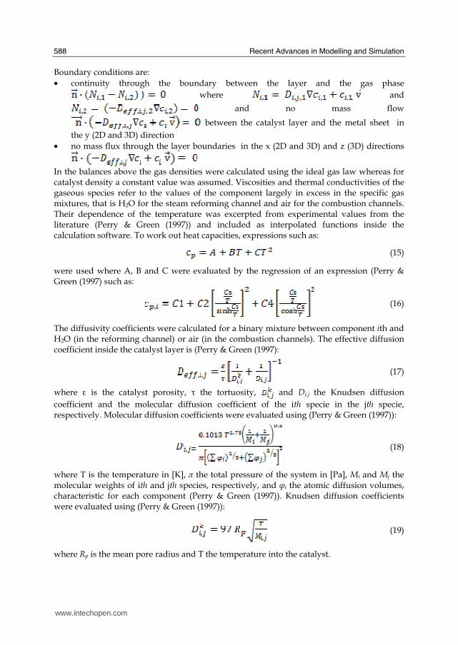
Recent Advances in Modelling and Simulation
588
Boundary conditions are bull continuity through the boundary between the layer and the gas phase
where and
and no mass flow
between the catalyst layer and the metal sheet in
the y (2D and 3D) direction bull no mass flux through the layer boundaries in the x (2D and 3D) and z (3D) directions
In the balances above the gas densities were calculated using the ideal gas law whereas for catalyst density a constant value was assumed Viscosities and thermal conductivities of the gaseous species refer to the values of the component largely in excess in the specific gas mixtures that is H2O for the steam reforming channel and air for the combustion channels Their dependence of the temperature was excerpted from experimental values from the literature (Perry amp Green (1997)) and included as interpolated functions inside the calculation software To work out heat capacities expressions such as
(15)
were used where A B and C were evaluated by the regression of an expression (Perry amp Green (1997) such as
(16)
The diffusivity coefficients were calculated for a binary mixture between component ith and H2O (in the reforming channel) or air (in the combustion channels) The effective diffusion coefficient inside the catalyst layer is (Perry amp Green (1997)
(17)
where is the catalyst porosity τ the tortuosity and Dij the Knudsen diffusion coefficient and the molecular diffusion coefficient of the ith specie in the jth specie respectively Molecular diffusion coefficients were evaluated using (Perry amp Green (1997))
(18)
where T is the temperature in [K] π the total pressure of the system in [Pa] Mi and Mj the molecular weights of ith and jth species respectively and φi the atomic diffusion volumes characteristic for each component (Perry amp Green (1997)) Knudsen diffusion coefficients were evaluated using (Perry amp Green (1997))
(19)
where Rp is the mean pore radius and T the temperature into the catalyst
wwwintechopencom
Modeling of Surface-bed Reactor for Endothermic and Exothermic Reactions Coupling
589
33 Numerical stuff and reference case simulation
The finite element solution algorithm was completed using COMSOL Multiphysics (Comsol Inc version 33a) Multiphysics modules of incompressible Navier-Stokes convectionndashdiffusion and conductionndashconvection were applied when appropriate to the three-phase domains Meshing parameters were different for the 2D and the 3D FEM schemes In particular in the case of 2D a mapped mesh scheme was employed with rectangular extra fine meshes and edge vertex distribution as follows longitudinal edges 1001 transverse edges 51 (metallic plate) and 101 (catalyst layers and channels) In the case of 3D predefined mesh sizes extra coarse with characteristics listed in Table 3 were employed
Number of degrees of freedom 381162
Number of mesh points 6976
Number of elements 33702
Tetrahedral 33702
Number of boundary elements 12840
Triangular 12840
Number of edge elements 740
Number of vertex elements 24
Minimum element quality 0158
Element volume ratio 0015
Table 3 Mesh Statistics
A reference case with given reactor geometric configuration and operating conditions was chosen to carry out a reference case simulation Other simulations were carried out to explore the influence on the reactor performance of specific geometrical andor operating parameter changes The conditions used in the calculations for the reference case are listed in Table 4 Inlet conditions for the reforming side are similar to those used by Xu and Froment (1989b) but for the total pressure close to atmospheric in our case 29 bar characteristic of industrial operation in the kinetics from Xu amp Froment This because as suggested in the literature (Kolios et al 2004) small-scale hydrogen production which is the potential application for such type of reactor is expected to operate at low pressure This represents a limit of the present work However similar detailed rate equations for the investigated reacting system are not available at ambient pressure in the literature Data reported in Table 4 show that the inlet reforming reaction mixture has a steammethane ratio of 3 and contains trace amounts of CO2 H2 and CO On the methane combustion side the airndashmethane mixture has a 40 air excess with respect to stoichiometric The inlet temperature of both streams is 800 K that is close to that typical of industrial steam reforming The inlet methane mass flow rate in the reforming channel is fixed at 167 cm3s at STP while the inlet methane mass flow rate in the combustion channel is obtained from an overall heat balance The data for reforming catalyst used in the calculations are typical for such a reaction and similar to that used by Xu amp Froment (1989a) for a catalyst containing 152 Ni supported on MgO-αAl2O3
wwwintechopencom
Recent Advances in Modelling and Simulation
590
Table 4 Data used for reference case calculations
Figure 2 Temperature space profiles along the reactor centerline of the reforming channel (solid blue) centerline of the combustion channel (solid red) centerline of the reforming catalyst (dashed blue) and centerline of the combustion catalyst (dashed red)
Gas phase Reforming channel Combustion channels Inlet conditions co-current flow compositions vol H2O 6666 CH4 3333 750 CO2 1 10-3 CO 1 10-3 O2 1943 N2 7307 H2 1 10-3 temperature 800 K 800 K CH4 mass flow rate cm3s (STP) 167 0417 pressure 101 kPa (channel outlet) 101 kPa (channel outlet) channel width m 2 10-3 1 10-3 channel height m 10 10-2 average velocity ms 097 087 channel length m 5 10-2 Catalyst layers thickness (c) μm 200 Average pore radius nm 15 porosity 05 tortuosity 4 Metal plates Thickness m 5 10-4 material aluchrom Thermal conductivity w(m K) Temperature dependent
wwwintechopencom
Modeling of Surface-bed Reactor for Endothermic and Exothermic Reactions Coupling
591
Figure 3 Axial profiles of heat flux in the y direction adjacent to the reforming catalyst in the metallic plate (solid line) in the reforming channel (dotted line)
The catalyst layer density is assumed to be 2300 kgm3 For both type of catalyst layers an average pore radius of 15 nm together with a porosity of 05 and a tortuosity factor of 4 are considered These values are typical for both combustion and reforming catalysts (De Deken et al 1982 Xu amp Froment 1989 b Groppi et al 1995)
4 Results
41 Thermal behaviour
Given the symmetry of the reactor for both 3D and 2D simulations only half of the reactor was simulated by substituting the proper boundary conditions (symmetry) in place of the lacking half Results in simulations performed with the 2D model under the reference case conditions are shown in Figures 2-7 The first aspect to consider is the thermal coupling of steam reforming with catalytic combustion in terms of evolution of both exothermic and endothermic conversion Figure 2 shows the temperature longitudinal profiles on the centerlines of the combustion and the reforming channels and in the combustion and reforming catalysts The profiles are very close each other and they increase from the inlet value of 800 to 914 K at the reactor outlet Therefore the catalytic combustion provides the necessary heat flux to heat up both reaction mixtures and to simultaneously drive the endothermic process A methane conversion at the reactor outlet of 089 for combustion and 074 for reforming are achieved Figure 3 shows the axial profiles of the absolute values of the heat fluxes in the y direction at the boundaries of the reforming catalyst One profile (solid line) is the heat flux from the metallic plate towards the reforming catalyst the other the heat flux from the reforming catalyst to the gas mixture in the reforming channel The two profiles present similar shapes with a maximum at 7 mm and 5 mm from the reactor entrance (distances within which the profiles are increasing) The difference between the profiles represents the heat absorbed by the reforming reaction system (eqs (1) and (2)) The maxima heat fluxes generated and consumed reach values of the order of 105 Wm2 ie 10 Wcm2 that considering the very small temperature gradients (Figure 2) is a very high value with respect to that attainable in industrial practice
wwwintechopencom
Recent Advances in Modelling and Simulation
592
a)
b)
Figure 4 Reactor temperature transverse profiles a at 15 cm from the reactor entrance b at 10 cm from the reactor outlet From 0 to 1 reforming channel From 1 to 12 reforming catalyst From 12 to 17 metallic plate From 17 to 19 combustion catalyst From 19 to 24 combustion channel
A further aspect to be examined is the magnitude of the transverse temperature gradients From Figure 2 it is already evident that the four profiles are very close each other However the transverse temperature gradients can be better analyzed from Figure 4 where the transverse temperature profiles at 15 cm (Figure 4a) from the reactor entrance and at 05 cm (Figure 4b) from the reactor outlet are shown In particular Figure 4a which pertains to the distance from the reactor inlet where the highest transverse temperature gradients develop evidences that the maximum temperature difference between reforming and combustion catalyst is 07 K while the maximum difference between the reforming and combustion channels is less than 10 K although that inside the reforming channel is almost 20 K Much lower differences can be observed close to the reactor outlet Specifically Figure 4b shows that the maximum temperature difference between reforming and combustion catalyst is 01 K that between the reforming and combustion channels is less than 1 K and that inside the reforming channel is almost 2 K As a result the high thermal conductivity of the metallic
wwwintechopencom
Modeling of Surface-bed Reactor for Endothermic and Exothermic Reactions Coupling
593
wall makes possible an efficient heat transfer at a temperature difference of the order of tenths of K With reference to Figure 4 it must be remarked that the value 0 of the transverse coordinate represents the centre of the reactor and the centre of the reforming channel Therefore at that point there is not a physical boundary the heat flux and the momentum flux are both zero and the x component of the gas velocity is maximum On the contrary the value 29 10-3 m of the transverse coordinate represents a solid wall that is the external boundary of the reactor and the boundary of the combustion channel This means that the heat flux is zero both components of the gas velocity are zero and the momentum flux is not zero This is one of the reasons because for the same distance in the transverse direction (y) the gas phase temperature difference in the reforming channel results always larger than that in the combustion channel (Figures 2 4a and 4b)
42 Mass transfer and chemical reactions
The concentration on the centerline of the reforming channel of the various species involved in the reactions occurring within the reforming catalyst are shown in Figure 5 This yields an overall picture of the reactor performance The hydrogen concentration steadily increases from the initial value to about 9 molm3 resulting the most abundant component in the exit gas mixture The ratio between the hydrogen concentration and CO concentration is very high (about 9)
Figure 5 Axial profiles of species concentrations on the centerline of the reforming channel
One important aspect to determine is the effect of interphase mass transport resistance Figure 6a shows the methane concentration axial profiles on the centerlines of the combustion channels and of the combustion catalyst while Figure 6b shows the correspondent profiles for the reforming section of the reactor From these Figures the differences between the channel and the catalyst profiles in each section yield a measure of the resistance to the interphase transport As expected in the combustion section the axial methane concentration profiles both in the channel and in the catalyst show an exponentially decreasing trend which reflects the relatively simple kinetics of the reaction In contrast a more complex trend is shown by the axial methane concentration profile in the catalyst because of the non linearity of the kinetics and the simultaneous occurrence of two
wwwintechopencom
Recent Advances in Modelling and Simulation
594
reactions (eqs (1) and (2)) Another aspect to examine is the size of the concentration gradients in the transverse direction These can be appreciated from Figure 7 where the transverse methane concentration profiles at 15 cm from the reactor inlet and at 05 cm from the reactor outlet are shown In particular the first profile which pertains to the distance from the reactor inlet where the highest transverse temperature gradients develops evidences that the gradients inside the reforming and the combustion channels are negligible with respect to the gradients in the catalyst phase The order of magnitude of these latter range from 105 molm4 close to the reactor inlet to 104 molm4 in the remaining part of the reforming catalyst and in all the combustion catalyst too
a)
b)
Figure 6 Axial methane concentration profiles along the reactor (a) solid line combustion channel dashed line combustion catalyst (b) solid line reforming channel dashed line reforming catalyst
wwwintechopencom
Modeling of Surface-bed Reactor for Endothermic and Exothermic Reactions Coupling
595
Figure 7 Methane concentration transverse profiles at 15 cm from the reactor entrance (solid line) and at 10 cm from the reactor outlet (dashed line) From 0 to 1 reforming channel From 1 to 12 reforming catalyst From 12 to 17 metallic plate From 17 to 19 combustion catalyst From 19 to 24 combustion channel
43 Methane concentration in the combustion channel
A basic requirement of the system in the object which is thought to be used for energy feeding of portable electric devices should be the complete reliability with respect to possible uncontrolled rises in temperature or even to a possible explosion hazard In this view the coordination between exothermic and endothermic reaction rates appears fundamental However even in the case such a coordination occurs the possible progress of the combustion reaction in the homogeneous phase may represent an hazard In addition if the concentration of the reacting mixture entering the combustion channel is within the flammability limits and the temperature becomes high enough it could ignite before the reactor inlet Therefore for safety purposes the occurrence of the exothermic reaction here represented by the methane combustion in the homogeneous phase should be avoided A possible way to make the system of hydrogen generation intrinsically safe is to feed the combustion mixture at a methane concentration below the LEL (lower explosivity limit) Considering that at STP the LEL of methane in air is about 5 vol that the autoignition temperature for airmethane mixtures is around 900 K the extimated LEL of methane in air at such a temperature should be about 3 vol (Crowl amp Louvar (2002)) Therefore a safe operating concentration should be about 3 vol To this purpose in this work beside those carried out under the conditions considered in the reference case other simulations were effected for which for a given methane mass flow rate its concentration at the combustion channel inlet was kept below 3 vol In this way the system is intrinsically safe because the reacting mixture cannot ignite spontaneously In addition the simulation becomes more realistic the contribution to the methane combustion of the homogeneous phase being really absent as implicitly hypothesized in this work
wwwintechopencom
Recent Advances in Modelling and Simulation
596
Figure 8 Temperature distribution over the boundaries of the 3D reactor
The comparison of results of runs performed under these conditions with those effected under the conditions of the reference case are reported in the following when analyzing the influence of various parameters on the reactor performance These simulations are labeled in the paper as n-expl in contrast to the others that are recalled as expl
44 Comparison between 2D and 3D results
For given operating conditions some simulations were carried out in both 2D and 3D geometry In principle a plane 2D geometry represents a slice of the reactor where the z dimension is greatly prevalent with respect to the y dimension Actually the model reactor has not such characteristics the length in the z dimension being 10 mm that is only 5 times the reforming channel width This means that the boundary effects due to the presence of the boundary walls in the z direction may have a significant influence on the velocity temperature and species concentration profiles that certainly influence the overall reactor performance Figures 8 shows the temperature distribution over the boundaries of the 3D reactor obtained under operating conditions of the reference case From this Figure the effect of the boundaries along the z direction appears evident
wwwintechopencom
Modeling of Surface-bed Reactor for Endothermic and Exothermic Reactions Coupling
597
Figure 9 Temperature space profiles along the reactor calculated with the 2D model (for the legend see caption to Figure 2)
Figure 10 Temperature space profiles along the reactor calculated with the 3D model (for the legend see caption to Figure 2)
Figures 9 and 10 show the reactor temperature longitudinal profiles on the centerlines of the combustion and the reforming channels and on the centerline of the combustion and reforming catalysts in the case of 2D and 3D geometry models respectively Both were calculated under the same operating conditions ie same inlet mass flow rates and compositions of the reference case (expl) but inlet temperature of 900 K In the case of the
wwwintechopencom
Recent Advances in Modelling and Simulation
598
3D simulation (Figure 10) the temperature profiles are those lying over a xy plane intersecting the reactor in the middle of its height along z The two sets of profiles appear quite similar the temperatures in the combustion section (catalyst and channel) are always slightly higher than the corresponding ones in the reforming section However a closer inspection reveals some significant differences In the 2D case the temperature after an initial slow growth increases steadily from 900 K at the reactor inlet up to 965 K at the reactor outlet while in the other case it grows faster reaches 960 K at 60 of the reactor length and remains constant up to the outlet Another difference is represented by the larger transverse temperature gradients of the 3D case with respect to 2D In the 2D case they are comparable with those observed in Figure 2 for the reference case while in the 3D case they are almost double This is true for all combinations ie catalyst-catalyst catalyst-channel and channel-channel On the whole the 3D case shows a faster progress of the reactions with consequent need for faster heat transfer These differences in the thermal behaviour between 2D and 3D simulations persist when the comparison is extended to other operating conditions and in addition they reflect the better overall performance of the 3D reactor with respect to the 2D as can be seen by the following discussion The quantitative comparison between the 2D and 3D simulations was made with respect to the main results ie the methane conversion in both the combustion and the steam reforming channels as obtained from equation 5 Further beside the methane conversions other parameters are employed ie a) the gas hourly space velocities GHSV in the combustion and steam reforming sides of the reactor calculated as ratio between gas flow rates at the reactor inlet temperature and volume of catalyst b) the maximum temperature reached in the reactor c) the mean gas residence time trm in both the combustion and the reforming channel calculated as ratio between the gas flow rates at the reactor inlet temperature and the volume of the channel and d) the hydrogen yield φH2 evaluated as ratio between the amounts of methane reacted and hydrogen produced GHSV and trm were useful to allow the comparison of simulations carried out by changing the catalyst volume or the channel width as discussed later Results of simulations carried out with the 2D and 3D models under various operating conditions are reported in Table 5 Those referring to the operating conditions of the reference case are listed in the first two rows of such a Table The other operating conditions are i) same inlet temperature of the reference case but different methane concentration in the combustion channel (3rd and 4th rows of Table 5) and ii) different inlet temperatures for the two conditions above (5th-8th rows of Table 5) Focusing the comparison on the results of the simulations in 2D and 3D with the same operating conditions it appears that in general the methane conversions at the reactor outlet calculated with the 2D geometry in both the combustion and reforming channels are lower than the correspondent in 3D geometry but in one case (Xch4-sr 3rd and 4th rows of the Table) This finding reflects the differences in the thermal behaviour discussed above In any case such conversions differ by less than 10 but in the last two rows of the Table where the differences are larger It is worth noting however that even in this case the values of the conversions are congruent with the overall results of the simulation For instance the lower value of Xch4-co in the 2D with respect to the correspondent in 3D results in a lower value of Xch4-sr and in a lower maximum temperature reached in the reactor
wwwintechopencom
Modeling of Surface-bed Reactor for Endothermic and Exothermic Reactions Coupling
599
Geometry Tin K
Xch4-co Xch4-sr Tmax K Trm-co ms
Trm-sr ms
GHSVco h-1
GHSVsr h-1
φH2
2D expl 800 089 074 914 0057 0026 314840 702884 329
3D expl 800 096 077 914 0057 0026 314840 702884 333
2D n-expl 800 036 045 827 0020 0026 900588 702884 344
3D n-expl 800 040 041 828 0020 0026 900588 702884 356
2D expl 900 095 090 965 0051 0023 354194 790745 305
3D expl 900 099 093 960 0051 0023 354194 790745 300
2D n-expl 900 049 069 900 0018 0023 1013162 790745 322
3D n-expl 900 068 079 920 0018 0023 1013162 790745 318
Table 5 Comparison of 2D and 3D results obtained under the same operating conditions
For what concerns the hydrogen yield focusing again the comparison on the results of the simulations in 2D and 3D at the same operating conditions data show that φH2rsquos obtained with the 2D geometry model are lower than that in 3D model but in one case (7th and 8th row of Table 5) It is worth noting that φH2=3 would be the stoichiometric value if reaction (1) were the only occurring in the reforming catalyst so that the amount exceeding 3 is due to the contribution of reaction (2) Data in Table 5 also shows the influence on the reactor performance of temperature and inlet methane concentration in the combustion channel In the case of inlet temperature of 900 K and methane concentration within the explosivity limits (case referring to results in Figures 9 and 10) the methane conversion is practically 1 (3D model) for the combustion reaction and very high for the reforming reactions However under these conditions the hydrogen yield is the lowest In contrast when the highest hydrogen yield is reached the lowest methane conversion is achieved Similar considerations can be done for the other results in the Table so that a general trend can be drawn from such results The higher the maximum temperature reached in the reactor the higher the methane conversions and the lower the hydrogen yield
45 Influence of the channels width
The reactor thermal behaviour and performance was studied for different channels width Wc at constant inlet flow rates of the reaction mixtures Runs were also carried out by keeping constant the mean inlet velocities of reaction mixtures The variation range for the combustion channels width Wc-co was 1-15 mm and for the reforming channel width Wc-sr 2-3 mm All other parameters were kept at their reference case values Keeping constant the inlet mass flow rates and altering the channel width results in modifying the inlet velocities in the reactor and consequently the mean residence time (trm) of the gases in the channels but the GHSVrsquos do not change The results in terms of methane conversions in the combustion and reforming channels are reported in Table 6 for the reference cases (3rd and 4th row in Table) and for cases where the methane concentration in the combustion channels were below the LEL (1st and 2nd row) At constant mass flow rates the influence of the channel width or better of trm appears negligible under n-expl conditions with a slight
wwwintechopencom
Recent Advances in Modelling and Simulation
600
prevalence of the reactor with narrower channels and weak under expl conditions with in contrast better performance for the reactor with wider channels Therefore it is not possible to draw conclusions
Wc-sr mm
Tin K
Xch4 -
co Xch4-sr
Tmax K
trm-co ms
trm-sr ms
GHSVco h-1
GHSVsr h-1
2 n-expl 800 036 045 827 0020 0026 900588 702884
3 n-expl 800 034 044 819 0030 0038 900588 702884
2 expl 800 089 074 914 0057 0026 314840 702884
3 expl 800 092 081 940 0086 0038 314840 702884
Vcost- 3 n-expl 800 022 033 800 0020 0026 1350882 1054327
Table 6 Comparison between reactor performance as a function of channel width
Unlike the previous case where inlet flow rates were kept constant an increase in channel width keeping the mean gas velocity and the value of trm constants affects significantly the outlet conversions In this case the amount of reactants flowing through the reactor per unit catalyst volume and then GHSV increases (compare 1st and 5th rows in Table 5) Increasing channel widths from their reference case value (Wc-sr = 2 mm and Wc-co= 1) at constant gas inlet velocity leads to methane conversion reduction because a) the catalyst amount becomes insufficient for the amount of reactants fed in the reactor and b) the external mass transfer resistances play a stronger role The overall reaction heat fluxes remain the same as channel width increases leaving a similar amount of sensible heat to be used for heating up larger amounts of reactants This results in lower temperatures along the reactor
46 Influence of catalyst thickness
The influence of catalyst thickness c on the reactor behaviour was studied by keeping constant the reactants mass flow rates The reactor operation was simulated for three values of catalyst thickness ie 200 100 and 50 microm while keeping all the other parameters at their reference case values but for what concerns the inlet methane concentration in the combustion channel that was at non explosive level This with respect to the reference case corresponds to decreasing GHSV of factors 2 and 4 respectively Changes in the catalyst thickness influence considerably both thermal behaviour and outlet conversions As above the comparison is made through the methane conversions achieved in the two cases both in the steam reforming and in the combustion channels The results are reported in Table 7 It is evident that the loss of performance due to a decrease of 50 of c from 200 to 100 μm is almost negligible This is mainly due to the conservative parameters used for defining the catalyst layer characteristics (ie mean pore radius and tortuosity) that results in a very impervious path for diffusing gases However when c is further decreased methane conversion both in the combustion and in the reforming section significantly decrease The hydrogen yield does not change too much within the limits of the three cases analyzed
wwwintechopencom
Modeling of Surface-bed Reactor for Endothermic and Exothermic Reactions Coupling
601
δc μm
Tin K Xch4 -co Xch4-sr Tmax Ktrm-co ms
trm-sr ms
GHSVco h-1
GHSVsr h-1
φH2
200 n-expl 800 036 045 827 0020 0026 900588 702884 344
100 n-expl 800 035 045 827 0020 0026 1801176 1405768 344
50 n-expl 800 027 038 800 0020 0026 3602352 2811536 342
Table 7 Comparison between reactor performance as a function of catalyst thickness
5 Discussion
As seen in the previous section (4) there are several operating parameters that influence the performances of the system They are typical of reacting systems and can be summarized as GHSVrsquos tmrrsquos and inlet gas temperatures The particularity of the present case is the simultaneous occurrence of two coupled reactions one exothermic and the other endothermic in which the extent of the second depends on the extent (heat produced) of the first and the effectiveness of the heat transferred In addition the coupling of the two reactions does not exclude to have for each set of values of the mentioned parameters pertaining to one reaction several sets of parameters for the other reaction This makes the system quite complex and difficult to analyze However some general considerations can be drawn
Figure 11 Methane conversions in the combustion and reforming sides of the reactor as a function of GHSV for various operating conditions available in Table 6 and 7
The first is that as expected GHVS plays a key role in determining the reactor performances although this is supported by only a part of the data For instance data in Table 7 pertaining to simulations of the influence of such a parameter carried out by changing GHSV in the same way for both sections of the reacting system shows a clear effect of GHSV the reactor
0 1000000 2000000 3000000 4000000
GHSV h-1
02
04
06
08
1
XC
H4
-co a
nd
XC
H4
-sr -
data from Table 7 comb side
data from Table 7 refor side
data from Table 6 comb side
data from Table 6 refor side
wwwintechopencom
Recent Advances in Modelling and Simulation
602
performance decreases as GHSV increases on both sides of the reactor Such an influence does not appear strong the conversion change being about 20 against GHSV variations of a factor 4 (Figure 11) The influence of GHSV is more evident from data in Table 6 pertaining to simulations of the influence of tmr In fact also in this case a clear trend appears and the influence even though in the same direction of the previous case appears much stronger since with respect to a GHSV change of about 20 the methane conversion varies by a factor 4 (Figure 11) Such a strong influence is due to the combined effect of tmr especially on the combustion side of the reactor (cfr Table 6) Instead for data in Table 5 pertaining to simulations of the reliability of 2D and 3D models and the effect of gas inlet temperature it is not possible to highlight a clear influence The comparison between the results obtained with the 2D and 3D models under the same operating conditions have evidenced differences in the performance of the reactor not large but significant When we move from 2D to 3D models such differences result in an increase from 5 to 20 of both Xch4-co and Xch4-sr which reflects a different thermal behavior of the reacting system and influence also the hydrogen yield It is worth noting that the computation time required in the two cases is very different Specifically using an HP xw8400workstation equipped with 2 Xeon processors and 4 GB of RAM a 2D simulation takes on the average about 20 minutes with respect to 50-60 hours necessary in the 3D case It is impossible by now to establish which is the more correct or the more reliable In particular it should be assessed if 2D simulations are suitable for purpose of reactor design and experimental data interpretation The answer should come from the comparison of the results of such simulations with experimental data obtained with a real reactor geometrically comparable operated under conditions as much as similar to those fixed for the simulations This represents argument for coming work of the authors Further interesting aspects to be studied are the simulation of unsteady-state conditions and specifically of the system start-up and of the system response to small changes in the gas feeding flow rates and temperatures
6 Conclusions
Methane steam reforming coupled with methane catalytic combustion by means of indirect heat transfer in a surface-bed catalytic reactor was studied by 2D and 3D models The reactor consists of a central reforming channel and two lateral combustion channels A reference case for what concerns operating conditions and reactor geometry was chosen and its simulation was carried out Changes of reactor performance as consequence of operating parameters and reactor geometry variations were analyzed with respect to the reference case The simulation showed that suitable amount of fuel and adequate catalyst activity in the combustion channel can provide enough heat to simultaneously heat up the reaction mixture and drive the endothermic process The proximity between the heat source and the heat sink increases the efficiency of heat transfer resulting in transverse temperature gradients do not exceeding generally 07 K across the metallic wall and 20 K across the gas in the channel Decrease of transverse temperature differences and intraphase mass transfer resistances have the global effect of reducing the reactor dimension and the catalyst amount The influence of channels width and catalyst layer thickness on reactor behaviour was also studied At constant inlet flow rates changes of channel width in the range 1ndash2 mm do not introduce significant differences in the reactor performance Rather small differences in the
wwwintechopencom
Modeling of Surface-bed Reactor for Endothermic and Exothermic Reactions Coupling
603
catalyst axial temperature profiles and outlet methane conversions are observed In contrast altering the channel width at constant inlet velocities has strong influence Larger channel width results in lower conversion and smoother axial temperature profiles Intraphase resistances are present even for catalyst thickness of micrometers for both reforming and combustion processes Increasing GHSV that is the inlet flow ratecatalyst volume ratio leads to lower outlet conversions Due to different effect of catalyst layer thickness on reforming and combustion channels there are significant changes in the reactor temperature profile Results indicate that steam reforming of methane in a surface-bed reactor is feasible provided that mass flow rates channels width catalyst loadings and thickness are properly designed
7 Notation
cp specific heat J(mol K) c concentration molm3 Deff effective diffusion coefficient m2s D molecular diffusion coefficient m2s GHSV gas hourly space velocity h-1 k thermal conductivity W(m K) or reaction rate constant Ke equilibrium constant M molecular weight kgmol LEL lower explosivity limit vol
unit vector perpendicular to the flux surface
N molar flux at the boundary mol(m2 s) p partial pressure bar P total pressure bar q thermal flux at the boundary J(m2 s) r reaction rate various dimensions (see eqs 1rsquo 2rsquo and 3rsquo) Rp catalyst pore radius nm STP standard temperature and pressure (298 K and 101 103 Pa) t time s T temperature K ts transverse surface ux Velocity component on the x coordinate
velocity vector
v normal component of velocity at the channel ingress x axial coordinate m X conversion y transverse coordinate m Wc distance between the reactor plates m z vertical coordinate m Greek letters ΔH0r heat of reaction at reference state conditions KJmol c catalyst thickness μm catalyst porosity φ atomic diffusion volume or chemical reaction yield
wwwintechopencom
Recent Advances in Modelling and Simulation
604
θ stoichiometric coefficient ρ density kgm3 τ catalyst tortuosity
Subscripts and superscripts cat catalyst co combustion CH4 methane H2 hydrogen in inlet i chemical species j channel k reaction l phase rm mean residence s metal sheet sr steam reforming 0 channel ingress 1 reforming reaction 2 water gas shift reaction 3 combustion reaction
8 Acknowledgements
The authors gratefully acknowledge the financial support of MIUR under grant PRIN ndeg 2006094333004
9 References
Akers WW amp Camp DP (1955) Kinetics of the methanendashsteam reaction AIChE Journal Vol 1 471ndash475 ISSN0001-1541
Allen DW Gerhard ER amp Likins Jr MR (1975) Kinetics of the MethanendashSteam Reaction Ind Eng Chem Proc Des Dev Vol 14 No 3 256-259 ISSN0196-4305
Aparicio L (1997) Transient Isotopic Studies and Microkinetic Modeling of Methane Reforming over Nickel Catalysts Journal of Catal Vol 165 No 2 262-274 ISSN 0021-9517
Avci AK Trimm DL amp İlsen Oumlnsan Z (2001) Heterogeneous reactor modeling for simulation of catalytic oxidation and steam reforming of methane Chem Eng Sci Vol 56 No 2 641-649 ISSN0009-2509
Bridger GW (1980) The steam reforming of hydrocarbons Catalysis Vol 3 39-69 ISSN0140-0568
Cao C Wang Y amp Rozmiarek RT (2005) Heterogeneous reactor model for steam reforming of methane in a microchannel reactor with microstructured catalysts Catal Today Vol 110 No 1-2 92ndash97 ISSN 0920-5861
Craciun R Shereck B amp Gorte RJ (1998) Kinetic studies of methane steam reforming on ceria-supported Pd Catal Lett Vol 51 No 3ndash4 149-153 ISSN 1011-372x
wwwintechopencom
Modeling of Surface-bed Reactor for Endothermic and Exothermic Reactions Coupling
605
Crowl DA amp Louvar JF (2002) Chemical Process Safety fundamentals with applications 2nd ed Prentice Hall PTR Upper Saddle River NJ USA ISBN 0-13mdash018176-5
De Deken J C Devos E F amp Froment G F (1982) Steam reforming of natural gas Intrinsic kinetics diffusional influences and reactor design ACS Symposium Series 196 181ndash197 ISSN0097-6156
Ehrfeld W amp Hessel V Lowe H (2000) Microreactor Wiley-VCH Verlag GmbH D-69469 ISBN Weinheim Germany
Gosiewski K (2001) Simulations of non-stationary reactors for catalytic conversion of methane to synthesis gas Chem Eng Sci Vol 56 No 4 1501-1510 ISSN
Groppi G Belloli A Tronconi E Forzatti P (1995) A comparison of lumped and distributed models of monolith catalytic combustors Chem Eng Sci Vol 50 No 17 2705ndash2715 ISSN0009-2509
Holladay JD Wang Y amp Jones E (2004) Review of Developments in Portable Hydrogen Production Using Microreactor Technology Chem Rev Vol 104 No 10 4767-4790 ISSN 0009-2665
Hou K amp Hughes R (2001) The kinetics of methane steam reforming over a Ni-Al2O3 catalyst Chem Eng Journal Vol 82 No 1-3 311-328 ISSN 1385-8947
Jamal Y amp Wyszynski M L (1994) On-board generation of hydrogen-rich gaseous fuels a review Int J of Hydrogen Energy Vol 19 No 7 557-572 ISSN 0360-3199
Jensen KF (2001) Microreaction engineering is small better Chem Eng Sci Vol 56 No 2 293-303 ISSN0009-2509
Kolios G Gritsch A Glo1ckler B amp Sorescu G (2004) Novel Reactor Concepts for Thermally Efficient Methane Steam Reforming Modeling and Simulation Ind Eng Chem Res Vol 43 No 16 4796-4808 ISSN0888-5885
Kruger P Blakeley J amp Leaver J (2003) Potential in New Zealand for use of hydrogen as a transportation fuel Int J of Hydrogen Energy Vol 28 No 8 795ndash802 ISSN 0360-3199
Kvamsdal HM Svendsen HF Hertzberg T amp Olsvik O (1999) Dynamic simulation and optimization of a catalytic steam reformer Chem Eng Sci Vol 54 No 13-14 2697-2706 ISSN0009-2509
Lerer M Duic N Alves LM amp Carvalho MG (2006) H2 RES energy planning tool for increasing the penetration of renewable energy sources in island energy supply In New and Renewable Technologies for Sustanaible Development MG Carvalho and NH Afgan (Ed s) 15-30 World Scientific ISBN 10 981-270-505-8 Singapore
Lerou JJ amp Ng KM (1996) Chemical reaction engineering A multiscale approach to a multiobjective task Chem Eng Sci Vol 51 No 10 1595-1614 ISSN0009-2509
Lincoln SF (2006) Challenged Earth ch7 Imperial College Press ISBN 1-86094-526-0 London
Loffler D G Faz C F Sokolovskii V amp Iglesia E (2002) Catalytic separator plate reactor and method of catalytic reforming of fuel to Hydrogen PCT Int Appl WO 0228769 A2
Luna C amp Becerra AM (1997) Kinetics of methane steam reforming on a Ni on alumina-titania catalyst React Kinet Catal Lett Vol 61 No 2 369-374 ISSN 0133-1736
Marschner F Renner HJ amp Boll W (2005) Electronic Encyclopedia Release 2005 7th ed in Ullmannrsquos Encyclopedia of Industrial Chemistry M Bohnet et al (Eds) Vol a12 John Wiley amp Sons ISBN-13 978-3-527-30385-4
wwwintechopencom
Recent Advances in Modelling and Simulation
606
Moore R B amp Raman V (1998) Hydrogen infrastructure for fuel cell transportation Int J of Hydrogen Energy Vol 23 No 7 617-620 ISSN 0360-3199
Perry RH amp Green DW (1999) Perrys Chemical Engineers Handbook (7th Ed) McGraw-Hill ISBN 0-07-049841-5
Robbins F A Zhu H amp Jackson GS (2003) Transient modeling of combined catalytic combustionCH4 steam reformng Catal Today Vol 83 No 1-4 141ndash156 ISSN 0920-5861
Rostrup-Nielsen JR Christiansen LJ amp BakHansen JH (1988) Activity of steam reforming catalysts Role and assessment Appl Catal Vol 43 No 2 287-303 ISSN0166-9834
Rostrup-Nielsen JR (1995) Innovation and the catalytic process industry - the science and challenge Chem Eng Sci Vol 50 No 24 4061-4071 ISSN0009-2509
Rostrup-Nielsen JR Dybkjaer I amp Coulthard GRG (2001) Topical Conf Proc AIChE Spring National Meeting Houston TX April Paper No 1
Rostrup-Nielsen JR (2004) Fuels and Energy for the Future The Role of Catalysis Catal Rev - Science and Engineering Vol 46 No 3ndash4 247-270 ISSN0161-4940
Schubert K Brandner J Fichtner M Linder G Schyhulla U amp Wenka A (2001) Microstructure devices for applications in thermal and chemical process engineering Microscale Thermophys Eng Vol 5 No 1 17-39 ISSN1089-3954
Tronconi E amp Groppi G (2000) A study on the thermal behavior of structured plate-type catalysts with metallic supports for gassolid exothermic reactions Chem Eng Sci Vol 55 Issue 24 December 6021-6036 ISSN0009-2509
Wang Y Johnson BR Cao C Chin Y Rozmiarek RT Gao Y Tonkovich AL (2005) Engineered catalysts for microchannel reactor applications In Microreactor Technology and Process Intensification Y Wang J Holladay (Eds) 65-73 ACS Symposium Series Vol 914 ISBN-13 9780841239234
Xu J amp Froment GF (1989a) Methane steam reforming II Diffusional limitations and reactor simulation AIChE Journal Vol 35 No 1 97-103 ISSN0001-1541
Xu J amp Froment GF (1989b) Methane steam reforming methanation and water-gas shift I Intrinsic kinetics AIChE Journal Vol 35 No 1 88-96 ISSN0001-1541
Zanfir M amp Gavriilidis A (2003) Catalytic Combustion Assisted Methane Steam Reforming Chem Eng Sci Vol 58 No 17 3947ndash 3960 ISSN0009-2509
wwwintechopencom
Modelling and SimulationEdited by Giuseppe Petrone and Giuliano Cammarata
ISBN 978-3-902613-25-7Hard cover 688 pagesPublisher I-Tech Education and PublishingPublished online 01 June 2008Published in print edition June 2008
InTech EuropeUniversity Campus STeP Ri Slavka Krautzeka 83A 51000 Rijeka Croatia Phone +385 (51) 770 447 Fax +385 (51) 686 166wwwintechopencom
InTech ChinaUnit 405 Office Block Hotel Equatorial Shanghai No65 Yan An Road (West) Shanghai 200040 China
Phone +86-21-62489820 Fax +86-21-62489821
This book collects original and innovative research studies concerning modeling and simulation of physicalsystems in a very wide range of applications encompassing micro-electro-mechanical systems measurementinstrumentations catalytic reactors biomechanical applications biological and chemical sensorsmagnetosensitive materials silicon photonic devices electronic devices optical fibers electro-microfluidicsystems composite materials fuel cells indoor air-conditioning systems active magnetic levitation systemsand more Some of the most recent numerical techniques as well as some of the software among the mostaccurate and sophisticated in treating complex systems are applied in order to exhaustively contribute inknowledge advances
How to referenceIn order to correctly reference this scholarly work feel free to copy and paste the following
Salvatore Vaccaro and Paolo Ciambelli (2008) Modeling of Surface-bed Reactor for Endothermic andExothermic Reactions Coupling Modelling and Simulation Giuseppe Petrone and Giuliano Cammarata (Ed)ISBN 978-3-902613-25-7 InTech Available fromhttpwwwintechopencombooksmodelling_and_simulationmodeling_of_surface-bed_reactor_for_endothermic_and_exothermic_reactions_coupling
copy 2008 The Author(s) Licensee IntechOpen This chapter is distributedunder the terms of the Creative Commons Attribution-NonCommercial-ShareAlike-30 License which permits use distribution and reproduction fornon-commercial purposes provided the original is properly cited andderivative works building on this content are distributed under the samelicense
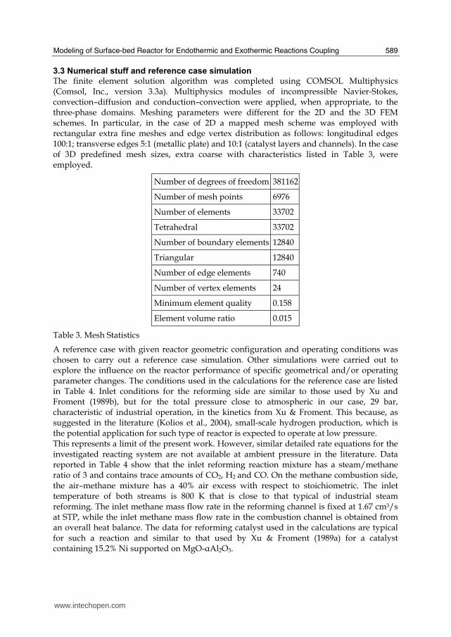
Modeling of Surface-bed Reactor for Endothermic and Exothermic Reactions Coupling
589
33 Numerical stuff and reference case simulation
The finite element solution algorithm was completed using COMSOL Multiphysics (Comsol Inc version 33a) Multiphysics modules of incompressible Navier-Stokes convectionndashdiffusion and conductionndashconvection were applied when appropriate to the three-phase domains Meshing parameters were different for the 2D and the 3D FEM schemes In particular in the case of 2D a mapped mesh scheme was employed with rectangular extra fine meshes and edge vertex distribution as follows longitudinal edges 1001 transverse edges 51 (metallic plate) and 101 (catalyst layers and channels) In the case of 3D predefined mesh sizes extra coarse with characteristics listed in Table 3 were employed
Number of degrees of freedom 381162
Number of mesh points 6976
Number of elements 33702
Tetrahedral 33702
Number of boundary elements 12840
Triangular 12840
Number of edge elements 740
Number of vertex elements 24
Minimum element quality 0158
Element volume ratio 0015
Table 3 Mesh Statistics
A reference case with given reactor geometric configuration and operating conditions was chosen to carry out a reference case simulation Other simulations were carried out to explore the influence on the reactor performance of specific geometrical andor operating parameter changes The conditions used in the calculations for the reference case are listed in Table 4 Inlet conditions for the reforming side are similar to those used by Xu and Froment (1989b) but for the total pressure close to atmospheric in our case 29 bar characteristic of industrial operation in the kinetics from Xu amp Froment This because as suggested in the literature (Kolios et al 2004) small-scale hydrogen production which is the potential application for such type of reactor is expected to operate at low pressure This represents a limit of the present work However similar detailed rate equations for the investigated reacting system are not available at ambient pressure in the literature Data reported in Table 4 show that the inlet reforming reaction mixture has a steammethane ratio of 3 and contains trace amounts of CO2 H2 and CO On the methane combustion side the airndashmethane mixture has a 40 air excess with respect to stoichiometric The inlet temperature of both streams is 800 K that is close to that typical of industrial steam reforming The inlet methane mass flow rate in the reforming channel is fixed at 167 cm3s at STP while the inlet methane mass flow rate in the combustion channel is obtained from an overall heat balance The data for reforming catalyst used in the calculations are typical for such a reaction and similar to that used by Xu amp Froment (1989a) for a catalyst containing 152 Ni supported on MgO-αAl2O3
wwwintechopencom
Recent Advances in Modelling and Simulation
590
Table 4 Data used for reference case calculations
Figure 2 Temperature space profiles along the reactor centerline of the reforming channel (solid blue) centerline of the combustion channel (solid red) centerline of the reforming catalyst (dashed blue) and centerline of the combustion catalyst (dashed red)
Gas phase Reforming channel Combustion channels Inlet conditions co-current flow compositions vol H2O 6666 CH4 3333 750 CO2 1 10-3 CO 1 10-3 O2 1943 N2 7307 H2 1 10-3 temperature 800 K 800 K CH4 mass flow rate cm3s (STP) 167 0417 pressure 101 kPa (channel outlet) 101 kPa (channel outlet) channel width m 2 10-3 1 10-3 channel height m 10 10-2 average velocity ms 097 087 channel length m 5 10-2 Catalyst layers thickness (c) μm 200 Average pore radius nm 15 porosity 05 tortuosity 4 Metal plates Thickness m 5 10-4 material aluchrom Thermal conductivity w(m K) Temperature dependent
wwwintechopencom
Modeling of Surface-bed Reactor for Endothermic and Exothermic Reactions Coupling
591
Figure 3 Axial profiles of heat flux in the y direction adjacent to the reforming catalyst in the metallic plate (solid line) in the reforming channel (dotted line)
The catalyst layer density is assumed to be 2300 kgm3 For both type of catalyst layers an average pore radius of 15 nm together with a porosity of 05 and a tortuosity factor of 4 are considered These values are typical for both combustion and reforming catalysts (De Deken et al 1982 Xu amp Froment 1989 b Groppi et al 1995)
4 Results
41 Thermal behaviour
Given the symmetry of the reactor for both 3D and 2D simulations only half of the reactor was simulated by substituting the proper boundary conditions (symmetry) in place of the lacking half Results in simulations performed with the 2D model under the reference case conditions are shown in Figures 2-7 The first aspect to consider is the thermal coupling of steam reforming with catalytic combustion in terms of evolution of both exothermic and endothermic conversion Figure 2 shows the temperature longitudinal profiles on the centerlines of the combustion and the reforming channels and in the combustion and reforming catalysts The profiles are very close each other and they increase from the inlet value of 800 to 914 K at the reactor outlet Therefore the catalytic combustion provides the necessary heat flux to heat up both reaction mixtures and to simultaneously drive the endothermic process A methane conversion at the reactor outlet of 089 for combustion and 074 for reforming are achieved Figure 3 shows the axial profiles of the absolute values of the heat fluxes in the y direction at the boundaries of the reforming catalyst One profile (solid line) is the heat flux from the metallic plate towards the reforming catalyst the other the heat flux from the reforming catalyst to the gas mixture in the reforming channel The two profiles present similar shapes with a maximum at 7 mm and 5 mm from the reactor entrance (distances within which the profiles are increasing) The difference between the profiles represents the heat absorbed by the reforming reaction system (eqs (1) and (2)) The maxima heat fluxes generated and consumed reach values of the order of 105 Wm2 ie 10 Wcm2 that considering the very small temperature gradients (Figure 2) is a very high value with respect to that attainable in industrial practice
wwwintechopencom
Recent Advances in Modelling and Simulation
592
a)
b)
Figure 4 Reactor temperature transverse profiles a at 15 cm from the reactor entrance b at 10 cm from the reactor outlet From 0 to 1 reforming channel From 1 to 12 reforming catalyst From 12 to 17 metallic plate From 17 to 19 combustion catalyst From 19 to 24 combustion channel
A further aspect to be examined is the magnitude of the transverse temperature gradients From Figure 2 it is already evident that the four profiles are very close each other However the transverse temperature gradients can be better analyzed from Figure 4 where the transverse temperature profiles at 15 cm (Figure 4a) from the reactor entrance and at 05 cm (Figure 4b) from the reactor outlet are shown In particular Figure 4a which pertains to the distance from the reactor inlet where the highest transverse temperature gradients develop evidences that the maximum temperature difference between reforming and combustion catalyst is 07 K while the maximum difference between the reforming and combustion channels is less than 10 K although that inside the reforming channel is almost 20 K Much lower differences can be observed close to the reactor outlet Specifically Figure 4b shows that the maximum temperature difference between reforming and combustion catalyst is 01 K that between the reforming and combustion channels is less than 1 K and that inside the reforming channel is almost 2 K As a result the high thermal conductivity of the metallic
wwwintechopencom
Modeling of Surface-bed Reactor for Endothermic and Exothermic Reactions Coupling
593
wall makes possible an efficient heat transfer at a temperature difference of the order of tenths of K With reference to Figure 4 it must be remarked that the value 0 of the transverse coordinate represents the centre of the reactor and the centre of the reforming channel Therefore at that point there is not a physical boundary the heat flux and the momentum flux are both zero and the x component of the gas velocity is maximum On the contrary the value 29 10-3 m of the transverse coordinate represents a solid wall that is the external boundary of the reactor and the boundary of the combustion channel This means that the heat flux is zero both components of the gas velocity are zero and the momentum flux is not zero This is one of the reasons because for the same distance in the transverse direction (y) the gas phase temperature difference in the reforming channel results always larger than that in the combustion channel (Figures 2 4a and 4b)
42 Mass transfer and chemical reactions
The concentration on the centerline of the reforming channel of the various species involved in the reactions occurring within the reforming catalyst are shown in Figure 5 This yields an overall picture of the reactor performance The hydrogen concentration steadily increases from the initial value to about 9 molm3 resulting the most abundant component in the exit gas mixture The ratio between the hydrogen concentration and CO concentration is very high (about 9)
Figure 5 Axial profiles of species concentrations on the centerline of the reforming channel
One important aspect to determine is the effect of interphase mass transport resistance Figure 6a shows the methane concentration axial profiles on the centerlines of the combustion channels and of the combustion catalyst while Figure 6b shows the correspondent profiles for the reforming section of the reactor From these Figures the differences between the channel and the catalyst profiles in each section yield a measure of the resistance to the interphase transport As expected in the combustion section the axial methane concentration profiles both in the channel and in the catalyst show an exponentially decreasing trend which reflects the relatively simple kinetics of the reaction In contrast a more complex trend is shown by the axial methane concentration profile in the catalyst because of the non linearity of the kinetics and the simultaneous occurrence of two
wwwintechopencom
Recent Advances in Modelling and Simulation
594
reactions (eqs (1) and (2)) Another aspect to examine is the size of the concentration gradients in the transverse direction These can be appreciated from Figure 7 where the transverse methane concentration profiles at 15 cm from the reactor inlet and at 05 cm from the reactor outlet are shown In particular the first profile which pertains to the distance from the reactor inlet where the highest transverse temperature gradients develops evidences that the gradients inside the reforming and the combustion channels are negligible with respect to the gradients in the catalyst phase The order of magnitude of these latter range from 105 molm4 close to the reactor inlet to 104 molm4 in the remaining part of the reforming catalyst and in all the combustion catalyst too
a)
b)
Figure 6 Axial methane concentration profiles along the reactor (a) solid line combustion channel dashed line combustion catalyst (b) solid line reforming channel dashed line reforming catalyst
wwwintechopencom
Modeling of Surface-bed Reactor for Endothermic and Exothermic Reactions Coupling
595
Figure 7 Methane concentration transverse profiles at 15 cm from the reactor entrance (solid line) and at 10 cm from the reactor outlet (dashed line) From 0 to 1 reforming channel From 1 to 12 reforming catalyst From 12 to 17 metallic plate From 17 to 19 combustion catalyst From 19 to 24 combustion channel
43 Methane concentration in the combustion channel
A basic requirement of the system in the object which is thought to be used for energy feeding of portable electric devices should be the complete reliability with respect to possible uncontrolled rises in temperature or even to a possible explosion hazard In this view the coordination between exothermic and endothermic reaction rates appears fundamental However even in the case such a coordination occurs the possible progress of the combustion reaction in the homogeneous phase may represent an hazard In addition if the concentration of the reacting mixture entering the combustion channel is within the flammability limits and the temperature becomes high enough it could ignite before the reactor inlet Therefore for safety purposes the occurrence of the exothermic reaction here represented by the methane combustion in the homogeneous phase should be avoided A possible way to make the system of hydrogen generation intrinsically safe is to feed the combustion mixture at a methane concentration below the LEL (lower explosivity limit) Considering that at STP the LEL of methane in air is about 5 vol that the autoignition temperature for airmethane mixtures is around 900 K the extimated LEL of methane in air at such a temperature should be about 3 vol (Crowl amp Louvar (2002)) Therefore a safe operating concentration should be about 3 vol To this purpose in this work beside those carried out under the conditions considered in the reference case other simulations were effected for which for a given methane mass flow rate its concentration at the combustion channel inlet was kept below 3 vol In this way the system is intrinsically safe because the reacting mixture cannot ignite spontaneously In addition the simulation becomes more realistic the contribution to the methane combustion of the homogeneous phase being really absent as implicitly hypothesized in this work
wwwintechopencom
Recent Advances in Modelling and Simulation
596
Figure 8 Temperature distribution over the boundaries of the 3D reactor
The comparison of results of runs performed under these conditions with those effected under the conditions of the reference case are reported in the following when analyzing the influence of various parameters on the reactor performance These simulations are labeled in the paper as n-expl in contrast to the others that are recalled as expl
44 Comparison between 2D and 3D results
For given operating conditions some simulations were carried out in both 2D and 3D geometry In principle a plane 2D geometry represents a slice of the reactor where the z dimension is greatly prevalent with respect to the y dimension Actually the model reactor has not such characteristics the length in the z dimension being 10 mm that is only 5 times the reforming channel width This means that the boundary effects due to the presence of the boundary walls in the z direction may have a significant influence on the velocity temperature and species concentration profiles that certainly influence the overall reactor performance Figures 8 shows the temperature distribution over the boundaries of the 3D reactor obtained under operating conditions of the reference case From this Figure the effect of the boundaries along the z direction appears evident
wwwintechopencom
Modeling of Surface-bed Reactor for Endothermic and Exothermic Reactions Coupling
597
Figure 9 Temperature space profiles along the reactor calculated with the 2D model (for the legend see caption to Figure 2)
Figure 10 Temperature space profiles along the reactor calculated with the 3D model (for the legend see caption to Figure 2)
Figures 9 and 10 show the reactor temperature longitudinal profiles on the centerlines of the combustion and the reforming channels and on the centerline of the combustion and reforming catalysts in the case of 2D and 3D geometry models respectively Both were calculated under the same operating conditions ie same inlet mass flow rates and compositions of the reference case (expl) but inlet temperature of 900 K In the case of the
wwwintechopencom
Recent Advances in Modelling and Simulation
598
3D simulation (Figure 10) the temperature profiles are those lying over a xy plane intersecting the reactor in the middle of its height along z The two sets of profiles appear quite similar the temperatures in the combustion section (catalyst and channel) are always slightly higher than the corresponding ones in the reforming section However a closer inspection reveals some significant differences In the 2D case the temperature after an initial slow growth increases steadily from 900 K at the reactor inlet up to 965 K at the reactor outlet while in the other case it grows faster reaches 960 K at 60 of the reactor length and remains constant up to the outlet Another difference is represented by the larger transverse temperature gradients of the 3D case with respect to 2D In the 2D case they are comparable with those observed in Figure 2 for the reference case while in the 3D case they are almost double This is true for all combinations ie catalyst-catalyst catalyst-channel and channel-channel On the whole the 3D case shows a faster progress of the reactions with consequent need for faster heat transfer These differences in the thermal behaviour between 2D and 3D simulations persist when the comparison is extended to other operating conditions and in addition they reflect the better overall performance of the 3D reactor with respect to the 2D as can be seen by the following discussion The quantitative comparison between the 2D and 3D simulations was made with respect to the main results ie the methane conversion in both the combustion and the steam reforming channels as obtained from equation 5 Further beside the methane conversions other parameters are employed ie a) the gas hourly space velocities GHSV in the combustion and steam reforming sides of the reactor calculated as ratio between gas flow rates at the reactor inlet temperature and volume of catalyst b) the maximum temperature reached in the reactor c) the mean gas residence time trm in both the combustion and the reforming channel calculated as ratio between the gas flow rates at the reactor inlet temperature and the volume of the channel and d) the hydrogen yield φH2 evaluated as ratio between the amounts of methane reacted and hydrogen produced GHSV and trm were useful to allow the comparison of simulations carried out by changing the catalyst volume or the channel width as discussed later Results of simulations carried out with the 2D and 3D models under various operating conditions are reported in Table 5 Those referring to the operating conditions of the reference case are listed in the first two rows of such a Table The other operating conditions are i) same inlet temperature of the reference case but different methane concentration in the combustion channel (3rd and 4th rows of Table 5) and ii) different inlet temperatures for the two conditions above (5th-8th rows of Table 5) Focusing the comparison on the results of the simulations in 2D and 3D with the same operating conditions it appears that in general the methane conversions at the reactor outlet calculated with the 2D geometry in both the combustion and reforming channels are lower than the correspondent in 3D geometry but in one case (Xch4-sr 3rd and 4th rows of the Table) This finding reflects the differences in the thermal behaviour discussed above In any case such conversions differ by less than 10 but in the last two rows of the Table where the differences are larger It is worth noting however that even in this case the values of the conversions are congruent with the overall results of the simulation For instance the lower value of Xch4-co in the 2D with respect to the correspondent in 3D results in a lower value of Xch4-sr and in a lower maximum temperature reached in the reactor
wwwintechopencom
Modeling of Surface-bed Reactor for Endothermic and Exothermic Reactions Coupling
599
Geometry Tin K
Xch4-co Xch4-sr Tmax K Trm-co ms
Trm-sr ms
GHSVco h-1
GHSVsr h-1
φH2
2D expl 800 089 074 914 0057 0026 314840 702884 329
3D expl 800 096 077 914 0057 0026 314840 702884 333
2D n-expl 800 036 045 827 0020 0026 900588 702884 344
3D n-expl 800 040 041 828 0020 0026 900588 702884 356
2D expl 900 095 090 965 0051 0023 354194 790745 305
3D expl 900 099 093 960 0051 0023 354194 790745 300
2D n-expl 900 049 069 900 0018 0023 1013162 790745 322
3D n-expl 900 068 079 920 0018 0023 1013162 790745 318
Table 5 Comparison of 2D and 3D results obtained under the same operating conditions
For what concerns the hydrogen yield focusing again the comparison on the results of the simulations in 2D and 3D at the same operating conditions data show that φH2rsquos obtained with the 2D geometry model are lower than that in 3D model but in one case (7th and 8th row of Table 5) It is worth noting that φH2=3 would be the stoichiometric value if reaction (1) were the only occurring in the reforming catalyst so that the amount exceeding 3 is due to the contribution of reaction (2) Data in Table 5 also shows the influence on the reactor performance of temperature and inlet methane concentration in the combustion channel In the case of inlet temperature of 900 K and methane concentration within the explosivity limits (case referring to results in Figures 9 and 10) the methane conversion is practically 1 (3D model) for the combustion reaction and very high for the reforming reactions However under these conditions the hydrogen yield is the lowest In contrast when the highest hydrogen yield is reached the lowest methane conversion is achieved Similar considerations can be done for the other results in the Table so that a general trend can be drawn from such results The higher the maximum temperature reached in the reactor the higher the methane conversions and the lower the hydrogen yield
45 Influence of the channels width
The reactor thermal behaviour and performance was studied for different channels width Wc at constant inlet flow rates of the reaction mixtures Runs were also carried out by keeping constant the mean inlet velocities of reaction mixtures The variation range for the combustion channels width Wc-co was 1-15 mm and for the reforming channel width Wc-sr 2-3 mm All other parameters were kept at their reference case values Keeping constant the inlet mass flow rates and altering the channel width results in modifying the inlet velocities in the reactor and consequently the mean residence time (trm) of the gases in the channels but the GHSVrsquos do not change The results in terms of methane conversions in the combustion and reforming channels are reported in Table 6 for the reference cases (3rd and 4th row in Table) and for cases where the methane concentration in the combustion channels were below the LEL (1st and 2nd row) At constant mass flow rates the influence of the channel width or better of trm appears negligible under n-expl conditions with a slight
wwwintechopencom
Recent Advances in Modelling and Simulation
600
prevalence of the reactor with narrower channels and weak under expl conditions with in contrast better performance for the reactor with wider channels Therefore it is not possible to draw conclusions
Wc-sr mm
Tin K
Xch4 -
co Xch4-sr
Tmax K
trm-co ms
trm-sr ms
GHSVco h-1
GHSVsr h-1
2 n-expl 800 036 045 827 0020 0026 900588 702884
3 n-expl 800 034 044 819 0030 0038 900588 702884
2 expl 800 089 074 914 0057 0026 314840 702884
3 expl 800 092 081 940 0086 0038 314840 702884
Vcost- 3 n-expl 800 022 033 800 0020 0026 1350882 1054327
Table 6 Comparison between reactor performance as a function of channel width
Unlike the previous case where inlet flow rates were kept constant an increase in channel width keeping the mean gas velocity and the value of trm constants affects significantly the outlet conversions In this case the amount of reactants flowing through the reactor per unit catalyst volume and then GHSV increases (compare 1st and 5th rows in Table 5) Increasing channel widths from their reference case value (Wc-sr = 2 mm and Wc-co= 1) at constant gas inlet velocity leads to methane conversion reduction because a) the catalyst amount becomes insufficient for the amount of reactants fed in the reactor and b) the external mass transfer resistances play a stronger role The overall reaction heat fluxes remain the same as channel width increases leaving a similar amount of sensible heat to be used for heating up larger amounts of reactants This results in lower temperatures along the reactor
46 Influence of catalyst thickness
The influence of catalyst thickness c on the reactor behaviour was studied by keeping constant the reactants mass flow rates The reactor operation was simulated for three values of catalyst thickness ie 200 100 and 50 microm while keeping all the other parameters at their reference case values but for what concerns the inlet methane concentration in the combustion channel that was at non explosive level This with respect to the reference case corresponds to decreasing GHSV of factors 2 and 4 respectively Changes in the catalyst thickness influence considerably both thermal behaviour and outlet conversions As above the comparison is made through the methane conversions achieved in the two cases both in the steam reforming and in the combustion channels The results are reported in Table 7 It is evident that the loss of performance due to a decrease of 50 of c from 200 to 100 μm is almost negligible This is mainly due to the conservative parameters used for defining the catalyst layer characteristics (ie mean pore radius and tortuosity) that results in a very impervious path for diffusing gases However when c is further decreased methane conversion both in the combustion and in the reforming section significantly decrease The hydrogen yield does not change too much within the limits of the three cases analyzed
wwwintechopencom
Modeling of Surface-bed Reactor for Endothermic and Exothermic Reactions Coupling
601
δc μm
Tin K Xch4 -co Xch4-sr Tmax Ktrm-co ms
trm-sr ms
GHSVco h-1
GHSVsr h-1
φH2
200 n-expl 800 036 045 827 0020 0026 900588 702884 344
100 n-expl 800 035 045 827 0020 0026 1801176 1405768 344
50 n-expl 800 027 038 800 0020 0026 3602352 2811536 342
Table 7 Comparison between reactor performance as a function of catalyst thickness
5 Discussion
As seen in the previous section (4) there are several operating parameters that influence the performances of the system They are typical of reacting systems and can be summarized as GHSVrsquos tmrrsquos and inlet gas temperatures The particularity of the present case is the simultaneous occurrence of two coupled reactions one exothermic and the other endothermic in which the extent of the second depends on the extent (heat produced) of the first and the effectiveness of the heat transferred In addition the coupling of the two reactions does not exclude to have for each set of values of the mentioned parameters pertaining to one reaction several sets of parameters for the other reaction This makes the system quite complex and difficult to analyze However some general considerations can be drawn
Figure 11 Methane conversions in the combustion and reforming sides of the reactor as a function of GHSV for various operating conditions available in Table 6 and 7
The first is that as expected GHVS plays a key role in determining the reactor performances although this is supported by only a part of the data For instance data in Table 7 pertaining to simulations of the influence of such a parameter carried out by changing GHSV in the same way for both sections of the reacting system shows a clear effect of GHSV the reactor
0 1000000 2000000 3000000 4000000
GHSV h-1
02
04
06
08
1
XC
H4
-co a
nd
XC
H4
-sr -
data from Table 7 comb side
data from Table 7 refor side
data from Table 6 comb side
data from Table 6 refor side
wwwintechopencom
Recent Advances in Modelling and Simulation
602
performance decreases as GHSV increases on both sides of the reactor Such an influence does not appear strong the conversion change being about 20 against GHSV variations of a factor 4 (Figure 11) The influence of GHSV is more evident from data in Table 6 pertaining to simulations of the influence of tmr In fact also in this case a clear trend appears and the influence even though in the same direction of the previous case appears much stronger since with respect to a GHSV change of about 20 the methane conversion varies by a factor 4 (Figure 11) Such a strong influence is due to the combined effect of tmr especially on the combustion side of the reactor (cfr Table 6) Instead for data in Table 5 pertaining to simulations of the reliability of 2D and 3D models and the effect of gas inlet temperature it is not possible to highlight a clear influence The comparison between the results obtained with the 2D and 3D models under the same operating conditions have evidenced differences in the performance of the reactor not large but significant When we move from 2D to 3D models such differences result in an increase from 5 to 20 of both Xch4-co and Xch4-sr which reflects a different thermal behavior of the reacting system and influence also the hydrogen yield It is worth noting that the computation time required in the two cases is very different Specifically using an HP xw8400workstation equipped with 2 Xeon processors and 4 GB of RAM a 2D simulation takes on the average about 20 minutes with respect to 50-60 hours necessary in the 3D case It is impossible by now to establish which is the more correct or the more reliable In particular it should be assessed if 2D simulations are suitable for purpose of reactor design and experimental data interpretation The answer should come from the comparison of the results of such simulations with experimental data obtained with a real reactor geometrically comparable operated under conditions as much as similar to those fixed for the simulations This represents argument for coming work of the authors Further interesting aspects to be studied are the simulation of unsteady-state conditions and specifically of the system start-up and of the system response to small changes in the gas feeding flow rates and temperatures
6 Conclusions
Methane steam reforming coupled with methane catalytic combustion by means of indirect heat transfer in a surface-bed catalytic reactor was studied by 2D and 3D models The reactor consists of a central reforming channel and two lateral combustion channels A reference case for what concerns operating conditions and reactor geometry was chosen and its simulation was carried out Changes of reactor performance as consequence of operating parameters and reactor geometry variations were analyzed with respect to the reference case The simulation showed that suitable amount of fuel and adequate catalyst activity in the combustion channel can provide enough heat to simultaneously heat up the reaction mixture and drive the endothermic process The proximity between the heat source and the heat sink increases the efficiency of heat transfer resulting in transverse temperature gradients do not exceeding generally 07 K across the metallic wall and 20 K across the gas in the channel Decrease of transverse temperature differences and intraphase mass transfer resistances have the global effect of reducing the reactor dimension and the catalyst amount The influence of channels width and catalyst layer thickness on reactor behaviour was also studied At constant inlet flow rates changes of channel width in the range 1ndash2 mm do not introduce significant differences in the reactor performance Rather small differences in the
wwwintechopencom
Modeling of Surface-bed Reactor for Endothermic and Exothermic Reactions Coupling
603
catalyst axial temperature profiles and outlet methane conversions are observed In contrast altering the channel width at constant inlet velocities has strong influence Larger channel width results in lower conversion and smoother axial temperature profiles Intraphase resistances are present even for catalyst thickness of micrometers for both reforming and combustion processes Increasing GHSV that is the inlet flow ratecatalyst volume ratio leads to lower outlet conversions Due to different effect of catalyst layer thickness on reforming and combustion channels there are significant changes in the reactor temperature profile Results indicate that steam reforming of methane in a surface-bed reactor is feasible provided that mass flow rates channels width catalyst loadings and thickness are properly designed
7 Notation
cp specific heat J(mol K) c concentration molm3 Deff effective diffusion coefficient m2s D molecular diffusion coefficient m2s GHSV gas hourly space velocity h-1 k thermal conductivity W(m K) or reaction rate constant Ke equilibrium constant M molecular weight kgmol LEL lower explosivity limit vol
unit vector perpendicular to the flux surface
N molar flux at the boundary mol(m2 s) p partial pressure bar P total pressure bar q thermal flux at the boundary J(m2 s) r reaction rate various dimensions (see eqs 1rsquo 2rsquo and 3rsquo) Rp catalyst pore radius nm STP standard temperature and pressure (298 K and 101 103 Pa) t time s T temperature K ts transverse surface ux Velocity component on the x coordinate
velocity vector
v normal component of velocity at the channel ingress x axial coordinate m X conversion y transverse coordinate m Wc distance between the reactor plates m z vertical coordinate m Greek letters ΔH0r heat of reaction at reference state conditions KJmol c catalyst thickness μm catalyst porosity φ atomic diffusion volume or chemical reaction yield
wwwintechopencom
Recent Advances in Modelling and Simulation
604
θ stoichiometric coefficient ρ density kgm3 τ catalyst tortuosity
Subscripts and superscripts cat catalyst co combustion CH4 methane H2 hydrogen in inlet i chemical species j channel k reaction l phase rm mean residence s metal sheet sr steam reforming 0 channel ingress 1 reforming reaction 2 water gas shift reaction 3 combustion reaction
8 Acknowledgements
The authors gratefully acknowledge the financial support of MIUR under grant PRIN ndeg 2006094333004
9 References
Akers WW amp Camp DP (1955) Kinetics of the methanendashsteam reaction AIChE Journal Vol 1 471ndash475 ISSN0001-1541
Allen DW Gerhard ER amp Likins Jr MR (1975) Kinetics of the MethanendashSteam Reaction Ind Eng Chem Proc Des Dev Vol 14 No 3 256-259 ISSN0196-4305
Aparicio L (1997) Transient Isotopic Studies and Microkinetic Modeling of Methane Reforming over Nickel Catalysts Journal of Catal Vol 165 No 2 262-274 ISSN 0021-9517
Avci AK Trimm DL amp İlsen Oumlnsan Z (2001) Heterogeneous reactor modeling for simulation of catalytic oxidation and steam reforming of methane Chem Eng Sci Vol 56 No 2 641-649 ISSN0009-2509
Bridger GW (1980) The steam reforming of hydrocarbons Catalysis Vol 3 39-69 ISSN0140-0568
Cao C Wang Y amp Rozmiarek RT (2005) Heterogeneous reactor model for steam reforming of methane in a microchannel reactor with microstructured catalysts Catal Today Vol 110 No 1-2 92ndash97 ISSN 0920-5861
Craciun R Shereck B amp Gorte RJ (1998) Kinetic studies of methane steam reforming on ceria-supported Pd Catal Lett Vol 51 No 3ndash4 149-153 ISSN 1011-372x
wwwintechopencom
Modeling of Surface-bed Reactor for Endothermic and Exothermic Reactions Coupling
605
Crowl DA amp Louvar JF (2002) Chemical Process Safety fundamentals with applications 2nd ed Prentice Hall PTR Upper Saddle River NJ USA ISBN 0-13mdash018176-5
De Deken J C Devos E F amp Froment G F (1982) Steam reforming of natural gas Intrinsic kinetics diffusional influences and reactor design ACS Symposium Series 196 181ndash197 ISSN0097-6156
Ehrfeld W amp Hessel V Lowe H (2000) Microreactor Wiley-VCH Verlag GmbH D-69469 ISBN Weinheim Germany
Gosiewski K (2001) Simulations of non-stationary reactors for catalytic conversion of methane to synthesis gas Chem Eng Sci Vol 56 No 4 1501-1510 ISSN
Groppi G Belloli A Tronconi E Forzatti P (1995) A comparison of lumped and distributed models of monolith catalytic combustors Chem Eng Sci Vol 50 No 17 2705ndash2715 ISSN0009-2509
Holladay JD Wang Y amp Jones E (2004) Review of Developments in Portable Hydrogen Production Using Microreactor Technology Chem Rev Vol 104 No 10 4767-4790 ISSN 0009-2665
Hou K amp Hughes R (2001) The kinetics of methane steam reforming over a Ni-Al2O3 catalyst Chem Eng Journal Vol 82 No 1-3 311-328 ISSN 1385-8947
Jamal Y amp Wyszynski M L (1994) On-board generation of hydrogen-rich gaseous fuels a review Int J of Hydrogen Energy Vol 19 No 7 557-572 ISSN 0360-3199
Jensen KF (2001) Microreaction engineering is small better Chem Eng Sci Vol 56 No 2 293-303 ISSN0009-2509
Kolios G Gritsch A Glo1ckler B amp Sorescu G (2004) Novel Reactor Concepts for Thermally Efficient Methane Steam Reforming Modeling and Simulation Ind Eng Chem Res Vol 43 No 16 4796-4808 ISSN0888-5885
Kruger P Blakeley J amp Leaver J (2003) Potential in New Zealand for use of hydrogen as a transportation fuel Int J of Hydrogen Energy Vol 28 No 8 795ndash802 ISSN 0360-3199
Kvamsdal HM Svendsen HF Hertzberg T amp Olsvik O (1999) Dynamic simulation and optimization of a catalytic steam reformer Chem Eng Sci Vol 54 No 13-14 2697-2706 ISSN0009-2509
Lerer M Duic N Alves LM amp Carvalho MG (2006) H2 RES energy planning tool for increasing the penetration of renewable energy sources in island energy supply In New and Renewable Technologies for Sustanaible Development MG Carvalho and NH Afgan (Ed s) 15-30 World Scientific ISBN 10 981-270-505-8 Singapore
Lerou JJ amp Ng KM (1996) Chemical reaction engineering A multiscale approach to a multiobjective task Chem Eng Sci Vol 51 No 10 1595-1614 ISSN0009-2509
Lincoln SF (2006) Challenged Earth ch7 Imperial College Press ISBN 1-86094-526-0 London
Loffler D G Faz C F Sokolovskii V amp Iglesia E (2002) Catalytic separator plate reactor and method of catalytic reforming of fuel to Hydrogen PCT Int Appl WO 0228769 A2
Luna C amp Becerra AM (1997) Kinetics of methane steam reforming on a Ni on alumina-titania catalyst React Kinet Catal Lett Vol 61 No 2 369-374 ISSN 0133-1736
Marschner F Renner HJ amp Boll W (2005) Electronic Encyclopedia Release 2005 7th ed in Ullmannrsquos Encyclopedia of Industrial Chemistry M Bohnet et al (Eds) Vol a12 John Wiley amp Sons ISBN-13 978-3-527-30385-4
wwwintechopencom
Recent Advances in Modelling and Simulation
606
Moore R B amp Raman V (1998) Hydrogen infrastructure for fuel cell transportation Int J of Hydrogen Energy Vol 23 No 7 617-620 ISSN 0360-3199
Perry RH amp Green DW (1999) Perrys Chemical Engineers Handbook (7th Ed) McGraw-Hill ISBN 0-07-049841-5
Robbins F A Zhu H amp Jackson GS (2003) Transient modeling of combined catalytic combustionCH4 steam reformng Catal Today Vol 83 No 1-4 141ndash156 ISSN 0920-5861
Rostrup-Nielsen JR Christiansen LJ amp BakHansen JH (1988) Activity of steam reforming catalysts Role and assessment Appl Catal Vol 43 No 2 287-303 ISSN0166-9834
Rostrup-Nielsen JR (1995) Innovation and the catalytic process industry - the science and challenge Chem Eng Sci Vol 50 No 24 4061-4071 ISSN0009-2509
Rostrup-Nielsen JR Dybkjaer I amp Coulthard GRG (2001) Topical Conf Proc AIChE Spring National Meeting Houston TX April Paper No 1
Rostrup-Nielsen JR (2004) Fuels and Energy for the Future The Role of Catalysis Catal Rev - Science and Engineering Vol 46 No 3ndash4 247-270 ISSN0161-4940
Schubert K Brandner J Fichtner M Linder G Schyhulla U amp Wenka A (2001) Microstructure devices for applications in thermal and chemical process engineering Microscale Thermophys Eng Vol 5 No 1 17-39 ISSN1089-3954
Tronconi E amp Groppi G (2000) A study on the thermal behavior of structured plate-type catalysts with metallic supports for gassolid exothermic reactions Chem Eng Sci Vol 55 Issue 24 December 6021-6036 ISSN0009-2509
Wang Y Johnson BR Cao C Chin Y Rozmiarek RT Gao Y Tonkovich AL (2005) Engineered catalysts for microchannel reactor applications In Microreactor Technology and Process Intensification Y Wang J Holladay (Eds) 65-73 ACS Symposium Series Vol 914 ISBN-13 9780841239234
Xu J amp Froment GF (1989a) Methane steam reforming II Diffusional limitations and reactor simulation AIChE Journal Vol 35 No 1 97-103 ISSN0001-1541
Xu J amp Froment GF (1989b) Methane steam reforming methanation and water-gas shift I Intrinsic kinetics AIChE Journal Vol 35 No 1 88-96 ISSN0001-1541
Zanfir M amp Gavriilidis A (2003) Catalytic Combustion Assisted Methane Steam Reforming Chem Eng Sci Vol 58 No 17 3947ndash 3960 ISSN0009-2509
wwwintechopencom
Modelling and SimulationEdited by Giuseppe Petrone and Giuliano Cammarata
ISBN 978-3-902613-25-7Hard cover 688 pagesPublisher I-Tech Education and PublishingPublished online 01 June 2008Published in print edition June 2008
InTech EuropeUniversity Campus STeP Ri Slavka Krautzeka 83A 51000 Rijeka Croatia Phone +385 (51) 770 447 Fax +385 (51) 686 166wwwintechopencom
InTech ChinaUnit 405 Office Block Hotel Equatorial Shanghai No65 Yan An Road (West) Shanghai 200040 China
Phone +86-21-62489820 Fax +86-21-62489821
This book collects original and innovative research studies concerning modeling and simulation of physicalsystems in a very wide range of applications encompassing micro-electro-mechanical systems measurementinstrumentations catalytic reactors biomechanical applications biological and chemical sensorsmagnetosensitive materials silicon photonic devices electronic devices optical fibers electro-microfluidicsystems composite materials fuel cells indoor air-conditioning systems active magnetic levitation systemsand more Some of the most recent numerical techniques as well as some of the software among the mostaccurate and sophisticated in treating complex systems are applied in order to exhaustively contribute inknowledge advances
How to referenceIn order to correctly reference this scholarly work feel free to copy and paste the following
Salvatore Vaccaro and Paolo Ciambelli (2008) Modeling of Surface-bed Reactor for Endothermic andExothermic Reactions Coupling Modelling and Simulation Giuseppe Petrone and Giuliano Cammarata (Ed)ISBN 978-3-902613-25-7 InTech Available fromhttpwwwintechopencombooksmodelling_and_simulationmodeling_of_surface-bed_reactor_for_endothermic_and_exothermic_reactions_coupling
copy 2008 The Author(s) Licensee IntechOpen This chapter is distributedunder the terms of the Creative Commons Attribution-NonCommercial-ShareAlike-30 License which permits use distribution and reproduction fornon-commercial purposes provided the original is properly cited andderivative works building on this content are distributed under the samelicense
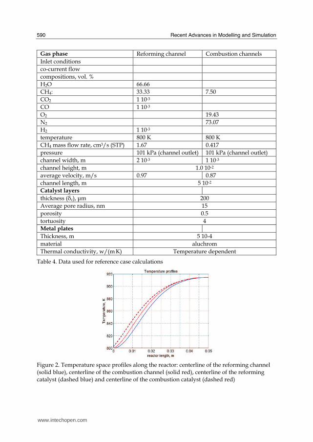
Recent Advances in Modelling and Simulation
590
Table 4 Data used for reference case calculations
Figure 2 Temperature space profiles along the reactor centerline of the reforming channel (solid blue) centerline of the combustion channel (solid red) centerline of the reforming catalyst (dashed blue) and centerline of the combustion catalyst (dashed red)
Gas phase Reforming channel Combustion channels Inlet conditions co-current flow compositions vol H2O 6666 CH4 3333 750 CO2 1 10-3 CO 1 10-3 O2 1943 N2 7307 H2 1 10-3 temperature 800 K 800 K CH4 mass flow rate cm3s (STP) 167 0417 pressure 101 kPa (channel outlet) 101 kPa (channel outlet) channel width m 2 10-3 1 10-3 channel height m 10 10-2 average velocity ms 097 087 channel length m 5 10-2 Catalyst layers thickness (c) μm 200 Average pore radius nm 15 porosity 05 tortuosity 4 Metal plates Thickness m 5 10-4 material aluchrom Thermal conductivity w(m K) Temperature dependent
wwwintechopencom
Modeling of Surface-bed Reactor for Endothermic and Exothermic Reactions Coupling
591
Figure 3 Axial profiles of heat flux in the y direction adjacent to the reforming catalyst in the metallic plate (solid line) in the reforming channel (dotted line)
The catalyst layer density is assumed to be 2300 kgm3 For both type of catalyst layers an average pore radius of 15 nm together with a porosity of 05 and a tortuosity factor of 4 are considered These values are typical for both combustion and reforming catalysts (De Deken et al 1982 Xu amp Froment 1989 b Groppi et al 1995)
4 Results
41 Thermal behaviour
Given the symmetry of the reactor for both 3D and 2D simulations only half of the reactor was simulated by substituting the proper boundary conditions (symmetry) in place of the lacking half Results in simulations performed with the 2D model under the reference case conditions are shown in Figures 2-7 The first aspect to consider is the thermal coupling of steam reforming with catalytic combustion in terms of evolution of both exothermic and endothermic conversion Figure 2 shows the temperature longitudinal profiles on the centerlines of the combustion and the reforming channels and in the combustion and reforming catalysts The profiles are very close each other and they increase from the inlet value of 800 to 914 K at the reactor outlet Therefore the catalytic combustion provides the necessary heat flux to heat up both reaction mixtures and to simultaneously drive the endothermic process A methane conversion at the reactor outlet of 089 for combustion and 074 for reforming are achieved Figure 3 shows the axial profiles of the absolute values of the heat fluxes in the y direction at the boundaries of the reforming catalyst One profile (solid line) is the heat flux from the metallic plate towards the reforming catalyst the other the heat flux from the reforming catalyst to the gas mixture in the reforming channel The two profiles present similar shapes with a maximum at 7 mm and 5 mm from the reactor entrance (distances within which the profiles are increasing) The difference between the profiles represents the heat absorbed by the reforming reaction system (eqs (1) and (2)) The maxima heat fluxes generated and consumed reach values of the order of 105 Wm2 ie 10 Wcm2 that considering the very small temperature gradients (Figure 2) is a very high value with respect to that attainable in industrial practice
wwwintechopencom
Recent Advances in Modelling and Simulation
592
a)
b)
Figure 4 Reactor temperature transverse profiles a at 15 cm from the reactor entrance b at 10 cm from the reactor outlet From 0 to 1 reforming channel From 1 to 12 reforming catalyst From 12 to 17 metallic plate From 17 to 19 combustion catalyst From 19 to 24 combustion channel
A further aspect to be examined is the magnitude of the transverse temperature gradients From Figure 2 it is already evident that the four profiles are very close each other However the transverse temperature gradients can be better analyzed from Figure 4 where the transverse temperature profiles at 15 cm (Figure 4a) from the reactor entrance and at 05 cm (Figure 4b) from the reactor outlet are shown In particular Figure 4a which pertains to the distance from the reactor inlet where the highest transverse temperature gradients develop evidences that the maximum temperature difference between reforming and combustion catalyst is 07 K while the maximum difference between the reforming and combustion channels is less than 10 K although that inside the reforming channel is almost 20 K Much lower differences can be observed close to the reactor outlet Specifically Figure 4b shows that the maximum temperature difference between reforming and combustion catalyst is 01 K that between the reforming and combustion channels is less than 1 K and that inside the reforming channel is almost 2 K As a result the high thermal conductivity of the metallic
wwwintechopencom
Modeling of Surface-bed Reactor for Endothermic and Exothermic Reactions Coupling
593
wall makes possible an efficient heat transfer at a temperature difference of the order of tenths of K With reference to Figure 4 it must be remarked that the value 0 of the transverse coordinate represents the centre of the reactor and the centre of the reforming channel Therefore at that point there is not a physical boundary the heat flux and the momentum flux are both zero and the x component of the gas velocity is maximum On the contrary the value 29 10-3 m of the transverse coordinate represents a solid wall that is the external boundary of the reactor and the boundary of the combustion channel This means that the heat flux is zero both components of the gas velocity are zero and the momentum flux is not zero This is one of the reasons because for the same distance in the transverse direction (y) the gas phase temperature difference in the reforming channel results always larger than that in the combustion channel (Figures 2 4a and 4b)
42 Mass transfer and chemical reactions
The concentration on the centerline of the reforming channel of the various species involved in the reactions occurring within the reforming catalyst are shown in Figure 5 This yields an overall picture of the reactor performance The hydrogen concentration steadily increases from the initial value to about 9 molm3 resulting the most abundant component in the exit gas mixture The ratio between the hydrogen concentration and CO concentration is very high (about 9)
Figure 5 Axial profiles of species concentrations on the centerline of the reforming channel
One important aspect to determine is the effect of interphase mass transport resistance Figure 6a shows the methane concentration axial profiles on the centerlines of the combustion channels and of the combustion catalyst while Figure 6b shows the correspondent profiles for the reforming section of the reactor From these Figures the differences between the channel and the catalyst profiles in each section yield a measure of the resistance to the interphase transport As expected in the combustion section the axial methane concentration profiles both in the channel and in the catalyst show an exponentially decreasing trend which reflects the relatively simple kinetics of the reaction In contrast a more complex trend is shown by the axial methane concentration profile in the catalyst because of the non linearity of the kinetics and the simultaneous occurrence of two
wwwintechopencom
Recent Advances in Modelling and Simulation
594
reactions (eqs (1) and (2)) Another aspect to examine is the size of the concentration gradients in the transverse direction These can be appreciated from Figure 7 where the transverse methane concentration profiles at 15 cm from the reactor inlet and at 05 cm from the reactor outlet are shown In particular the first profile which pertains to the distance from the reactor inlet where the highest transverse temperature gradients develops evidences that the gradients inside the reforming and the combustion channels are negligible with respect to the gradients in the catalyst phase The order of magnitude of these latter range from 105 molm4 close to the reactor inlet to 104 molm4 in the remaining part of the reforming catalyst and in all the combustion catalyst too
a)
b)
Figure 6 Axial methane concentration profiles along the reactor (a) solid line combustion channel dashed line combustion catalyst (b) solid line reforming channel dashed line reforming catalyst
wwwintechopencom
Modeling of Surface-bed Reactor for Endothermic and Exothermic Reactions Coupling
595
Figure 7 Methane concentration transverse profiles at 15 cm from the reactor entrance (solid line) and at 10 cm from the reactor outlet (dashed line) From 0 to 1 reforming channel From 1 to 12 reforming catalyst From 12 to 17 metallic plate From 17 to 19 combustion catalyst From 19 to 24 combustion channel
43 Methane concentration in the combustion channel
A basic requirement of the system in the object which is thought to be used for energy feeding of portable electric devices should be the complete reliability with respect to possible uncontrolled rises in temperature or even to a possible explosion hazard In this view the coordination between exothermic and endothermic reaction rates appears fundamental However even in the case such a coordination occurs the possible progress of the combustion reaction in the homogeneous phase may represent an hazard In addition if the concentration of the reacting mixture entering the combustion channel is within the flammability limits and the temperature becomes high enough it could ignite before the reactor inlet Therefore for safety purposes the occurrence of the exothermic reaction here represented by the methane combustion in the homogeneous phase should be avoided A possible way to make the system of hydrogen generation intrinsically safe is to feed the combustion mixture at a methane concentration below the LEL (lower explosivity limit) Considering that at STP the LEL of methane in air is about 5 vol that the autoignition temperature for airmethane mixtures is around 900 K the extimated LEL of methane in air at such a temperature should be about 3 vol (Crowl amp Louvar (2002)) Therefore a safe operating concentration should be about 3 vol To this purpose in this work beside those carried out under the conditions considered in the reference case other simulations were effected for which for a given methane mass flow rate its concentration at the combustion channel inlet was kept below 3 vol In this way the system is intrinsically safe because the reacting mixture cannot ignite spontaneously In addition the simulation becomes more realistic the contribution to the methane combustion of the homogeneous phase being really absent as implicitly hypothesized in this work
wwwintechopencom
Recent Advances in Modelling and Simulation
596
Figure 8 Temperature distribution over the boundaries of the 3D reactor
The comparison of results of runs performed under these conditions with those effected under the conditions of the reference case are reported in the following when analyzing the influence of various parameters on the reactor performance These simulations are labeled in the paper as n-expl in contrast to the others that are recalled as expl
44 Comparison between 2D and 3D results
For given operating conditions some simulations were carried out in both 2D and 3D geometry In principle a plane 2D geometry represents a slice of the reactor where the z dimension is greatly prevalent with respect to the y dimension Actually the model reactor has not such characteristics the length in the z dimension being 10 mm that is only 5 times the reforming channel width This means that the boundary effects due to the presence of the boundary walls in the z direction may have a significant influence on the velocity temperature and species concentration profiles that certainly influence the overall reactor performance Figures 8 shows the temperature distribution over the boundaries of the 3D reactor obtained under operating conditions of the reference case From this Figure the effect of the boundaries along the z direction appears evident
wwwintechopencom
Modeling of Surface-bed Reactor for Endothermic and Exothermic Reactions Coupling
597
Figure 9 Temperature space profiles along the reactor calculated with the 2D model (for the legend see caption to Figure 2)
Figure 10 Temperature space profiles along the reactor calculated with the 3D model (for the legend see caption to Figure 2)
Figures 9 and 10 show the reactor temperature longitudinal profiles on the centerlines of the combustion and the reforming channels and on the centerline of the combustion and reforming catalysts in the case of 2D and 3D geometry models respectively Both were calculated under the same operating conditions ie same inlet mass flow rates and compositions of the reference case (expl) but inlet temperature of 900 K In the case of the
wwwintechopencom
Recent Advances in Modelling and Simulation
598
3D simulation (Figure 10) the temperature profiles are those lying over a xy plane intersecting the reactor in the middle of its height along z The two sets of profiles appear quite similar the temperatures in the combustion section (catalyst and channel) are always slightly higher than the corresponding ones in the reforming section However a closer inspection reveals some significant differences In the 2D case the temperature after an initial slow growth increases steadily from 900 K at the reactor inlet up to 965 K at the reactor outlet while in the other case it grows faster reaches 960 K at 60 of the reactor length and remains constant up to the outlet Another difference is represented by the larger transverse temperature gradients of the 3D case with respect to 2D In the 2D case they are comparable with those observed in Figure 2 for the reference case while in the 3D case they are almost double This is true for all combinations ie catalyst-catalyst catalyst-channel and channel-channel On the whole the 3D case shows a faster progress of the reactions with consequent need for faster heat transfer These differences in the thermal behaviour between 2D and 3D simulations persist when the comparison is extended to other operating conditions and in addition they reflect the better overall performance of the 3D reactor with respect to the 2D as can be seen by the following discussion The quantitative comparison between the 2D and 3D simulations was made with respect to the main results ie the methane conversion in both the combustion and the steam reforming channels as obtained from equation 5 Further beside the methane conversions other parameters are employed ie a) the gas hourly space velocities GHSV in the combustion and steam reforming sides of the reactor calculated as ratio between gas flow rates at the reactor inlet temperature and volume of catalyst b) the maximum temperature reached in the reactor c) the mean gas residence time trm in both the combustion and the reforming channel calculated as ratio between the gas flow rates at the reactor inlet temperature and the volume of the channel and d) the hydrogen yield φH2 evaluated as ratio between the amounts of methane reacted and hydrogen produced GHSV and trm were useful to allow the comparison of simulations carried out by changing the catalyst volume or the channel width as discussed later Results of simulations carried out with the 2D and 3D models under various operating conditions are reported in Table 5 Those referring to the operating conditions of the reference case are listed in the first two rows of such a Table The other operating conditions are i) same inlet temperature of the reference case but different methane concentration in the combustion channel (3rd and 4th rows of Table 5) and ii) different inlet temperatures for the two conditions above (5th-8th rows of Table 5) Focusing the comparison on the results of the simulations in 2D and 3D with the same operating conditions it appears that in general the methane conversions at the reactor outlet calculated with the 2D geometry in both the combustion and reforming channels are lower than the correspondent in 3D geometry but in one case (Xch4-sr 3rd and 4th rows of the Table) This finding reflects the differences in the thermal behaviour discussed above In any case such conversions differ by less than 10 but in the last two rows of the Table where the differences are larger It is worth noting however that even in this case the values of the conversions are congruent with the overall results of the simulation For instance the lower value of Xch4-co in the 2D with respect to the correspondent in 3D results in a lower value of Xch4-sr and in a lower maximum temperature reached in the reactor
wwwintechopencom
Modeling of Surface-bed Reactor for Endothermic and Exothermic Reactions Coupling
599
Geometry Tin K
Xch4-co Xch4-sr Tmax K Trm-co ms
Trm-sr ms
GHSVco h-1
GHSVsr h-1
φH2
2D expl 800 089 074 914 0057 0026 314840 702884 329
3D expl 800 096 077 914 0057 0026 314840 702884 333
2D n-expl 800 036 045 827 0020 0026 900588 702884 344
3D n-expl 800 040 041 828 0020 0026 900588 702884 356
2D expl 900 095 090 965 0051 0023 354194 790745 305
3D expl 900 099 093 960 0051 0023 354194 790745 300
2D n-expl 900 049 069 900 0018 0023 1013162 790745 322
3D n-expl 900 068 079 920 0018 0023 1013162 790745 318
Table 5 Comparison of 2D and 3D results obtained under the same operating conditions
For what concerns the hydrogen yield focusing again the comparison on the results of the simulations in 2D and 3D at the same operating conditions data show that φH2rsquos obtained with the 2D geometry model are lower than that in 3D model but in one case (7th and 8th row of Table 5) It is worth noting that φH2=3 would be the stoichiometric value if reaction (1) were the only occurring in the reforming catalyst so that the amount exceeding 3 is due to the contribution of reaction (2) Data in Table 5 also shows the influence on the reactor performance of temperature and inlet methane concentration in the combustion channel In the case of inlet temperature of 900 K and methane concentration within the explosivity limits (case referring to results in Figures 9 and 10) the methane conversion is practically 1 (3D model) for the combustion reaction and very high for the reforming reactions However under these conditions the hydrogen yield is the lowest In contrast when the highest hydrogen yield is reached the lowest methane conversion is achieved Similar considerations can be done for the other results in the Table so that a general trend can be drawn from such results The higher the maximum temperature reached in the reactor the higher the methane conversions and the lower the hydrogen yield
45 Influence of the channels width
The reactor thermal behaviour and performance was studied for different channels width Wc at constant inlet flow rates of the reaction mixtures Runs were also carried out by keeping constant the mean inlet velocities of reaction mixtures The variation range for the combustion channels width Wc-co was 1-15 mm and for the reforming channel width Wc-sr 2-3 mm All other parameters were kept at their reference case values Keeping constant the inlet mass flow rates and altering the channel width results in modifying the inlet velocities in the reactor and consequently the mean residence time (trm) of the gases in the channels but the GHSVrsquos do not change The results in terms of methane conversions in the combustion and reforming channels are reported in Table 6 for the reference cases (3rd and 4th row in Table) and for cases where the methane concentration in the combustion channels were below the LEL (1st and 2nd row) At constant mass flow rates the influence of the channel width or better of trm appears negligible under n-expl conditions with a slight
wwwintechopencom
Recent Advances in Modelling and Simulation
600
prevalence of the reactor with narrower channels and weak under expl conditions with in contrast better performance for the reactor with wider channels Therefore it is not possible to draw conclusions
Wc-sr mm
Tin K
Xch4 -
co Xch4-sr
Tmax K
trm-co ms
trm-sr ms
GHSVco h-1
GHSVsr h-1
2 n-expl 800 036 045 827 0020 0026 900588 702884
3 n-expl 800 034 044 819 0030 0038 900588 702884
2 expl 800 089 074 914 0057 0026 314840 702884
3 expl 800 092 081 940 0086 0038 314840 702884
Vcost- 3 n-expl 800 022 033 800 0020 0026 1350882 1054327
Table 6 Comparison between reactor performance as a function of channel width
Unlike the previous case where inlet flow rates were kept constant an increase in channel width keeping the mean gas velocity and the value of trm constants affects significantly the outlet conversions In this case the amount of reactants flowing through the reactor per unit catalyst volume and then GHSV increases (compare 1st and 5th rows in Table 5) Increasing channel widths from their reference case value (Wc-sr = 2 mm and Wc-co= 1) at constant gas inlet velocity leads to methane conversion reduction because a) the catalyst amount becomes insufficient for the amount of reactants fed in the reactor and b) the external mass transfer resistances play a stronger role The overall reaction heat fluxes remain the same as channel width increases leaving a similar amount of sensible heat to be used for heating up larger amounts of reactants This results in lower temperatures along the reactor
46 Influence of catalyst thickness
The influence of catalyst thickness c on the reactor behaviour was studied by keeping constant the reactants mass flow rates The reactor operation was simulated for three values of catalyst thickness ie 200 100 and 50 microm while keeping all the other parameters at their reference case values but for what concerns the inlet methane concentration in the combustion channel that was at non explosive level This with respect to the reference case corresponds to decreasing GHSV of factors 2 and 4 respectively Changes in the catalyst thickness influence considerably both thermal behaviour and outlet conversions As above the comparison is made through the methane conversions achieved in the two cases both in the steam reforming and in the combustion channels The results are reported in Table 7 It is evident that the loss of performance due to a decrease of 50 of c from 200 to 100 μm is almost negligible This is mainly due to the conservative parameters used for defining the catalyst layer characteristics (ie mean pore radius and tortuosity) that results in a very impervious path for diffusing gases However when c is further decreased methane conversion both in the combustion and in the reforming section significantly decrease The hydrogen yield does not change too much within the limits of the three cases analyzed
wwwintechopencom
Modeling of Surface-bed Reactor for Endothermic and Exothermic Reactions Coupling
601
δc μm
Tin K Xch4 -co Xch4-sr Tmax Ktrm-co ms
trm-sr ms
GHSVco h-1
GHSVsr h-1
φH2
200 n-expl 800 036 045 827 0020 0026 900588 702884 344
100 n-expl 800 035 045 827 0020 0026 1801176 1405768 344
50 n-expl 800 027 038 800 0020 0026 3602352 2811536 342
Table 7 Comparison between reactor performance as a function of catalyst thickness
5 Discussion
As seen in the previous section (4) there are several operating parameters that influence the performances of the system They are typical of reacting systems and can be summarized as GHSVrsquos tmrrsquos and inlet gas temperatures The particularity of the present case is the simultaneous occurrence of two coupled reactions one exothermic and the other endothermic in which the extent of the second depends on the extent (heat produced) of the first and the effectiveness of the heat transferred In addition the coupling of the two reactions does not exclude to have for each set of values of the mentioned parameters pertaining to one reaction several sets of parameters for the other reaction This makes the system quite complex and difficult to analyze However some general considerations can be drawn
Figure 11 Methane conversions in the combustion and reforming sides of the reactor as a function of GHSV for various operating conditions available in Table 6 and 7
The first is that as expected GHVS plays a key role in determining the reactor performances although this is supported by only a part of the data For instance data in Table 7 pertaining to simulations of the influence of such a parameter carried out by changing GHSV in the same way for both sections of the reacting system shows a clear effect of GHSV the reactor
0 1000000 2000000 3000000 4000000
GHSV h-1
02
04
06
08
1
XC
H4
-co a
nd
XC
H4
-sr -
data from Table 7 comb side
data from Table 7 refor side
data from Table 6 comb side
data from Table 6 refor side
wwwintechopencom
Recent Advances in Modelling and Simulation
602
performance decreases as GHSV increases on both sides of the reactor Such an influence does not appear strong the conversion change being about 20 against GHSV variations of a factor 4 (Figure 11) The influence of GHSV is more evident from data in Table 6 pertaining to simulations of the influence of tmr In fact also in this case a clear trend appears and the influence even though in the same direction of the previous case appears much stronger since with respect to a GHSV change of about 20 the methane conversion varies by a factor 4 (Figure 11) Such a strong influence is due to the combined effect of tmr especially on the combustion side of the reactor (cfr Table 6) Instead for data in Table 5 pertaining to simulations of the reliability of 2D and 3D models and the effect of gas inlet temperature it is not possible to highlight a clear influence The comparison between the results obtained with the 2D and 3D models under the same operating conditions have evidenced differences in the performance of the reactor not large but significant When we move from 2D to 3D models such differences result in an increase from 5 to 20 of both Xch4-co and Xch4-sr which reflects a different thermal behavior of the reacting system and influence also the hydrogen yield It is worth noting that the computation time required in the two cases is very different Specifically using an HP xw8400workstation equipped with 2 Xeon processors and 4 GB of RAM a 2D simulation takes on the average about 20 minutes with respect to 50-60 hours necessary in the 3D case It is impossible by now to establish which is the more correct or the more reliable In particular it should be assessed if 2D simulations are suitable for purpose of reactor design and experimental data interpretation The answer should come from the comparison of the results of such simulations with experimental data obtained with a real reactor geometrically comparable operated under conditions as much as similar to those fixed for the simulations This represents argument for coming work of the authors Further interesting aspects to be studied are the simulation of unsteady-state conditions and specifically of the system start-up and of the system response to small changes in the gas feeding flow rates and temperatures
6 Conclusions
Methane steam reforming coupled with methane catalytic combustion by means of indirect heat transfer in a surface-bed catalytic reactor was studied by 2D and 3D models The reactor consists of a central reforming channel and two lateral combustion channels A reference case for what concerns operating conditions and reactor geometry was chosen and its simulation was carried out Changes of reactor performance as consequence of operating parameters and reactor geometry variations were analyzed with respect to the reference case The simulation showed that suitable amount of fuel and adequate catalyst activity in the combustion channel can provide enough heat to simultaneously heat up the reaction mixture and drive the endothermic process The proximity between the heat source and the heat sink increases the efficiency of heat transfer resulting in transverse temperature gradients do not exceeding generally 07 K across the metallic wall and 20 K across the gas in the channel Decrease of transverse temperature differences and intraphase mass transfer resistances have the global effect of reducing the reactor dimension and the catalyst amount The influence of channels width and catalyst layer thickness on reactor behaviour was also studied At constant inlet flow rates changes of channel width in the range 1ndash2 mm do not introduce significant differences in the reactor performance Rather small differences in the
wwwintechopencom
Modeling of Surface-bed Reactor for Endothermic and Exothermic Reactions Coupling
603
catalyst axial temperature profiles and outlet methane conversions are observed In contrast altering the channel width at constant inlet velocities has strong influence Larger channel width results in lower conversion and smoother axial temperature profiles Intraphase resistances are present even for catalyst thickness of micrometers for both reforming and combustion processes Increasing GHSV that is the inlet flow ratecatalyst volume ratio leads to lower outlet conversions Due to different effect of catalyst layer thickness on reforming and combustion channels there are significant changes in the reactor temperature profile Results indicate that steam reforming of methane in a surface-bed reactor is feasible provided that mass flow rates channels width catalyst loadings and thickness are properly designed
7 Notation
cp specific heat J(mol K) c concentration molm3 Deff effective diffusion coefficient m2s D molecular diffusion coefficient m2s GHSV gas hourly space velocity h-1 k thermal conductivity W(m K) or reaction rate constant Ke equilibrium constant M molecular weight kgmol LEL lower explosivity limit vol
unit vector perpendicular to the flux surface
N molar flux at the boundary mol(m2 s) p partial pressure bar P total pressure bar q thermal flux at the boundary J(m2 s) r reaction rate various dimensions (see eqs 1rsquo 2rsquo and 3rsquo) Rp catalyst pore radius nm STP standard temperature and pressure (298 K and 101 103 Pa) t time s T temperature K ts transverse surface ux Velocity component on the x coordinate
velocity vector
v normal component of velocity at the channel ingress x axial coordinate m X conversion y transverse coordinate m Wc distance between the reactor plates m z vertical coordinate m Greek letters ΔH0r heat of reaction at reference state conditions KJmol c catalyst thickness μm catalyst porosity φ atomic diffusion volume or chemical reaction yield
wwwintechopencom
Recent Advances in Modelling and Simulation
604
θ stoichiometric coefficient ρ density kgm3 τ catalyst tortuosity
Subscripts and superscripts cat catalyst co combustion CH4 methane H2 hydrogen in inlet i chemical species j channel k reaction l phase rm mean residence s metal sheet sr steam reforming 0 channel ingress 1 reforming reaction 2 water gas shift reaction 3 combustion reaction
8 Acknowledgements
The authors gratefully acknowledge the financial support of MIUR under grant PRIN ndeg 2006094333004
9 References
Akers WW amp Camp DP (1955) Kinetics of the methanendashsteam reaction AIChE Journal Vol 1 471ndash475 ISSN0001-1541
Allen DW Gerhard ER amp Likins Jr MR (1975) Kinetics of the MethanendashSteam Reaction Ind Eng Chem Proc Des Dev Vol 14 No 3 256-259 ISSN0196-4305
Aparicio L (1997) Transient Isotopic Studies and Microkinetic Modeling of Methane Reforming over Nickel Catalysts Journal of Catal Vol 165 No 2 262-274 ISSN 0021-9517
Avci AK Trimm DL amp İlsen Oumlnsan Z (2001) Heterogeneous reactor modeling for simulation of catalytic oxidation and steam reforming of methane Chem Eng Sci Vol 56 No 2 641-649 ISSN0009-2509
Bridger GW (1980) The steam reforming of hydrocarbons Catalysis Vol 3 39-69 ISSN0140-0568
Cao C Wang Y amp Rozmiarek RT (2005) Heterogeneous reactor model for steam reforming of methane in a microchannel reactor with microstructured catalysts Catal Today Vol 110 No 1-2 92ndash97 ISSN 0920-5861
Craciun R Shereck B amp Gorte RJ (1998) Kinetic studies of methane steam reforming on ceria-supported Pd Catal Lett Vol 51 No 3ndash4 149-153 ISSN 1011-372x
wwwintechopencom
Modeling of Surface-bed Reactor for Endothermic and Exothermic Reactions Coupling
605
Crowl DA amp Louvar JF (2002) Chemical Process Safety fundamentals with applications 2nd ed Prentice Hall PTR Upper Saddle River NJ USA ISBN 0-13mdash018176-5
De Deken J C Devos E F amp Froment G F (1982) Steam reforming of natural gas Intrinsic kinetics diffusional influences and reactor design ACS Symposium Series 196 181ndash197 ISSN0097-6156
Ehrfeld W amp Hessel V Lowe H (2000) Microreactor Wiley-VCH Verlag GmbH D-69469 ISBN Weinheim Germany
Gosiewski K (2001) Simulations of non-stationary reactors for catalytic conversion of methane to synthesis gas Chem Eng Sci Vol 56 No 4 1501-1510 ISSN
Groppi G Belloli A Tronconi E Forzatti P (1995) A comparison of lumped and distributed models of monolith catalytic combustors Chem Eng Sci Vol 50 No 17 2705ndash2715 ISSN0009-2509
Holladay JD Wang Y amp Jones E (2004) Review of Developments in Portable Hydrogen Production Using Microreactor Technology Chem Rev Vol 104 No 10 4767-4790 ISSN 0009-2665
Hou K amp Hughes R (2001) The kinetics of methane steam reforming over a Ni-Al2O3 catalyst Chem Eng Journal Vol 82 No 1-3 311-328 ISSN 1385-8947
Jamal Y amp Wyszynski M L (1994) On-board generation of hydrogen-rich gaseous fuels a review Int J of Hydrogen Energy Vol 19 No 7 557-572 ISSN 0360-3199
Jensen KF (2001) Microreaction engineering is small better Chem Eng Sci Vol 56 No 2 293-303 ISSN0009-2509
Kolios G Gritsch A Glo1ckler B amp Sorescu G (2004) Novel Reactor Concepts for Thermally Efficient Methane Steam Reforming Modeling and Simulation Ind Eng Chem Res Vol 43 No 16 4796-4808 ISSN0888-5885
Kruger P Blakeley J amp Leaver J (2003) Potential in New Zealand for use of hydrogen as a transportation fuel Int J of Hydrogen Energy Vol 28 No 8 795ndash802 ISSN 0360-3199
Kvamsdal HM Svendsen HF Hertzberg T amp Olsvik O (1999) Dynamic simulation and optimization of a catalytic steam reformer Chem Eng Sci Vol 54 No 13-14 2697-2706 ISSN0009-2509
Lerer M Duic N Alves LM amp Carvalho MG (2006) H2 RES energy planning tool for increasing the penetration of renewable energy sources in island energy supply In New and Renewable Technologies for Sustanaible Development MG Carvalho and NH Afgan (Ed s) 15-30 World Scientific ISBN 10 981-270-505-8 Singapore
Lerou JJ amp Ng KM (1996) Chemical reaction engineering A multiscale approach to a multiobjective task Chem Eng Sci Vol 51 No 10 1595-1614 ISSN0009-2509
Lincoln SF (2006) Challenged Earth ch7 Imperial College Press ISBN 1-86094-526-0 London
Loffler D G Faz C F Sokolovskii V amp Iglesia E (2002) Catalytic separator plate reactor and method of catalytic reforming of fuel to Hydrogen PCT Int Appl WO 0228769 A2
Luna C amp Becerra AM (1997) Kinetics of methane steam reforming on a Ni on alumina-titania catalyst React Kinet Catal Lett Vol 61 No 2 369-374 ISSN 0133-1736
Marschner F Renner HJ amp Boll W (2005) Electronic Encyclopedia Release 2005 7th ed in Ullmannrsquos Encyclopedia of Industrial Chemistry M Bohnet et al (Eds) Vol a12 John Wiley amp Sons ISBN-13 978-3-527-30385-4
wwwintechopencom
Recent Advances in Modelling and Simulation
606
Moore R B amp Raman V (1998) Hydrogen infrastructure for fuel cell transportation Int J of Hydrogen Energy Vol 23 No 7 617-620 ISSN 0360-3199
Perry RH amp Green DW (1999) Perrys Chemical Engineers Handbook (7th Ed) McGraw-Hill ISBN 0-07-049841-5
Robbins F A Zhu H amp Jackson GS (2003) Transient modeling of combined catalytic combustionCH4 steam reformng Catal Today Vol 83 No 1-4 141ndash156 ISSN 0920-5861
Rostrup-Nielsen JR Christiansen LJ amp BakHansen JH (1988) Activity of steam reforming catalysts Role and assessment Appl Catal Vol 43 No 2 287-303 ISSN0166-9834
Rostrup-Nielsen JR (1995) Innovation and the catalytic process industry - the science and challenge Chem Eng Sci Vol 50 No 24 4061-4071 ISSN0009-2509
Rostrup-Nielsen JR Dybkjaer I amp Coulthard GRG (2001) Topical Conf Proc AIChE Spring National Meeting Houston TX April Paper No 1
Rostrup-Nielsen JR (2004) Fuels and Energy for the Future The Role of Catalysis Catal Rev - Science and Engineering Vol 46 No 3ndash4 247-270 ISSN0161-4940
Schubert K Brandner J Fichtner M Linder G Schyhulla U amp Wenka A (2001) Microstructure devices for applications in thermal and chemical process engineering Microscale Thermophys Eng Vol 5 No 1 17-39 ISSN1089-3954
Tronconi E amp Groppi G (2000) A study on the thermal behavior of structured plate-type catalysts with metallic supports for gassolid exothermic reactions Chem Eng Sci Vol 55 Issue 24 December 6021-6036 ISSN0009-2509
Wang Y Johnson BR Cao C Chin Y Rozmiarek RT Gao Y Tonkovich AL (2005) Engineered catalysts for microchannel reactor applications In Microreactor Technology and Process Intensification Y Wang J Holladay (Eds) 65-73 ACS Symposium Series Vol 914 ISBN-13 9780841239234
Xu J amp Froment GF (1989a) Methane steam reforming II Diffusional limitations and reactor simulation AIChE Journal Vol 35 No 1 97-103 ISSN0001-1541
Xu J amp Froment GF (1989b) Methane steam reforming methanation and water-gas shift I Intrinsic kinetics AIChE Journal Vol 35 No 1 88-96 ISSN0001-1541
Zanfir M amp Gavriilidis A (2003) Catalytic Combustion Assisted Methane Steam Reforming Chem Eng Sci Vol 58 No 17 3947ndash 3960 ISSN0009-2509
wwwintechopencom
Modelling and SimulationEdited by Giuseppe Petrone and Giuliano Cammarata
ISBN 978-3-902613-25-7Hard cover 688 pagesPublisher I-Tech Education and PublishingPublished online 01 June 2008Published in print edition June 2008
InTech EuropeUniversity Campus STeP Ri Slavka Krautzeka 83A 51000 Rijeka Croatia Phone +385 (51) 770 447 Fax +385 (51) 686 166wwwintechopencom
InTech ChinaUnit 405 Office Block Hotel Equatorial Shanghai No65 Yan An Road (West) Shanghai 200040 China
Phone +86-21-62489820 Fax +86-21-62489821
This book collects original and innovative research studies concerning modeling and simulation of physicalsystems in a very wide range of applications encompassing micro-electro-mechanical systems measurementinstrumentations catalytic reactors biomechanical applications biological and chemical sensorsmagnetosensitive materials silicon photonic devices electronic devices optical fibers electro-microfluidicsystems composite materials fuel cells indoor air-conditioning systems active magnetic levitation systemsand more Some of the most recent numerical techniques as well as some of the software among the mostaccurate and sophisticated in treating complex systems are applied in order to exhaustively contribute inknowledge advances
How to referenceIn order to correctly reference this scholarly work feel free to copy and paste the following
Salvatore Vaccaro and Paolo Ciambelli (2008) Modeling of Surface-bed Reactor for Endothermic andExothermic Reactions Coupling Modelling and Simulation Giuseppe Petrone and Giuliano Cammarata (Ed)ISBN 978-3-902613-25-7 InTech Available fromhttpwwwintechopencombooksmodelling_and_simulationmodeling_of_surface-bed_reactor_for_endothermic_and_exothermic_reactions_coupling
copy 2008 The Author(s) Licensee IntechOpen This chapter is distributedunder the terms of the Creative Commons Attribution-NonCommercial-ShareAlike-30 License which permits use distribution and reproduction fornon-commercial purposes provided the original is properly cited andderivative works building on this content are distributed under the samelicense
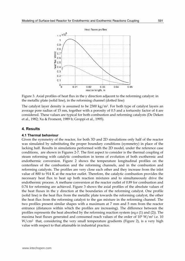
Modeling of Surface-bed Reactor for Endothermic and Exothermic Reactions Coupling
591
Figure 3 Axial profiles of heat flux in the y direction adjacent to the reforming catalyst in the metallic plate (solid line) in the reforming channel (dotted line)
The catalyst layer density is assumed to be 2300 kgm3 For both type of catalyst layers an average pore radius of 15 nm together with a porosity of 05 and a tortuosity factor of 4 are considered These values are typical for both combustion and reforming catalysts (De Deken et al 1982 Xu amp Froment 1989 b Groppi et al 1995)
4 Results
41 Thermal behaviour
Given the symmetry of the reactor for both 3D and 2D simulations only half of the reactor was simulated by substituting the proper boundary conditions (symmetry) in place of the lacking half Results in simulations performed with the 2D model under the reference case conditions are shown in Figures 2-7 The first aspect to consider is the thermal coupling of steam reforming with catalytic combustion in terms of evolution of both exothermic and endothermic conversion Figure 2 shows the temperature longitudinal profiles on the centerlines of the combustion and the reforming channels and in the combustion and reforming catalysts The profiles are very close each other and they increase from the inlet value of 800 to 914 K at the reactor outlet Therefore the catalytic combustion provides the necessary heat flux to heat up both reaction mixtures and to simultaneously drive the endothermic process A methane conversion at the reactor outlet of 089 for combustion and 074 for reforming are achieved Figure 3 shows the axial profiles of the absolute values of the heat fluxes in the y direction at the boundaries of the reforming catalyst One profile (solid line) is the heat flux from the metallic plate towards the reforming catalyst the other the heat flux from the reforming catalyst to the gas mixture in the reforming channel The two profiles present similar shapes with a maximum at 7 mm and 5 mm from the reactor entrance (distances within which the profiles are increasing) The difference between the profiles represents the heat absorbed by the reforming reaction system (eqs (1) and (2)) The maxima heat fluxes generated and consumed reach values of the order of 105 Wm2 ie 10 Wcm2 that considering the very small temperature gradients (Figure 2) is a very high value with respect to that attainable in industrial practice
wwwintechopencom
Recent Advances in Modelling and Simulation
592
a)
b)
Figure 4 Reactor temperature transverse profiles a at 15 cm from the reactor entrance b at 10 cm from the reactor outlet From 0 to 1 reforming channel From 1 to 12 reforming catalyst From 12 to 17 metallic plate From 17 to 19 combustion catalyst From 19 to 24 combustion channel
A further aspect to be examined is the magnitude of the transverse temperature gradients From Figure 2 it is already evident that the four profiles are very close each other However the transverse temperature gradients can be better analyzed from Figure 4 where the transverse temperature profiles at 15 cm (Figure 4a) from the reactor entrance and at 05 cm (Figure 4b) from the reactor outlet are shown In particular Figure 4a which pertains to the distance from the reactor inlet where the highest transverse temperature gradients develop evidences that the maximum temperature difference between reforming and combustion catalyst is 07 K while the maximum difference between the reforming and combustion channels is less than 10 K although that inside the reforming channel is almost 20 K Much lower differences can be observed close to the reactor outlet Specifically Figure 4b shows that the maximum temperature difference between reforming and combustion catalyst is 01 K that between the reforming and combustion channels is less than 1 K and that inside the reforming channel is almost 2 K As a result the high thermal conductivity of the metallic
wwwintechopencom
Modeling of Surface-bed Reactor for Endothermic and Exothermic Reactions Coupling
593
wall makes possible an efficient heat transfer at a temperature difference of the order of tenths of K With reference to Figure 4 it must be remarked that the value 0 of the transverse coordinate represents the centre of the reactor and the centre of the reforming channel Therefore at that point there is not a physical boundary the heat flux and the momentum flux are both zero and the x component of the gas velocity is maximum On the contrary the value 29 10-3 m of the transverse coordinate represents a solid wall that is the external boundary of the reactor and the boundary of the combustion channel This means that the heat flux is zero both components of the gas velocity are zero and the momentum flux is not zero This is one of the reasons because for the same distance in the transverse direction (y) the gas phase temperature difference in the reforming channel results always larger than that in the combustion channel (Figures 2 4a and 4b)
42 Mass transfer and chemical reactions
The concentration on the centerline of the reforming channel of the various species involved in the reactions occurring within the reforming catalyst are shown in Figure 5 This yields an overall picture of the reactor performance The hydrogen concentration steadily increases from the initial value to about 9 molm3 resulting the most abundant component in the exit gas mixture The ratio between the hydrogen concentration and CO concentration is very high (about 9)
Figure 5 Axial profiles of species concentrations on the centerline of the reforming channel
One important aspect to determine is the effect of interphase mass transport resistance Figure 6a shows the methane concentration axial profiles on the centerlines of the combustion channels and of the combustion catalyst while Figure 6b shows the correspondent profiles for the reforming section of the reactor From these Figures the differences between the channel and the catalyst profiles in each section yield a measure of the resistance to the interphase transport As expected in the combustion section the axial methane concentration profiles both in the channel and in the catalyst show an exponentially decreasing trend which reflects the relatively simple kinetics of the reaction In contrast a more complex trend is shown by the axial methane concentration profile in the catalyst because of the non linearity of the kinetics and the simultaneous occurrence of two
wwwintechopencom
Recent Advances in Modelling and Simulation
594
reactions (eqs (1) and (2)) Another aspect to examine is the size of the concentration gradients in the transverse direction These can be appreciated from Figure 7 where the transverse methane concentration profiles at 15 cm from the reactor inlet and at 05 cm from the reactor outlet are shown In particular the first profile which pertains to the distance from the reactor inlet where the highest transverse temperature gradients develops evidences that the gradients inside the reforming and the combustion channels are negligible with respect to the gradients in the catalyst phase The order of magnitude of these latter range from 105 molm4 close to the reactor inlet to 104 molm4 in the remaining part of the reforming catalyst and in all the combustion catalyst too
a)
b)
Figure 6 Axial methane concentration profiles along the reactor (a) solid line combustion channel dashed line combustion catalyst (b) solid line reforming channel dashed line reforming catalyst
wwwintechopencom
Modeling of Surface-bed Reactor for Endothermic and Exothermic Reactions Coupling
595
Figure 7 Methane concentration transverse profiles at 15 cm from the reactor entrance (solid line) and at 10 cm from the reactor outlet (dashed line) From 0 to 1 reforming channel From 1 to 12 reforming catalyst From 12 to 17 metallic plate From 17 to 19 combustion catalyst From 19 to 24 combustion channel
43 Methane concentration in the combustion channel
A basic requirement of the system in the object which is thought to be used for energy feeding of portable electric devices should be the complete reliability with respect to possible uncontrolled rises in temperature or even to a possible explosion hazard In this view the coordination between exothermic and endothermic reaction rates appears fundamental However even in the case such a coordination occurs the possible progress of the combustion reaction in the homogeneous phase may represent an hazard In addition if the concentration of the reacting mixture entering the combustion channel is within the flammability limits and the temperature becomes high enough it could ignite before the reactor inlet Therefore for safety purposes the occurrence of the exothermic reaction here represented by the methane combustion in the homogeneous phase should be avoided A possible way to make the system of hydrogen generation intrinsically safe is to feed the combustion mixture at a methane concentration below the LEL (lower explosivity limit) Considering that at STP the LEL of methane in air is about 5 vol that the autoignition temperature for airmethane mixtures is around 900 K the extimated LEL of methane in air at such a temperature should be about 3 vol (Crowl amp Louvar (2002)) Therefore a safe operating concentration should be about 3 vol To this purpose in this work beside those carried out under the conditions considered in the reference case other simulations were effected for which for a given methane mass flow rate its concentration at the combustion channel inlet was kept below 3 vol In this way the system is intrinsically safe because the reacting mixture cannot ignite spontaneously In addition the simulation becomes more realistic the contribution to the methane combustion of the homogeneous phase being really absent as implicitly hypothesized in this work
wwwintechopencom
Recent Advances in Modelling and Simulation
596
Figure 8 Temperature distribution over the boundaries of the 3D reactor
The comparison of results of runs performed under these conditions with those effected under the conditions of the reference case are reported in the following when analyzing the influence of various parameters on the reactor performance These simulations are labeled in the paper as n-expl in contrast to the others that are recalled as expl
44 Comparison between 2D and 3D results
For given operating conditions some simulations were carried out in both 2D and 3D geometry In principle a plane 2D geometry represents a slice of the reactor where the z dimension is greatly prevalent with respect to the y dimension Actually the model reactor has not such characteristics the length in the z dimension being 10 mm that is only 5 times the reforming channel width This means that the boundary effects due to the presence of the boundary walls in the z direction may have a significant influence on the velocity temperature and species concentration profiles that certainly influence the overall reactor performance Figures 8 shows the temperature distribution over the boundaries of the 3D reactor obtained under operating conditions of the reference case From this Figure the effect of the boundaries along the z direction appears evident
wwwintechopencom
Modeling of Surface-bed Reactor for Endothermic and Exothermic Reactions Coupling
597
Figure 9 Temperature space profiles along the reactor calculated with the 2D model (for the legend see caption to Figure 2)
Figure 10 Temperature space profiles along the reactor calculated with the 3D model (for the legend see caption to Figure 2)
Figures 9 and 10 show the reactor temperature longitudinal profiles on the centerlines of the combustion and the reforming channels and on the centerline of the combustion and reforming catalysts in the case of 2D and 3D geometry models respectively Both were calculated under the same operating conditions ie same inlet mass flow rates and compositions of the reference case (expl) but inlet temperature of 900 K In the case of the
wwwintechopencom
Recent Advances in Modelling and Simulation
598
3D simulation (Figure 10) the temperature profiles are those lying over a xy plane intersecting the reactor in the middle of its height along z The two sets of profiles appear quite similar the temperatures in the combustion section (catalyst and channel) are always slightly higher than the corresponding ones in the reforming section However a closer inspection reveals some significant differences In the 2D case the temperature after an initial slow growth increases steadily from 900 K at the reactor inlet up to 965 K at the reactor outlet while in the other case it grows faster reaches 960 K at 60 of the reactor length and remains constant up to the outlet Another difference is represented by the larger transverse temperature gradients of the 3D case with respect to 2D In the 2D case they are comparable with those observed in Figure 2 for the reference case while in the 3D case they are almost double This is true for all combinations ie catalyst-catalyst catalyst-channel and channel-channel On the whole the 3D case shows a faster progress of the reactions with consequent need for faster heat transfer These differences in the thermal behaviour between 2D and 3D simulations persist when the comparison is extended to other operating conditions and in addition they reflect the better overall performance of the 3D reactor with respect to the 2D as can be seen by the following discussion The quantitative comparison between the 2D and 3D simulations was made with respect to the main results ie the methane conversion in both the combustion and the steam reforming channels as obtained from equation 5 Further beside the methane conversions other parameters are employed ie a) the gas hourly space velocities GHSV in the combustion and steam reforming sides of the reactor calculated as ratio between gas flow rates at the reactor inlet temperature and volume of catalyst b) the maximum temperature reached in the reactor c) the mean gas residence time trm in both the combustion and the reforming channel calculated as ratio between the gas flow rates at the reactor inlet temperature and the volume of the channel and d) the hydrogen yield φH2 evaluated as ratio between the amounts of methane reacted and hydrogen produced GHSV and trm were useful to allow the comparison of simulations carried out by changing the catalyst volume or the channel width as discussed later Results of simulations carried out with the 2D and 3D models under various operating conditions are reported in Table 5 Those referring to the operating conditions of the reference case are listed in the first two rows of such a Table The other operating conditions are i) same inlet temperature of the reference case but different methane concentration in the combustion channel (3rd and 4th rows of Table 5) and ii) different inlet temperatures for the two conditions above (5th-8th rows of Table 5) Focusing the comparison on the results of the simulations in 2D and 3D with the same operating conditions it appears that in general the methane conversions at the reactor outlet calculated with the 2D geometry in both the combustion and reforming channels are lower than the correspondent in 3D geometry but in one case (Xch4-sr 3rd and 4th rows of the Table) This finding reflects the differences in the thermal behaviour discussed above In any case such conversions differ by less than 10 but in the last two rows of the Table where the differences are larger It is worth noting however that even in this case the values of the conversions are congruent with the overall results of the simulation For instance the lower value of Xch4-co in the 2D with respect to the correspondent in 3D results in a lower value of Xch4-sr and in a lower maximum temperature reached in the reactor
wwwintechopencom
Modeling of Surface-bed Reactor for Endothermic and Exothermic Reactions Coupling
599
Geometry Tin K
Xch4-co Xch4-sr Tmax K Trm-co ms
Trm-sr ms
GHSVco h-1
GHSVsr h-1
φH2
2D expl 800 089 074 914 0057 0026 314840 702884 329
3D expl 800 096 077 914 0057 0026 314840 702884 333
2D n-expl 800 036 045 827 0020 0026 900588 702884 344
3D n-expl 800 040 041 828 0020 0026 900588 702884 356
2D expl 900 095 090 965 0051 0023 354194 790745 305
3D expl 900 099 093 960 0051 0023 354194 790745 300
2D n-expl 900 049 069 900 0018 0023 1013162 790745 322
3D n-expl 900 068 079 920 0018 0023 1013162 790745 318
Table 5 Comparison of 2D and 3D results obtained under the same operating conditions
For what concerns the hydrogen yield focusing again the comparison on the results of the simulations in 2D and 3D at the same operating conditions data show that φH2rsquos obtained with the 2D geometry model are lower than that in 3D model but in one case (7th and 8th row of Table 5) It is worth noting that φH2=3 would be the stoichiometric value if reaction (1) were the only occurring in the reforming catalyst so that the amount exceeding 3 is due to the contribution of reaction (2) Data in Table 5 also shows the influence on the reactor performance of temperature and inlet methane concentration in the combustion channel In the case of inlet temperature of 900 K and methane concentration within the explosivity limits (case referring to results in Figures 9 and 10) the methane conversion is practically 1 (3D model) for the combustion reaction and very high for the reforming reactions However under these conditions the hydrogen yield is the lowest In contrast when the highest hydrogen yield is reached the lowest methane conversion is achieved Similar considerations can be done for the other results in the Table so that a general trend can be drawn from such results The higher the maximum temperature reached in the reactor the higher the methane conversions and the lower the hydrogen yield
45 Influence of the channels width
The reactor thermal behaviour and performance was studied for different channels width Wc at constant inlet flow rates of the reaction mixtures Runs were also carried out by keeping constant the mean inlet velocities of reaction mixtures The variation range for the combustion channels width Wc-co was 1-15 mm and for the reforming channel width Wc-sr 2-3 mm All other parameters were kept at their reference case values Keeping constant the inlet mass flow rates and altering the channel width results in modifying the inlet velocities in the reactor and consequently the mean residence time (trm) of the gases in the channels but the GHSVrsquos do not change The results in terms of methane conversions in the combustion and reforming channels are reported in Table 6 for the reference cases (3rd and 4th row in Table) and for cases where the methane concentration in the combustion channels were below the LEL (1st and 2nd row) At constant mass flow rates the influence of the channel width or better of trm appears negligible under n-expl conditions with a slight
wwwintechopencom
Recent Advances in Modelling and Simulation
600
prevalence of the reactor with narrower channels and weak under expl conditions with in contrast better performance for the reactor with wider channels Therefore it is not possible to draw conclusions
Wc-sr mm
Tin K
Xch4 -
co Xch4-sr
Tmax K
trm-co ms
trm-sr ms
GHSVco h-1
GHSVsr h-1
2 n-expl 800 036 045 827 0020 0026 900588 702884
3 n-expl 800 034 044 819 0030 0038 900588 702884
2 expl 800 089 074 914 0057 0026 314840 702884
3 expl 800 092 081 940 0086 0038 314840 702884
Vcost- 3 n-expl 800 022 033 800 0020 0026 1350882 1054327
Table 6 Comparison between reactor performance as a function of channel width
Unlike the previous case where inlet flow rates were kept constant an increase in channel width keeping the mean gas velocity and the value of trm constants affects significantly the outlet conversions In this case the amount of reactants flowing through the reactor per unit catalyst volume and then GHSV increases (compare 1st and 5th rows in Table 5) Increasing channel widths from their reference case value (Wc-sr = 2 mm and Wc-co= 1) at constant gas inlet velocity leads to methane conversion reduction because a) the catalyst amount becomes insufficient for the amount of reactants fed in the reactor and b) the external mass transfer resistances play a stronger role The overall reaction heat fluxes remain the same as channel width increases leaving a similar amount of sensible heat to be used for heating up larger amounts of reactants This results in lower temperatures along the reactor
46 Influence of catalyst thickness
The influence of catalyst thickness c on the reactor behaviour was studied by keeping constant the reactants mass flow rates The reactor operation was simulated for three values of catalyst thickness ie 200 100 and 50 microm while keeping all the other parameters at their reference case values but for what concerns the inlet methane concentration in the combustion channel that was at non explosive level This with respect to the reference case corresponds to decreasing GHSV of factors 2 and 4 respectively Changes in the catalyst thickness influence considerably both thermal behaviour and outlet conversions As above the comparison is made through the methane conversions achieved in the two cases both in the steam reforming and in the combustion channels The results are reported in Table 7 It is evident that the loss of performance due to a decrease of 50 of c from 200 to 100 μm is almost negligible This is mainly due to the conservative parameters used for defining the catalyst layer characteristics (ie mean pore radius and tortuosity) that results in a very impervious path for diffusing gases However when c is further decreased methane conversion both in the combustion and in the reforming section significantly decrease The hydrogen yield does not change too much within the limits of the three cases analyzed
wwwintechopencom
Modeling of Surface-bed Reactor for Endothermic and Exothermic Reactions Coupling
601
δc μm
Tin K Xch4 -co Xch4-sr Tmax Ktrm-co ms
trm-sr ms
GHSVco h-1
GHSVsr h-1
φH2
200 n-expl 800 036 045 827 0020 0026 900588 702884 344
100 n-expl 800 035 045 827 0020 0026 1801176 1405768 344
50 n-expl 800 027 038 800 0020 0026 3602352 2811536 342
Table 7 Comparison between reactor performance as a function of catalyst thickness
5 Discussion
As seen in the previous section (4) there are several operating parameters that influence the performances of the system They are typical of reacting systems and can be summarized as GHSVrsquos tmrrsquos and inlet gas temperatures The particularity of the present case is the simultaneous occurrence of two coupled reactions one exothermic and the other endothermic in which the extent of the second depends on the extent (heat produced) of the first and the effectiveness of the heat transferred In addition the coupling of the two reactions does not exclude to have for each set of values of the mentioned parameters pertaining to one reaction several sets of parameters for the other reaction This makes the system quite complex and difficult to analyze However some general considerations can be drawn
Figure 11 Methane conversions in the combustion and reforming sides of the reactor as a function of GHSV for various operating conditions available in Table 6 and 7
The first is that as expected GHVS plays a key role in determining the reactor performances although this is supported by only a part of the data For instance data in Table 7 pertaining to simulations of the influence of such a parameter carried out by changing GHSV in the same way for both sections of the reacting system shows a clear effect of GHSV the reactor
0 1000000 2000000 3000000 4000000
GHSV h-1
02
04
06
08
1
XC
H4
-co a
nd
XC
H4
-sr -
data from Table 7 comb side
data from Table 7 refor side
data from Table 6 comb side
data from Table 6 refor side
wwwintechopencom
Recent Advances in Modelling and Simulation
602
performance decreases as GHSV increases on both sides of the reactor Such an influence does not appear strong the conversion change being about 20 against GHSV variations of a factor 4 (Figure 11) The influence of GHSV is more evident from data in Table 6 pertaining to simulations of the influence of tmr In fact also in this case a clear trend appears and the influence even though in the same direction of the previous case appears much stronger since with respect to a GHSV change of about 20 the methane conversion varies by a factor 4 (Figure 11) Such a strong influence is due to the combined effect of tmr especially on the combustion side of the reactor (cfr Table 6) Instead for data in Table 5 pertaining to simulations of the reliability of 2D and 3D models and the effect of gas inlet temperature it is not possible to highlight a clear influence The comparison between the results obtained with the 2D and 3D models under the same operating conditions have evidenced differences in the performance of the reactor not large but significant When we move from 2D to 3D models such differences result in an increase from 5 to 20 of both Xch4-co and Xch4-sr which reflects a different thermal behavior of the reacting system and influence also the hydrogen yield It is worth noting that the computation time required in the two cases is very different Specifically using an HP xw8400workstation equipped with 2 Xeon processors and 4 GB of RAM a 2D simulation takes on the average about 20 minutes with respect to 50-60 hours necessary in the 3D case It is impossible by now to establish which is the more correct or the more reliable In particular it should be assessed if 2D simulations are suitable for purpose of reactor design and experimental data interpretation The answer should come from the comparison of the results of such simulations with experimental data obtained with a real reactor geometrically comparable operated under conditions as much as similar to those fixed for the simulations This represents argument for coming work of the authors Further interesting aspects to be studied are the simulation of unsteady-state conditions and specifically of the system start-up and of the system response to small changes in the gas feeding flow rates and temperatures
6 Conclusions
Methane steam reforming coupled with methane catalytic combustion by means of indirect heat transfer in a surface-bed catalytic reactor was studied by 2D and 3D models The reactor consists of a central reforming channel and two lateral combustion channels A reference case for what concerns operating conditions and reactor geometry was chosen and its simulation was carried out Changes of reactor performance as consequence of operating parameters and reactor geometry variations were analyzed with respect to the reference case The simulation showed that suitable amount of fuel and adequate catalyst activity in the combustion channel can provide enough heat to simultaneously heat up the reaction mixture and drive the endothermic process The proximity between the heat source and the heat sink increases the efficiency of heat transfer resulting in transverse temperature gradients do not exceeding generally 07 K across the metallic wall and 20 K across the gas in the channel Decrease of transverse temperature differences and intraphase mass transfer resistances have the global effect of reducing the reactor dimension and the catalyst amount The influence of channels width and catalyst layer thickness on reactor behaviour was also studied At constant inlet flow rates changes of channel width in the range 1ndash2 mm do not introduce significant differences in the reactor performance Rather small differences in the
wwwintechopencom
Modeling of Surface-bed Reactor for Endothermic and Exothermic Reactions Coupling
603
catalyst axial temperature profiles and outlet methane conversions are observed In contrast altering the channel width at constant inlet velocities has strong influence Larger channel width results in lower conversion and smoother axial temperature profiles Intraphase resistances are present even for catalyst thickness of micrometers for both reforming and combustion processes Increasing GHSV that is the inlet flow ratecatalyst volume ratio leads to lower outlet conversions Due to different effect of catalyst layer thickness on reforming and combustion channels there are significant changes in the reactor temperature profile Results indicate that steam reforming of methane in a surface-bed reactor is feasible provided that mass flow rates channels width catalyst loadings and thickness are properly designed
7 Notation
cp specific heat J(mol K) c concentration molm3 Deff effective diffusion coefficient m2s D molecular diffusion coefficient m2s GHSV gas hourly space velocity h-1 k thermal conductivity W(m K) or reaction rate constant Ke equilibrium constant M molecular weight kgmol LEL lower explosivity limit vol
unit vector perpendicular to the flux surface
N molar flux at the boundary mol(m2 s) p partial pressure bar P total pressure bar q thermal flux at the boundary J(m2 s) r reaction rate various dimensions (see eqs 1rsquo 2rsquo and 3rsquo) Rp catalyst pore radius nm STP standard temperature and pressure (298 K and 101 103 Pa) t time s T temperature K ts transverse surface ux Velocity component on the x coordinate
velocity vector
v normal component of velocity at the channel ingress x axial coordinate m X conversion y transverse coordinate m Wc distance between the reactor plates m z vertical coordinate m Greek letters ΔH0r heat of reaction at reference state conditions KJmol c catalyst thickness μm catalyst porosity φ atomic diffusion volume or chemical reaction yield
wwwintechopencom
Recent Advances in Modelling and Simulation
604
θ stoichiometric coefficient ρ density kgm3 τ catalyst tortuosity
Subscripts and superscripts cat catalyst co combustion CH4 methane H2 hydrogen in inlet i chemical species j channel k reaction l phase rm mean residence s metal sheet sr steam reforming 0 channel ingress 1 reforming reaction 2 water gas shift reaction 3 combustion reaction
8 Acknowledgements
The authors gratefully acknowledge the financial support of MIUR under grant PRIN ndeg 2006094333004
9 References
Akers WW amp Camp DP (1955) Kinetics of the methanendashsteam reaction AIChE Journal Vol 1 471ndash475 ISSN0001-1541
Allen DW Gerhard ER amp Likins Jr MR (1975) Kinetics of the MethanendashSteam Reaction Ind Eng Chem Proc Des Dev Vol 14 No 3 256-259 ISSN0196-4305
Aparicio L (1997) Transient Isotopic Studies and Microkinetic Modeling of Methane Reforming over Nickel Catalysts Journal of Catal Vol 165 No 2 262-274 ISSN 0021-9517
Avci AK Trimm DL amp İlsen Oumlnsan Z (2001) Heterogeneous reactor modeling for simulation of catalytic oxidation and steam reforming of methane Chem Eng Sci Vol 56 No 2 641-649 ISSN0009-2509
Bridger GW (1980) The steam reforming of hydrocarbons Catalysis Vol 3 39-69 ISSN0140-0568
Cao C Wang Y amp Rozmiarek RT (2005) Heterogeneous reactor model for steam reforming of methane in a microchannel reactor with microstructured catalysts Catal Today Vol 110 No 1-2 92ndash97 ISSN 0920-5861
Craciun R Shereck B amp Gorte RJ (1998) Kinetic studies of methane steam reforming on ceria-supported Pd Catal Lett Vol 51 No 3ndash4 149-153 ISSN 1011-372x
wwwintechopencom
Modeling of Surface-bed Reactor for Endothermic and Exothermic Reactions Coupling
605
Crowl DA amp Louvar JF (2002) Chemical Process Safety fundamentals with applications 2nd ed Prentice Hall PTR Upper Saddle River NJ USA ISBN 0-13mdash018176-5
De Deken J C Devos E F amp Froment G F (1982) Steam reforming of natural gas Intrinsic kinetics diffusional influences and reactor design ACS Symposium Series 196 181ndash197 ISSN0097-6156
Ehrfeld W amp Hessel V Lowe H (2000) Microreactor Wiley-VCH Verlag GmbH D-69469 ISBN Weinheim Germany
Gosiewski K (2001) Simulations of non-stationary reactors for catalytic conversion of methane to synthesis gas Chem Eng Sci Vol 56 No 4 1501-1510 ISSN
Groppi G Belloli A Tronconi E Forzatti P (1995) A comparison of lumped and distributed models of monolith catalytic combustors Chem Eng Sci Vol 50 No 17 2705ndash2715 ISSN0009-2509
Holladay JD Wang Y amp Jones E (2004) Review of Developments in Portable Hydrogen Production Using Microreactor Technology Chem Rev Vol 104 No 10 4767-4790 ISSN 0009-2665
Hou K amp Hughes R (2001) The kinetics of methane steam reforming over a Ni-Al2O3 catalyst Chem Eng Journal Vol 82 No 1-3 311-328 ISSN 1385-8947
Jamal Y amp Wyszynski M L (1994) On-board generation of hydrogen-rich gaseous fuels a review Int J of Hydrogen Energy Vol 19 No 7 557-572 ISSN 0360-3199
Jensen KF (2001) Microreaction engineering is small better Chem Eng Sci Vol 56 No 2 293-303 ISSN0009-2509
Kolios G Gritsch A Glo1ckler B amp Sorescu G (2004) Novel Reactor Concepts for Thermally Efficient Methane Steam Reforming Modeling and Simulation Ind Eng Chem Res Vol 43 No 16 4796-4808 ISSN0888-5885
Kruger P Blakeley J amp Leaver J (2003) Potential in New Zealand for use of hydrogen as a transportation fuel Int J of Hydrogen Energy Vol 28 No 8 795ndash802 ISSN 0360-3199
Kvamsdal HM Svendsen HF Hertzberg T amp Olsvik O (1999) Dynamic simulation and optimization of a catalytic steam reformer Chem Eng Sci Vol 54 No 13-14 2697-2706 ISSN0009-2509
Lerer M Duic N Alves LM amp Carvalho MG (2006) H2 RES energy planning tool for increasing the penetration of renewable energy sources in island energy supply In New and Renewable Technologies for Sustanaible Development MG Carvalho and NH Afgan (Ed s) 15-30 World Scientific ISBN 10 981-270-505-8 Singapore
Lerou JJ amp Ng KM (1996) Chemical reaction engineering A multiscale approach to a multiobjective task Chem Eng Sci Vol 51 No 10 1595-1614 ISSN0009-2509
Lincoln SF (2006) Challenged Earth ch7 Imperial College Press ISBN 1-86094-526-0 London
Loffler D G Faz C F Sokolovskii V amp Iglesia E (2002) Catalytic separator plate reactor and method of catalytic reforming of fuel to Hydrogen PCT Int Appl WO 0228769 A2
Luna C amp Becerra AM (1997) Kinetics of methane steam reforming on a Ni on alumina-titania catalyst React Kinet Catal Lett Vol 61 No 2 369-374 ISSN 0133-1736
Marschner F Renner HJ amp Boll W (2005) Electronic Encyclopedia Release 2005 7th ed in Ullmannrsquos Encyclopedia of Industrial Chemistry M Bohnet et al (Eds) Vol a12 John Wiley amp Sons ISBN-13 978-3-527-30385-4
wwwintechopencom
Recent Advances in Modelling and Simulation
606
Moore R B amp Raman V (1998) Hydrogen infrastructure for fuel cell transportation Int J of Hydrogen Energy Vol 23 No 7 617-620 ISSN 0360-3199
Perry RH amp Green DW (1999) Perrys Chemical Engineers Handbook (7th Ed) McGraw-Hill ISBN 0-07-049841-5
Robbins F A Zhu H amp Jackson GS (2003) Transient modeling of combined catalytic combustionCH4 steam reformng Catal Today Vol 83 No 1-4 141ndash156 ISSN 0920-5861
Rostrup-Nielsen JR Christiansen LJ amp BakHansen JH (1988) Activity of steam reforming catalysts Role and assessment Appl Catal Vol 43 No 2 287-303 ISSN0166-9834
Rostrup-Nielsen JR (1995) Innovation and the catalytic process industry - the science and challenge Chem Eng Sci Vol 50 No 24 4061-4071 ISSN0009-2509
Rostrup-Nielsen JR Dybkjaer I amp Coulthard GRG (2001) Topical Conf Proc AIChE Spring National Meeting Houston TX April Paper No 1
Rostrup-Nielsen JR (2004) Fuels and Energy for the Future The Role of Catalysis Catal Rev - Science and Engineering Vol 46 No 3ndash4 247-270 ISSN0161-4940
Schubert K Brandner J Fichtner M Linder G Schyhulla U amp Wenka A (2001) Microstructure devices for applications in thermal and chemical process engineering Microscale Thermophys Eng Vol 5 No 1 17-39 ISSN1089-3954
Tronconi E amp Groppi G (2000) A study on the thermal behavior of structured plate-type catalysts with metallic supports for gassolid exothermic reactions Chem Eng Sci Vol 55 Issue 24 December 6021-6036 ISSN0009-2509
Wang Y Johnson BR Cao C Chin Y Rozmiarek RT Gao Y Tonkovich AL (2005) Engineered catalysts for microchannel reactor applications In Microreactor Technology and Process Intensification Y Wang J Holladay (Eds) 65-73 ACS Symposium Series Vol 914 ISBN-13 9780841239234
Xu J amp Froment GF (1989a) Methane steam reforming II Diffusional limitations and reactor simulation AIChE Journal Vol 35 No 1 97-103 ISSN0001-1541
Xu J amp Froment GF (1989b) Methane steam reforming methanation and water-gas shift I Intrinsic kinetics AIChE Journal Vol 35 No 1 88-96 ISSN0001-1541
Zanfir M amp Gavriilidis A (2003) Catalytic Combustion Assisted Methane Steam Reforming Chem Eng Sci Vol 58 No 17 3947ndash 3960 ISSN0009-2509
wwwintechopencom
Modelling and SimulationEdited by Giuseppe Petrone and Giuliano Cammarata
ISBN 978-3-902613-25-7Hard cover 688 pagesPublisher I-Tech Education and PublishingPublished online 01 June 2008Published in print edition June 2008
InTech EuropeUniversity Campus STeP Ri Slavka Krautzeka 83A 51000 Rijeka Croatia Phone +385 (51) 770 447 Fax +385 (51) 686 166wwwintechopencom
InTech ChinaUnit 405 Office Block Hotel Equatorial Shanghai No65 Yan An Road (West) Shanghai 200040 China
Phone +86-21-62489820 Fax +86-21-62489821
This book collects original and innovative research studies concerning modeling and simulation of physicalsystems in a very wide range of applications encompassing micro-electro-mechanical systems measurementinstrumentations catalytic reactors biomechanical applications biological and chemical sensorsmagnetosensitive materials silicon photonic devices electronic devices optical fibers electro-microfluidicsystems composite materials fuel cells indoor air-conditioning systems active magnetic levitation systemsand more Some of the most recent numerical techniques as well as some of the software among the mostaccurate and sophisticated in treating complex systems are applied in order to exhaustively contribute inknowledge advances
How to referenceIn order to correctly reference this scholarly work feel free to copy and paste the following
Salvatore Vaccaro and Paolo Ciambelli (2008) Modeling of Surface-bed Reactor for Endothermic andExothermic Reactions Coupling Modelling and Simulation Giuseppe Petrone and Giuliano Cammarata (Ed)ISBN 978-3-902613-25-7 InTech Available fromhttpwwwintechopencombooksmodelling_and_simulationmodeling_of_surface-bed_reactor_for_endothermic_and_exothermic_reactions_coupling
copy 2008 The Author(s) Licensee IntechOpen This chapter is distributedunder the terms of the Creative Commons Attribution-NonCommercial-ShareAlike-30 License which permits use distribution and reproduction fornon-commercial purposes provided the original is properly cited andderivative works building on this content are distributed under the samelicense
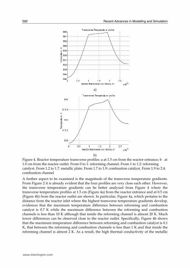
Recent Advances in Modelling and Simulation
592
a)
b)
Figure 4 Reactor temperature transverse profiles a at 15 cm from the reactor entrance b at 10 cm from the reactor outlet From 0 to 1 reforming channel From 1 to 12 reforming catalyst From 12 to 17 metallic plate From 17 to 19 combustion catalyst From 19 to 24 combustion channel
A further aspect to be examined is the magnitude of the transverse temperature gradients From Figure 2 it is already evident that the four profiles are very close each other However the transverse temperature gradients can be better analyzed from Figure 4 where the transverse temperature profiles at 15 cm (Figure 4a) from the reactor entrance and at 05 cm (Figure 4b) from the reactor outlet are shown In particular Figure 4a which pertains to the distance from the reactor inlet where the highest transverse temperature gradients develop evidences that the maximum temperature difference between reforming and combustion catalyst is 07 K while the maximum difference between the reforming and combustion channels is less than 10 K although that inside the reforming channel is almost 20 K Much lower differences can be observed close to the reactor outlet Specifically Figure 4b shows that the maximum temperature difference between reforming and combustion catalyst is 01 K that between the reforming and combustion channels is less than 1 K and that inside the reforming channel is almost 2 K As a result the high thermal conductivity of the metallic
wwwintechopencom
Modeling of Surface-bed Reactor for Endothermic and Exothermic Reactions Coupling
593
wall makes possible an efficient heat transfer at a temperature difference of the order of tenths of K With reference to Figure 4 it must be remarked that the value 0 of the transverse coordinate represents the centre of the reactor and the centre of the reforming channel Therefore at that point there is not a physical boundary the heat flux and the momentum flux are both zero and the x component of the gas velocity is maximum On the contrary the value 29 10-3 m of the transverse coordinate represents a solid wall that is the external boundary of the reactor and the boundary of the combustion channel This means that the heat flux is zero both components of the gas velocity are zero and the momentum flux is not zero This is one of the reasons because for the same distance in the transverse direction (y) the gas phase temperature difference in the reforming channel results always larger than that in the combustion channel (Figures 2 4a and 4b)
42 Mass transfer and chemical reactions
The concentration on the centerline of the reforming channel of the various species involved in the reactions occurring within the reforming catalyst are shown in Figure 5 This yields an overall picture of the reactor performance The hydrogen concentration steadily increases from the initial value to about 9 molm3 resulting the most abundant component in the exit gas mixture The ratio between the hydrogen concentration and CO concentration is very high (about 9)
Figure 5 Axial profiles of species concentrations on the centerline of the reforming channel
One important aspect to determine is the effect of interphase mass transport resistance Figure 6a shows the methane concentration axial profiles on the centerlines of the combustion channels and of the combustion catalyst while Figure 6b shows the correspondent profiles for the reforming section of the reactor From these Figures the differences between the channel and the catalyst profiles in each section yield a measure of the resistance to the interphase transport As expected in the combustion section the axial methane concentration profiles both in the channel and in the catalyst show an exponentially decreasing trend which reflects the relatively simple kinetics of the reaction In contrast a more complex trend is shown by the axial methane concentration profile in the catalyst because of the non linearity of the kinetics and the simultaneous occurrence of two
wwwintechopencom
Recent Advances in Modelling and Simulation
594
reactions (eqs (1) and (2)) Another aspect to examine is the size of the concentration gradients in the transverse direction These can be appreciated from Figure 7 where the transverse methane concentration profiles at 15 cm from the reactor inlet and at 05 cm from the reactor outlet are shown In particular the first profile which pertains to the distance from the reactor inlet where the highest transverse temperature gradients develops evidences that the gradients inside the reforming and the combustion channels are negligible with respect to the gradients in the catalyst phase The order of magnitude of these latter range from 105 molm4 close to the reactor inlet to 104 molm4 in the remaining part of the reforming catalyst and in all the combustion catalyst too
a)
b)
Figure 6 Axial methane concentration profiles along the reactor (a) solid line combustion channel dashed line combustion catalyst (b) solid line reforming channel dashed line reforming catalyst
wwwintechopencom
Modeling of Surface-bed Reactor for Endothermic and Exothermic Reactions Coupling
595
Figure 7 Methane concentration transverse profiles at 15 cm from the reactor entrance (solid line) and at 10 cm from the reactor outlet (dashed line) From 0 to 1 reforming channel From 1 to 12 reforming catalyst From 12 to 17 metallic plate From 17 to 19 combustion catalyst From 19 to 24 combustion channel
43 Methane concentration in the combustion channel
A basic requirement of the system in the object which is thought to be used for energy feeding of portable electric devices should be the complete reliability with respect to possible uncontrolled rises in temperature or even to a possible explosion hazard In this view the coordination between exothermic and endothermic reaction rates appears fundamental However even in the case such a coordination occurs the possible progress of the combustion reaction in the homogeneous phase may represent an hazard In addition if the concentration of the reacting mixture entering the combustion channel is within the flammability limits and the temperature becomes high enough it could ignite before the reactor inlet Therefore for safety purposes the occurrence of the exothermic reaction here represented by the methane combustion in the homogeneous phase should be avoided A possible way to make the system of hydrogen generation intrinsically safe is to feed the combustion mixture at a methane concentration below the LEL (lower explosivity limit) Considering that at STP the LEL of methane in air is about 5 vol that the autoignition temperature for airmethane mixtures is around 900 K the extimated LEL of methane in air at such a temperature should be about 3 vol (Crowl amp Louvar (2002)) Therefore a safe operating concentration should be about 3 vol To this purpose in this work beside those carried out under the conditions considered in the reference case other simulations were effected for which for a given methane mass flow rate its concentration at the combustion channel inlet was kept below 3 vol In this way the system is intrinsically safe because the reacting mixture cannot ignite spontaneously In addition the simulation becomes more realistic the contribution to the methane combustion of the homogeneous phase being really absent as implicitly hypothesized in this work
wwwintechopencom
Recent Advances in Modelling and Simulation
596
Figure 8 Temperature distribution over the boundaries of the 3D reactor
The comparison of results of runs performed under these conditions with those effected under the conditions of the reference case are reported in the following when analyzing the influence of various parameters on the reactor performance These simulations are labeled in the paper as n-expl in contrast to the others that are recalled as expl
44 Comparison between 2D and 3D results
For given operating conditions some simulations were carried out in both 2D and 3D geometry In principle a plane 2D geometry represents a slice of the reactor where the z dimension is greatly prevalent with respect to the y dimension Actually the model reactor has not such characteristics the length in the z dimension being 10 mm that is only 5 times the reforming channel width This means that the boundary effects due to the presence of the boundary walls in the z direction may have a significant influence on the velocity temperature and species concentration profiles that certainly influence the overall reactor performance Figures 8 shows the temperature distribution over the boundaries of the 3D reactor obtained under operating conditions of the reference case From this Figure the effect of the boundaries along the z direction appears evident
wwwintechopencom
Modeling of Surface-bed Reactor for Endothermic and Exothermic Reactions Coupling
597
Figure 9 Temperature space profiles along the reactor calculated with the 2D model (for the legend see caption to Figure 2)
Figure 10 Temperature space profiles along the reactor calculated with the 3D model (for the legend see caption to Figure 2)
Figures 9 and 10 show the reactor temperature longitudinal profiles on the centerlines of the combustion and the reforming channels and on the centerline of the combustion and reforming catalysts in the case of 2D and 3D geometry models respectively Both were calculated under the same operating conditions ie same inlet mass flow rates and compositions of the reference case (expl) but inlet temperature of 900 K In the case of the
wwwintechopencom
Recent Advances in Modelling and Simulation
598
3D simulation (Figure 10) the temperature profiles are those lying over a xy plane intersecting the reactor in the middle of its height along z The two sets of profiles appear quite similar the temperatures in the combustion section (catalyst and channel) are always slightly higher than the corresponding ones in the reforming section However a closer inspection reveals some significant differences In the 2D case the temperature after an initial slow growth increases steadily from 900 K at the reactor inlet up to 965 K at the reactor outlet while in the other case it grows faster reaches 960 K at 60 of the reactor length and remains constant up to the outlet Another difference is represented by the larger transverse temperature gradients of the 3D case with respect to 2D In the 2D case they are comparable with those observed in Figure 2 for the reference case while in the 3D case they are almost double This is true for all combinations ie catalyst-catalyst catalyst-channel and channel-channel On the whole the 3D case shows a faster progress of the reactions with consequent need for faster heat transfer These differences in the thermal behaviour between 2D and 3D simulations persist when the comparison is extended to other operating conditions and in addition they reflect the better overall performance of the 3D reactor with respect to the 2D as can be seen by the following discussion The quantitative comparison between the 2D and 3D simulations was made with respect to the main results ie the methane conversion in both the combustion and the steam reforming channels as obtained from equation 5 Further beside the methane conversions other parameters are employed ie a) the gas hourly space velocities GHSV in the combustion and steam reforming sides of the reactor calculated as ratio between gas flow rates at the reactor inlet temperature and volume of catalyst b) the maximum temperature reached in the reactor c) the mean gas residence time trm in both the combustion and the reforming channel calculated as ratio between the gas flow rates at the reactor inlet temperature and the volume of the channel and d) the hydrogen yield φH2 evaluated as ratio between the amounts of methane reacted and hydrogen produced GHSV and trm were useful to allow the comparison of simulations carried out by changing the catalyst volume or the channel width as discussed later Results of simulations carried out with the 2D and 3D models under various operating conditions are reported in Table 5 Those referring to the operating conditions of the reference case are listed in the first two rows of such a Table The other operating conditions are i) same inlet temperature of the reference case but different methane concentration in the combustion channel (3rd and 4th rows of Table 5) and ii) different inlet temperatures for the two conditions above (5th-8th rows of Table 5) Focusing the comparison on the results of the simulations in 2D and 3D with the same operating conditions it appears that in general the methane conversions at the reactor outlet calculated with the 2D geometry in both the combustion and reforming channels are lower than the correspondent in 3D geometry but in one case (Xch4-sr 3rd and 4th rows of the Table) This finding reflects the differences in the thermal behaviour discussed above In any case such conversions differ by less than 10 but in the last two rows of the Table where the differences are larger It is worth noting however that even in this case the values of the conversions are congruent with the overall results of the simulation For instance the lower value of Xch4-co in the 2D with respect to the correspondent in 3D results in a lower value of Xch4-sr and in a lower maximum temperature reached in the reactor
wwwintechopencom
Modeling of Surface-bed Reactor for Endothermic and Exothermic Reactions Coupling
599
Geometry Tin K
Xch4-co Xch4-sr Tmax K Trm-co ms
Trm-sr ms
GHSVco h-1
GHSVsr h-1
φH2
2D expl 800 089 074 914 0057 0026 314840 702884 329
3D expl 800 096 077 914 0057 0026 314840 702884 333
2D n-expl 800 036 045 827 0020 0026 900588 702884 344
3D n-expl 800 040 041 828 0020 0026 900588 702884 356
2D expl 900 095 090 965 0051 0023 354194 790745 305
3D expl 900 099 093 960 0051 0023 354194 790745 300
2D n-expl 900 049 069 900 0018 0023 1013162 790745 322
3D n-expl 900 068 079 920 0018 0023 1013162 790745 318
Table 5 Comparison of 2D and 3D results obtained under the same operating conditions
For what concerns the hydrogen yield focusing again the comparison on the results of the simulations in 2D and 3D at the same operating conditions data show that φH2rsquos obtained with the 2D geometry model are lower than that in 3D model but in one case (7th and 8th row of Table 5) It is worth noting that φH2=3 would be the stoichiometric value if reaction (1) were the only occurring in the reforming catalyst so that the amount exceeding 3 is due to the contribution of reaction (2) Data in Table 5 also shows the influence on the reactor performance of temperature and inlet methane concentration in the combustion channel In the case of inlet temperature of 900 K and methane concentration within the explosivity limits (case referring to results in Figures 9 and 10) the methane conversion is practically 1 (3D model) for the combustion reaction and very high for the reforming reactions However under these conditions the hydrogen yield is the lowest In contrast when the highest hydrogen yield is reached the lowest methane conversion is achieved Similar considerations can be done for the other results in the Table so that a general trend can be drawn from such results The higher the maximum temperature reached in the reactor the higher the methane conversions and the lower the hydrogen yield
45 Influence of the channels width
The reactor thermal behaviour and performance was studied for different channels width Wc at constant inlet flow rates of the reaction mixtures Runs were also carried out by keeping constant the mean inlet velocities of reaction mixtures The variation range for the combustion channels width Wc-co was 1-15 mm and for the reforming channel width Wc-sr 2-3 mm All other parameters were kept at their reference case values Keeping constant the inlet mass flow rates and altering the channel width results in modifying the inlet velocities in the reactor and consequently the mean residence time (trm) of the gases in the channels but the GHSVrsquos do not change The results in terms of methane conversions in the combustion and reforming channels are reported in Table 6 for the reference cases (3rd and 4th row in Table) and for cases where the methane concentration in the combustion channels were below the LEL (1st and 2nd row) At constant mass flow rates the influence of the channel width or better of trm appears negligible under n-expl conditions with a slight
wwwintechopencom
Recent Advances in Modelling and Simulation
600
prevalence of the reactor with narrower channels and weak under expl conditions with in contrast better performance for the reactor with wider channels Therefore it is not possible to draw conclusions
Wc-sr mm
Tin K
Xch4 -
co Xch4-sr
Tmax K
trm-co ms
trm-sr ms
GHSVco h-1
GHSVsr h-1
2 n-expl 800 036 045 827 0020 0026 900588 702884
3 n-expl 800 034 044 819 0030 0038 900588 702884
2 expl 800 089 074 914 0057 0026 314840 702884
3 expl 800 092 081 940 0086 0038 314840 702884
Vcost- 3 n-expl 800 022 033 800 0020 0026 1350882 1054327
Table 6 Comparison between reactor performance as a function of channel width
Unlike the previous case where inlet flow rates were kept constant an increase in channel width keeping the mean gas velocity and the value of trm constants affects significantly the outlet conversions In this case the amount of reactants flowing through the reactor per unit catalyst volume and then GHSV increases (compare 1st and 5th rows in Table 5) Increasing channel widths from their reference case value (Wc-sr = 2 mm and Wc-co= 1) at constant gas inlet velocity leads to methane conversion reduction because a) the catalyst amount becomes insufficient for the amount of reactants fed in the reactor and b) the external mass transfer resistances play a stronger role The overall reaction heat fluxes remain the same as channel width increases leaving a similar amount of sensible heat to be used for heating up larger amounts of reactants This results in lower temperatures along the reactor
46 Influence of catalyst thickness
The influence of catalyst thickness c on the reactor behaviour was studied by keeping constant the reactants mass flow rates The reactor operation was simulated for three values of catalyst thickness ie 200 100 and 50 microm while keeping all the other parameters at their reference case values but for what concerns the inlet methane concentration in the combustion channel that was at non explosive level This with respect to the reference case corresponds to decreasing GHSV of factors 2 and 4 respectively Changes in the catalyst thickness influence considerably both thermal behaviour and outlet conversions As above the comparison is made through the methane conversions achieved in the two cases both in the steam reforming and in the combustion channels The results are reported in Table 7 It is evident that the loss of performance due to a decrease of 50 of c from 200 to 100 μm is almost negligible This is mainly due to the conservative parameters used for defining the catalyst layer characteristics (ie mean pore radius and tortuosity) that results in a very impervious path for diffusing gases However when c is further decreased methane conversion both in the combustion and in the reforming section significantly decrease The hydrogen yield does not change too much within the limits of the three cases analyzed
wwwintechopencom
Modeling of Surface-bed Reactor for Endothermic and Exothermic Reactions Coupling
601
δc μm
Tin K Xch4 -co Xch4-sr Tmax Ktrm-co ms
trm-sr ms
GHSVco h-1
GHSVsr h-1
φH2
200 n-expl 800 036 045 827 0020 0026 900588 702884 344
100 n-expl 800 035 045 827 0020 0026 1801176 1405768 344
50 n-expl 800 027 038 800 0020 0026 3602352 2811536 342
Table 7 Comparison between reactor performance as a function of catalyst thickness
5 Discussion
As seen in the previous section (4) there are several operating parameters that influence the performances of the system They are typical of reacting systems and can be summarized as GHSVrsquos tmrrsquos and inlet gas temperatures The particularity of the present case is the simultaneous occurrence of two coupled reactions one exothermic and the other endothermic in which the extent of the second depends on the extent (heat produced) of the first and the effectiveness of the heat transferred In addition the coupling of the two reactions does not exclude to have for each set of values of the mentioned parameters pertaining to one reaction several sets of parameters for the other reaction This makes the system quite complex and difficult to analyze However some general considerations can be drawn
Figure 11 Methane conversions in the combustion and reforming sides of the reactor as a function of GHSV for various operating conditions available in Table 6 and 7
The first is that as expected GHVS plays a key role in determining the reactor performances although this is supported by only a part of the data For instance data in Table 7 pertaining to simulations of the influence of such a parameter carried out by changing GHSV in the same way for both sections of the reacting system shows a clear effect of GHSV the reactor
0 1000000 2000000 3000000 4000000
GHSV h-1
02
04
06
08
1
XC
H4
-co a
nd
XC
H4
-sr -
data from Table 7 comb side
data from Table 7 refor side
data from Table 6 comb side
data from Table 6 refor side
wwwintechopencom
Recent Advances in Modelling and Simulation
602
performance decreases as GHSV increases on both sides of the reactor Such an influence does not appear strong the conversion change being about 20 against GHSV variations of a factor 4 (Figure 11) The influence of GHSV is more evident from data in Table 6 pertaining to simulations of the influence of tmr In fact also in this case a clear trend appears and the influence even though in the same direction of the previous case appears much stronger since with respect to a GHSV change of about 20 the methane conversion varies by a factor 4 (Figure 11) Such a strong influence is due to the combined effect of tmr especially on the combustion side of the reactor (cfr Table 6) Instead for data in Table 5 pertaining to simulations of the reliability of 2D and 3D models and the effect of gas inlet temperature it is not possible to highlight a clear influence The comparison between the results obtained with the 2D and 3D models under the same operating conditions have evidenced differences in the performance of the reactor not large but significant When we move from 2D to 3D models such differences result in an increase from 5 to 20 of both Xch4-co and Xch4-sr which reflects a different thermal behavior of the reacting system and influence also the hydrogen yield It is worth noting that the computation time required in the two cases is very different Specifically using an HP xw8400workstation equipped with 2 Xeon processors and 4 GB of RAM a 2D simulation takes on the average about 20 minutes with respect to 50-60 hours necessary in the 3D case It is impossible by now to establish which is the more correct or the more reliable In particular it should be assessed if 2D simulations are suitable for purpose of reactor design and experimental data interpretation The answer should come from the comparison of the results of such simulations with experimental data obtained with a real reactor geometrically comparable operated under conditions as much as similar to those fixed for the simulations This represents argument for coming work of the authors Further interesting aspects to be studied are the simulation of unsteady-state conditions and specifically of the system start-up and of the system response to small changes in the gas feeding flow rates and temperatures
6 Conclusions
Methane steam reforming coupled with methane catalytic combustion by means of indirect heat transfer in a surface-bed catalytic reactor was studied by 2D and 3D models The reactor consists of a central reforming channel and two lateral combustion channels A reference case for what concerns operating conditions and reactor geometry was chosen and its simulation was carried out Changes of reactor performance as consequence of operating parameters and reactor geometry variations were analyzed with respect to the reference case The simulation showed that suitable amount of fuel and adequate catalyst activity in the combustion channel can provide enough heat to simultaneously heat up the reaction mixture and drive the endothermic process The proximity between the heat source and the heat sink increases the efficiency of heat transfer resulting in transverse temperature gradients do not exceeding generally 07 K across the metallic wall and 20 K across the gas in the channel Decrease of transverse temperature differences and intraphase mass transfer resistances have the global effect of reducing the reactor dimension and the catalyst amount The influence of channels width and catalyst layer thickness on reactor behaviour was also studied At constant inlet flow rates changes of channel width in the range 1ndash2 mm do not introduce significant differences in the reactor performance Rather small differences in the
wwwintechopencom
Modeling of Surface-bed Reactor for Endothermic and Exothermic Reactions Coupling
603
catalyst axial temperature profiles and outlet methane conversions are observed In contrast altering the channel width at constant inlet velocities has strong influence Larger channel width results in lower conversion and smoother axial temperature profiles Intraphase resistances are present even for catalyst thickness of micrometers for both reforming and combustion processes Increasing GHSV that is the inlet flow ratecatalyst volume ratio leads to lower outlet conversions Due to different effect of catalyst layer thickness on reforming and combustion channels there are significant changes in the reactor temperature profile Results indicate that steam reforming of methane in a surface-bed reactor is feasible provided that mass flow rates channels width catalyst loadings and thickness are properly designed
7 Notation
cp specific heat J(mol K) c concentration molm3 Deff effective diffusion coefficient m2s D molecular diffusion coefficient m2s GHSV gas hourly space velocity h-1 k thermal conductivity W(m K) or reaction rate constant Ke equilibrium constant M molecular weight kgmol LEL lower explosivity limit vol
unit vector perpendicular to the flux surface
N molar flux at the boundary mol(m2 s) p partial pressure bar P total pressure bar q thermal flux at the boundary J(m2 s) r reaction rate various dimensions (see eqs 1rsquo 2rsquo and 3rsquo) Rp catalyst pore radius nm STP standard temperature and pressure (298 K and 101 103 Pa) t time s T temperature K ts transverse surface ux Velocity component on the x coordinate
velocity vector
v normal component of velocity at the channel ingress x axial coordinate m X conversion y transverse coordinate m Wc distance between the reactor plates m z vertical coordinate m Greek letters ΔH0r heat of reaction at reference state conditions KJmol c catalyst thickness μm catalyst porosity φ atomic diffusion volume or chemical reaction yield
wwwintechopencom
Recent Advances in Modelling and Simulation
604
θ stoichiometric coefficient ρ density kgm3 τ catalyst tortuosity
Subscripts and superscripts cat catalyst co combustion CH4 methane H2 hydrogen in inlet i chemical species j channel k reaction l phase rm mean residence s metal sheet sr steam reforming 0 channel ingress 1 reforming reaction 2 water gas shift reaction 3 combustion reaction
8 Acknowledgements
The authors gratefully acknowledge the financial support of MIUR under grant PRIN ndeg 2006094333004
9 References
Akers WW amp Camp DP (1955) Kinetics of the methanendashsteam reaction AIChE Journal Vol 1 471ndash475 ISSN0001-1541
Allen DW Gerhard ER amp Likins Jr MR (1975) Kinetics of the MethanendashSteam Reaction Ind Eng Chem Proc Des Dev Vol 14 No 3 256-259 ISSN0196-4305
Aparicio L (1997) Transient Isotopic Studies and Microkinetic Modeling of Methane Reforming over Nickel Catalysts Journal of Catal Vol 165 No 2 262-274 ISSN 0021-9517
Avci AK Trimm DL amp İlsen Oumlnsan Z (2001) Heterogeneous reactor modeling for simulation of catalytic oxidation and steam reforming of methane Chem Eng Sci Vol 56 No 2 641-649 ISSN0009-2509
Bridger GW (1980) The steam reforming of hydrocarbons Catalysis Vol 3 39-69 ISSN0140-0568
Cao C Wang Y amp Rozmiarek RT (2005) Heterogeneous reactor model for steam reforming of methane in a microchannel reactor with microstructured catalysts Catal Today Vol 110 No 1-2 92ndash97 ISSN 0920-5861
Craciun R Shereck B amp Gorte RJ (1998) Kinetic studies of methane steam reforming on ceria-supported Pd Catal Lett Vol 51 No 3ndash4 149-153 ISSN 1011-372x
wwwintechopencom
Modeling of Surface-bed Reactor for Endothermic and Exothermic Reactions Coupling
605
Crowl DA amp Louvar JF (2002) Chemical Process Safety fundamentals with applications 2nd ed Prentice Hall PTR Upper Saddle River NJ USA ISBN 0-13mdash018176-5
De Deken J C Devos E F amp Froment G F (1982) Steam reforming of natural gas Intrinsic kinetics diffusional influences and reactor design ACS Symposium Series 196 181ndash197 ISSN0097-6156
Ehrfeld W amp Hessel V Lowe H (2000) Microreactor Wiley-VCH Verlag GmbH D-69469 ISBN Weinheim Germany
Gosiewski K (2001) Simulations of non-stationary reactors for catalytic conversion of methane to synthesis gas Chem Eng Sci Vol 56 No 4 1501-1510 ISSN
Groppi G Belloli A Tronconi E Forzatti P (1995) A comparison of lumped and distributed models of monolith catalytic combustors Chem Eng Sci Vol 50 No 17 2705ndash2715 ISSN0009-2509
Holladay JD Wang Y amp Jones E (2004) Review of Developments in Portable Hydrogen Production Using Microreactor Technology Chem Rev Vol 104 No 10 4767-4790 ISSN 0009-2665
Hou K amp Hughes R (2001) The kinetics of methane steam reforming over a Ni-Al2O3 catalyst Chem Eng Journal Vol 82 No 1-3 311-328 ISSN 1385-8947
Jamal Y amp Wyszynski M L (1994) On-board generation of hydrogen-rich gaseous fuels a review Int J of Hydrogen Energy Vol 19 No 7 557-572 ISSN 0360-3199
Jensen KF (2001) Microreaction engineering is small better Chem Eng Sci Vol 56 No 2 293-303 ISSN0009-2509
Kolios G Gritsch A Glo1ckler B amp Sorescu G (2004) Novel Reactor Concepts for Thermally Efficient Methane Steam Reforming Modeling and Simulation Ind Eng Chem Res Vol 43 No 16 4796-4808 ISSN0888-5885
Kruger P Blakeley J amp Leaver J (2003) Potential in New Zealand for use of hydrogen as a transportation fuel Int J of Hydrogen Energy Vol 28 No 8 795ndash802 ISSN 0360-3199
Kvamsdal HM Svendsen HF Hertzberg T amp Olsvik O (1999) Dynamic simulation and optimization of a catalytic steam reformer Chem Eng Sci Vol 54 No 13-14 2697-2706 ISSN0009-2509
Lerer M Duic N Alves LM amp Carvalho MG (2006) H2 RES energy planning tool for increasing the penetration of renewable energy sources in island energy supply In New and Renewable Technologies for Sustanaible Development MG Carvalho and NH Afgan (Ed s) 15-30 World Scientific ISBN 10 981-270-505-8 Singapore
Lerou JJ amp Ng KM (1996) Chemical reaction engineering A multiscale approach to a multiobjective task Chem Eng Sci Vol 51 No 10 1595-1614 ISSN0009-2509
Lincoln SF (2006) Challenged Earth ch7 Imperial College Press ISBN 1-86094-526-0 London
Loffler D G Faz C F Sokolovskii V amp Iglesia E (2002) Catalytic separator plate reactor and method of catalytic reforming of fuel to Hydrogen PCT Int Appl WO 0228769 A2
Luna C amp Becerra AM (1997) Kinetics of methane steam reforming on a Ni on alumina-titania catalyst React Kinet Catal Lett Vol 61 No 2 369-374 ISSN 0133-1736
Marschner F Renner HJ amp Boll W (2005) Electronic Encyclopedia Release 2005 7th ed in Ullmannrsquos Encyclopedia of Industrial Chemistry M Bohnet et al (Eds) Vol a12 John Wiley amp Sons ISBN-13 978-3-527-30385-4
wwwintechopencom
Recent Advances in Modelling and Simulation
606
Moore R B amp Raman V (1998) Hydrogen infrastructure for fuel cell transportation Int J of Hydrogen Energy Vol 23 No 7 617-620 ISSN 0360-3199
Perry RH amp Green DW (1999) Perrys Chemical Engineers Handbook (7th Ed) McGraw-Hill ISBN 0-07-049841-5
Robbins F A Zhu H amp Jackson GS (2003) Transient modeling of combined catalytic combustionCH4 steam reformng Catal Today Vol 83 No 1-4 141ndash156 ISSN 0920-5861
Rostrup-Nielsen JR Christiansen LJ amp BakHansen JH (1988) Activity of steam reforming catalysts Role and assessment Appl Catal Vol 43 No 2 287-303 ISSN0166-9834
Rostrup-Nielsen JR (1995) Innovation and the catalytic process industry - the science and challenge Chem Eng Sci Vol 50 No 24 4061-4071 ISSN0009-2509
Rostrup-Nielsen JR Dybkjaer I amp Coulthard GRG (2001) Topical Conf Proc AIChE Spring National Meeting Houston TX April Paper No 1
Rostrup-Nielsen JR (2004) Fuels and Energy for the Future The Role of Catalysis Catal Rev - Science and Engineering Vol 46 No 3ndash4 247-270 ISSN0161-4940
Schubert K Brandner J Fichtner M Linder G Schyhulla U amp Wenka A (2001) Microstructure devices for applications in thermal and chemical process engineering Microscale Thermophys Eng Vol 5 No 1 17-39 ISSN1089-3954
Tronconi E amp Groppi G (2000) A study on the thermal behavior of structured plate-type catalysts with metallic supports for gassolid exothermic reactions Chem Eng Sci Vol 55 Issue 24 December 6021-6036 ISSN0009-2509
Wang Y Johnson BR Cao C Chin Y Rozmiarek RT Gao Y Tonkovich AL (2005) Engineered catalysts for microchannel reactor applications In Microreactor Technology and Process Intensification Y Wang J Holladay (Eds) 65-73 ACS Symposium Series Vol 914 ISBN-13 9780841239234
Xu J amp Froment GF (1989a) Methane steam reforming II Diffusional limitations and reactor simulation AIChE Journal Vol 35 No 1 97-103 ISSN0001-1541
Xu J amp Froment GF (1989b) Methane steam reforming methanation and water-gas shift I Intrinsic kinetics AIChE Journal Vol 35 No 1 88-96 ISSN0001-1541
Zanfir M amp Gavriilidis A (2003) Catalytic Combustion Assisted Methane Steam Reforming Chem Eng Sci Vol 58 No 17 3947ndash 3960 ISSN0009-2509
wwwintechopencom
Modelling and SimulationEdited by Giuseppe Petrone and Giuliano Cammarata
ISBN 978-3-902613-25-7Hard cover 688 pagesPublisher I-Tech Education and PublishingPublished online 01 June 2008Published in print edition June 2008
InTech EuropeUniversity Campus STeP Ri Slavka Krautzeka 83A 51000 Rijeka Croatia Phone +385 (51) 770 447 Fax +385 (51) 686 166wwwintechopencom
InTech ChinaUnit 405 Office Block Hotel Equatorial Shanghai No65 Yan An Road (West) Shanghai 200040 China
Phone +86-21-62489820 Fax +86-21-62489821
This book collects original and innovative research studies concerning modeling and simulation of physicalsystems in a very wide range of applications encompassing micro-electro-mechanical systems measurementinstrumentations catalytic reactors biomechanical applications biological and chemical sensorsmagnetosensitive materials silicon photonic devices electronic devices optical fibers electro-microfluidicsystems composite materials fuel cells indoor air-conditioning systems active magnetic levitation systemsand more Some of the most recent numerical techniques as well as some of the software among the mostaccurate and sophisticated in treating complex systems are applied in order to exhaustively contribute inknowledge advances
How to referenceIn order to correctly reference this scholarly work feel free to copy and paste the following
Salvatore Vaccaro and Paolo Ciambelli (2008) Modeling of Surface-bed Reactor for Endothermic andExothermic Reactions Coupling Modelling and Simulation Giuseppe Petrone and Giuliano Cammarata (Ed)ISBN 978-3-902613-25-7 InTech Available fromhttpwwwintechopencombooksmodelling_and_simulationmodeling_of_surface-bed_reactor_for_endothermic_and_exothermic_reactions_coupling
copy 2008 The Author(s) Licensee IntechOpen This chapter is distributedunder the terms of the Creative Commons Attribution-NonCommercial-ShareAlike-30 License which permits use distribution and reproduction fornon-commercial purposes provided the original is properly cited andderivative works building on this content are distributed under the samelicense
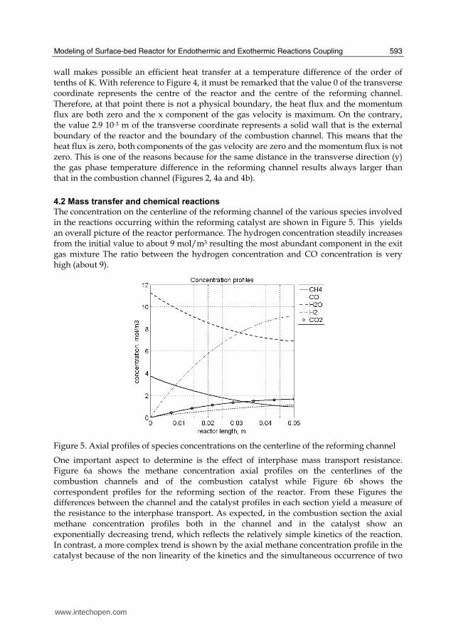
Modeling of Surface-bed Reactor for Endothermic and Exothermic Reactions Coupling
593
wall makes possible an efficient heat transfer at a temperature difference of the order of tenths of K With reference to Figure 4 it must be remarked that the value 0 of the transverse coordinate represents the centre of the reactor and the centre of the reforming channel Therefore at that point there is not a physical boundary the heat flux and the momentum flux are both zero and the x component of the gas velocity is maximum On the contrary the value 29 10-3 m of the transverse coordinate represents a solid wall that is the external boundary of the reactor and the boundary of the combustion channel This means that the heat flux is zero both components of the gas velocity are zero and the momentum flux is not zero This is one of the reasons because for the same distance in the transverse direction (y) the gas phase temperature difference in the reforming channel results always larger than that in the combustion channel (Figures 2 4a and 4b)
42 Mass transfer and chemical reactions
The concentration on the centerline of the reforming channel of the various species involved in the reactions occurring within the reforming catalyst are shown in Figure 5 This yields an overall picture of the reactor performance The hydrogen concentration steadily increases from the initial value to about 9 molm3 resulting the most abundant component in the exit gas mixture The ratio between the hydrogen concentration and CO concentration is very high (about 9)
Figure 5 Axial profiles of species concentrations on the centerline of the reforming channel
One important aspect to determine is the effect of interphase mass transport resistance Figure 6a shows the methane concentration axial profiles on the centerlines of the combustion channels and of the combustion catalyst while Figure 6b shows the correspondent profiles for the reforming section of the reactor From these Figures the differences between the channel and the catalyst profiles in each section yield a measure of the resistance to the interphase transport As expected in the combustion section the axial methane concentration profiles both in the channel and in the catalyst show an exponentially decreasing trend which reflects the relatively simple kinetics of the reaction In contrast a more complex trend is shown by the axial methane concentration profile in the catalyst because of the non linearity of the kinetics and the simultaneous occurrence of two
wwwintechopencom
Recent Advances in Modelling and Simulation
594
reactions (eqs (1) and (2)) Another aspect to examine is the size of the concentration gradients in the transverse direction These can be appreciated from Figure 7 where the transverse methane concentration profiles at 15 cm from the reactor inlet and at 05 cm from the reactor outlet are shown In particular the first profile which pertains to the distance from the reactor inlet where the highest transverse temperature gradients develops evidences that the gradients inside the reforming and the combustion channels are negligible with respect to the gradients in the catalyst phase The order of magnitude of these latter range from 105 molm4 close to the reactor inlet to 104 molm4 in the remaining part of the reforming catalyst and in all the combustion catalyst too
a)
b)
Figure 6 Axial methane concentration profiles along the reactor (a) solid line combustion channel dashed line combustion catalyst (b) solid line reforming channel dashed line reforming catalyst
wwwintechopencom
Modeling of Surface-bed Reactor for Endothermic and Exothermic Reactions Coupling
595
Figure 7 Methane concentration transverse profiles at 15 cm from the reactor entrance (solid line) and at 10 cm from the reactor outlet (dashed line) From 0 to 1 reforming channel From 1 to 12 reforming catalyst From 12 to 17 metallic plate From 17 to 19 combustion catalyst From 19 to 24 combustion channel
43 Methane concentration in the combustion channel
A basic requirement of the system in the object which is thought to be used for energy feeding of portable electric devices should be the complete reliability with respect to possible uncontrolled rises in temperature or even to a possible explosion hazard In this view the coordination between exothermic and endothermic reaction rates appears fundamental However even in the case such a coordination occurs the possible progress of the combustion reaction in the homogeneous phase may represent an hazard In addition if the concentration of the reacting mixture entering the combustion channel is within the flammability limits and the temperature becomes high enough it could ignite before the reactor inlet Therefore for safety purposes the occurrence of the exothermic reaction here represented by the methane combustion in the homogeneous phase should be avoided A possible way to make the system of hydrogen generation intrinsically safe is to feed the combustion mixture at a methane concentration below the LEL (lower explosivity limit) Considering that at STP the LEL of methane in air is about 5 vol that the autoignition temperature for airmethane mixtures is around 900 K the extimated LEL of methane in air at such a temperature should be about 3 vol (Crowl amp Louvar (2002)) Therefore a safe operating concentration should be about 3 vol To this purpose in this work beside those carried out under the conditions considered in the reference case other simulations were effected for which for a given methane mass flow rate its concentration at the combustion channel inlet was kept below 3 vol In this way the system is intrinsically safe because the reacting mixture cannot ignite spontaneously In addition the simulation becomes more realistic the contribution to the methane combustion of the homogeneous phase being really absent as implicitly hypothesized in this work
wwwintechopencom
Recent Advances in Modelling and Simulation
596
Figure 8 Temperature distribution over the boundaries of the 3D reactor
The comparison of results of runs performed under these conditions with those effected under the conditions of the reference case are reported in the following when analyzing the influence of various parameters on the reactor performance These simulations are labeled in the paper as n-expl in contrast to the others that are recalled as expl
44 Comparison between 2D and 3D results
For given operating conditions some simulations were carried out in both 2D and 3D geometry In principle a plane 2D geometry represents a slice of the reactor where the z dimension is greatly prevalent with respect to the y dimension Actually the model reactor has not such characteristics the length in the z dimension being 10 mm that is only 5 times the reforming channel width This means that the boundary effects due to the presence of the boundary walls in the z direction may have a significant influence on the velocity temperature and species concentration profiles that certainly influence the overall reactor performance Figures 8 shows the temperature distribution over the boundaries of the 3D reactor obtained under operating conditions of the reference case From this Figure the effect of the boundaries along the z direction appears evident
wwwintechopencom
Modeling of Surface-bed Reactor for Endothermic and Exothermic Reactions Coupling
597
Figure 9 Temperature space profiles along the reactor calculated with the 2D model (for the legend see caption to Figure 2)
Figure 10 Temperature space profiles along the reactor calculated with the 3D model (for the legend see caption to Figure 2)
Figures 9 and 10 show the reactor temperature longitudinal profiles on the centerlines of the combustion and the reforming channels and on the centerline of the combustion and reforming catalysts in the case of 2D and 3D geometry models respectively Both were calculated under the same operating conditions ie same inlet mass flow rates and compositions of the reference case (expl) but inlet temperature of 900 K In the case of the
wwwintechopencom
Recent Advances in Modelling and Simulation
598
3D simulation (Figure 10) the temperature profiles are those lying over a xy plane intersecting the reactor in the middle of its height along z The two sets of profiles appear quite similar the temperatures in the combustion section (catalyst and channel) are always slightly higher than the corresponding ones in the reforming section However a closer inspection reveals some significant differences In the 2D case the temperature after an initial slow growth increases steadily from 900 K at the reactor inlet up to 965 K at the reactor outlet while in the other case it grows faster reaches 960 K at 60 of the reactor length and remains constant up to the outlet Another difference is represented by the larger transverse temperature gradients of the 3D case with respect to 2D In the 2D case they are comparable with those observed in Figure 2 for the reference case while in the 3D case they are almost double This is true for all combinations ie catalyst-catalyst catalyst-channel and channel-channel On the whole the 3D case shows a faster progress of the reactions with consequent need for faster heat transfer These differences in the thermal behaviour between 2D and 3D simulations persist when the comparison is extended to other operating conditions and in addition they reflect the better overall performance of the 3D reactor with respect to the 2D as can be seen by the following discussion The quantitative comparison between the 2D and 3D simulations was made with respect to the main results ie the methane conversion in both the combustion and the steam reforming channels as obtained from equation 5 Further beside the methane conversions other parameters are employed ie a) the gas hourly space velocities GHSV in the combustion and steam reforming sides of the reactor calculated as ratio between gas flow rates at the reactor inlet temperature and volume of catalyst b) the maximum temperature reached in the reactor c) the mean gas residence time trm in both the combustion and the reforming channel calculated as ratio between the gas flow rates at the reactor inlet temperature and the volume of the channel and d) the hydrogen yield φH2 evaluated as ratio between the amounts of methane reacted and hydrogen produced GHSV and trm were useful to allow the comparison of simulations carried out by changing the catalyst volume or the channel width as discussed later Results of simulations carried out with the 2D and 3D models under various operating conditions are reported in Table 5 Those referring to the operating conditions of the reference case are listed in the first two rows of such a Table The other operating conditions are i) same inlet temperature of the reference case but different methane concentration in the combustion channel (3rd and 4th rows of Table 5) and ii) different inlet temperatures for the two conditions above (5th-8th rows of Table 5) Focusing the comparison on the results of the simulations in 2D and 3D with the same operating conditions it appears that in general the methane conversions at the reactor outlet calculated with the 2D geometry in both the combustion and reforming channels are lower than the correspondent in 3D geometry but in one case (Xch4-sr 3rd and 4th rows of the Table) This finding reflects the differences in the thermal behaviour discussed above In any case such conversions differ by less than 10 but in the last two rows of the Table where the differences are larger It is worth noting however that even in this case the values of the conversions are congruent with the overall results of the simulation For instance the lower value of Xch4-co in the 2D with respect to the correspondent in 3D results in a lower value of Xch4-sr and in a lower maximum temperature reached in the reactor
wwwintechopencom
Modeling of Surface-bed Reactor for Endothermic and Exothermic Reactions Coupling
599
Geometry Tin K
Xch4-co Xch4-sr Tmax K Trm-co ms
Trm-sr ms
GHSVco h-1
GHSVsr h-1
φH2
2D expl 800 089 074 914 0057 0026 314840 702884 329
3D expl 800 096 077 914 0057 0026 314840 702884 333
2D n-expl 800 036 045 827 0020 0026 900588 702884 344
3D n-expl 800 040 041 828 0020 0026 900588 702884 356
2D expl 900 095 090 965 0051 0023 354194 790745 305
3D expl 900 099 093 960 0051 0023 354194 790745 300
2D n-expl 900 049 069 900 0018 0023 1013162 790745 322
3D n-expl 900 068 079 920 0018 0023 1013162 790745 318
Table 5 Comparison of 2D and 3D results obtained under the same operating conditions
For what concerns the hydrogen yield focusing again the comparison on the results of the simulations in 2D and 3D at the same operating conditions data show that φH2rsquos obtained with the 2D geometry model are lower than that in 3D model but in one case (7th and 8th row of Table 5) It is worth noting that φH2=3 would be the stoichiometric value if reaction (1) were the only occurring in the reforming catalyst so that the amount exceeding 3 is due to the contribution of reaction (2) Data in Table 5 also shows the influence on the reactor performance of temperature and inlet methane concentration in the combustion channel In the case of inlet temperature of 900 K and methane concentration within the explosivity limits (case referring to results in Figures 9 and 10) the methane conversion is practically 1 (3D model) for the combustion reaction and very high for the reforming reactions However under these conditions the hydrogen yield is the lowest In contrast when the highest hydrogen yield is reached the lowest methane conversion is achieved Similar considerations can be done for the other results in the Table so that a general trend can be drawn from such results The higher the maximum temperature reached in the reactor the higher the methane conversions and the lower the hydrogen yield
45 Influence of the channels width
The reactor thermal behaviour and performance was studied for different channels width Wc at constant inlet flow rates of the reaction mixtures Runs were also carried out by keeping constant the mean inlet velocities of reaction mixtures The variation range for the combustion channels width Wc-co was 1-15 mm and for the reforming channel width Wc-sr 2-3 mm All other parameters were kept at their reference case values Keeping constant the inlet mass flow rates and altering the channel width results in modifying the inlet velocities in the reactor and consequently the mean residence time (trm) of the gases in the channels but the GHSVrsquos do not change The results in terms of methane conversions in the combustion and reforming channels are reported in Table 6 for the reference cases (3rd and 4th row in Table) and for cases where the methane concentration in the combustion channels were below the LEL (1st and 2nd row) At constant mass flow rates the influence of the channel width or better of trm appears negligible under n-expl conditions with a slight
wwwintechopencom
Recent Advances in Modelling and Simulation
600
prevalence of the reactor with narrower channels and weak under expl conditions with in contrast better performance for the reactor with wider channels Therefore it is not possible to draw conclusions
Wc-sr mm
Tin K
Xch4 -
co Xch4-sr
Tmax K
trm-co ms
trm-sr ms
GHSVco h-1
GHSVsr h-1
2 n-expl 800 036 045 827 0020 0026 900588 702884
3 n-expl 800 034 044 819 0030 0038 900588 702884
2 expl 800 089 074 914 0057 0026 314840 702884
3 expl 800 092 081 940 0086 0038 314840 702884
Vcost- 3 n-expl 800 022 033 800 0020 0026 1350882 1054327
Table 6 Comparison between reactor performance as a function of channel width
Unlike the previous case where inlet flow rates were kept constant an increase in channel width keeping the mean gas velocity and the value of trm constants affects significantly the outlet conversions In this case the amount of reactants flowing through the reactor per unit catalyst volume and then GHSV increases (compare 1st and 5th rows in Table 5) Increasing channel widths from their reference case value (Wc-sr = 2 mm and Wc-co= 1) at constant gas inlet velocity leads to methane conversion reduction because a) the catalyst amount becomes insufficient for the amount of reactants fed in the reactor and b) the external mass transfer resistances play a stronger role The overall reaction heat fluxes remain the same as channel width increases leaving a similar amount of sensible heat to be used for heating up larger amounts of reactants This results in lower temperatures along the reactor
46 Influence of catalyst thickness
The influence of catalyst thickness c on the reactor behaviour was studied by keeping constant the reactants mass flow rates The reactor operation was simulated for three values of catalyst thickness ie 200 100 and 50 microm while keeping all the other parameters at their reference case values but for what concerns the inlet methane concentration in the combustion channel that was at non explosive level This with respect to the reference case corresponds to decreasing GHSV of factors 2 and 4 respectively Changes in the catalyst thickness influence considerably both thermal behaviour and outlet conversions As above the comparison is made through the methane conversions achieved in the two cases both in the steam reforming and in the combustion channels The results are reported in Table 7 It is evident that the loss of performance due to a decrease of 50 of c from 200 to 100 μm is almost negligible This is mainly due to the conservative parameters used for defining the catalyst layer characteristics (ie mean pore radius and tortuosity) that results in a very impervious path for diffusing gases However when c is further decreased methane conversion both in the combustion and in the reforming section significantly decrease The hydrogen yield does not change too much within the limits of the three cases analyzed
wwwintechopencom
Modeling of Surface-bed Reactor for Endothermic and Exothermic Reactions Coupling
601
δc μm
Tin K Xch4 -co Xch4-sr Tmax Ktrm-co ms
trm-sr ms
GHSVco h-1
GHSVsr h-1
φH2
200 n-expl 800 036 045 827 0020 0026 900588 702884 344
100 n-expl 800 035 045 827 0020 0026 1801176 1405768 344
50 n-expl 800 027 038 800 0020 0026 3602352 2811536 342
Table 7 Comparison between reactor performance as a function of catalyst thickness
5 Discussion
As seen in the previous section (4) there are several operating parameters that influence the performances of the system They are typical of reacting systems and can be summarized as GHSVrsquos tmrrsquos and inlet gas temperatures The particularity of the present case is the simultaneous occurrence of two coupled reactions one exothermic and the other endothermic in which the extent of the second depends on the extent (heat produced) of the first and the effectiveness of the heat transferred In addition the coupling of the two reactions does not exclude to have for each set of values of the mentioned parameters pertaining to one reaction several sets of parameters for the other reaction This makes the system quite complex and difficult to analyze However some general considerations can be drawn
Figure 11 Methane conversions in the combustion and reforming sides of the reactor as a function of GHSV for various operating conditions available in Table 6 and 7
The first is that as expected GHVS plays a key role in determining the reactor performances although this is supported by only a part of the data For instance data in Table 7 pertaining to simulations of the influence of such a parameter carried out by changing GHSV in the same way for both sections of the reacting system shows a clear effect of GHSV the reactor
0 1000000 2000000 3000000 4000000
GHSV h-1
02
04
06
08
1
XC
H4
-co a
nd
XC
H4
-sr -
data from Table 7 comb side
data from Table 7 refor side
data from Table 6 comb side
data from Table 6 refor side
wwwintechopencom
Recent Advances in Modelling and Simulation
602
performance decreases as GHSV increases on both sides of the reactor Such an influence does not appear strong the conversion change being about 20 against GHSV variations of a factor 4 (Figure 11) The influence of GHSV is more evident from data in Table 6 pertaining to simulations of the influence of tmr In fact also in this case a clear trend appears and the influence even though in the same direction of the previous case appears much stronger since with respect to a GHSV change of about 20 the methane conversion varies by a factor 4 (Figure 11) Such a strong influence is due to the combined effect of tmr especially on the combustion side of the reactor (cfr Table 6) Instead for data in Table 5 pertaining to simulations of the reliability of 2D and 3D models and the effect of gas inlet temperature it is not possible to highlight a clear influence The comparison between the results obtained with the 2D and 3D models under the same operating conditions have evidenced differences in the performance of the reactor not large but significant When we move from 2D to 3D models such differences result in an increase from 5 to 20 of both Xch4-co and Xch4-sr which reflects a different thermal behavior of the reacting system and influence also the hydrogen yield It is worth noting that the computation time required in the two cases is very different Specifically using an HP xw8400workstation equipped with 2 Xeon processors and 4 GB of RAM a 2D simulation takes on the average about 20 minutes with respect to 50-60 hours necessary in the 3D case It is impossible by now to establish which is the more correct or the more reliable In particular it should be assessed if 2D simulations are suitable for purpose of reactor design and experimental data interpretation The answer should come from the comparison of the results of such simulations with experimental data obtained with a real reactor geometrically comparable operated under conditions as much as similar to those fixed for the simulations This represents argument for coming work of the authors Further interesting aspects to be studied are the simulation of unsteady-state conditions and specifically of the system start-up and of the system response to small changes in the gas feeding flow rates and temperatures
6 Conclusions
Methane steam reforming coupled with methane catalytic combustion by means of indirect heat transfer in a surface-bed catalytic reactor was studied by 2D and 3D models The reactor consists of a central reforming channel and two lateral combustion channels A reference case for what concerns operating conditions and reactor geometry was chosen and its simulation was carried out Changes of reactor performance as consequence of operating parameters and reactor geometry variations were analyzed with respect to the reference case The simulation showed that suitable amount of fuel and adequate catalyst activity in the combustion channel can provide enough heat to simultaneously heat up the reaction mixture and drive the endothermic process The proximity between the heat source and the heat sink increases the efficiency of heat transfer resulting in transverse temperature gradients do not exceeding generally 07 K across the metallic wall and 20 K across the gas in the channel Decrease of transverse temperature differences and intraphase mass transfer resistances have the global effect of reducing the reactor dimension and the catalyst amount The influence of channels width and catalyst layer thickness on reactor behaviour was also studied At constant inlet flow rates changes of channel width in the range 1ndash2 mm do not introduce significant differences in the reactor performance Rather small differences in the
wwwintechopencom
Modeling of Surface-bed Reactor for Endothermic and Exothermic Reactions Coupling
603
catalyst axial temperature profiles and outlet methane conversions are observed In contrast altering the channel width at constant inlet velocities has strong influence Larger channel width results in lower conversion and smoother axial temperature profiles Intraphase resistances are present even for catalyst thickness of micrometers for both reforming and combustion processes Increasing GHSV that is the inlet flow ratecatalyst volume ratio leads to lower outlet conversions Due to different effect of catalyst layer thickness on reforming and combustion channels there are significant changes in the reactor temperature profile Results indicate that steam reforming of methane in a surface-bed reactor is feasible provided that mass flow rates channels width catalyst loadings and thickness are properly designed
7 Notation
cp specific heat J(mol K) c concentration molm3 Deff effective diffusion coefficient m2s D molecular diffusion coefficient m2s GHSV gas hourly space velocity h-1 k thermal conductivity W(m K) or reaction rate constant Ke equilibrium constant M molecular weight kgmol LEL lower explosivity limit vol
unit vector perpendicular to the flux surface
N molar flux at the boundary mol(m2 s) p partial pressure bar P total pressure bar q thermal flux at the boundary J(m2 s) r reaction rate various dimensions (see eqs 1rsquo 2rsquo and 3rsquo) Rp catalyst pore radius nm STP standard temperature and pressure (298 K and 101 103 Pa) t time s T temperature K ts transverse surface ux Velocity component on the x coordinate
velocity vector
v normal component of velocity at the channel ingress x axial coordinate m X conversion y transverse coordinate m Wc distance between the reactor plates m z vertical coordinate m Greek letters ΔH0r heat of reaction at reference state conditions KJmol c catalyst thickness μm catalyst porosity φ atomic diffusion volume or chemical reaction yield
wwwintechopencom
Recent Advances in Modelling and Simulation
604
θ stoichiometric coefficient ρ density kgm3 τ catalyst tortuosity
Subscripts and superscripts cat catalyst co combustion CH4 methane H2 hydrogen in inlet i chemical species j channel k reaction l phase rm mean residence s metal sheet sr steam reforming 0 channel ingress 1 reforming reaction 2 water gas shift reaction 3 combustion reaction
8 Acknowledgements
The authors gratefully acknowledge the financial support of MIUR under grant PRIN ndeg 2006094333004
9 References
Akers WW amp Camp DP (1955) Kinetics of the methanendashsteam reaction AIChE Journal Vol 1 471ndash475 ISSN0001-1541
Allen DW Gerhard ER amp Likins Jr MR (1975) Kinetics of the MethanendashSteam Reaction Ind Eng Chem Proc Des Dev Vol 14 No 3 256-259 ISSN0196-4305
Aparicio L (1997) Transient Isotopic Studies and Microkinetic Modeling of Methane Reforming over Nickel Catalysts Journal of Catal Vol 165 No 2 262-274 ISSN 0021-9517
Avci AK Trimm DL amp İlsen Oumlnsan Z (2001) Heterogeneous reactor modeling for simulation of catalytic oxidation and steam reforming of methane Chem Eng Sci Vol 56 No 2 641-649 ISSN0009-2509
Bridger GW (1980) The steam reforming of hydrocarbons Catalysis Vol 3 39-69 ISSN0140-0568
Cao C Wang Y amp Rozmiarek RT (2005) Heterogeneous reactor model for steam reforming of methane in a microchannel reactor with microstructured catalysts Catal Today Vol 110 No 1-2 92ndash97 ISSN 0920-5861
Craciun R Shereck B amp Gorte RJ (1998) Kinetic studies of methane steam reforming on ceria-supported Pd Catal Lett Vol 51 No 3ndash4 149-153 ISSN 1011-372x
wwwintechopencom
Modeling of Surface-bed Reactor for Endothermic and Exothermic Reactions Coupling
605
Crowl DA amp Louvar JF (2002) Chemical Process Safety fundamentals with applications 2nd ed Prentice Hall PTR Upper Saddle River NJ USA ISBN 0-13mdash018176-5
De Deken J C Devos E F amp Froment G F (1982) Steam reforming of natural gas Intrinsic kinetics diffusional influences and reactor design ACS Symposium Series 196 181ndash197 ISSN0097-6156
Ehrfeld W amp Hessel V Lowe H (2000) Microreactor Wiley-VCH Verlag GmbH D-69469 ISBN Weinheim Germany
Gosiewski K (2001) Simulations of non-stationary reactors for catalytic conversion of methane to synthesis gas Chem Eng Sci Vol 56 No 4 1501-1510 ISSN
Groppi G Belloli A Tronconi E Forzatti P (1995) A comparison of lumped and distributed models of monolith catalytic combustors Chem Eng Sci Vol 50 No 17 2705ndash2715 ISSN0009-2509
Holladay JD Wang Y amp Jones E (2004) Review of Developments in Portable Hydrogen Production Using Microreactor Technology Chem Rev Vol 104 No 10 4767-4790 ISSN 0009-2665
Hou K amp Hughes R (2001) The kinetics of methane steam reforming over a Ni-Al2O3 catalyst Chem Eng Journal Vol 82 No 1-3 311-328 ISSN 1385-8947
Jamal Y amp Wyszynski M L (1994) On-board generation of hydrogen-rich gaseous fuels a review Int J of Hydrogen Energy Vol 19 No 7 557-572 ISSN 0360-3199
Jensen KF (2001) Microreaction engineering is small better Chem Eng Sci Vol 56 No 2 293-303 ISSN0009-2509
Kolios G Gritsch A Glo1ckler B amp Sorescu G (2004) Novel Reactor Concepts for Thermally Efficient Methane Steam Reforming Modeling and Simulation Ind Eng Chem Res Vol 43 No 16 4796-4808 ISSN0888-5885
Kruger P Blakeley J amp Leaver J (2003) Potential in New Zealand for use of hydrogen as a transportation fuel Int J of Hydrogen Energy Vol 28 No 8 795ndash802 ISSN 0360-3199
Kvamsdal HM Svendsen HF Hertzberg T amp Olsvik O (1999) Dynamic simulation and optimization of a catalytic steam reformer Chem Eng Sci Vol 54 No 13-14 2697-2706 ISSN0009-2509
Lerer M Duic N Alves LM amp Carvalho MG (2006) H2 RES energy planning tool for increasing the penetration of renewable energy sources in island energy supply In New and Renewable Technologies for Sustanaible Development MG Carvalho and NH Afgan (Ed s) 15-30 World Scientific ISBN 10 981-270-505-8 Singapore
Lerou JJ amp Ng KM (1996) Chemical reaction engineering A multiscale approach to a multiobjective task Chem Eng Sci Vol 51 No 10 1595-1614 ISSN0009-2509
Lincoln SF (2006) Challenged Earth ch7 Imperial College Press ISBN 1-86094-526-0 London
Loffler D G Faz C F Sokolovskii V amp Iglesia E (2002) Catalytic separator plate reactor and method of catalytic reforming of fuel to Hydrogen PCT Int Appl WO 0228769 A2
Luna C amp Becerra AM (1997) Kinetics of methane steam reforming on a Ni on alumina-titania catalyst React Kinet Catal Lett Vol 61 No 2 369-374 ISSN 0133-1736
Marschner F Renner HJ amp Boll W (2005) Electronic Encyclopedia Release 2005 7th ed in Ullmannrsquos Encyclopedia of Industrial Chemistry M Bohnet et al (Eds) Vol a12 John Wiley amp Sons ISBN-13 978-3-527-30385-4
wwwintechopencom
Recent Advances in Modelling and Simulation
606
Moore R B amp Raman V (1998) Hydrogen infrastructure for fuel cell transportation Int J of Hydrogen Energy Vol 23 No 7 617-620 ISSN 0360-3199
Perry RH amp Green DW (1999) Perrys Chemical Engineers Handbook (7th Ed) McGraw-Hill ISBN 0-07-049841-5
Robbins F A Zhu H amp Jackson GS (2003) Transient modeling of combined catalytic combustionCH4 steam reformng Catal Today Vol 83 No 1-4 141ndash156 ISSN 0920-5861
Rostrup-Nielsen JR Christiansen LJ amp BakHansen JH (1988) Activity of steam reforming catalysts Role and assessment Appl Catal Vol 43 No 2 287-303 ISSN0166-9834
Rostrup-Nielsen JR (1995) Innovation and the catalytic process industry - the science and challenge Chem Eng Sci Vol 50 No 24 4061-4071 ISSN0009-2509
Rostrup-Nielsen JR Dybkjaer I amp Coulthard GRG (2001) Topical Conf Proc AIChE Spring National Meeting Houston TX April Paper No 1
Rostrup-Nielsen JR (2004) Fuels and Energy for the Future The Role of Catalysis Catal Rev - Science and Engineering Vol 46 No 3ndash4 247-270 ISSN0161-4940
Schubert K Brandner J Fichtner M Linder G Schyhulla U amp Wenka A (2001) Microstructure devices for applications in thermal and chemical process engineering Microscale Thermophys Eng Vol 5 No 1 17-39 ISSN1089-3954
Tronconi E amp Groppi G (2000) A study on the thermal behavior of structured plate-type catalysts with metallic supports for gassolid exothermic reactions Chem Eng Sci Vol 55 Issue 24 December 6021-6036 ISSN0009-2509
Wang Y Johnson BR Cao C Chin Y Rozmiarek RT Gao Y Tonkovich AL (2005) Engineered catalysts for microchannel reactor applications In Microreactor Technology and Process Intensification Y Wang J Holladay (Eds) 65-73 ACS Symposium Series Vol 914 ISBN-13 9780841239234
Xu J amp Froment GF (1989a) Methane steam reforming II Diffusional limitations and reactor simulation AIChE Journal Vol 35 No 1 97-103 ISSN0001-1541
Xu J amp Froment GF (1989b) Methane steam reforming methanation and water-gas shift I Intrinsic kinetics AIChE Journal Vol 35 No 1 88-96 ISSN0001-1541
Zanfir M amp Gavriilidis A (2003) Catalytic Combustion Assisted Methane Steam Reforming Chem Eng Sci Vol 58 No 17 3947ndash 3960 ISSN0009-2509
wwwintechopencom
Modelling and SimulationEdited by Giuseppe Petrone and Giuliano Cammarata
ISBN 978-3-902613-25-7Hard cover 688 pagesPublisher I-Tech Education and PublishingPublished online 01 June 2008Published in print edition June 2008
InTech EuropeUniversity Campus STeP Ri Slavka Krautzeka 83A 51000 Rijeka Croatia Phone +385 (51) 770 447 Fax +385 (51) 686 166wwwintechopencom
InTech ChinaUnit 405 Office Block Hotel Equatorial Shanghai No65 Yan An Road (West) Shanghai 200040 China
Phone +86-21-62489820 Fax +86-21-62489821
This book collects original and innovative research studies concerning modeling and simulation of physicalsystems in a very wide range of applications encompassing micro-electro-mechanical systems measurementinstrumentations catalytic reactors biomechanical applications biological and chemical sensorsmagnetosensitive materials silicon photonic devices electronic devices optical fibers electro-microfluidicsystems composite materials fuel cells indoor air-conditioning systems active magnetic levitation systemsand more Some of the most recent numerical techniques as well as some of the software among the mostaccurate and sophisticated in treating complex systems are applied in order to exhaustively contribute inknowledge advances
How to referenceIn order to correctly reference this scholarly work feel free to copy and paste the following
Salvatore Vaccaro and Paolo Ciambelli (2008) Modeling of Surface-bed Reactor for Endothermic andExothermic Reactions Coupling Modelling and Simulation Giuseppe Petrone and Giuliano Cammarata (Ed)ISBN 978-3-902613-25-7 InTech Available fromhttpwwwintechopencombooksmodelling_and_simulationmodeling_of_surface-bed_reactor_for_endothermic_and_exothermic_reactions_coupling
copy 2008 The Author(s) Licensee IntechOpen This chapter is distributedunder the terms of the Creative Commons Attribution-NonCommercial-ShareAlike-30 License which permits use distribution and reproduction fornon-commercial purposes provided the original is properly cited andderivative works building on this content are distributed under the samelicense
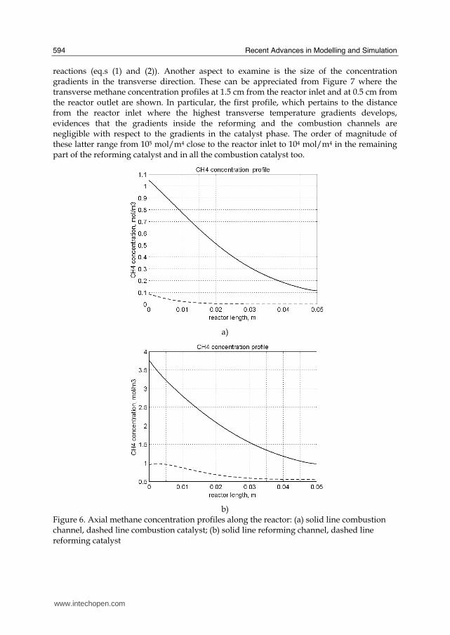
Recent Advances in Modelling and Simulation
594
reactions (eqs (1) and (2)) Another aspect to examine is the size of the concentration gradients in the transverse direction These can be appreciated from Figure 7 where the transverse methane concentration profiles at 15 cm from the reactor inlet and at 05 cm from the reactor outlet are shown In particular the first profile which pertains to the distance from the reactor inlet where the highest transverse temperature gradients develops evidences that the gradients inside the reforming and the combustion channels are negligible with respect to the gradients in the catalyst phase The order of magnitude of these latter range from 105 molm4 close to the reactor inlet to 104 molm4 in the remaining part of the reforming catalyst and in all the combustion catalyst too
a)
b)
Figure 6 Axial methane concentration profiles along the reactor (a) solid line combustion channel dashed line combustion catalyst (b) solid line reforming channel dashed line reforming catalyst
wwwintechopencom
Modeling of Surface-bed Reactor for Endothermic and Exothermic Reactions Coupling
595
Figure 7 Methane concentration transverse profiles at 15 cm from the reactor entrance (solid line) and at 10 cm from the reactor outlet (dashed line) From 0 to 1 reforming channel From 1 to 12 reforming catalyst From 12 to 17 metallic plate From 17 to 19 combustion catalyst From 19 to 24 combustion channel
43 Methane concentration in the combustion channel
A basic requirement of the system in the object which is thought to be used for energy feeding of portable electric devices should be the complete reliability with respect to possible uncontrolled rises in temperature or even to a possible explosion hazard In this view the coordination between exothermic and endothermic reaction rates appears fundamental However even in the case such a coordination occurs the possible progress of the combustion reaction in the homogeneous phase may represent an hazard In addition if the concentration of the reacting mixture entering the combustion channel is within the flammability limits and the temperature becomes high enough it could ignite before the reactor inlet Therefore for safety purposes the occurrence of the exothermic reaction here represented by the methane combustion in the homogeneous phase should be avoided A possible way to make the system of hydrogen generation intrinsically safe is to feed the combustion mixture at a methane concentration below the LEL (lower explosivity limit) Considering that at STP the LEL of methane in air is about 5 vol that the autoignition temperature for airmethane mixtures is around 900 K the extimated LEL of methane in air at such a temperature should be about 3 vol (Crowl amp Louvar (2002)) Therefore a safe operating concentration should be about 3 vol To this purpose in this work beside those carried out under the conditions considered in the reference case other simulations were effected for which for a given methane mass flow rate its concentration at the combustion channel inlet was kept below 3 vol In this way the system is intrinsically safe because the reacting mixture cannot ignite spontaneously In addition the simulation becomes more realistic the contribution to the methane combustion of the homogeneous phase being really absent as implicitly hypothesized in this work
wwwintechopencom
Recent Advances in Modelling and Simulation
596
Figure 8 Temperature distribution over the boundaries of the 3D reactor
The comparison of results of runs performed under these conditions with those effected under the conditions of the reference case are reported in the following when analyzing the influence of various parameters on the reactor performance These simulations are labeled in the paper as n-expl in contrast to the others that are recalled as expl
44 Comparison between 2D and 3D results
For given operating conditions some simulations were carried out in both 2D and 3D geometry In principle a plane 2D geometry represents a slice of the reactor where the z dimension is greatly prevalent with respect to the y dimension Actually the model reactor has not such characteristics the length in the z dimension being 10 mm that is only 5 times the reforming channel width This means that the boundary effects due to the presence of the boundary walls in the z direction may have a significant influence on the velocity temperature and species concentration profiles that certainly influence the overall reactor performance Figures 8 shows the temperature distribution over the boundaries of the 3D reactor obtained under operating conditions of the reference case From this Figure the effect of the boundaries along the z direction appears evident
wwwintechopencom
Modeling of Surface-bed Reactor for Endothermic and Exothermic Reactions Coupling
597
Figure 9 Temperature space profiles along the reactor calculated with the 2D model (for the legend see caption to Figure 2)
Figure 10 Temperature space profiles along the reactor calculated with the 3D model (for the legend see caption to Figure 2)
Figures 9 and 10 show the reactor temperature longitudinal profiles on the centerlines of the combustion and the reforming channels and on the centerline of the combustion and reforming catalysts in the case of 2D and 3D geometry models respectively Both were calculated under the same operating conditions ie same inlet mass flow rates and compositions of the reference case (expl) but inlet temperature of 900 K In the case of the
wwwintechopencom
Recent Advances in Modelling and Simulation
598
3D simulation (Figure 10) the temperature profiles are those lying over a xy plane intersecting the reactor in the middle of its height along z The two sets of profiles appear quite similar the temperatures in the combustion section (catalyst and channel) are always slightly higher than the corresponding ones in the reforming section However a closer inspection reveals some significant differences In the 2D case the temperature after an initial slow growth increases steadily from 900 K at the reactor inlet up to 965 K at the reactor outlet while in the other case it grows faster reaches 960 K at 60 of the reactor length and remains constant up to the outlet Another difference is represented by the larger transverse temperature gradients of the 3D case with respect to 2D In the 2D case they are comparable with those observed in Figure 2 for the reference case while in the 3D case they are almost double This is true for all combinations ie catalyst-catalyst catalyst-channel and channel-channel On the whole the 3D case shows a faster progress of the reactions with consequent need for faster heat transfer These differences in the thermal behaviour between 2D and 3D simulations persist when the comparison is extended to other operating conditions and in addition they reflect the better overall performance of the 3D reactor with respect to the 2D as can be seen by the following discussion The quantitative comparison between the 2D and 3D simulations was made with respect to the main results ie the methane conversion in both the combustion and the steam reforming channels as obtained from equation 5 Further beside the methane conversions other parameters are employed ie a) the gas hourly space velocities GHSV in the combustion and steam reforming sides of the reactor calculated as ratio between gas flow rates at the reactor inlet temperature and volume of catalyst b) the maximum temperature reached in the reactor c) the mean gas residence time trm in both the combustion and the reforming channel calculated as ratio between the gas flow rates at the reactor inlet temperature and the volume of the channel and d) the hydrogen yield φH2 evaluated as ratio between the amounts of methane reacted and hydrogen produced GHSV and trm were useful to allow the comparison of simulations carried out by changing the catalyst volume or the channel width as discussed later Results of simulations carried out with the 2D and 3D models under various operating conditions are reported in Table 5 Those referring to the operating conditions of the reference case are listed in the first two rows of such a Table The other operating conditions are i) same inlet temperature of the reference case but different methane concentration in the combustion channel (3rd and 4th rows of Table 5) and ii) different inlet temperatures for the two conditions above (5th-8th rows of Table 5) Focusing the comparison on the results of the simulations in 2D and 3D with the same operating conditions it appears that in general the methane conversions at the reactor outlet calculated with the 2D geometry in both the combustion and reforming channels are lower than the correspondent in 3D geometry but in one case (Xch4-sr 3rd and 4th rows of the Table) This finding reflects the differences in the thermal behaviour discussed above In any case such conversions differ by less than 10 but in the last two rows of the Table where the differences are larger It is worth noting however that even in this case the values of the conversions are congruent with the overall results of the simulation For instance the lower value of Xch4-co in the 2D with respect to the correspondent in 3D results in a lower value of Xch4-sr and in a lower maximum temperature reached in the reactor
wwwintechopencom
Modeling of Surface-bed Reactor for Endothermic and Exothermic Reactions Coupling
599
Geometry Tin K
Xch4-co Xch4-sr Tmax K Trm-co ms
Trm-sr ms
GHSVco h-1
GHSVsr h-1
φH2
2D expl 800 089 074 914 0057 0026 314840 702884 329
3D expl 800 096 077 914 0057 0026 314840 702884 333
2D n-expl 800 036 045 827 0020 0026 900588 702884 344
3D n-expl 800 040 041 828 0020 0026 900588 702884 356
2D expl 900 095 090 965 0051 0023 354194 790745 305
3D expl 900 099 093 960 0051 0023 354194 790745 300
2D n-expl 900 049 069 900 0018 0023 1013162 790745 322
3D n-expl 900 068 079 920 0018 0023 1013162 790745 318
Table 5 Comparison of 2D and 3D results obtained under the same operating conditions
For what concerns the hydrogen yield focusing again the comparison on the results of the simulations in 2D and 3D at the same operating conditions data show that φH2rsquos obtained with the 2D geometry model are lower than that in 3D model but in one case (7th and 8th row of Table 5) It is worth noting that φH2=3 would be the stoichiometric value if reaction (1) were the only occurring in the reforming catalyst so that the amount exceeding 3 is due to the contribution of reaction (2) Data in Table 5 also shows the influence on the reactor performance of temperature and inlet methane concentration in the combustion channel In the case of inlet temperature of 900 K and methane concentration within the explosivity limits (case referring to results in Figures 9 and 10) the methane conversion is practically 1 (3D model) for the combustion reaction and very high for the reforming reactions However under these conditions the hydrogen yield is the lowest In contrast when the highest hydrogen yield is reached the lowest methane conversion is achieved Similar considerations can be done for the other results in the Table so that a general trend can be drawn from such results The higher the maximum temperature reached in the reactor the higher the methane conversions and the lower the hydrogen yield
45 Influence of the channels width
The reactor thermal behaviour and performance was studied for different channels width Wc at constant inlet flow rates of the reaction mixtures Runs were also carried out by keeping constant the mean inlet velocities of reaction mixtures The variation range for the combustion channels width Wc-co was 1-15 mm and for the reforming channel width Wc-sr 2-3 mm All other parameters were kept at their reference case values Keeping constant the inlet mass flow rates and altering the channel width results in modifying the inlet velocities in the reactor and consequently the mean residence time (trm) of the gases in the channels but the GHSVrsquos do not change The results in terms of methane conversions in the combustion and reforming channels are reported in Table 6 for the reference cases (3rd and 4th row in Table) and for cases where the methane concentration in the combustion channels were below the LEL (1st and 2nd row) At constant mass flow rates the influence of the channel width or better of trm appears negligible under n-expl conditions with a slight
wwwintechopencom
Recent Advances in Modelling and Simulation
600
prevalence of the reactor with narrower channels and weak under expl conditions with in contrast better performance for the reactor with wider channels Therefore it is not possible to draw conclusions
Wc-sr mm
Tin K
Xch4 -
co Xch4-sr
Tmax K
trm-co ms
trm-sr ms
GHSVco h-1
GHSVsr h-1
2 n-expl 800 036 045 827 0020 0026 900588 702884
3 n-expl 800 034 044 819 0030 0038 900588 702884
2 expl 800 089 074 914 0057 0026 314840 702884
3 expl 800 092 081 940 0086 0038 314840 702884
Vcost- 3 n-expl 800 022 033 800 0020 0026 1350882 1054327
Table 6 Comparison between reactor performance as a function of channel width
Unlike the previous case where inlet flow rates were kept constant an increase in channel width keeping the mean gas velocity and the value of trm constants affects significantly the outlet conversions In this case the amount of reactants flowing through the reactor per unit catalyst volume and then GHSV increases (compare 1st and 5th rows in Table 5) Increasing channel widths from their reference case value (Wc-sr = 2 mm and Wc-co= 1) at constant gas inlet velocity leads to methane conversion reduction because a) the catalyst amount becomes insufficient for the amount of reactants fed in the reactor and b) the external mass transfer resistances play a stronger role The overall reaction heat fluxes remain the same as channel width increases leaving a similar amount of sensible heat to be used for heating up larger amounts of reactants This results in lower temperatures along the reactor
46 Influence of catalyst thickness
The influence of catalyst thickness c on the reactor behaviour was studied by keeping constant the reactants mass flow rates The reactor operation was simulated for three values of catalyst thickness ie 200 100 and 50 microm while keeping all the other parameters at their reference case values but for what concerns the inlet methane concentration in the combustion channel that was at non explosive level This with respect to the reference case corresponds to decreasing GHSV of factors 2 and 4 respectively Changes in the catalyst thickness influence considerably both thermal behaviour and outlet conversions As above the comparison is made through the methane conversions achieved in the two cases both in the steam reforming and in the combustion channels The results are reported in Table 7 It is evident that the loss of performance due to a decrease of 50 of c from 200 to 100 μm is almost negligible This is mainly due to the conservative parameters used for defining the catalyst layer characteristics (ie mean pore radius and tortuosity) that results in a very impervious path for diffusing gases However when c is further decreased methane conversion both in the combustion and in the reforming section significantly decrease The hydrogen yield does not change too much within the limits of the three cases analyzed
wwwintechopencom
Modeling of Surface-bed Reactor for Endothermic and Exothermic Reactions Coupling
601
δc μm
Tin K Xch4 -co Xch4-sr Tmax Ktrm-co ms
trm-sr ms
GHSVco h-1
GHSVsr h-1
φH2
200 n-expl 800 036 045 827 0020 0026 900588 702884 344
100 n-expl 800 035 045 827 0020 0026 1801176 1405768 344
50 n-expl 800 027 038 800 0020 0026 3602352 2811536 342
Table 7 Comparison between reactor performance as a function of catalyst thickness
5 Discussion
As seen in the previous section (4) there are several operating parameters that influence the performances of the system They are typical of reacting systems and can be summarized as GHSVrsquos tmrrsquos and inlet gas temperatures The particularity of the present case is the simultaneous occurrence of two coupled reactions one exothermic and the other endothermic in which the extent of the second depends on the extent (heat produced) of the first and the effectiveness of the heat transferred In addition the coupling of the two reactions does not exclude to have for each set of values of the mentioned parameters pertaining to one reaction several sets of parameters for the other reaction This makes the system quite complex and difficult to analyze However some general considerations can be drawn
Figure 11 Methane conversions in the combustion and reforming sides of the reactor as a function of GHSV for various operating conditions available in Table 6 and 7
The first is that as expected GHVS plays a key role in determining the reactor performances although this is supported by only a part of the data For instance data in Table 7 pertaining to simulations of the influence of such a parameter carried out by changing GHSV in the same way for both sections of the reacting system shows a clear effect of GHSV the reactor
0 1000000 2000000 3000000 4000000
GHSV h-1
02
04
06
08
1
XC
H4
-co a
nd
XC
H4
-sr -
data from Table 7 comb side
data from Table 7 refor side
data from Table 6 comb side
data from Table 6 refor side
wwwintechopencom
Recent Advances in Modelling and Simulation
602
performance decreases as GHSV increases on both sides of the reactor Such an influence does not appear strong the conversion change being about 20 against GHSV variations of a factor 4 (Figure 11) The influence of GHSV is more evident from data in Table 6 pertaining to simulations of the influence of tmr In fact also in this case a clear trend appears and the influence even though in the same direction of the previous case appears much stronger since with respect to a GHSV change of about 20 the methane conversion varies by a factor 4 (Figure 11) Such a strong influence is due to the combined effect of tmr especially on the combustion side of the reactor (cfr Table 6) Instead for data in Table 5 pertaining to simulations of the reliability of 2D and 3D models and the effect of gas inlet temperature it is not possible to highlight a clear influence The comparison between the results obtained with the 2D and 3D models under the same operating conditions have evidenced differences in the performance of the reactor not large but significant When we move from 2D to 3D models such differences result in an increase from 5 to 20 of both Xch4-co and Xch4-sr which reflects a different thermal behavior of the reacting system and influence also the hydrogen yield It is worth noting that the computation time required in the two cases is very different Specifically using an HP xw8400workstation equipped with 2 Xeon processors and 4 GB of RAM a 2D simulation takes on the average about 20 minutes with respect to 50-60 hours necessary in the 3D case It is impossible by now to establish which is the more correct or the more reliable In particular it should be assessed if 2D simulations are suitable for purpose of reactor design and experimental data interpretation The answer should come from the comparison of the results of such simulations with experimental data obtained with a real reactor geometrically comparable operated under conditions as much as similar to those fixed for the simulations This represents argument for coming work of the authors Further interesting aspects to be studied are the simulation of unsteady-state conditions and specifically of the system start-up and of the system response to small changes in the gas feeding flow rates and temperatures
6 Conclusions
Methane steam reforming coupled with methane catalytic combustion by means of indirect heat transfer in a surface-bed catalytic reactor was studied by 2D and 3D models The reactor consists of a central reforming channel and two lateral combustion channels A reference case for what concerns operating conditions and reactor geometry was chosen and its simulation was carried out Changes of reactor performance as consequence of operating parameters and reactor geometry variations were analyzed with respect to the reference case The simulation showed that suitable amount of fuel and adequate catalyst activity in the combustion channel can provide enough heat to simultaneously heat up the reaction mixture and drive the endothermic process The proximity between the heat source and the heat sink increases the efficiency of heat transfer resulting in transverse temperature gradients do not exceeding generally 07 K across the metallic wall and 20 K across the gas in the channel Decrease of transverse temperature differences and intraphase mass transfer resistances have the global effect of reducing the reactor dimension and the catalyst amount The influence of channels width and catalyst layer thickness on reactor behaviour was also studied At constant inlet flow rates changes of channel width in the range 1ndash2 mm do not introduce significant differences in the reactor performance Rather small differences in the
wwwintechopencom
Modeling of Surface-bed Reactor for Endothermic and Exothermic Reactions Coupling
603
catalyst axial temperature profiles and outlet methane conversions are observed In contrast altering the channel width at constant inlet velocities has strong influence Larger channel width results in lower conversion and smoother axial temperature profiles Intraphase resistances are present even for catalyst thickness of micrometers for both reforming and combustion processes Increasing GHSV that is the inlet flow ratecatalyst volume ratio leads to lower outlet conversions Due to different effect of catalyst layer thickness on reforming and combustion channels there are significant changes in the reactor temperature profile Results indicate that steam reforming of methane in a surface-bed reactor is feasible provided that mass flow rates channels width catalyst loadings and thickness are properly designed
7 Notation
cp specific heat J(mol K) c concentration molm3 Deff effective diffusion coefficient m2s D molecular diffusion coefficient m2s GHSV gas hourly space velocity h-1 k thermal conductivity W(m K) or reaction rate constant Ke equilibrium constant M molecular weight kgmol LEL lower explosivity limit vol
unit vector perpendicular to the flux surface
N molar flux at the boundary mol(m2 s) p partial pressure bar P total pressure bar q thermal flux at the boundary J(m2 s) r reaction rate various dimensions (see eqs 1rsquo 2rsquo and 3rsquo) Rp catalyst pore radius nm STP standard temperature and pressure (298 K and 101 103 Pa) t time s T temperature K ts transverse surface ux Velocity component on the x coordinate
velocity vector
v normal component of velocity at the channel ingress x axial coordinate m X conversion y transverse coordinate m Wc distance between the reactor plates m z vertical coordinate m Greek letters ΔH0r heat of reaction at reference state conditions KJmol c catalyst thickness μm catalyst porosity φ atomic diffusion volume or chemical reaction yield
wwwintechopencom
Recent Advances in Modelling and Simulation
604
θ stoichiometric coefficient ρ density kgm3 τ catalyst tortuosity
Subscripts and superscripts cat catalyst co combustion CH4 methane H2 hydrogen in inlet i chemical species j channel k reaction l phase rm mean residence s metal sheet sr steam reforming 0 channel ingress 1 reforming reaction 2 water gas shift reaction 3 combustion reaction
8 Acknowledgements
The authors gratefully acknowledge the financial support of MIUR under grant PRIN ndeg 2006094333004
9 References
Akers WW amp Camp DP (1955) Kinetics of the methanendashsteam reaction AIChE Journal Vol 1 471ndash475 ISSN0001-1541
Allen DW Gerhard ER amp Likins Jr MR (1975) Kinetics of the MethanendashSteam Reaction Ind Eng Chem Proc Des Dev Vol 14 No 3 256-259 ISSN0196-4305
Aparicio L (1997) Transient Isotopic Studies and Microkinetic Modeling of Methane Reforming over Nickel Catalysts Journal of Catal Vol 165 No 2 262-274 ISSN 0021-9517
Avci AK Trimm DL amp İlsen Oumlnsan Z (2001) Heterogeneous reactor modeling for simulation of catalytic oxidation and steam reforming of methane Chem Eng Sci Vol 56 No 2 641-649 ISSN0009-2509
Bridger GW (1980) The steam reforming of hydrocarbons Catalysis Vol 3 39-69 ISSN0140-0568
Cao C Wang Y amp Rozmiarek RT (2005) Heterogeneous reactor model for steam reforming of methane in a microchannel reactor with microstructured catalysts Catal Today Vol 110 No 1-2 92ndash97 ISSN 0920-5861
Craciun R Shereck B amp Gorte RJ (1998) Kinetic studies of methane steam reforming on ceria-supported Pd Catal Lett Vol 51 No 3ndash4 149-153 ISSN 1011-372x
wwwintechopencom
Modeling of Surface-bed Reactor for Endothermic and Exothermic Reactions Coupling
605
Crowl DA amp Louvar JF (2002) Chemical Process Safety fundamentals with applications 2nd ed Prentice Hall PTR Upper Saddle River NJ USA ISBN 0-13mdash018176-5
De Deken J C Devos E F amp Froment G F (1982) Steam reforming of natural gas Intrinsic kinetics diffusional influences and reactor design ACS Symposium Series 196 181ndash197 ISSN0097-6156
Ehrfeld W amp Hessel V Lowe H (2000) Microreactor Wiley-VCH Verlag GmbH D-69469 ISBN Weinheim Germany
Gosiewski K (2001) Simulations of non-stationary reactors for catalytic conversion of methane to synthesis gas Chem Eng Sci Vol 56 No 4 1501-1510 ISSN
Groppi G Belloli A Tronconi E Forzatti P (1995) A comparison of lumped and distributed models of monolith catalytic combustors Chem Eng Sci Vol 50 No 17 2705ndash2715 ISSN0009-2509
Holladay JD Wang Y amp Jones E (2004) Review of Developments in Portable Hydrogen Production Using Microreactor Technology Chem Rev Vol 104 No 10 4767-4790 ISSN 0009-2665
Hou K amp Hughes R (2001) The kinetics of methane steam reforming over a Ni-Al2O3 catalyst Chem Eng Journal Vol 82 No 1-3 311-328 ISSN 1385-8947
Jamal Y amp Wyszynski M L (1994) On-board generation of hydrogen-rich gaseous fuels a review Int J of Hydrogen Energy Vol 19 No 7 557-572 ISSN 0360-3199
Jensen KF (2001) Microreaction engineering is small better Chem Eng Sci Vol 56 No 2 293-303 ISSN0009-2509
Kolios G Gritsch A Glo1ckler B amp Sorescu G (2004) Novel Reactor Concepts for Thermally Efficient Methane Steam Reforming Modeling and Simulation Ind Eng Chem Res Vol 43 No 16 4796-4808 ISSN0888-5885
Kruger P Blakeley J amp Leaver J (2003) Potential in New Zealand for use of hydrogen as a transportation fuel Int J of Hydrogen Energy Vol 28 No 8 795ndash802 ISSN 0360-3199
Kvamsdal HM Svendsen HF Hertzberg T amp Olsvik O (1999) Dynamic simulation and optimization of a catalytic steam reformer Chem Eng Sci Vol 54 No 13-14 2697-2706 ISSN0009-2509
Lerer M Duic N Alves LM amp Carvalho MG (2006) H2 RES energy planning tool for increasing the penetration of renewable energy sources in island energy supply In New and Renewable Technologies for Sustanaible Development MG Carvalho and NH Afgan (Ed s) 15-30 World Scientific ISBN 10 981-270-505-8 Singapore
Lerou JJ amp Ng KM (1996) Chemical reaction engineering A multiscale approach to a multiobjective task Chem Eng Sci Vol 51 No 10 1595-1614 ISSN0009-2509
Lincoln SF (2006) Challenged Earth ch7 Imperial College Press ISBN 1-86094-526-0 London
Loffler D G Faz C F Sokolovskii V amp Iglesia E (2002) Catalytic separator plate reactor and method of catalytic reforming of fuel to Hydrogen PCT Int Appl WO 0228769 A2
Luna C amp Becerra AM (1997) Kinetics of methane steam reforming on a Ni on alumina-titania catalyst React Kinet Catal Lett Vol 61 No 2 369-374 ISSN 0133-1736
Marschner F Renner HJ amp Boll W (2005) Electronic Encyclopedia Release 2005 7th ed in Ullmannrsquos Encyclopedia of Industrial Chemistry M Bohnet et al (Eds) Vol a12 John Wiley amp Sons ISBN-13 978-3-527-30385-4
wwwintechopencom
Recent Advances in Modelling and Simulation
606
Moore R B amp Raman V (1998) Hydrogen infrastructure for fuel cell transportation Int J of Hydrogen Energy Vol 23 No 7 617-620 ISSN 0360-3199
Perry RH amp Green DW (1999) Perrys Chemical Engineers Handbook (7th Ed) McGraw-Hill ISBN 0-07-049841-5
Robbins F A Zhu H amp Jackson GS (2003) Transient modeling of combined catalytic combustionCH4 steam reformng Catal Today Vol 83 No 1-4 141ndash156 ISSN 0920-5861
Rostrup-Nielsen JR Christiansen LJ amp BakHansen JH (1988) Activity of steam reforming catalysts Role and assessment Appl Catal Vol 43 No 2 287-303 ISSN0166-9834
Rostrup-Nielsen JR (1995) Innovation and the catalytic process industry - the science and challenge Chem Eng Sci Vol 50 No 24 4061-4071 ISSN0009-2509
Rostrup-Nielsen JR Dybkjaer I amp Coulthard GRG (2001) Topical Conf Proc AIChE Spring National Meeting Houston TX April Paper No 1
Rostrup-Nielsen JR (2004) Fuels and Energy for the Future The Role of Catalysis Catal Rev - Science and Engineering Vol 46 No 3ndash4 247-270 ISSN0161-4940
Schubert K Brandner J Fichtner M Linder G Schyhulla U amp Wenka A (2001) Microstructure devices for applications in thermal and chemical process engineering Microscale Thermophys Eng Vol 5 No 1 17-39 ISSN1089-3954
Tronconi E amp Groppi G (2000) A study on the thermal behavior of structured plate-type catalysts with metallic supports for gassolid exothermic reactions Chem Eng Sci Vol 55 Issue 24 December 6021-6036 ISSN0009-2509
Wang Y Johnson BR Cao C Chin Y Rozmiarek RT Gao Y Tonkovich AL (2005) Engineered catalysts for microchannel reactor applications In Microreactor Technology and Process Intensification Y Wang J Holladay (Eds) 65-73 ACS Symposium Series Vol 914 ISBN-13 9780841239234
Xu J amp Froment GF (1989a) Methane steam reforming II Diffusional limitations and reactor simulation AIChE Journal Vol 35 No 1 97-103 ISSN0001-1541
Xu J amp Froment GF (1989b) Methane steam reforming methanation and water-gas shift I Intrinsic kinetics AIChE Journal Vol 35 No 1 88-96 ISSN0001-1541
Zanfir M amp Gavriilidis A (2003) Catalytic Combustion Assisted Methane Steam Reforming Chem Eng Sci Vol 58 No 17 3947ndash 3960 ISSN0009-2509
wwwintechopencom
Modelling and SimulationEdited by Giuseppe Petrone and Giuliano Cammarata
ISBN 978-3-902613-25-7Hard cover 688 pagesPublisher I-Tech Education and PublishingPublished online 01 June 2008Published in print edition June 2008
InTech EuropeUniversity Campus STeP Ri Slavka Krautzeka 83A 51000 Rijeka Croatia Phone +385 (51) 770 447 Fax +385 (51) 686 166wwwintechopencom
InTech ChinaUnit 405 Office Block Hotel Equatorial Shanghai No65 Yan An Road (West) Shanghai 200040 China
Phone +86-21-62489820 Fax +86-21-62489821
This book collects original and innovative research studies concerning modeling and simulation of physicalsystems in a very wide range of applications encompassing micro-electro-mechanical systems measurementinstrumentations catalytic reactors biomechanical applications biological and chemical sensorsmagnetosensitive materials silicon photonic devices electronic devices optical fibers electro-microfluidicsystems composite materials fuel cells indoor air-conditioning systems active magnetic levitation systemsand more Some of the most recent numerical techniques as well as some of the software among the mostaccurate and sophisticated in treating complex systems are applied in order to exhaustively contribute inknowledge advances
How to referenceIn order to correctly reference this scholarly work feel free to copy and paste the following
Salvatore Vaccaro and Paolo Ciambelli (2008) Modeling of Surface-bed Reactor for Endothermic andExothermic Reactions Coupling Modelling and Simulation Giuseppe Petrone and Giuliano Cammarata (Ed)ISBN 978-3-902613-25-7 InTech Available fromhttpwwwintechopencombooksmodelling_and_simulationmodeling_of_surface-bed_reactor_for_endothermic_and_exothermic_reactions_coupling
copy 2008 The Author(s) Licensee IntechOpen This chapter is distributedunder the terms of the Creative Commons Attribution-NonCommercial-ShareAlike-30 License which permits use distribution and reproduction fornon-commercial purposes provided the original is properly cited andderivative works building on this content are distributed under the samelicense
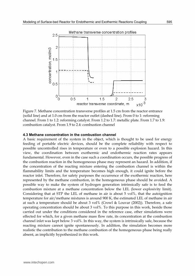
Modeling of Surface-bed Reactor for Endothermic and Exothermic Reactions Coupling
595
Figure 7 Methane concentration transverse profiles at 15 cm from the reactor entrance (solid line) and at 10 cm from the reactor outlet (dashed line) From 0 to 1 reforming channel From 1 to 12 reforming catalyst From 12 to 17 metallic plate From 17 to 19 combustion catalyst From 19 to 24 combustion channel
43 Methane concentration in the combustion channel
A basic requirement of the system in the object which is thought to be used for energy feeding of portable electric devices should be the complete reliability with respect to possible uncontrolled rises in temperature or even to a possible explosion hazard In this view the coordination between exothermic and endothermic reaction rates appears fundamental However even in the case such a coordination occurs the possible progress of the combustion reaction in the homogeneous phase may represent an hazard In addition if the concentration of the reacting mixture entering the combustion channel is within the flammability limits and the temperature becomes high enough it could ignite before the reactor inlet Therefore for safety purposes the occurrence of the exothermic reaction here represented by the methane combustion in the homogeneous phase should be avoided A possible way to make the system of hydrogen generation intrinsically safe is to feed the combustion mixture at a methane concentration below the LEL (lower explosivity limit) Considering that at STP the LEL of methane in air is about 5 vol that the autoignition temperature for airmethane mixtures is around 900 K the extimated LEL of methane in air at such a temperature should be about 3 vol (Crowl amp Louvar (2002)) Therefore a safe operating concentration should be about 3 vol To this purpose in this work beside those carried out under the conditions considered in the reference case other simulations were effected for which for a given methane mass flow rate its concentration at the combustion channel inlet was kept below 3 vol In this way the system is intrinsically safe because the reacting mixture cannot ignite spontaneously In addition the simulation becomes more realistic the contribution to the methane combustion of the homogeneous phase being really absent as implicitly hypothesized in this work
wwwintechopencom
Recent Advances in Modelling and Simulation
596
Figure 8 Temperature distribution over the boundaries of the 3D reactor
The comparison of results of runs performed under these conditions with those effected under the conditions of the reference case are reported in the following when analyzing the influence of various parameters on the reactor performance These simulations are labeled in the paper as n-expl in contrast to the others that are recalled as expl
44 Comparison between 2D and 3D results
For given operating conditions some simulations were carried out in both 2D and 3D geometry In principle a plane 2D geometry represents a slice of the reactor where the z dimension is greatly prevalent with respect to the y dimension Actually the model reactor has not such characteristics the length in the z dimension being 10 mm that is only 5 times the reforming channel width This means that the boundary effects due to the presence of the boundary walls in the z direction may have a significant influence on the velocity temperature and species concentration profiles that certainly influence the overall reactor performance Figures 8 shows the temperature distribution over the boundaries of the 3D reactor obtained under operating conditions of the reference case From this Figure the effect of the boundaries along the z direction appears evident
wwwintechopencom
Modeling of Surface-bed Reactor for Endothermic and Exothermic Reactions Coupling
597
Figure 9 Temperature space profiles along the reactor calculated with the 2D model (for the legend see caption to Figure 2)
Figure 10 Temperature space profiles along the reactor calculated with the 3D model (for the legend see caption to Figure 2)
Figures 9 and 10 show the reactor temperature longitudinal profiles on the centerlines of the combustion and the reforming channels and on the centerline of the combustion and reforming catalysts in the case of 2D and 3D geometry models respectively Both were calculated under the same operating conditions ie same inlet mass flow rates and compositions of the reference case (expl) but inlet temperature of 900 K In the case of the
wwwintechopencom
Recent Advances in Modelling and Simulation
598
3D simulation (Figure 10) the temperature profiles are those lying over a xy plane intersecting the reactor in the middle of its height along z The two sets of profiles appear quite similar the temperatures in the combustion section (catalyst and channel) are always slightly higher than the corresponding ones in the reforming section However a closer inspection reveals some significant differences In the 2D case the temperature after an initial slow growth increases steadily from 900 K at the reactor inlet up to 965 K at the reactor outlet while in the other case it grows faster reaches 960 K at 60 of the reactor length and remains constant up to the outlet Another difference is represented by the larger transverse temperature gradients of the 3D case with respect to 2D In the 2D case they are comparable with those observed in Figure 2 for the reference case while in the 3D case they are almost double This is true for all combinations ie catalyst-catalyst catalyst-channel and channel-channel On the whole the 3D case shows a faster progress of the reactions with consequent need for faster heat transfer These differences in the thermal behaviour between 2D and 3D simulations persist when the comparison is extended to other operating conditions and in addition they reflect the better overall performance of the 3D reactor with respect to the 2D as can be seen by the following discussion The quantitative comparison between the 2D and 3D simulations was made with respect to the main results ie the methane conversion in both the combustion and the steam reforming channels as obtained from equation 5 Further beside the methane conversions other parameters are employed ie a) the gas hourly space velocities GHSV in the combustion and steam reforming sides of the reactor calculated as ratio between gas flow rates at the reactor inlet temperature and volume of catalyst b) the maximum temperature reached in the reactor c) the mean gas residence time trm in both the combustion and the reforming channel calculated as ratio between the gas flow rates at the reactor inlet temperature and the volume of the channel and d) the hydrogen yield φH2 evaluated as ratio between the amounts of methane reacted and hydrogen produced GHSV and trm were useful to allow the comparison of simulations carried out by changing the catalyst volume or the channel width as discussed later Results of simulations carried out with the 2D and 3D models under various operating conditions are reported in Table 5 Those referring to the operating conditions of the reference case are listed in the first two rows of such a Table The other operating conditions are i) same inlet temperature of the reference case but different methane concentration in the combustion channel (3rd and 4th rows of Table 5) and ii) different inlet temperatures for the two conditions above (5th-8th rows of Table 5) Focusing the comparison on the results of the simulations in 2D and 3D with the same operating conditions it appears that in general the methane conversions at the reactor outlet calculated with the 2D geometry in both the combustion and reforming channels are lower than the correspondent in 3D geometry but in one case (Xch4-sr 3rd and 4th rows of the Table) This finding reflects the differences in the thermal behaviour discussed above In any case such conversions differ by less than 10 but in the last two rows of the Table where the differences are larger It is worth noting however that even in this case the values of the conversions are congruent with the overall results of the simulation For instance the lower value of Xch4-co in the 2D with respect to the correspondent in 3D results in a lower value of Xch4-sr and in a lower maximum temperature reached in the reactor
wwwintechopencom
Modeling of Surface-bed Reactor for Endothermic and Exothermic Reactions Coupling
599
Geometry Tin K
Xch4-co Xch4-sr Tmax K Trm-co ms
Trm-sr ms
GHSVco h-1
GHSVsr h-1
φH2
2D expl 800 089 074 914 0057 0026 314840 702884 329
3D expl 800 096 077 914 0057 0026 314840 702884 333
2D n-expl 800 036 045 827 0020 0026 900588 702884 344
3D n-expl 800 040 041 828 0020 0026 900588 702884 356
2D expl 900 095 090 965 0051 0023 354194 790745 305
3D expl 900 099 093 960 0051 0023 354194 790745 300
2D n-expl 900 049 069 900 0018 0023 1013162 790745 322
3D n-expl 900 068 079 920 0018 0023 1013162 790745 318
Table 5 Comparison of 2D and 3D results obtained under the same operating conditions
For what concerns the hydrogen yield focusing again the comparison on the results of the simulations in 2D and 3D at the same operating conditions data show that φH2rsquos obtained with the 2D geometry model are lower than that in 3D model but in one case (7th and 8th row of Table 5) It is worth noting that φH2=3 would be the stoichiometric value if reaction (1) were the only occurring in the reforming catalyst so that the amount exceeding 3 is due to the contribution of reaction (2) Data in Table 5 also shows the influence on the reactor performance of temperature and inlet methane concentration in the combustion channel In the case of inlet temperature of 900 K and methane concentration within the explosivity limits (case referring to results in Figures 9 and 10) the methane conversion is practically 1 (3D model) for the combustion reaction and very high for the reforming reactions However under these conditions the hydrogen yield is the lowest In contrast when the highest hydrogen yield is reached the lowest methane conversion is achieved Similar considerations can be done for the other results in the Table so that a general trend can be drawn from such results The higher the maximum temperature reached in the reactor the higher the methane conversions and the lower the hydrogen yield
45 Influence of the channels width
The reactor thermal behaviour and performance was studied for different channels width Wc at constant inlet flow rates of the reaction mixtures Runs were also carried out by keeping constant the mean inlet velocities of reaction mixtures The variation range for the combustion channels width Wc-co was 1-15 mm and for the reforming channel width Wc-sr 2-3 mm All other parameters were kept at their reference case values Keeping constant the inlet mass flow rates and altering the channel width results in modifying the inlet velocities in the reactor and consequently the mean residence time (trm) of the gases in the channels but the GHSVrsquos do not change The results in terms of methane conversions in the combustion and reforming channels are reported in Table 6 for the reference cases (3rd and 4th row in Table) and for cases where the methane concentration in the combustion channels were below the LEL (1st and 2nd row) At constant mass flow rates the influence of the channel width or better of trm appears negligible under n-expl conditions with a slight
wwwintechopencom
Recent Advances in Modelling and Simulation
600
prevalence of the reactor with narrower channels and weak under expl conditions with in contrast better performance for the reactor with wider channels Therefore it is not possible to draw conclusions
Wc-sr mm
Tin K
Xch4 -
co Xch4-sr
Tmax K
trm-co ms
trm-sr ms
GHSVco h-1
GHSVsr h-1
2 n-expl 800 036 045 827 0020 0026 900588 702884
3 n-expl 800 034 044 819 0030 0038 900588 702884
2 expl 800 089 074 914 0057 0026 314840 702884
3 expl 800 092 081 940 0086 0038 314840 702884
Vcost- 3 n-expl 800 022 033 800 0020 0026 1350882 1054327
Table 6 Comparison between reactor performance as a function of channel width
Unlike the previous case where inlet flow rates were kept constant an increase in channel width keeping the mean gas velocity and the value of trm constants affects significantly the outlet conversions In this case the amount of reactants flowing through the reactor per unit catalyst volume and then GHSV increases (compare 1st and 5th rows in Table 5) Increasing channel widths from their reference case value (Wc-sr = 2 mm and Wc-co= 1) at constant gas inlet velocity leads to methane conversion reduction because a) the catalyst amount becomes insufficient for the amount of reactants fed in the reactor and b) the external mass transfer resistances play a stronger role The overall reaction heat fluxes remain the same as channel width increases leaving a similar amount of sensible heat to be used for heating up larger amounts of reactants This results in lower temperatures along the reactor
46 Influence of catalyst thickness
The influence of catalyst thickness c on the reactor behaviour was studied by keeping constant the reactants mass flow rates The reactor operation was simulated for three values of catalyst thickness ie 200 100 and 50 microm while keeping all the other parameters at their reference case values but for what concerns the inlet methane concentration in the combustion channel that was at non explosive level This with respect to the reference case corresponds to decreasing GHSV of factors 2 and 4 respectively Changes in the catalyst thickness influence considerably both thermal behaviour and outlet conversions As above the comparison is made through the methane conversions achieved in the two cases both in the steam reforming and in the combustion channels The results are reported in Table 7 It is evident that the loss of performance due to a decrease of 50 of c from 200 to 100 μm is almost negligible This is mainly due to the conservative parameters used for defining the catalyst layer characteristics (ie mean pore radius and tortuosity) that results in a very impervious path for diffusing gases However when c is further decreased methane conversion both in the combustion and in the reforming section significantly decrease The hydrogen yield does not change too much within the limits of the three cases analyzed
wwwintechopencom
Modeling of Surface-bed Reactor for Endothermic and Exothermic Reactions Coupling
601
δc μm
Tin K Xch4 -co Xch4-sr Tmax Ktrm-co ms
trm-sr ms
GHSVco h-1
GHSVsr h-1
φH2
200 n-expl 800 036 045 827 0020 0026 900588 702884 344
100 n-expl 800 035 045 827 0020 0026 1801176 1405768 344
50 n-expl 800 027 038 800 0020 0026 3602352 2811536 342
Table 7 Comparison between reactor performance as a function of catalyst thickness
5 Discussion
As seen in the previous section (4) there are several operating parameters that influence the performances of the system They are typical of reacting systems and can be summarized as GHSVrsquos tmrrsquos and inlet gas temperatures The particularity of the present case is the simultaneous occurrence of two coupled reactions one exothermic and the other endothermic in which the extent of the second depends on the extent (heat produced) of the first and the effectiveness of the heat transferred In addition the coupling of the two reactions does not exclude to have for each set of values of the mentioned parameters pertaining to one reaction several sets of parameters for the other reaction This makes the system quite complex and difficult to analyze However some general considerations can be drawn
Figure 11 Methane conversions in the combustion and reforming sides of the reactor as a function of GHSV for various operating conditions available in Table 6 and 7
The first is that as expected GHVS plays a key role in determining the reactor performances although this is supported by only a part of the data For instance data in Table 7 pertaining to simulations of the influence of such a parameter carried out by changing GHSV in the same way for both sections of the reacting system shows a clear effect of GHSV the reactor
0 1000000 2000000 3000000 4000000
GHSV h-1
02
04
06
08
1
XC
H4
-co a
nd
XC
H4
-sr -
data from Table 7 comb side
data from Table 7 refor side
data from Table 6 comb side
data from Table 6 refor side
wwwintechopencom
Recent Advances in Modelling and Simulation
602
performance decreases as GHSV increases on both sides of the reactor Such an influence does not appear strong the conversion change being about 20 against GHSV variations of a factor 4 (Figure 11) The influence of GHSV is more evident from data in Table 6 pertaining to simulations of the influence of tmr In fact also in this case a clear trend appears and the influence even though in the same direction of the previous case appears much stronger since with respect to a GHSV change of about 20 the methane conversion varies by a factor 4 (Figure 11) Such a strong influence is due to the combined effect of tmr especially on the combustion side of the reactor (cfr Table 6) Instead for data in Table 5 pertaining to simulations of the reliability of 2D and 3D models and the effect of gas inlet temperature it is not possible to highlight a clear influence The comparison between the results obtained with the 2D and 3D models under the same operating conditions have evidenced differences in the performance of the reactor not large but significant When we move from 2D to 3D models such differences result in an increase from 5 to 20 of both Xch4-co and Xch4-sr which reflects a different thermal behavior of the reacting system and influence also the hydrogen yield It is worth noting that the computation time required in the two cases is very different Specifically using an HP xw8400workstation equipped with 2 Xeon processors and 4 GB of RAM a 2D simulation takes on the average about 20 minutes with respect to 50-60 hours necessary in the 3D case It is impossible by now to establish which is the more correct or the more reliable In particular it should be assessed if 2D simulations are suitable for purpose of reactor design and experimental data interpretation The answer should come from the comparison of the results of such simulations with experimental data obtained with a real reactor geometrically comparable operated under conditions as much as similar to those fixed for the simulations This represents argument for coming work of the authors Further interesting aspects to be studied are the simulation of unsteady-state conditions and specifically of the system start-up and of the system response to small changes in the gas feeding flow rates and temperatures
6 Conclusions
Methane steam reforming coupled with methane catalytic combustion by means of indirect heat transfer in a surface-bed catalytic reactor was studied by 2D and 3D models The reactor consists of a central reforming channel and two lateral combustion channels A reference case for what concerns operating conditions and reactor geometry was chosen and its simulation was carried out Changes of reactor performance as consequence of operating parameters and reactor geometry variations were analyzed with respect to the reference case The simulation showed that suitable amount of fuel and adequate catalyst activity in the combustion channel can provide enough heat to simultaneously heat up the reaction mixture and drive the endothermic process The proximity between the heat source and the heat sink increases the efficiency of heat transfer resulting in transverse temperature gradients do not exceeding generally 07 K across the metallic wall and 20 K across the gas in the channel Decrease of transverse temperature differences and intraphase mass transfer resistances have the global effect of reducing the reactor dimension and the catalyst amount The influence of channels width and catalyst layer thickness on reactor behaviour was also studied At constant inlet flow rates changes of channel width in the range 1ndash2 mm do not introduce significant differences in the reactor performance Rather small differences in the
wwwintechopencom
Modeling of Surface-bed Reactor for Endothermic and Exothermic Reactions Coupling
603
catalyst axial temperature profiles and outlet methane conversions are observed In contrast altering the channel width at constant inlet velocities has strong influence Larger channel width results in lower conversion and smoother axial temperature profiles Intraphase resistances are present even for catalyst thickness of micrometers for both reforming and combustion processes Increasing GHSV that is the inlet flow ratecatalyst volume ratio leads to lower outlet conversions Due to different effect of catalyst layer thickness on reforming and combustion channels there are significant changes in the reactor temperature profile Results indicate that steam reforming of methane in a surface-bed reactor is feasible provided that mass flow rates channels width catalyst loadings and thickness are properly designed
7 Notation
cp specific heat J(mol K) c concentration molm3 Deff effective diffusion coefficient m2s D molecular diffusion coefficient m2s GHSV gas hourly space velocity h-1 k thermal conductivity W(m K) or reaction rate constant Ke equilibrium constant M molecular weight kgmol LEL lower explosivity limit vol
unit vector perpendicular to the flux surface
N molar flux at the boundary mol(m2 s) p partial pressure bar P total pressure bar q thermal flux at the boundary J(m2 s) r reaction rate various dimensions (see eqs 1rsquo 2rsquo and 3rsquo) Rp catalyst pore radius nm STP standard temperature and pressure (298 K and 101 103 Pa) t time s T temperature K ts transverse surface ux Velocity component on the x coordinate
velocity vector
v normal component of velocity at the channel ingress x axial coordinate m X conversion y transverse coordinate m Wc distance between the reactor plates m z vertical coordinate m Greek letters ΔH0r heat of reaction at reference state conditions KJmol c catalyst thickness μm catalyst porosity φ atomic diffusion volume or chemical reaction yield
wwwintechopencom
Recent Advances in Modelling and Simulation
604
θ stoichiometric coefficient ρ density kgm3 τ catalyst tortuosity
Subscripts and superscripts cat catalyst co combustion CH4 methane H2 hydrogen in inlet i chemical species j channel k reaction l phase rm mean residence s metal sheet sr steam reforming 0 channel ingress 1 reforming reaction 2 water gas shift reaction 3 combustion reaction
8 Acknowledgements
The authors gratefully acknowledge the financial support of MIUR under grant PRIN ndeg 2006094333004
9 References
Akers WW amp Camp DP (1955) Kinetics of the methanendashsteam reaction AIChE Journal Vol 1 471ndash475 ISSN0001-1541
Allen DW Gerhard ER amp Likins Jr MR (1975) Kinetics of the MethanendashSteam Reaction Ind Eng Chem Proc Des Dev Vol 14 No 3 256-259 ISSN0196-4305
Aparicio L (1997) Transient Isotopic Studies and Microkinetic Modeling of Methane Reforming over Nickel Catalysts Journal of Catal Vol 165 No 2 262-274 ISSN 0021-9517
Avci AK Trimm DL amp İlsen Oumlnsan Z (2001) Heterogeneous reactor modeling for simulation of catalytic oxidation and steam reforming of methane Chem Eng Sci Vol 56 No 2 641-649 ISSN0009-2509
Bridger GW (1980) The steam reforming of hydrocarbons Catalysis Vol 3 39-69 ISSN0140-0568
Cao C Wang Y amp Rozmiarek RT (2005) Heterogeneous reactor model for steam reforming of methane in a microchannel reactor with microstructured catalysts Catal Today Vol 110 No 1-2 92ndash97 ISSN 0920-5861
Craciun R Shereck B amp Gorte RJ (1998) Kinetic studies of methane steam reforming on ceria-supported Pd Catal Lett Vol 51 No 3ndash4 149-153 ISSN 1011-372x
wwwintechopencom
Modeling of Surface-bed Reactor for Endothermic and Exothermic Reactions Coupling
605
Crowl DA amp Louvar JF (2002) Chemical Process Safety fundamentals with applications 2nd ed Prentice Hall PTR Upper Saddle River NJ USA ISBN 0-13mdash018176-5
De Deken J C Devos E F amp Froment G F (1982) Steam reforming of natural gas Intrinsic kinetics diffusional influences and reactor design ACS Symposium Series 196 181ndash197 ISSN0097-6156
Ehrfeld W amp Hessel V Lowe H (2000) Microreactor Wiley-VCH Verlag GmbH D-69469 ISBN Weinheim Germany
Gosiewski K (2001) Simulations of non-stationary reactors for catalytic conversion of methane to synthesis gas Chem Eng Sci Vol 56 No 4 1501-1510 ISSN
Groppi G Belloli A Tronconi E Forzatti P (1995) A comparison of lumped and distributed models of monolith catalytic combustors Chem Eng Sci Vol 50 No 17 2705ndash2715 ISSN0009-2509
Holladay JD Wang Y amp Jones E (2004) Review of Developments in Portable Hydrogen Production Using Microreactor Technology Chem Rev Vol 104 No 10 4767-4790 ISSN 0009-2665
Hou K amp Hughes R (2001) The kinetics of methane steam reforming over a Ni-Al2O3 catalyst Chem Eng Journal Vol 82 No 1-3 311-328 ISSN 1385-8947
Jamal Y amp Wyszynski M L (1994) On-board generation of hydrogen-rich gaseous fuels a review Int J of Hydrogen Energy Vol 19 No 7 557-572 ISSN 0360-3199
Jensen KF (2001) Microreaction engineering is small better Chem Eng Sci Vol 56 No 2 293-303 ISSN0009-2509
Kolios G Gritsch A Glo1ckler B amp Sorescu G (2004) Novel Reactor Concepts for Thermally Efficient Methane Steam Reforming Modeling and Simulation Ind Eng Chem Res Vol 43 No 16 4796-4808 ISSN0888-5885
Kruger P Blakeley J amp Leaver J (2003) Potential in New Zealand for use of hydrogen as a transportation fuel Int J of Hydrogen Energy Vol 28 No 8 795ndash802 ISSN 0360-3199
Kvamsdal HM Svendsen HF Hertzberg T amp Olsvik O (1999) Dynamic simulation and optimization of a catalytic steam reformer Chem Eng Sci Vol 54 No 13-14 2697-2706 ISSN0009-2509
Lerer M Duic N Alves LM amp Carvalho MG (2006) H2 RES energy planning tool for increasing the penetration of renewable energy sources in island energy supply In New and Renewable Technologies for Sustanaible Development MG Carvalho and NH Afgan (Ed s) 15-30 World Scientific ISBN 10 981-270-505-8 Singapore
Lerou JJ amp Ng KM (1996) Chemical reaction engineering A multiscale approach to a multiobjective task Chem Eng Sci Vol 51 No 10 1595-1614 ISSN0009-2509
Lincoln SF (2006) Challenged Earth ch7 Imperial College Press ISBN 1-86094-526-0 London
Loffler D G Faz C F Sokolovskii V amp Iglesia E (2002) Catalytic separator plate reactor and method of catalytic reforming of fuel to Hydrogen PCT Int Appl WO 0228769 A2
Luna C amp Becerra AM (1997) Kinetics of methane steam reforming on a Ni on alumina-titania catalyst React Kinet Catal Lett Vol 61 No 2 369-374 ISSN 0133-1736
Marschner F Renner HJ amp Boll W (2005) Electronic Encyclopedia Release 2005 7th ed in Ullmannrsquos Encyclopedia of Industrial Chemistry M Bohnet et al (Eds) Vol a12 John Wiley amp Sons ISBN-13 978-3-527-30385-4
wwwintechopencom
Recent Advances in Modelling and Simulation
606
Moore R B amp Raman V (1998) Hydrogen infrastructure for fuel cell transportation Int J of Hydrogen Energy Vol 23 No 7 617-620 ISSN 0360-3199
Perry RH amp Green DW (1999) Perrys Chemical Engineers Handbook (7th Ed) McGraw-Hill ISBN 0-07-049841-5
Robbins F A Zhu H amp Jackson GS (2003) Transient modeling of combined catalytic combustionCH4 steam reformng Catal Today Vol 83 No 1-4 141ndash156 ISSN 0920-5861
Rostrup-Nielsen JR Christiansen LJ amp BakHansen JH (1988) Activity of steam reforming catalysts Role and assessment Appl Catal Vol 43 No 2 287-303 ISSN0166-9834
Rostrup-Nielsen JR (1995) Innovation and the catalytic process industry - the science and challenge Chem Eng Sci Vol 50 No 24 4061-4071 ISSN0009-2509
Rostrup-Nielsen JR Dybkjaer I amp Coulthard GRG (2001) Topical Conf Proc AIChE Spring National Meeting Houston TX April Paper No 1
Rostrup-Nielsen JR (2004) Fuels and Energy for the Future The Role of Catalysis Catal Rev - Science and Engineering Vol 46 No 3ndash4 247-270 ISSN0161-4940
Schubert K Brandner J Fichtner M Linder G Schyhulla U amp Wenka A (2001) Microstructure devices for applications in thermal and chemical process engineering Microscale Thermophys Eng Vol 5 No 1 17-39 ISSN1089-3954
Tronconi E amp Groppi G (2000) A study on the thermal behavior of structured plate-type catalysts with metallic supports for gassolid exothermic reactions Chem Eng Sci Vol 55 Issue 24 December 6021-6036 ISSN0009-2509
Wang Y Johnson BR Cao C Chin Y Rozmiarek RT Gao Y Tonkovich AL (2005) Engineered catalysts for microchannel reactor applications In Microreactor Technology and Process Intensification Y Wang J Holladay (Eds) 65-73 ACS Symposium Series Vol 914 ISBN-13 9780841239234
Xu J amp Froment GF (1989a) Methane steam reforming II Diffusional limitations and reactor simulation AIChE Journal Vol 35 No 1 97-103 ISSN0001-1541
Xu J amp Froment GF (1989b) Methane steam reforming methanation and water-gas shift I Intrinsic kinetics AIChE Journal Vol 35 No 1 88-96 ISSN0001-1541
Zanfir M amp Gavriilidis A (2003) Catalytic Combustion Assisted Methane Steam Reforming Chem Eng Sci Vol 58 No 17 3947ndash 3960 ISSN0009-2509
wwwintechopencom
Modelling and SimulationEdited by Giuseppe Petrone and Giuliano Cammarata
ISBN 978-3-902613-25-7Hard cover 688 pagesPublisher I-Tech Education and PublishingPublished online 01 June 2008Published in print edition June 2008
InTech EuropeUniversity Campus STeP Ri Slavka Krautzeka 83A 51000 Rijeka Croatia Phone +385 (51) 770 447 Fax +385 (51) 686 166wwwintechopencom
InTech ChinaUnit 405 Office Block Hotel Equatorial Shanghai No65 Yan An Road (West) Shanghai 200040 China
Phone +86-21-62489820 Fax +86-21-62489821
This book collects original and innovative research studies concerning modeling and simulation of physicalsystems in a very wide range of applications encompassing micro-electro-mechanical systems measurementinstrumentations catalytic reactors biomechanical applications biological and chemical sensorsmagnetosensitive materials silicon photonic devices electronic devices optical fibers electro-microfluidicsystems composite materials fuel cells indoor air-conditioning systems active magnetic levitation systemsand more Some of the most recent numerical techniques as well as some of the software among the mostaccurate and sophisticated in treating complex systems are applied in order to exhaustively contribute inknowledge advances
How to referenceIn order to correctly reference this scholarly work feel free to copy and paste the following
Salvatore Vaccaro and Paolo Ciambelli (2008) Modeling of Surface-bed Reactor for Endothermic andExothermic Reactions Coupling Modelling and Simulation Giuseppe Petrone and Giuliano Cammarata (Ed)ISBN 978-3-902613-25-7 InTech Available fromhttpwwwintechopencombooksmodelling_and_simulationmodeling_of_surface-bed_reactor_for_endothermic_and_exothermic_reactions_coupling
copy 2008 The Author(s) Licensee IntechOpen This chapter is distributedunder the terms of the Creative Commons Attribution-NonCommercial-ShareAlike-30 License which permits use distribution and reproduction fornon-commercial purposes provided the original is properly cited andderivative works building on this content are distributed under the samelicense
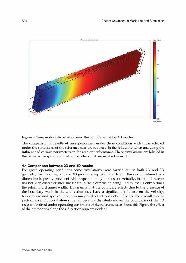
Recent Advances in Modelling and Simulation
596
Figure 8 Temperature distribution over the boundaries of the 3D reactor
The comparison of results of runs performed under these conditions with those effected under the conditions of the reference case are reported in the following when analyzing the influence of various parameters on the reactor performance These simulations are labeled in the paper as n-expl in contrast to the others that are recalled as expl
44 Comparison between 2D and 3D results
For given operating conditions some simulations were carried out in both 2D and 3D geometry In principle a plane 2D geometry represents a slice of the reactor where the z dimension is greatly prevalent with respect to the y dimension Actually the model reactor has not such characteristics the length in the z dimension being 10 mm that is only 5 times the reforming channel width This means that the boundary effects due to the presence of the boundary walls in the z direction may have a significant influence on the velocity temperature and species concentration profiles that certainly influence the overall reactor performance Figures 8 shows the temperature distribution over the boundaries of the 3D reactor obtained under operating conditions of the reference case From this Figure the effect of the boundaries along the z direction appears evident
wwwintechopencom
Modeling of Surface-bed Reactor for Endothermic and Exothermic Reactions Coupling
597
Figure 9 Temperature space profiles along the reactor calculated with the 2D model (for the legend see caption to Figure 2)
Figure 10 Temperature space profiles along the reactor calculated with the 3D model (for the legend see caption to Figure 2)
Figures 9 and 10 show the reactor temperature longitudinal profiles on the centerlines of the combustion and the reforming channels and on the centerline of the combustion and reforming catalysts in the case of 2D and 3D geometry models respectively Both were calculated under the same operating conditions ie same inlet mass flow rates and compositions of the reference case (expl) but inlet temperature of 900 K In the case of the
wwwintechopencom
Recent Advances in Modelling and Simulation
598
3D simulation (Figure 10) the temperature profiles are those lying over a xy plane intersecting the reactor in the middle of its height along z The two sets of profiles appear quite similar the temperatures in the combustion section (catalyst and channel) are always slightly higher than the corresponding ones in the reforming section However a closer inspection reveals some significant differences In the 2D case the temperature after an initial slow growth increases steadily from 900 K at the reactor inlet up to 965 K at the reactor outlet while in the other case it grows faster reaches 960 K at 60 of the reactor length and remains constant up to the outlet Another difference is represented by the larger transverse temperature gradients of the 3D case with respect to 2D In the 2D case they are comparable with those observed in Figure 2 for the reference case while in the 3D case they are almost double This is true for all combinations ie catalyst-catalyst catalyst-channel and channel-channel On the whole the 3D case shows a faster progress of the reactions with consequent need for faster heat transfer These differences in the thermal behaviour between 2D and 3D simulations persist when the comparison is extended to other operating conditions and in addition they reflect the better overall performance of the 3D reactor with respect to the 2D as can be seen by the following discussion The quantitative comparison between the 2D and 3D simulations was made with respect to the main results ie the methane conversion in both the combustion and the steam reforming channels as obtained from equation 5 Further beside the methane conversions other parameters are employed ie a) the gas hourly space velocities GHSV in the combustion and steam reforming sides of the reactor calculated as ratio between gas flow rates at the reactor inlet temperature and volume of catalyst b) the maximum temperature reached in the reactor c) the mean gas residence time trm in both the combustion and the reforming channel calculated as ratio between the gas flow rates at the reactor inlet temperature and the volume of the channel and d) the hydrogen yield φH2 evaluated as ratio between the amounts of methane reacted and hydrogen produced GHSV and trm were useful to allow the comparison of simulations carried out by changing the catalyst volume or the channel width as discussed later Results of simulations carried out with the 2D and 3D models under various operating conditions are reported in Table 5 Those referring to the operating conditions of the reference case are listed in the first two rows of such a Table The other operating conditions are i) same inlet temperature of the reference case but different methane concentration in the combustion channel (3rd and 4th rows of Table 5) and ii) different inlet temperatures for the two conditions above (5th-8th rows of Table 5) Focusing the comparison on the results of the simulations in 2D and 3D with the same operating conditions it appears that in general the methane conversions at the reactor outlet calculated with the 2D geometry in both the combustion and reforming channels are lower than the correspondent in 3D geometry but in one case (Xch4-sr 3rd and 4th rows of the Table) This finding reflects the differences in the thermal behaviour discussed above In any case such conversions differ by less than 10 but in the last two rows of the Table where the differences are larger It is worth noting however that even in this case the values of the conversions are congruent with the overall results of the simulation For instance the lower value of Xch4-co in the 2D with respect to the correspondent in 3D results in a lower value of Xch4-sr and in a lower maximum temperature reached in the reactor
wwwintechopencom
Modeling of Surface-bed Reactor for Endothermic and Exothermic Reactions Coupling
599
Geometry Tin K
Xch4-co Xch4-sr Tmax K Trm-co ms
Trm-sr ms
GHSVco h-1
GHSVsr h-1
φH2
2D expl 800 089 074 914 0057 0026 314840 702884 329
3D expl 800 096 077 914 0057 0026 314840 702884 333
2D n-expl 800 036 045 827 0020 0026 900588 702884 344
3D n-expl 800 040 041 828 0020 0026 900588 702884 356
2D expl 900 095 090 965 0051 0023 354194 790745 305
3D expl 900 099 093 960 0051 0023 354194 790745 300
2D n-expl 900 049 069 900 0018 0023 1013162 790745 322
3D n-expl 900 068 079 920 0018 0023 1013162 790745 318
Table 5 Comparison of 2D and 3D results obtained under the same operating conditions
For what concerns the hydrogen yield focusing again the comparison on the results of the simulations in 2D and 3D at the same operating conditions data show that φH2rsquos obtained with the 2D geometry model are lower than that in 3D model but in one case (7th and 8th row of Table 5) It is worth noting that φH2=3 would be the stoichiometric value if reaction (1) were the only occurring in the reforming catalyst so that the amount exceeding 3 is due to the contribution of reaction (2) Data in Table 5 also shows the influence on the reactor performance of temperature and inlet methane concentration in the combustion channel In the case of inlet temperature of 900 K and methane concentration within the explosivity limits (case referring to results in Figures 9 and 10) the methane conversion is practically 1 (3D model) for the combustion reaction and very high for the reforming reactions However under these conditions the hydrogen yield is the lowest In contrast when the highest hydrogen yield is reached the lowest methane conversion is achieved Similar considerations can be done for the other results in the Table so that a general trend can be drawn from such results The higher the maximum temperature reached in the reactor the higher the methane conversions and the lower the hydrogen yield
45 Influence of the channels width
The reactor thermal behaviour and performance was studied for different channels width Wc at constant inlet flow rates of the reaction mixtures Runs were also carried out by keeping constant the mean inlet velocities of reaction mixtures The variation range for the combustion channels width Wc-co was 1-15 mm and for the reforming channel width Wc-sr 2-3 mm All other parameters were kept at their reference case values Keeping constant the inlet mass flow rates and altering the channel width results in modifying the inlet velocities in the reactor and consequently the mean residence time (trm) of the gases in the channels but the GHSVrsquos do not change The results in terms of methane conversions in the combustion and reforming channels are reported in Table 6 for the reference cases (3rd and 4th row in Table) and for cases where the methane concentration in the combustion channels were below the LEL (1st and 2nd row) At constant mass flow rates the influence of the channel width or better of trm appears negligible under n-expl conditions with a slight
wwwintechopencom
Recent Advances in Modelling and Simulation
600
prevalence of the reactor with narrower channels and weak under expl conditions with in contrast better performance for the reactor with wider channels Therefore it is not possible to draw conclusions
Wc-sr mm
Tin K
Xch4 -
co Xch4-sr
Tmax K
trm-co ms
trm-sr ms
GHSVco h-1
GHSVsr h-1
2 n-expl 800 036 045 827 0020 0026 900588 702884
3 n-expl 800 034 044 819 0030 0038 900588 702884
2 expl 800 089 074 914 0057 0026 314840 702884
3 expl 800 092 081 940 0086 0038 314840 702884
Vcost- 3 n-expl 800 022 033 800 0020 0026 1350882 1054327
Table 6 Comparison between reactor performance as a function of channel width
Unlike the previous case where inlet flow rates were kept constant an increase in channel width keeping the mean gas velocity and the value of trm constants affects significantly the outlet conversions In this case the amount of reactants flowing through the reactor per unit catalyst volume and then GHSV increases (compare 1st and 5th rows in Table 5) Increasing channel widths from their reference case value (Wc-sr = 2 mm and Wc-co= 1) at constant gas inlet velocity leads to methane conversion reduction because a) the catalyst amount becomes insufficient for the amount of reactants fed in the reactor and b) the external mass transfer resistances play a stronger role The overall reaction heat fluxes remain the same as channel width increases leaving a similar amount of sensible heat to be used for heating up larger amounts of reactants This results in lower temperatures along the reactor
46 Influence of catalyst thickness
The influence of catalyst thickness c on the reactor behaviour was studied by keeping constant the reactants mass flow rates The reactor operation was simulated for three values of catalyst thickness ie 200 100 and 50 microm while keeping all the other parameters at their reference case values but for what concerns the inlet methane concentration in the combustion channel that was at non explosive level This with respect to the reference case corresponds to decreasing GHSV of factors 2 and 4 respectively Changes in the catalyst thickness influence considerably both thermal behaviour and outlet conversions As above the comparison is made through the methane conversions achieved in the two cases both in the steam reforming and in the combustion channels The results are reported in Table 7 It is evident that the loss of performance due to a decrease of 50 of c from 200 to 100 μm is almost negligible This is mainly due to the conservative parameters used for defining the catalyst layer characteristics (ie mean pore radius and tortuosity) that results in a very impervious path for diffusing gases However when c is further decreased methane conversion both in the combustion and in the reforming section significantly decrease The hydrogen yield does not change too much within the limits of the three cases analyzed
wwwintechopencom
Modeling of Surface-bed Reactor for Endothermic and Exothermic Reactions Coupling
601
δc μm
Tin K Xch4 -co Xch4-sr Tmax Ktrm-co ms
trm-sr ms
GHSVco h-1
GHSVsr h-1
φH2
200 n-expl 800 036 045 827 0020 0026 900588 702884 344
100 n-expl 800 035 045 827 0020 0026 1801176 1405768 344
50 n-expl 800 027 038 800 0020 0026 3602352 2811536 342
Table 7 Comparison between reactor performance as a function of catalyst thickness
5 Discussion
As seen in the previous section (4) there are several operating parameters that influence the performances of the system They are typical of reacting systems and can be summarized as GHSVrsquos tmrrsquos and inlet gas temperatures The particularity of the present case is the simultaneous occurrence of two coupled reactions one exothermic and the other endothermic in which the extent of the second depends on the extent (heat produced) of the first and the effectiveness of the heat transferred In addition the coupling of the two reactions does not exclude to have for each set of values of the mentioned parameters pertaining to one reaction several sets of parameters for the other reaction This makes the system quite complex and difficult to analyze However some general considerations can be drawn
Figure 11 Methane conversions in the combustion and reforming sides of the reactor as a function of GHSV for various operating conditions available in Table 6 and 7
The first is that as expected GHVS plays a key role in determining the reactor performances although this is supported by only a part of the data For instance data in Table 7 pertaining to simulations of the influence of such a parameter carried out by changing GHSV in the same way for both sections of the reacting system shows a clear effect of GHSV the reactor
0 1000000 2000000 3000000 4000000
GHSV h-1
02
04
06
08
1
XC
H4
-co a
nd
XC
H4
-sr -
data from Table 7 comb side
data from Table 7 refor side
data from Table 6 comb side
data from Table 6 refor side
wwwintechopencom
Recent Advances in Modelling and Simulation
602
performance decreases as GHSV increases on both sides of the reactor Such an influence does not appear strong the conversion change being about 20 against GHSV variations of a factor 4 (Figure 11) The influence of GHSV is more evident from data in Table 6 pertaining to simulations of the influence of tmr In fact also in this case a clear trend appears and the influence even though in the same direction of the previous case appears much stronger since with respect to a GHSV change of about 20 the methane conversion varies by a factor 4 (Figure 11) Such a strong influence is due to the combined effect of tmr especially on the combustion side of the reactor (cfr Table 6) Instead for data in Table 5 pertaining to simulations of the reliability of 2D and 3D models and the effect of gas inlet temperature it is not possible to highlight a clear influence The comparison between the results obtained with the 2D and 3D models under the same operating conditions have evidenced differences in the performance of the reactor not large but significant When we move from 2D to 3D models such differences result in an increase from 5 to 20 of both Xch4-co and Xch4-sr which reflects a different thermal behavior of the reacting system and influence also the hydrogen yield It is worth noting that the computation time required in the two cases is very different Specifically using an HP xw8400workstation equipped with 2 Xeon processors and 4 GB of RAM a 2D simulation takes on the average about 20 minutes with respect to 50-60 hours necessary in the 3D case It is impossible by now to establish which is the more correct or the more reliable In particular it should be assessed if 2D simulations are suitable for purpose of reactor design and experimental data interpretation The answer should come from the comparison of the results of such simulations with experimental data obtained with a real reactor geometrically comparable operated under conditions as much as similar to those fixed for the simulations This represents argument for coming work of the authors Further interesting aspects to be studied are the simulation of unsteady-state conditions and specifically of the system start-up and of the system response to small changes in the gas feeding flow rates and temperatures
6 Conclusions
Methane steam reforming coupled with methane catalytic combustion by means of indirect heat transfer in a surface-bed catalytic reactor was studied by 2D and 3D models The reactor consists of a central reforming channel and two lateral combustion channels A reference case for what concerns operating conditions and reactor geometry was chosen and its simulation was carried out Changes of reactor performance as consequence of operating parameters and reactor geometry variations were analyzed with respect to the reference case The simulation showed that suitable amount of fuel and adequate catalyst activity in the combustion channel can provide enough heat to simultaneously heat up the reaction mixture and drive the endothermic process The proximity between the heat source and the heat sink increases the efficiency of heat transfer resulting in transverse temperature gradients do not exceeding generally 07 K across the metallic wall and 20 K across the gas in the channel Decrease of transverse temperature differences and intraphase mass transfer resistances have the global effect of reducing the reactor dimension and the catalyst amount The influence of channels width and catalyst layer thickness on reactor behaviour was also studied At constant inlet flow rates changes of channel width in the range 1ndash2 mm do not introduce significant differences in the reactor performance Rather small differences in the
wwwintechopencom
Modeling of Surface-bed Reactor for Endothermic and Exothermic Reactions Coupling
603
catalyst axial temperature profiles and outlet methane conversions are observed In contrast altering the channel width at constant inlet velocities has strong influence Larger channel width results in lower conversion and smoother axial temperature profiles Intraphase resistances are present even for catalyst thickness of micrometers for both reforming and combustion processes Increasing GHSV that is the inlet flow ratecatalyst volume ratio leads to lower outlet conversions Due to different effect of catalyst layer thickness on reforming and combustion channels there are significant changes in the reactor temperature profile Results indicate that steam reforming of methane in a surface-bed reactor is feasible provided that mass flow rates channels width catalyst loadings and thickness are properly designed
7 Notation
cp specific heat J(mol K) c concentration molm3 Deff effective diffusion coefficient m2s D molecular diffusion coefficient m2s GHSV gas hourly space velocity h-1 k thermal conductivity W(m K) or reaction rate constant Ke equilibrium constant M molecular weight kgmol LEL lower explosivity limit vol
unit vector perpendicular to the flux surface
N molar flux at the boundary mol(m2 s) p partial pressure bar P total pressure bar q thermal flux at the boundary J(m2 s) r reaction rate various dimensions (see eqs 1rsquo 2rsquo and 3rsquo) Rp catalyst pore radius nm STP standard temperature and pressure (298 K and 101 103 Pa) t time s T temperature K ts transverse surface ux Velocity component on the x coordinate
velocity vector
v normal component of velocity at the channel ingress x axial coordinate m X conversion y transverse coordinate m Wc distance between the reactor plates m z vertical coordinate m Greek letters ΔH0r heat of reaction at reference state conditions KJmol c catalyst thickness μm catalyst porosity φ atomic diffusion volume or chemical reaction yield
wwwintechopencom
Recent Advances in Modelling and Simulation
604
θ stoichiometric coefficient ρ density kgm3 τ catalyst tortuosity
Subscripts and superscripts cat catalyst co combustion CH4 methane H2 hydrogen in inlet i chemical species j channel k reaction l phase rm mean residence s metal sheet sr steam reforming 0 channel ingress 1 reforming reaction 2 water gas shift reaction 3 combustion reaction
8 Acknowledgements
The authors gratefully acknowledge the financial support of MIUR under grant PRIN ndeg 2006094333004
9 References
Akers WW amp Camp DP (1955) Kinetics of the methanendashsteam reaction AIChE Journal Vol 1 471ndash475 ISSN0001-1541
Allen DW Gerhard ER amp Likins Jr MR (1975) Kinetics of the MethanendashSteam Reaction Ind Eng Chem Proc Des Dev Vol 14 No 3 256-259 ISSN0196-4305
Aparicio L (1997) Transient Isotopic Studies and Microkinetic Modeling of Methane Reforming over Nickel Catalysts Journal of Catal Vol 165 No 2 262-274 ISSN 0021-9517
Avci AK Trimm DL amp İlsen Oumlnsan Z (2001) Heterogeneous reactor modeling for simulation of catalytic oxidation and steam reforming of methane Chem Eng Sci Vol 56 No 2 641-649 ISSN0009-2509
Bridger GW (1980) The steam reforming of hydrocarbons Catalysis Vol 3 39-69 ISSN0140-0568
Cao C Wang Y amp Rozmiarek RT (2005) Heterogeneous reactor model for steam reforming of methane in a microchannel reactor with microstructured catalysts Catal Today Vol 110 No 1-2 92ndash97 ISSN 0920-5861
Craciun R Shereck B amp Gorte RJ (1998) Kinetic studies of methane steam reforming on ceria-supported Pd Catal Lett Vol 51 No 3ndash4 149-153 ISSN 1011-372x
wwwintechopencom
Modeling of Surface-bed Reactor for Endothermic and Exothermic Reactions Coupling
605
Crowl DA amp Louvar JF (2002) Chemical Process Safety fundamentals with applications 2nd ed Prentice Hall PTR Upper Saddle River NJ USA ISBN 0-13mdash018176-5
De Deken J C Devos E F amp Froment G F (1982) Steam reforming of natural gas Intrinsic kinetics diffusional influences and reactor design ACS Symposium Series 196 181ndash197 ISSN0097-6156
Ehrfeld W amp Hessel V Lowe H (2000) Microreactor Wiley-VCH Verlag GmbH D-69469 ISBN Weinheim Germany
Gosiewski K (2001) Simulations of non-stationary reactors for catalytic conversion of methane to synthesis gas Chem Eng Sci Vol 56 No 4 1501-1510 ISSN
Groppi G Belloli A Tronconi E Forzatti P (1995) A comparison of lumped and distributed models of monolith catalytic combustors Chem Eng Sci Vol 50 No 17 2705ndash2715 ISSN0009-2509
Holladay JD Wang Y amp Jones E (2004) Review of Developments in Portable Hydrogen Production Using Microreactor Technology Chem Rev Vol 104 No 10 4767-4790 ISSN 0009-2665
Hou K amp Hughes R (2001) The kinetics of methane steam reforming over a Ni-Al2O3 catalyst Chem Eng Journal Vol 82 No 1-3 311-328 ISSN 1385-8947
Jamal Y amp Wyszynski M L (1994) On-board generation of hydrogen-rich gaseous fuels a review Int J of Hydrogen Energy Vol 19 No 7 557-572 ISSN 0360-3199
Jensen KF (2001) Microreaction engineering is small better Chem Eng Sci Vol 56 No 2 293-303 ISSN0009-2509
Kolios G Gritsch A Glo1ckler B amp Sorescu G (2004) Novel Reactor Concepts for Thermally Efficient Methane Steam Reforming Modeling and Simulation Ind Eng Chem Res Vol 43 No 16 4796-4808 ISSN0888-5885
Kruger P Blakeley J amp Leaver J (2003) Potential in New Zealand for use of hydrogen as a transportation fuel Int J of Hydrogen Energy Vol 28 No 8 795ndash802 ISSN 0360-3199
Kvamsdal HM Svendsen HF Hertzberg T amp Olsvik O (1999) Dynamic simulation and optimization of a catalytic steam reformer Chem Eng Sci Vol 54 No 13-14 2697-2706 ISSN0009-2509
Lerer M Duic N Alves LM amp Carvalho MG (2006) H2 RES energy planning tool for increasing the penetration of renewable energy sources in island energy supply In New and Renewable Technologies for Sustanaible Development MG Carvalho and NH Afgan (Ed s) 15-30 World Scientific ISBN 10 981-270-505-8 Singapore
Lerou JJ amp Ng KM (1996) Chemical reaction engineering A multiscale approach to a multiobjective task Chem Eng Sci Vol 51 No 10 1595-1614 ISSN0009-2509
Lincoln SF (2006) Challenged Earth ch7 Imperial College Press ISBN 1-86094-526-0 London
Loffler D G Faz C F Sokolovskii V amp Iglesia E (2002) Catalytic separator plate reactor and method of catalytic reforming of fuel to Hydrogen PCT Int Appl WO 0228769 A2
Luna C amp Becerra AM (1997) Kinetics of methane steam reforming on a Ni on alumina-titania catalyst React Kinet Catal Lett Vol 61 No 2 369-374 ISSN 0133-1736
Marschner F Renner HJ amp Boll W (2005) Electronic Encyclopedia Release 2005 7th ed in Ullmannrsquos Encyclopedia of Industrial Chemistry M Bohnet et al (Eds) Vol a12 John Wiley amp Sons ISBN-13 978-3-527-30385-4
wwwintechopencom
Recent Advances in Modelling and Simulation
606
Moore R B amp Raman V (1998) Hydrogen infrastructure for fuel cell transportation Int J of Hydrogen Energy Vol 23 No 7 617-620 ISSN 0360-3199
Perry RH amp Green DW (1999) Perrys Chemical Engineers Handbook (7th Ed) McGraw-Hill ISBN 0-07-049841-5
Robbins F A Zhu H amp Jackson GS (2003) Transient modeling of combined catalytic combustionCH4 steam reformng Catal Today Vol 83 No 1-4 141ndash156 ISSN 0920-5861
Rostrup-Nielsen JR Christiansen LJ amp BakHansen JH (1988) Activity of steam reforming catalysts Role and assessment Appl Catal Vol 43 No 2 287-303 ISSN0166-9834
Rostrup-Nielsen JR (1995) Innovation and the catalytic process industry - the science and challenge Chem Eng Sci Vol 50 No 24 4061-4071 ISSN0009-2509
Rostrup-Nielsen JR Dybkjaer I amp Coulthard GRG (2001) Topical Conf Proc AIChE Spring National Meeting Houston TX April Paper No 1
Rostrup-Nielsen JR (2004) Fuels and Energy for the Future The Role of Catalysis Catal Rev - Science and Engineering Vol 46 No 3ndash4 247-270 ISSN0161-4940
Schubert K Brandner J Fichtner M Linder G Schyhulla U amp Wenka A (2001) Microstructure devices for applications in thermal and chemical process engineering Microscale Thermophys Eng Vol 5 No 1 17-39 ISSN1089-3954
Tronconi E amp Groppi G (2000) A study on the thermal behavior of structured plate-type catalysts with metallic supports for gassolid exothermic reactions Chem Eng Sci Vol 55 Issue 24 December 6021-6036 ISSN0009-2509
Wang Y Johnson BR Cao C Chin Y Rozmiarek RT Gao Y Tonkovich AL (2005) Engineered catalysts for microchannel reactor applications In Microreactor Technology and Process Intensification Y Wang J Holladay (Eds) 65-73 ACS Symposium Series Vol 914 ISBN-13 9780841239234
Xu J amp Froment GF (1989a) Methane steam reforming II Diffusional limitations and reactor simulation AIChE Journal Vol 35 No 1 97-103 ISSN0001-1541
Xu J amp Froment GF (1989b) Methane steam reforming methanation and water-gas shift I Intrinsic kinetics AIChE Journal Vol 35 No 1 88-96 ISSN0001-1541
Zanfir M amp Gavriilidis A (2003) Catalytic Combustion Assisted Methane Steam Reforming Chem Eng Sci Vol 58 No 17 3947ndash 3960 ISSN0009-2509
wwwintechopencom
Modelling and SimulationEdited by Giuseppe Petrone and Giuliano Cammarata
ISBN 978-3-902613-25-7Hard cover 688 pagesPublisher I-Tech Education and PublishingPublished online 01 June 2008Published in print edition June 2008
InTech EuropeUniversity Campus STeP Ri Slavka Krautzeka 83A 51000 Rijeka Croatia Phone +385 (51) 770 447 Fax +385 (51) 686 166wwwintechopencom
InTech ChinaUnit 405 Office Block Hotel Equatorial Shanghai No65 Yan An Road (West) Shanghai 200040 China
Phone +86-21-62489820 Fax +86-21-62489821
This book collects original and innovative research studies concerning modeling and simulation of physicalsystems in a very wide range of applications encompassing micro-electro-mechanical systems measurementinstrumentations catalytic reactors biomechanical applications biological and chemical sensorsmagnetosensitive materials silicon photonic devices electronic devices optical fibers electro-microfluidicsystems composite materials fuel cells indoor air-conditioning systems active magnetic levitation systemsand more Some of the most recent numerical techniques as well as some of the software among the mostaccurate and sophisticated in treating complex systems are applied in order to exhaustively contribute inknowledge advances
How to referenceIn order to correctly reference this scholarly work feel free to copy and paste the following
Salvatore Vaccaro and Paolo Ciambelli (2008) Modeling of Surface-bed Reactor for Endothermic andExothermic Reactions Coupling Modelling and Simulation Giuseppe Petrone and Giuliano Cammarata (Ed)ISBN 978-3-902613-25-7 InTech Available fromhttpwwwintechopencombooksmodelling_and_simulationmodeling_of_surface-bed_reactor_for_endothermic_and_exothermic_reactions_coupling
copy 2008 The Author(s) Licensee IntechOpen This chapter is distributedunder the terms of the Creative Commons Attribution-NonCommercial-ShareAlike-30 License which permits use distribution and reproduction fornon-commercial purposes provided the original is properly cited andderivative works building on this content are distributed under the samelicense
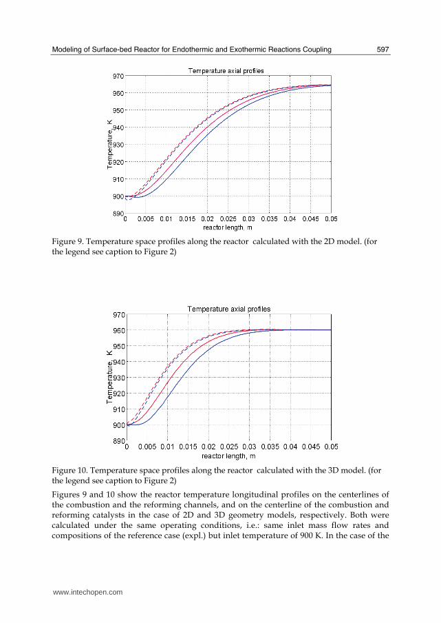
Modeling of Surface-bed Reactor for Endothermic and Exothermic Reactions Coupling
597
Figure 9 Temperature space profiles along the reactor calculated with the 2D model (for the legend see caption to Figure 2)
Figure 10 Temperature space profiles along the reactor calculated with the 3D model (for the legend see caption to Figure 2)
Figures 9 and 10 show the reactor temperature longitudinal profiles on the centerlines of the combustion and the reforming channels and on the centerline of the combustion and reforming catalysts in the case of 2D and 3D geometry models respectively Both were calculated under the same operating conditions ie same inlet mass flow rates and compositions of the reference case (expl) but inlet temperature of 900 K In the case of the
wwwintechopencom
Recent Advances in Modelling and Simulation
598
3D simulation (Figure 10) the temperature profiles are those lying over a xy plane intersecting the reactor in the middle of its height along z The two sets of profiles appear quite similar the temperatures in the combustion section (catalyst and channel) are always slightly higher than the corresponding ones in the reforming section However a closer inspection reveals some significant differences In the 2D case the temperature after an initial slow growth increases steadily from 900 K at the reactor inlet up to 965 K at the reactor outlet while in the other case it grows faster reaches 960 K at 60 of the reactor length and remains constant up to the outlet Another difference is represented by the larger transverse temperature gradients of the 3D case with respect to 2D In the 2D case they are comparable with those observed in Figure 2 for the reference case while in the 3D case they are almost double This is true for all combinations ie catalyst-catalyst catalyst-channel and channel-channel On the whole the 3D case shows a faster progress of the reactions with consequent need for faster heat transfer These differences in the thermal behaviour between 2D and 3D simulations persist when the comparison is extended to other operating conditions and in addition they reflect the better overall performance of the 3D reactor with respect to the 2D as can be seen by the following discussion The quantitative comparison between the 2D and 3D simulations was made with respect to the main results ie the methane conversion in both the combustion and the steam reforming channels as obtained from equation 5 Further beside the methane conversions other parameters are employed ie a) the gas hourly space velocities GHSV in the combustion and steam reforming sides of the reactor calculated as ratio between gas flow rates at the reactor inlet temperature and volume of catalyst b) the maximum temperature reached in the reactor c) the mean gas residence time trm in both the combustion and the reforming channel calculated as ratio between the gas flow rates at the reactor inlet temperature and the volume of the channel and d) the hydrogen yield φH2 evaluated as ratio between the amounts of methane reacted and hydrogen produced GHSV and trm were useful to allow the comparison of simulations carried out by changing the catalyst volume or the channel width as discussed later Results of simulations carried out with the 2D and 3D models under various operating conditions are reported in Table 5 Those referring to the operating conditions of the reference case are listed in the first two rows of such a Table The other operating conditions are i) same inlet temperature of the reference case but different methane concentration in the combustion channel (3rd and 4th rows of Table 5) and ii) different inlet temperatures for the two conditions above (5th-8th rows of Table 5) Focusing the comparison on the results of the simulations in 2D and 3D with the same operating conditions it appears that in general the methane conversions at the reactor outlet calculated with the 2D geometry in both the combustion and reforming channels are lower than the correspondent in 3D geometry but in one case (Xch4-sr 3rd and 4th rows of the Table) This finding reflects the differences in the thermal behaviour discussed above In any case such conversions differ by less than 10 but in the last two rows of the Table where the differences are larger It is worth noting however that even in this case the values of the conversions are congruent with the overall results of the simulation For instance the lower value of Xch4-co in the 2D with respect to the correspondent in 3D results in a lower value of Xch4-sr and in a lower maximum temperature reached in the reactor
wwwintechopencom
Modeling of Surface-bed Reactor for Endothermic and Exothermic Reactions Coupling
599
Geometry Tin K
Xch4-co Xch4-sr Tmax K Trm-co ms
Trm-sr ms
GHSVco h-1
GHSVsr h-1
φH2
2D expl 800 089 074 914 0057 0026 314840 702884 329
3D expl 800 096 077 914 0057 0026 314840 702884 333
2D n-expl 800 036 045 827 0020 0026 900588 702884 344
3D n-expl 800 040 041 828 0020 0026 900588 702884 356
2D expl 900 095 090 965 0051 0023 354194 790745 305
3D expl 900 099 093 960 0051 0023 354194 790745 300
2D n-expl 900 049 069 900 0018 0023 1013162 790745 322
3D n-expl 900 068 079 920 0018 0023 1013162 790745 318
Table 5 Comparison of 2D and 3D results obtained under the same operating conditions
For what concerns the hydrogen yield focusing again the comparison on the results of the simulations in 2D and 3D at the same operating conditions data show that φH2rsquos obtained with the 2D geometry model are lower than that in 3D model but in one case (7th and 8th row of Table 5) It is worth noting that φH2=3 would be the stoichiometric value if reaction (1) were the only occurring in the reforming catalyst so that the amount exceeding 3 is due to the contribution of reaction (2) Data in Table 5 also shows the influence on the reactor performance of temperature and inlet methane concentration in the combustion channel In the case of inlet temperature of 900 K and methane concentration within the explosivity limits (case referring to results in Figures 9 and 10) the methane conversion is practically 1 (3D model) for the combustion reaction and very high for the reforming reactions However under these conditions the hydrogen yield is the lowest In contrast when the highest hydrogen yield is reached the lowest methane conversion is achieved Similar considerations can be done for the other results in the Table so that a general trend can be drawn from such results The higher the maximum temperature reached in the reactor the higher the methane conversions and the lower the hydrogen yield
45 Influence of the channels width
The reactor thermal behaviour and performance was studied for different channels width Wc at constant inlet flow rates of the reaction mixtures Runs were also carried out by keeping constant the mean inlet velocities of reaction mixtures The variation range for the combustion channels width Wc-co was 1-15 mm and for the reforming channel width Wc-sr 2-3 mm All other parameters were kept at their reference case values Keeping constant the inlet mass flow rates and altering the channel width results in modifying the inlet velocities in the reactor and consequently the mean residence time (trm) of the gases in the channels but the GHSVrsquos do not change The results in terms of methane conversions in the combustion and reforming channels are reported in Table 6 for the reference cases (3rd and 4th row in Table) and for cases where the methane concentration in the combustion channels were below the LEL (1st and 2nd row) At constant mass flow rates the influence of the channel width or better of trm appears negligible under n-expl conditions with a slight
wwwintechopencom
Recent Advances in Modelling and Simulation
600
prevalence of the reactor with narrower channels and weak under expl conditions with in contrast better performance for the reactor with wider channels Therefore it is not possible to draw conclusions
Wc-sr mm
Tin K
Xch4 -
co Xch4-sr
Tmax K
trm-co ms
trm-sr ms
GHSVco h-1
GHSVsr h-1
2 n-expl 800 036 045 827 0020 0026 900588 702884
3 n-expl 800 034 044 819 0030 0038 900588 702884
2 expl 800 089 074 914 0057 0026 314840 702884
3 expl 800 092 081 940 0086 0038 314840 702884
Vcost- 3 n-expl 800 022 033 800 0020 0026 1350882 1054327
Table 6 Comparison between reactor performance as a function of channel width
Unlike the previous case where inlet flow rates were kept constant an increase in channel width keeping the mean gas velocity and the value of trm constants affects significantly the outlet conversions In this case the amount of reactants flowing through the reactor per unit catalyst volume and then GHSV increases (compare 1st and 5th rows in Table 5) Increasing channel widths from their reference case value (Wc-sr = 2 mm and Wc-co= 1) at constant gas inlet velocity leads to methane conversion reduction because a) the catalyst amount becomes insufficient for the amount of reactants fed in the reactor and b) the external mass transfer resistances play a stronger role The overall reaction heat fluxes remain the same as channel width increases leaving a similar amount of sensible heat to be used for heating up larger amounts of reactants This results in lower temperatures along the reactor
46 Influence of catalyst thickness
The influence of catalyst thickness c on the reactor behaviour was studied by keeping constant the reactants mass flow rates The reactor operation was simulated for three values of catalyst thickness ie 200 100 and 50 microm while keeping all the other parameters at their reference case values but for what concerns the inlet methane concentration in the combustion channel that was at non explosive level This with respect to the reference case corresponds to decreasing GHSV of factors 2 and 4 respectively Changes in the catalyst thickness influence considerably both thermal behaviour and outlet conversions As above the comparison is made through the methane conversions achieved in the two cases both in the steam reforming and in the combustion channels The results are reported in Table 7 It is evident that the loss of performance due to a decrease of 50 of c from 200 to 100 μm is almost negligible This is mainly due to the conservative parameters used for defining the catalyst layer characteristics (ie mean pore radius and tortuosity) that results in a very impervious path for diffusing gases However when c is further decreased methane conversion both in the combustion and in the reforming section significantly decrease The hydrogen yield does not change too much within the limits of the three cases analyzed
wwwintechopencom
Modeling of Surface-bed Reactor for Endothermic and Exothermic Reactions Coupling
601
δc μm
Tin K Xch4 -co Xch4-sr Tmax Ktrm-co ms
trm-sr ms
GHSVco h-1
GHSVsr h-1
φH2
200 n-expl 800 036 045 827 0020 0026 900588 702884 344
100 n-expl 800 035 045 827 0020 0026 1801176 1405768 344
50 n-expl 800 027 038 800 0020 0026 3602352 2811536 342
Table 7 Comparison between reactor performance as a function of catalyst thickness
5 Discussion
As seen in the previous section (4) there are several operating parameters that influence the performances of the system They are typical of reacting systems and can be summarized as GHSVrsquos tmrrsquos and inlet gas temperatures The particularity of the present case is the simultaneous occurrence of two coupled reactions one exothermic and the other endothermic in which the extent of the second depends on the extent (heat produced) of the first and the effectiveness of the heat transferred In addition the coupling of the two reactions does not exclude to have for each set of values of the mentioned parameters pertaining to one reaction several sets of parameters for the other reaction This makes the system quite complex and difficult to analyze However some general considerations can be drawn
Figure 11 Methane conversions in the combustion and reforming sides of the reactor as a function of GHSV for various operating conditions available in Table 6 and 7
The first is that as expected GHVS plays a key role in determining the reactor performances although this is supported by only a part of the data For instance data in Table 7 pertaining to simulations of the influence of such a parameter carried out by changing GHSV in the same way for both sections of the reacting system shows a clear effect of GHSV the reactor
0 1000000 2000000 3000000 4000000
GHSV h-1
02
04
06
08
1
XC
H4
-co a
nd
XC
H4
-sr -
data from Table 7 comb side
data from Table 7 refor side
data from Table 6 comb side
data from Table 6 refor side
wwwintechopencom
Recent Advances in Modelling and Simulation
602
performance decreases as GHSV increases on both sides of the reactor Such an influence does not appear strong the conversion change being about 20 against GHSV variations of a factor 4 (Figure 11) The influence of GHSV is more evident from data in Table 6 pertaining to simulations of the influence of tmr In fact also in this case a clear trend appears and the influence even though in the same direction of the previous case appears much stronger since with respect to a GHSV change of about 20 the methane conversion varies by a factor 4 (Figure 11) Such a strong influence is due to the combined effect of tmr especially on the combustion side of the reactor (cfr Table 6) Instead for data in Table 5 pertaining to simulations of the reliability of 2D and 3D models and the effect of gas inlet temperature it is not possible to highlight a clear influence The comparison between the results obtained with the 2D and 3D models under the same operating conditions have evidenced differences in the performance of the reactor not large but significant When we move from 2D to 3D models such differences result in an increase from 5 to 20 of both Xch4-co and Xch4-sr which reflects a different thermal behavior of the reacting system and influence also the hydrogen yield It is worth noting that the computation time required in the two cases is very different Specifically using an HP xw8400workstation equipped with 2 Xeon processors and 4 GB of RAM a 2D simulation takes on the average about 20 minutes with respect to 50-60 hours necessary in the 3D case It is impossible by now to establish which is the more correct or the more reliable In particular it should be assessed if 2D simulations are suitable for purpose of reactor design and experimental data interpretation The answer should come from the comparison of the results of such simulations with experimental data obtained with a real reactor geometrically comparable operated under conditions as much as similar to those fixed for the simulations This represents argument for coming work of the authors Further interesting aspects to be studied are the simulation of unsteady-state conditions and specifically of the system start-up and of the system response to small changes in the gas feeding flow rates and temperatures
6 Conclusions
Methane steam reforming coupled with methane catalytic combustion by means of indirect heat transfer in a surface-bed catalytic reactor was studied by 2D and 3D models The reactor consists of a central reforming channel and two lateral combustion channels A reference case for what concerns operating conditions and reactor geometry was chosen and its simulation was carried out Changes of reactor performance as consequence of operating parameters and reactor geometry variations were analyzed with respect to the reference case The simulation showed that suitable amount of fuel and adequate catalyst activity in the combustion channel can provide enough heat to simultaneously heat up the reaction mixture and drive the endothermic process The proximity between the heat source and the heat sink increases the efficiency of heat transfer resulting in transverse temperature gradients do not exceeding generally 07 K across the metallic wall and 20 K across the gas in the channel Decrease of transverse temperature differences and intraphase mass transfer resistances have the global effect of reducing the reactor dimension and the catalyst amount The influence of channels width and catalyst layer thickness on reactor behaviour was also studied At constant inlet flow rates changes of channel width in the range 1ndash2 mm do not introduce significant differences in the reactor performance Rather small differences in the
wwwintechopencom
Modeling of Surface-bed Reactor for Endothermic and Exothermic Reactions Coupling
603
catalyst axial temperature profiles and outlet methane conversions are observed In contrast altering the channel width at constant inlet velocities has strong influence Larger channel width results in lower conversion and smoother axial temperature profiles Intraphase resistances are present even for catalyst thickness of micrometers for both reforming and combustion processes Increasing GHSV that is the inlet flow ratecatalyst volume ratio leads to lower outlet conversions Due to different effect of catalyst layer thickness on reforming and combustion channels there are significant changes in the reactor temperature profile Results indicate that steam reforming of methane in a surface-bed reactor is feasible provided that mass flow rates channels width catalyst loadings and thickness are properly designed
7 Notation
cp specific heat J(mol K) c concentration molm3 Deff effective diffusion coefficient m2s D molecular diffusion coefficient m2s GHSV gas hourly space velocity h-1 k thermal conductivity W(m K) or reaction rate constant Ke equilibrium constant M molecular weight kgmol LEL lower explosivity limit vol
unit vector perpendicular to the flux surface
N molar flux at the boundary mol(m2 s) p partial pressure bar P total pressure bar q thermal flux at the boundary J(m2 s) r reaction rate various dimensions (see eqs 1rsquo 2rsquo and 3rsquo) Rp catalyst pore radius nm STP standard temperature and pressure (298 K and 101 103 Pa) t time s T temperature K ts transverse surface ux Velocity component on the x coordinate
velocity vector
v normal component of velocity at the channel ingress x axial coordinate m X conversion y transverse coordinate m Wc distance between the reactor plates m z vertical coordinate m Greek letters ΔH0r heat of reaction at reference state conditions KJmol c catalyst thickness μm catalyst porosity φ atomic diffusion volume or chemical reaction yield
wwwintechopencom
Recent Advances in Modelling and Simulation
604
θ stoichiometric coefficient ρ density kgm3 τ catalyst tortuosity
Subscripts and superscripts cat catalyst co combustion CH4 methane H2 hydrogen in inlet i chemical species j channel k reaction l phase rm mean residence s metal sheet sr steam reforming 0 channel ingress 1 reforming reaction 2 water gas shift reaction 3 combustion reaction
8 Acknowledgements
The authors gratefully acknowledge the financial support of MIUR under grant PRIN ndeg 2006094333004
9 References
Akers WW amp Camp DP (1955) Kinetics of the methanendashsteam reaction AIChE Journal Vol 1 471ndash475 ISSN0001-1541
Allen DW Gerhard ER amp Likins Jr MR (1975) Kinetics of the MethanendashSteam Reaction Ind Eng Chem Proc Des Dev Vol 14 No 3 256-259 ISSN0196-4305
Aparicio L (1997) Transient Isotopic Studies and Microkinetic Modeling of Methane Reforming over Nickel Catalysts Journal of Catal Vol 165 No 2 262-274 ISSN 0021-9517
Avci AK Trimm DL amp İlsen Oumlnsan Z (2001) Heterogeneous reactor modeling for simulation of catalytic oxidation and steam reforming of methane Chem Eng Sci Vol 56 No 2 641-649 ISSN0009-2509
Bridger GW (1980) The steam reforming of hydrocarbons Catalysis Vol 3 39-69 ISSN0140-0568
Cao C Wang Y amp Rozmiarek RT (2005) Heterogeneous reactor model for steam reforming of methane in a microchannel reactor with microstructured catalysts Catal Today Vol 110 No 1-2 92ndash97 ISSN 0920-5861
Craciun R Shereck B amp Gorte RJ (1998) Kinetic studies of methane steam reforming on ceria-supported Pd Catal Lett Vol 51 No 3ndash4 149-153 ISSN 1011-372x
wwwintechopencom
Modeling of Surface-bed Reactor for Endothermic and Exothermic Reactions Coupling
605
Crowl DA amp Louvar JF (2002) Chemical Process Safety fundamentals with applications 2nd ed Prentice Hall PTR Upper Saddle River NJ USA ISBN 0-13mdash018176-5
De Deken J C Devos E F amp Froment G F (1982) Steam reforming of natural gas Intrinsic kinetics diffusional influences and reactor design ACS Symposium Series 196 181ndash197 ISSN0097-6156
Ehrfeld W amp Hessel V Lowe H (2000) Microreactor Wiley-VCH Verlag GmbH D-69469 ISBN Weinheim Germany
Gosiewski K (2001) Simulations of non-stationary reactors for catalytic conversion of methane to synthesis gas Chem Eng Sci Vol 56 No 4 1501-1510 ISSN
Groppi G Belloli A Tronconi E Forzatti P (1995) A comparison of lumped and distributed models of monolith catalytic combustors Chem Eng Sci Vol 50 No 17 2705ndash2715 ISSN0009-2509
Holladay JD Wang Y amp Jones E (2004) Review of Developments in Portable Hydrogen Production Using Microreactor Technology Chem Rev Vol 104 No 10 4767-4790 ISSN 0009-2665
Hou K amp Hughes R (2001) The kinetics of methane steam reforming over a Ni-Al2O3 catalyst Chem Eng Journal Vol 82 No 1-3 311-328 ISSN 1385-8947
Jamal Y amp Wyszynski M L (1994) On-board generation of hydrogen-rich gaseous fuels a review Int J of Hydrogen Energy Vol 19 No 7 557-572 ISSN 0360-3199
Jensen KF (2001) Microreaction engineering is small better Chem Eng Sci Vol 56 No 2 293-303 ISSN0009-2509
Kolios G Gritsch A Glo1ckler B amp Sorescu G (2004) Novel Reactor Concepts for Thermally Efficient Methane Steam Reforming Modeling and Simulation Ind Eng Chem Res Vol 43 No 16 4796-4808 ISSN0888-5885
Kruger P Blakeley J amp Leaver J (2003) Potential in New Zealand for use of hydrogen as a transportation fuel Int J of Hydrogen Energy Vol 28 No 8 795ndash802 ISSN 0360-3199
Kvamsdal HM Svendsen HF Hertzberg T amp Olsvik O (1999) Dynamic simulation and optimization of a catalytic steam reformer Chem Eng Sci Vol 54 No 13-14 2697-2706 ISSN0009-2509
Lerer M Duic N Alves LM amp Carvalho MG (2006) H2 RES energy planning tool for increasing the penetration of renewable energy sources in island energy supply In New and Renewable Technologies for Sustanaible Development MG Carvalho and NH Afgan (Ed s) 15-30 World Scientific ISBN 10 981-270-505-8 Singapore
Lerou JJ amp Ng KM (1996) Chemical reaction engineering A multiscale approach to a multiobjective task Chem Eng Sci Vol 51 No 10 1595-1614 ISSN0009-2509
Lincoln SF (2006) Challenged Earth ch7 Imperial College Press ISBN 1-86094-526-0 London
Loffler D G Faz C F Sokolovskii V amp Iglesia E (2002) Catalytic separator plate reactor and method of catalytic reforming of fuel to Hydrogen PCT Int Appl WO 0228769 A2
Luna C amp Becerra AM (1997) Kinetics of methane steam reforming on a Ni on alumina-titania catalyst React Kinet Catal Lett Vol 61 No 2 369-374 ISSN 0133-1736
Marschner F Renner HJ amp Boll W (2005) Electronic Encyclopedia Release 2005 7th ed in Ullmannrsquos Encyclopedia of Industrial Chemistry M Bohnet et al (Eds) Vol a12 John Wiley amp Sons ISBN-13 978-3-527-30385-4
wwwintechopencom
Recent Advances in Modelling and Simulation
606
Moore R B amp Raman V (1998) Hydrogen infrastructure for fuel cell transportation Int J of Hydrogen Energy Vol 23 No 7 617-620 ISSN 0360-3199
Perry RH amp Green DW (1999) Perrys Chemical Engineers Handbook (7th Ed) McGraw-Hill ISBN 0-07-049841-5
Robbins F A Zhu H amp Jackson GS (2003) Transient modeling of combined catalytic combustionCH4 steam reformng Catal Today Vol 83 No 1-4 141ndash156 ISSN 0920-5861
Rostrup-Nielsen JR Christiansen LJ amp BakHansen JH (1988) Activity of steam reforming catalysts Role and assessment Appl Catal Vol 43 No 2 287-303 ISSN0166-9834
Rostrup-Nielsen JR (1995) Innovation and the catalytic process industry - the science and challenge Chem Eng Sci Vol 50 No 24 4061-4071 ISSN0009-2509
Rostrup-Nielsen JR Dybkjaer I amp Coulthard GRG (2001) Topical Conf Proc AIChE Spring National Meeting Houston TX April Paper No 1
Rostrup-Nielsen JR (2004) Fuels and Energy for the Future The Role of Catalysis Catal Rev - Science and Engineering Vol 46 No 3ndash4 247-270 ISSN0161-4940
Schubert K Brandner J Fichtner M Linder G Schyhulla U amp Wenka A (2001) Microstructure devices for applications in thermal and chemical process engineering Microscale Thermophys Eng Vol 5 No 1 17-39 ISSN1089-3954
Tronconi E amp Groppi G (2000) A study on the thermal behavior of structured plate-type catalysts with metallic supports for gassolid exothermic reactions Chem Eng Sci Vol 55 Issue 24 December 6021-6036 ISSN0009-2509
Wang Y Johnson BR Cao C Chin Y Rozmiarek RT Gao Y Tonkovich AL (2005) Engineered catalysts for microchannel reactor applications In Microreactor Technology and Process Intensification Y Wang J Holladay (Eds) 65-73 ACS Symposium Series Vol 914 ISBN-13 9780841239234
Xu J amp Froment GF (1989a) Methane steam reforming II Diffusional limitations and reactor simulation AIChE Journal Vol 35 No 1 97-103 ISSN0001-1541
Xu J amp Froment GF (1989b) Methane steam reforming methanation and water-gas shift I Intrinsic kinetics AIChE Journal Vol 35 No 1 88-96 ISSN0001-1541
Zanfir M amp Gavriilidis A (2003) Catalytic Combustion Assisted Methane Steam Reforming Chem Eng Sci Vol 58 No 17 3947ndash 3960 ISSN0009-2509
wwwintechopencom
Modelling and SimulationEdited by Giuseppe Petrone and Giuliano Cammarata
ISBN 978-3-902613-25-7Hard cover 688 pagesPublisher I-Tech Education and PublishingPublished online 01 June 2008Published in print edition June 2008
InTech EuropeUniversity Campus STeP Ri Slavka Krautzeka 83A 51000 Rijeka Croatia Phone +385 (51) 770 447 Fax +385 (51) 686 166wwwintechopencom
InTech ChinaUnit 405 Office Block Hotel Equatorial Shanghai No65 Yan An Road (West) Shanghai 200040 China
Phone +86-21-62489820 Fax +86-21-62489821
This book collects original and innovative research studies concerning modeling and simulation of physicalsystems in a very wide range of applications encompassing micro-electro-mechanical systems measurementinstrumentations catalytic reactors biomechanical applications biological and chemical sensorsmagnetosensitive materials silicon photonic devices electronic devices optical fibers electro-microfluidicsystems composite materials fuel cells indoor air-conditioning systems active magnetic levitation systemsand more Some of the most recent numerical techniques as well as some of the software among the mostaccurate and sophisticated in treating complex systems are applied in order to exhaustively contribute inknowledge advances
How to referenceIn order to correctly reference this scholarly work feel free to copy and paste the following
Salvatore Vaccaro and Paolo Ciambelli (2008) Modeling of Surface-bed Reactor for Endothermic andExothermic Reactions Coupling Modelling and Simulation Giuseppe Petrone and Giuliano Cammarata (Ed)ISBN 978-3-902613-25-7 InTech Available fromhttpwwwintechopencombooksmodelling_and_simulationmodeling_of_surface-bed_reactor_for_endothermic_and_exothermic_reactions_coupling
copy 2008 The Author(s) Licensee IntechOpen This chapter is distributedunder the terms of the Creative Commons Attribution-NonCommercial-ShareAlike-30 License which permits use distribution and reproduction fornon-commercial purposes provided the original is properly cited andderivative works building on this content are distributed under the samelicense
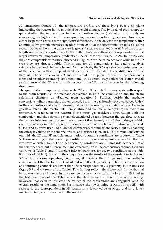
Recent Advances in Modelling and Simulation
598
3D simulation (Figure 10) the temperature profiles are those lying over a xy plane intersecting the reactor in the middle of its height along z The two sets of profiles appear quite similar the temperatures in the combustion section (catalyst and channel) are always slightly higher than the corresponding ones in the reforming section However a closer inspection reveals some significant differences In the 2D case the temperature after an initial slow growth increases steadily from 900 K at the reactor inlet up to 965 K at the reactor outlet while in the other case it grows faster reaches 960 K at 60 of the reactor length and remains constant up to the outlet Another difference is represented by the larger transverse temperature gradients of the 3D case with respect to 2D In the 2D case they are comparable with those observed in Figure 2 for the reference case while in the 3D case they are almost double This is true for all combinations ie catalyst-catalyst catalyst-channel and channel-channel On the whole the 3D case shows a faster progress of the reactions with consequent need for faster heat transfer These differences in the thermal behaviour between 2D and 3D simulations persist when the comparison is extended to other operating conditions and in addition they reflect the better overall performance of the 3D reactor with respect to the 2D as can be seen by the following discussion The quantitative comparison between the 2D and 3D simulations was made with respect to the main results ie the methane conversion in both the combustion and the steam reforming channels as obtained from equation 5 Further beside the methane conversions other parameters are employed ie a) the gas hourly space velocities GHSV in the combustion and steam reforming sides of the reactor calculated as ratio between gas flow rates at the reactor inlet temperature and volume of catalyst b) the maximum temperature reached in the reactor c) the mean gas residence time trm in both the combustion and the reforming channel calculated as ratio between the gas flow rates at the reactor inlet temperature and the volume of the channel and d) the hydrogen yield φH2 evaluated as ratio between the amounts of methane reacted and hydrogen produced GHSV and trm were useful to allow the comparison of simulations carried out by changing the catalyst volume or the channel width as discussed later Results of simulations carried out with the 2D and 3D models under various operating conditions are reported in Table 5 Those referring to the operating conditions of the reference case are listed in the first two rows of such a Table The other operating conditions are i) same inlet temperature of the reference case but different methane concentration in the combustion channel (3rd and 4th rows of Table 5) and ii) different inlet temperatures for the two conditions above (5th-8th rows of Table 5) Focusing the comparison on the results of the simulations in 2D and 3D with the same operating conditions it appears that in general the methane conversions at the reactor outlet calculated with the 2D geometry in both the combustion and reforming channels are lower than the correspondent in 3D geometry but in one case (Xch4-sr 3rd and 4th rows of the Table) This finding reflects the differences in the thermal behaviour discussed above In any case such conversions differ by less than 10 but in the last two rows of the Table where the differences are larger It is worth noting however that even in this case the values of the conversions are congruent with the overall results of the simulation For instance the lower value of Xch4-co in the 2D with respect to the correspondent in 3D results in a lower value of Xch4-sr and in a lower maximum temperature reached in the reactor
wwwintechopencom
Modeling of Surface-bed Reactor for Endothermic and Exothermic Reactions Coupling
599
Geometry Tin K
Xch4-co Xch4-sr Tmax K Trm-co ms
Trm-sr ms
GHSVco h-1
GHSVsr h-1
φH2
2D expl 800 089 074 914 0057 0026 314840 702884 329
3D expl 800 096 077 914 0057 0026 314840 702884 333
2D n-expl 800 036 045 827 0020 0026 900588 702884 344
3D n-expl 800 040 041 828 0020 0026 900588 702884 356
2D expl 900 095 090 965 0051 0023 354194 790745 305
3D expl 900 099 093 960 0051 0023 354194 790745 300
2D n-expl 900 049 069 900 0018 0023 1013162 790745 322
3D n-expl 900 068 079 920 0018 0023 1013162 790745 318
Table 5 Comparison of 2D and 3D results obtained under the same operating conditions
For what concerns the hydrogen yield focusing again the comparison on the results of the simulations in 2D and 3D at the same operating conditions data show that φH2rsquos obtained with the 2D geometry model are lower than that in 3D model but in one case (7th and 8th row of Table 5) It is worth noting that φH2=3 would be the stoichiometric value if reaction (1) were the only occurring in the reforming catalyst so that the amount exceeding 3 is due to the contribution of reaction (2) Data in Table 5 also shows the influence on the reactor performance of temperature and inlet methane concentration in the combustion channel In the case of inlet temperature of 900 K and methane concentration within the explosivity limits (case referring to results in Figures 9 and 10) the methane conversion is practically 1 (3D model) for the combustion reaction and very high for the reforming reactions However under these conditions the hydrogen yield is the lowest In contrast when the highest hydrogen yield is reached the lowest methane conversion is achieved Similar considerations can be done for the other results in the Table so that a general trend can be drawn from such results The higher the maximum temperature reached in the reactor the higher the methane conversions and the lower the hydrogen yield
45 Influence of the channels width
The reactor thermal behaviour and performance was studied for different channels width Wc at constant inlet flow rates of the reaction mixtures Runs were also carried out by keeping constant the mean inlet velocities of reaction mixtures The variation range for the combustion channels width Wc-co was 1-15 mm and for the reforming channel width Wc-sr 2-3 mm All other parameters were kept at their reference case values Keeping constant the inlet mass flow rates and altering the channel width results in modifying the inlet velocities in the reactor and consequently the mean residence time (trm) of the gases in the channels but the GHSVrsquos do not change The results in terms of methane conversions in the combustion and reforming channels are reported in Table 6 for the reference cases (3rd and 4th row in Table) and for cases where the methane concentration in the combustion channels were below the LEL (1st and 2nd row) At constant mass flow rates the influence of the channel width or better of trm appears negligible under n-expl conditions with a slight
wwwintechopencom
Recent Advances in Modelling and Simulation
600
prevalence of the reactor with narrower channels and weak under expl conditions with in contrast better performance for the reactor with wider channels Therefore it is not possible to draw conclusions
Wc-sr mm
Tin K
Xch4 -
co Xch4-sr
Tmax K
trm-co ms
trm-sr ms
GHSVco h-1
GHSVsr h-1
2 n-expl 800 036 045 827 0020 0026 900588 702884
3 n-expl 800 034 044 819 0030 0038 900588 702884
2 expl 800 089 074 914 0057 0026 314840 702884
3 expl 800 092 081 940 0086 0038 314840 702884
Vcost- 3 n-expl 800 022 033 800 0020 0026 1350882 1054327
Table 6 Comparison between reactor performance as a function of channel width
Unlike the previous case where inlet flow rates were kept constant an increase in channel width keeping the mean gas velocity and the value of trm constants affects significantly the outlet conversions In this case the amount of reactants flowing through the reactor per unit catalyst volume and then GHSV increases (compare 1st and 5th rows in Table 5) Increasing channel widths from their reference case value (Wc-sr = 2 mm and Wc-co= 1) at constant gas inlet velocity leads to methane conversion reduction because a) the catalyst amount becomes insufficient for the amount of reactants fed in the reactor and b) the external mass transfer resistances play a stronger role The overall reaction heat fluxes remain the same as channel width increases leaving a similar amount of sensible heat to be used for heating up larger amounts of reactants This results in lower temperatures along the reactor
46 Influence of catalyst thickness
The influence of catalyst thickness c on the reactor behaviour was studied by keeping constant the reactants mass flow rates The reactor operation was simulated for three values of catalyst thickness ie 200 100 and 50 microm while keeping all the other parameters at their reference case values but for what concerns the inlet methane concentration in the combustion channel that was at non explosive level This with respect to the reference case corresponds to decreasing GHSV of factors 2 and 4 respectively Changes in the catalyst thickness influence considerably both thermal behaviour and outlet conversions As above the comparison is made through the methane conversions achieved in the two cases both in the steam reforming and in the combustion channels The results are reported in Table 7 It is evident that the loss of performance due to a decrease of 50 of c from 200 to 100 μm is almost negligible This is mainly due to the conservative parameters used for defining the catalyst layer characteristics (ie mean pore radius and tortuosity) that results in a very impervious path for diffusing gases However when c is further decreased methane conversion both in the combustion and in the reforming section significantly decrease The hydrogen yield does not change too much within the limits of the three cases analyzed
wwwintechopencom
Modeling of Surface-bed Reactor for Endothermic and Exothermic Reactions Coupling
601
δc μm
Tin K Xch4 -co Xch4-sr Tmax Ktrm-co ms
trm-sr ms
GHSVco h-1
GHSVsr h-1
φH2
200 n-expl 800 036 045 827 0020 0026 900588 702884 344
100 n-expl 800 035 045 827 0020 0026 1801176 1405768 344
50 n-expl 800 027 038 800 0020 0026 3602352 2811536 342
Table 7 Comparison between reactor performance as a function of catalyst thickness
5 Discussion
As seen in the previous section (4) there are several operating parameters that influence the performances of the system They are typical of reacting systems and can be summarized as GHSVrsquos tmrrsquos and inlet gas temperatures The particularity of the present case is the simultaneous occurrence of two coupled reactions one exothermic and the other endothermic in which the extent of the second depends on the extent (heat produced) of the first and the effectiveness of the heat transferred In addition the coupling of the two reactions does not exclude to have for each set of values of the mentioned parameters pertaining to one reaction several sets of parameters for the other reaction This makes the system quite complex and difficult to analyze However some general considerations can be drawn
Figure 11 Methane conversions in the combustion and reforming sides of the reactor as a function of GHSV for various operating conditions available in Table 6 and 7
The first is that as expected GHVS plays a key role in determining the reactor performances although this is supported by only a part of the data For instance data in Table 7 pertaining to simulations of the influence of such a parameter carried out by changing GHSV in the same way for both sections of the reacting system shows a clear effect of GHSV the reactor
0 1000000 2000000 3000000 4000000
GHSV h-1
02
04
06
08
1
XC
H4
-co a
nd
XC
H4
-sr -
data from Table 7 comb side
data from Table 7 refor side
data from Table 6 comb side
data from Table 6 refor side
wwwintechopencom
Recent Advances in Modelling and Simulation
602
performance decreases as GHSV increases on both sides of the reactor Such an influence does not appear strong the conversion change being about 20 against GHSV variations of a factor 4 (Figure 11) The influence of GHSV is more evident from data in Table 6 pertaining to simulations of the influence of tmr In fact also in this case a clear trend appears and the influence even though in the same direction of the previous case appears much stronger since with respect to a GHSV change of about 20 the methane conversion varies by a factor 4 (Figure 11) Such a strong influence is due to the combined effect of tmr especially on the combustion side of the reactor (cfr Table 6) Instead for data in Table 5 pertaining to simulations of the reliability of 2D and 3D models and the effect of gas inlet temperature it is not possible to highlight a clear influence The comparison between the results obtained with the 2D and 3D models under the same operating conditions have evidenced differences in the performance of the reactor not large but significant When we move from 2D to 3D models such differences result in an increase from 5 to 20 of both Xch4-co and Xch4-sr which reflects a different thermal behavior of the reacting system and influence also the hydrogen yield It is worth noting that the computation time required in the two cases is very different Specifically using an HP xw8400workstation equipped with 2 Xeon processors and 4 GB of RAM a 2D simulation takes on the average about 20 minutes with respect to 50-60 hours necessary in the 3D case It is impossible by now to establish which is the more correct or the more reliable In particular it should be assessed if 2D simulations are suitable for purpose of reactor design and experimental data interpretation The answer should come from the comparison of the results of such simulations with experimental data obtained with a real reactor geometrically comparable operated under conditions as much as similar to those fixed for the simulations This represents argument for coming work of the authors Further interesting aspects to be studied are the simulation of unsteady-state conditions and specifically of the system start-up and of the system response to small changes in the gas feeding flow rates and temperatures
6 Conclusions
Methane steam reforming coupled with methane catalytic combustion by means of indirect heat transfer in a surface-bed catalytic reactor was studied by 2D and 3D models The reactor consists of a central reforming channel and two lateral combustion channels A reference case for what concerns operating conditions and reactor geometry was chosen and its simulation was carried out Changes of reactor performance as consequence of operating parameters and reactor geometry variations were analyzed with respect to the reference case The simulation showed that suitable amount of fuel and adequate catalyst activity in the combustion channel can provide enough heat to simultaneously heat up the reaction mixture and drive the endothermic process The proximity between the heat source and the heat sink increases the efficiency of heat transfer resulting in transverse temperature gradients do not exceeding generally 07 K across the metallic wall and 20 K across the gas in the channel Decrease of transverse temperature differences and intraphase mass transfer resistances have the global effect of reducing the reactor dimension and the catalyst amount The influence of channels width and catalyst layer thickness on reactor behaviour was also studied At constant inlet flow rates changes of channel width in the range 1ndash2 mm do not introduce significant differences in the reactor performance Rather small differences in the
wwwintechopencom
Modeling of Surface-bed Reactor for Endothermic and Exothermic Reactions Coupling
603
catalyst axial temperature profiles and outlet methane conversions are observed In contrast altering the channel width at constant inlet velocities has strong influence Larger channel width results in lower conversion and smoother axial temperature profiles Intraphase resistances are present even for catalyst thickness of micrometers for both reforming and combustion processes Increasing GHSV that is the inlet flow ratecatalyst volume ratio leads to lower outlet conversions Due to different effect of catalyst layer thickness on reforming and combustion channels there are significant changes in the reactor temperature profile Results indicate that steam reforming of methane in a surface-bed reactor is feasible provided that mass flow rates channels width catalyst loadings and thickness are properly designed
7 Notation
cp specific heat J(mol K) c concentration molm3 Deff effective diffusion coefficient m2s D molecular diffusion coefficient m2s GHSV gas hourly space velocity h-1 k thermal conductivity W(m K) or reaction rate constant Ke equilibrium constant M molecular weight kgmol LEL lower explosivity limit vol
unit vector perpendicular to the flux surface
N molar flux at the boundary mol(m2 s) p partial pressure bar P total pressure bar q thermal flux at the boundary J(m2 s) r reaction rate various dimensions (see eqs 1rsquo 2rsquo and 3rsquo) Rp catalyst pore radius nm STP standard temperature and pressure (298 K and 101 103 Pa) t time s T temperature K ts transverse surface ux Velocity component on the x coordinate
velocity vector
v normal component of velocity at the channel ingress x axial coordinate m X conversion y transverse coordinate m Wc distance between the reactor plates m z vertical coordinate m Greek letters ΔH0r heat of reaction at reference state conditions KJmol c catalyst thickness μm catalyst porosity φ atomic diffusion volume or chemical reaction yield
wwwintechopencom
Recent Advances in Modelling and Simulation
604
θ stoichiometric coefficient ρ density kgm3 τ catalyst tortuosity
Subscripts and superscripts cat catalyst co combustion CH4 methane H2 hydrogen in inlet i chemical species j channel k reaction l phase rm mean residence s metal sheet sr steam reforming 0 channel ingress 1 reforming reaction 2 water gas shift reaction 3 combustion reaction
8 Acknowledgements
The authors gratefully acknowledge the financial support of MIUR under grant PRIN ndeg 2006094333004
9 References
Akers WW amp Camp DP (1955) Kinetics of the methanendashsteam reaction AIChE Journal Vol 1 471ndash475 ISSN0001-1541
Allen DW Gerhard ER amp Likins Jr MR (1975) Kinetics of the MethanendashSteam Reaction Ind Eng Chem Proc Des Dev Vol 14 No 3 256-259 ISSN0196-4305
Aparicio L (1997) Transient Isotopic Studies and Microkinetic Modeling of Methane Reforming over Nickel Catalysts Journal of Catal Vol 165 No 2 262-274 ISSN 0021-9517
Avci AK Trimm DL amp İlsen Oumlnsan Z (2001) Heterogeneous reactor modeling for simulation of catalytic oxidation and steam reforming of methane Chem Eng Sci Vol 56 No 2 641-649 ISSN0009-2509
Bridger GW (1980) The steam reforming of hydrocarbons Catalysis Vol 3 39-69 ISSN0140-0568
Cao C Wang Y amp Rozmiarek RT (2005) Heterogeneous reactor model for steam reforming of methane in a microchannel reactor with microstructured catalysts Catal Today Vol 110 No 1-2 92ndash97 ISSN 0920-5861
Craciun R Shereck B amp Gorte RJ (1998) Kinetic studies of methane steam reforming on ceria-supported Pd Catal Lett Vol 51 No 3ndash4 149-153 ISSN 1011-372x
wwwintechopencom
Modeling of Surface-bed Reactor for Endothermic and Exothermic Reactions Coupling
605
Crowl DA amp Louvar JF (2002) Chemical Process Safety fundamentals with applications 2nd ed Prentice Hall PTR Upper Saddle River NJ USA ISBN 0-13mdash018176-5
De Deken J C Devos E F amp Froment G F (1982) Steam reforming of natural gas Intrinsic kinetics diffusional influences and reactor design ACS Symposium Series 196 181ndash197 ISSN0097-6156
Ehrfeld W amp Hessel V Lowe H (2000) Microreactor Wiley-VCH Verlag GmbH D-69469 ISBN Weinheim Germany
Gosiewski K (2001) Simulations of non-stationary reactors for catalytic conversion of methane to synthesis gas Chem Eng Sci Vol 56 No 4 1501-1510 ISSN
Groppi G Belloli A Tronconi E Forzatti P (1995) A comparison of lumped and distributed models of monolith catalytic combustors Chem Eng Sci Vol 50 No 17 2705ndash2715 ISSN0009-2509
Holladay JD Wang Y amp Jones E (2004) Review of Developments in Portable Hydrogen Production Using Microreactor Technology Chem Rev Vol 104 No 10 4767-4790 ISSN 0009-2665
Hou K amp Hughes R (2001) The kinetics of methane steam reforming over a Ni-Al2O3 catalyst Chem Eng Journal Vol 82 No 1-3 311-328 ISSN 1385-8947
Jamal Y amp Wyszynski M L (1994) On-board generation of hydrogen-rich gaseous fuels a review Int J of Hydrogen Energy Vol 19 No 7 557-572 ISSN 0360-3199
Jensen KF (2001) Microreaction engineering is small better Chem Eng Sci Vol 56 No 2 293-303 ISSN0009-2509
Kolios G Gritsch A Glo1ckler B amp Sorescu G (2004) Novel Reactor Concepts for Thermally Efficient Methane Steam Reforming Modeling and Simulation Ind Eng Chem Res Vol 43 No 16 4796-4808 ISSN0888-5885
Kruger P Blakeley J amp Leaver J (2003) Potential in New Zealand for use of hydrogen as a transportation fuel Int J of Hydrogen Energy Vol 28 No 8 795ndash802 ISSN 0360-3199
Kvamsdal HM Svendsen HF Hertzberg T amp Olsvik O (1999) Dynamic simulation and optimization of a catalytic steam reformer Chem Eng Sci Vol 54 No 13-14 2697-2706 ISSN0009-2509
Lerer M Duic N Alves LM amp Carvalho MG (2006) H2 RES energy planning tool for increasing the penetration of renewable energy sources in island energy supply In New and Renewable Technologies for Sustanaible Development MG Carvalho and NH Afgan (Ed s) 15-30 World Scientific ISBN 10 981-270-505-8 Singapore
Lerou JJ amp Ng KM (1996) Chemical reaction engineering A multiscale approach to a multiobjective task Chem Eng Sci Vol 51 No 10 1595-1614 ISSN0009-2509
Lincoln SF (2006) Challenged Earth ch7 Imperial College Press ISBN 1-86094-526-0 London
Loffler D G Faz C F Sokolovskii V amp Iglesia E (2002) Catalytic separator plate reactor and method of catalytic reforming of fuel to Hydrogen PCT Int Appl WO 0228769 A2
Luna C amp Becerra AM (1997) Kinetics of methane steam reforming on a Ni on alumina-titania catalyst React Kinet Catal Lett Vol 61 No 2 369-374 ISSN 0133-1736
Marschner F Renner HJ amp Boll W (2005) Electronic Encyclopedia Release 2005 7th ed in Ullmannrsquos Encyclopedia of Industrial Chemistry M Bohnet et al (Eds) Vol a12 John Wiley amp Sons ISBN-13 978-3-527-30385-4
wwwintechopencom
Recent Advances in Modelling and Simulation
606
Moore R B amp Raman V (1998) Hydrogen infrastructure for fuel cell transportation Int J of Hydrogen Energy Vol 23 No 7 617-620 ISSN 0360-3199
Perry RH amp Green DW (1999) Perrys Chemical Engineers Handbook (7th Ed) McGraw-Hill ISBN 0-07-049841-5
Robbins F A Zhu H amp Jackson GS (2003) Transient modeling of combined catalytic combustionCH4 steam reformng Catal Today Vol 83 No 1-4 141ndash156 ISSN 0920-5861
Rostrup-Nielsen JR Christiansen LJ amp BakHansen JH (1988) Activity of steam reforming catalysts Role and assessment Appl Catal Vol 43 No 2 287-303 ISSN0166-9834
Rostrup-Nielsen JR (1995) Innovation and the catalytic process industry - the science and challenge Chem Eng Sci Vol 50 No 24 4061-4071 ISSN0009-2509
Rostrup-Nielsen JR Dybkjaer I amp Coulthard GRG (2001) Topical Conf Proc AIChE Spring National Meeting Houston TX April Paper No 1
Rostrup-Nielsen JR (2004) Fuels and Energy for the Future The Role of Catalysis Catal Rev - Science and Engineering Vol 46 No 3ndash4 247-270 ISSN0161-4940
Schubert K Brandner J Fichtner M Linder G Schyhulla U amp Wenka A (2001) Microstructure devices for applications in thermal and chemical process engineering Microscale Thermophys Eng Vol 5 No 1 17-39 ISSN1089-3954
Tronconi E amp Groppi G (2000) A study on the thermal behavior of structured plate-type catalysts with metallic supports for gassolid exothermic reactions Chem Eng Sci Vol 55 Issue 24 December 6021-6036 ISSN0009-2509
Wang Y Johnson BR Cao C Chin Y Rozmiarek RT Gao Y Tonkovich AL (2005) Engineered catalysts for microchannel reactor applications In Microreactor Technology and Process Intensification Y Wang J Holladay (Eds) 65-73 ACS Symposium Series Vol 914 ISBN-13 9780841239234
Xu J amp Froment GF (1989a) Methane steam reforming II Diffusional limitations and reactor simulation AIChE Journal Vol 35 No 1 97-103 ISSN0001-1541
Xu J amp Froment GF (1989b) Methane steam reforming methanation and water-gas shift I Intrinsic kinetics AIChE Journal Vol 35 No 1 88-96 ISSN0001-1541
Zanfir M amp Gavriilidis A (2003) Catalytic Combustion Assisted Methane Steam Reforming Chem Eng Sci Vol 58 No 17 3947ndash 3960 ISSN0009-2509
wwwintechopencom
Modelling and SimulationEdited by Giuseppe Petrone and Giuliano Cammarata
ISBN 978-3-902613-25-7Hard cover 688 pagesPublisher I-Tech Education and PublishingPublished online 01 June 2008Published in print edition June 2008
InTech EuropeUniversity Campus STeP Ri Slavka Krautzeka 83A 51000 Rijeka Croatia Phone +385 (51) 770 447 Fax +385 (51) 686 166wwwintechopencom
InTech ChinaUnit 405 Office Block Hotel Equatorial Shanghai No65 Yan An Road (West) Shanghai 200040 China
Phone +86-21-62489820 Fax +86-21-62489821
This book collects original and innovative research studies concerning modeling and simulation of physicalsystems in a very wide range of applications encompassing micro-electro-mechanical systems measurementinstrumentations catalytic reactors biomechanical applications biological and chemical sensorsmagnetosensitive materials silicon photonic devices electronic devices optical fibers electro-microfluidicsystems composite materials fuel cells indoor air-conditioning systems active magnetic levitation systemsand more Some of the most recent numerical techniques as well as some of the software among the mostaccurate and sophisticated in treating complex systems are applied in order to exhaustively contribute inknowledge advances
How to referenceIn order to correctly reference this scholarly work feel free to copy and paste the following
Salvatore Vaccaro and Paolo Ciambelli (2008) Modeling of Surface-bed Reactor for Endothermic andExothermic Reactions Coupling Modelling and Simulation Giuseppe Petrone and Giuliano Cammarata (Ed)ISBN 978-3-902613-25-7 InTech Available fromhttpwwwintechopencombooksmodelling_and_simulationmodeling_of_surface-bed_reactor_for_endothermic_and_exothermic_reactions_coupling
copy 2008 The Author(s) Licensee IntechOpen This chapter is distributedunder the terms of the Creative Commons Attribution-NonCommercial-ShareAlike-30 License which permits use distribution and reproduction fornon-commercial purposes provided the original is properly cited andderivative works building on this content are distributed under the samelicense
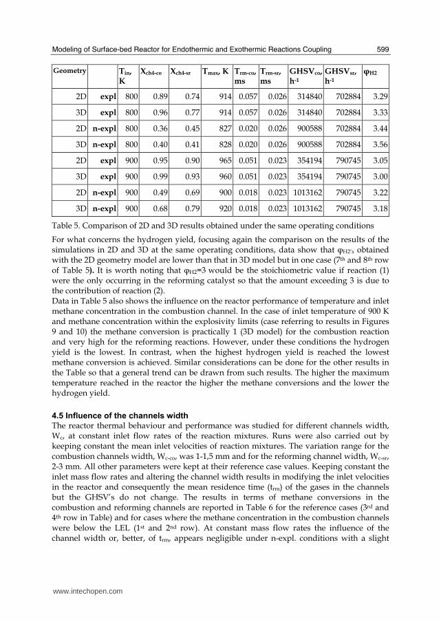
Modeling of Surface-bed Reactor for Endothermic and Exothermic Reactions Coupling
599
Geometry Tin K
Xch4-co Xch4-sr Tmax K Trm-co ms
Trm-sr ms
GHSVco h-1
GHSVsr h-1
φH2
2D expl 800 089 074 914 0057 0026 314840 702884 329
3D expl 800 096 077 914 0057 0026 314840 702884 333
2D n-expl 800 036 045 827 0020 0026 900588 702884 344
3D n-expl 800 040 041 828 0020 0026 900588 702884 356
2D expl 900 095 090 965 0051 0023 354194 790745 305
3D expl 900 099 093 960 0051 0023 354194 790745 300
2D n-expl 900 049 069 900 0018 0023 1013162 790745 322
3D n-expl 900 068 079 920 0018 0023 1013162 790745 318
Table 5 Comparison of 2D and 3D results obtained under the same operating conditions
For what concerns the hydrogen yield focusing again the comparison on the results of the simulations in 2D and 3D at the same operating conditions data show that φH2rsquos obtained with the 2D geometry model are lower than that in 3D model but in one case (7th and 8th row of Table 5) It is worth noting that φH2=3 would be the stoichiometric value if reaction (1) were the only occurring in the reforming catalyst so that the amount exceeding 3 is due to the contribution of reaction (2) Data in Table 5 also shows the influence on the reactor performance of temperature and inlet methane concentration in the combustion channel In the case of inlet temperature of 900 K and methane concentration within the explosivity limits (case referring to results in Figures 9 and 10) the methane conversion is practically 1 (3D model) for the combustion reaction and very high for the reforming reactions However under these conditions the hydrogen yield is the lowest In contrast when the highest hydrogen yield is reached the lowest methane conversion is achieved Similar considerations can be done for the other results in the Table so that a general trend can be drawn from such results The higher the maximum temperature reached in the reactor the higher the methane conversions and the lower the hydrogen yield
45 Influence of the channels width
The reactor thermal behaviour and performance was studied for different channels width Wc at constant inlet flow rates of the reaction mixtures Runs were also carried out by keeping constant the mean inlet velocities of reaction mixtures The variation range for the combustion channels width Wc-co was 1-15 mm and for the reforming channel width Wc-sr 2-3 mm All other parameters were kept at their reference case values Keeping constant the inlet mass flow rates and altering the channel width results in modifying the inlet velocities in the reactor and consequently the mean residence time (trm) of the gases in the channels but the GHSVrsquos do not change The results in terms of methane conversions in the combustion and reforming channels are reported in Table 6 for the reference cases (3rd and 4th row in Table) and for cases where the methane concentration in the combustion channels were below the LEL (1st and 2nd row) At constant mass flow rates the influence of the channel width or better of trm appears negligible under n-expl conditions with a slight
wwwintechopencom
Recent Advances in Modelling and Simulation
600
prevalence of the reactor with narrower channels and weak under expl conditions with in contrast better performance for the reactor with wider channels Therefore it is not possible to draw conclusions
Wc-sr mm
Tin K
Xch4 -
co Xch4-sr
Tmax K
trm-co ms
trm-sr ms
GHSVco h-1
GHSVsr h-1
2 n-expl 800 036 045 827 0020 0026 900588 702884
3 n-expl 800 034 044 819 0030 0038 900588 702884
2 expl 800 089 074 914 0057 0026 314840 702884
3 expl 800 092 081 940 0086 0038 314840 702884
Vcost- 3 n-expl 800 022 033 800 0020 0026 1350882 1054327
Table 6 Comparison between reactor performance as a function of channel width
Unlike the previous case where inlet flow rates were kept constant an increase in channel width keeping the mean gas velocity and the value of trm constants affects significantly the outlet conversions In this case the amount of reactants flowing through the reactor per unit catalyst volume and then GHSV increases (compare 1st and 5th rows in Table 5) Increasing channel widths from their reference case value (Wc-sr = 2 mm and Wc-co= 1) at constant gas inlet velocity leads to methane conversion reduction because a) the catalyst amount becomes insufficient for the amount of reactants fed in the reactor and b) the external mass transfer resistances play a stronger role The overall reaction heat fluxes remain the same as channel width increases leaving a similar amount of sensible heat to be used for heating up larger amounts of reactants This results in lower temperatures along the reactor
46 Influence of catalyst thickness
The influence of catalyst thickness c on the reactor behaviour was studied by keeping constant the reactants mass flow rates The reactor operation was simulated for three values of catalyst thickness ie 200 100 and 50 microm while keeping all the other parameters at their reference case values but for what concerns the inlet methane concentration in the combustion channel that was at non explosive level This with respect to the reference case corresponds to decreasing GHSV of factors 2 and 4 respectively Changes in the catalyst thickness influence considerably both thermal behaviour and outlet conversions As above the comparison is made through the methane conversions achieved in the two cases both in the steam reforming and in the combustion channels The results are reported in Table 7 It is evident that the loss of performance due to a decrease of 50 of c from 200 to 100 μm is almost negligible This is mainly due to the conservative parameters used for defining the catalyst layer characteristics (ie mean pore radius and tortuosity) that results in a very impervious path for diffusing gases However when c is further decreased methane conversion both in the combustion and in the reforming section significantly decrease The hydrogen yield does not change too much within the limits of the three cases analyzed
wwwintechopencom
Modeling of Surface-bed Reactor for Endothermic and Exothermic Reactions Coupling
601
δc μm
Tin K Xch4 -co Xch4-sr Tmax Ktrm-co ms
trm-sr ms
GHSVco h-1
GHSVsr h-1
φH2
200 n-expl 800 036 045 827 0020 0026 900588 702884 344
100 n-expl 800 035 045 827 0020 0026 1801176 1405768 344
50 n-expl 800 027 038 800 0020 0026 3602352 2811536 342
Table 7 Comparison between reactor performance as a function of catalyst thickness
5 Discussion
As seen in the previous section (4) there are several operating parameters that influence the performances of the system They are typical of reacting systems and can be summarized as GHSVrsquos tmrrsquos and inlet gas temperatures The particularity of the present case is the simultaneous occurrence of two coupled reactions one exothermic and the other endothermic in which the extent of the second depends on the extent (heat produced) of the first and the effectiveness of the heat transferred In addition the coupling of the two reactions does not exclude to have for each set of values of the mentioned parameters pertaining to one reaction several sets of parameters for the other reaction This makes the system quite complex and difficult to analyze However some general considerations can be drawn
Figure 11 Methane conversions in the combustion and reforming sides of the reactor as a function of GHSV for various operating conditions available in Table 6 and 7
The first is that as expected GHVS plays a key role in determining the reactor performances although this is supported by only a part of the data For instance data in Table 7 pertaining to simulations of the influence of such a parameter carried out by changing GHSV in the same way for both sections of the reacting system shows a clear effect of GHSV the reactor
0 1000000 2000000 3000000 4000000
GHSV h-1
02
04
06
08
1
XC
H4
-co a
nd
XC
H4
-sr -
data from Table 7 comb side
data from Table 7 refor side
data from Table 6 comb side
data from Table 6 refor side
wwwintechopencom
Recent Advances in Modelling and Simulation
602
performance decreases as GHSV increases on both sides of the reactor Such an influence does not appear strong the conversion change being about 20 against GHSV variations of a factor 4 (Figure 11) The influence of GHSV is more evident from data in Table 6 pertaining to simulations of the influence of tmr In fact also in this case a clear trend appears and the influence even though in the same direction of the previous case appears much stronger since with respect to a GHSV change of about 20 the methane conversion varies by a factor 4 (Figure 11) Such a strong influence is due to the combined effect of tmr especially on the combustion side of the reactor (cfr Table 6) Instead for data in Table 5 pertaining to simulations of the reliability of 2D and 3D models and the effect of gas inlet temperature it is not possible to highlight a clear influence The comparison between the results obtained with the 2D and 3D models under the same operating conditions have evidenced differences in the performance of the reactor not large but significant When we move from 2D to 3D models such differences result in an increase from 5 to 20 of both Xch4-co and Xch4-sr which reflects a different thermal behavior of the reacting system and influence also the hydrogen yield It is worth noting that the computation time required in the two cases is very different Specifically using an HP xw8400workstation equipped with 2 Xeon processors and 4 GB of RAM a 2D simulation takes on the average about 20 minutes with respect to 50-60 hours necessary in the 3D case It is impossible by now to establish which is the more correct or the more reliable In particular it should be assessed if 2D simulations are suitable for purpose of reactor design and experimental data interpretation The answer should come from the comparison of the results of such simulations with experimental data obtained with a real reactor geometrically comparable operated under conditions as much as similar to those fixed for the simulations This represents argument for coming work of the authors Further interesting aspects to be studied are the simulation of unsteady-state conditions and specifically of the system start-up and of the system response to small changes in the gas feeding flow rates and temperatures
6 Conclusions
Methane steam reforming coupled with methane catalytic combustion by means of indirect heat transfer in a surface-bed catalytic reactor was studied by 2D and 3D models The reactor consists of a central reforming channel and two lateral combustion channels A reference case for what concerns operating conditions and reactor geometry was chosen and its simulation was carried out Changes of reactor performance as consequence of operating parameters and reactor geometry variations were analyzed with respect to the reference case The simulation showed that suitable amount of fuel and adequate catalyst activity in the combustion channel can provide enough heat to simultaneously heat up the reaction mixture and drive the endothermic process The proximity between the heat source and the heat sink increases the efficiency of heat transfer resulting in transverse temperature gradients do not exceeding generally 07 K across the metallic wall and 20 K across the gas in the channel Decrease of transverse temperature differences and intraphase mass transfer resistances have the global effect of reducing the reactor dimension and the catalyst amount The influence of channels width and catalyst layer thickness on reactor behaviour was also studied At constant inlet flow rates changes of channel width in the range 1ndash2 mm do not introduce significant differences in the reactor performance Rather small differences in the
wwwintechopencom
Modeling of Surface-bed Reactor for Endothermic and Exothermic Reactions Coupling
603
catalyst axial temperature profiles and outlet methane conversions are observed In contrast altering the channel width at constant inlet velocities has strong influence Larger channel width results in lower conversion and smoother axial temperature profiles Intraphase resistances are present even for catalyst thickness of micrometers for both reforming and combustion processes Increasing GHSV that is the inlet flow ratecatalyst volume ratio leads to lower outlet conversions Due to different effect of catalyst layer thickness on reforming and combustion channels there are significant changes in the reactor temperature profile Results indicate that steam reforming of methane in a surface-bed reactor is feasible provided that mass flow rates channels width catalyst loadings and thickness are properly designed
7 Notation
cp specific heat J(mol K) c concentration molm3 Deff effective diffusion coefficient m2s D molecular diffusion coefficient m2s GHSV gas hourly space velocity h-1 k thermal conductivity W(m K) or reaction rate constant Ke equilibrium constant M molecular weight kgmol LEL lower explosivity limit vol
unit vector perpendicular to the flux surface
N molar flux at the boundary mol(m2 s) p partial pressure bar P total pressure bar q thermal flux at the boundary J(m2 s) r reaction rate various dimensions (see eqs 1rsquo 2rsquo and 3rsquo) Rp catalyst pore radius nm STP standard temperature and pressure (298 K and 101 103 Pa) t time s T temperature K ts transverse surface ux Velocity component on the x coordinate
velocity vector
v normal component of velocity at the channel ingress x axial coordinate m X conversion y transverse coordinate m Wc distance between the reactor plates m z vertical coordinate m Greek letters ΔH0r heat of reaction at reference state conditions KJmol c catalyst thickness μm catalyst porosity φ atomic diffusion volume or chemical reaction yield
wwwintechopencom
Recent Advances in Modelling and Simulation
604
θ stoichiometric coefficient ρ density kgm3 τ catalyst tortuosity
Subscripts and superscripts cat catalyst co combustion CH4 methane H2 hydrogen in inlet i chemical species j channel k reaction l phase rm mean residence s metal sheet sr steam reforming 0 channel ingress 1 reforming reaction 2 water gas shift reaction 3 combustion reaction
8 Acknowledgements
The authors gratefully acknowledge the financial support of MIUR under grant PRIN ndeg 2006094333004
9 References
Akers WW amp Camp DP (1955) Kinetics of the methanendashsteam reaction AIChE Journal Vol 1 471ndash475 ISSN0001-1541
Allen DW Gerhard ER amp Likins Jr MR (1975) Kinetics of the MethanendashSteam Reaction Ind Eng Chem Proc Des Dev Vol 14 No 3 256-259 ISSN0196-4305
Aparicio L (1997) Transient Isotopic Studies and Microkinetic Modeling of Methane Reforming over Nickel Catalysts Journal of Catal Vol 165 No 2 262-274 ISSN 0021-9517
Avci AK Trimm DL amp İlsen Oumlnsan Z (2001) Heterogeneous reactor modeling for simulation of catalytic oxidation and steam reforming of methane Chem Eng Sci Vol 56 No 2 641-649 ISSN0009-2509
Bridger GW (1980) The steam reforming of hydrocarbons Catalysis Vol 3 39-69 ISSN0140-0568
Cao C Wang Y amp Rozmiarek RT (2005) Heterogeneous reactor model for steam reforming of methane in a microchannel reactor with microstructured catalysts Catal Today Vol 110 No 1-2 92ndash97 ISSN 0920-5861
Craciun R Shereck B amp Gorte RJ (1998) Kinetic studies of methane steam reforming on ceria-supported Pd Catal Lett Vol 51 No 3ndash4 149-153 ISSN 1011-372x
wwwintechopencom
Modeling of Surface-bed Reactor for Endothermic and Exothermic Reactions Coupling
605
Crowl DA amp Louvar JF (2002) Chemical Process Safety fundamentals with applications 2nd ed Prentice Hall PTR Upper Saddle River NJ USA ISBN 0-13mdash018176-5
De Deken J C Devos E F amp Froment G F (1982) Steam reforming of natural gas Intrinsic kinetics diffusional influences and reactor design ACS Symposium Series 196 181ndash197 ISSN0097-6156
Ehrfeld W amp Hessel V Lowe H (2000) Microreactor Wiley-VCH Verlag GmbH D-69469 ISBN Weinheim Germany
Gosiewski K (2001) Simulations of non-stationary reactors for catalytic conversion of methane to synthesis gas Chem Eng Sci Vol 56 No 4 1501-1510 ISSN
Groppi G Belloli A Tronconi E Forzatti P (1995) A comparison of lumped and distributed models of monolith catalytic combustors Chem Eng Sci Vol 50 No 17 2705ndash2715 ISSN0009-2509
Holladay JD Wang Y amp Jones E (2004) Review of Developments in Portable Hydrogen Production Using Microreactor Technology Chem Rev Vol 104 No 10 4767-4790 ISSN 0009-2665
Hou K amp Hughes R (2001) The kinetics of methane steam reforming over a Ni-Al2O3 catalyst Chem Eng Journal Vol 82 No 1-3 311-328 ISSN 1385-8947
Jamal Y amp Wyszynski M L (1994) On-board generation of hydrogen-rich gaseous fuels a review Int J of Hydrogen Energy Vol 19 No 7 557-572 ISSN 0360-3199
Jensen KF (2001) Microreaction engineering is small better Chem Eng Sci Vol 56 No 2 293-303 ISSN0009-2509
Kolios G Gritsch A Glo1ckler B amp Sorescu G (2004) Novel Reactor Concepts for Thermally Efficient Methane Steam Reforming Modeling and Simulation Ind Eng Chem Res Vol 43 No 16 4796-4808 ISSN0888-5885
Kruger P Blakeley J amp Leaver J (2003) Potential in New Zealand for use of hydrogen as a transportation fuel Int J of Hydrogen Energy Vol 28 No 8 795ndash802 ISSN 0360-3199
Kvamsdal HM Svendsen HF Hertzberg T amp Olsvik O (1999) Dynamic simulation and optimization of a catalytic steam reformer Chem Eng Sci Vol 54 No 13-14 2697-2706 ISSN0009-2509
Lerer M Duic N Alves LM amp Carvalho MG (2006) H2 RES energy planning tool for increasing the penetration of renewable energy sources in island energy supply In New and Renewable Technologies for Sustanaible Development MG Carvalho and NH Afgan (Ed s) 15-30 World Scientific ISBN 10 981-270-505-8 Singapore
Lerou JJ amp Ng KM (1996) Chemical reaction engineering A multiscale approach to a multiobjective task Chem Eng Sci Vol 51 No 10 1595-1614 ISSN0009-2509
Lincoln SF (2006) Challenged Earth ch7 Imperial College Press ISBN 1-86094-526-0 London
Loffler D G Faz C F Sokolovskii V amp Iglesia E (2002) Catalytic separator plate reactor and method of catalytic reforming of fuel to Hydrogen PCT Int Appl WO 0228769 A2
Luna C amp Becerra AM (1997) Kinetics of methane steam reforming on a Ni on alumina-titania catalyst React Kinet Catal Lett Vol 61 No 2 369-374 ISSN 0133-1736
Marschner F Renner HJ amp Boll W (2005) Electronic Encyclopedia Release 2005 7th ed in Ullmannrsquos Encyclopedia of Industrial Chemistry M Bohnet et al (Eds) Vol a12 John Wiley amp Sons ISBN-13 978-3-527-30385-4
wwwintechopencom
Recent Advances in Modelling and Simulation
606
Moore R B amp Raman V (1998) Hydrogen infrastructure for fuel cell transportation Int J of Hydrogen Energy Vol 23 No 7 617-620 ISSN 0360-3199
Perry RH amp Green DW (1999) Perrys Chemical Engineers Handbook (7th Ed) McGraw-Hill ISBN 0-07-049841-5
Robbins F A Zhu H amp Jackson GS (2003) Transient modeling of combined catalytic combustionCH4 steam reformng Catal Today Vol 83 No 1-4 141ndash156 ISSN 0920-5861
Rostrup-Nielsen JR Christiansen LJ amp BakHansen JH (1988) Activity of steam reforming catalysts Role and assessment Appl Catal Vol 43 No 2 287-303 ISSN0166-9834
Rostrup-Nielsen JR (1995) Innovation and the catalytic process industry - the science and challenge Chem Eng Sci Vol 50 No 24 4061-4071 ISSN0009-2509
Rostrup-Nielsen JR Dybkjaer I amp Coulthard GRG (2001) Topical Conf Proc AIChE Spring National Meeting Houston TX April Paper No 1
Rostrup-Nielsen JR (2004) Fuels and Energy for the Future The Role of Catalysis Catal Rev - Science and Engineering Vol 46 No 3ndash4 247-270 ISSN0161-4940
Schubert K Brandner J Fichtner M Linder G Schyhulla U amp Wenka A (2001) Microstructure devices for applications in thermal and chemical process engineering Microscale Thermophys Eng Vol 5 No 1 17-39 ISSN1089-3954
Tronconi E amp Groppi G (2000) A study on the thermal behavior of structured plate-type catalysts with metallic supports for gassolid exothermic reactions Chem Eng Sci Vol 55 Issue 24 December 6021-6036 ISSN0009-2509
Wang Y Johnson BR Cao C Chin Y Rozmiarek RT Gao Y Tonkovich AL (2005) Engineered catalysts for microchannel reactor applications In Microreactor Technology and Process Intensification Y Wang J Holladay (Eds) 65-73 ACS Symposium Series Vol 914 ISBN-13 9780841239234
Xu J amp Froment GF (1989a) Methane steam reforming II Diffusional limitations and reactor simulation AIChE Journal Vol 35 No 1 97-103 ISSN0001-1541
Xu J amp Froment GF (1989b) Methane steam reforming methanation and water-gas shift I Intrinsic kinetics AIChE Journal Vol 35 No 1 88-96 ISSN0001-1541
Zanfir M amp Gavriilidis A (2003) Catalytic Combustion Assisted Methane Steam Reforming Chem Eng Sci Vol 58 No 17 3947ndash 3960 ISSN0009-2509
wwwintechopencom
Modelling and SimulationEdited by Giuseppe Petrone and Giuliano Cammarata
ISBN 978-3-902613-25-7Hard cover 688 pagesPublisher I-Tech Education and PublishingPublished online 01 June 2008Published in print edition June 2008
InTech EuropeUniversity Campus STeP Ri Slavka Krautzeka 83A 51000 Rijeka Croatia Phone +385 (51) 770 447 Fax +385 (51) 686 166wwwintechopencom
InTech ChinaUnit 405 Office Block Hotel Equatorial Shanghai No65 Yan An Road (West) Shanghai 200040 China
Phone +86-21-62489820 Fax +86-21-62489821
This book collects original and innovative research studies concerning modeling and simulation of physicalsystems in a very wide range of applications encompassing micro-electro-mechanical systems measurementinstrumentations catalytic reactors biomechanical applications biological and chemical sensorsmagnetosensitive materials silicon photonic devices electronic devices optical fibers electro-microfluidicsystems composite materials fuel cells indoor air-conditioning systems active magnetic levitation systemsand more Some of the most recent numerical techniques as well as some of the software among the mostaccurate and sophisticated in treating complex systems are applied in order to exhaustively contribute inknowledge advances
How to referenceIn order to correctly reference this scholarly work feel free to copy and paste the following
Salvatore Vaccaro and Paolo Ciambelli (2008) Modeling of Surface-bed Reactor for Endothermic andExothermic Reactions Coupling Modelling and Simulation Giuseppe Petrone and Giuliano Cammarata (Ed)ISBN 978-3-902613-25-7 InTech Available fromhttpwwwintechopencombooksmodelling_and_simulationmodeling_of_surface-bed_reactor_for_endothermic_and_exothermic_reactions_coupling
copy 2008 The Author(s) Licensee IntechOpen This chapter is distributedunder the terms of the Creative Commons Attribution-NonCommercial-ShareAlike-30 License which permits use distribution and reproduction fornon-commercial purposes provided the original is properly cited andderivative works building on this content are distributed under the samelicense
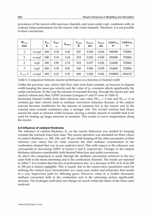
Recent Advances in Modelling and Simulation
600
prevalence of the reactor with narrower channels and weak under expl conditions with in contrast better performance for the reactor with wider channels Therefore it is not possible to draw conclusions
Wc-sr mm
Tin K
Xch4 -
co Xch4-sr
Tmax K
trm-co ms
trm-sr ms
GHSVco h-1
GHSVsr h-1
2 n-expl 800 036 045 827 0020 0026 900588 702884
3 n-expl 800 034 044 819 0030 0038 900588 702884
2 expl 800 089 074 914 0057 0026 314840 702884
3 expl 800 092 081 940 0086 0038 314840 702884
Vcost- 3 n-expl 800 022 033 800 0020 0026 1350882 1054327
Table 6 Comparison between reactor performance as a function of channel width
Unlike the previous case where inlet flow rates were kept constant an increase in channel width keeping the mean gas velocity and the value of trm constants affects significantly the outlet conversions In this case the amount of reactants flowing through the reactor per unit catalyst volume and then GHSV increases (compare 1st and 5th rows in Table 5) Increasing channel widths from their reference case value (Wc-sr = 2 mm and Wc-co= 1) at constant gas inlet velocity leads to methane conversion reduction because a) the catalyst amount becomes insufficient for the amount of reactants fed in the reactor and b) the external mass transfer resistances play a stronger role The overall reaction heat fluxes remain the same as channel width increases leaving a similar amount of sensible heat to be used for heating up larger amounts of reactants This results in lower temperatures along the reactor
46 Influence of catalyst thickness
The influence of catalyst thickness c on the reactor behaviour was studied by keeping constant the reactants mass flow rates The reactor operation was simulated for three values of catalyst thickness ie 200 100 and 50 microm while keeping all the other parameters at their reference case values but for what concerns the inlet methane concentration in the combustion channel that was at non explosive level This with respect to the reference case corresponds to decreasing GHSV of factors 2 and 4 respectively Changes in the catalyst thickness influence considerably both thermal behaviour and outlet conversions As above the comparison is made through the methane conversions achieved in the two cases both in the steam reforming and in the combustion channels The results are reported in Table 7 It is evident that the loss of performance due to a decrease of 50 of c from 200 to 100 μm is almost negligible This is mainly due to the conservative parameters used for defining the catalyst layer characteristics (ie mean pore radius and tortuosity) that results in a very impervious path for diffusing gases However when c is further decreased methane conversion both in the combustion and in the reforming section significantly decrease The hydrogen yield does not change too much within the limits of the three cases analyzed
wwwintechopencom
Modeling of Surface-bed Reactor for Endothermic and Exothermic Reactions Coupling
601
δc μm
Tin K Xch4 -co Xch4-sr Tmax Ktrm-co ms
trm-sr ms
GHSVco h-1
GHSVsr h-1
φH2
200 n-expl 800 036 045 827 0020 0026 900588 702884 344
100 n-expl 800 035 045 827 0020 0026 1801176 1405768 344
50 n-expl 800 027 038 800 0020 0026 3602352 2811536 342
Table 7 Comparison between reactor performance as a function of catalyst thickness
5 Discussion
As seen in the previous section (4) there are several operating parameters that influence the performances of the system They are typical of reacting systems and can be summarized as GHSVrsquos tmrrsquos and inlet gas temperatures The particularity of the present case is the simultaneous occurrence of two coupled reactions one exothermic and the other endothermic in which the extent of the second depends on the extent (heat produced) of the first and the effectiveness of the heat transferred In addition the coupling of the two reactions does not exclude to have for each set of values of the mentioned parameters pertaining to one reaction several sets of parameters for the other reaction This makes the system quite complex and difficult to analyze However some general considerations can be drawn
Figure 11 Methane conversions in the combustion and reforming sides of the reactor as a function of GHSV for various operating conditions available in Table 6 and 7
The first is that as expected GHVS plays a key role in determining the reactor performances although this is supported by only a part of the data For instance data in Table 7 pertaining to simulations of the influence of such a parameter carried out by changing GHSV in the same way for both sections of the reacting system shows a clear effect of GHSV the reactor
0 1000000 2000000 3000000 4000000
GHSV h-1
02
04
06
08
1
XC
H4
-co a
nd
XC
H4
-sr -
data from Table 7 comb side
data from Table 7 refor side
data from Table 6 comb side
data from Table 6 refor side
wwwintechopencom
Recent Advances in Modelling and Simulation
602
performance decreases as GHSV increases on both sides of the reactor Such an influence does not appear strong the conversion change being about 20 against GHSV variations of a factor 4 (Figure 11) The influence of GHSV is more evident from data in Table 6 pertaining to simulations of the influence of tmr In fact also in this case a clear trend appears and the influence even though in the same direction of the previous case appears much stronger since with respect to a GHSV change of about 20 the methane conversion varies by a factor 4 (Figure 11) Such a strong influence is due to the combined effect of tmr especially on the combustion side of the reactor (cfr Table 6) Instead for data in Table 5 pertaining to simulations of the reliability of 2D and 3D models and the effect of gas inlet temperature it is not possible to highlight a clear influence The comparison between the results obtained with the 2D and 3D models under the same operating conditions have evidenced differences in the performance of the reactor not large but significant When we move from 2D to 3D models such differences result in an increase from 5 to 20 of both Xch4-co and Xch4-sr which reflects a different thermal behavior of the reacting system and influence also the hydrogen yield It is worth noting that the computation time required in the two cases is very different Specifically using an HP xw8400workstation equipped with 2 Xeon processors and 4 GB of RAM a 2D simulation takes on the average about 20 minutes with respect to 50-60 hours necessary in the 3D case It is impossible by now to establish which is the more correct or the more reliable In particular it should be assessed if 2D simulations are suitable for purpose of reactor design and experimental data interpretation The answer should come from the comparison of the results of such simulations with experimental data obtained with a real reactor geometrically comparable operated under conditions as much as similar to those fixed for the simulations This represents argument for coming work of the authors Further interesting aspects to be studied are the simulation of unsteady-state conditions and specifically of the system start-up and of the system response to small changes in the gas feeding flow rates and temperatures
6 Conclusions
Methane steam reforming coupled with methane catalytic combustion by means of indirect heat transfer in a surface-bed catalytic reactor was studied by 2D and 3D models The reactor consists of a central reforming channel and two lateral combustion channels A reference case for what concerns operating conditions and reactor geometry was chosen and its simulation was carried out Changes of reactor performance as consequence of operating parameters and reactor geometry variations were analyzed with respect to the reference case The simulation showed that suitable amount of fuel and adequate catalyst activity in the combustion channel can provide enough heat to simultaneously heat up the reaction mixture and drive the endothermic process The proximity between the heat source and the heat sink increases the efficiency of heat transfer resulting in transverse temperature gradients do not exceeding generally 07 K across the metallic wall and 20 K across the gas in the channel Decrease of transverse temperature differences and intraphase mass transfer resistances have the global effect of reducing the reactor dimension and the catalyst amount The influence of channels width and catalyst layer thickness on reactor behaviour was also studied At constant inlet flow rates changes of channel width in the range 1ndash2 mm do not introduce significant differences in the reactor performance Rather small differences in the
wwwintechopencom
Modeling of Surface-bed Reactor for Endothermic and Exothermic Reactions Coupling
603
catalyst axial temperature profiles and outlet methane conversions are observed In contrast altering the channel width at constant inlet velocities has strong influence Larger channel width results in lower conversion and smoother axial temperature profiles Intraphase resistances are present even for catalyst thickness of micrometers for both reforming and combustion processes Increasing GHSV that is the inlet flow ratecatalyst volume ratio leads to lower outlet conversions Due to different effect of catalyst layer thickness on reforming and combustion channels there are significant changes in the reactor temperature profile Results indicate that steam reforming of methane in a surface-bed reactor is feasible provided that mass flow rates channels width catalyst loadings and thickness are properly designed
7 Notation
cp specific heat J(mol K) c concentration molm3 Deff effective diffusion coefficient m2s D molecular diffusion coefficient m2s GHSV gas hourly space velocity h-1 k thermal conductivity W(m K) or reaction rate constant Ke equilibrium constant M molecular weight kgmol LEL lower explosivity limit vol
unit vector perpendicular to the flux surface
N molar flux at the boundary mol(m2 s) p partial pressure bar P total pressure bar q thermal flux at the boundary J(m2 s) r reaction rate various dimensions (see eqs 1rsquo 2rsquo and 3rsquo) Rp catalyst pore radius nm STP standard temperature and pressure (298 K and 101 103 Pa) t time s T temperature K ts transverse surface ux Velocity component on the x coordinate
velocity vector
v normal component of velocity at the channel ingress x axial coordinate m X conversion y transverse coordinate m Wc distance between the reactor plates m z vertical coordinate m Greek letters ΔH0r heat of reaction at reference state conditions KJmol c catalyst thickness μm catalyst porosity φ atomic diffusion volume or chemical reaction yield
wwwintechopencom
Recent Advances in Modelling and Simulation
604
θ stoichiometric coefficient ρ density kgm3 τ catalyst tortuosity
Subscripts and superscripts cat catalyst co combustion CH4 methane H2 hydrogen in inlet i chemical species j channel k reaction l phase rm mean residence s metal sheet sr steam reforming 0 channel ingress 1 reforming reaction 2 water gas shift reaction 3 combustion reaction
8 Acknowledgements
The authors gratefully acknowledge the financial support of MIUR under grant PRIN ndeg 2006094333004
9 References
Akers WW amp Camp DP (1955) Kinetics of the methanendashsteam reaction AIChE Journal Vol 1 471ndash475 ISSN0001-1541
Allen DW Gerhard ER amp Likins Jr MR (1975) Kinetics of the MethanendashSteam Reaction Ind Eng Chem Proc Des Dev Vol 14 No 3 256-259 ISSN0196-4305
Aparicio L (1997) Transient Isotopic Studies and Microkinetic Modeling of Methane Reforming over Nickel Catalysts Journal of Catal Vol 165 No 2 262-274 ISSN 0021-9517
Avci AK Trimm DL amp İlsen Oumlnsan Z (2001) Heterogeneous reactor modeling for simulation of catalytic oxidation and steam reforming of methane Chem Eng Sci Vol 56 No 2 641-649 ISSN0009-2509
Bridger GW (1980) The steam reforming of hydrocarbons Catalysis Vol 3 39-69 ISSN0140-0568
Cao C Wang Y amp Rozmiarek RT (2005) Heterogeneous reactor model for steam reforming of methane in a microchannel reactor with microstructured catalysts Catal Today Vol 110 No 1-2 92ndash97 ISSN 0920-5861
Craciun R Shereck B amp Gorte RJ (1998) Kinetic studies of methane steam reforming on ceria-supported Pd Catal Lett Vol 51 No 3ndash4 149-153 ISSN 1011-372x
wwwintechopencom
Modeling of Surface-bed Reactor for Endothermic and Exothermic Reactions Coupling
605
Crowl DA amp Louvar JF (2002) Chemical Process Safety fundamentals with applications 2nd ed Prentice Hall PTR Upper Saddle River NJ USA ISBN 0-13mdash018176-5
De Deken J C Devos E F amp Froment G F (1982) Steam reforming of natural gas Intrinsic kinetics diffusional influences and reactor design ACS Symposium Series 196 181ndash197 ISSN0097-6156
Ehrfeld W amp Hessel V Lowe H (2000) Microreactor Wiley-VCH Verlag GmbH D-69469 ISBN Weinheim Germany
Gosiewski K (2001) Simulations of non-stationary reactors for catalytic conversion of methane to synthesis gas Chem Eng Sci Vol 56 No 4 1501-1510 ISSN
Groppi G Belloli A Tronconi E Forzatti P (1995) A comparison of lumped and distributed models of monolith catalytic combustors Chem Eng Sci Vol 50 No 17 2705ndash2715 ISSN0009-2509
Holladay JD Wang Y amp Jones E (2004) Review of Developments in Portable Hydrogen Production Using Microreactor Technology Chem Rev Vol 104 No 10 4767-4790 ISSN 0009-2665
Hou K amp Hughes R (2001) The kinetics of methane steam reforming over a Ni-Al2O3 catalyst Chem Eng Journal Vol 82 No 1-3 311-328 ISSN 1385-8947
Jamal Y amp Wyszynski M L (1994) On-board generation of hydrogen-rich gaseous fuels a review Int J of Hydrogen Energy Vol 19 No 7 557-572 ISSN 0360-3199
Jensen KF (2001) Microreaction engineering is small better Chem Eng Sci Vol 56 No 2 293-303 ISSN0009-2509
Kolios G Gritsch A Glo1ckler B amp Sorescu G (2004) Novel Reactor Concepts for Thermally Efficient Methane Steam Reforming Modeling and Simulation Ind Eng Chem Res Vol 43 No 16 4796-4808 ISSN0888-5885
Kruger P Blakeley J amp Leaver J (2003) Potential in New Zealand for use of hydrogen as a transportation fuel Int J of Hydrogen Energy Vol 28 No 8 795ndash802 ISSN 0360-3199
Kvamsdal HM Svendsen HF Hertzberg T amp Olsvik O (1999) Dynamic simulation and optimization of a catalytic steam reformer Chem Eng Sci Vol 54 No 13-14 2697-2706 ISSN0009-2509
Lerer M Duic N Alves LM amp Carvalho MG (2006) H2 RES energy planning tool for increasing the penetration of renewable energy sources in island energy supply In New and Renewable Technologies for Sustanaible Development MG Carvalho and NH Afgan (Ed s) 15-30 World Scientific ISBN 10 981-270-505-8 Singapore
Lerou JJ amp Ng KM (1996) Chemical reaction engineering A multiscale approach to a multiobjective task Chem Eng Sci Vol 51 No 10 1595-1614 ISSN0009-2509
Lincoln SF (2006) Challenged Earth ch7 Imperial College Press ISBN 1-86094-526-0 London
Loffler D G Faz C F Sokolovskii V amp Iglesia E (2002) Catalytic separator plate reactor and method of catalytic reforming of fuel to Hydrogen PCT Int Appl WO 0228769 A2
Luna C amp Becerra AM (1997) Kinetics of methane steam reforming on a Ni on alumina-titania catalyst React Kinet Catal Lett Vol 61 No 2 369-374 ISSN 0133-1736
Marschner F Renner HJ amp Boll W (2005) Electronic Encyclopedia Release 2005 7th ed in Ullmannrsquos Encyclopedia of Industrial Chemistry M Bohnet et al (Eds) Vol a12 John Wiley amp Sons ISBN-13 978-3-527-30385-4
wwwintechopencom
Recent Advances in Modelling and Simulation
606
Moore R B amp Raman V (1998) Hydrogen infrastructure for fuel cell transportation Int J of Hydrogen Energy Vol 23 No 7 617-620 ISSN 0360-3199
Perry RH amp Green DW (1999) Perrys Chemical Engineers Handbook (7th Ed) McGraw-Hill ISBN 0-07-049841-5
Robbins F A Zhu H amp Jackson GS (2003) Transient modeling of combined catalytic combustionCH4 steam reformng Catal Today Vol 83 No 1-4 141ndash156 ISSN 0920-5861
Rostrup-Nielsen JR Christiansen LJ amp BakHansen JH (1988) Activity of steam reforming catalysts Role and assessment Appl Catal Vol 43 No 2 287-303 ISSN0166-9834
Rostrup-Nielsen JR (1995) Innovation and the catalytic process industry - the science and challenge Chem Eng Sci Vol 50 No 24 4061-4071 ISSN0009-2509
Rostrup-Nielsen JR Dybkjaer I amp Coulthard GRG (2001) Topical Conf Proc AIChE Spring National Meeting Houston TX April Paper No 1
Rostrup-Nielsen JR (2004) Fuels and Energy for the Future The Role of Catalysis Catal Rev - Science and Engineering Vol 46 No 3ndash4 247-270 ISSN0161-4940
Schubert K Brandner J Fichtner M Linder G Schyhulla U amp Wenka A (2001) Microstructure devices for applications in thermal and chemical process engineering Microscale Thermophys Eng Vol 5 No 1 17-39 ISSN1089-3954
Tronconi E amp Groppi G (2000) A study on the thermal behavior of structured plate-type catalysts with metallic supports for gassolid exothermic reactions Chem Eng Sci Vol 55 Issue 24 December 6021-6036 ISSN0009-2509
Wang Y Johnson BR Cao C Chin Y Rozmiarek RT Gao Y Tonkovich AL (2005) Engineered catalysts for microchannel reactor applications In Microreactor Technology and Process Intensification Y Wang J Holladay (Eds) 65-73 ACS Symposium Series Vol 914 ISBN-13 9780841239234
Xu J amp Froment GF (1989a) Methane steam reforming II Diffusional limitations and reactor simulation AIChE Journal Vol 35 No 1 97-103 ISSN0001-1541
Xu J amp Froment GF (1989b) Methane steam reforming methanation and water-gas shift I Intrinsic kinetics AIChE Journal Vol 35 No 1 88-96 ISSN0001-1541
Zanfir M amp Gavriilidis A (2003) Catalytic Combustion Assisted Methane Steam Reforming Chem Eng Sci Vol 58 No 17 3947ndash 3960 ISSN0009-2509
wwwintechopencom
Modelling and SimulationEdited by Giuseppe Petrone and Giuliano Cammarata
ISBN 978-3-902613-25-7Hard cover 688 pagesPublisher I-Tech Education and PublishingPublished online 01 June 2008Published in print edition June 2008
InTech EuropeUniversity Campus STeP Ri Slavka Krautzeka 83A 51000 Rijeka Croatia Phone +385 (51) 770 447 Fax +385 (51) 686 166wwwintechopencom
InTech ChinaUnit 405 Office Block Hotel Equatorial Shanghai No65 Yan An Road (West) Shanghai 200040 China
Phone +86-21-62489820 Fax +86-21-62489821
This book collects original and innovative research studies concerning modeling and simulation of physicalsystems in a very wide range of applications encompassing micro-electro-mechanical systems measurementinstrumentations catalytic reactors biomechanical applications biological and chemical sensorsmagnetosensitive materials silicon photonic devices electronic devices optical fibers electro-microfluidicsystems composite materials fuel cells indoor air-conditioning systems active magnetic levitation systemsand more Some of the most recent numerical techniques as well as some of the software among the mostaccurate and sophisticated in treating complex systems are applied in order to exhaustively contribute inknowledge advances
How to referenceIn order to correctly reference this scholarly work feel free to copy and paste the following
Salvatore Vaccaro and Paolo Ciambelli (2008) Modeling of Surface-bed Reactor for Endothermic andExothermic Reactions Coupling Modelling and Simulation Giuseppe Petrone and Giuliano Cammarata (Ed)ISBN 978-3-902613-25-7 InTech Available fromhttpwwwintechopencombooksmodelling_and_simulationmodeling_of_surface-bed_reactor_for_endothermic_and_exothermic_reactions_coupling
copy 2008 The Author(s) Licensee IntechOpen This chapter is distributedunder the terms of the Creative Commons Attribution-NonCommercial-ShareAlike-30 License which permits use distribution and reproduction fornon-commercial purposes provided the original is properly cited andderivative works building on this content are distributed under the samelicense
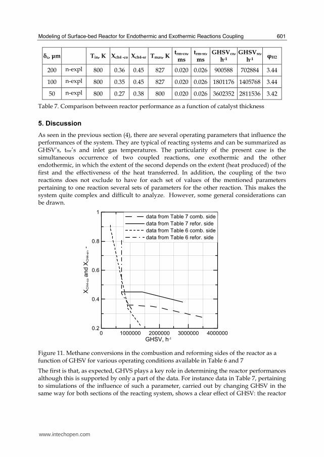
Modeling of Surface-bed Reactor for Endothermic and Exothermic Reactions Coupling
601
δc μm
Tin K Xch4 -co Xch4-sr Tmax Ktrm-co ms
trm-sr ms
GHSVco h-1
GHSVsr h-1
φH2
200 n-expl 800 036 045 827 0020 0026 900588 702884 344
100 n-expl 800 035 045 827 0020 0026 1801176 1405768 344
50 n-expl 800 027 038 800 0020 0026 3602352 2811536 342
Table 7 Comparison between reactor performance as a function of catalyst thickness
5 Discussion
As seen in the previous section (4) there are several operating parameters that influence the performances of the system They are typical of reacting systems and can be summarized as GHSVrsquos tmrrsquos and inlet gas temperatures The particularity of the present case is the simultaneous occurrence of two coupled reactions one exothermic and the other endothermic in which the extent of the second depends on the extent (heat produced) of the first and the effectiveness of the heat transferred In addition the coupling of the two reactions does not exclude to have for each set of values of the mentioned parameters pertaining to one reaction several sets of parameters for the other reaction This makes the system quite complex and difficult to analyze However some general considerations can be drawn
Figure 11 Methane conversions in the combustion and reforming sides of the reactor as a function of GHSV for various operating conditions available in Table 6 and 7
The first is that as expected GHVS plays a key role in determining the reactor performances although this is supported by only a part of the data For instance data in Table 7 pertaining to simulations of the influence of such a parameter carried out by changing GHSV in the same way for both sections of the reacting system shows a clear effect of GHSV the reactor
0 1000000 2000000 3000000 4000000
GHSV h-1
02
04
06
08
1
XC
H4
-co a
nd
XC
H4
-sr -
data from Table 7 comb side
data from Table 7 refor side
data from Table 6 comb side
data from Table 6 refor side
wwwintechopencom
Recent Advances in Modelling and Simulation
602
performance decreases as GHSV increases on both sides of the reactor Such an influence does not appear strong the conversion change being about 20 against GHSV variations of a factor 4 (Figure 11) The influence of GHSV is more evident from data in Table 6 pertaining to simulations of the influence of tmr In fact also in this case a clear trend appears and the influence even though in the same direction of the previous case appears much stronger since with respect to a GHSV change of about 20 the methane conversion varies by a factor 4 (Figure 11) Such a strong influence is due to the combined effect of tmr especially on the combustion side of the reactor (cfr Table 6) Instead for data in Table 5 pertaining to simulations of the reliability of 2D and 3D models and the effect of gas inlet temperature it is not possible to highlight a clear influence The comparison between the results obtained with the 2D and 3D models under the same operating conditions have evidenced differences in the performance of the reactor not large but significant When we move from 2D to 3D models such differences result in an increase from 5 to 20 of both Xch4-co and Xch4-sr which reflects a different thermal behavior of the reacting system and influence also the hydrogen yield It is worth noting that the computation time required in the two cases is very different Specifically using an HP xw8400workstation equipped with 2 Xeon processors and 4 GB of RAM a 2D simulation takes on the average about 20 minutes with respect to 50-60 hours necessary in the 3D case It is impossible by now to establish which is the more correct or the more reliable In particular it should be assessed if 2D simulations are suitable for purpose of reactor design and experimental data interpretation The answer should come from the comparison of the results of such simulations with experimental data obtained with a real reactor geometrically comparable operated under conditions as much as similar to those fixed for the simulations This represents argument for coming work of the authors Further interesting aspects to be studied are the simulation of unsteady-state conditions and specifically of the system start-up and of the system response to small changes in the gas feeding flow rates and temperatures
6 Conclusions
Methane steam reforming coupled with methane catalytic combustion by means of indirect heat transfer in a surface-bed catalytic reactor was studied by 2D and 3D models The reactor consists of a central reforming channel and two lateral combustion channels A reference case for what concerns operating conditions and reactor geometry was chosen and its simulation was carried out Changes of reactor performance as consequence of operating parameters and reactor geometry variations were analyzed with respect to the reference case The simulation showed that suitable amount of fuel and adequate catalyst activity in the combustion channel can provide enough heat to simultaneously heat up the reaction mixture and drive the endothermic process The proximity between the heat source and the heat sink increases the efficiency of heat transfer resulting in transverse temperature gradients do not exceeding generally 07 K across the metallic wall and 20 K across the gas in the channel Decrease of transverse temperature differences and intraphase mass transfer resistances have the global effect of reducing the reactor dimension and the catalyst amount The influence of channels width and catalyst layer thickness on reactor behaviour was also studied At constant inlet flow rates changes of channel width in the range 1ndash2 mm do not introduce significant differences in the reactor performance Rather small differences in the
wwwintechopencom
Modeling of Surface-bed Reactor for Endothermic and Exothermic Reactions Coupling
603
catalyst axial temperature profiles and outlet methane conversions are observed In contrast altering the channel width at constant inlet velocities has strong influence Larger channel width results in lower conversion and smoother axial temperature profiles Intraphase resistances are present even for catalyst thickness of micrometers for both reforming and combustion processes Increasing GHSV that is the inlet flow ratecatalyst volume ratio leads to lower outlet conversions Due to different effect of catalyst layer thickness on reforming and combustion channels there are significant changes in the reactor temperature profile Results indicate that steam reforming of methane in a surface-bed reactor is feasible provided that mass flow rates channels width catalyst loadings and thickness are properly designed
7 Notation
cp specific heat J(mol K) c concentration molm3 Deff effective diffusion coefficient m2s D molecular diffusion coefficient m2s GHSV gas hourly space velocity h-1 k thermal conductivity W(m K) or reaction rate constant Ke equilibrium constant M molecular weight kgmol LEL lower explosivity limit vol
unit vector perpendicular to the flux surface
N molar flux at the boundary mol(m2 s) p partial pressure bar P total pressure bar q thermal flux at the boundary J(m2 s) r reaction rate various dimensions (see eqs 1rsquo 2rsquo and 3rsquo) Rp catalyst pore radius nm STP standard temperature and pressure (298 K and 101 103 Pa) t time s T temperature K ts transverse surface ux Velocity component on the x coordinate
velocity vector
v normal component of velocity at the channel ingress x axial coordinate m X conversion y transverse coordinate m Wc distance between the reactor plates m z vertical coordinate m Greek letters ΔH0r heat of reaction at reference state conditions KJmol c catalyst thickness μm catalyst porosity φ atomic diffusion volume or chemical reaction yield
wwwintechopencom
Recent Advances in Modelling and Simulation
604
θ stoichiometric coefficient ρ density kgm3 τ catalyst tortuosity
Subscripts and superscripts cat catalyst co combustion CH4 methane H2 hydrogen in inlet i chemical species j channel k reaction l phase rm mean residence s metal sheet sr steam reforming 0 channel ingress 1 reforming reaction 2 water gas shift reaction 3 combustion reaction
8 Acknowledgements
The authors gratefully acknowledge the financial support of MIUR under grant PRIN ndeg 2006094333004
9 References
Akers WW amp Camp DP (1955) Kinetics of the methanendashsteam reaction AIChE Journal Vol 1 471ndash475 ISSN0001-1541
Allen DW Gerhard ER amp Likins Jr MR (1975) Kinetics of the MethanendashSteam Reaction Ind Eng Chem Proc Des Dev Vol 14 No 3 256-259 ISSN0196-4305
Aparicio L (1997) Transient Isotopic Studies and Microkinetic Modeling of Methane Reforming over Nickel Catalysts Journal of Catal Vol 165 No 2 262-274 ISSN 0021-9517
Avci AK Trimm DL amp İlsen Oumlnsan Z (2001) Heterogeneous reactor modeling for simulation of catalytic oxidation and steam reforming of methane Chem Eng Sci Vol 56 No 2 641-649 ISSN0009-2509
Bridger GW (1980) The steam reforming of hydrocarbons Catalysis Vol 3 39-69 ISSN0140-0568
Cao C Wang Y amp Rozmiarek RT (2005) Heterogeneous reactor model for steam reforming of methane in a microchannel reactor with microstructured catalysts Catal Today Vol 110 No 1-2 92ndash97 ISSN 0920-5861
Craciun R Shereck B amp Gorte RJ (1998) Kinetic studies of methane steam reforming on ceria-supported Pd Catal Lett Vol 51 No 3ndash4 149-153 ISSN 1011-372x
wwwintechopencom
Modeling of Surface-bed Reactor for Endothermic and Exothermic Reactions Coupling
605
Crowl DA amp Louvar JF (2002) Chemical Process Safety fundamentals with applications 2nd ed Prentice Hall PTR Upper Saddle River NJ USA ISBN 0-13mdash018176-5
De Deken J C Devos E F amp Froment G F (1982) Steam reforming of natural gas Intrinsic kinetics diffusional influences and reactor design ACS Symposium Series 196 181ndash197 ISSN0097-6156
Ehrfeld W amp Hessel V Lowe H (2000) Microreactor Wiley-VCH Verlag GmbH D-69469 ISBN Weinheim Germany
Gosiewski K (2001) Simulations of non-stationary reactors for catalytic conversion of methane to synthesis gas Chem Eng Sci Vol 56 No 4 1501-1510 ISSN
Groppi G Belloli A Tronconi E Forzatti P (1995) A comparison of lumped and distributed models of monolith catalytic combustors Chem Eng Sci Vol 50 No 17 2705ndash2715 ISSN0009-2509
Holladay JD Wang Y amp Jones E (2004) Review of Developments in Portable Hydrogen Production Using Microreactor Technology Chem Rev Vol 104 No 10 4767-4790 ISSN 0009-2665
Hou K amp Hughes R (2001) The kinetics of methane steam reforming over a Ni-Al2O3 catalyst Chem Eng Journal Vol 82 No 1-3 311-328 ISSN 1385-8947
Jamal Y amp Wyszynski M L (1994) On-board generation of hydrogen-rich gaseous fuels a review Int J of Hydrogen Energy Vol 19 No 7 557-572 ISSN 0360-3199
Jensen KF (2001) Microreaction engineering is small better Chem Eng Sci Vol 56 No 2 293-303 ISSN0009-2509
Kolios G Gritsch A Glo1ckler B amp Sorescu G (2004) Novel Reactor Concepts for Thermally Efficient Methane Steam Reforming Modeling and Simulation Ind Eng Chem Res Vol 43 No 16 4796-4808 ISSN0888-5885
Kruger P Blakeley J amp Leaver J (2003) Potential in New Zealand for use of hydrogen as a transportation fuel Int J of Hydrogen Energy Vol 28 No 8 795ndash802 ISSN 0360-3199
Kvamsdal HM Svendsen HF Hertzberg T amp Olsvik O (1999) Dynamic simulation and optimization of a catalytic steam reformer Chem Eng Sci Vol 54 No 13-14 2697-2706 ISSN0009-2509
Lerer M Duic N Alves LM amp Carvalho MG (2006) H2 RES energy planning tool for increasing the penetration of renewable energy sources in island energy supply In New and Renewable Technologies for Sustanaible Development MG Carvalho and NH Afgan (Ed s) 15-30 World Scientific ISBN 10 981-270-505-8 Singapore
Lerou JJ amp Ng KM (1996) Chemical reaction engineering A multiscale approach to a multiobjective task Chem Eng Sci Vol 51 No 10 1595-1614 ISSN0009-2509
Lincoln SF (2006) Challenged Earth ch7 Imperial College Press ISBN 1-86094-526-0 London
Loffler D G Faz C F Sokolovskii V amp Iglesia E (2002) Catalytic separator plate reactor and method of catalytic reforming of fuel to Hydrogen PCT Int Appl WO 0228769 A2
Luna C amp Becerra AM (1997) Kinetics of methane steam reforming on a Ni on alumina-titania catalyst React Kinet Catal Lett Vol 61 No 2 369-374 ISSN 0133-1736
Marschner F Renner HJ amp Boll W (2005) Electronic Encyclopedia Release 2005 7th ed in Ullmannrsquos Encyclopedia of Industrial Chemistry M Bohnet et al (Eds) Vol a12 John Wiley amp Sons ISBN-13 978-3-527-30385-4
wwwintechopencom
Recent Advances in Modelling and Simulation
606
Moore R B amp Raman V (1998) Hydrogen infrastructure for fuel cell transportation Int J of Hydrogen Energy Vol 23 No 7 617-620 ISSN 0360-3199
Perry RH amp Green DW (1999) Perrys Chemical Engineers Handbook (7th Ed) McGraw-Hill ISBN 0-07-049841-5
Robbins F A Zhu H amp Jackson GS (2003) Transient modeling of combined catalytic combustionCH4 steam reformng Catal Today Vol 83 No 1-4 141ndash156 ISSN 0920-5861
Rostrup-Nielsen JR Christiansen LJ amp BakHansen JH (1988) Activity of steam reforming catalysts Role and assessment Appl Catal Vol 43 No 2 287-303 ISSN0166-9834
Rostrup-Nielsen JR (1995) Innovation and the catalytic process industry - the science and challenge Chem Eng Sci Vol 50 No 24 4061-4071 ISSN0009-2509
Rostrup-Nielsen JR Dybkjaer I amp Coulthard GRG (2001) Topical Conf Proc AIChE Spring National Meeting Houston TX April Paper No 1
Rostrup-Nielsen JR (2004) Fuels and Energy for the Future The Role of Catalysis Catal Rev - Science and Engineering Vol 46 No 3ndash4 247-270 ISSN0161-4940
Schubert K Brandner J Fichtner M Linder G Schyhulla U amp Wenka A (2001) Microstructure devices for applications in thermal and chemical process engineering Microscale Thermophys Eng Vol 5 No 1 17-39 ISSN1089-3954
Tronconi E amp Groppi G (2000) A study on the thermal behavior of structured plate-type catalysts with metallic supports for gassolid exothermic reactions Chem Eng Sci Vol 55 Issue 24 December 6021-6036 ISSN0009-2509
Wang Y Johnson BR Cao C Chin Y Rozmiarek RT Gao Y Tonkovich AL (2005) Engineered catalysts for microchannel reactor applications In Microreactor Technology and Process Intensification Y Wang J Holladay (Eds) 65-73 ACS Symposium Series Vol 914 ISBN-13 9780841239234
Xu J amp Froment GF (1989a) Methane steam reforming II Diffusional limitations and reactor simulation AIChE Journal Vol 35 No 1 97-103 ISSN0001-1541
Xu J amp Froment GF (1989b) Methane steam reforming methanation and water-gas shift I Intrinsic kinetics AIChE Journal Vol 35 No 1 88-96 ISSN0001-1541
Zanfir M amp Gavriilidis A (2003) Catalytic Combustion Assisted Methane Steam Reforming Chem Eng Sci Vol 58 No 17 3947ndash 3960 ISSN0009-2509
wwwintechopencom
Modelling and SimulationEdited by Giuseppe Petrone and Giuliano Cammarata
ISBN 978-3-902613-25-7Hard cover 688 pagesPublisher I-Tech Education and PublishingPublished online 01 June 2008Published in print edition June 2008
InTech EuropeUniversity Campus STeP Ri Slavka Krautzeka 83A 51000 Rijeka Croatia Phone +385 (51) 770 447 Fax +385 (51) 686 166wwwintechopencom
InTech ChinaUnit 405 Office Block Hotel Equatorial Shanghai No65 Yan An Road (West) Shanghai 200040 China
Phone +86-21-62489820 Fax +86-21-62489821
This book collects original and innovative research studies concerning modeling and simulation of physicalsystems in a very wide range of applications encompassing micro-electro-mechanical systems measurementinstrumentations catalytic reactors biomechanical applications biological and chemical sensorsmagnetosensitive materials silicon photonic devices electronic devices optical fibers electro-microfluidicsystems composite materials fuel cells indoor air-conditioning systems active magnetic levitation systemsand more Some of the most recent numerical techniques as well as some of the software among the mostaccurate and sophisticated in treating complex systems are applied in order to exhaustively contribute inknowledge advances
How to referenceIn order to correctly reference this scholarly work feel free to copy and paste the following
Salvatore Vaccaro and Paolo Ciambelli (2008) Modeling of Surface-bed Reactor for Endothermic andExothermic Reactions Coupling Modelling and Simulation Giuseppe Petrone and Giuliano Cammarata (Ed)ISBN 978-3-902613-25-7 InTech Available fromhttpwwwintechopencombooksmodelling_and_simulationmodeling_of_surface-bed_reactor_for_endothermic_and_exothermic_reactions_coupling
copy 2008 The Author(s) Licensee IntechOpen This chapter is distributedunder the terms of the Creative Commons Attribution-NonCommercial-ShareAlike-30 License which permits use distribution and reproduction fornon-commercial purposes provided the original is properly cited andderivative works building on this content are distributed under the samelicense
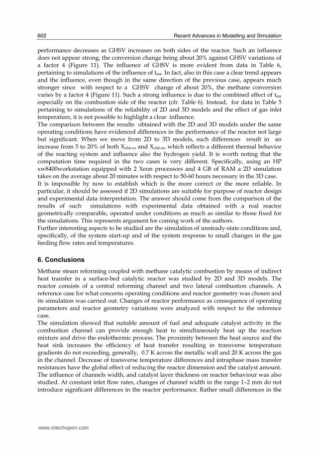
Recent Advances in Modelling and Simulation
602
performance decreases as GHSV increases on both sides of the reactor Such an influence does not appear strong the conversion change being about 20 against GHSV variations of a factor 4 (Figure 11) The influence of GHSV is more evident from data in Table 6 pertaining to simulations of the influence of tmr In fact also in this case a clear trend appears and the influence even though in the same direction of the previous case appears much stronger since with respect to a GHSV change of about 20 the methane conversion varies by a factor 4 (Figure 11) Such a strong influence is due to the combined effect of tmr especially on the combustion side of the reactor (cfr Table 6) Instead for data in Table 5 pertaining to simulations of the reliability of 2D and 3D models and the effect of gas inlet temperature it is not possible to highlight a clear influence The comparison between the results obtained with the 2D and 3D models under the same operating conditions have evidenced differences in the performance of the reactor not large but significant When we move from 2D to 3D models such differences result in an increase from 5 to 20 of both Xch4-co and Xch4-sr which reflects a different thermal behavior of the reacting system and influence also the hydrogen yield It is worth noting that the computation time required in the two cases is very different Specifically using an HP xw8400workstation equipped with 2 Xeon processors and 4 GB of RAM a 2D simulation takes on the average about 20 minutes with respect to 50-60 hours necessary in the 3D case It is impossible by now to establish which is the more correct or the more reliable In particular it should be assessed if 2D simulations are suitable for purpose of reactor design and experimental data interpretation The answer should come from the comparison of the results of such simulations with experimental data obtained with a real reactor geometrically comparable operated under conditions as much as similar to those fixed for the simulations This represents argument for coming work of the authors Further interesting aspects to be studied are the simulation of unsteady-state conditions and specifically of the system start-up and of the system response to small changes in the gas feeding flow rates and temperatures
6 Conclusions
Methane steam reforming coupled with methane catalytic combustion by means of indirect heat transfer in a surface-bed catalytic reactor was studied by 2D and 3D models The reactor consists of a central reforming channel and two lateral combustion channels A reference case for what concerns operating conditions and reactor geometry was chosen and its simulation was carried out Changes of reactor performance as consequence of operating parameters and reactor geometry variations were analyzed with respect to the reference case The simulation showed that suitable amount of fuel and adequate catalyst activity in the combustion channel can provide enough heat to simultaneously heat up the reaction mixture and drive the endothermic process The proximity between the heat source and the heat sink increases the efficiency of heat transfer resulting in transverse temperature gradients do not exceeding generally 07 K across the metallic wall and 20 K across the gas in the channel Decrease of transverse temperature differences and intraphase mass transfer resistances have the global effect of reducing the reactor dimension and the catalyst amount The influence of channels width and catalyst layer thickness on reactor behaviour was also studied At constant inlet flow rates changes of channel width in the range 1ndash2 mm do not introduce significant differences in the reactor performance Rather small differences in the
wwwintechopencom
Modeling of Surface-bed Reactor for Endothermic and Exothermic Reactions Coupling
603
catalyst axial temperature profiles and outlet methane conversions are observed In contrast altering the channel width at constant inlet velocities has strong influence Larger channel width results in lower conversion and smoother axial temperature profiles Intraphase resistances are present even for catalyst thickness of micrometers for both reforming and combustion processes Increasing GHSV that is the inlet flow ratecatalyst volume ratio leads to lower outlet conversions Due to different effect of catalyst layer thickness on reforming and combustion channels there are significant changes in the reactor temperature profile Results indicate that steam reforming of methane in a surface-bed reactor is feasible provided that mass flow rates channels width catalyst loadings and thickness are properly designed
7 Notation
cp specific heat J(mol K) c concentration molm3 Deff effective diffusion coefficient m2s D molecular diffusion coefficient m2s GHSV gas hourly space velocity h-1 k thermal conductivity W(m K) or reaction rate constant Ke equilibrium constant M molecular weight kgmol LEL lower explosivity limit vol
unit vector perpendicular to the flux surface
N molar flux at the boundary mol(m2 s) p partial pressure bar P total pressure bar q thermal flux at the boundary J(m2 s) r reaction rate various dimensions (see eqs 1rsquo 2rsquo and 3rsquo) Rp catalyst pore radius nm STP standard temperature and pressure (298 K and 101 103 Pa) t time s T temperature K ts transverse surface ux Velocity component on the x coordinate
velocity vector
v normal component of velocity at the channel ingress x axial coordinate m X conversion y transverse coordinate m Wc distance between the reactor plates m z vertical coordinate m Greek letters ΔH0r heat of reaction at reference state conditions KJmol c catalyst thickness μm catalyst porosity φ atomic diffusion volume or chemical reaction yield
wwwintechopencom
Recent Advances in Modelling and Simulation
604
θ stoichiometric coefficient ρ density kgm3 τ catalyst tortuosity
Subscripts and superscripts cat catalyst co combustion CH4 methane H2 hydrogen in inlet i chemical species j channel k reaction l phase rm mean residence s metal sheet sr steam reforming 0 channel ingress 1 reforming reaction 2 water gas shift reaction 3 combustion reaction
8 Acknowledgements
The authors gratefully acknowledge the financial support of MIUR under grant PRIN ndeg 2006094333004
9 References
Akers WW amp Camp DP (1955) Kinetics of the methanendashsteam reaction AIChE Journal Vol 1 471ndash475 ISSN0001-1541
Allen DW Gerhard ER amp Likins Jr MR (1975) Kinetics of the MethanendashSteam Reaction Ind Eng Chem Proc Des Dev Vol 14 No 3 256-259 ISSN0196-4305
Aparicio L (1997) Transient Isotopic Studies and Microkinetic Modeling of Methane Reforming over Nickel Catalysts Journal of Catal Vol 165 No 2 262-274 ISSN 0021-9517
Avci AK Trimm DL amp İlsen Oumlnsan Z (2001) Heterogeneous reactor modeling for simulation of catalytic oxidation and steam reforming of methane Chem Eng Sci Vol 56 No 2 641-649 ISSN0009-2509
Bridger GW (1980) The steam reforming of hydrocarbons Catalysis Vol 3 39-69 ISSN0140-0568
Cao C Wang Y amp Rozmiarek RT (2005) Heterogeneous reactor model for steam reforming of methane in a microchannel reactor with microstructured catalysts Catal Today Vol 110 No 1-2 92ndash97 ISSN 0920-5861
Craciun R Shereck B amp Gorte RJ (1998) Kinetic studies of methane steam reforming on ceria-supported Pd Catal Lett Vol 51 No 3ndash4 149-153 ISSN 1011-372x
wwwintechopencom
Modeling of Surface-bed Reactor for Endothermic and Exothermic Reactions Coupling
605
Crowl DA amp Louvar JF (2002) Chemical Process Safety fundamentals with applications 2nd ed Prentice Hall PTR Upper Saddle River NJ USA ISBN 0-13mdash018176-5
De Deken J C Devos E F amp Froment G F (1982) Steam reforming of natural gas Intrinsic kinetics diffusional influences and reactor design ACS Symposium Series 196 181ndash197 ISSN0097-6156
Ehrfeld W amp Hessel V Lowe H (2000) Microreactor Wiley-VCH Verlag GmbH D-69469 ISBN Weinheim Germany
Gosiewski K (2001) Simulations of non-stationary reactors for catalytic conversion of methane to synthesis gas Chem Eng Sci Vol 56 No 4 1501-1510 ISSN
Groppi G Belloli A Tronconi E Forzatti P (1995) A comparison of lumped and distributed models of monolith catalytic combustors Chem Eng Sci Vol 50 No 17 2705ndash2715 ISSN0009-2509
Holladay JD Wang Y amp Jones E (2004) Review of Developments in Portable Hydrogen Production Using Microreactor Technology Chem Rev Vol 104 No 10 4767-4790 ISSN 0009-2665
Hou K amp Hughes R (2001) The kinetics of methane steam reforming over a Ni-Al2O3 catalyst Chem Eng Journal Vol 82 No 1-3 311-328 ISSN 1385-8947
Jamal Y amp Wyszynski M L (1994) On-board generation of hydrogen-rich gaseous fuels a review Int J of Hydrogen Energy Vol 19 No 7 557-572 ISSN 0360-3199
Jensen KF (2001) Microreaction engineering is small better Chem Eng Sci Vol 56 No 2 293-303 ISSN0009-2509
Kolios G Gritsch A Glo1ckler B amp Sorescu G (2004) Novel Reactor Concepts for Thermally Efficient Methane Steam Reforming Modeling and Simulation Ind Eng Chem Res Vol 43 No 16 4796-4808 ISSN0888-5885
Kruger P Blakeley J amp Leaver J (2003) Potential in New Zealand for use of hydrogen as a transportation fuel Int J of Hydrogen Energy Vol 28 No 8 795ndash802 ISSN 0360-3199
Kvamsdal HM Svendsen HF Hertzberg T amp Olsvik O (1999) Dynamic simulation and optimization of a catalytic steam reformer Chem Eng Sci Vol 54 No 13-14 2697-2706 ISSN0009-2509
Lerer M Duic N Alves LM amp Carvalho MG (2006) H2 RES energy planning tool for increasing the penetration of renewable energy sources in island energy supply In New and Renewable Technologies for Sustanaible Development MG Carvalho and NH Afgan (Ed s) 15-30 World Scientific ISBN 10 981-270-505-8 Singapore
Lerou JJ amp Ng KM (1996) Chemical reaction engineering A multiscale approach to a multiobjective task Chem Eng Sci Vol 51 No 10 1595-1614 ISSN0009-2509
Lincoln SF (2006) Challenged Earth ch7 Imperial College Press ISBN 1-86094-526-0 London
Loffler D G Faz C F Sokolovskii V amp Iglesia E (2002) Catalytic separator plate reactor and method of catalytic reforming of fuel to Hydrogen PCT Int Appl WO 0228769 A2
Luna C amp Becerra AM (1997) Kinetics of methane steam reforming on a Ni on alumina-titania catalyst React Kinet Catal Lett Vol 61 No 2 369-374 ISSN 0133-1736
Marschner F Renner HJ amp Boll W (2005) Electronic Encyclopedia Release 2005 7th ed in Ullmannrsquos Encyclopedia of Industrial Chemistry M Bohnet et al (Eds) Vol a12 John Wiley amp Sons ISBN-13 978-3-527-30385-4
wwwintechopencom
Recent Advances in Modelling and Simulation
606
Moore R B amp Raman V (1998) Hydrogen infrastructure for fuel cell transportation Int J of Hydrogen Energy Vol 23 No 7 617-620 ISSN 0360-3199
Perry RH amp Green DW (1999) Perrys Chemical Engineers Handbook (7th Ed) McGraw-Hill ISBN 0-07-049841-5
Robbins F A Zhu H amp Jackson GS (2003) Transient modeling of combined catalytic combustionCH4 steam reformng Catal Today Vol 83 No 1-4 141ndash156 ISSN 0920-5861
Rostrup-Nielsen JR Christiansen LJ amp BakHansen JH (1988) Activity of steam reforming catalysts Role and assessment Appl Catal Vol 43 No 2 287-303 ISSN0166-9834
Rostrup-Nielsen JR (1995) Innovation and the catalytic process industry - the science and challenge Chem Eng Sci Vol 50 No 24 4061-4071 ISSN0009-2509
Rostrup-Nielsen JR Dybkjaer I amp Coulthard GRG (2001) Topical Conf Proc AIChE Spring National Meeting Houston TX April Paper No 1
Rostrup-Nielsen JR (2004) Fuels and Energy for the Future The Role of Catalysis Catal Rev - Science and Engineering Vol 46 No 3ndash4 247-270 ISSN0161-4940
Schubert K Brandner J Fichtner M Linder G Schyhulla U amp Wenka A (2001) Microstructure devices for applications in thermal and chemical process engineering Microscale Thermophys Eng Vol 5 No 1 17-39 ISSN1089-3954
Tronconi E amp Groppi G (2000) A study on the thermal behavior of structured plate-type catalysts with metallic supports for gassolid exothermic reactions Chem Eng Sci Vol 55 Issue 24 December 6021-6036 ISSN0009-2509
Wang Y Johnson BR Cao C Chin Y Rozmiarek RT Gao Y Tonkovich AL (2005) Engineered catalysts for microchannel reactor applications In Microreactor Technology and Process Intensification Y Wang J Holladay (Eds) 65-73 ACS Symposium Series Vol 914 ISBN-13 9780841239234
Xu J amp Froment GF (1989a) Methane steam reforming II Diffusional limitations and reactor simulation AIChE Journal Vol 35 No 1 97-103 ISSN0001-1541
Xu J amp Froment GF (1989b) Methane steam reforming methanation and water-gas shift I Intrinsic kinetics AIChE Journal Vol 35 No 1 88-96 ISSN0001-1541
Zanfir M amp Gavriilidis A (2003) Catalytic Combustion Assisted Methane Steam Reforming Chem Eng Sci Vol 58 No 17 3947ndash 3960 ISSN0009-2509
wwwintechopencom
Modelling and SimulationEdited by Giuseppe Petrone and Giuliano Cammarata
ISBN 978-3-902613-25-7Hard cover 688 pagesPublisher I-Tech Education and PublishingPublished online 01 June 2008Published in print edition June 2008
InTech EuropeUniversity Campus STeP Ri Slavka Krautzeka 83A 51000 Rijeka Croatia Phone +385 (51) 770 447 Fax +385 (51) 686 166wwwintechopencom
InTech ChinaUnit 405 Office Block Hotel Equatorial Shanghai No65 Yan An Road (West) Shanghai 200040 China
Phone +86-21-62489820 Fax +86-21-62489821
This book collects original and innovative research studies concerning modeling and simulation of physicalsystems in a very wide range of applications encompassing micro-electro-mechanical systems measurementinstrumentations catalytic reactors biomechanical applications biological and chemical sensorsmagnetosensitive materials silicon photonic devices electronic devices optical fibers electro-microfluidicsystems composite materials fuel cells indoor air-conditioning systems active magnetic levitation systemsand more Some of the most recent numerical techniques as well as some of the software among the mostaccurate and sophisticated in treating complex systems are applied in order to exhaustively contribute inknowledge advances
How to referenceIn order to correctly reference this scholarly work feel free to copy and paste the following
Salvatore Vaccaro and Paolo Ciambelli (2008) Modeling of Surface-bed Reactor for Endothermic andExothermic Reactions Coupling Modelling and Simulation Giuseppe Petrone and Giuliano Cammarata (Ed)ISBN 978-3-902613-25-7 InTech Available fromhttpwwwintechopencombooksmodelling_and_simulationmodeling_of_surface-bed_reactor_for_endothermic_and_exothermic_reactions_coupling
copy 2008 The Author(s) Licensee IntechOpen This chapter is distributedunder the terms of the Creative Commons Attribution-NonCommercial-ShareAlike-30 License which permits use distribution and reproduction fornon-commercial purposes provided the original is properly cited andderivative works building on this content are distributed under the samelicense
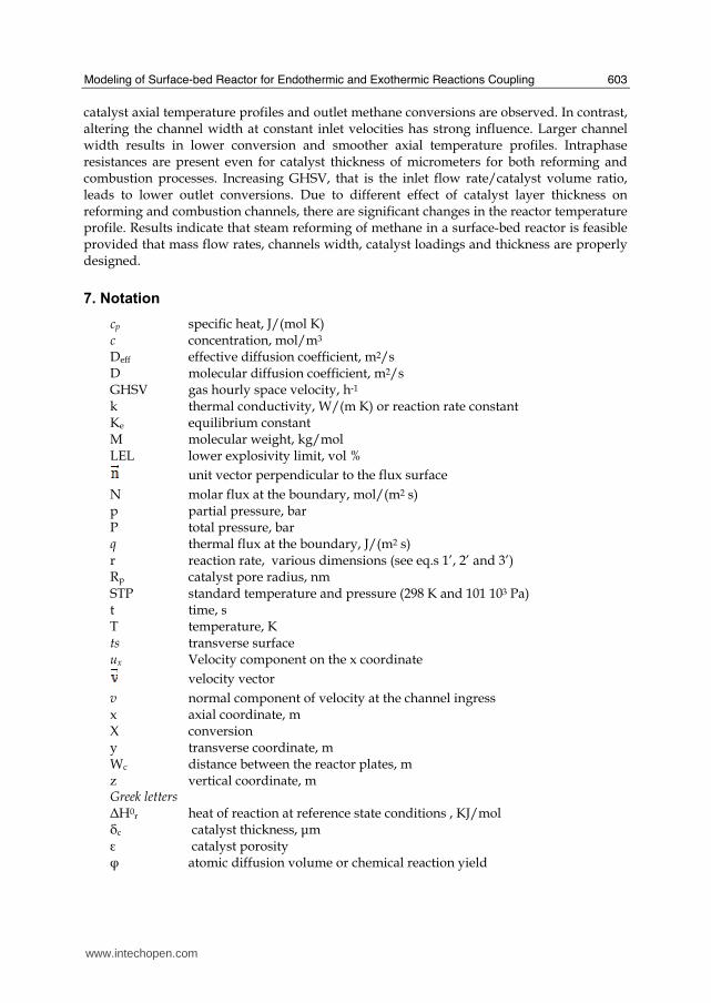
Modeling of Surface-bed Reactor for Endothermic and Exothermic Reactions Coupling
603
catalyst axial temperature profiles and outlet methane conversions are observed In contrast altering the channel width at constant inlet velocities has strong influence Larger channel width results in lower conversion and smoother axial temperature profiles Intraphase resistances are present even for catalyst thickness of micrometers for both reforming and combustion processes Increasing GHSV that is the inlet flow ratecatalyst volume ratio leads to lower outlet conversions Due to different effect of catalyst layer thickness on reforming and combustion channels there are significant changes in the reactor temperature profile Results indicate that steam reforming of methane in a surface-bed reactor is feasible provided that mass flow rates channels width catalyst loadings and thickness are properly designed
7 Notation
cp specific heat J(mol K) c concentration molm3 Deff effective diffusion coefficient m2s D molecular diffusion coefficient m2s GHSV gas hourly space velocity h-1 k thermal conductivity W(m K) or reaction rate constant Ke equilibrium constant M molecular weight kgmol LEL lower explosivity limit vol
unit vector perpendicular to the flux surface
N molar flux at the boundary mol(m2 s) p partial pressure bar P total pressure bar q thermal flux at the boundary J(m2 s) r reaction rate various dimensions (see eqs 1rsquo 2rsquo and 3rsquo) Rp catalyst pore radius nm STP standard temperature and pressure (298 K and 101 103 Pa) t time s T temperature K ts transverse surface ux Velocity component on the x coordinate
velocity vector
v normal component of velocity at the channel ingress x axial coordinate m X conversion y transverse coordinate m Wc distance between the reactor plates m z vertical coordinate m Greek letters ΔH0r heat of reaction at reference state conditions KJmol c catalyst thickness μm catalyst porosity φ atomic diffusion volume or chemical reaction yield
wwwintechopencom
Recent Advances in Modelling and Simulation
604
θ stoichiometric coefficient ρ density kgm3 τ catalyst tortuosity
Subscripts and superscripts cat catalyst co combustion CH4 methane H2 hydrogen in inlet i chemical species j channel k reaction l phase rm mean residence s metal sheet sr steam reforming 0 channel ingress 1 reforming reaction 2 water gas shift reaction 3 combustion reaction
8 Acknowledgements
The authors gratefully acknowledge the financial support of MIUR under grant PRIN ndeg 2006094333004
9 References
Akers WW amp Camp DP (1955) Kinetics of the methanendashsteam reaction AIChE Journal Vol 1 471ndash475 ISSN0001-1541
Allen DW Gerhard ER amp Likins Jr MR (1975) Kinetics of the MethanendashSteam Reaction Ind Eng Chem Proc Des Dev Vol 14 No 3 256-259 ISSN0196-4305
Aparicio L (1997) Transient Isotopic Studies and Microkinetic Modeling of Methane Reforming over Nickel Catalysts Journal of Catal Vol 165 No 2 262-274 ISSN 0021-9517
Avci AK Trimm DL amp İlsen Oumlnsan Z (2001) Heterogeneous reactor modeling for simulation of catalytic oxidation and steam reforming of methane Chem Eng Sci Vol 56 No 2 641-649 ISSN0009-2509
Bridger GW (1980) The steam reforming of hydrocarbons Catalysis Vol 3 39-69 ISSN0140-0568
Cao C Wang Y amp Rozmiarek RT (2005) Heterogeneous reactor model for steam reforming of methane in a microchannel reactor with microstructured catalysts Catal Today Vol 110 No 1-2 92ndash97 ISSN 0920-5861
Craciun R Shereck B amp Gorte RJ (1998) Kinetic studies of methane steam reforming on ceria-supported Pd Catal Lett Vol 51 No 3ndash4 149-153 ISSN 1011-372x
wwwintechopencom
Modeling of Surface-bed Reactor for Endothermic and Exothermic Reactions Coupling
605
Crowl DA amp Louvar JF (2002) Chemical Process Safety fundamentals with applications 2nd ed Prentice Hall PTR Upper Saddle River NJ USA ISBN 0-13mdash018176-5
De Deken J C Devos E F amp Froment G F (1982) Steam reforming of natural gas Intrinsic kinetics diffusional influences and reactor design ACS Symposium Series 196 181ndash197 ISSN0097-6156
Ehrfeld W amp Hessel V Lowe H (2000) Microreactor Wiley-VCH Verlag GmbH D-69469 ISBN Weinheim Germany
Gosiewski K (2001) Simulations of non-stationary reactors for catalytic conversion of methane to synthesis gas Chem Eng Sci Vol 56 No 4 1501-1510 ISSN
Groppi G Belloli A Tronconi E Forzatti P (1995) A comparison of lumped and distributed models of monolith catalytic combustors Chem Eng Sci Vol 50 No 17 2705ndash2715 ISSN0009-2509
Holladay JD Wang Y amp Jones E (2004) Review of Developments in Portable Hydrogen Production Using Microreactor Technology Chem Rev Vol 104 No 10 4767-4790 ISSN 0009-2665
Hou K amp Hughes R (2001) The kinetics of methane steam reforming over a Ni-Al2O3 catalyst Chem Eng Journal Vol 82 No 1-3 311-328 ISSN 1385-8947
Jamal Y amp Wyszynski M L (1994) On-board generation of hydrogen-rich gaseous fuels a review Int J of Hydrogen Energy Vol 19 No 7 557-572 ISSN 0360-3199
Jensen KF (2001) Microreaction engineering is small better Chem Eng Sci Vol 56 No 2 293-303 ISSN0009-2509
Kolios G Gritsch A Glo1ckler B amp Sorescu G (2004) Novel Reactor Concepts for Thermally Efficient Methane Steam Reforming Modeling and Simulation Ind Eng Chem Res Vol 43 No 16 4796-4808 ISSN0888-5885
Kruger P Blakeley J amp Leaver J (2003) Potential in New Zealand for use of hydrogen as a transportation fuel Int J of Hydrogen Energy Vol 28 No 8 795ndash802 ISSN 0360-3199
Kvamsdal HM Svendsen HF Hertzberg T amp Olsvik O (1999) Dynamic simulation and optimization of a catalytic steam reformer Chem Eng Sci Vol 54 No 13-14 2697-2706 ISSN0009-2509
Lerer M Duic N Alves LM amp Carvalho MG (2006) H2 RES energy planning tool for increasing the penetration of renewable energy sources in island energy supply In New and Renewable Technologies for Sustanaible Development MG Carvalho and NH Afgan (Ed s) 15-30 World Scientific ISBN 10 981-270-505-8 Singapore
Lerou JJ amp Ng KM (1996) Chemical reaction engineering A multiscale approach to a multiobjective task Chem Eng Sci Vol 51 No 10 1595-1614 ISSN0009-2509
Lincoln SF (2006) Challenged Earth ch7 Imperial College Press ISBN 1-86094-526-0 London
Loffler D G Faz C F Sokolovskii V amp Iglesia E (2002) Catalytic separator plate reactor and method of catalytic reforming of fuel to Hydrogen PCT Int Appl WO 0228769 A2
Luna C amp Becerra AM (1997) Kinetics of methane steam reforming on a Ni on alumina-titania catalyst React Kinet Catal Lett Vol 61 No 2 369-374 ISSN 0133-1736
Marschner F Renner HJ amp Boll W (2005) Electronic Encyclopedia Release 2005 7th ed in Ullmannrsquos Encyclopedia of Industrial Chemistry M Bohnet et al (Eds) Vol a12 John Wiley amp Sons ISBN-13 978-3-527-30385-4
wwwintechopencom
Recent Advances in Modelling and Simulation
606
Moore R B amp Raman V (1998) Hydrogen infrastructure for fuel cell transportation Int J of Hydrogen Energy Vol 23 No 7 617-620 ISSN 0360-3199
Perry RH amp Green DW (1999) Perrys Chemical Engineers Handbook (7th Ed) McGraw-Hill ISBN 0-07-049841-5
Robbins F A Zhu H amp Jackson GS (2003) Transient modeling of combined catalytic combustionCH4 steam reformng Catal Today Vol 83 No 1-4 141ndash156 ISSN 0920-5861
Rostrup-Nielsen JR Christiansen LJ amp BakHansen JH (1988) Activity of steam reforming catalysts Role and assessment Appl Catal Vol 43 No 2 287-303 ISSN0166-9834
Rostrup-Nielsen JR (1995) Innovation and the catalytic process industry - the science and challenge Chem Eng Sci Vol 50 No 24 4061-4071 ISSN0009-2509
Rostrup-Nielsen JR Dybkjaer I amp Coulthard GRG (2001) Topical Conf Proc AIChE Spring National Meeting Houston TX April Paper No 1
Rostrup-Nielsen JR (2004) Fuels and Energy for the Future The Role of Catalysis Catal Rev - Science and Engineering Vol 46 No 3ndash4 247-270 ISSN0161-4940
Schubert K Brandner J Fichtner M Linder G Schyhulla U amp Wenka A (2001) Microstructure devices for applications in thermal and chemical process engineering Microscale Thermophys Eng Vol 5 No 1 17-39 ISSN1089-3954
Tronconi E amp Groppi G (2000) A study on the thermal behavior of structured plate-type catalysts with metallic supports for gassolid exothermic reactions Chem Eng Sci Vol 55 Issue 24 December 6021-6036 ISSN0009-2509
Wang Y Johnson BR Cao C Chin Y Rozmiarek RT Gao Y Tonkovich AL (2005) Engineered catalysts for microchannel reactor applications In Microreactor Technology and Process Intensification Y Wang J Holladay (Eds) 65-73 ACS Symposium Series Vol 914 ISBN-13 9780841239234
Xu J amp Froment GF (1989a) Methane steam reforming II Diffusional limitations and reactor simulation AIChE Journal Vol 35 No 1 97-103 ISSN0001-1541
Xu J amp Froment GF (1989b) Methane steam reforming methanation and water-gas shift I Intrinsic kinetics AIChE Journal Vol 35 No 1 88-96 ISSN0001-1541
Zanfir M amp Gavriilidis A (2003) Catalytic Combustion Assisted Methane Steam Reforming Chem Eng Sci Vol 58 No 17 3947ndash 3960 ISSN0009-2509
wwwintechopencom
Modelling and SimulationEdited by Giuseppe Petrone and Giuliano Cammarata
ISBN 978-3-902613-25-7Hard cover 688 pagesPublisher I-Tech Education and PublishingPublished online 01 June 2008Published in print edition June 2008
InTech EuropeUniversity Campus STeP Ri Slavka Krautzeka 83A 51000 Rijeka Croatia Phone +385 (51) 770 447 Fax +385 (51) 686 166wwwintechopencom
InTech ChinaUnit 405 Office Block Hotel Equatorial Shanghai No65 Yan An Road (West) Shanghai 200040 China
Phone +86-21-62489820 Fax +86-21-62489821
This book collects original and innovative research studies concerning modeling and simulation of physicalsystems in a very wide range of applications encompassing micro-electro-mechanical systems measurementinstrumentations catalytic reactors biomechanical applications biological and chemical sensorsmagnetosensitive materials silicon photonic devices electronic devices optical fibers electro-microfluidicsystems composite materials fuel cells indoor air-conditioning systems active magnetic levitation systemsand more Some of the most recent numerical techniques as well as some of the software among the mostaccurate and sophisticated in treating complex systems are applied in order to exhaustively contribute inknowledge advances
How to referenceIn order to correctly reference this scholarly work feel free to copy and paste the following
Salvatore Vaccaro and Paolo Ciambelli (2008) Modeling of Surface-bed Reactor for Endothermic andExothermic Reactions Coupling Modelling and Simulation Giuseppe Petrone and Giuliano Cammarata (Ed)ISBN 978-3-902613-25-7 InTech Available fromhttpwwwintechopencombooksmodelling_and_simulationmodeling_of_surface-bed_reactor_for_endothermic_and_exothermic_reactions_coupling
copy 2008 The Author(s) Licensee IntechOpen This chapter is distributedunder the terms of the Creative Commons Attribution-NonCommercial-ShareAlike-30 License which permits use distribution and reproduction fornon-commercial purposes provided the original is properly cited andderivative works building on this content are distributed under the samelicense
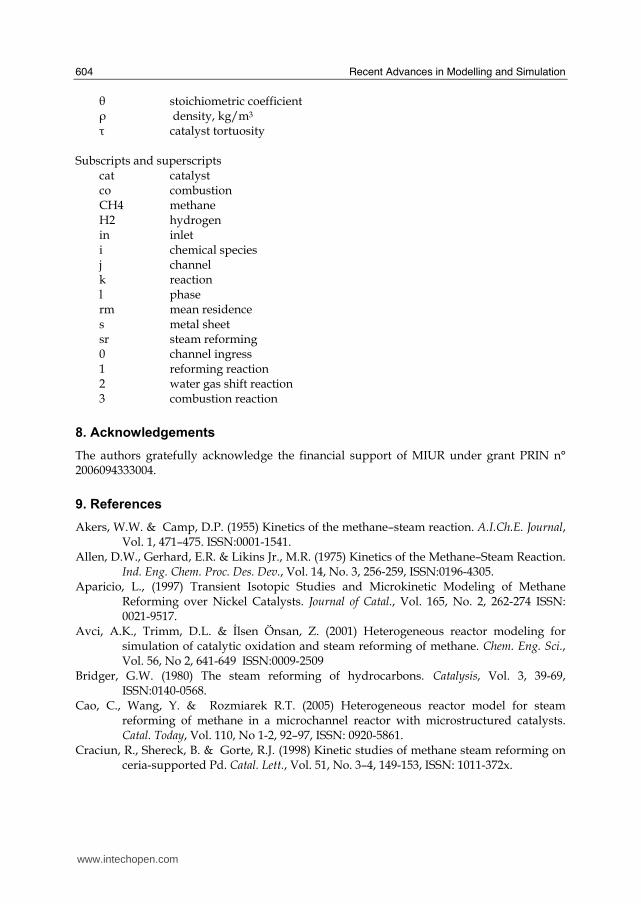
Recent Advances in Modelling and Simulation
604
θ stoichiometric coefficient ρ density kgm3 τ catalyst tortuosity
Subscripts and superscripts cat catalyst co combustion CH4 methane H2 hydrogen in inlet i chemical species j channel k reaction l phase rm mean residence s metal sheet sr steam reforming 0 channel ingress 1 reforming reaction 2 water gas shift reaction 3 combustion reaction
8 Acknowledgements
The authors gratefully acknowledge the financial support of MIUR under grant PRIN ndeg 2006094333004
9 References
Akers WW amp Camp DP (1955) Kinetics of the methanendashsteam reaction AIChE Journal Vol 1 471ndash475 ISSN0001-1541
Allen DW Gerhard ER amp Likins Jr MR (1975) Kinetics of the MethanendashSteam Reaction Ind Eng Chem Proc Des Dev Vol 14 No 3 256-259 ISSN0196-4305
Aparicio L (1997) Transient Isotopic Studies and Microkinetic Modeling of Methane Reforming over Nickel Catalysts Journal of Catal Vol 165 No 2 262-274 ISSN 0021-9517
Avci AK Trimm DL amp İlsen Oumlnsan Z (2001) Heterogeneous reactor modeling for simulation of catalytic oxidation and steam reforming of methane Chem Eng Sci Vol 56 No 2 641-649 ISSN0009-2509
Bridger GW (1980) The steam reforming of hydrocarbons Catalysis Vol 3 39-69 ISSN0140-0568
Cao C Wang Y amp Rozmiarek RT (2005) Heterogeneous reactor model for steam reforming of methane in a microchannel reactor with microstructured catalysts Catal Today Vol 110 No 1-2 92ndash97 ISSN 0920-5861
Craciun R Shereck B amp Gorte RJ (1998) Kinetic studies of methane steam reforming on ceria-supported Pd Catal Lett Vol 51 No 3ndash4 149-153 ISSN 1011-372x
wwwintechopencom
Modeling of Surface-bed Reactor for Endothermic and Exothermic Reactions Coupling
605
Crowl DA amp Louvar JF (2002) Chemical Process Safety fundamentals with applications 2nd ed Prentice Hall PTR Upper Saddle River NJ USA ISBN 0-13mdash018176-5
De Deken J C Devos E F amp Froment G F (1982) Steam reforming of natural gas Intrinsic kinetics diffusional influences and reactor design ACS Symposium Series 196 181ndash197 ISSN0097-6156
Ehrfeld W amp Hessel V Lowe H (2000) Microreactor Wiley-VCH Verlag GmbH D-69469 ISBN Weinheim Germany
Gosiewski K (2001) Simulations of non-stationary reactors for catalytic conversion of methane to synthesis gas Chem Eng Sci Vol 56 No 4 1501-1510 ISSN
Groppi G Belloli A Tronconi E Forzatti P (1995) A comparison of lumped and distributed models of monolith catalytic combustors Chem Eng Sci Vol 50 No 17 2705ndash2715 ISSN0009-2509
Holladay JD Wang Y amp Jones E (2004) Review of Developments in Portable Hydrogen Production Using Microreactor Technology Chem Rev Vol 104 No 10 4767-4790 ISSN 0009-2665
Hou K amp Hughes R (2001) The kinetics of methane steam reforming over a Ni-Al2O3 catalyst Chem Eng Journal Vol 82 No 1-3 311-328 ISSN 1385-8947
Jamal Y amp Wyszynski M L (1994) On-board generation of hydrogen-rich gaseous fuels a review Int J of Hydrogen Energy Vol 19 No 7 557-572 ISSN 0360-3199
Jensen KF (2001) Microreaction engineering is small better Chem Eng Sci Vol 56 No 2 293-303 ISSN0009-2509
Kolios G Gritsch A Glo1ckler B amp Sorescu G (2004) Novel Reactor Concepts for Thermally Efficient Methane Steam Reforming Modeling and Simulation Ind Eng Chem Res Vol 43 No 16 4796-4808 ISSN0888-5885
Kruger P Blakeley J amp Leaver J (2003) Potential in New Zealand for use of hydrogen as a transportation fuel Int J of Hydrogen Energy Vol 28 No 8 795ndash802 ISSN 0360-3199
Kvamsdal HM Svendsen HF Hertzberg T amp Olsvik O (1999) Dynamic simulation and optimization of a catalytic steam reformer Chem Eng Sci Vol 54 No 13-14 2697-2706 ISSN0009-2509
Lerer M Duic N Alves LM amp Carvalho MG (2006) H2 RES energy planning tool for increasing the penetration of renewable energy sources in island energy supply In New and Renewable Technologies for Sustanaible Development MG Carvalho and NH Afgan (Ed s) 15-30 World Scientific ISBN 10 981-270-505-8 Singapore
Lerou JJ amp Ng KM (1996) Chemical reaction engineering A multiscale approach to a multiobjective task Chem Eng Sci Vol 51 No 10 1595-1614 ISSN0009-2509
Lincoln SF (2006) Challenged Earth ch7 Imperial College Press ISBN 1-86094-526-0 London
Loffler D G Faz C F Sokolovskii V amp Iglesia E (2002) Catalytic separator plate reactor and method of catalytic reforming of fuel to Hydrogen PCT Int Appl WO 0228769 A2
Luna C amp Becerra AM (1997) Kinetics of methane steam reforming on a Ni on alumina-titania catalyst React Kinet Catal Lett Vol 61 No 2 369-374 ISSN 0133-1736
Marschner F Renner HJ amp Boll W (2005) Electronic Encyclopedia Release 2005 7th ed in Ullmannrsquos Encyclopedia of Industrial Chemistry M Bohnet et al (Eds) Vol a12 John Wiley amp Sons ISBN-13 978-3-527-30385-4
wwwintechopencom
Recent Advances in Modelling and Simulation
606
Moore R B amp Raman V (1998) Hydrogen infrastructure for fuel cell transportation Int J of Hydrogen Energy Vol 23 No 7 617-620 ISSN 0360-3199
Perry RH amp Green DW (1999) Perrys Chemical Engineers Handbook (7th Ed) McGraw-Hill ISBN 0-07-049841-5
Robbins F A Zhu H amp Jackson GS (2003) Transient modeling of combined catalytic combustionCH4 steam reformng Catal Today Vol 83 No 1-4 141ndash156 ISSN 0920-5861
Rostrup-Nielsen JR Christiansen LJ amp BakHansen JH (1988) Activity of steam reforming catalysts Role and assessment Appl Catal Vol 43 No 2 287-303 ISSN0166-9834
Rostrup-Nielsen JR (1995) Innovation and the catalytic process industry - the science and challenge Chem Eng Sci Vol 50 No 24 4061-4071 ISSN0009-2509
Rostrup-Nielsen JR Dybkjaer I amp Coulthard GRG (2001) Topical Conf Proc AIChE Spring National Meeting Houston TX April Paper No 1
Rostrup-Nielsen JR (2004) Fuels and Energy for the Future The Role of Catalysis Catal Rev - Science and Engineering Vol 46 No 3ndash4 247-270 ISSN0161-4940
Schubert K Brandner J Fichtner M Linder G Schyhulla U amp Wenka A (2001) Microstructure devices for applications in thermal and chemical process engineering Microscale Thermophys Eng Vol 5 No 1 17-39 ISSN1089-3954
Tronconi E amp Groppi G (2000) A study on the thermal behavior of structured plate-type catalysts with metallic supports for gassolid exothermic reactions Chem Eng Sci Vol 55 Issue 24 December 6021-6036 ISSN0009-2509
Wang Y Johnson BR Cao C Chin Y Rozmiarek RT Gao Y Tonkovich AL (2005) Engineered catalysts for microchannel reactor applications In Microreactor Technology and Process Intensification Y Wang J Holladay (Eds) 65-73 ACS Symposium Series Vol 914 ISBN-13 9780841239234
Xu J amp Froment GF (1989a) Methane steam reforming II Diffusional limitations and reactor simulation AIChE Journal Vol 35 No 1 97-103 ISSN0001-1541
Xu J amp Froment GF (1989b) Methane steam reforming methanation and water-gas shift I Intrinsic kinetics AIChE Journal Vol 35 No 1 88-96 ISSN0001-1541
Zanfir M amp Gavriilidis A (2003) Catalytic Combustion Assisted Methane Steam Reforming Chem Eng Sci Vol 58 No 17 3947ndash 3960 ISSN0009-2509
wwwintechopencom
Modelling and SimulationEdited by Giuseppe Petrone and Giuliano Cammarata
ISBN 978-3-902613-25-7Hard cover 688 pagesPublisher I-Tech Education and PublishingPublished online 01 June 2008Published in print edition June 2008
InTech EuropeUniversity Campus STeP Ri Slavka Krautzeka 83A 51000 Rijeka Croatia Phone +385 (51) 770 447 Fax +385 (51) 686 166wwwintechopencom
InTech ChinaUnit 405 Office Block Hotel Equatorial Shanghai No65 Yan An Road (West) Shanghai 200040 China
Phone +86-21-62489820 Fax +86-21-62489821
This book collects original and innovative research studies concerning modeling and simulation of physicalsystems in a very wide range of applications encompassing micro-electro-mechanical systems measurementinstrumentations catalytic reactors biomechanical applications biological and chemical sensorsmagnetosensitive materials silicon photonic devices electronic devices optical fibers electro-microfluidicsystems composite materials fuel cells indoor air-conditioning systems active magnetic levitation systemsand more Some of the most recent numerical techniques as well as some of the software among the mostaccurate and sophisticated in treating complex systems are applied in order to exhaustively contribute inknowledge advances
How to referenceIn order to correctly reference this scholarly work feel free to copy and paste the following
Salvatore Vaccaro and Paolo Ciambelli (2008) Modeling of Surface-bed Reactor for Endothermic andExothermic Reactions Coupling Modelling and Simulation Giuseppe Petrone and Giuliano Cammarata (Ed)ISBN 978-3-902613-25-7 InTech Available fromhttpwwwintechopencombooksmodelling_and_simulationmodeling_of_surface-bed_reactor_for_endothermic_and_exothermic_reactions_coupling
copy 2008 The Author(s) Licensee IntechOpen This chapter is distributedunder the terms of the Creative Commons Attribution-NonCommercial-ShareAlike-30 License which permits use distribution and reproduction fornon-commercial purposes provided the original is properly cited andderivative works building on this content are distributed under the samelicense

copy 2008 The Author(s) Licensee IntechOpen This chapter is distributedunder the terms of the Creative Commons Attribution-NonCommercial-ShareAlike-30 License which permits use distribution and reproduction fornon-commercial purposes provided the original is properly cited andderivative works building on this content are distributed under the samelicense