Embed Size (px)
Citation preview

23rd
International Conference
ENGINEERING MECHANICS 2017
Svratka, Czech Republic, 15 – 18 May 2017
MODELING OF PRESTRESSED BOLT CONNECTION IN LS-DYNA
CRASH TEST ANALYSIS OF ROAD INFRACTRUCTURE
M. Stopel*, A. Cichański
**, D. Skibicki
***
Abstract: Bolted connections are the most frequently used type of separable connections in the construction
of machines and devices. In this study possibilities of modelling of this type of connections in the LS-Dyna
environment with reference to designing a supporting construction of road infrastructure have been
presented. Modelling a safety connector with the use of BEAM elements brings satisfactory results mainly
when object of interest is a whole structure not a bolt only. In the case when mainly mechanisms of damage
of a bolted connection are analysed it is justifiable to model a safety connector with the use of SOLID
elements.
Keywords: LS-Dyna, Road infrastructure, Bolt connection, Preload.
1. Introduction
With reference to a new safety standard PN-EN 12767 newly designed structures located in the road
verge must meet the passive safety requirements. In the supporting construction of road infrastructure,
proposed by the authors (Cichański, 2015), a safety connector has been used, which is subject to damage
as a result of a crash of a moving vehicle into the construction. The main element determining the
effectiveness of a safety connector is a bolted connection. However, it should also transfer loads resulting
from the conditions of exploitation. Because of this it is very important to precisely specify, during a
construction process, geometric and material properties of a connection, which would have an impact on
the operation of a safety connector. Analytical calculations often occur to be insufficient. In such cases
numerical simulations are successfully applied based on the finite element method. Then there is a series
of issues to be solved and one of the basic ones is a manner of modelling a connection (Hadjioannou,
2016).
In the study the issue of modelling pre-load in safety connectors has been raised. Selected methods of
modelling have been discussed. For consideration issue presented in the work the subarea of the road
mast was chosen. Numerical analyses for a chosen subarea of a road infrastructure mast have been
conducted. As a results of analysis normal and shear forces appearing in a bolt connector and reduced
stresses were presented.
2. Object and conditions of tests
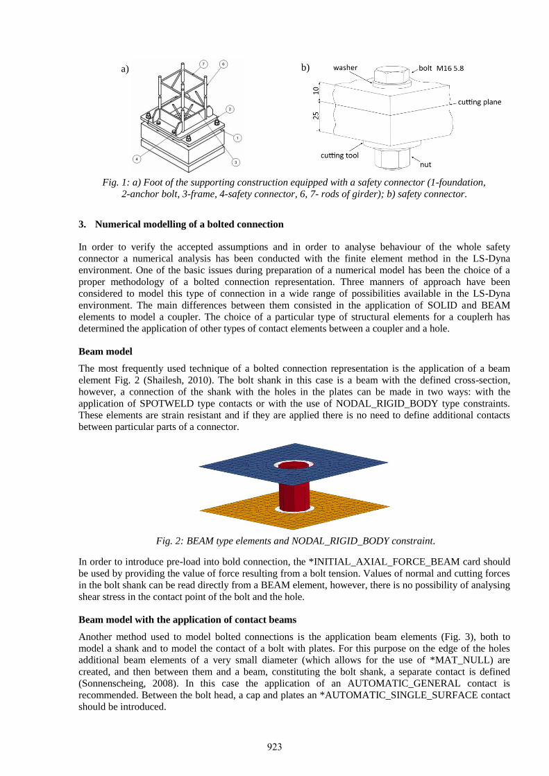
The foot of the mast being analysed has been presented in Fig. 1a. From the presented structure a subarea
has been cut out, which is, namely, a safety connector being designed. It has been subject to further
analysis in this study Fig. 1b. The lower plate of the thickness of 25 mm has been fixed by taking away
degrees of freedom in all the directions. Constant translation has been applied to the bottom plate of the
thickness of 10mm. Two analyses have been made. One with the pre-load of the 100 MPa introduced to
the bolt shank and the other without pre-load.
* Ing. Michał Stopel.: University of Science and Technology, Mechanical Engineering Faculty, Kaliskiego 7; 85-796,
Bydgoszcz; PL, [email protected] ** Ing. Artur Cichański, PhD.: University of Science and Technology, Mechanical Engineering Faculty, Kaliskiego 7; 85-796,
Bydgoszcz; PL, [email protected] *** Prof. Dariusz Skibicki.: University of Science and Technology, Mechanical Engineering Faculty, Kaliskiego 7; 85-796,
Bydgoszcz; PL, [email protected]
922
3
a)
b)
Fig. 1: a) Foot of the supporting construction equipped with a safety connector (1-foundation,
2-anchor bolt, 3-frame, 4-safety connector, 6, 7- rods of girder); b) safety connector.
3. Numerical modelling of a bolted connection
In order to verify the accepted assumptions and in order to analyse behaviour of the whole safety
connector a numerical analysis has been conducted with the finite element method in the LS-Dyna
environment. One of the basic issues during preparation of a numerical model has been the choice of a
proper methodology of a bolted connection representation. Three manners of approach have been
considered to model this type of connection in a wide range of possibilities available in the LS-Dyna
environment. The main differences between them consisted in the application of SOLID and BEAM
elements to model a coupler. The choice of a particular type of structural elements for a couplerh has
determined the application of other types of contact elements between a coupler and a hole.
Beam model
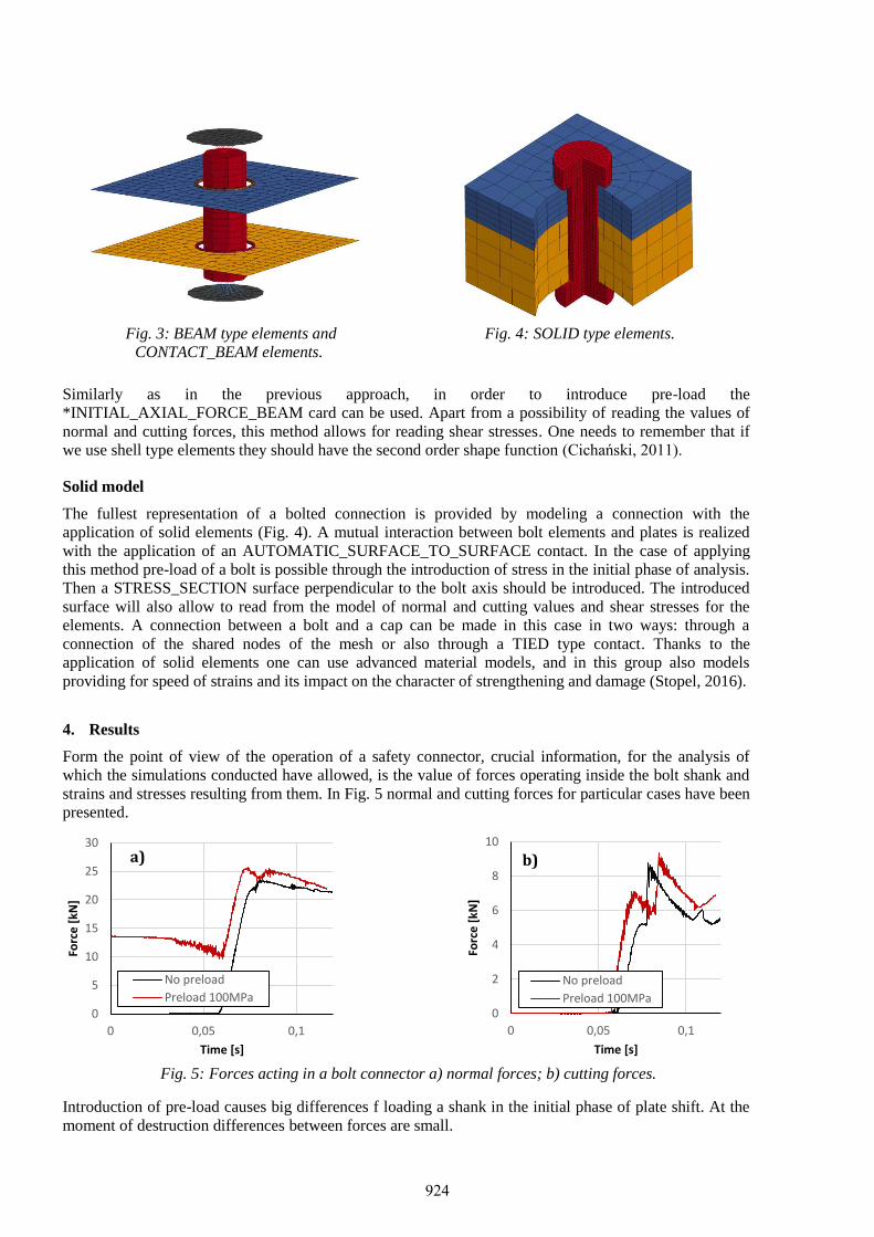
The most frequently used technique of a bolted connection representation is the application of a beam
element Fig. 2 (Shailesh, 2010). The bolt shank in this case is a beam with the defined cross-section,
however, a connection of the shank with the holes in the plates can be made in two ways: with the
application of SPOTWELD type contacts or with the use of NODAL_RIGID_BODY type constraints.
These elements are strain resistant and if they are applied there is no need to define additional contacts
between particular parts of a connector.
Fig. 2: BEAM type elements and NODAL_RIGID_BODY constraint.
In order to introduce pre-load into bold connection, the *INITIAL_AXIAL_FORCE_BEAM card should
be used by providing the value of force resulting from a bolt tension. Values of normal and cutting forces
in the bolt shank can be read directly from a BEAM element, however, there is no possibility of analysing
shear stress in the contact point of the bolt and the hole.
Beam model with the application of contact beams
Another method used to model bolted connections is the application beam elements (Fig. 3), both to
model a shank and to model the contact of a bolt with plates. For this purpose on the edge of the holes
additional beam elements of a very small diameter (which allows for the use of *MAT_NULL) are
created, and then between them and a beam, constituting the bolt shank, a separate contact is defined
(Sonnenscheing, 2008). In this case the application of an AUTOMATIC_GENERAL contact is
recommended. Between the bolt head, a cap and plates an *AUTOMATIC_SINGLE_SURFACE contact
should be introduced.
923
4
Fig. 3: BEAM type elements and
CONTACT_BEAM elements.
Fig. 4: SOLID type elements.
Similarly as in the previous approach, in order to introduce pre-load the
*INITIAL_AXIAL_FORCE_BEAM card can be used. Apart from a possibility of reading the values of
normal and cutting forces, this method allows for reading shear stresses. One needs to remember that if
we use shell type elements they should have the second order shape function (Cichański, 2011).
Solid model
The fullest representation of a bolted connection is provided by modeling a connection with the
application of solid elements (Fig. 4). A mutual interaction between bolt elements and plates is realized
with the application of an AUTOMATIC_SURFACE_TO_SURFACE contact. In the case of applying
this method pre-load of a bolt is possible through the introduction of stress in the initial phase of analysis.
Then a STRESS_SECTION surface perpendicular to the bolt axis should be introduced. The introduced
surface will also allow to read from the model of normal and cutting values and shear stresses for the
elements. A connection between a bolt and a cap can be made in this case in two ways: through a
connection of the shared nodes of the mesh or also through a TIED type contact. Thanks to the
application of solid elements one can use advanced material models, and in this group also models
providing for speed of strains and its impact on the character of strengthening and damage (Stopel, 2016).
4. Results
Form the point of view of the operation of a safety connector, crucial information, for the analysis of
which the simulations conducted have allowed, is the value of forces operating inside the bolt shank and
strains and stresses resulting from them. In Fig. 5 normal and cutting forces for particular cases have been
presented.
Fig. 5: Forces acting in a bolt connector a) normal forces; b) cutting forces.
Introduction of pre-load causes big differences f loading a shank in the initial phase of plate shift. At the
moment of destruction differences between forces are small.
0
5
10
15
20
25
30
0 0,05 0,1
Forc
e [
kN]
Time [s]
a)
No preload
Preload 100MPa0
2
4
6
8
10
0 0,05 0,1
Forc
e [
kN]
Time [s]
b)
No preload
Preload 100MPa
924
5
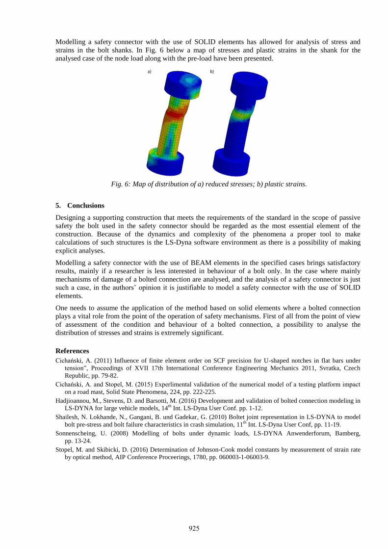
Modelling a safety connector with the use of SOLID elements has allowed for analysis of stress and
strains in the bolt shanks. In Fig. 6 below a map of stresses and plastic strains in the shank for the
analysed case of the node load along with the pre-load have been presented.
Fig. 6: Map of distribution of a) reduced stresses; b) plastic strains.
5. Conclusions
Designing a supporting construction that meets the requirements of the standard in the scope of passive
safety the bolt used in the safety connector should be regarded as the most essential element of the
construction. Because of the dynamics and complexity of the phenomena a proper tool to make
calculations of such structures is the LS-Dyna software environment as there is a possibility of making
explicit analyses.
Modelling a safety connector with the use of BEAM elements in the specified cases brings satisfactory
results, mainly if a researcher is less interested in behaviour of a bolt only. In the case where mainly
mechanisms of damage of a bolted connection are analysed, and the analysis of a safety connector is just
such a case, in the authors’ opinion it is justifiable to model a safety connector with the use of SOLID
elements.
One needs to assume the application of the method based on solid elements where a bolted connection
plays a vital role from the point of the operation of safety mechanisms. First of all from the point of view
of assessment of the condition and behaviour of a bolted connection, a possibility to analyse the
distribution of stresses and strains is extremely significant.
References
Cichański, A. (2011) Influence of finite element order on SCF precision for U-shaped notches in flat bars under
tension”, Proceedings of XVII 17th International Conference Engineering Mechanics 2011, Svratka, Czech
Republic, pp. 79-82.
Cichański, A. and Stopel, M. (2015) Experlimental validation of the numerical model of a testing platform impact
on a road mast, Solid State Phenomena, 224, pp. 222-225.
Hadjioannou, M., Stevens, D. and Barsotti, M. (2016) Development and validation of bolted connection modeling in
LS-DYNA for large vehicle models, 14th
Int. LS-Dyna User Conf. pp. 1-12.
Shailesh, N. Lokhande, N., Gangani, B. und Gadekar, G. (2010) Boltet joint representation in LS-DYNA to model
bolt pre-stress and bolt failure characteristics in crash simulation, 11th
Int. LS-Dyna User Conf, pp. 11-19.
Sonnenscheing, U. (2008) Modelling of bolts under dynamic loads, LS-DYNA Anwenderforum, Bamberg,
pp. 13-24.
Stopel, M. and Skibicki, D. (2016) Determination of Johnson-Cook model constants by measurement of strain rate
by optical method, AIP Conference Proceerings, 1780, pp. 060003-1-06003-9.
925