Embed Size (px)
Citation preview
8
Modeling of Macrostructure Formation during the Solidification by using
Frontal Cellular Automata
Dmytro S. Svyetlichnyy AGH University of Science and Technology
Poland
1. Introduction
Prediction of the microstructure and properties is one of the most important problems in materials science. There are different methods that are used for modeling of the microstructure evolution, among them are the front tracking method (Thompson et al., 1987; Frost et al., 1988), the phase-field models (Fan & Chen, 1997), the cellular automata (CA) models (Davies, 1997), vertex models (Weygand at al., 2001), Monte Carlo Potts models (Holm at al., 2001) and the finite element method (FEM) based models (Bernacki at al. 2007). Application of CA models, for simulation of the different phenomena in materials, has increased significantly in the resent years. CA approach is used for modeling of solidification (Rappaz & Gandin, 1993; Raabe, 2004), dynamic and static recrystallization (Kumar et al., 1998; Hurley & Humphreys, 2003; Qian & Guo, 2004), phase transformation (Das et al., 2002), grain refinement (Svyetlichnyy et al., 2008), micro-shear band and shear band propagation. The main asset of CA based methods is their ability for a close correlation between the microstructure and the mechanical properties during both micro- and meso-scale simulation. The joint methods based on CA and FEM improve accuracy of the coupled phenomena simulation during the forming processes. CA based models have been developed and are being used mostly as two-dimensional (2D) versions. However, three-dimensional (3D) models have been published as well. The 2D CA models are simpler and faster. They also include less elements and connections. They are based on less complicated algorithms. They are also simpler for design, implementation and more useful for visualization. However, there are some problems which have been solved in the 2D CA, but are still unsolved in 3D CA. Microstructure evolution is in general the three-dimensional problem and the results obtained by 2D CA cannot always be directly transferred to a real 3D process. However, the 3D models require significantly more memory and time for the calculation. This is because they have more cells and each cell has more neighbors. The memory and also the processing time problems can be potentially solved by parallelization using several processors or computers working in the network. Another approach that has been applied recently, along with the parallelization, is based on development of different algorithms capable of using appropriate properties of the special CA types. One of these algorithms, known as the frontal CA (FCA) and developed for simulation of the microstructure evolution, is described by Svyetlichnyy (2010).
www.intechopen.com
Cellular Automata - Innovative Modelling for Science and Engineering
180
The objective of the paper is development of a model and tools for modeling the macroscopic structure formation during the solidification in continuous casting line, based on technique of cellular automata, which can cooperate with finite element model. The model is described in the paper, as well as some examples of simulation of the macrostructure formation during the continuous casting simulation using the developed model are presented.
2. Frontal cellular automata
The first CA model was developed as the 2D version. The simulation using this model can be carried out with good resolution on the relatively big space, for example 1000x1000 cells. However, the real microstructure evolution is mainly the 3D process. Hence, appropriate CA should be applied for the modeling. At this point, “the curse of dimensionality” is reached also known as the Hughes effect, when both the number of the cells and the calculation time arise enormously (Svyetlichnyy, 2010). The more cells are used, the shorter is the step of calculation. Thus, the calculation time for the 3D space can be evaluated as the fourth power of the number of cells on a side. As a result, the first trial of the classical CA application in 3D space could be the last one because of its impracticality. The 2D calculation lasts for several minutes, while the same calculation in 3D space lasts for several days. Let’s consider a process of the grain growth. There are three areas that can be picked out in each process variant. In the first area, there are no changes of the initial state. The changes are completed in the second one. In the third area, the cells change their state. These areas are unlabeled and can be used in the calculations. The first and also the second area have to be excluded from the calculation in the current step because no change is expected. The main idea of the FCA is that the only thin cell layer located near the front of the changes, i.e. near the moving boundary, can be utilized in the calculations. The use of frontal cellular automata instead of conventional ones makes possible to reduce the computation time significantly, especially for three-dimensional models, because considerable regions are excluded from the calculations in current time step and the front of the changes is studied only. The principles of FCA, has been presented in detail by Svyetlichnyy (2010). Accurate modeling of macrostructure formation during the solidification processes is complex task that relies on proper choice of the appropriate method. The choice is depended on intended effect, accuracy, computation costs and so on. Use of the CA joining with other methods make possible to obtain more accurate, more reliable results. Often the CA are jointed with finite differences or finite element method (FEM). Schemes of mutual use of the CA and FEM, according to their role in the model, can be divided between two groups. The first one contains solution, in which simulations are carried out independently, without feedback. Systems with co-operation of both components can be included to the second group. The one component is primary; another is secondary, served to deliver parameters and variables for proper calculations by primary method. CA can be secondary one only provided it is of simple structure and does not require much calculation costs, i.e. memory and calculation time. CA used for microstructure evolution simulation, especially tree-dimensional, in view of computational requirements cannot be applied as the secondary method. Thus, the CA play primary role in theoretical research, uneven deformation on the level of crystals or properties of polycrystalline structures. Many efforts have so far been devoted to modeling of dendrite growth behaviors (Zhu & Hong, 2001; Beltran-Sanchez & Stefanescu, 2003; Burbelko at al, 2010; Yuan & Lee,
www.intechopen.com
Modeling of Macrostructure Formation during the Solidification by using Frontal Cellular Automata
181
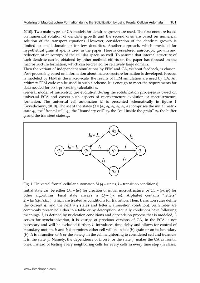
2010). Two main types of CA models for dendrite growth are used. The first ones are based on numerical solution of dendrite growth and the second ones are based on numerical solution of the transport equations. However, consideration of the dendrite growth is limited to small domain or for few dendrites. Another approach, which provided for hypothetical grain shape, is used in the paper. Here is considered anisotropic growth and reduction of anisotropy of the cellular space, as well. To assume that internal structure of each dendrite can be obtained by other method, efforts on the paper has focused on the macrostructure formation, which can be created for relatively large domain. Then the variant of independent simulations by FEM and CA, without feedback, is chosen. Post-processing based on information about macrostructure formation is developed. Process is modeled by FEM in the macro-scale; the results of FEM simulation are used by CA. An arbitrary FEM code can be used in such a scheme. It is enough to meet the requirements for data needed for post-processing calculations. General model of microstructure evolution during the solidification processes is based on universal FCA and covers such aspects of microstructure evolution or macrostructure formation. The universal cell automaton M is presented schematically in figure 1 (Svyetlichnyy, 2010). The set of the states Q = {q0, q1, q2, q3, qb, qt} comprises the initial matrix state q0, the “frontal cell” q1, the “boundary cell” q2, the “cell inside the grain” q3, the buffer qb and the transient states qt.
q3
qb
I3
qt It
q1 I1
I2
q0 I0∨ I4
q2
I4
I0∨ I4
Fig. 1. Universal frontal cellular automaton M (q – states, I – transition conditions)
Initial state can be either Qin = {q0} for creation of initial microstructure, or Qin = {q2, q3} for
other algorithms. Final state always is Qf = {q2, q3}. Alphabet contains “letters”
Σ = {I0,I1,I2,I3,I4,It}, which are treated as conditions for transition. Then, transition rules define
the current qi, and the next qi+1 states and letter Ik (transition condition). Such rules are
commonly presented either in a table or by description. Actually conditions have following
meanings. I0 is defined by nucleation conditions and depends on process that is modeled, It
serves for synchronization, it is vestige of previous versions of CA, in the FCA is not
necessary and will be excluded further, I1 introduces time delay and allows for control of
boundary motion, I2 and I3 determines either cell will be inside (I2) grain or on its boundary
(I3), I4 is a function of I1 or the state q1 in the cell neighboring to considered cell and transfers
it in the state qb. Namely, the dependence of I4 on I1 or the state q1 makes the CA as frontal
ones. Instead of testing every neighboring cells for every cells in every time step (in classic
www.intechopen.com
Cellular Automata - Innovative Modelling for Science and Engineering
182
CA) only cells in state q1 forms condition I4 for their neighbors (in FCA). “Language” of CA
consists of some “words”, which contain several letter and mean cell transition from initial
to final state. For example, four words (I0 ∨ I4)ItI1(I2 ∨ I3) define creation or formation micro-
or macrostructure.
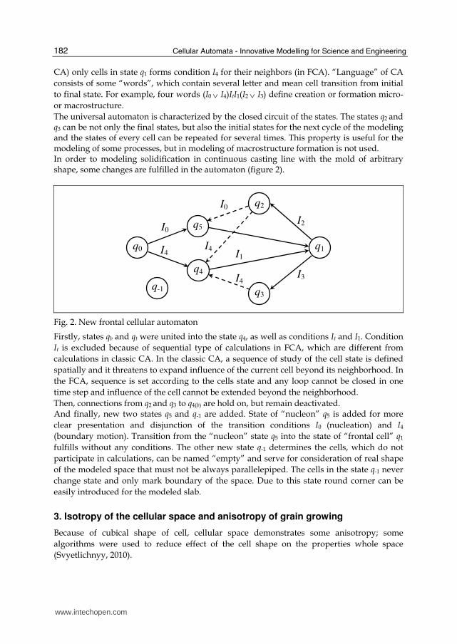
The universal automaton is characterized by the closed circuit of the states. The states q2 and q3 can be not only the final states, but also the initial states for the next cycle of the modeling and the states of every cell can be repeated for several times. This property is useful for the modeling of some processes, but in modeling of macrostructure formation is not used. In order to modeling solidification in continuous casting line with the mold of arbitrary shape, some changes are fulfilled in the automaton (figure 2).
q3
q4 I3
I1 q1
I2
q0
I0
q2
I4 q-1
q5
I0
I4 I4
Fig. 2. New frontal cellular automaton
Firstly, states qb and qt were united into the state q4, as well as conditions It and I1. Condition
It is excluded because of sequential type of calculations in FCA, which are different from
calculations in classic CA. In the classic CA, a sequence of study of the cell state is defined
spatially and it threatens to expand influence of the current cell beyond its neighborhood. In
the FCA, sequence is set according to the cells state and any loop cannot be closed in one
time step and influence of the cell cannot be extended beyond the neighborhood.
Then, connections from q2 and q3 to q4(b) are hold on, but remain deactivated. And finally, new two states q5 and q-1 are added. State of “nucleon” q5 is added for more
clear presentation and disjunction of the transition conditions I0 (nucleation) and I4
(boundary motion). Transition from the “nucleon” state q5 into the state of “frontal cell” q1
fulfills without any conditions. The other new state q-1 determines the cells, which do not
participate in calculations, can be named “empty” and serve for consideration of real shape
of the modeled space that must not be always parallelepiped. The cells in the state q-1 never
change state and only mark boundary of the space. Due to this state round corner can be
easily introduced for the modeled slab.
3. Isotropy of the cellular space and anisotropy of grain growing
Because of cubical shape of cell, cellular space demonstrates some anisotropy; some
algorithms were used to reduce effect of the cell shape on the properties whole space
(Svyetlichnyy, 2010).
www.intechopen.com
Modeling of Macrostructure Formation during the Solidification by using Frontal Cellular Automata
183
According to the scheme in figure 2, words (I0 ∨ I4I1)(I2 ∨ I3) with initial state q0 and final states
q2 and q3 are responsible for formation of macrostructure. Letter I0 describes nucleation; I4 is
appeared, when moving boundary of the growing grain has passed the neighboring cell.
Letters I0 and I4 set cell into the “nucleon” state q5 or “transient” state q4 respectively. The
transient state q4 introduces delay, which is the time needed for the motion of a grain
boundary through the cell with reckoning of cell shape and sizes. It defines grain growth rate,
which can be arbitrary function of direction of growing, normal to boundary, disorientation
angle or other parameters. Another effect of introduction of transient state is reduction of
anisotropy of the cellular space. After passing the front thru whole cell (delay in several steps),
the letter I1 appears, and the cell is transferred into the state q1. Cells pass from the “nucleon”
state q5 into the “frontal” state q1 at the end of the step without any delay. The letters I2 and I3
emerge when all cells in its von Neumann neighborhood are in the state of q1, q2 or q3. If all
neighboring cells belongs to the same grain, a new state of cell is the “inside grain” q3
otherwise “on the boundary” q2. States q3 and q2 are the final states of the algorithm.
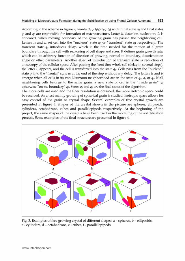
The more cells are used and the finer resolution is obtained, the more isotropic space could
be received. As a test mainly growing of spherical grain is studied. Isotropic space allows for
easy control of the grain or crystal shape. Several examples of free crystal growth are
presented in figure 3. Shapes of the crystal shown in the picture are spheres, ellipsoids,
cylinders, octahedrons, cubes and parallelepipeds respectively. At the beginning of the
project, the same shapes of the crystals have been tried in the modeling of the solidification
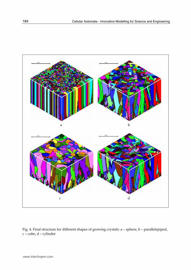
process. Some examples of the final structure are presented in figure 4.
a b c
d e f
Fig. 3. Examples of free growing crystal of different shapes: a – spheres, b – ellipsoids, c - cylinders, d – octahedrons, e - cubes, f - parallelepipeds
www.intechopen.com
Cellular Automata - Innovative Modelling for Science and Engineering
184
a b
c d
Fig. 4. Final structure for different shapes of growing crystals: a – sphere, b – parallelepiped, c – cube, d – cylinder
www.intechopen.com
Modeling of Macrostructure Formation during the Solidification by using Frontal Cellular Automata
185
a b
c d
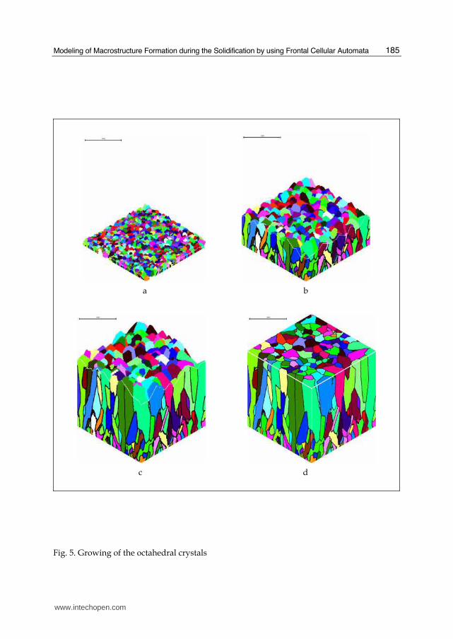
Fig. 5. Growing of the octahedral crystals
www.intechopen.com
Cellular Automata - Innovative Modelling for Science and Engineering
186
a b
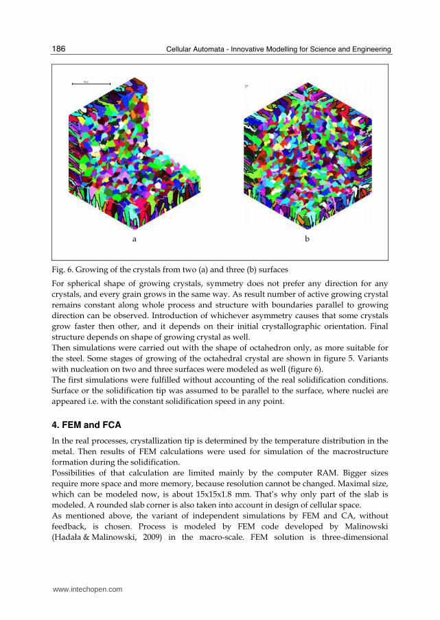
Fig. 6. Growing of the crystals from two (a) and three (b) surfaces
For spherical shape of growing crystals, symmetry does not prefer any direction for any
crystals, and every grain grows in the same way. As result number of active growing crystal
remains constant along whole process and structure with boundaries parallel to growing
direction can be observed. Introduction of whichever asymmetry causes that some crystals
grow faster then other, and it depends on their initial crystallographic orientation. Final
structure depends on shape of growing crystal as well.
Then simulations were carried out with the shape of octahedron only, as more suitable for
the steel. Some stages of growing of the octahedral crystal are shown in figure 5. Variants
with nucleation on two and three surfaces were modeled as well (figure 6).
The first simulations were fulfilled without accounting of the real solidification conditions.
Surface or the solidification tip was assumed to be parallel to the surface, where nuclei are
appeared i.e. with the constant solidification speed in any point.
4. FEM and FCA
In the real processes, crystallization tip is determined by the temperature distribution in the
metal. Then results of FEM calculations were used for simulation of the macrostructure
formation during the solidification.
Possibilities of that calculation are limited mainly by the computer RAM. Bigger sizes
require more space and more memory, because resolution cannot be changed. Maximal size,
which can be modeled now, is about 15x15x1.8 mm. That’s why only part of the slab is
modeled. A rounded slab corner is also taken into account in design of cellular space.
As mentioned above, the variant of independent simulations by FEM and CA, without
feedback, is chosen. Process is modeled by FEM code developed by Malinowski
(Hadała & Malinowski, 2009) in the macro-scale. FEM solution is three-dimensional
www.intechopen.com
Modeling of Macrostructure Formation during the Solidification by using Frontal Cellular Automata
187
stationary temperature distribution in the slab that moves with constant speed in
consideration of all constructive and technological conditions.
Two external files are used for communication between FEM and FCA. The first one carries
information about main parameters of modeled process, such as slab shape and sizes,
number of FEM elements, coordinates of the FEM mesh nodes, temperature of solidus and
liquidus, casting speed and so on. The second one contains temperature distribution. The
distribution has to be suited to the cellular space. Though FEM solution is stationary
temperature field, FCA considers the solution as hundreds locations of cross-section of the
slab along casting line. Instead of spatial coordinate along the slab, FCA uses time, taking
into account casting speed.
Every location of cross-section is studied before FCA calculations. Simulation of
macrostructure formation begins when temperature at least in the one FEM node, which
belongs to the point inside cellular space, decreases below the temperature of solidus.
When temperature drops below the temperature of solidus in whole cellular space, the
simulation is stopped. The simulation is carried out from one cross-section location to
other. It makes timing easy, because internal time step is not of absolute value, but
relative only in that case.
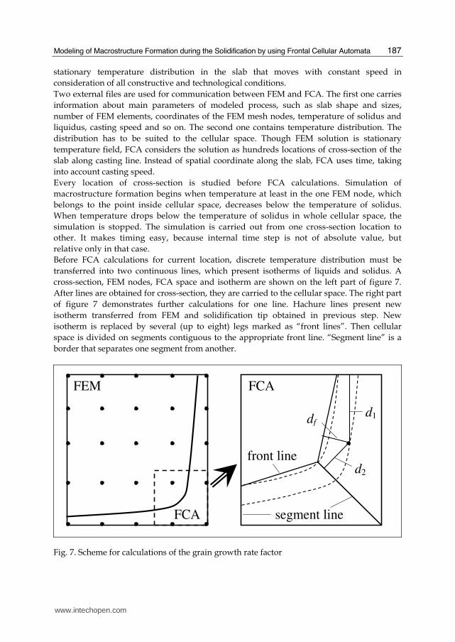
Before FCA calculations for current location, discrete temperature distribution must be
transferred into two continuous lines, which present isotherms of liquids and solidus. A
cross-section, FEM nodes, FCA space and isotherm are shown on the left part of figure 7.
After lines are obtained for cross-section, they are carried to the cellular space. The right part
of figure 7 demonstrates further calculations for one line. Hachure lines present new
isotherm transferred from FEM and solidification tip obtained in previous step. New
isotherm is replaced by several (up to eight) legs marked as “front lines”. Then cellular
space is divided on segments contiguous to the appropriate front line. “Segment line” is a
border that separates one segment from another.
FEM
FCA
FCA
front line
segment line
d1
d2
df
Fig. 7. Scheme for calculations of the grain growth rate factor
www.intechopen.com
Cellular Automata - Innovative Modelling for Science and Engineering
188
Segmentation of the cellular space is used to differentiate growing rate in different part of
the space. Growing rate is additionally controlled by introduction of factor, which depends
on location of a point in appropriate segment. The factor is not constant inside the segment,
but linear function of local relative coordinate x. Coordinate x is defined from the equation:
x = d1 / (d1 + d2) and can changes in diapason 0 to 1, where d1 and d2 – distance from the
point to segment lines. Because solidification tip must reach the next location determined by
front line simultaneously on all line length, growing rate must be depended on initial
distance of solidification tip from the front line. Thus, for every cells on the front of
solidification (in state q4) three distances df (from front line), d1 and d2 (from segment lines)
are calculated. It allows to obtain dependence of distance df on local coordinate x for every
segment. Generally obtained dependence for whole cellular space has discontinuities on the
border of segments; and the discontinuities must be eliminated. Then dependence is
normalized by division on maximal value (distance) and constrains on minimal value are
introduced. Such a transformation as a result gives a growing rate factor. New cells involved
in solidification process inherit from the neighboring cells number of segment, its local
coordinate is calculated, and time delay for the state q4 is computed in view of growing rate
factor correspondent to its location.
Calculations are finished for current location of cross-section when solidification tip reaches the front line. Then new location is chosen and calculations are repeated.
5. FCA code
Code for FCA modeling has been designed in Department of Heat Engineering and
Environment Protection, Faculty of Metal Engineering and Industrial Computer Science,
AGH University of Science and Technology (Poland). It is still developing now. Several
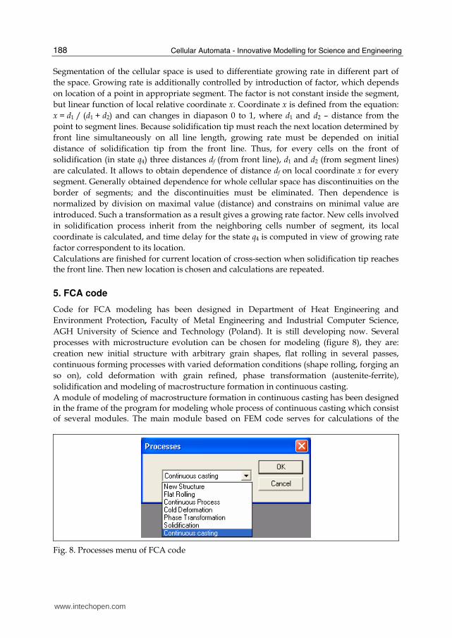
processes with microstructure evolution can be chosen for modeling (figure 8), they are:
creation new initial structure with arbitrary grain shapes, flat rolling in several passes,
continuous forming processes with varied deformation conditions (shape rolling, forging an
so on), cold deformation with grain refined, phase transformation (austenite-ferrite),
solidification and modeling of macrostructure formation in continuous casting.
A module of modeling of macrostructure formation in continuous casting has been designed in the frame of the program for modeling whole process of continuous casting which consist of several modules. The main module based on FEM code serves for calculations of the
Fig. 8. Processes menu of FCA code
www.intechopen.com
Modeling of Macrostructure Formation during the Solidification by using Frontal Cellular Automata
189
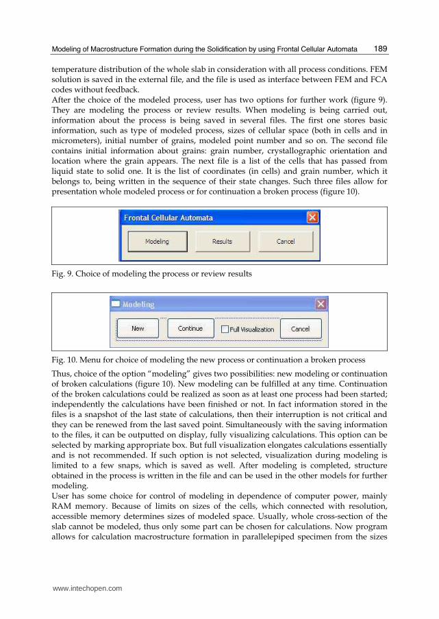
temperature distribution of the whole slab in consideration with all process conditions. FEM solution is saved in the external file, and the file is used as interface between FEM and FCA codes without feedback. After the choice of the modeled process, user has two options for further work (figure 9). They are modeling the process or review results. When modeling is being carried out, information about the process is being saved in several files. The first one stores basic information, such as type of modeled process, sizes of cellular space (both in cells and in micrometers), initial number of grains, modeled point number and so on. The second file contains initial information about grains: grain number, crystallographic orientation and location where the grain appears. The next file is a list of the cells that has passed from liquid state to solid one. It is the list of coordinates (in cells) and grain number, which it belongs to, being written in the sequence of their state changes. Such three files allow for presentation whole modeled process or for continuation a broken process (figure 10).
Fig. 9. Choice of modeling the process or review results
Fig. 10. Menu for choice of modeling the new process or continuation a broken process
Thus, choice of the option “modeling” gives two possibilities: new modeling or continuation of broken calculations (figure 10). New modeling can be fulfilled at any time. Continuation of the broken calculations could be realized as soon as at least one process had been started; independently the calculations have been finished or not. In fact information stored in the files is a snapshot of the last state of calculations, then their interruption is not critical and they can be renewed from the last saved point. Simultaneously with the saving information to the files, it can be outputted on display, fully visualizing calculations. This option can be selected by marking appropriate box. But full visualization elongates calculations essentially and is not recommended. If such option is not selected, visualization during modeling is limited to a few snaps, which is saved as well. After modeling is completed, structure obtained in the process is written in the file and can be used in the other models for further modeling. User has some choice for control of modeling in dependence of computer power, mainly RAM memory. Because of limits on sizes of the cells, which connected with resolution, accessible memory determines sizes of modeled space. Usually, whole cross-section of the slab cannot be modeled, thus only some part can be chosen for calculations. Now program allows for calculation macrostructure formation in parallelepiped specimen from the sizes
www.intechopen.com
Cellular Automata - Innovative Modelling for Science and Engineering
190
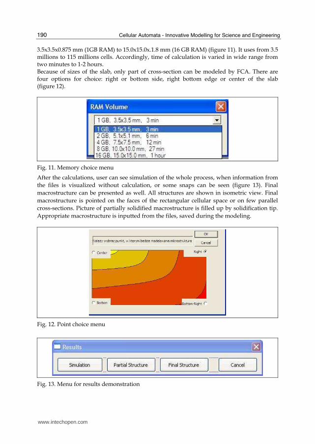
3.5x3.5x0.875 mm (1GB RAM) to 15.0x15.0x.1.8 mm (16 GB RAM) (figure 11). It uses from 3.5 millions to 115 millions cells. Accordingly, time of calculation is varied in wide range from two minutes to 1-2 hours. Because of sizes of the slab, only part of cross-section can be modeled by FCA. There are four options for choice: right or bottom side, right bottom edge or center of the slab (figure 12).
Fig. 11. Memory choice menu
After the calculations, user can see simulation of the whole process, when information from
the files is visualized without calculation, or some snaps can be seen (figure 13). Final
macrostructure can be presented as well. All structures are shown in isometric view. Final
macrostructure is pointed on the faces of the rectangular cellular space or on few parallel
cross-sections. Picture of partially solidified macrostructure is filled up by solidification tip.
Appropriate macrostructure is inputted from the files, saved during the modeling.
Fig. 12. Point choice menu
Fig. 13. Menu for results demonstration
www.intechopen.com
Modeling of Macrostructure Formation during the Solidification by using Frontal Cellular Automata
191
6. Results
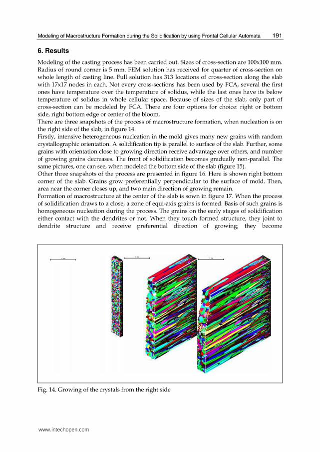
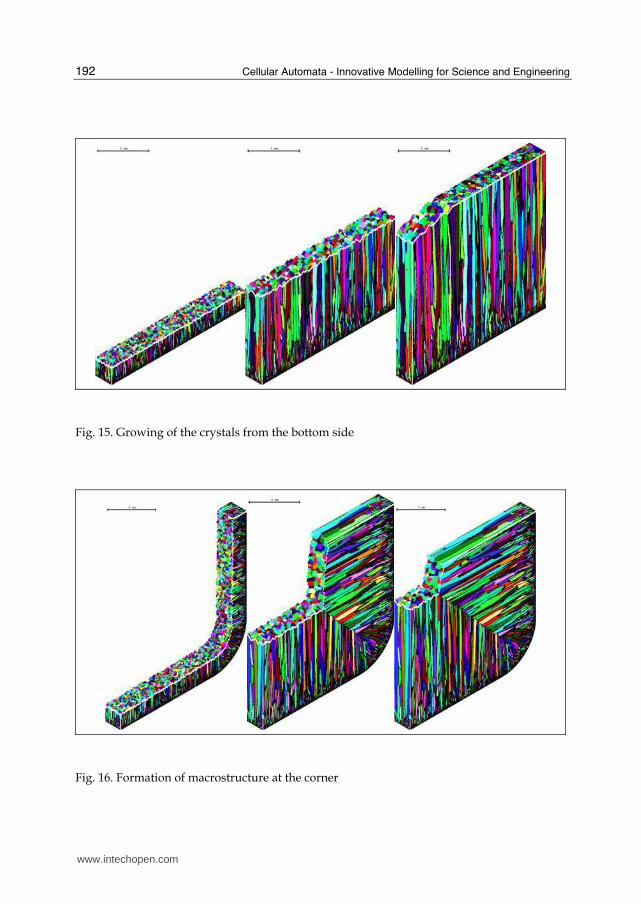
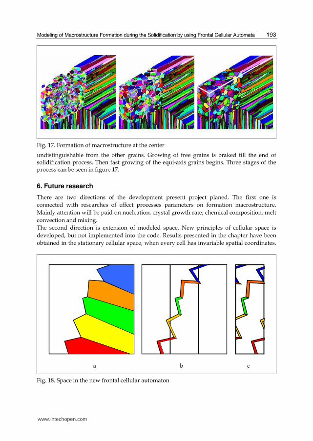
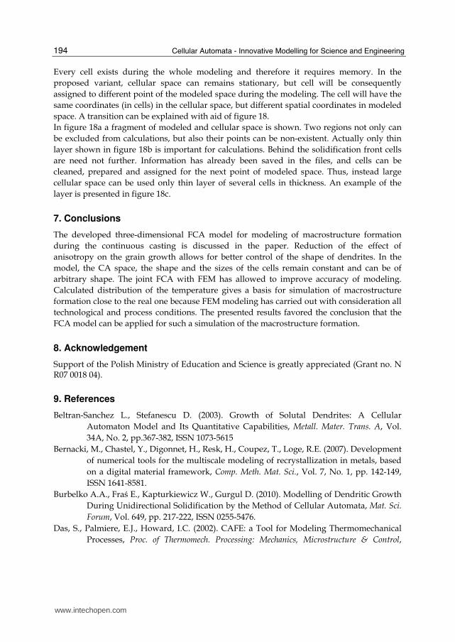
Modeling of the casting process has been carried out. Sizes of cross-section are 100x100 mm. Radius of round corner is 5 mm. FEM solution has received for quarter of cross-section on whole length of casting line. Full solution has 313 locations of cross-section along the slab with 17x17 nodes in each. Not every cross-sections has been used by FCA, several the first ones have temperature over the temperature of solidus, while the last ones have its below temperature of solidus in whole cellular space. Because of sizes of the slab, only part of cross-section can be modeled by FCA. There are four options for choice: right or bottom side, right bottom edge or center of the bloom. There are three snapshots of the process of macrostructure formation, when nucleation is on the right side of the slab, in figure 14. Firstly, intensive heterogeneous nucleation in the mold gives many new grains with random crystallographic orientation. A solidification tip is parallel to surface of the slab. Further, some grains with orientation close to growing direction receive advantage over others, and number of growing grains decreases. The front of solidification becomes gradually non-parallel. The same pictures, one can see, when modeled the bottom side of the slab (figure 15). Other three snapshots of the process are presented in figure 16. Here is shown right bottom corner of the slab. Grains grow preferentially perpendicular to the surface of mold. Then, area near the corner closes up, and two main direction of growing remain. Formation of macrostructure at the center of the slab is sown in figure 17. When the process of solidification draws to a close, a zone of equi-axis grains is formed. Basis of such grains is homogeneous nucleation during the process. The grains on the early stages of solidification either contact with the dendrites or not. When they touch formed structure, they joint to dendrite structure and receive preferential direction of growing; they become
Fig. 14. Growing of the crystals from the right side
www.intechopen.com
Cellular Automata - Innovative Modelling for Science and Engineering
192
Fig. 15. Growing of the crystals from the bottom side
Fig. 16. Formation of macrostructure at the corner
www.intechopen.com
Modeling of Macrostructure Formation during the Solidification by using Frontal Cellular Automata
193
Fig. 17. Formation of macrostructure at the center
undistinguishable from the other grains. Growing of free grains is braked till the end of solidification process. Then fast growing of the equi-axis grains begins. Three stages of the process can be seen in figure 17.
6. Future research
There are two directions of the development present project planed. The first one is
connected with researches of effect processes parameters on formation macrostructure.
Mainly attention will be paid on nucleation, crystal growth rate, chemical composition, melt
convection and mixing.
The second direction is extension of modeled space. New principles of cellular space is
developed, but not implemented into the code. Results presented in the chapter have been
obtained in the stationary cellular space, when every cell has invariable spatial coordinates.
a b c
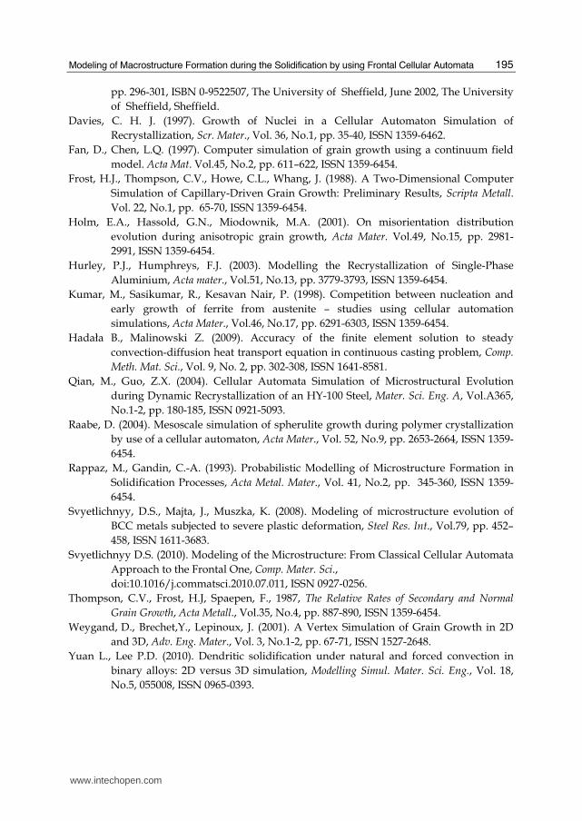
Fig. 18. Space in the new frontal cellular automaton
www.intechopen.com
Cellular Automata - Innovative Modelling for Science and Engineering
194
Every cell exists during the whole modeling and therefore it requires memory. In the
proposed variant, cellular space can remains stationary, but cell will be consequently
assigned to different point of the modeled space during the modeling. The cell will have the
same coordinates (in cells) in the cellular space, but different spatial coordinates in modeled
space. A transition can be explained with aid of figure 18.
In figure 18a a fragment of modeled and cellular space is shown. Two regions not only can
be excluded from calculations, but also their points can be non-existent. Actually only thin
layer shown in figure 18b is important for calculations. Behind the solidification front cells
are need not further. Information has already been saved in the files, and cells can be
cleaned, prepared and assigned for the next point of modeled space. Thus, instead large
cellular space can be used only thin layer of several cells in thickness. An example of the
layer is presented in figure 18c.
7. Conclusions
The developed three-dimensional FCA model for modeling of macrostructure formation
during the continuous casting is discussed in the paper. Reduction of the effect of
anisotropy on the grain growth allows for better control of the shape of dendrites. In the
model, the CA space, the shape and the sizes of the cells remain constant and can be of
arbitrary shape. The joint FCA with FEM has allowed to improve accuracy of modeling.
Calculated distribution of the temperature gives a basis for simulation of macrostructure
formation close to the real one because FEM modeling has carried out with consideration all
technological and process conditions. The presented results favored the conclusion that the
FCA model can be applied for such a simulation of the macrostructure formation.
8. Acknowledgement
Support of the Polish Ministry of Education and Science is greatly appreciated (Grant no. N R07 0018 04).
9. References
Beltran-Sanchez L., Stefanescu D. (2003). Growth of Solutal Dendrites: A Cellular
Automaton Model and Its Quantitative Capabilities, Metall. Mater. Trans. A, Vol.
34A, No. 2, pp.367-382, ISSN 1073-5615
Bernacki, M., Chastel, Y., Digonnet, H., Resk, H., Coupez, T., Loge, R.E. (2007). Development
of numerical tools for the multiscale modeling of recrystallization in metals, based
on a digital material framework, Comp. Meth. Mat. Sci., Vol. 7, No. 1, pp. 142-149,
ISSN 1641-8581.
Burbelko A.A., Fraś E., Kapturkiewicz W., Gurgul D. (2010). Modelling of Dendritic Growth
During Unidirectional Solidification by the Method of Cellular Automata, Mat. Sci.
Forum, Vol. 649, pp. 217-222, ISSN 0255-5476.
Das, S., Palmiere, E.J., Howard, I.C. (2002). CAFE: a Tool for Modeling Thermomechanical
Processes, Proc. of Thermomech. Processing: Mechanics, Microstructure & Control,
www.intechopen.com
Modeling of Macrostructure Formation during the Solidification by using Frontal Cellular Automata
195
pp. 296-301, ISBN 0-9522507, The University of Sheffield, June 2002, The University
of Sheffield, Sheffield.
Davies, C. H. J. (1997). Growth of Nuclei in a Cellular Automaton Simulation of
Recrystallization, Scr. Mater., Vol. 36, No.1, pp. 35-40, ISSN 1359-6462.
Fan, D., Chen, L.Q. (1997). Computer simulation of grain growth using a continuum field
model. Acta Mat. Vol.45, No.2, pp. 611–622, ISSN 1359-6454.
Frost, H.J., Thompson, C.V., Howe, C.L., Whang, J. (1988). A Two-Dimensional Computer
Simulation of Capillary-Driven Grain Growth: Preliminary Results, Scripta Metall.
Vol. 22, No.1, pp. 65-70, ISSN 1359-6454.
Holm, E.A., Hassold, G.N., Miodownik, M.A. (2001). On misorientation distribution
evolution during anisotropic grain growth, Acta Mater. Vol.49, No.15, pp. 2981-
2991, ISSN 1359-6454.
Hurley, P.J., Humphreys, F.J. (2003). Modelling the Recrystallization of Single-Phase
Aluminium, Acta mater., Vol.51, No.13, pp. 3779-3793, ISSN 1359-6454.
Kumar, M., Sasikumar, R., Kesavan Nair, P. (1998). Competition between nucleation and
early growth of ferrite from austenite – studies using cellular automation
simulations, Acta Mater., Vol.46, No.17, pp. 6291-6303, ISSN 1359-6454.
Hadała B., Malinowski Z. (2009). Accuracy of the finite element solution to steady
convection-diffusion heat transport equation in continuous casting problem, Comp.
Meth. Mat. Sci., Vol. 9, No. 2, pp. 302-308, ISSN 1641-8581.
Qian, M., Guo, Z.X. (2004). Cellular Automata Simulation of Microstructural Evolution
during Dynamic Recrystallization of an HY-100 Steel, Mater. Sci. Eng. A, Vol.A365,
No.1-2, pp. 180-185, ISSN 0921-5093.
Raabe, D. (2004). Mesoscale simulation of spherulite growth during polymer crystallization
by use of a cellular automaton, Acta Mater., Vol. 52, No.9, pp. 2653-2664, ISSN 1359-
6454.
Rappaz, M., Gandin, C.-A. (1993). Probabilistic Modelling of Microstructure Formation in
Solidification Processes, Acta Metal. Mater., Vol. 41, No.2, pp. 345-360, ISSN 1359-
6454.
Svyetlichnyy, D.S., Majta, J., Muszka, K. (2008). Modeling of microstructure evolution of
BCC metals subjected to severe plastic deformation, Steel Res. Int., Vol.79, pp. 452–
458, ISSN 1611-3683.
Svyetlichnyy D.S. (2010). Modeling of the Microstructure: From Classical Cellular Automata
Approach to the Frontal One, Comp. Mater. Sci.,
doi:10.1016/j.commatsci.2010.07.011, ISSN 0927-0256.
Thompson, C.V., Frost, H.J, Spaepen, F., 1987, The Relative Rates of Secondary and Normal
Grain Growth, Acta Metall., Vol.35, No.4, pp. 887-890, ISSN 1359-6454.
Weygand, D., Brechet,Y., Lepinoux, J. (2001). A Vertex Simulation of Grain Growth in 2D
and 3D, Adv. Eng. Mater., Vol. 3, No.1-2, pp. 67-71, ISSN 1527-2648.
Yuan L., Lee P.D. (2010). Dendritic solidification under natural and forced convection in
binary alloys: 2D versus 3D simulation, Modelling Simul. Mater. Sci. Eng., Vol. 18,
No.5, 055008, ISSN 0965-0393.
www.intechopen.com

Cellular Automata - Innovative Modelling for Science and Engineering
196
Zhu M.F., Hong C.P. (2001). A Modified Cellular Automaton Model for the Simulation of
Dendritic Growth in Solidification of Alloys, ISIJ Int., Vol. 41, No. 5, pp 436-445,
ISSN 0915-1559.
www.intechopen.com
Cellular Automata - Innovative Modelling for Science andEngineeringEdited by Dr. Alejandro Salcido
ISBN 978-953-307-172-5Hard cover, 426 pagesPublisher InTechPublished online 11, April, 2011Published in print edition April, 2011
InTech EuropeUniversity Campus STeP Ri Slavka Krautzeka 83/A 51000 Rijeka, Croatia Phone: +385 (51) 770 447 Fax: +385 (51) 686 166www.intechopen.com
InTech ChinaUnit 405, Office Block, Hotel Equatorial Shanghai No.65, Yan An Road (West), Shanghai, 200040, China
Phone: +86-21-62489820 Fax: +86-21-62489821
Modelling and simulation are disciplines of major importance for science and engineering. There is no sciencewithout models, and simulation has nowadays become a very useful tool, sometimes unavoidable, fordevelopment of both science and engineering. The main attractive feature of cellular automata is that, in spiteof their conceptual simplicity which allows an easiness of implementation for computer simulation, as a detailedand complete mathematical analysis in principle, they are able to exhibit a wide variety of amazingly complexbehaviour. This feature of cellular automata has attracted the researchers' attention from a wide variety ofdivergent fields of the exact disciplines of science and engineering, but also of the social sciences, andsometimes beyond. The collective complex behaviour of numerous systems, which emerge from theinteraction of a multitude of simple individuals, is being conveniently modelled and simulated with cellularautomata for very different purposes. In this book, a number of innovative applications of cellular automatamodels in the fields of Quantum Computing, Materials Science, Cryptography and Coding, and Robotics andImage Processing are presented.
How to referenceIn order to correctly reference this scholarly work, feel free to copy and paste the following:
Dmytro S. Svyetlichnyy (2011). Modeling of Macrostructure Formation during the Solidification by using FrontalCellular Automata, Cellular Automata - Innovative Modelling for Science and Engineering, Dr. AlejandroSalcido (Ed.), ISBN: 978-953-307-172-5, InTech, Available from: http://www.intechopen.com/books/cellular-automata-innovative-modelling-for-science-and-engineering/modeling-of-macrostructure-formation-during-the-solidification-by-using-frontal-cellular-automata

© 2011 The Author(s). Licensee IntechOpen. This chapter is distributedunder the terms of the Creative Commons Attribution-NonCommercial-ShareAlike-3.0 License, which permits use, distribution and reproduction fornon-commercial purposes, provided the original is properly cited andderivative works building on this content are distributed under the samelicense.