Embed Size (px)
Citation preview
ISIJ International, Vol. 57 (2017), No. 11
© 2017 ISIJ1971
ISIJ International, Vol. 57 (2017), No. 11, pp. 1971–1979
* Corresponding author: E-mail: [email protected]: http://dx.doi.org/10.2355/isijinternational.ISIJINT-2016-710
1. Introduction
High quality constraints demand the development of steel with increasingly stringent cleanliness levels. Metallurgical operations can be optimized to improve the cleanliness of molten steel with respect to metal treatment in the ladle, tundish and mold. For example, the ladle metallurgy fur-nace is fully responsible for the process of alloy composi-tion and temperature homogenization, desulphurization and inclusion removal.1–4) Slag layer plays a crucial role in the refining of molten steel in ladle metallurgy; it can promote the desulfurization reaction, prevent the secondary oxida-tion of steel, and reduce the heat dissipation. In order to enhance the slag-metal reactions and promote the floatation of non-metallic inclusions, argon gas is usually injected into the molten steel bath through one or a number of bottom porous plugs. The resulting column of bubbles rises due to the buoyancy and leaves the molten steel bath through the free surface at the top. The upwelling flow from the gas-liquid plume turns horizontally at the free surface and pushes the slag layer to the periphery of the ladle. If the thickness of slag layer is sufficiently thin, an open area of molten steel would be exposed to the atmosphere, which is usually called the “slag eye”, as shown in Fig. 1.
Modeling of Gas-Steel-Slag Three-Phase Flow in Ladle Metallurgy: Part I. Physical Modeling
Zhongqiu LIU,* Linmin LI and Baokuan LI
School of Metallurgy, Northeastern University, Shenyang, 110819 China.
(Received on December 6, 2016; accepted on June 27, 2017)
To obtain a better understanding the gas-steel-slag three-phase flow in ladle metallurgy with eccentric gas bubbling, both the single-plug-stirred and dual-plug-stirred water model systems were employed. The plume Froude number derived from the buoyancy of the bubble plume was used to characterize the plume two-phase flow. The elctrical conductivity measurement technique was applied to measure the mixing time. A video technique was used to monitor the slag eye and the open software called ImageJ was taken to quantify the slag eye area. Some experiments were carried out to determine the location of the probe in the ladle where the measured mixing times can be interpreted as the bulk mixing times. The eccentric gas injection in the ladle bottom can improve the mixing efficiency in the ladle. Shorter mixing times can be achieved by injecting gas through two porous plugs, located diametrically opposite at mid-bath radius position (α=180°). A critical gas flow rate is proposed based on the formation of slag eye. The mixing time will decreases sharply at the condition of slag eye formation and collapse alternately. The critical gas flow rate increases with increasing the slag layer thickness and decreasing the porous plug angles. Four fators effect on the slag eye area were investigated: the gas flow rate, slag layer thickness, porous plug locations and angles. A semi-empirical model was developed based on the experimental data of the present work to describe the slag eye area as a function of the heights of the two liquids and the gas flow rate. The present correlation for slag eye area was reviewed against many previous different liquid-liquid systems.
KEY WORDS: three-phase flow; mixing time; slag eye area; ladle metallurgy; eccentric gas bubbling.
The formation of slag eye is important in ladle metal-lurgy, because the eye is a site for oxygen and nitrogen pickup, and the refining reactions with the slag are limited to the slag-metal contact area. It has been suggested that good slag-metal contact around the slag eye makes higher slag-metal reaction and desulphurization rate, comparing with an induction stirred ladle.5) Extensive studies of the slag eye formation in the gas-stirred ladle have been performed
Fig. 1. Transient slag eye phenomena in actual ladle metallurgy. (Online version in color.)
ISIJ International, Vol. 57 (2017), No. 11
© 2017 ISIJ 1972
on the physical modeling. Yonezawa and Schwerdtfeger2,6,7) carried out cold model experiments on studying the sizes of slag eyes using mercury and silicon oil as metal and slag, respectively. The time-averaged slag eye area has been rep-resented in the form of non-dimensional correlations. And some plant experiments on a 350 t ladle were also performed in their article and the results meet the non-dimensional cor-relations well. Then they studied the dynamics of the spout of gas plumes discharging from a melt. A nondimensional spout height has been defined, which is independent of the Froude number and of the nondimensional nozzle diame-ter.7) Later, Iguchi et al.8) proposed an empirical equation for spout eye area in ladle refining process, which adequately includes many parameters such as the physical properties of gas and liquids. Subagyo et al.3) developed an alternative correlation based on the experimental data of Yonezawa and Schwerdtfeger,2,6) introducing a new dimensionless variable. They claimed that this correlation for the slag eye area can approximate the measured values and can unify the plant and cold model data. Mazumdar and Evans9) also proposed a dimensionless plume eye exposed area to estimate the eye area during ladle gas injection operation, which is a function of the fractional slag depth and the Froude num-ber. Krishnapisharody and Irons10) developed a mechanistic model for eye size from fundamental fluid flow consider-ations. The model expressed a dimensionless eye area in terms of a density ratio of the fluids and a Froude number. Then they proposed a new model for the slag eye,11) which is an extension to the previous one, where the eye size was computed from the primary operating variables of the ladle and demonstrated reliable predictive abilities in a variety of multi-phase systems. Peranandhanthan and Mazumdar12) developed a new polynomial correlation for slag eye area, in which the dimensionless slag eye area can be expressed in terms of Froude number, density ratio, and Reynolds number. Recently, Krishnapisharody and Irons13) proposed a new model for slag eyes in the ladles covered with thick slag, indicating that the eyes formed can be smaller than the spout region when the slag layer is sufficiently thick. In addition, many research works for slag eye formation have been carried out by other workers.14,15) However, relatively little work has been reported on slag eye formation in ladle metallurgy with eccentric and multi- plugs gas bubbling.
The efficiency of many chemical processing operations carried out in the ladle metallurgy is much related to mix-ing phenomena. Mixing time, which represents the intensity of mixing inside the fluid in the reactor, has been widely used to describe and characterize the mixing phenomena quantitatively. Another critical issue in gas-stirred ladle metallurgy is the mixing time in the molten steel. Joo and Guthrie16) studied the mixing phenomena in a ladle using water model experiment, which indicates mixing behavior as a function of plug location and number, tracer addi-tion point and probe location. Shorter mixing time can be achieved by injecting gas through twin porous plugs located diametrically opposite at midbath radius position. However, compared with single porous plugs configuration, the twin porous plugs configuration ensures relatively faster mixing only at moderately higher gas injection rates. Later, Zhu et al.17) proposed an empirical correlation for estimating 95 pct. mixing times in the ladle operated with multiple
porous plugs according to τ εmix m N= −8 52 0 33 0 33. . . , which indicates that at an equivalent specific potential energy input rate, εm, any increase in the number of porous plugs, N, is likely to lead to a corresponding increase in mixing times. Mandal et al.18) carried out similar investigations on ladles with dual porous plugs. A dimensional analysis shows that mixing times could be reasonably described via τmix=15Q −0.38L −0.56R2.0, in which L is the depth of melt, R is the vessel radius, and Q is the ambient flow rate. The salt solution tracer together with the conductivity method has become more and more popular nowadays. However, many researchers19–21) have demonstrated the mixing time was indeed depending on the location of probe and tracer injection. Recently, Chen et al.21) studied the effect of salt tracer amount on the mixing time, which proposes that the tracer selection should be considered combined with the criterion of the definition of mixing. In addition, Conejo et al.22,23) reported the effects of slag properties (thickness and viscosity) and nozzle diameter on mixing phenomena in gas-stirred ladles by physical modeling, a negative effect of both slag thickness and slag viscosity on mixing time was found, and an increase in nozzle diameter decreases mixing time, but the effect is not significant. However, relatively little work has been reported on the effect of slag eye forma-tion on the mixing time in ladle metallurgy.
The present study aims at obtaining a better understand-ing of the mixing time and slag eye formation in ladle metallurgy with eccentric single and dual porous plugs gas bubbling. A one-third scale water model is employed to study the mixing time and slag eye formation in a gas-stirred ladle, considering four factors effects: gas flow rate, slag layer thickness, single porous plug location, and dual porous plugs angle. A critical gas flow rate is proposed based on the formation of slag eye. Two semi-empirical models for the slag eye area in the ladle are presented based on the non-dimensional model.
2. Experimental Procedure
2.1. Experimental SystemIn order to measure the mixing time and slag eye area
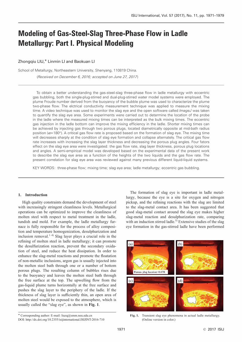
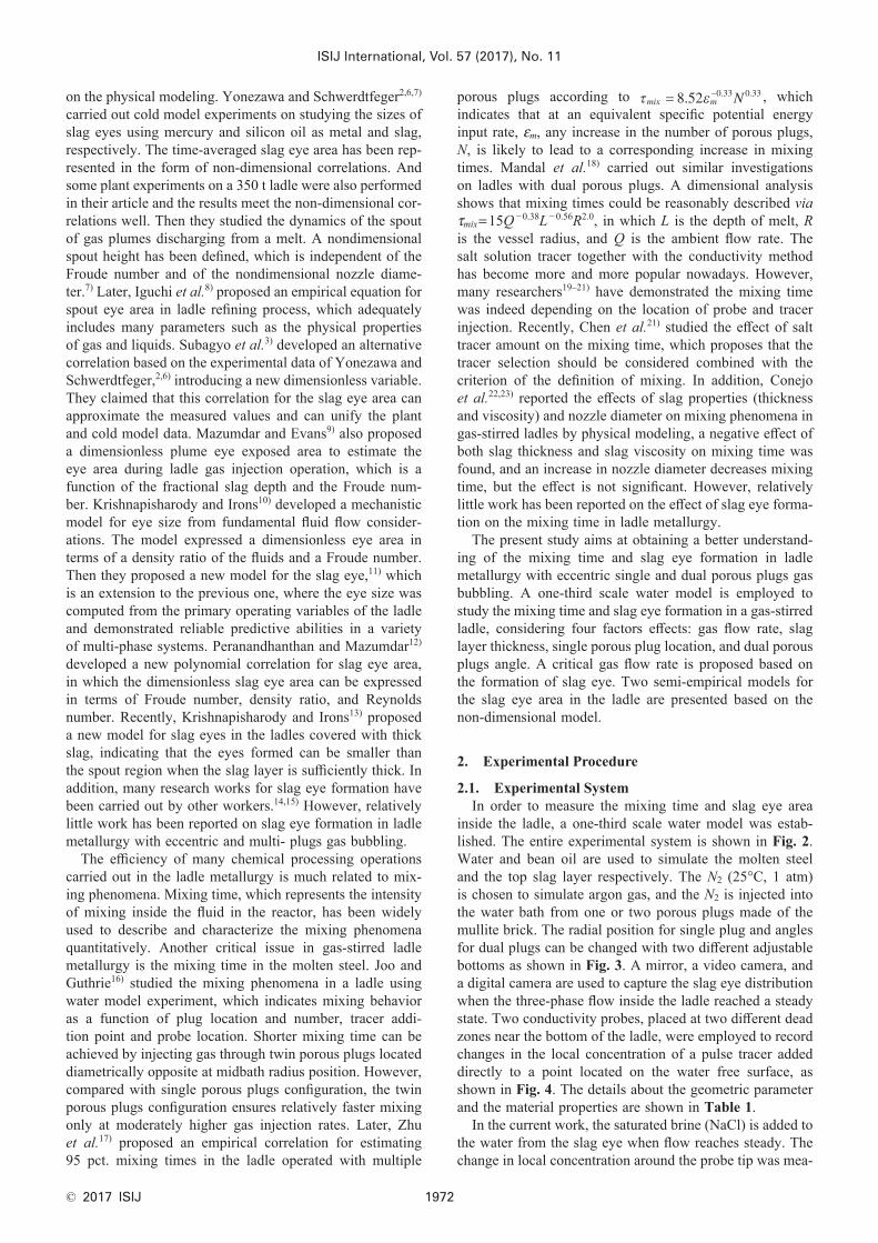
inside the ladle, a one-third scale water model was estab-lished. The entire experimental system is shown in Fig. 2. Water and bean oil are used to simulate the molten steel and the top slag layer respectively. The N2 (25°C, 1 atm) is chosen to simulate argon gas, and the N2 is injected into the water bath from one or two porous plugs made of the mullite brick. The radial position for single plug and angles for dual plugs can be changed with two different adjustable bottoms as shown in Fig. 3. A mirror, a video camera, and a digital camera are used to capture the slag eye distribution when the three-phase flow inside the ladle reached a steady state. Two conductivity probes, placed at two different dead zones near the bottom of the ladle, were employed to record changes in the local concentration of a pulse tracer added directly to a point located on the water free surface, as shown in Fig. 4. The details about the geometric parameter and the material properties are shown in Table 1.
In the current work, the saturated brine (NaCl) is added to the water from the slag eye when flow reaches steady. The change in local concentration around the probe tip was mea-
ISIJ International, Vol. 57 (2017), No. 11
© 2017 ISIJ1973
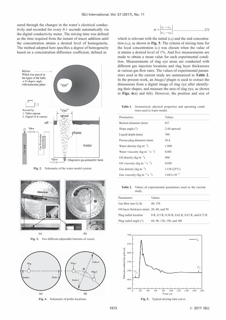
sured through the changes in the water’s electrical conduc-tivity and recorded for every 0.1 seconds automatically via the digital conductivity meter. The mixing time was defined as the time required from the instant of tracer addition until the concentration attains a desired level of homogeneity. The method adopted here specifies a degree of homogeneity based on a concentration difference coefficient, defined as
α =−−
∞
∞
c c
c ct
0
................................ (1)
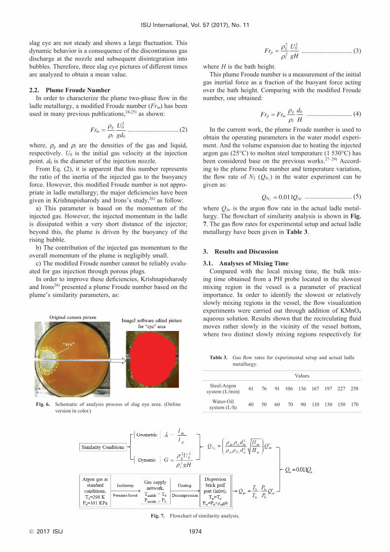
which is relevant with the initial (c0) and the end concentra-tion (c0), as shown in Fig. 5. The criteria of mixing time for the local concentration (ct) was chosen when the value of α attains a desired level of 1%. And five measurements are made to obtain a mean value for each experimental condi-tion. Measurements of slag eye areas are conducted with different gas injection locations and slag layer thicknesses at various gas flow rates. The values of experimental param-eters used in the current study are summarized in Table 2. In the present work, an ImageJ plugin is used to extract the dimensions from a digital image of slag eye after identify-ing their shapes, and measure the area of slag eye, as shown in Figs. 6(a) and 6(b). However, the position and size of
Table 2. Values of experimental parameters used in the current study.
Parameters Values
Gas flow rate (L/h) 40–170
Oil layer thickness (mm) 20, 40, and 50
Plug radial location 0 R, 0.5 R, 0.56 R, 0.62 R, 0.67 R, and 0.73 R
Plug radial angle (°) 60, 90, 120, 150, and 180
Table 1. Geometrical, physical properties and operating condi-tions used in water model.
Parameters Values
Bottom diameter (mm) 617
Slope angle (°) 2.44 upward
Liquid depth (mm) 700
Porous plug diameter (mm) 43.4
Water density (kg·m −3) 1 000
Water viscosity (kg·m −1·s −1) 0.001
Oil density (kg·m −3) 900
Oil viscosity (kg·m −1·s −1) 0.058
Gas density (kg·m −3) 1.138 (25°C)
Gas viscosity (kg·m −1·s −1) 1.663×10 − 5
Fig. 2. Schematic of the water model system.
Fig. 3. Two different adjustable bottoms of vessel.
Fig. 4. Schematic of probe locations. Fig. 5. Typical mixing time curve.
ISIJ International, Vol. 57 (2017), No. 11
© 2017 ISIJ 1974
slag eye are not steady and shows a large fluctuation. This dynamic behavior is a consequence of the discontinuous gas discharge at the nozzle and subsequent disintegration into bubbles. Therefore, three slag eye pictures of different times are analyzed to obtain a mean value.
2.2. Plume Froude NumberIn order to characterize the plume two-phase flow in the
ladle metallurgy, a modified Froude number (Frm) has been used in many previous publications,24,25) as shown:
FrU
gdm
g
l
=ρρ
02
0
............................... (2)
where, ρg and ρl are the densities of the gas and liquid, respectively. U0 is the initial gas velocity at the injection point. d0 is the diameter of the injection nozzle.
From Eq. (2), it is apparent that this number represents the ratio of the inertia of the injected gas to the buoyancy force. However, this modified Froude number is not appro-priate in ladle metallurgy; the major deficiencies have been given in Krishnapisharody and Irons’s study,26) as follow:
a) This parameter is based on the momentum of the injected gas. However, the injected momentum in the ladle is dissipated within a very short distance of the injector; beyond this, the plume is driven by the buoyancy of the rising bubble.
b) The contribution of the injected gas momentum to the overall momentum of the plume is negligibly small.
c) The modified Froude number cannot be reliably evalu-ated for gas injection through porous plugs.
In order to improve these deficiencies, Krishnapisharody and Irons26) presented a plume Froude number based on the plume’s similarity parameters, as:
FrU
gHp
g
l
=ρρ
2
2
02
............................... (3)
where H is the bath height.This plume Froude number is a measurement of the initial
gas inertial force as a fraction of the buoyant force acting over the bath height. Comparing with the modified Froude number, one obtained:
Fr Frd
Hp m
g
l
=ρρ
0 ............................ (4)
In the current work, the plume Froude number is used to obtain the operating parameters in the water model experi-ment. And the volume expansion due to heating the injected argon gas (25°C) to molten steel temperature (1 530°C) has been considered base on the previous works.27–29) Accord-ing to the plume Froude number and temperature variation, the flow rate of N2 (QN2) in the water experiment can be given as:
Q QN Ar2 0 011= . ............................. (5)
where QAr is the argon flow rate in the actual ladle metal-lurgy. The flowchart of similarity analysis is shown in Fig. 7. The gas flow rates for experimental setup and actual ladle metallurgy have been given in Table 3.
3. Results and Discussion
3.1. Analyses of Mixing TimeCompared with the local mixing time, the bulk mix-
ing time obtained from a PH probe located in the slowest mixing region in the vessel is a parameter of practical importance. In order to identify the slowest or relatively slowly mixing regions in the vessel, the flow visualization experiments were carried out through addition of KMnO4
aqueous solution. Results shown that the recirculating fluid moves rather slowly in the vicinity of the vessel bottom, where two distinct slowly mixing regions respectively for
Fig. 6. Schematic of analysis process of slag eye area. (Online version in color.)
Table 3. Gas flow rates for experimental setup and actual ladle metallurgy.
Values
Steel-Argon system (L/min) 61 76 91 106 136 167 197 227 258
Water-Oil system (L/h) 40 50 60 70 90 110 130 150 170
Fig. 7. Flowchart of similarity analysis.
ISIJ International, Vol. 57 (2017), No. 11
© 2017 ISIJ1975
single-plug and dual-plug ladle were marked by “probe-1, closer to porous plugs” and “probe-2, far away from porous plugs”, as shown in Fig. 4.
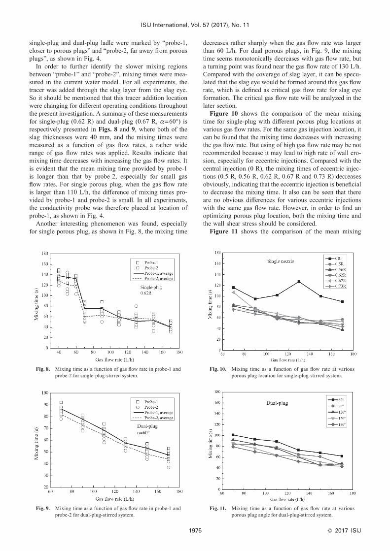
In order to further identify the slower mixing regions between “probe-1” and “probe-2”, mixing times were mea-sured in the current water model. For all experiments, the tracer was added through the slag layer from the slag eye. So it should be mentioned that this tracer addition location were changing for different operating conditions throughout the present investigation. A summary of these measurements for single-plug (0.62 R) and dual-plug (0.67 R, α=60°) is respectively presented in Figs. 8 and 9, where both of the slag thicknesses were 40 mm, and the mixing times were measured as a function of gas flow rates, a rather wide range of gas flow rates was applied. Results indicate that mixing time decreases with increasing the gas flow rates. It is evident that the mean mixing time provided by probe-1 is longer than that by probe-2, especially for small gas flow rates. For single porous plug, when the gas flow rate is larger than 110 L/h, the difference of mixing times pro-vided by probe-1 and probe-2 is small. In all experiments, the conductivity probe was therefore placed at location of probe-1, as shown in Fig. 4.
Another interesting phenomenon was found, especially for single porous plug, as shown in Fig. 8, the mixing time
decreases rather sharply when the gas flow rate was larger than 60 L/h. For dual porous plugs, in Fig. 9, the mixing time seems monotonically decreases with gas flow rate, but a turning point was found near the gas flow rate of 130 L/h. Compared with the coverage of slag layer, it can be specu-lated that the slag eye would be formed around this gas flow rate, which is defined as critical gas flow rate for slag eye formation. The critical gas flow rate will be analyzed in the later section.
Figure 10 shows the comparison of the mean mixing time for single-plug with different porous plug locations at various gas flow rates. For the same gas injection location, it can be found that the mixing time decreases with increasing the gas flow rate. But using of high gas flow rate may be not recommended because it may lead to high rate of wall ero-sion, especially for eccentric injections. Compared with the central injection (0 R), the mixing times of eccentric injec-tions (0.5 R, 0.56 R, 0.62 R, 0.67 R and 0.73 R) decreases obviously, indicating that the eccentric injection is beneficial to decrease the mixing time. It also can be seen that there are no obvious differences for various eccentric injections with the same gas flow rate. However, in order to find an optimizing porous plug location, both the mixing time and the wall shear stress should be considered.
Figure 11 shows the comparison of the mean mixing
Fig. 8. Mixing time as a function of gas flow rate in probe-1 and probe-2 for single-plug-stirred system.
Fig. 9. Mixing time as a function of gas flow rate in probe-1 and probe-2 for dual-plug-stirred system.
Fig. 10. Mixing time as a function of gas flow rate at various porous plug location for single-plug-stirred system.
Fig. 11. Mixing time as a function of gas flow rate at various porous plug angle for dual-plug-stirred system.
ISIJ International, Vol. 57 (2017), No. 11
© 2017 ISIJ 1976
time for dual-plug with different porous plug angles (60°, 90°, 120°, 150°, and 180°) at various gas flow rates. The mixing time also decreases with increasing the gas flow rate for the same porous plug angle. At the same gas flow rate, the mixing time decreases with increasing the porous plug angles from α=60° to α=180°, indicating that shorter mixing times can be achieved by injecting gas through two porous plugs, located diametrically opposite at mid-bath radius position (α=180°). The reason may be due to the interference between the two circulation loops induced by the two plugs is weaker. And the same result can be found in previous work of Joo and Guthrie,16) who were among the first to investigate mixing phenomena in a ladle fitted with dual-plug experimentally.
3.2. Critical Gas Flow Rate of Slag Eye FormationAs mentioned in previous section (Fig. 8), the mixing
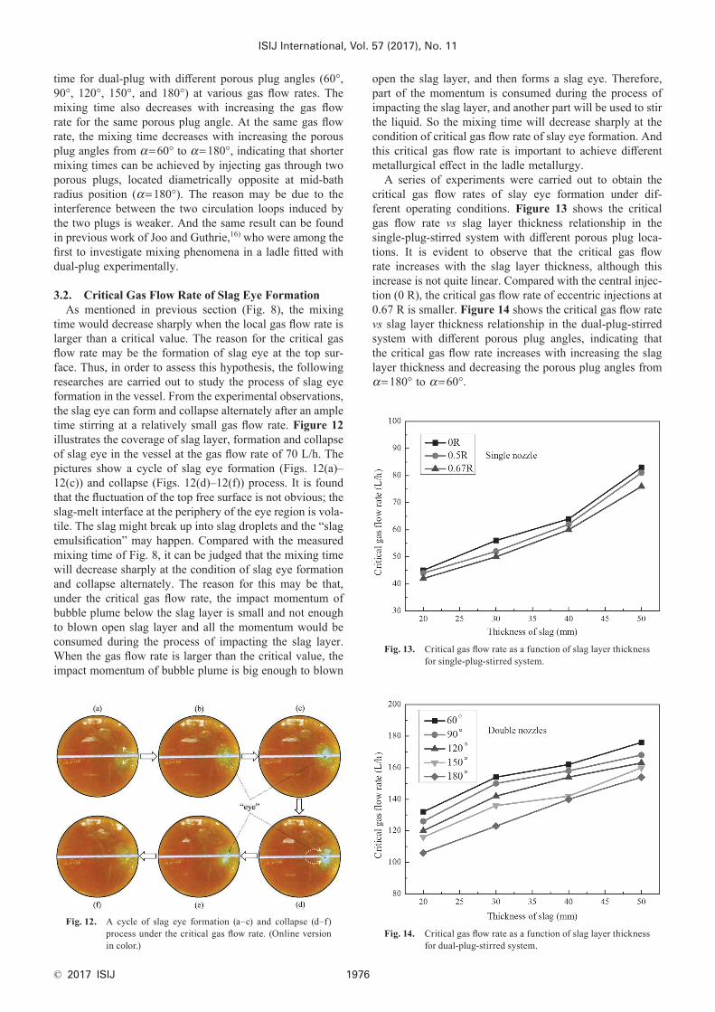
time would decrease sharply when the local gas flow rate is larger than a critical value. The reason for the critical gas flow rate may be the formation of slag eye at the top sur-face. Thus, in order to assess this hypothesis, the following researches are carried out to study the process of slag eye formation in the vessel. From the experimental observations, the slag eye can form and collapse alternately after an ample time stirring at a relatively small gas flow rate. Figure 12 illustrates the coverage of slag layer, formation and collapse of slag eye in the vessel at the gas flow rate of 70 L/h. The pictures show a cycle of slag eye formation (Figs. 12(a)–12(c)) and collapse (Figs. 12(d)–12(f)) process. It is found that the fluctuation of the top free surface is not obvious; the slag-melt interface at the periphery of the eye region is vola-tile. The slag might break up into slag droplets and the “slag emulsification” may happen. Compared with the measured mixing time of Fig. 8, it can be judged that the mixing time will decrease sharply at the condition of slag eye formation and collapse alternately. The reason for this may be that, under the critical gas flow rate, the impact momentum of bubble plume below the slag layer is small and not enough to blown open slag layer and all the momentum would be consumed during the process of impacting the slag layer. When the gas flow rate is larger than the critical value, the impact momentum of bubble plume is big enough to blown
open the slag layer, and then forms a slag eye. Therefore, part of the momentum is consumed during the process of impacting the slag layer, and another part will be used to stir the liquid. So the mixing time will decrease sharply at the condition of critical gas flow rate of slay eye formation. And this critical gas flow rate is important to achieve different metallurgical effect in the ladle metallurgy.
A series of experiments were carried out to obtain the critical gas flow rates of slay eye formation under dif-ferent operating conditions. Figure 13 shows the critical gas flow rate vs slag layer thickness relationship in the single-plug-stirred system with different porous plug loca-tions. It is evident to observe that the critical gas flow rate increases with the slag layer thickness, although this increase is not quite linear. Compared with the central injec-tion (0 R), the critical gas flow rate of eccentric injections at 0.67 R is smaller. Figure 14 shows the critical gas flow rate vs slag layer thickness relationship in the dual-plug-stirred system with different porous plug angles, indicating that the critical gas flow rate increases with increasing the slag layer thickness and decreasing the porous plug angles from α=180° to α=60°.
Fig. 12. A cycle of slag eye formation (a–c) and collapse (d–f) process under the critical gas flow rate. (Online version in color.)
Fig. 13. Critical gas flow rate as a function of slag layer thickness for single-plug-stirred system.
Fig. 14. Critical gas flow rate as a function of slag layer thickness for dual-plug-stirred system.
ISIJ International, Vol. 57 (2017), No. 11
© 2017 ISIJ1977
3.3. Analyses of Slag Eye AreaThe slag eye area fluctuated with time because of the
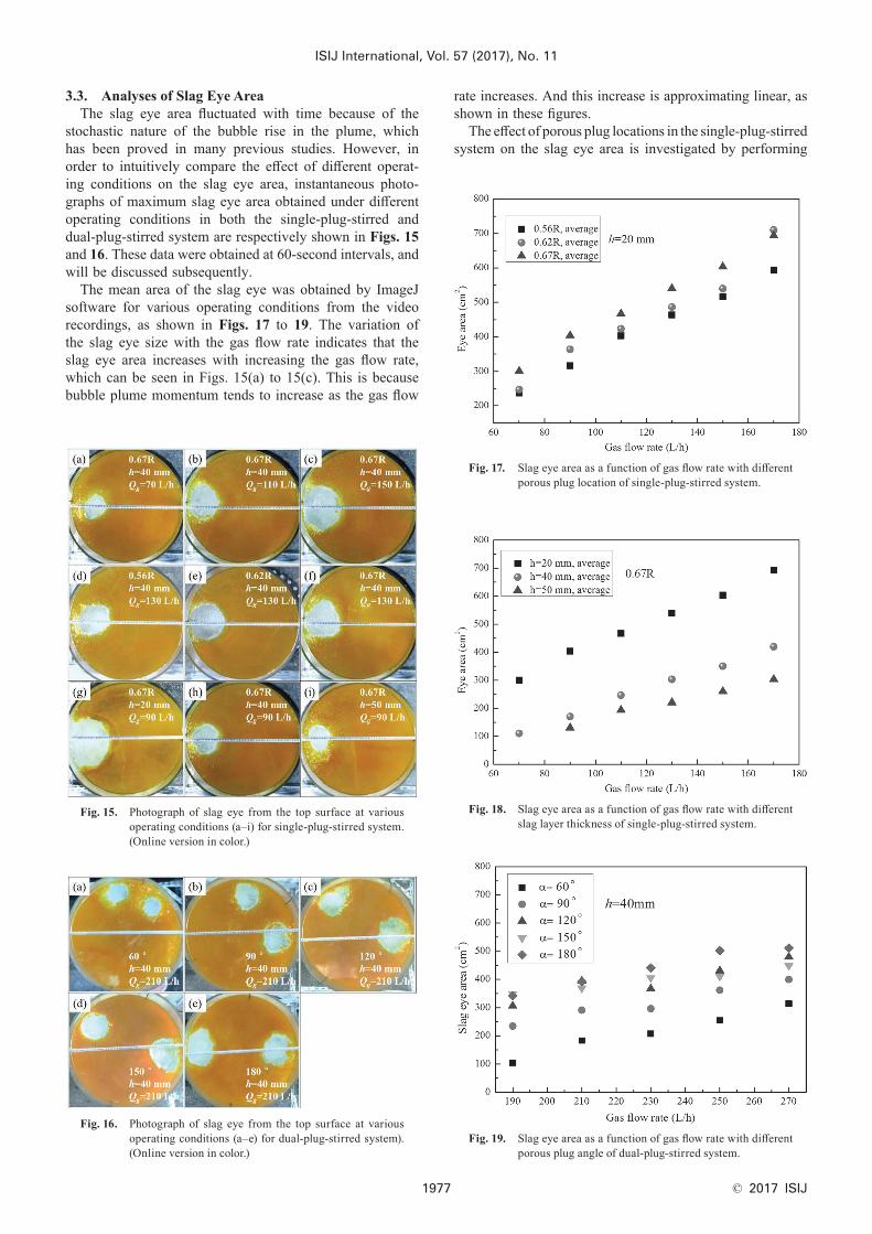
stochastic nature of the bubble rise in the plume, which has been proved in many previous studies. However, in order to intuitively compare the effect of different operat-ing conditions on the slag eye area, instantaneous photo-graphs of maximum slag eye area obtained under different operating conditions in both the single-plug-stirred and dual-plug-stirred system are respectively shown in Figs. 15 and 16. These data were obtained at 60-second intervals, and will be discussed subsequently.
The mean area of the slag eye was obtained by ImageJ software for various operating conditions from the video recordings, as shown in Figs. 17 to 19. The variation of the slag eye size with the gas flow rate indicates that the slag eye area increases with increasing the gas flow rate, which can be seen in Figs. 15(a) to 15(c). This is because bubble plume momentum tends to increase as the gas flow
rate increases. And this increase is approximating linear, as shown in these figures.
The effect of porous plug locations in the single-plug-stirred system on the slag eye area is investigated by performing
Fig. 15. Photograph of slag eye from the top surface at various operating conditions (a–i) for single-plug-stirred system. (Online version in color.)
Fig. 16. Photograph of slag eye from the top surface at various operating conditions (a–e) for dual-plug-stirred system). (Online version in color.)
Fig. 17. Slag eye area as a function of gas flow rate with different porous plug location of single-plug-stirred system.
Fig. 18. Slag eye area as a function of gas flow rate with different slag layer thickness of single-plug-stirred system.
Fig. 19. Slag eye area as a function of gas flow rate with different porous plug angle of dual-plug-stirred system.
ISIJ International, Vol. 57 (2017), No. 11
© 2017 ISIJ 1978
different porous plug locations of 0.56 R, 0.62 R, and 0.67 R. Figures 15(d) to 15(f) show the slag eye distribution at the top surface with different porous plug locations. It can be seen that the porous plug locations has little influence on the slag eye area. The slag eye area increases only by a small amount when the porous plug location moves from the center to the wall of the vessel, as shown in Fig. 17. This is likely because the liquid momentum tends to concentrate more near the wall when the porous plug location is closer to the wall.
The effect of slag layer thickness in the single-plug-stirred system on the slag eye area is investigated with increasing the slag layer thickness from 20 to 40 and 50 mm for the same gas injection location (0.67 R), as shown in Figs. 15(g) to 15(i). It can be seen that the slag layer thickness has large influence on the slag eye area. The slag eye area would increase quickly with the slag layer thickness decreases. Figure 18 shows the slag eye area variation with slag layer thickness at various gas flow rates and different gas injection locations. It is interesting that the eye area increases with decreasing the slag layer thickness, although this increase is not quite linear. These results may be related to the observa-tion that the broadening of the bubble plume is not linearly dependent on the slag layer thickness.
Figures 16(a) to 16(e) show the effect of porous plug angles in the dual-plug-stirred system on the slag eye area with increasing the porous plug angles from α=60° to α=180° for the same slag layer thickness of 40 mm. It can be seen that the porous plug angles has large influence on the slag eye area. The slag eye area increases by a big amount when the porous plug angles increases from α=60° to α=180°, as shown in Fig. 19. This is likely because the mutual interference between two porous plugs is weaker with larger porous plug angles (smaller distance). More bubble plume momentum can be used to impact the slag layer. Then, a larger slag eye will be formed.
3.4. Comparisons with Previous Correlations for Slag Eye Area
Extensive studies of the dimensionless eye area in the gas-stirred ladle have been proposed based on the physical modeling. However, relatively little work has been reported on the dimensionless eye area in ladle metallurgy with eccentric and multi- plugs gas bubbling. Two previously published correlations for eye size have been evaluated using the current experimental data, and some new numeri-cal constants which depend on the characteristics of the gas-liquid system and vessel dimensions were obtained. Details can be seen below.
Yonezawa and Schwerdtfeger9) have carried out cold model experiments on studying the sizes of slag eyes using mercury and silicon oil as metal and slag, respectively. The time-averaged slag eye area has been represented in the form of non-dimensional correlations:
A
hHf
Q
ghe =
2
5 .............................. (6)
where Ae is the area of the eye. h is the slag layer thickness and H is the height of the liquid steel. Q is the gas flow rate.
Using the present experimental data, through the poly-nomial fitting method, we have proposed a correlation that
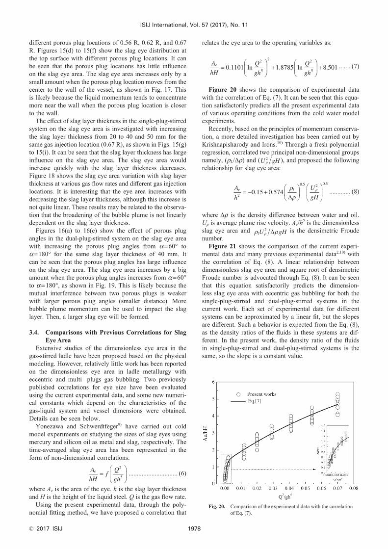
relates the eye area to the operating variables as:
A
hH
Q
gh
Q
ghe =
+
+0 1101 1 8785 8 501
2
5
2 2
5. ln . ln . ....... (7)
Figure 20 shows the comparison of experimental data with the correlation of Eq. (7). It can be seen that this equa-tion satisfactorily predicts all the present experimental data of various operating conditions from the cold water model experiments.
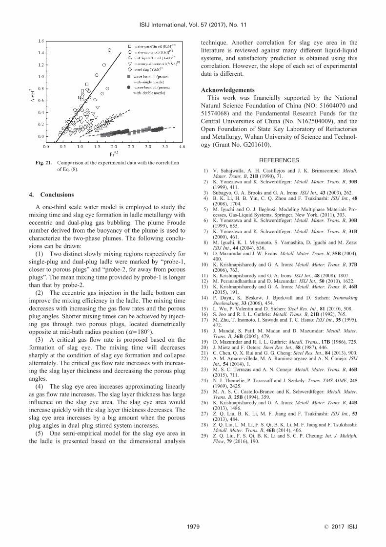
Recently, based on the principles of momentum conserva-tion, a more detailed investigation has been carried out by Krishnapisharody and Irons.10) Through a fresh polynomial regression, correlated two principal non-dimensional groups namely, (ρL/Δρ) and (U gHp
2 ), and proposed the following relationship for slag eye area:
A
h
U
gHe l p
2
0 5 2 0 5
0 15 0 574= − +
. .
. .ρρ∆
............. (8)
where Δρ is the density difference between water and oil. Up is average plume rise velocity. Ae/h2 is the dimensionless slag eye area and ρ ρl pU gH2 ∆ is the densimetric Froude number.
Figure 21 shows the comparison of the current experi-mental data and many previous experimental data2,10) with the correlation of Eq. (8). A linear relationship between dimensionless slag eye area and square root of densimetric Froude number is advocated through Eq. (8). It can be seen that this equation satisfactorily predicts the dimension-less slag eye area with eccentric gas bubbling for both the single-plug-stirred and dual-plug-stirred systems in the current work. Each set of experimental data for different systems can be approximated by a linear fit, but the slopes are different. Such a behavior is expected from the Eq. (8), as the density ratios of the fluids in these systems are dif-ferent. In the present work, the density ratio of the fluids in single-plug-stirred and dual-plug-stirred systems is the same, so the slope is a constant value.
Fig. 20. Comparison of the experimental data with the correlation of Eq. (7).
ISIJ International, Vol. 57 (2017), No. 11
© 2017 ISIJ1979
4. Conclusions
A one-third scale water model is employed to study the mixing time and slag eye formation in ladle metallurgy with eccentric and dual-plug gas bubbling. The plume Froude number derived from the buoyancy of the plume is used to characterize the two-phase plumes. The following conclu-sions can be drawn:
(1) Two distinct slowly mixing regions respectively for single-plug and dual-plug ladle were marked by “probe-1, closer to porous plugs” and “probe-2, far away from porous plugs”. The mean mixing time provided by probe-1 is longer than that by probe-2.
(2) The eccentric gas injection in the ladle bottom can improve the mixing efficiency in the ladle. The mixing time decreases with increasing the gas flow rates and the porous plug angles. Shorter mixing times can be achieved by inject-ing gas through two porous plugs, located diametrically opposite at mid-bath radius position (α=180°).
(3) A critical gas flow rate is proposed based on the formation of slag eye. The mixing time will decreases sharply at the condition of slag eye formation and collapse alternately. The critical gas flow rate increases with increas-ing the slag layer thickness and decreasing the porous plug angles.
(4) The slag eye area increases approximating linearly as gas flow rate increases. The slag layer thickness has large influence on the slag eye area. The slag eye area would increase quickly with the slag layer thickness decreases. The slag eye area increases by a big amount when the porous plug angles in dual-plug-stirred system increases.
(5) One semi-empirical model for the slag eye area in the ladle is presented based on the dimensional analysis
technique. Another correlation for slag eye area in the literature is reviewed against many different liquid-liquid systems, and satisfactory prediction is obtained using this correlation. However, the slope of each set of experimental data is different.
AcknowledgementsThis work was financially supported by the National
Natural Science Foundation of China (NO: 51604070 and 51574068) and the Fundamental Research Funds for the Central Universities of China (No. N162504009), and the Open Foundation of State Key Laboratory of Refractories and Metallurgy, Wuhan University of Science and Technol-ogy (Grant No. G201610).
REFERENCES
1) V. Sahajwalla, A. H. Castillejos and J. K. Brimacombe: Metall. Mater. Trans. B, 21B (1990), 71.
2) K. Yonezawa and K. Schwerdtfeger: Metall. Mater. Trans. B, 30B (1999), 411.
3) Subagyo, G. A. Brooks and G. A. Irons: ISIJ Int., 43 (2003), 262.4) B. K. Li, H. B. Yin, C. Q. Zhou and F. Tsukihashi: ISIJ Int., 48
(2008), 1704.5) M. Iguchi and O. J. Ilegbusi: Modeling Multiphase Materials Pro-
cesses, Gas-Liquid Systems, Springer, New York, (2011), 303.6) K. Yonezawa and K. Schwerdtfeger: Metall. Mater. Trans. B, 30B
(1999), 655.7) K. Yonezawa and K. Schwerdtfeger: Metall. Mater. Trans. B, 31B
(2000), 461.8) M. Iguchi, K. I. Miyamoto, S. Yamashita, D. Iguchi and M. Zeze:
ISIJ Int., 44 (2004), 636.9) D. Mazumdar and J. W. Evans: Metall. Mater. Trans. B, 35B (2004),
400.10) K. Krishnapisharody and G. A. Irons: Metall. Mater. Trans. B, 37B
(2006), 763.11) K. Krishnapisharody and G. A. Irons: ISIJ Int., 48 (2008), 1807.12) M. Peranandhanthan and D. Mazumdar: ISIJ Int., 50 (2010), 1622.13) K. Krishnapisharody and G. A. Irons: Metall. Mater. Trans. B, 46B
(2015), 191.14) P. Dayal, K. Beskow, J. Bjorkvall and D. Sichen: Ironmaking
Steelmaking, 33 (2006), 454.15) L. Wu, P. Valentin and D. Sichen: Steel Res. Int., 81 (2010), 508.16) S. Joo and R. I. L. Guthrie: Metall. Trans. B, 21B (1992), 765.17) M. Zhu, T. Inomoto, I. Sawada and T. C. Hsiao: ISIJ Int., 35 (1995),
472.18) J. Mandal, S. Patil, M. Madan and D. Mazumdar: Metall. Mater.
Trans. B, 36B (2005), 479.19) D. Mazumdar and R. I. L. Guthrie: Metall. Trans., 17B (1986), 725.20) J. Mietz and F. Oeters: Steel Res. Int., 58 (1987), 446.21) C. Chen, Q. X. Rui and G. G. Cheng: Steel Res. Int., 84 (2013), 900.22) A. M. Amaro-villeda, M. A. Ramirez-argaez and A. N. Conejo: ISIJ
Int., 54 (2014), 1.23) M. S. C. Terrazas and A. N. Conejo: Metall. Mater. Trans. B, 46B
(2015), 711.24) N. J. Themelie, P. Tarassoff and J. Szekely: Trans. TMS-AIME, 245
(1969), 2425.25) M. A. S. C. Castello-Branco and K. Schwerdtfeger: Metall. Mater.
Trans. B, 25B (1994), 359.26) K. Krishnapisharody and G. A. Irons: Metall. Mater. Trans. B, 44B
(2013), 1486.27) Z. Q. Liu, B. K. Li, M. F. Jiang and F. Tsukihashi: ISIJ Int., 53
(2013), 484.28) Z. Q. Liu, L. M. Li, F. S. Qi, B. K. Li, M. F. Jiang and F. Tsukihashi:
Metall. Mater. Trans. B, 46B (2014), 406.29) Z. Q. Liu, F. S. Qi, B. K. Li and S. C. P. Cheung: Int. J. Multiph.
Flow, 79 (2016), 190.
Fig. 21. Comparison of the experimental data with the correlation of Eq. (8).