Embed Size (px)
Citation preview

Modeling of and experiments on dust particle levitation in the sheath of a radiofrequency plasma reactorHeru Setyawan, Manabu Shimada, Yutaka Hayashi, Kikuo Okuyama, and Sugeng Winardi
Citation: Journal of Applied Physics 97, 043306 (2005); doi: 10.1063/1.1852696 View online: http://dx.doi.org/10.1063/1.1852696 View Table of Contents: http://scitation.aip.org/content/aip/journal/jap/97/4?ver=pdfcov Published by the AIP Publishing Articles you may be interested in Investigation of the sheath formation in a dusty plasma containing energetic electrons and nano-size dust grains Phys. Plasmas 19, 103505 (2012); 10.1063/1.4764074 Numerical study of an electrostatic plasma sheath containing two species of charged dust particles J. Appl. Phys. 112, 073301 (2012); 10.1063/1.4755798 Determination of the levitation limits of dust particles within the sheath in complex plasma experiments Phys. Plasmas 19, 013707 (2012); 10.1063/1.3677360 Dust charge and ion drag forces in a high-voltage, capacitive radio frequency sheath Phys. Plasmas 16, 113707 (2009); 10.1063/1.3263682 Dust particle dynamics in magnetized plasma sheath Phys. Plasmas 12, 073505 (2005); 10.1063/1.1948667
[This article is copyrighted as indicated in the article. Reuse of AIP content is subject to the terms at: http://scitation.aip.org/termsconditions. Downloaded to ] IP:
131.156.59.191 On: Tue, 02 Sep 2014 04:36:00

Modeling of and experiments on dust particle levitation in the sheathof a radio frequency plasma reactor
Heru SetyawanDepartment of Chemical Engineering, Faculty of Industrial Technology, Sepuluh Nopember Instituteof Technology (ITS), Kampus ITS Sukolilo, Surabaya 60111, Indonesia
Manabu Shimada,a! Yutaka Hayashi, and Kikuo OkuyamaDepartment of Chemical Engineering, Graduate School of Engineering, Hiroshima University, 1-4-1Kagamiyama, Higashi-Hiroshima 739-8527, Japan
Sugeng WinardiDepartment of Chemical Engineering, Faculty of Industrial Technology, Sepuluh Nopember Instituteof Technology (ITS), Kampus ITS Sukolilo, Surabaya 60111, Indonesia
sReceived 21 June 2004; accepted 1 December 2004; published online 26 January 2005d
The equilibrium and trapping of dust particles in a plasma sheath are investigated, bothexperimentally and theoretically. A self-consistent sheath model including input power as one of themodel parameters is proposed, to predict the equilibrium position of particle trap. The electrontemperature and density are estimated from the observed current and powersI-Pd characteristicsusing the sheath model developed. Direct comparisons are made between the measured equilibriumposition and the predicted equilibrium position. The equilibrium position moves closer to theelectrode with increasing rf power and particle size. The position is apparently related to the sheaththickness, which decreases with increasing rf power. The model can correctly predict theexperimentally observed trend in the equilibrium position of particle trap. It is found that the particlecharge becomes positive when the particle gets closer to the electrode, due to the dominant influenceof ion currents to the particle surface. ©2005 American Institute of Physics.fDOI: 10.1063/1.1852696g
I. INTRODUCTION
Dust particles generated in the plasma processes forsemiconductor manufacturing have been recognized to havedeleterious effects on the wafer being processed. Experimen-tal observations have shown that dust particles are trapped inthe sheath or presheath region near boundaries under the bal-ance of various forces that may include gravitational, elec-trostatic, ion drag, neutral drag, and thermophoretic forces.1,2
The presence of ion drag force is also believed as the dy-namical trigger for a void formation, a local dust-free regionwith sharp boundaries.3,4 The size, concentration, and struc-ture of the particle clouds in the trap depend considerably onthe plasma operating conditions.5 In addition, the cloudstructure also influences wafer contamination.6,7 Recently,several applications that take advantage of dusty plasmashave emerged, including production of powders with con-trolled properties, surface modification of dust particles, andinclusion of nanometer-sized particles into thin film for wearresistance.8 Since dust particles in plasma are confined nearthe sheath edge, understanding particle trap in the sheathregion is important for determining the optimal conditionsfor technological treatment of dust particles.
Several studies that investigate theoretically the levita-tion of dust particles in the plasma sheath have been carriedout.9–14 In general, there are two approaches to modeling thesheath containing dust particles:sid the dust particles do not
influence the sheath field, andsii d the dust particles influencethe plasma properties. In the above studies, however, thedistance of particle trap from the electrode wall was not animportant issue. The trap position is usually determined interms of the Debye length with respect to the sheath edge.Only Vladimirov and Cramer12 have considered the distancefrom the electrode wall. However, in their study, the elec-trode potential was taken to be an arbitrarily constant valuethat did not describe the actual value of the electrode poten-tial. Consequently, the calculated trap position also did notdescribe the actual distance from the electrode. Indeed, thedistance from the electrode is much more important than thatfrom the sheath edge. This is because detailed knowledge ofthe forces acting on particles and particle motion, which arestrongly affected by their interaction with the electric field infront of the electrodes, is required to determine the responsesof particles to varying external plasma parameters in the ap-plication of surface-processing reactors. The existing modelsalso do not include the plasma operating parameters, e.g.,input power, in the model parameters. In addition, there is noreport in which the dusty sheath models are compared di-rectly to experimental measurements.
In plasma etching and deposition processes, the energyof ions incident onto the substrate strongly influences thesurface reactions and the film deposition and etchingrates.15,16 The ions gain the energy from the strong electricfield that exists near the surface as they travel from the bulkplasma across the sheath towards the substrate. The energyof ions impinging on the surface ranges from tens to hun-
adAuthor to whom correspondence should be addressed; electronic mail:[email protected]
JOURNAL OF APPLIED PHYSICS97, 043306s2005d
0021-8979/2005/97~4!/043306/6/$22.50 © 2005 American Institute of Physics97, 043306-1
[This article is copyrighted as indicated in the article. Reuse of AIP content is subject to the terms at: http://scitation.aip.org/termsconditions. Downloaded to ] IP:
131.156.59.191 On: Tue, 02 Sep 2014 04:36:00

dreds of electron volts. In the deposition ofa-Si:H, ions withan energy larger than 20 eV will be implanted in thehydrogen-rich subsurface of the growing film, and may causestructural changes.16 The spatial distribution of the electricfields within the sheath together with the sheath thicknessdetermine the energy of the ions impinging on the surface.Therefore, knowledge of the spatial distribution of thesefields is important for enabling the best design of manufac-turing processes. This needs a self-consistent sheath modelthat can accurately predict both the sheath fields and thesheath thickness.
In this article, measurements of the equilibrium positionof particle trap in a rf capacitive plasma are presented. Aself-consistent model of the sheath, capable of predicting thecharacteristic curve of discharge current and powersI-Pcharacteristicsd, is developed. The electron density and tem-perature are determined by fitting the calculatedI-P charac-teristics to the measuredI-P characteristics. Then, the equi-librium position of particle trap is calculated based on thecalculated sheath field using the best-fit values of electrondensity and temperature. The predicted equilibrium positionof particle trap is then compared with the experimental data.
II. EXPERIMENTAL WORK
The experiments were carried out in a 13.56 MHz ra-diofrequencysrfd capacitively coupled plasma reactor filledwith nitrogen gas. The reactor is a conventional parallel-platetype that consists of two cylindrical plates 200 mm in diam-eter separated by 35 mm.5–7,17The upper plate, which is in ashowerhead configuration, is coupled to the rf power and thelower plate is grounded. The reactor was seeded with mono-disperse silica particles injected from the outside through theshowerhead together with gas flow. Particle clouds in thereactor were observed using a laser light scattering techniquecombined with video imaging. The particle injection and vi-sualization systems have been described in detail else-where.5,6
III. SHEATH MODEL
We consider the sheath near an rf electrode as a colli-sional sheath without ionization source due to the low effi-ciency of electron-impact process to produce nitrogen ions.18
Since the gradients of ion and electron densities and the po-tential in the direction normal to the electrode are muchhigher than those in other directions, one-dimensional analy-sis is considered sufficient. The sheath configuration is illus-trated in Fig. 1, where the sheath edge is located at the originof the reference framex=0, and the end of the simulationvolume is at the edge of the electrode,x=L. It is assumedthat the plasma consists of electrons and singly charged ionswith a uniform background gas and that the dust particleshave no influence on the sheath field. The spatial distributionof the ion density and velocity and the electric potential aredescribed by the time-averaged equations of ion continuityand momentum balance and Poisson’s equation. The ion con-tinuity is given by
dsuiniddx
= 0, s1d
the ion momentum balance is
uidui
dx= −
e
mi
dV
dx−
Fcoll
mi, s2d
and the Poisson’s equation is
d2V
dx2 = −e
«0sni − ned. s3d
In Eqs. s1d–s3d, ni and ne are the number densities of ionsand electrons,ui is the ion velocity, andV is the potential inthe sheath.e, mi, and «0 are the unit charge, the ion mass,and the permittivity in the free space, respectively.Fcoll is themomentum transfer rate between ions and neutrals, and isgiven by12
Fcoll = nEfsddui . s4d
Here,d= uuiu /Î2uTis1+Tn/Tid1/2, nE is the average charge ex-change collision frequency and is given by
nE =8
3Î 2
pqEnnuTiS1 +
Tn
TiD1/2
, s5d
where qE is the characteristic charge exchange momentumtransfer cross section,nn the density of the neutral gas,uTi
the ion thermal velocity, andTi andTn are the ion and neutraltemperature, respectively. The functionfsdd is given by
fsdd =3
8d3FSd3 +d
2Dexps− d2d
+Îp
dSd5 + d3 −
d
4DerfsddG . s6d
The energy distribution of the electrons in the plasma isassumed to obey a Maxwell–Boltzmann distribution charac-terized by an electron temperatureTe. Therefore, the electrondensity as a function of position in the sheath can be givenby
ne = n0 expS eV
kBTeD , s7d
wheren0 is the electron density at the plasma-sheath bound-ary andkB is the Boltzmann’s constant.
FIG. 1. Schematic diagram of the rf sheath model. The equilibrium positionof particle trapdeq is defined as the position where the net force acting onthe particle is zero. The sheath thicknessds is taken to be the distancebetween the electrode and the point at which the electron density has fallento half its value at the sheath edge.
043306-2 Setyawan et al. J. Appl. Phys. 97, 043306 ~2005!
[This article is copyrighted as indicated in the article. Reuse of AIP content is subject to the terms at: http://scitation.aip.org/termsconditions. Downloaded to ] IP:
131.156.59.191 On: Tue, 02 Sep 2014 04:36:00

Appropriate boundary conditions at the plasma–sheathinterface should be chosen to completely define the problem.In this model, the sheath boundary conditions are based onthe Bohm criterion, which is also valid for rf sheaths.19 Thus,we assume that at the sheath–presheath boundaryx=0 theion density should be equal to the electron density, i.e., thequasineutral condition
nis0d = nes0d = n0. s8d
Moreover, we also assume that ions enter the sheath with avelocity equal to the Bohm velocityuB
uis0d = uB =ÎkBTe
mi. s9d
Since the potential reference can be taken arbitrarily, we setthe potential at the sheath-presheath edge to be zero
Vs0d = 0. s10d
We took a small, nonzero value for the electric field as theboundary condition at the sheath–presheath edge. This is agood approximation as long as it is small, and thus enablesus to decouple the sheath model from the plasma model.20 Atthe electrodesx=Ld, the ion density and velocity can be ex-trapolated andV is set equal to the electrode potentialVe,i.e.,
VsLd = Ve. s11d
Among the boundary conditions, unfortunately,Ve is un-known. Here, we used the corrected Child’s law sheath thick-ness of a dc sheath to estimate the potential at the electrode.The electron density in the sheath for an rf sheath cannot beignored, an rf sheath is larger than a dc sheath by a factor ofÎ50/27.21 Then, the rf sheath thicknessds is given by
ds =2
3Î50Î2
27lDS eVs
kBTeD3/4
, s12d
wherelD is the electron Debye length andVs is the potentialdrop across the sheath. The sheath thickness is taken to bethe distance between the electrode and the point at which theelectron density has fallen to half its value at the sheathedge.20 Equationss1d–s12d give a set of closed nonlinearequations that determine the time-averaged field of the rfsheath. The above equations with the boundary conditionswill be solved numerically using an iterative process in aself-consistent manner.
IV. CHARGE AND FORCES ACTING ON A PARTICLE
The charge of a particle in the sheath is determined fromthe condition of zero net current onto the particle surface
I = Ie + I i = 0, s13d
whereIe and I i are the electron and ion currents to the par-ticle, respectively. The electron current is given by14
Ie = − epdd
2
4S8kBTe
pmeD1/2
n0 expS eV
kBTeDexpS eVd
kBTeD
foreVd
kBTeø 0, s14d
Ie = − epdd
2
4S8kBTe
pmeD1/2
n0 expS eV
kBTeDS1 +
eVd
kBTeD
foreVd
kBTe. 0, s15d
and the ion current is given by
I i = pdd
2
4eniuiS1 −
2eVd
miui2D , s16d
wheredd is the particle diameter andVd is the floating po-tential on the particle surface. The mean ion velocity,ui isgiven by
ui =Îui2 +
8kBTi
pmi. s17d
Then, the particle charge can be determined from
qd = 2p«0ddVd. s18d
For particles levitating in the sheath field, the forces act-ing on the particles should be balanced, i.e., the sum of theforces must be zero, that is
o F = 0. s19d
In this model, we include gravity, electrostatic, and ion dragforces. The gravity force is given by
Fg =p
6dd
3rdg, s20d
whererd is the particle density andg is the gravity accelera-tion.
The electrostatic force is given by
Fe = − qddV
dx. s21d
In this case, it is assumed that the particle inertia is large sothat it responds only to the time-averaged electrical force.
The ion drag force consists of two components, the col-lection and the orbit forces.22 The collection force representsthe momentum transfer from all ions that are collected by aparticle and can be expressed as
Fi,c = niuimiuibc2. s22d
The orbit force represents the Coulomb drag due to momen-tum transfer from ions not sticking to the particle surface.This force is given by
Fi,o = 2pniuimiuibo2G, s23d
whereG is the Coulomb logarithmic and is given by
043306-3 Setyawan et al. J. Appl. Phys. 97, 043306 ~2005!
[This article is copyrighted as indicated in the article. Reuse of AIP content is subject to the terms at: http://scitation.aip.org/termsconditions. Downloaded to ] IP:
131.156.59.191 On: Tue, 02 Sep 2014 04:36:00
G = lnSlD2 + bo
2
bc2 + bo
2 D . s24d
bc and bo are the impact parameters and are given, respec-tively, by
bc =dd
2S1 −
2eVd
miui2D1/2
, s25d
bo =eddVd
2miui2 . s26d
V. RESULTS AND DISCUSSION
A. Particle trap observations
The following data are for the case of plasma derivedfrom nitrogen gas at a pressure of 3 Torr and ambient tem-perature. Figure 2sad shows video images of particles trappedbelow the showerhead for 0.6mm monodisperse silica par-ticles at two different rf powers. The gas flow was stoppedafter particle injection. Measurements of the equilibrium po-sition of particle trap were carried out at this condition. Theparticles are trapped in localized regions between the show-erhead holes. No particles are observed just below the holes.This may be caused by the perturbation of the electric fielduniformity due to the discontinuity of the electrode surface,and has been discussed in detail elsewhere.5 The method todetermine the equilibrium position of particle trap is depictedin Fig. 2sbd. The equilibrium position is taken as the averagedistance of the lower and the upper boundaries of the particleclouds, measured from the powered electrode surface.
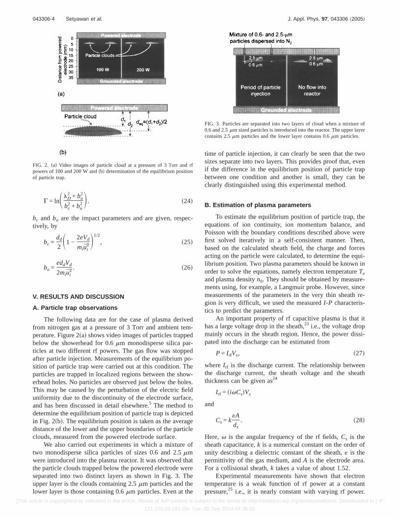
We also carried out experiments in which a mixture oftwo monodisperse silica particles of sizes 0.6 and 2.5mmwere introduced into the plasma reactor. It was observed thatthe particle clouds trapped below the powered electrode wereseparated into two distinct layers as shown in Fig. 3. Theupper layer is the clouds containing 2.5mm particles and thelower layer is those containing 0.6mm particles. Even at the
time of particle injection, it can clearly be seen that the twosizes separate into two layers. This provides proof that, evenif the difference in the equilibrium position of particle trapbetween one condition and another is small, they can beclearly distinguished using this experimental method.
B. Estimation of plasma parameters
To estimate the equilibrium position of particle trap, theequations of ion continuity, ion momentum balance, andPoisson with the boundary conditions described above werefirst solved iteratively in a self-consistent manner. Then,based on the calculated sheath field, the charge and forcesacting on the particle were calculated, to determine the equi-librium position. Two plasma parameters should be known inorder to solve the equations, namely electron temperatureTe
and plasma densityn0. They should be obtained by measure-ments using, for example, a Langmuir probe. However, sincemeasurements of the parameters in the very thin sheath re-gion is very difficult, we used the measuredI-P characteris-tics to predict the parameters.
An important property of rf capacitive plasma is that ithas a large voltage drop in the sheath,23 i.e., the voltage dropmainly occurs in the sheath region. Hence, the power dissi-pated into the discharge can be estimated from
P = I rfVs, s27d
where I rf is the discharge current. The relationship betweenthe discharge current, the sheath voltage and the sheaththickness can be given as24
I rf = sivCsdVs
and
Cs = k«A
ds. s28d
Here, v is the angular frequency of the rf fields,Cs is thesheath capacitance,k is a numerical constant on the order ofunity describing a dielectric constant of the sheath,« is thepermittivity of the gas medium, andA is the electrode area.For a collisional sheath,k takes a value of about 1.52.
Experimental measurements have shown that electrontemperature is a weak function of rf power at a constantpressure,25 i.e., it is nearly constant with varying rf power.
FIG. 2. sad Video images of particle cloud at a pressure of 3 Torr and rfpowers of 100 and 200 W andsbd determination of the equilibrium positionof particle trap.
FIG. 3. Particles are separated into two layers of cloud when a mixture of0.6 and 2.5mm sized particles is introduced into the reactor. The upper layercontains 2.5mm particles and the lower layer contains 0.6mm particles.
043306-4 Setyawan et al. J. Appl. Phys. 97, 043306 ~2005!
[This article is copyrighted as indicated in the article. Reuse of AIP content is subject to the terms at: http://scitation.aip.org/termsconditions. Downloaded to ] IP:
131.156.59.191 On: Tue, 02 Sep 2014 04:36:00

This is not the case for electron density, which increases withincreasing rf power. Hence, we assume that the only param-eter that changes with a changing rf power is electron den-sity, whereas the electron temperature is kept constant. Theelectron temperature is determined in such a way that theI-P characteristics calculated with varying electron densitiesbest fit the measuredI-P characteristics. Figure 4 shows themeasuredI-P characteristics and the estimated curves usingthree different electron temperatures, that is, 1.0, 1.9, and3.0 eV. The electron temperature of 1.9 eV was found togive the best fit to the measurements. The electron density atTe=1.9 eV takes the values of about 1.731015 to 1.0631017 m−3 for rf powers ranging from 50 to 400 W, respec-tively, as shown in Fig. 5.
C. Equilibrium position of particle trap
The results presented in the following section were cal-culated usingTe=1.9 eV, which is the best-fit value for elec-tron temperature in our system, and the ion temperatureTi isassumed the same as that of the background gas. Figure 6shows the spatial distribution of the particle charge in thesheath for particle sizes of 0.6 and 2.5mm at a plasma den-sity of 6.931015 m−3 scorresponding to an rf power of about100 Wd. The particle charge becomes positive near the elec-trode. In this region, the sheath potential is strong enoughthat the ion current dominates. This means that the particlecannot levitate in this region and must deposit onto the elec-trode. This fact agrees with experimental observations show-ing that particles present in the sheath region close to theelectrode surface carry positive charge.26
Figure 7 shows the equilibrium position of particle trapas a function of rf power. The symbols indicate the measuredequilibrium position and the lines indicate the calculated one.The equilibrium position moves closer to the electrode withincreasing rf power. The calculation follows the same trendas the experimental observations, for particle sizes of both0.6 and 2.5mm. It seems that the position is related to thesheath thickness. As shown in Fig. 5, the sheath thicknessdecreases with increasing rf power. The fact that the sheaththickness decreases with increasing rf power agrees with ex-perimental observations.27 The plasma density increases withincreasing rf power, which gives a shorter Debye length, thusreducing the sheath thickness.
The equilibrium position of the particle trap shifts closerto the electrode with increasing particle size at a constant rfpower. This shows that the effect of gravity can be neglectedat this size range, as the larger size is located at the upperposition. The calculation follows the same trend as the ex-perimental observations. As shown in Fig. 8, when the par-ticle size is increased, the equilibrium position decreasesvery rapidly for small particles, then becomes nearly con-stant for large particles. It should be noted that the largerparticles carry more charges than the smaller ones. More-over, the electrostatic force is directly proportional to theparticle charge, whereas the ion drag force is proportional tothe square of the particle charge. Therefore, when the particlesize increases, the ion drag force increases much faster thanthe electrostatic force, such that the larger particles aredragged closer to the electrode. However, the intensity of theelectric field increases when the particle gets closer to theelectrode, which makes the electrostatic force increase. Con-sequently, the equilibrium position is nearly independent ofparticle size for large particles.
FIG. 4. Comparison of the measured and calculated characteristics ofI-P.The lines show the calculated characteristics for three different values ofelectron temperature, that is, 1.0, 1.9, and 3.0 eV. The electron temperatureof 1.9 eV provides the best fit to the measuredI-P characteristics.
FIG. 5. Dependence of sheath thickness and plasma density on rf power.
FIG. 6. Spatial distribution of particle charge in the sheath for particles 0.6and 2.5mm in size.
FIG. 7. Equilibrium position of particle trap as a function of rf power.
043306-5 Setyawan et al. J. Appl. Phys. 97, 043306 ~2005!
[This article is copyrighted as indicated in the article. Reuse of AIP content is subject to the terms at: http://scitation.aip.org/termsconditions. Downloaded to ] IP:
131.156.59.191 On: Tue, 02 Sep 2014 04:36:00

In our calculations, we assumed that all the input powerforwarded by the rf generator is delivered to the plasmathrough the sheath region, i.e., there is no power loss. Inreality, there must be power loss in the matching network,and the voltage across the bulk region should be considered.However, since the voltage across the bulk region is muchsmaller than that in sheath region,24 the power loss can beconsidered to primarily occur in the matching network. Thus,if we know the amount of power that is actually delivered tothe plasma, the electron temperature and density can be es-timated more accurately. Hence, this method may also beused to measure the electron temperature and density in ca-pacitively coupled rf plasmas, and as a tool to monitor theperformance of the plasma reactor during processes, bymonitoring theI-P characteristics.
VI. CONCLUSIONS
It has been demonstrated that the developed self-consistent sheath model including input power as one of themodel parameters can predict the equilibrium position of par-ticle trap observed experimentally. The model can also beused to predict the electron temperature and density using themeasuredI-P characteristics. If the actual power delivered tothe plasma can be measured accurately, it will be possible touse this method to monitor the electron temperature and den-sity in capacitively coupled rf plasmas during processes. Theequilibrium position moves closer to the electrode with in-creasing rf power and particle size. The position is appar-ently related to the sheath thickness, which decreases withincreasing rf power. It was found that the particle charge
becomes positive when the particle gets closer to the elec-trode, due to the dominant influence of ion currents to theparticle surface.
ACKNOWLEDGMENTS
The authors thank Y. Imajo for help in the experimentalwork. This work was partly supported by Innovation PlazaHiroshima of JSTsJapan Science and Technology Agencydand a Grant-in-Aid from the Ministry of Education, Sports,Culture, Science, and Technology of Japan.
1G. S. Selwyn, J. E. Heidenreich, and K. L. Haller, J. Vac. Sci. Technol. A9, 2817s1991d.
2J. E. Daugherty and D. B. Graves, J. Appl. Phys.78, 2279s1995d.3D. Samsonov and J. Goree, Phys. Rev. E59, 1047s1999d.4R. P. Dahiya, G. V. Paeva, W. W. Stoffels, E. Stoffels, G. M. W. Kroesen,K. Avinash, and A. Bhattacharjee, Phys. Rev. Lett.89, 125001s2002d.
5H. Setyawan, M. Shimada, and K. Okuyama, J. Appl. Phys.92, 5525s2002d.
6H. Setyawan, M. Shimada, Y. Imajo, Y. Hayashi, and K. Okuyama, J.Aerosol Sci. 34, 923 s2003d.
7H. Setyawan, M. Shimada, Y. Hayashi, K. Okuyama, and S. Yokoyama,Aerosol Sci. Technol.38, 120 s2004d.
8H. Kersten, H. Deutsch, E. Stoffels, W. W. Stoffels, G. M. W. Kroesen,and R. Hippler, Contrib. Plasma Phys.41, 598 s2001d.
9A. Brattli and O. Havnes, J. Vac. Sci. Technol. A14, 644 s1996d.10J. X. Ma, J. Liu, and M. Y. Yu, Phys. Rev. E55, 4627s1997d.11J. Liu, D. Wang, T. C. Ma, Y. Gong, Q. Sun, J. X. Ma, and C. X. Yu, Phys.
Plasmas6, 1405s1999d.12S. V. Vladimirov and N. F. Cramer, Phys. Rev. E62, 2754s2000d.13D. J. Kim and K. S. Kim, Aerosol Sci. Technol.32, 293 s2000d.14D. Wang and X. Wang, J. Appl. Phys.89, 3602s2001d.15S. Takagi, K. Iyanagi, S. Onoue, T. Shinmura, and M. Fujino, Jpn. J. Appl.
Phys., Part 141, 3947s2002d.16W. G. J. H. M. van Sark, H. Meiling, E. A. G. Hamers, J. Bezemer, and W.
F. van der Weg, J. Vac. Sci. Technol. A15, 654 s1997d.17H. Setyawan, M. Shimada, K. Ohtsuka, and K. Okuyama, Chem. Eng. Sci.
57, 497 s2002d.18B. M. Penetrante, J. N. Bardsley, and M. C. Hsiao, Jpn. J. Appl. Phys.,
Part 1 36, 5007s1997d.19K. U. Riemann, Phys. Fluids B4, 2693s1992d.20D. Bose, T. R. Govindan, and M. Meyyappan, J. Appl. Phys.87, 7716
s2000d.21M. A. Lieberman, IEEE Trans. Plasma Sci.16, 638 s1988d.22M. S. Barnes, J. H. Keller, J. C. Forster, J. A. O’Neill, and D. K. Coultas,
Phys. Rev. Lett.68, 313 s1992d.23P. P. Vitruk, H. J. Baker, and D. R. Hall, J. Phys. D25, 1767s1992d.24J. Park, I. Henins, H. W. Hermann, and G. S. Selwyn, J. Appl. Phys.89,
20 s2001d.25C. Lai, R. A. Breun, P. W. Sandstorm, A. E. Wendt, N. Hershkowitz, and
R. C. Woods, J. Vac. Sci. Technol. A11, 1199s1993d.26T. Moriya, N. Ito, F. Uesugi, Y. Hayashi, and K. Okamura, J. Vac. Sci.
Technol. A 18, 1282s2000d.27M. Zeuner and J. Meichsner, Vacuum46, 151 s1995d.
FIG. 8. Dependence of the equilibrium position of particle trap on particlesize.
043306-6 Setyawan et al. J. Appl. Phys. 97, 043306 ~2005!
[This article is copyrighted as indicated in the article. Reuse of AIP content is subject to the terms at: http://scitation.aip.org/termsconditions. Downloaded to ] IP:
131.156.59.191 On: Tue, 02 Sep 2014 04:36:00