Embed Size (px)
Citation preview

MODELING ELECTRONEGATIVE PROCESSES IN PLASMAS*
Prof. Mark J. KushnerUniversity of Illinois1406 W. Green St.
Urbana, IL 61801 [email protected] http://uigelz.ece.uiuc.edu
September 2003
* Work supported by the National Science FoundationSemiconductor Research Corp and 3M Inc,
NEGPLASMA_0903_01

University of IllinoisOptical and Discharge PhysicsNEGPLASMA_0903_02
AGENDA
• Physics of electronegative plasmas…What is different?
• Modeling strategies for electronegative plasmas.
• Examples from low pressure systems
• Examples from high pressure systems
• Concluding remarks

University of IllinoisOptical and Discharge Physics
MODELING ELECTRONEGATIVE PLASMAS
• This could be a very short talk…..
• There is nothing fundamentally different about modeling electronegative plasmas from electropositive plasmas.
• You just need to account for “all the physics”…..
• The better your awareness of the physics, the more accurate your model will be.
• However…..
NEGPLASMA_0903_03

University of IllinoisOptical and Discharge Physics
MODELING ELECTRONEGATIVE PLASMAS
• Modeling electronegative plasmas is all about plasma chemistry.
• To some degree, all electropositive plasmas look alike.
• To model electronegative plasmas well, one must address the unique molecular physics of your feedstock gases, their fragments and products.
• This is what we also call physical chemistry; the physics of bonds in molecules.
• The better your awareness of the physical chemistry, the more accurate your model will be.
• Let's begin with how the bonds in molecules determine your negative ion plasma chemistry.
NEGPLASMA_0903_03A

University of IllinoisOptical and Discharge Physics
DISSOCIATIVE ATTACHMENT• The majority of negative ions formed in low pressure plasmas
are by dissociative excitation of molecular species.
e + AB → A + B-
∆ε = electron threshold energy
∆T = kinetic energy offragments
EA(B) = Electron affinityof B
• The molecule is excited to either a real or virtual state which has a curve crossing with a dissociative state. The fragments may be produce with significant kinetic energy.
NEGPLASMA_0903_04
Pot
entia
l Ene
rgy
U(R
)
Intranuclear Separation (R)
e
A + B
A + B-
ro
Bound State AB
Dissociative State
EA(B)∆ε

University of IllinoisOptical and Discharge Physics
THERMAL DISSOCIATIVE ATTACHMENT
• If the dissociative curve cuts through the bottom of the bound state potential well (r=ro), electrons of “zero” energy can initiate the dissociative attachment.
• Example: e + Cl2 → Cl + Cl-
NEGPLASMA_0903_05
• Ref: Christophorou, J. Phys. Chem. Ref. Data 28, 131 (1999)

University of IllinoisOptical and Discharge Physics
INELASTIC DISSOCIATIVE ATTACHMENT• Dissociative curve intersects potential well at r > ro. Conservation
of momentum (∆r=0) results in a finite threshold energy.
• Example: e + CF4 → F-, CF3-, F2-
NEGPLASMA_0903_06
• Ref: Christophorou, J. Phys. Chem. Ref. Data 25, 1341 (1996)
Pot
entia
l Ene
rgy
U(R
)
Intranuclear Separation (R)
CF3 + F
CF3-+ F
ro
CF4
Dissociative States
eCF2 + F2-
CF3 + F-

University of IllinoisOptical and Discharge Physics
3-BODY NON-DISSOCIATIVE ATTACHMENT• When the attachment is non-dissociative (e.g., e + O2 → O2-) a 3rd
body is usually required to dissipate the momentum of the incoming electron.
• The actual attachment process is a series of 1st and 2nd order events.
NEGPLASMA_0903_07
( )( )( ) onStablizati
mentAutodetach
Attachment
MOMO
OeO
OOe
k*
*
*k
+⎯→⎯+
+⎯→⎯
⎯→⎯+
−−
−
−
22
22
22
2
1
τ

University of IllinoisOptical and Discharge Physics
3-BODY ATTACHMENT: EFFECTIVE 2-BODY RATE• The effective two body rate coefficient demonstrates the low
pressure regime where stablization is slow; and the high pressure limit where autodetachment is not important.
NEGPLASMA_0903_08
( )[ ] [ ][ ] ( )[ ]( )[ ] [ ][ ]
[ ] ( )[ ] [ ][ ] ( )[ ] [ ][ ]
⎟⎟⎠
⎞⎜⎜⎝
⎛+
=
≈⎟⎠⎞
⎜⎝⎛ +
≈=
⎟⎠⎞
⎜⎝⎛ +
≈
≈⎟⎠⎞
⎜⎝⎛ +−=
−−−
−
−−
τ
τ
τ
τ
2
1
22
2
21222
2
2
122
22122
11
1
1
01
Mk
k'k
'kOeOMk
MkkOeMkOdtOd
Mk
kOeO
MkOkOedtOd
**
*
**

University of IllinoisOptical and Discharge Physics
3-BODY ATTACHMENT: EFFECTIVE 2-BODY RATE
NEGPLASMA_0903_09
• Itikawa, J. Phys. Chem. Ref. Data 18, 23 (1989)• I. Sauers, J. Chem. Phys. 71, 3016 (1979).• R. L. Woodin, J. Chem. Phys. 72, 4223 (1980).
Pressure
k’ (2
-bod
y)
k1 High Pressure Limit
Fall-off Regime
Mk2 >> 1/τ(Collisional stablization dominates)
(Autodeatchment dominates)
• O2: k1 = 3 x 10-11 cm3s-1, τ = 0.1 ns, k2 ≈5 x 10⁻¹⁰ cm3s-1
High pressure limit reached at 4 atm
• Almost always acceptable to use 3-body rate coefficient
1630213
2k
2
scm102.3kkkMOMOe 3
−−−
−
×≈≈
+⎯→⎯++
τ
• For (C4F8-)*, τ = 1 µs, and the high pressure limit is at 0.3 Torr.

University of IllinoisOptical and Discharge PhysicsNEGPLASMA_0903_10
• Many rate coefficients for dissociative attachment have a strongdependence on gas temperature due to vibrational-rotational excitation of molecule.
• Internal energy increases ∆ε: dk/dTgas < 0
Pot
entia
l Ene
rgy
U(R
)
Intranuclear Separation (R)ro
Bound State
Dissociative Curve
Vibrational Excitation
∆ε = 0
∆ε > 0
Pot
entia
l Ene
rgy
U(R
)
Intranuclear Separation (R)ro
Bound State
Dissociative Curve
Vibrational Excitation
∆ε2 < ∆ε1
∆ε1∆ε2
• Internal energy decreases ∆ε: dk/dTgas > 0
T(gas) DEPENDENCE OF DISSOCIATIVE ATTACHMENT

University of IllinoisOptical and Discharge Physics
T(gas) DEPENDENCE OF DISSOCIATIVE ATTACHMENT
NEGPLASMA_0903_11
• e + N2O → N2 + O-(P. Chantry, J. Chem. Phys. 51, 3369 (1969))
• e + C4F10 → C4F10-(L. Christophorou, Cont. Plasma Phys. 27, 237 (1987))

University of IllinoisOptical and Discharge Physics
ION PAIR FORMATION
NEGPLASMA_0903_12
• Although not usually a large source of negative ions, ion-pair formation typically occurs at higher electron energies.
• Example: e + CF4 → CF3+ + F- + e
• R. A. Bonham, Jpn. J. Appl. Phys. 33, 4157 (1994)
0.000
0.002
0.004
0.006
0.008
0.010
0.012
0 10 20 30 40 50 60
Cro
ss S
ectio
n (A
2 )
Electron Energy (eV)
CF3
+ + F-
CF3 + F-

University of IllinoisOptical and Discharge Physics
LOSS PROCESSES: ION-ION NEUTRALIZATION
NEGPLASMA_0903_13
• Negative ions are consumed in the volume of plasmas primarily by ion-ion neutralization
A- + B+ → A + B (or A* + B or A + B*)
• Requirement: (Ionization Potential)B > (Electron Affinity)A
• Since the Coulomb forces between are long range; atomic structure of the core is not terribly important.
• Rate coefficients generally depend on IP, EA, reduced mass and scale as T-0.5. Typical values 10-7 cm 3s -1
(300K)
• J. T. Moseley, Case Studies in Atomic Physics 5, p. 1 (1975)

EADo
O + O
O + O-
O2-
O2
R
U(R
)
University of IllinoisOptical and Discharge Physics
LOSS PROCESSES: ASSOCIATIVE DETACHMENT
NEGPLASMA_0903_14
• Association of small radicals to form parent molecules can be accelerated by detachment as the liberated electron carries off excess momentum
O- + O → O2 + e, k = 2 x 10⁻¹⁰ cm3s-1
• Requirement:
Bond Energy (Do) >Electron Affinity

University of IllinoisOptical and Discharge Physics
LOSS PROCESSES: CHARGE EXCHANGE
NEGPLASMA_0903_15
• Just as positive ions undergo charge exchange if energetically allowed (A+ + B → A + B+, IP(A) > IP(B)), negative ions undergo charge exchange.
A- + B → A + B-
• Requirement: EA (B) > EA(A)
• Example: CF2- + F → CF2 + F-
• Process could be stablized.
Pot
entia
l Ene
rgy
U(R
)
Intranuclear Separation (R)
CF2- + F
ro
CF3-
CF3
CF2 + F
CF2 + F-
EA(F2)
EA(CF2)
( )( )( ) MCFMCF
CFFCF
CFCFF
3k*
3
2τ*
3
*3
k2
2
1
+⎯→⎯+
+⎯→⎯
⎯→⎯+
−−
−−
−−

SECRET FOR MODELING ELECTRONEGATIVE PLASMAS: DO NOTHING SPECIAL
University of IllinoisOptical and Discharge PhysicsNEGPLASMA_0903_16
• Most approximation methods for electronegative plasmas breakdown somewhere along the way and require fixes. Including all the physics really helps….For example:
( )eo
iiiiii
Otransport
22-2
tionneutraliza ion-ion22e
attachment
Otransport
22-2
tionneutraliza ion-ion22eionrecombinat
12eionization
etransport
22eattachment
22eionrecombinat
12eionization
e
nOOqE
NDENµq
kOOkOnO
kOOkOnkOnO
kOnkOnkOnn
2
2
−−=⋅∇
∇−=
⋅∇−−=
⋅∇−−−=
⋅∇−−−=
−+
+−
+++
+
−
+
22
2
2
ε
φ
φ
φ
φ
r
rr
r
r
r
dtd
dtd
dtd

TRANSPORT OF NEGATIVE IONS
University of IllinoisOptical and Discharge PhysicsNEGPLASMA_0903_17
• In principle, negative ions are simply heavy, cold electrons (TI<< Te) and obey the same kinetic and transport laws.
• In practice, N- cannot climb the plasma potential barrier created by ambipolar fields and so are trapped in the plasma.
• For conventional plasmas, N- are almost exclusively lost by volumetric processes.

AMBIPOLOAR TRANSPORT WITH NEGATIVE IONS
University of IllinoisOptical and Discharge PhysicsNEGPLASMA_0903_18
• In ambipolar transport, typically used with global models, the total flux of charged particles leaving the plasma is zero.
∑∑∑∑
∑ ∑
−−++
−−
++
−+
−−−−
−
++++
+
++
++−=
+=
−−=
+−=
−=
jj
i
ji
ei j
ji
jj
ii
jeeii
jj
ee
ii
A
Ajdrift ambipolar
jj
diffusionfree
Aidrift ambipolar
ii
diffusionfree
Aeedrift ambipolar
ee
diffusionfree
e
NnN
ND
nDND
E
ENND
ENND
En-nD
µµµΛΛΛ
φφφ
µΛ
φ
µΛ
φ
µΛ
φ
rrr
r
r
r
• Since De >> DI, the ambipolar electric field typically accelerates positive ions, slows electrons (and negative ions)

University of IllinoisOptical and Discharge PhysicsNEGPLASMA_0903_19
• Problem: Since…..
which usually results in the unphysical result….
Λ>>>>>>>>
qkTE then , ,TT,DD I
AIeIeIe µµ
0<= A-j
-j
-j
-j-
j ENµ-ND rr
Λφ
• Many work-arounds (all approximations). One example is:
( )−
−−+−+ ⎯⎯ →⎯>→=
j
jeeA
neglect
solution good0D,D,D,n,N,NfE
φ
φ
< 0
AMBIPOLAR TRANSPORT WITH NEGATIVE IONS

University of IllinoisOptical and Discharge PhysicsNEGPLASMA_0903_20
• Low pressure plasmas have “cores” which can be dominated by negative ions; surrounded by boundary regions and sheaths where negative ions are excluded.
• PIC simulation of plane parallel O2 plasma (10 mTorr)
• Ref: I. Kouznetsov, Plasma SourcesSci. Technol. 5, 662 (1996)
ELECTRONEGATIVE CORE

MATCH BOX-COIL CIRCUIT MODEL
ELECTRO- MAGNETICS
FREQUENCY DOMAIN
ELECTRO-MAGNETICS
FDTD
MAGNETO- STATICS MODULE
ELECTRONMONTE CARLO
SIMULATION
ELECTRONBEAM MODULE
ELECTRON ENERGY
EQUATION
BOLTZMANN MODULE
NON-COLLISIONAL
HEATING
ON-THE-FLY FREQUENCY
DOMAIN EXTERNALCIRCUITMODULE
PLASMACHEMISTRY
MONTE CARLOSIMULATION
MESO-SCALEMODULE
SURFACECHEMISTRY
MODULE
CONTINUITY
MOMENTUM
ENERGY
SHEATH MODULE
LONG MEANFREE PATH
(MONTE CARLO)
SIMPLE CIRCUIT MODULE
POISSON ELECTRO- STATICS
AMBIPOLAR ELECTRO- STATICS
SPUTTER MODULE
E(r,θ,z,φ)
B(r,θ,z,φ)
B(r,z)
S(r,z,φ)
Te(r,z,φ)
µ(r,z,φ)
Es(r,z,φ) N(r,z)
σ(r,z)
V(rf),V(dc)
Φ(r,z,φ)
Φ(r,z,φ)
s(r,z)
Es(r,z,φ)
S(r,z,φ)
J(r,z,φ)ID(coils)
MONTE CARLO FEATUREPROFILE MODEL
IAD(r,z) IED(r,z)
VPEM: SENSORS, CONTROLLERS, ACTUATORS
University of IllinoisOptical and Discharge Physics
HYBRID PLASMA EQUIPMENT MODEL
SNLA_0102_39

University of IllinoisOptical and Discharge Physics
ELECTROMAGNETICS MODULE
AVS01_03
• The wave equation is solved in the frequency domain using sparse matrix techniques:
• Conductivities are tensor quantities:
( ) ( )t
JEtEEE
∂+⋅∂
+∂
∂=⎟⎟
⎠
⎞⎜⎜⎝
⎛∇⋅∇+⎟⎟
⎠
⎞⎜⎜⎝
⎛⋅∇∇−
σεµµ
1 12
2
)))((exp()(),( rtirEtrE rrrrrϕω +−′=
( )jmj
jj
jj
jmj
zzrzr
zrrz
zrrzr
jj
jmjjj
mnq
mqi
Ej
BBBBBBBBBBBBBBBBBBBBB
Bqm
νσ
νωασ
ααααααααα
ααν
σσ
θθ
θθθ
θθ
2
22
22
22
22
,/
1
=+
=⋅=
⎟⎟⎟
⎠
⎞
⎜⎜⎜
⎝
⎛
++−+−+++−+−++
⎟⎠⎞⎜
⎝⎛ +
Σ=
rv
r

University of IllinoisOptical and Discharge Physics
ELECTRON ENERGY TRANSPORT
where S(Te) = Power deposition from electric fieldsL(Te) = Electron power loss due to collisionsΦ = Electron fluxκ(Te) = Electron thermal conductivity tensorSEB = Power source source from beam electrons
• Power deposition has contributions from wave and electrostatic heating.
• Kinetic: A Monte Carlo Simulation is used to derive including electron-electron collisions using electromagnetic fields from the EMM and electrostatic fields from the FKM.
SNLA_0102_41
( ) ( ) ( ) EBeeeeeee STTkTTLTStkTn +⎟⎠⎞
⎜⎝⎛ ∇⋅−Φ⋅∇−−=∂⎟
⎠⎞
⎜⎝⎛∂ κ
25/
23
( )trf ,, rε
• Continuum:

University of IllinoisOptical and Discharge Physics
PLASMA CHEMISTRY, TRANSPORT AND ELECTROSTATICS
• Continuity, momentum and energy equations are solved for each species (with jump conditions at boundaries).
AVS01_ 05
• Implicit solution of Poisson’s equation:
( ) ( )⎟⎠
⎞⎜⎝
⎛⋅∇⋅∆+=∆+Φ∇⋅∇ ∑∑
iiqt-- i
iiis Nqtt φρε
r
iiii SNtN
+⋅−∇= )v( r
∂∂
( ) ( ) ( ) ( ) iii
iiiiiii
i
ii BvEmNqvvNTkN
mtvN µ
∂∂
⋅∇−×++⋅∇−∇=rrrrr
r 1
( ) ijjijj
imm
j vvNNm
ji
νrr−− ∑
+
( ) 222
2
)()U(UQ Em
qNNPtN
ii
iiiiiiiii
ii
ωννε
∂ε∂
+=⋅∇+⋅∇+⋅∇+
∑∑ ±−+
++j
jBijjij
ijBijjiji
ijs
ii
ii TkRNNTTkRNNmm
mE
mqN 3)(32
2
ν

University of IllinoisOptical and Discharge PhysicsNEGPLASMA_0903_21
• Demonstrate concepts with low pressure solenoidal inductively coupled plasma.
• Narrow tube produces high Te and large negative-ion trapping plasma potentials.
• 1-d radial cuts are taken through maximum in negative ion density
• He/O2 = 90/10, 10-100 mTorr, 30-300 sccm, 50 W
• Species:
He, He*, He+
O2, O2(1∆), O2(1Σ), O2+,O2
-, O, O(1D), O(1S), O+, O-
DEMONSTRATION OF CONCEPTS: SOLENOID ICP

University of IllinoisOptical and Discharge PhysicsNEGPLASMA_0903_22
• High specific power deposition in a narrow tube and high plasma density produces a large and uniform Te.
• The resulting plasma potential > 30 V.
SOLENOID ICP: He/O2 = 90/10, 50 mTorr, 50 W

University of IllinoisOptical and Discharge PhysicsNEGPLASMA_0903_23
• [e] extends to boundaries, [O-] is restricted to the core of the plasma.
• T(O-) does not exceed an eV and so is not able to climb the plasma potential.
• The distribution of positive ions (dominated by O2
+) is less uniform than electrons as M+ shields O- in the center of the plasma.
SOLENOID ICP: He/O2 = 90/10, 50 mTorr, 50 W

University of IllinoisOptical and Discharge PhysicsNEGPLASMA_0903_24
• 3 regions define the plasma.
• Electronegative core
• Electropositive “halo”
• Sheath
SOLENOID ICP: He/O2 = 90/10, 50 mTorr RADIAL PROPERTIES

University of IllinoisOptical and Discharge PhysicsNEGPLASMA_0903_25
• Artificially constraining T(O-) restricts (or expands) the region of plasma accessible to negative ions.
SOLENOID ICP: He/O2 = 90/10, 50 mTorr vs T(O-)
• T(O-) = T(gas) • T(O-) = 20 x T(gas)

University of IllinoisOptical and Discharge PhysicsNEGPLASMA_0903_26
• In spite of increasing plasma potential, voltage drop in the center of the plasma is not that different, and so extent of O- is about the same…T(O-) also increases with decreasing pressure.
SOLENOID ICP: He/O2 = 90/10, 50 W vs PRESSURE
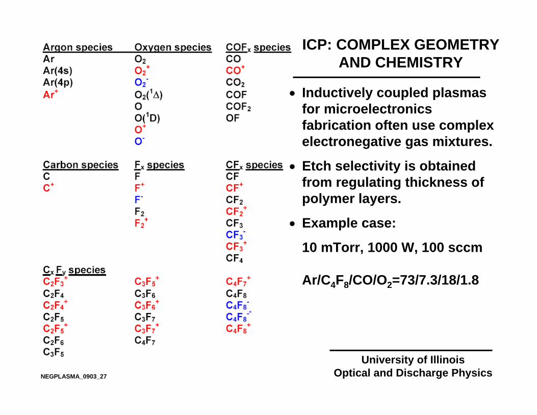
ICP: COMPLEX GEOMETRY AND CHEMISTRY
University of IllinoisOptical and Discharge PhysicsNEGPLASMA_0903_27
• Inductively coupled plasmas for microelectronics fabrication often use complex electronegative gas mixtures.
• Etch selectivity is obtained from regulating thickness of polymer layers.
• Example case:
10 mTorr, 1000 W, 100 sccm
Ar/C4F8/CO/O2=73/7.3/18/1.8
University of IllinoisOptical and Discharge PhysicsNEGPLASMA_0903_28
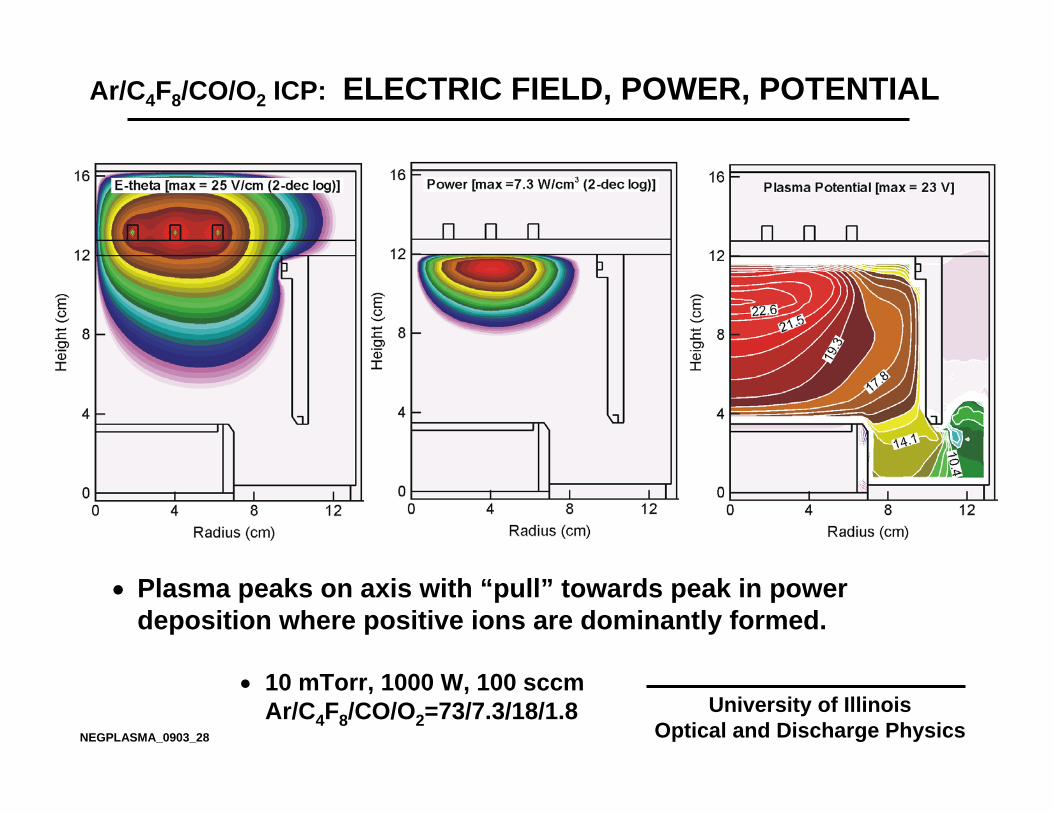
• Plasma peaks on axis with “pull” towards peak in power deposition where positive ions are dominantly formed.
Ar/C4F8/CO/O2 ICP: ELECTRIC FIELD, POWER, POTENTIAL
• 10 mTorr, 1000 W, 100 sccm Ar/C4F8/CO/O2=73/7.3/18/1.8

University of IllinoisOptical and Discharge PhysicsNEGPLASMA_0903_29
• [e] near maximum in plasma potential. Negative ions “shield” positive ions at their low and high values. Catephoresis displaces negative ions towards boundaries.
Ar/C4F8/CO/O2 ICP: [e], [N+], [N-]
• 10 mTorr, 1000 W, 100 sccm Ar/C4F8/CO/O2=73/7.3/18/1.8

University of IllinoisOptical and Discharge PhysicsNEGPLASMA_0903_30
• Negative ions, trapped in the plasma, flow towards peak of plasma potential where they undergo ion-ion neutralization. Positive ions largely flow to boundaries.
Ar/C4F8/CO/O2 ICP: [Ar+], [F-]
• 10 mTorr, 1000 W, 100 sccm Ar/C4F8/CO/O2=73/7.3/18/1.8

University of IllinoisOptical and Discharge PhysicsNEGPLASMA_0903_31
• C4F8-, being heavier and less mobile, is more susceptible to being trapped in small local extrema of the plasma potential.
• These “trapping zones” are often the precursor to dust particle formation.
Ar/C4F8/CO/O2 ICP: [C4F8-]
• 10 mTorr, 1000 W, 100 sccm Ar/C4F8/CO/O2=73/7.3/18/1.8

University of IllinoisOptical and Discharge Physics
MOMENTUM TRANSFER: CATAPHORESIS
NEGPLASMA_0903_32
• Due to the large Coulomb scattering cross section, there is efficient momentum transfer between positive and negative ions.
• Large flux of positive ions moving towards boundaries “pushes” negative ions in the same direction.
• This is a particularly important process when negative ions are charged dust particles (“ion-drag”)
( )++−+
−
−+= vvσN....dt
dM
rrrr
ΦΦ

University of IllinoisOptical and Discharge Physics
CATAPHORESIS IN ICPs
NEGPLASMA_0903_33
• When the flux of positive ions is large and electronegativity (N-/N+) small, momentum transfer from N+
to N- can be important.
• Ar/Cl2=50/50, 100 sccm, 500 W, 10 mTorr

University of IllinoisOptical and Discharge Physics
CATAPHORESIS IN ICPs
NEGPLASMA_0903_34
• The Coulomb momentum transfer cross section between N- and N+ scales inversely with energy.
• Ion drag is therefore sensitive to temperature and speed of interaction; decreasing in importance as both increase.
• Ar/Cl2=50/50, 100 sccm, 500 W, 10 mTorr
( )
jiI
2ij
vvkT23k
23
cm
rr−+=
×= −
−
ijij
ij
,Kln.σ
ηΨ
ΨΛ
21
1095 6

CHARGING DAMAGE IN MICROELECTRONICS FABRICATION
University of IllinoisOptical and Discharge Physics
University of IllinoisOptical and Discharge Physics
• In microelectronics fabrication, trenches are etched into silicon substrates
• Ions arrive with vertical trajectories. Electrons arrive with broad thermal trajectories.
• The top of the trench is charged negative; the bottom positive.
• Ion trajectories are perturbed by electric fields in the trench.
• Plasma induced damage such as notching, bowing, microtrenching can then occur.
• Charge in the bottom of the trench can be neutralized accelerating negative ions into the wafer
+ + + +
- - - - - - - -Bowing
MicroTrenching
Notching
Induced Currents
Positive Ions
NEGPLASMA_0903_35

PULSED PLASMAS FOR NEGATIVE ION EXTRACTION
University of IllinoisOptical and Discharge Physics
• During cw operation of ICPs, negative ions cannot escape the plasma.
• By pulsing the plasma (turn power on-off), during the off period (the “afterglow”)…
• The electron temperature decreases
• Plasma potential decreases• Negative ion formation
(usually) increases• Negative ions can escape…
NEGPLASMA_0903_36

• The ideal gas mixture is low attaching at high Te (power-on) and highly attaching at low Te(power-off)
• Ar/Cl2 mixtures have these properties.
• Dissociative attachment cross section peaks at thermal energies.
e + Cl2 → Cl + Cl-
• Rapid attachment occurs in the afterglow. • Electron impact cross
sections for Cl2.Ref: J. Olthoff, Appl. J. Phys. Chem. Ref.
Data, 28, 130 (1999)University of Illinois
Optical and Discharge Physics
PULSED PLASMAS: Ar/Cl2 GAS CHEMISTRIES
NEGPLASMA_0903_37
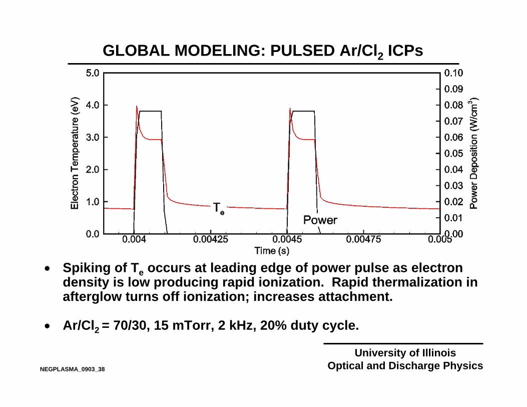
• Spiking of Te occurs at leading edge of power pulse as electron density is low producing rapid ionization. Rapid thermalization in afterglow turns off ionization; increases attachment.
• Ar/Cl2 = 70/30, 15 mTorr, 2 kHz, 20% duty cycle.
University of IllinoisOptical and Discharge Physics
GLOBAL MODELING: PULSED Ar/Cl2 ICPs
NEGPLASMA_0903_38
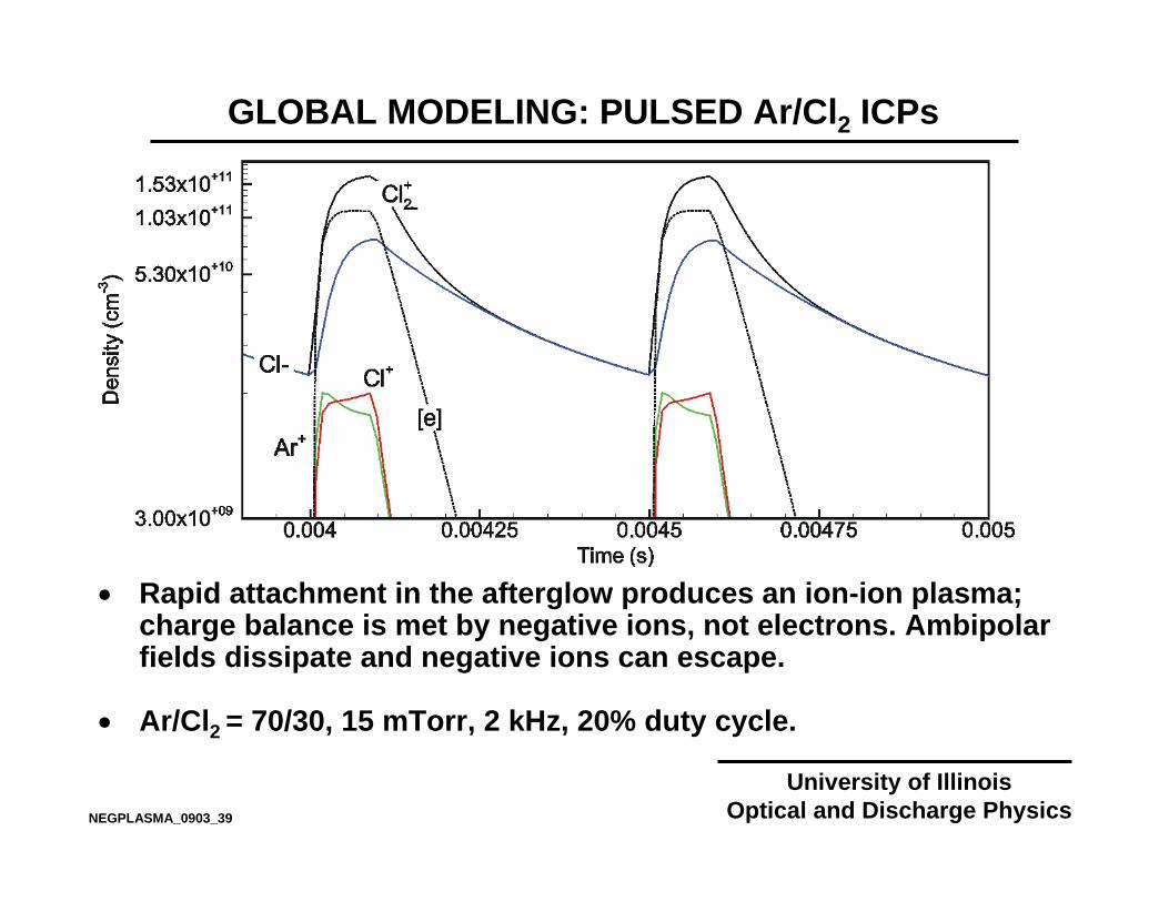
• Rapid attachment in the afterglow produces an ion-ion plasma; charge balance is met by negative ions, not electrons. Ambipolarfields dissipate and negative ions can escape.
• Ar/Cl2 = 70/30, 15 mTorr, 2 kHz, 20% duty cycle.
University of IllinoisOptical and Discharge Physics
GLOBAL MODELING: PULSED Ar/Cl2 ICPs
NEGPLASMA_0903_39

REACTOR AND CONDITIONS
University of IllinoisOptical and Discharge Physics
Quartz Window
Standard Lower Electrode Insulator
Electrode Extension
Upper Electrode Assembly5-turn spiral coil
Gas Feed
Pump Port
25 cm
11.6
cm
16.5 cm
4.05
cm
• Inlet gas flow rate : 20 sccm• Ar, Ar/Cl2 = 80/20
• Peak input power : 300 W• Pulse repetition frequency : 10 kHz• Pressure : 20 mTorr
• Simulations were performed in a GECRC
NEGPLASMA_0903_40

2-D DYNAMICS IN Ar/Cl2 :PLASMA POTENTIAL AND Cl- FLUX VECTORS
University of IllinoisOptical and Discharge Physics
University of IllinoisOptical and Discharge Physics
• Ar/Cl2 = 80/20, 20 mTorr, 300 W,10 kHz/50%
• As the pulse begins, the peak plasma potential migrates to under the coils.
• As the steady state is reached, the peak plasma potential moves towards the center.
• Cl- flux vectors point towards the peak plasma potential when plasma potential is large.
• It takes about 25 µs for the ions to move from periphery to the center.
• When the plasma is turned off, Cl-flux vectors reverse, pointing towards boundaries.
35 V-3 V
Animation SlideNEGPLASMA_0903_42

2-D DYNAMICS IN Ar/Cl2 : Cl- DENSITY
University of IllinoisOptical and Discharge Physics
University of IllinoisOptical and Discharge Physics
• During power on, the plasma potential peaks thereby "compressing" the [Cl-]
• At steady state, [Cl-] "rebounds" as the plasma potential decreases
• Due to inertia, [Cl-] does not respond to changes in plasma potential immediately.
• When the plasma is turned off, the [Cl-] increases due to a higher rate of dissociative attachment at low Te.
• Later, the plasma potential falls and [Cl-] spreads
• Ar/Cl2 = 80/20, 20 mTorr, 300 W,10 kHz/50%
3 x 1011 cm-31 x 109 cm-3
Animation SlideNEGPLASMA_0903_41

[e] vs PULSE REPETITION FREQUENCY (PRF)
University of IllinoisOptical and Discharge Physics
University of IllinoisOptical and Discharge Physics
• Ar/Cl2 = 80/20, 20 mTorr, 300 W,10 kHz, 50% duty cycle
• Non-monotonic behavior in peak [e].
• Lower PRF results in higher rate of dissociation due to higher Te producing less dissociative attachment.
Time (µs)0 50 100 150 200
2
4
6
8
10
0
Ele
ctro
n D
ensi
ty (1
011
cm-3
)
5 kHz
5
20 20 20 20
10 10
Power On5 kHz
10 kHz20 kHz
NEGPLASMA_0903_43

University of IllinoisOptical and Discharge Physics
University of IllinoisOptical and Discharge Physics
• [Cl-] increases at plasma turn on as the Cl- ions move to the center of plasma; and then decrease as recombination occurs.
• When power is removed, [Cl-] increases with drop in Te, and then decreases as Cl- diffuses to walls.
[Cl-] vs PULSE REPETITION FREQUENCY (PRF)
0 50 100 150 200
0.5
1
1.5
2
0
Time (µs)
Cl-
Den
sity
(101
1 cm
-3)
5 kHz10
10
20 20
20
Power On5 kHz
10 kHz20 kHz
• Ar/Cl2 = 80/20, 20 mTorr, 300 W,10 kHz, 50% duty cycle
NEGPLASMA_0903_44

0 50 100 150 200Time (µs)
0
5
10
15
20
Pos
itive
ion
and
el
ectro
n flu
x (1
015
cm-2
s-1
)
Cl-
flux(
1014
cm
-2 s
-1)
0
2
4
6
8
Cl-Cl-
Electron and Positive ion flux
+ +e e
FLUXES TO SUBSTRATE: DUTY CYCLE
University of IllinoisOptical and Discharge Physics
University of IllinoisOptical and Discharge Physics• Ar/Cl2 = 80/20, 20 mTorr, 300 W, 10 kHz
• A finite time is required to transition to ion-ion plasma in the afterglow with a low plasma potential.
• For a give repetition rate, smaller duty cycles (longer afterglow) produces longer pulses of Cl- fluxes to the substrate.
• Duty cycle : 10%
0 50 100 150 200Time (µs)
0
10
20
30
40
Pos
itive
ion
and
el
ectro
n flu
x (1
015
cm-2
s-1
)
Cl-
flux(
1014
cm
-2 s
-1)
0
2
4
6
8
10
Cl-Cl-
+ +e e
Electron and Positive ion flux
• Duty cycle : 50%
NEGPLASMA_0903_45

ELECTRONEGATIVE PLASMAS: ATMOSPHERIC PRESSURE
University of IllinoisOptical and Discharge Physics
University of IllinoisOptical and Discharge Physics
• The vast majority of atmospheric pressure plasmas having significant electronegativity are pulsed, transient or filamentary.
• What changes at atmospheric pressure?
• Availability of 3rd body increases rates of association reactions; and is the basis of excimer formation.
• Kinetics are “local” in that transport for negative is not terribly important.
• Due to higher gas densities, rates of attachment are higher, making transitions to ion-ion plasmas more rapid.
• “Stationary” negative ions provide local shielding of positive ions, particularly in afterglow situations.
( )
νhClXe
MBXeClMClXe
++
+↓
→++ −+
NEGPLASMA_0903_46
University of IllinoisOptical and Discharge Physics
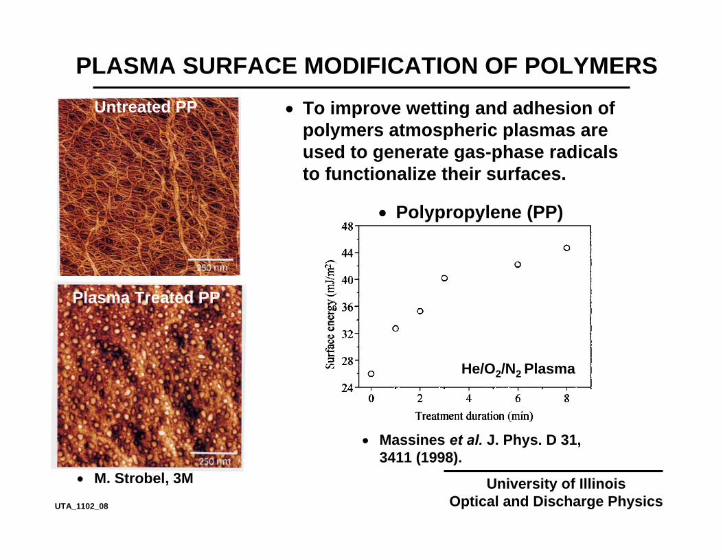
PLASMA SURFACE MODIFICATION OF POLYMERS• To improve wetting and adhesion of
polymers atmospheric plasmas are used to generate gas-phase radicals to functionalize their surfaces.
Untreated PP
Plasma Treated PP
• M. Strobel, 3M
• Polypropylene (PP)
He/O2/N2 Plasma
• Massines et al. J. Phys. D 31, 3411 (1998).
UTA_1102_08

University of IllinoisOptical and Discharge Physics
FUNCTIONALIZATION OF POLYPROPYLENE
• Untreated PP is hydrophobic.
• Increases in surface energy by plasma treatment are attributed to the functionalization of the surface with hydrophilic groups.
• Carbonyl (-C=O) • Alcohols (C-OH)
• Peroxy (-C-O-O) • Acids ((OH)C=O)
• The degree of functionalization depends on process parameters such as gas mix, energy deposition and relative humidity (RH).
• At sufficiently high energy deposition, erosion of the polymer occurs.
UTA_1102_13

University of IllinoisOptical and Discharge Physics
REACTION PATHWAY
RAJESH_AVS_02_05
C C C C C C C C C
C C C C C C C C C C
O
HOH
O||
OH, O
C C C C C C C C C C C
LAYER 1
LAYER 2
LAYER 3
H
OH, H2O
OH
OHO2
O2
HUMID-AIR PLASMA
BOUNDARY LAYER
POLYPROPYLENE
H2O
e e
H OH
N2
e e
N NO2
O O
e e
O2O3
O2NO
NO

University of IllinoisOptical and Discharge Physics
POLYMER TREATMENT APPARATUS
RAJESH_AVS_02_04A
HIGH-VOLTAGEPOWER SUPPLY
FEED ROLLGROUNDEDELECTRODE
COLLECTORROLL
PLASMA
~
SHOEELECTRODE
POWERED
TYPICAL PROCESS CONDITIONS:
Gas gap : a few mmApplied voltage : 10-20 kV at a few 10s kHzEnergy deposition : 0.1 - 1.0 J cm-2Residence time : a few sWeb speed : 10 - 200 m/min

University of IllinoisOptical and Discharge Physics
COMMERCIAL CORONA PLASMA EQUIPMENT
RAJESH_AVS_02_04
Tantec Inc.

University of IllinoisOptical and Discharge Physics
• 2-d rectilinear or cylindrical unstructured mesh• Implicit drift-diffusion for charged and neutral species• Poisson’s equation with volume and surface charge, and
material conduction.• Circuit model• Electron energy equation coupled with Boltzmann solution
for electron transport coefficients• Optically thick radiation transport with photoionization• Secondary electron emission by impact• Thermally enhanced electric field emission of electrons• Surface chemistry.• Monte Carlo Simulation for secondary electrons• Compressible Navier Stokes for hydrodynamic flow• Maxwell Equations in frequency domain
HIGH PRESSURE PLASMA SIMULATION: non-PDPSIM
NEGPLASMA_0903_47
University of IllinoisOptical and Discharge Physics
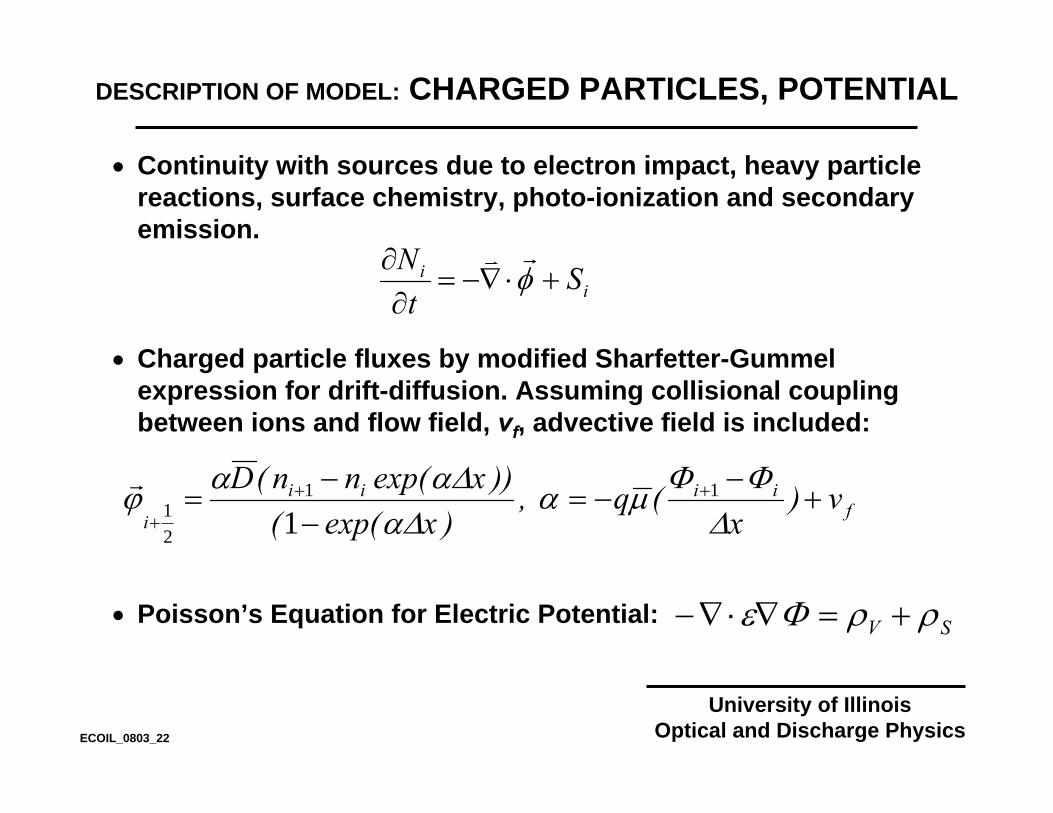
DESCRIPTION OF MODEL: CHARGED PARTICLES, POTENTIAL
• Continuity with sources due to electron impact, heavy particle reactions, surface chemistry, photo-ionization and secondary emission.
• Charged particle fluxes by modified Sharfetter-Gummelexpression for drift-diffusion. Assuming collisional coupling between ions and flow field, vf, advective field is included:
• Poisson’s Equation for Electric Potential:
ii StN
+⋅∇−=∂
∂ φrv
fiiii
iv)
x(q,
)xexp(())xexp(nn(D
+−
−=−
−= ++
+ ∆ΦΦµα
∆α∆ααϕ 11
21 1
r
SV ρρΦε +=∇⋅∇−
ECOIL_0803_22
University of IllinoisOptical and Discharge Physics
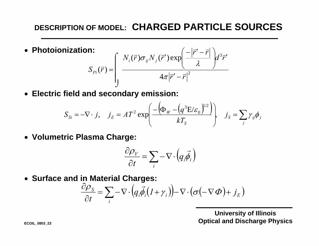
DESCRIPTION OF MODEL: CHARGED PARTICLE SOURCES
• Photoionization:
• Electric field and secondary emission:
• Volumetric Plasma Charge:
• Surface and in Material Charges:
( )∑ ⋅∇−=∂
∂
iii
V qt
φρ r
( )( ) ( )( )∑ +∇−⋅∇−+⋅∇−=∂
∂
iEiii
S j1qt
Φσγφρ r
( )( ) ∑=⎟⎟⎠
⎞⎜⎜⎝
⎛ −Φ−=⋅−∇=
jjijS
S
WESi j
kTqATjjS φγε ,E/exp,
1/20
32
⎮⎮⎮
⌡
⌠
−′
′⎟⎟⎠
⎞⎜⎜⎝
⎛ −′−′
= 2
3
4
exp)()()(
rr
rdrr
rNrNrS
jiji
Pi vv
vvv
vv
v
π
λσ
ECOIL_0803_23

University of IllinoisOptical and Discharge Physics
DESCRIPTION OF MODEL:ELECTRON ENERGY, TRANSPORT COEFFICIENTS
• Electron energy equation implicitly integrated using Successive-Over-Relaxation:
• Electron transport coefficients obtained from 2-term spherical harmonic expansion of Boltzmann’s Equation.
• Ion transport coefficients obtained from tabulated values from the literature or using conventional approximation techniques.
( )e
ieiie
e qj,T25NnEj
tn φλεϕκ∂
ε∂ rrrr=⎟
⎠⎞
⎜⎝⎛ ∇−⋅∇−−⋅= ∑
ECOIL_0803_25
University of IllinoisOptical and Discharge Physics
• Transport of energetic secondary electrons is addressed with a Monte Carlo Simulation.
• MCS is periodically executed to provide electron impact source functions for continuity equations for charged and neutral particles.
• Algorithms in MCS account for large dynamic range in mesh resolution, electric field, and reactant densities.
DESCRIPTION OF MODEL: SECONDARY ELECTRONS-MONTE CARLO SIMULATION
ECOIL_0803_27
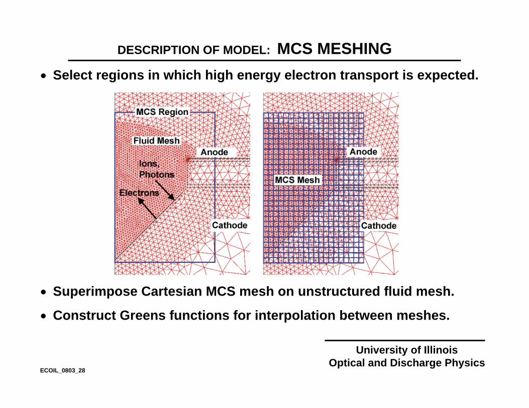
• Select regions in which high energy electron transport is expected.
• Superimpose Cartesian MCS mesh on unstructured fluid mesh.
• Construct Greens functions for interpolation between meshes.
University of IllinoisOptical and Discharge Physics
DESCRIPTION OF MODEL: MCS MESHING
ECOIL_0803_28

University of IllinoisOptical and Discharge Physics
ELECTROMAGNETICS MODEL
• The wave equation is solved in the frequency domain.
• All quantities are complex for to account for finite collision frequencies.
• Solved using method of Successive-over-Relaxation
( ) ( )tJE
tEE antenna
∂+∂
+∂
∂=⎟⎟
⎠
⎞⎜⎜⎝
⎛∇⋅∇
σεµ
2
2
1
ECOIL_0803_30

University of IllinoisOptical and Discharge Physics
COMPRESSIBLE NAVIER STOKES
• Fluid averaged values of mass density, mass momentum and thermal energy density obtained in using unsteady algorithms.
)pumps,inlets()v(t
+⋅−∇=rρ
∂ρ∂
( ) ( ) ( ) ∑+⋅∇−⋅∇−∇=i
iii ENqvvNkTtv vrrr
µρ∂ρ∂
( ) ( ) ∑ ∑ ⋅+−⋅∇++∇−−∇=i i
iiifipp EjHRvPTcvTtTc rrr ∆ρκ
∂ρ∂
ECOIL_0803_31

University of IllinoisOptical and Discharge Physics
• Transport equations are implicitly solved using Successive-Over-Relaxation:
• Surface chemistry is addressed using “flux-in/flux-out” boundary conditions with reactive sticking coefficients
( ) ( ) ( )SV
T
iTifii SS
NttNNDvtNttN ++⎟
⎟⎠
⎞⎜⎜⎝
⎛⎟⎟⎠
⎞⎜⎜⎝
⎛ +∇−⋅∇−=+
∆∆ r
DESCRIPTION OF MODEL: NEUTRAL PARTICLE UPDATE
( )∑ ⋅∇=j
ijjSiS γφr
ECOIL_0803_26

ATMOSPHERIC PRESSURE LINEAR CORONA
University of IllinoisOptical and Discharge Physics
University of IllinoisOptical and Discharge Physics
• Demonstrate concepts of pulsed atmospheric pressure electronegative plasma with linear corona discharge as used in polymer functionalization.
• Device is functionally a dielectric barrier discharge. Discharge is initiated by field emission from cathode.
• Dry Air N2/O2 = 80/20, -15 kV, 2 mm gap
NEGPLASMA_0903_48

LINEAR CORONA: NEGATIVE ION DYNAMICS
University of IllinoisOptical and Discharge Physics
University of IllinoisOptical and Discharge PhysicsNEGPLASMA_0903_54
• Dissociative attachment (e + O2 → O- + O) has a 5 eV threshold energy. Occurs dominantly in high E/N regions.
• 3-body non-dissociative attachment (e + O2 + M → O2- + M)
has no threshold. Occurs with frequency 4 x 10⁸ s-1 (2 ns lifetime) in atmospheric pressure air.
• O2- charge exchanges with O (O2
- + O → O2- + O- , k = 1.5 x 10-
10 cm3 s-1). With maximum O density (4 x 1016 cm-3), lifetime is 0.1 µs (not very important).
• O- associates by deattachment with O (O- + O → O2 + e , k = 2 x 10⁻¹⁰ cm3 s-1). With maximum O density (4 x 1016 cm-3), lifetime is 0.1 µs (not very important).
• Negative ions are fairly stable (and immobile) until ion-ion neutralization [k(effective-2 body)= 5 x 10⁻⁶ cm3 s-1, lifetime 10’s ns].
LINEAR CORONA: [e], E/N
University of IllinoisOptical and Discharge Physics
University of IllinoisOptical and Discharge PhysicsNEGPLASMA_0903_49
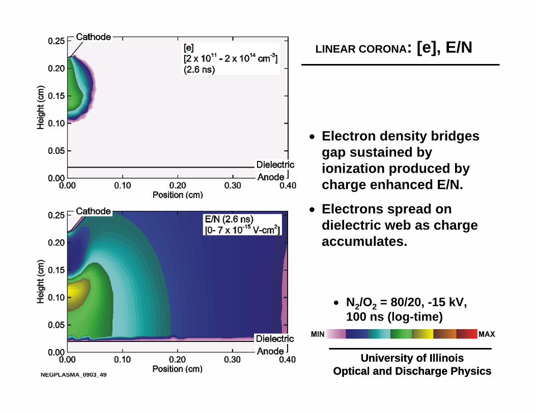
• N2/O2 = 80/20, -15 kV, 100 ns (log-time)
• Electron density bridges gap sustained by ionization produced by charge enhanced E/N.
• Electrons spread on dielectric web as charge accumulates.

LINEAR CORONA: [e], E/N
University of IllinoisOptical and Discharge Physics
University of IllinoisOptical and Discharge Physics
• Electron density bridges gap sustained by ionization produced by charge enhanced E/N.
• Electrons spread on dielectric web as charge accumulates.
NEGPLASMA_0903_50
Animation Slide
• N2/O2 = 80/20, -15 kV, 100 ns (log-time)

LINEAR CORONA: POTENTIAL, CHARGE
University of IllinoisOptical and Discharge Physics
University of IllinoisOptical and Discharge Physics
• Charge density sustains E/N at front of avalanche.
• Electric potential is shielded from the gap by charging of the dielectric web.
NEGPLASMA_0903_51
• N2/O2 = 80/20, -15 kV, 100 ns (log-time)

LINEAR CORONA: POTENTIAL, CHARGE
University of IllinoisOptical and Discharge Physics
University of IllinoisOptical and Discharge PhysicsNEGPLASMA_0903_52
Animation Slide
• N2/O2 = 80/20, -15 kV, 100 ns (log-time)
• Charge density sustains E/N at front of avalanche.
• Electric potential is shielded from the gap by charging of the dielectric web.
LINEAR CORONA: TOTAL POSITIVE ION DENSITY
University of IllinoisOptical and Discharge Physics
University of IllinoisOptical and Discharge PhysicsNEGPLASMA_0903_53
Animation Slide
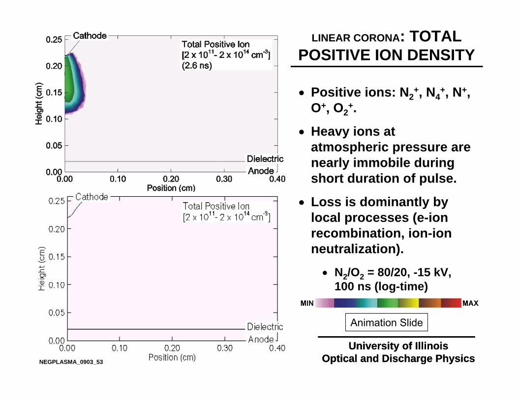
• N2/O2 = 80/20, -15 kV, 100 ns (log-time)
• Positive ions: N2+, N4
+, N+, O+, O2
+.
• Heavy ions at atmospheric pressure are nearly immobile during short duration of pulse.
• Loss is dominantly by local processes (e-ion recombination, ion-ion neutralization).

LINEAR CORONA: NEGATIVE IONS O-, O2
-
University of IllinoisOptical and Discharge Physics
University of IllinoisOptical and Discharge PhysicsNEGPLASMA_0903_55
• N2/O2 = 80/20, -15 kV, 100 ns (log-time)
• Rapid conversion of e to O2
- by 3-body processes produces an ion-ion plasma in afterglow.
• Nearly immobile negative ions (µ=2 cm2/V-s, vdrift = 105 cm/s) are largely consumed where formed by ion-ion neutralization.

LINEAR CORONA: NEGATIVE IONS O-, O2
-
University of IllinoisOptical and Discharge Physics
University of IllinoisOptical and Discharge PhysicsNEGPLASMA_0903_56
Animation Slide
• N2/O2 = 80/20, -15 kV, 100 ns (log-time)
• Rapid conversion of e to O2
- by 3-body processes produces an ion-ion plasma in afterglow.
• Nearly immobile negative ions (µ=2 cm2/V-s, vdrift = 105 cm/s) are largely consumed where formed by ion-ion neutralization.
CONCLUDING REMARKS
University of IllinoisOptical and Discharge Physics
University of IllinoisOptical and Discharge PhysicsNEGPLASMA_0903_57
• As you develop you models for electronegative plasmas (or any type plasma)…
• Construct your models as GENERALLY as possible. Never, never, never hardwire any species or chemical reaction mechanism in your code.
• Read all options, species, mechanisms as input from WELL MAINTAINED AND DOCUMENTED DATABASES.
• Develop STANDARDS for input, output, use of databases and visualization which ALL of your codes obey.
• DOCUMENT, DOCUMENT, DOCUMENT!!! Every input-variable, every output-parameter, every process. Have “official” versions.
• ARCHIVE, ARCHIVE, ARCHIVE!!! Example cases, documentation, best practice, official version.…A computer knowledgeable person should be able to run cases in a day.

University of IllinoisOptical and Discharge PhysicsNEGPLASMA_0903_58
ACKNOWLEDGEMENTS
Postdoctoral Research Fellows:
Dr. Alex VasenkovDr. Wenli Collison
Graduate Students (past and present)
Pramod SubramoniumRajesh DoraiD. Shane Stafford
Funding Agencies
National Science FoundationSemiconductor Research Corp.3M Inc.