Embed Size (px)
Citation preview
1
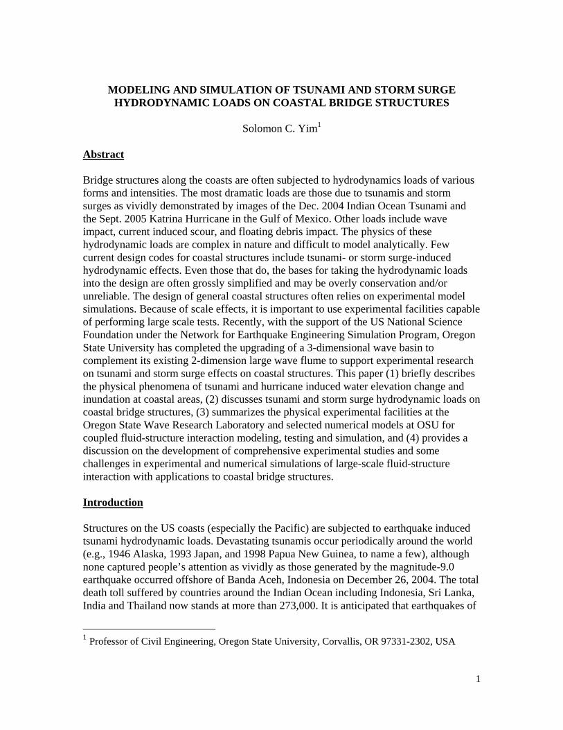
MODELING AND SIMULATION OF TSUNAMI AND STORM SURGE HYDRODYNAMIC LOADS ON COASTAL BRIDGE STRUCTURES
Solomon C. Yim1
Abstract Bridge structures along the coasts are often subjected to hydrodynamics loads of various forms and intensities. The most dramatic loads are those due to tsunamis and storm surges as vividly demonstrated by images of the Dec. 2004 Indian Ocean Tsunami and the Sept. 2005 Katrina Hurricane in the Gulf of Mexico. Other loads include wave impact, current induced scour, and floating debris impact. The physics of these hydrodynamic loads are complex in nature and difficult to model analytically. Few current design codes for coastal structures include tsunami- or storm surge-induced hydrodynamic effects. Even those that do, the bases for taking the hydrodynamic loads into the design are often grossly simplified and may be overly conservation and/or unreliable. The design of general coastal structures often relies on experimental model simulations. Because of scale effects, it is important to use experimental facilities capable of performing large scale tests. Recently, with the support of the US National Science Foundation under the Network for Earthquake Engineering Simulation Program, Oregon State University has completed the upgrading of a 3-dimensional wave basin to complement its existing 2-dimension large wave flume to support experimental research on tsunami and storm surge effects on coastal structures. This paper (1) briefly describes the physical phenomena of tsunami and hurricane induced water elevation change and inundation at coastal areas, (2) discusses tsunami and storm surge hydrodynamic loads on coastal bridge structures, (3) summarizes the physical experimental facilities at the Oregon State Wave Research Laboratory and selected numerical models at OSU for coupled fluid-structure interaction modeling, testing and simulation, and (4) provides a discussion on the development of comprehensive experimental studies and some challenges in experimental and numerical simulations of large-scale fluid-structure interaction with applications to coastal bridge structures. Introduction Structures on the US coasts (especially the Pacific) are subjected to earthquake induced tsunami hydrodynamic loads. Devastating tsunamis occur periodically around the world (e.g., 1946 Alaska, 1993 Japan, and 1998 Papua New Guinea, to name a few), although none captured people’s attention as vividly as those generated by the magnitude-9.0 earthquake occurred offshore of Banda Aceh, Indonesia on December 26, 2004. The total death toll suffered by countries around the Indian Ocean including Indonesia, Sri Lanka, India and Thailand now stands at more than 273,000. It is anticipated that earthquakes of
1 Professor of Civil Engineering, Oregon State University, Corvallis, OR 97331-2302, USA
2
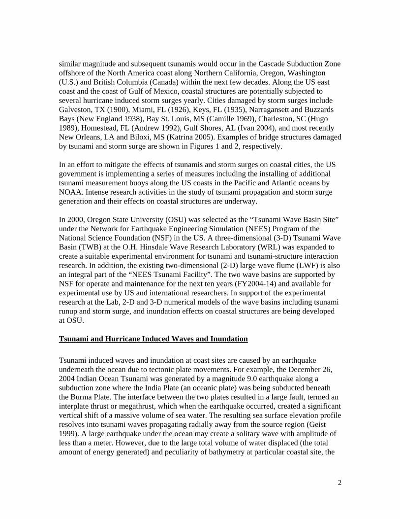
similar magnitude and subsequent tsunamis would occur in the Cascade Subduction Zone offshore of the North America coast along Northern California, Oregon, Washington (U.S.) and British Columbia (Canada) within the next few decades. Along the US east coast and the coast of Gulf of Mexico, coastal structures are potentially subjected to several hurricane induced storm surges yearly. Cities damaged by storm surges include Galveston, TX (1900), Miami, FL (1926), Keys, FL (1935), Narragansett and Buzzards Bays (New England 1938), Bay St. Louis, MS (Camille 1969), Charleston, SC (Hugo 1989), Homestead, FL (Andrew 1992), Gulf Shores, AL (Ivan 2004), and most recently New Orleans, LA and Biloxi, MS (Katrina 2005). Examples of bridge structures damaged by tsunami and storm surge are shown in Figures 1 and 2, respectively. In an effort to mitigate the effects of tsunamis and storm surges on coastal cities, the US government is implementing a series of measures including the installing of additional tsunami measurement buoys along the US coasts in the Pacific and Atlantic oceans by NOAA. Intense research activities in the study of tsunami propagation and storm surge generation and their effects on coastal structures are underway. In 2000, Oregon State University (OSU) was selected as the “Tsunami Wave Basin Site” under the Network for Earthquake Engineering Simulation (NEES) Program of the National Science Foundation (NSF) in the US. A three-dimensional (3-D) Tsunami Wave Basin (TWB) at the O.H. Hinsdale Wave Research Laboratory (WRL) was expanded to create a suitable experimental environment for tsunami and tsunami-structure interaction research. In addition, the existing two-dimensional (2-D) large wave flume (LWF) is also an integral part of the “NEES Tsunami Facility”. The two wave basins are supported by NSF for operate and maintenance for the next ten years (FY2004-14) and available for experimental use by US and international researchers. In support of the experimental research at the Lab, 2-D and 3-D numerical models of the wave basins including tsunami runup and storm surge, and inundation effects on coastal structures are being developed at OSU. Tsunami and Hurricane Induced Waves and Inundation Tsunami induced waves and inundation at coast sites are caused by an earthquake underneath the ocean due to tectonic plate movements. For example, the December 26, 2004 Indian Ocean Tsunami was generated by a magnitude 9.0 earthquake along a subduction zone where the India Plate (an oceanic plate) was being subducted beneath the Burma Plate. The interface between the two plates resulted in a large fault, termed an interplate thrust or megathrust, which when the earthquake occurred, created a significant vertical shift of a massive volume of sea water. The resulting sea surface elevation profile resolves into tsunami waves propagating radially away from the source region (Geist 1999). A large earthquake under the ocean may create a solitary wave with amplitude of less than a meter. However, due to the large total volume of water displaced (the total amount of energy generated) and peculiarity of bathymetry at particular coastal site, the
3
resulting tsunami runup height could be tens of meters (including astronomical tide), causing major structural damage to bridge structures.
Severe tropical cyclone (called typhoon in the Western Pacific Ocean and hurricane in North Atlantic, Caribbean and Gulf of Mexico) induces storm surge generated by barometric pressure drop, and storm waves generated by extreme high-speed winds. The water elevation at a coastal location nearshore contains four components: (1) the storm surge, (2) storm waves, (3) wave setup and (4) astronomical tide (Cheung, et al. 2003). Storm surge is the long gravity wave generated by the large volume of water under the hurricane attracted by the negative barometric pressure. This large volume of water, with horizontal length scales similar to the size of the generating hurricane and a height of up to 1 meter, induces long waves similar to that of a tsunami. The radius of maximum winds provides an important scaling parameter for storm-surge estimations. A crude approximate measure for the wave length of the long gravity surge wave is four times the radius of maximum winds. The hurricane winds create high frequency, short storm waves, which are similar to the wind waves one normally observes under ordinary situation. The wave setup is the increase in mean water elevation due to bundling up of the storm waves at the shoreline. Hurricane size, translation speed and angle of attack to the coast, together with local offshore bathometry and inland topography all play significant roles in determining the resulting characteristics of the local water elevation and the resulting inundation (Jelesnianski, et al. 1992).
While the generation sources between tsunami and the storm surge are different, the physical characteristics of their wave propagation (in deep water), nonlinear transformation (in shallow water) and runup (land inundation) are identical. analytical and numerical models for each of these phases have been developed. Numerical codes for storm surge SSM (Storm Surge Model, Mastenbroek et al. 1993), wave in open ocean WAM (WAve Model, Komen et al. 1994), coastal wave transformation SWAN (Simulating WAve Nearshore, Booij et al. 1999), and surf-zone processes and runup COULWAVE (Cornell University Long WAVE, Lynette et al. 2002) are representative examples. These models have been coupled together to form a source to shore water elevation and inundation prediction for emergency management in the state of Hawaii (Cheung, et al. 2003). Hydrodynamic Loads on Bridge Structures The hydrodynamic loads due to tsunami and storm surge on a coastal bridge include hydrostatic pressure, buoyancy force, fluid flow drag and surge impingement. Other load effects induced by tsunami and storm surge including foundation scour and impact due to waterborne debris. These loads may induce large structural deformation, yielding, fracture, and collapse and/or dislodgement of coastal structures from their bases. Estimates of design values of direct hydrodynamic loads due river flood and wave
4
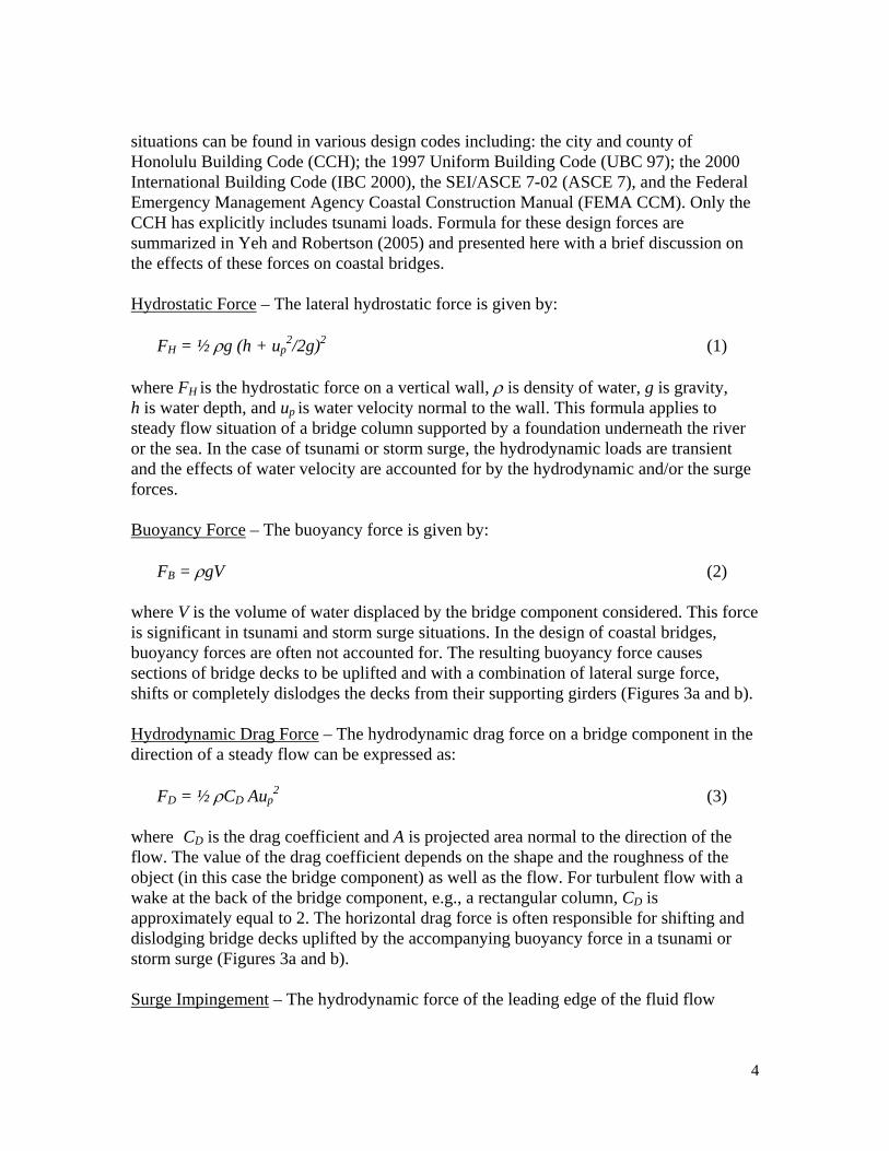
situations can be found in various design codes including: the city and county of Honolulu Building Code (CCH); the 1997 Uniform Building Code (UBC 97); the 2000 International Building Code (IBC 2000), the SEI/ASCE 7-02 (ASCE 7), and the Federal Emergency Management Agency Coastal Construction Manual (FEMA CCM). Only the CCH has explicitly includes tsunami loads. Formula for these design forces are summarized in Yeh and Robertson (2005) and presented here with a brief discussion on the effects of these forces on coastal bridges. Hydrostatic Force – The lateral hydrostatic force is given by: FH = ½ ρg (h + up
2/2g)2 (1) where FH is the hydrostatic force on a vertical wall, ρ is density of water, g is gravity, h is water depth, and up is water velocity normal to the wall. This formula applies to steady flow situation of a bridge column supported by a foundation underneath the river or the sea. In the case of tsunami or storm surge, the hydrodynamic loads are transient and the effects of water velocity are accounted for by the hydrodynamic and/or the surge forces. Buoyancy Force – The buoyancy force is given by: FB = ρgV (2) where V is the volume of water displaced by the bridge component considered. This force is significant in tsunami and storm surge situations. In the design of coastal bridges, buoyancy forces are often not accounted for. The resulting buoyancy force causes sections of bridge decks to be uplifted and with a combination of lateral surge force, shifts or completely dislodges the decks from their supporting girders (Figures 3a and b). Hydrodynamic Drag Force – The hydrodynamic drag force on a bridge component in the direction of a steady flow can be expressed as: FD = ½ ρCD Aup
2 (3) where CD is the drag coefficient and A is projected area normal to the direction of the flow. The value of the drag coefficient depends on the shape and the roughness of the object (in this case the bridge component) as well as the flow. For turbulent flow with a wake at the back of the bridge component, e.g., a rectangular column, CD is approximately equal to 2. The horizontal drag force is often responsible for shifting and dislodging bridge decks uplifted by the accompanying buoyancy force in a tsunami or storm surge (Figures 3a and b). Surge Impingement – The hydrodynamic force of the leading edge of the fluid flow

5
acting on per unit area of a bridge structure due to tsunami or storm surge the following expression: FH = CIρgh2 (4) where CI is the surge impingement coefficient and h is the height of the surging flow. Currently the surge impingement force is not currently considered in the design codes mentioned above except for CCH, which gives a value of CI = 4.5. According to Yeh and Robertson (2005), this value is quite conservative and may excessively over estimate the true maximum impingement force. Although the surge impingement force may be quite large, its true effects on bridge structures are unknown. A large number of experimental and/or numerical simulations need to be performed to provide a statistic basis for future analysis and design code development. Tsunami and Storm Surge Scour – Scour of supporting material at the base of a bridge pier due to tsunami or storm surge differs from the ordinary case of bridge scour, which occurs gradually caused by periodic waves and steady current loads. In a tsunami or storm surge, the leading wave may scour away much of the supporting materials around the base of a bridge column and weaken the foundation so much that the pier fails under the subsequent fluid drag load. While the effects of scour due to tsunami and/or storm surge can be easily observed for coastal buildings on land, observation of scour of supporting foundation of bridge piers usually requires underwater inspection, and examples are rare except when failure occurs, as the bridges observed in Sri Lanka and India after the India Ocean Tsunami (Headland, 2005; Figures 4a and b, respectively). The behavior of tsunami and storm surge scour is very complex and dependent on the geometric properties of the bridge columns as well and the material properties of the surrounding soil at the base. Currently, no simple formula exists for scour prediction. Much experimental work needs to be conducted to provide data for empirical prediction and analysis (Yeh 2003). Impact Load due to Debris Flow – During a tsunami or storm surge, water-borne objects (e.g., boats, oil rigs, vehicles, drift wood, etc., Figures 5a and b) may hit a coastal bridge with tremendous impact force. This scenario involves highly nonlinear coupled fluid (tsunami or storm surge flow) – structure (debris) – structure (bridge component) interaction and the physics is often very complex. No simple formula exists for prediction such loads on a structure except for the simple case of a drift wood hitting a rigid wall. The resulting empirical formula was based on two sets of experiments, one in a small water tank and the other for full-scale impact in air (Yeh and Robertson 2005). In a realistic scenario, such as the case of an oil drilling rig broken loose and hitting the bridge across Cochrane-Africatown in Mobile, AL (Figure 5b), the dynamic loading on the bridge can either be estimated using hand calculation of momentum balance or by parametric study using complex finite-element model and simulation.
6
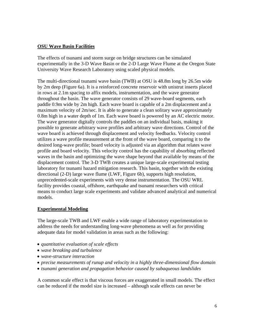
OSU Wave Basin Facilities The effects of tsunami and storm surge on bridge structures can be simulated experimentally in the 3-D Wave Basin or the 2-D Large Wave Flume at the Oregon State University Wave Research Laboratory using scaled physical models. The multi-directional tsunami wave basin (TWB) at OSU is 48.8m long by 26.5m wide by 2m deep (Figure 6a). It is a reinforced concrete reservoir with unistrut inserts placed in rows at 2.1m spacing to affix models, instrumentation, and the wave generator throughout the basin. The wave generator consists of 29 wave-board segments, each paddle 0.9m wide by 2m high. Each wave board is capable of a 2m displacement and a maximum velocity of 2m/sec. It is able to generate a clean solitary wave approximately 0.8m high in a water depth of 1m. Each wave board is powered by an AC electric motor. The wave generator digitally controls the paddles on an individual basis, making it possible to generate arbitrary wave profiles and arbitrary wave directions. Control of the wave board is achieved through displacement and velocity feedbacks. Velocity control utilizes a wave profile measurement at the front of the wave board, comparing it to the desired long-wave profile; board velocity is adjusted via an algorithm that relates wave profile and board velocity. This velocity control has the capability of absorbing reflected waves in the basin and optimizing the wave shape beyond that available by means of the displacement control. The 3-D TWB creates a unique large-scale experimental testing laboratory for tsunami hazard mitigation research. This basin, together with the existing directional (2-D) large wave flume (LWF, Figure 6b), supports high resolution, unprecedented-scale experiments with very dense instrumentation. The OSU WRL facility provides coastal, offshore, earthquake and tsunami researchers with critical means to conduct large scale experiments and validate advanced analytical and numerical models. Experimental Modeling The large-scale TWB and LWF enable a wide range of laboratory experimentation to address the needs for understanding long-wave phenomena as well as for providing adequate data for model validation in areas such as the following: • quantitative evaluation of scale effects • wave breaking and turbulence • wave-structure interaction • precise measurements of runup and velocity in a highly three-dimensional flow domain • tsunami generation and propagation behavior caused by subaqueous landslides A common scale effect is that viscous forces are exaggerated in small models. The effect can be reduced if the model size is increased – although scale effects can never be

7
entirely eliminated – hence a proper scale-effect evaluation is essential for laboratory experiments. Scale effects can be evaluated quantitatively by comparing identical experiments but using a wide range of model scales. Such investigations require a facility like the TWB, equipped with a precision wave generator and precise basin bathymetry. For example, if the scaling hypothesis is to be examined with runup motion onto a plane beach in a variety of scales, wave profiles and velocities must be measured at the same scaled positions relative to the beach toe. Dimensionless profiles and velocities should be identical at the same relative position in the absence of scale effects. Because the distance between the wave generator and the beach toe is physically fixed, the generated wave must be stable to provide identically scaled incident waves. This experiment therefore requires that the wave basin be sufficiently large to cover a wide range of scales, the basin floor be carefully constructed, and the wavemaker system be capable of generating a clean, stable wave such as solitary or cnoidal waves in a variety of water depths. Another critical research area is the investigation of wave forces on structures, especially forces associated with breaking and broken waves. Impact wave loads on a structure are affected by the scale effect due to viscous and surface tension forces associated with entrapped air-bubbles. Experiments at scales realizable in small laboratory basins produce exaggerated bubble sizes that are almost of the same order of magnitude as that of the impacted body. Because of the size of the TWB, it is capable of testing detailed models for more accurate measurements and representation of the fluid dynamics.
Numerical Modeling Two- and three-dimensional numerical models are being developed to identify regions along coastlines where long waves such as those generated by tsunami and storm surge can cause damage due to runup and overland flow. Such models are computationally complex and must incorporate movable and deformable surface piercing objects (e.g., Lynett, et al. 2000). The accurate numerical simulation of fluid-structure interaction such as those of tsunami and storm surge wave forces on bridge structures is a very challenging problem since the study of coastal waves and bridge structures have traditionally belonged to two different disciplines, namely, environmental hydrodynamics and structural mechanics/bridge engineering. While the modeling of bridge structures has been studied with success in the past, coupled wave-structure interaction is limited to special cases, mostly naval applications, with often highly simplified assumptions. While the research on each individual discipline is vast, the following sections briefly summarize the research on coastal waves and structures pertinent to this discussion. Wave Model -- To model a tsunami or storm surge approaching a beach as well as over land, the wave may be assumed to be breaking and/or broken. In this case, the research work of Liu’s group at Cornell University using the Reynolds Averaged Navier-Stokes (RANS) equation is most applicable (Lin and Liu 1998). They incorporated the k-ε
8
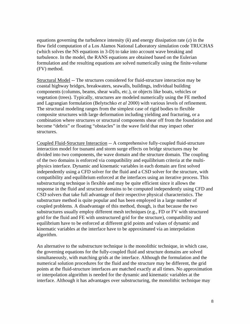
equations governing the turbulence intensity (k) and energy dissipation rate (ε) in the flow field computation of a Los Alamos National Laboratory simulation code TRUCHAS (which solves the NS equations in 3-D) to take into account wave breaking and turbulence. In the model, the RANS equations are obtained based on the Eulerian formulation and the resulting equations are solved numerically using the finite-volume (FV) method. Structural Model -- The structures considered for fluid-structure interaction may be coastal highway bridges, breakwaters, seawalls, buildings, individual building components (columns, beams, shear walls, etc.), or objects like boats, vehicles or vegetation (trees). Typically, structures are modeled numerically using the FE method and Lagrangian formulation (Belytschko et al 2000) with various levels of refinement. The structural modeling ranges from the simplest case of rigid bodies to flexible composite structures with large deformation including yielding and fracturing, or a combination where structures or structural components shear off from the foundation and become “debris” or floating “obstacles” in the wave field that may impact other structures. Coupled Fluid-Structure Interaction -- A comprehensive fully-coupled fluid-structure interaction model for tsunami and storm surge effects on bridge structures may be divided into two components, the wave domain and the structure domain. The coupling of the two domains is enforced via compatibility and equilibrium criteria at the multi-physics interface. Dynamic and kinematic variables in each domain are first solved independently using a CFD solver for the fluid and a CSD solver for the structure, with compatibility and equilibrium enforced at the interfaces using an iterative process. This substructuring technique is flexible and may be quite efficient since it allows the response in the fluid and structure domains to be computed independently using CFD and CSD solvers that take full advantage of their respective physical characteristics. The substructure method is quite popular and has been employed in a large number of coupled problems. A disadvantage of this method, though, is that because the two substructures usually employ different mesh techniques (e.g., FD or FV with structured grid for the fluid and FE with unstructured grid for the structure), compatibility and equilibrium have to be enforced at different grid points and values of dynamic and kinematic variables at the interface have to be approximated via an interpolation algorithm. An alternative to the substructure technique is the monolithic technique, in which case, the governing equations for the fully-coupled fluid and structure domains are solved simultaneously, with matching grids at the interface. Although the formulation and the numerical solution procedures for the fluid and the structure may be different, the grid points at the fluid-structure interfaces are matched exactly at all times. No approximation or interpolation algorithm is needed for the dynamic and kinematic variables at the interface. Although it has advantages over substructuring, the monolithic technique may
9
require more computational effort and increased memory due to the large number of coupled equations, and it is often prone to ill-conditioning. Recent Developments Since the inception of the TWB construction project, researchers at OSU have been developing computational fluid-structure interaction software and monitoring state-of-the-art developments in CFD and CSD in an effort to develop software that would be suitable for use by tsunami, storm surge and structural engineers. Selected developments related to the goals of this paper are presented here. Fully-Coupled CFD-CSD Software -- An NSF supported “pre-NEES” research project involving the development of 2-D fully coupled fluid-structure interaction simulation software, SFXC, to predict submarine landslide generated waves and fluid-structure interaction under waves is being conducted at OSU. This code extended the Cornell 2-D COBRAS finite difference, structured grid model (Lin and Liu 1998) by adding the capabilities of prescribed rigid boundary movements and fully coupled fluid-rigid structure interaction. Details of this research can be found in Yuk, et al. 2005. Latest Development in Particle FE Method -- In the study of tsunami and storm surge wave effects on bridge structures including TWB experiments, a unified approximation procedure covering both the fluid and structural domains with an exact representation of the fluid-structure interface is essential. The exact representation of the interface is necessary because the kinetic energy of the entire fluid-structure system is generated by the wave maker and dissipated by the bottom boundaries and moving structures. The dynamic response of the structure is governed by the equilibrium and compatibility constraints at the fluid-structure interface (as mentioned earlier, moving structures are also “wave makers”). “Exact” modeling of the fluid-structure interfaces is needed to achieve numerical accuracy and to ensure energy is dissipated properly during a simulation. Recently a finite-element based formulation of the fluid domain, called the particle finite element method (PFEM), has shown promising signs for unifying the simulation of fully-coupled fluid-structure interaction (Onate et al 2004). In this method, the continuity and momentum balance equations in the fluid domain are modeled using the Lagrangian formulation and discretized using the PFEM (Del Pin 2003). The boundaries at the free surface and at the interface between the fluid and the structure can be modeled exactly with a moving FE grid that is remeshed at every time step with the computationally efficient Delaunay tessellation technique. Commercial Software Applications -- A number of commercial simulation software packages including ANSYS, Star-CD/COMET and LS-DYNA to determine their TWB experiment modeling capabilities have been examined. The study revealed that LS-
10
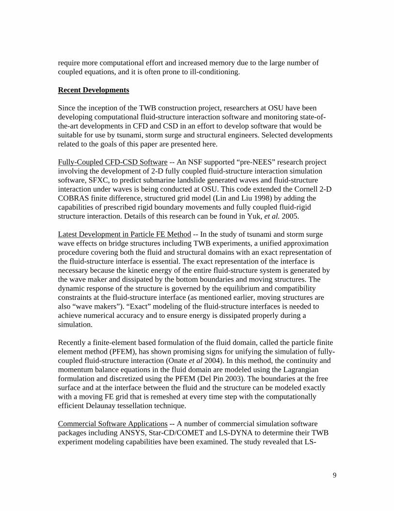
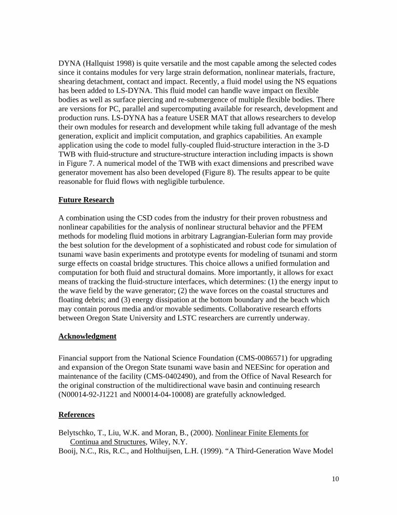
DYNA (Hallquist 1998) is quite versatile and the most capable among the selected codes since it contains modules for very large strain deformation, nonlinear materials, fracture, shearing detachment, contact and impact. Recently, a fluid model using the NS equations has been added to LS-DYNA. This fluid model can handle wave impact on flexible bodies as well as surface piercing and re-submergence of multiple flexible bodies. There are versions for PC, parallel and supercomputing available for research, development and production runs. LS-DYNA has a feature USER MAT that allows researchers to develop their own modules for research and development while taking full advantage of the mesh generation, explicit and implicit computation, and graphics capabilities. An example application using the code to model fully-coupled fluid-structure interaction in the 3-D TWB with fluid-structure and structure-structure interaction including impacts is shown in Figure 7. A numerical model of the TWB with exact dimensions and prescribed wave generator movement has also been developed (Figure 8). The results appear to be quite reasonable for fluid flows with negligible turbulence. Future Research A combination using the CSD codes from the industry for their proven robustness and nonlinear capabilities for the analysis of nonlinear structural behavior and the PFEM methods for modeling fluid motions in arbitrary Lagrangian-Eulerian form may provide the best solution for the development of a sophisticated and robust code for simulation of tsunami wave basin experiments and prototype events for modeling of tsunami and storm surge effects on coastal bridge structures. This choice allows a unified formulation and computation for both fluid and structural domains. More importantly, it allows for exact means of tracking the fluid-structure interfaces, which determines: (1) the energy input to the wave field by the wave generator; (2) the wave forces on the coastal structures and floating debris; and (3) energy dissipation at the bottom boundary and the beach which may contain porous media and/or movable sediments. Collaborative research efforts between Oregon State University and LSTC researchers are currently underway. Acknowledgment Financial support from the National Science Foundation (CMS-0086571) for upgrading and expansion of the Oregon State tsunami wave basin and NEESinc for operation and maintenance of the facility (CMS-0402490), and from the Office of Naval Research for the original construction of the multidirectional wave basin and continuing research (N00014-92-J1221 and N00014-04-10008) are gratefully acknowledged. References Belytschko, T., Liu, W.K. and Moran, B., (2000). Nonlinear Finite Elements for
Continua and Structures, Wiley, N.Y. Booij, N.C., Ris, R.C., and Holthuijsen, L.H. (1999). “A Third-Generation Wave Model

11
for Coastal Regions, Part I, Model Description and Validation,” Geophysical Research, 104(C4), pp.7649-7666
Cheung, K.F., Phadke, A.C., Wei, Y., Rojas, R., Douyere, Y.J.M., Martino, C.D., Houston, S.H., Liu, P.L.F., Lynette, P.J., Dodd, N., Liao, S., and Nakazaki, E. (2003). “Modeling of Storm-Induced Coastal Floding for Emergency Management,” Ocean Engineering, Vol. 30, pp.1353-1386.
Del Pin, F., (2003). “The Meshless Finite Element Method Applied to a Lagrangian Formulation of Fluid Flows,” Ph.D. Thesis, Universidad Nacional del Litoral.
Geist, E.L. (1999). “Modeling the Natural Complexities of a Local Tsunami,” International Tsunami Society Proceedings, Session 7, No. 7-5, pp.751-758.
Hallquist, J.O., (1998). “LS-DYNA Theoretical Manual,” Livermore Software Technology Corporation.
Headland, J. (2005). American Society of Civil Engineers Indian Ocean Tsunami Survey Report (http://www.asce.org/page/?id=57; http://www.coprinstitute.org/enews/spirng05/tsunami.html)
Jelesnianski, C.P., Chen, J., and Shaffer, W.A. (1992). “SLOSH: Sea, Land and Overland Surges from Hurricanes,” NOAA Technical Report, NWS 48, Silver Springs, Maryland.
Komen, G.J., Cavaleri, L., Donelan, M., Hasselmann, K., Hasselmann, S., and Janssen, P.A.E.M. (1994). Dynamics and Modeling of Ocean Waves, Cambridge University Press, Cambridge.
Mastenbroek, C., Burgers, G., and Janssen, P.A.E.M. (1993). “The Dynamical Coupling of a Wave Model and a Storm Surge Model through the Atmospheric Boundary Layer,” Physical Oceanography, Vol. 23(8), pp.1271-1285.
Lin, P. and Liu, P.L-F., 1998. “A Numerical Study of Breaking Waves in the Surf Zone,” Fluid Mechanics, Vol.359, pp.239-264.
Lynett, P. J., Liu, P. L.-F., Losada, I. J. and Vidal, C. (2000) “Solitary Wave Interaction with Porous Breakwater”, Waterway, Port, Coastal and Ocean Engrg., ASCE, Vol.126, pp. 314-322.
Lynett, P. J., Wu, T.R. and Liu, P.L-F., (2002). “Modeling Wave Runup with Depth-Integrated Equations,” Coastal Engineering, Vol.46(2), pp.89-108.
Onate, E., Idelsohn, S.R., Del Pin, F. and Aubry, R. 2004. “The Particle Finite Element Method – An Overview,” International Journal of Computational Methods, Vol.1, No.2, 2004, pp.267-307.
Yeh, H. (2003). “Tsunami Scour Around a Cylinder,” Fluid Mechanics, Vol.496, pp.165-192.
Yeh, H. and Robertson, I. (2005). “Development of Design Guideline for Tsunami Shelters,” First International Conference on Urban Disaster Reduction, Jan. 18-20, 2005, Kobe, Japan.
Yuk, D., Yim, S.C. and Liu, P.L-F., “Numerical Modeling of Submarine Mass-Movement Generated Waves Using RANS Model,” Computers and Geosciences, in press, 2005.

12
Figure 1a. Original Coastline and Bridge Structures, Banda Aceh, Indonesia, before Dec. 2004.
Figure 2a. Overview of original Bridge structures at Biloxi, MS, before Sept. 2005.
Figure 3a. Damaged Concrete Bridge, Banda Aceh, Indonesia, Dec. 2004.
Figure 1b. Damaged Coastline and Bridge Structures, Banda Aceh, Indonesia, after Dec. 2004.
Figure 2b. Overview of damaged Bridge structures at Biloxi, MS, after Sept. 2005.
Figure 3b. Damaged Concrete Bridge near New Orleans, LA Sept. 2005.

13
Figure 4a. Supporting piers of Arugam Bridge in Sri Lanka shifted due to foundation Scour in the Dec. 2004 Indian Ocean Tsunami.
Figure 5a. Barge as floating debris in Banda Aceh, Indonesia during the Dec. 2004 Indian Ocean Tsunami.
Figure 6a. The NEES 3-D Wave Basin at Oregon State University.
Figure 4b. Collapse of pedestal of the Karaikal Bridge in India due to scour in the Dec. 2004 Indian Ocean Tsunami.
Figure 5b. Oil drilling rig broken loose and hitting the Cochrane-Africatown bridge across the Mobile River in AL during the Sept. 2005 Katrina Hurricane and Storm Surge.
Figure 6b. The NEES 2-D Large Wave Flume at Oregon State University.
14
Figure 7. Fluid-Structure Interaction with Fluid-Structure-Structure Impact.
Figure 8. Simulation of NEES TWB’s 29–paddle wavemaker generating directional wave.