Embed Size (px)
Citation preview
Gazi Mühendislik Bilimleri Dergisi 2019, 5(1): 91-100
Araştırma Makalesi/Research Article gmbd.gazipublishing.com
Modeling and Simulation of DC Motor Using Simelectronics and
Simulink
Ayodeji OKUBANJO*,a
, Oluwadamilola OYETOLA a, Olawale OLALUWOYE
a , Olufemi
ALAO a, Adeyemi OLATEJU
b, Taiwo ABATAN
b
a,* Olabisi Onabanjo University, Department of Electrical Electronics Engineering, PMB 2002, Ago Iwoye, NIGERIA b Moshood Abiola Polytechnic, Department of Computer Engineering, Ogun State, NIGERIA
ARTICLE
INFO
ÖZET
Received: 14.02.2019
Accepted: 20.04.2019
This paper describes the development of mathematical and physical Modeling based simulators in
the Simulink © Simscape TM environment as interactive tools to demonstrate the DC motor
responses in terms of current, speed and torque. This type of Modeling requires to join the physical
components with physical connections to define the underlying dynamic equations of the DC
motor. This approach is further compared with the analytical model in Simulink. To support our
proposal, numerical simulations and mathematical Modeling of the DC motor are derived using the
Lagrangian and Euler-Lagrange approach contrary to the existing Kirchhoff’s’ and Newton laws.
The state space model is formulated based on Hamilton’s equation. The simulation models are
developed as part of software laboratory support and to enhance undergraduate control systems
and machinery courses at Olabisi Onabanjo UniversityA proportional Derivative (PD) controller is
implemented for both the models to compensate for fast response in the armature current and
electromagnetic torque. A comparative study of the model for the separately excited Dc motor has
shown that the models have their own merits and demerits.
https://dx.doi.org/10.30855/gmbd.2019.01.09
Keywords: Direct Current Motor,
Soimulink and Simelectronics,
Hamilton Equation,
Euler-Lagrange, PD
Corresponding
Authors okubanjo.ayodeji@oo
uagoiwoye.edu.ng
1. INTRODUCTION (GİRİŞ) To stimulate students’ interest in practical engineering
based degree and also to bridge the gap between the
practical and theoretical skills, the use of computer -
based software tools has been integrated into the field of
Engineering. Presently, educators and researchers
developed a huge variety of resources to enhance the
teaching of Engineering based Laboratory courses. In
the Mechatronic and Control field, there are a
considerable number of specialized and general purpose
Virtual Laboratory tools available for experimental
purpose. MATLAB® / Simulink© is introduced to the
Engineering curriculum due to their extended use for
both design and the simulation of the control system.
Furthermore, the potential of Simulink© has been
extended by adding a multitude of toolboxes, among
which are interested in emphasizing Simscape TM
for
physical modeling. It is an object-oriented enriched
environment which joins the physical components with
physical connections to define the underlying dynamic
equation of the system. Unlike other Simulink blocks,
Simscape directly represents physical elements or
relation. Hence, a system model can be built in this
environment in a similar way that a physical system is
assembled. Therefore, Simscape as a Virtual Laboratory
tool enhances students’ motivation to learn and simulate
dynamic of the complex system in an interactive mode.
In recent times, DC motors have been proven as core
ingredient in speed control and it is gaining a limelight
with integration of renewable energy for most
automobiles and mechatronics applications. It is widely
used as energy conversion devices[1], serves as a speed
drive control in electric cars and electric traction[2], [3],
as an actuators in robotic manipulators [4], [5] and
smart wheelchair[6], used in overhead cranes, medical
treatment, power electronics dc drive applications [7]–
[9]. Recently, the demand for DC motors in speed
control for hybrid vehicles powered with internal
combustion and electric engines is steadily increasing
with the attention to reduce fossil-fuel based vehicles
and to mitigate the global warming gas emissions. The
existing works[10]–[12] have been limited to
formulation of mathematical model using Kirchhoff’s
law and Newton’s law of motion which is further
Okubanjo, Oyetola, Olaluwoye, Alao, Olateju, Abatan / Gazi Mühendislik Bilimleri Dergisi 5 (1). (2019) 91-100
PRINT ISSN: 2149-4916 E-ISSN: 2149-9373 © 2017 Gazi Akademik Yayıncılık
92
converted to frequency domain-Laplace transform to
obtain the system transfer function. However, this paper
proposed a novel Lagrangian and Euler-Lagrange
coupled with Hamilton’s approaches to formulate the
mathematical models and developed two different
simulation models to simulate the system dynamic of
the DC motor accurately and emphasis the usefulness of
such approaches in the field of electrical engineering to
support teaching in automatic control. The general
configuration, dynamic equation, analysis, characteristic
and control of DC motor are presented in Nise[13].
Pal[14] proposed a generalized dynamic modeling of
DC motor based on state space approach. In Khanna[15]
presented a model predictive control model for a DC
motor. Some models and simulation software based
related to DC motor are presented in [16]–[18] and
Gencer[19] further extended model to brushless DC
motor in Simulink. Chen[11] further introduced a
Simulink based model. Venu[20] proposed a PID
controller algorithm for DC motor control in state space
domain. A performance comparative analysis of PI
controller and Artificial Intelligent control is
investigated in Abdulrahman[21], [22]. Jafar et al [23]
proposed an improve rotor speed of a brushless Dc
motor using fuzzy controller. In [24] a proportional-
integral (PI) controller is implemented to improve the
battery performance of electric motor vehicle. A java
web-application software is developed for a DC motor
position control in[25] . Similarly, a virtual electrical
machine laboratory tool for Dc the motor is developed
to enhance practical electronic learning of DC moor
dynamic and responses [26], [27]. The main objective of
this paper is to show the advantages of using physical
modeling to develop interactive resources to support
teaching and learning in Automatic Control. Thus, the
idea is to build a simulator for laboratory courses with
which the students can validate their designed controller
so as to provide an alternative to the use of real platform
that needs a heavy budget in terms of resources.
2. MATERIAL AND METHODS (MALZEME VE
YÖNTEMLER)
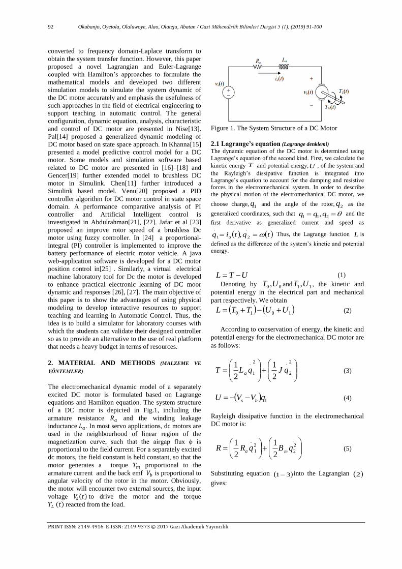
The electromechanical dynamic model of a separately
excited DC motor is formulated based on Lagrange
equations and Hamilton equation. The system structure
of a DC motor is depicted in Fig.1, including the
armature resistance 𝑅𝑎 and the winding leakage
inductance 𝐿𝑎. In most servo applications, dc motors are
used in the neighbourhood of linear region of the
magnetization curve, such that the airgap flux ϕ is
proportional to the field current. For a separately excited
dc motors, the field constant is held constant, so that the
motor generates a torque 𝑇𝑚 proportional to the
armature current and the back emf 𝑉𝑏 is proportional to
angular velocity of the rotor in the motor. Obviously,
the motor will encounter two external sources, the input
voltage 𝑉𝑠(𝑡) to drive the motor and the torque
𝑇𝐿 (𝑡) reacted from the load.
Figure 1. The System Structure of a DC Motor
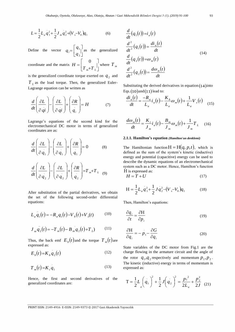
2.1 Lagrange’s equation (Lagrange denklemi) The dynamic equation of the DC motor is determined using
Lagrange’s equation of the second kind. First, we calculate the
kinetic energy T and potential energy,U , of the system and
the Rayleigh’s dissipative function is integrated into
Lagrange’s equation to account for the damping and resistive
forces in the electromechanical system. In order to describe
the physical motion of the electromechanical DC motor, we
choose charge, 1q and the angle of the rotor, 2q as the
generalized coordinates, such that 211 ,qqq and the
first derivative as generalized current and speed as
tqtiq a .
21
.
, Thus, the Lagrange function L is
defined as the difference of the system’s kinetic and potential
energy.
UTL (1)
Denoting by 00 ,UT and 11 ,UT , the kinetic and
potential energy in the electrical part and mechanical
part respectively. We obtain
1010 UUTTL (2)
According to conservation of energy, the kinetic and
potential energy for the electromechanical DC motor are
as follows:
2
2
.2
1
.
2
1
2
1qJqLT a (3)
1qVVU bs (4)
Rayleigh dissipative function in the electromechanical
DC motor is:
.2
2
2
1
.
2
1
2
1qBqRR
ma (5)
Substituting equation 31 into the Lagrangian 2
gives:
Okubanjo, Oyetola, Olaluwoye, Alao, Olateju, Abatan / Gazi Mühendislik Bilimleri Dergisi 5 (1). (2019) 91-100
PRINT ISSN: 2149-4916 E-ISSN: 2149-9373 © 2017 Gazi Akademik Yayıncılık
93
1
2
2
.2
1
.
2
1
2
1qVVqJqLL bsma
(6)
Define the vector
2
1
q
qq i
as the generalized
coordinate and the matrix
Lm TTH
0where mT
is the generalized coordinate torque exerted on 2q and
LT as the load torque. Then, the generalized Euler-
Lagrange equation can be written as
H
q
R
qi
L
qi
L
dt
d
i
...
(7)
Lagrange’s equations of the second kind for the
electromechanical DC motor in terms of generalized
coordinates are as:
0.
1
.
1
.
1
q
R
q
L
q
L
dt
d (8)
Lm TT
q
R
q
L
q
L
dt
d
.
2
.
2
.
2
(9)
After substitution of the partial derivatives, we obtain
the set of the following second-order differential
equations:
)(11
..
tVtVtqRtqL sbaa (10)
)2
...
2 LmmmTtqBtTtqJ (11)
Thus, the back emf tE b and the torque tT m are
expressed as:
tqKtEbb 2
.
(12)
1
.
qKtTtm (13)
Hence, the first and second derivatives of the
generalized coordinates are:
dt
tdtq
dt
d
ttqdt
d
dt
tditq
dt
d
titqdt
d
m
m
a
a
22
2
2
12
2
1
(14)
Substituting the derived derivatives in equation 14 into
Eqs. 10 and 11 lead to:
tV
Lt
L
Kti
L
R
dt
tdis
a
m
a
b
a
a
aa 1
(15)
L
m
m
m
m
a
m
tm TJ
tJ
Bti
J
K
dt
td 1
(16)
2.1.1. Hamilton’s equation (Hamilton'un denklemi)
The Hamiltonian function tpq ,, , which is
defined as the sum of the system’s kinetic (inductive)
energy and potential (capacitive) energy can be used to
describe the dynamic equations of an electromechanical
system such as a DC motor. Hence, Hamilton’s function
is expressed as:
UTH (17)
1
2
2
.2
1
.
2
1
2
1qVVqJqL bsa
(18)
Then, Hamilton’s equations:
i
i
pt
q
(19)
ii q
Gp
q
.
1 (20)
State variables of the DC motor from Fig.1 are the
charge flowing in the armature circuit and the angle of
the rotor 21,qq respectively and momentum 21,pp .
The kinetic (inductive) energy in terms of momentum is
expressed as:
J
p
L
pqJqL
aa 222
1
2
12
2
21
2.
2
2.
1
(21)
Okubanjo, Oyetola, Olaluwoye, Alao, Olateju, Abatan / Gazi Mühendislik Bilimleri Dergisi 5 (1). (2019) 91-100
PRINT ISSN: 2149-4916 E-ISSN: 2149-9373 © 2017 Gazi Akademik Yayıncılık
94
Potential (capacitive) energy
ibs qVVU (22)
Rayleigh’s dissipative function or content of the system
2,1,2
1
2
1 2.
2.
iqBqRG iimia (23)
Generalized linear force for viscous (resistive) damping
is expressed as the content of the system function as:
2,1,
i
q
GQ
i
i (24)
Generalized forces
tTtTQQ Lmee 21
,0 (25)
Dynamic equation of the electromechanical DC motor
are obtain in the form:
dt
tdqq
q
11
.
1
(26)
dt
tdqq
q
22
.
2
(27)
11
1
1eQQ
qdt
tdp
(28)
22
2
2eQQ
qdt
tdp
(29)
So that,
aL
tp
dt
tdq 11 (30)
11
.1 p
L
RVVqRVV
dt
tdp
a
a
bsabs
(10
)
J
tp
dt
tdq 22 (31)
tTtTtqB
dt
tdpLmm
.
22
(32)
In matrix form:
tT
tB
tp
tq
tp
tq
A
dt
tdpdt
tdqdt
tdpdt
tdq
L
s
2
2
1
1
2
2
1
1
V.. (33)
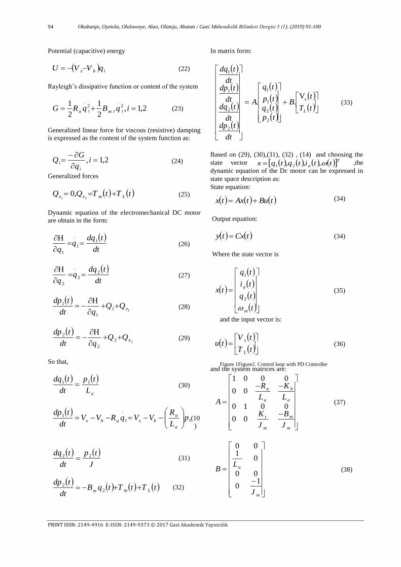
Based on (29), (30),(31), (32) , (14) and choosing the
state vector Ta ttitqtqx ,,, 21 ,the
dynamic equation of the Dc motor can be expressed in
state space description as:
State equation:
tButAxtx .
(34)
Output equation:
tCxty (34)
Where the state vector is
t
tq
ti
tq
tx
m
a
2
1
(35)
and the input vector is:
tT
tVtu
L
s (36)
and the system matrices are:
m
m
m
t
a
b
a
a
J
B
J
K
L
K
L
R
A
00
0010
00
0001
(37)
m
a
J
LB
10
00
01
00
(38)
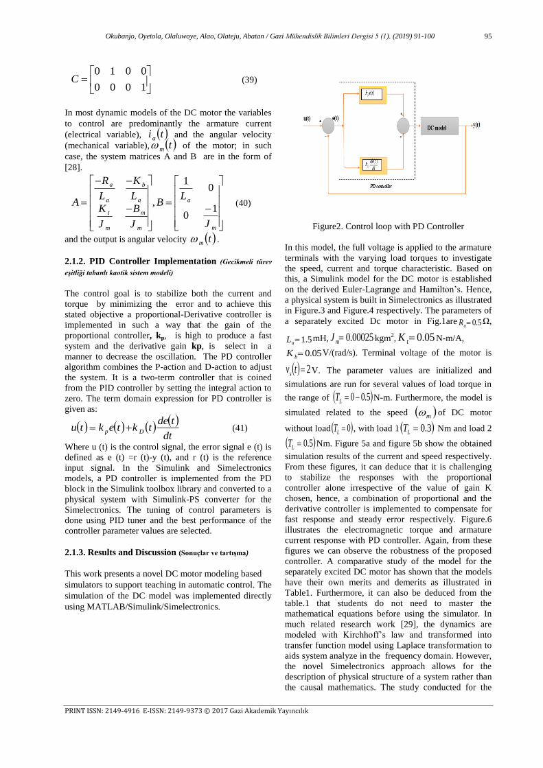
Figure 1Figure2. Control loop with PD Controller
Okubanjo, Oyetola, Olaluwoye, Alao, Olateju, Abatan / Gazi Mühendislik Bilimleri Dergisi 5 (1). (2019) 91-100
PRINT ISSN: 2149-4916 E-ISSN: 2149-9373 © 2017 Gazi Akademik Yayıncılık
95
1000
0010C (39)
In most dynamic models of the DC motor the variables
to control are predominantly the armature current
(electrical variable), ti a and the angular velocity
(mechanical variable), tm of the motor; in such
case, the system matrices A and B are in the form of
[28].
m
a
m
m
m
t
a
b
a
a
J
LB
J
B
J
K
L
K
L
R
A1
0
01
, (40)
and the output is angular velocity tm .
2.1.2. PID Controller Implementation (Gecikmeli türev
eşitliği tabanlı kaotik sistem modeli)
The control goal is to stabilize both the current and
torque by minimizing the error and to achieve this
stated objective a proportional-Derivative controller is
implemented in such a way that the gain of the
proportional controller, kp, is high to produce a fast
system and the derivative gain kp, is select in a
manner to decrease the oscillation. The PD controller
algorithm combines the P-action and D-action to adjust
the system. It is a two-term controller that is coined
from the PID controller by setting the integral action to
zero. The term domain expression for PD controller is
given as:
dt
tdetktektu Dp (41)
Where u (t) is the control signal, the error signal e (t) is
defined as e (t) =r (t)-y (t), and r (t) is the reference
input signal. In the Simulink and Simelectronics
models, a PD controller is implemented from the PD
block in the Simulink toolbox library and converted to a
physical system with Simulink-PS converter for the
Simelectronics. The tuning of control parameters is
done using PID tuner and the best performance of the
controller parameter values are selected.
2.1.3. Results and Discussion (Sonuçlar ve tartışma)
This work presents a novel DC motor modeling based
simulators to support teaching in automatic control. The
simulation of the DC model was implemented directly
using MATLAB/Simulink/Simelectronics.
Figure2. Control loop with PD Controller
In this model, the full voltage is applied to the armature
terminals with the varying load torques to investigate
the speed, current and torque characteristic. Based on
this, a Simulink model for the DC motor is established
on the derived Euler-Lagrange and Hamilton’s. Hence,
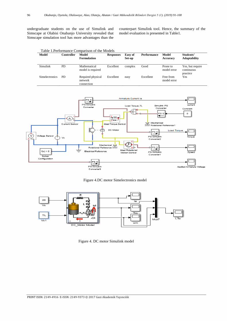
a physical system is built in Simelectronics as illustrated
in Figure.3 and Figure.4 respectively. The parameters of
a separately excited Dc motor in Fig.1are 5.0aR Ω,
5.1aL mH, 00025.0mJ kgm2, 05.0tK N-m/A,
05.0bK V/(rad/s). Terminal voltage of the motor is
2tvs V. The parameter values are initialized and
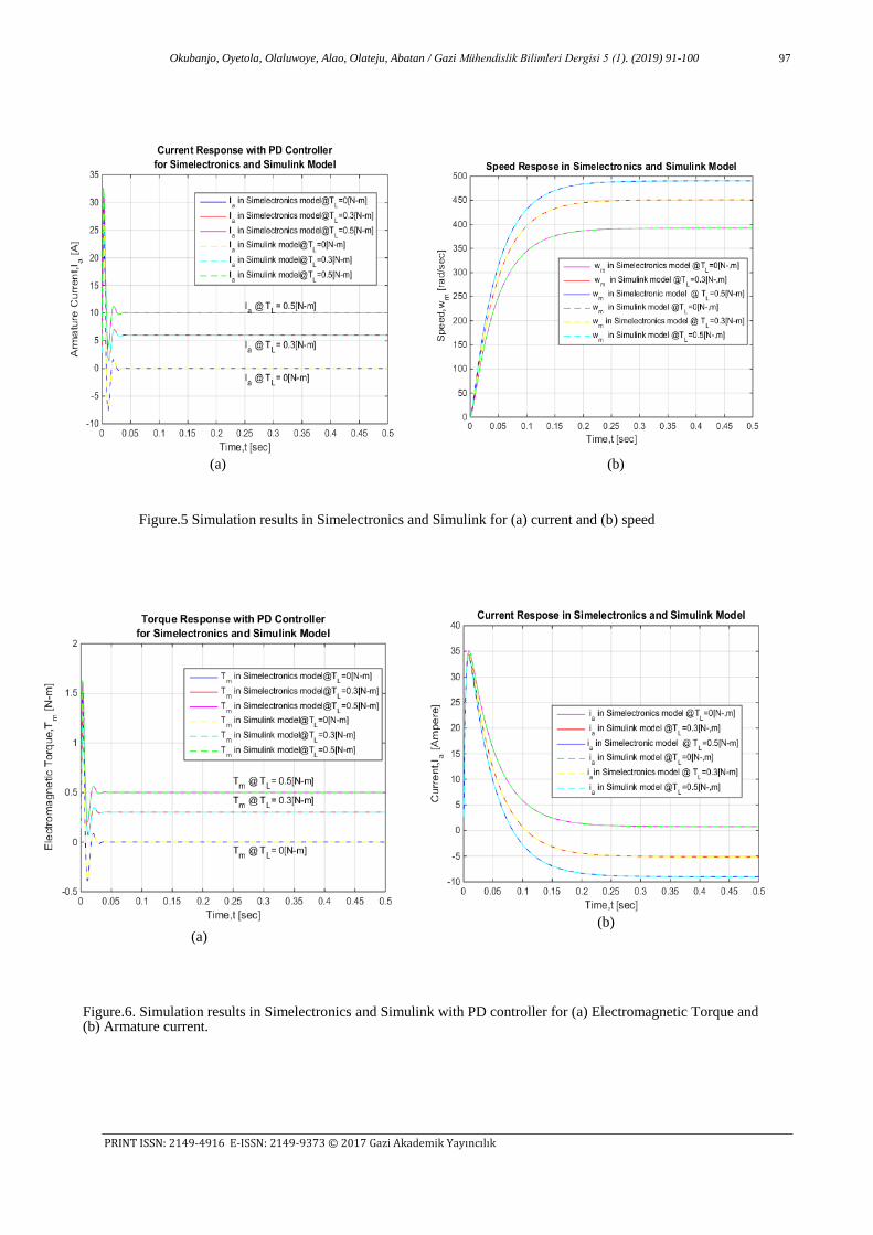
simulations are run for several values of load torque in
the range of 5.00LT N-m. Furthermore, the model is
simulated related to the speed m of DC motor
without load 0LT , with load 1 3.0LT Nm and load 2
5.0LT Nm. Figure 5a and figure 5b show the obtained
simulation results of the current and speed respectively.
From these figures, it can deduce that it is challenging
to stabilize the responses with the proportional
controller alone irrespective of the value of gain K
chosen, hence, a combination of proportional and the
derivative controller is implemented to compensate for
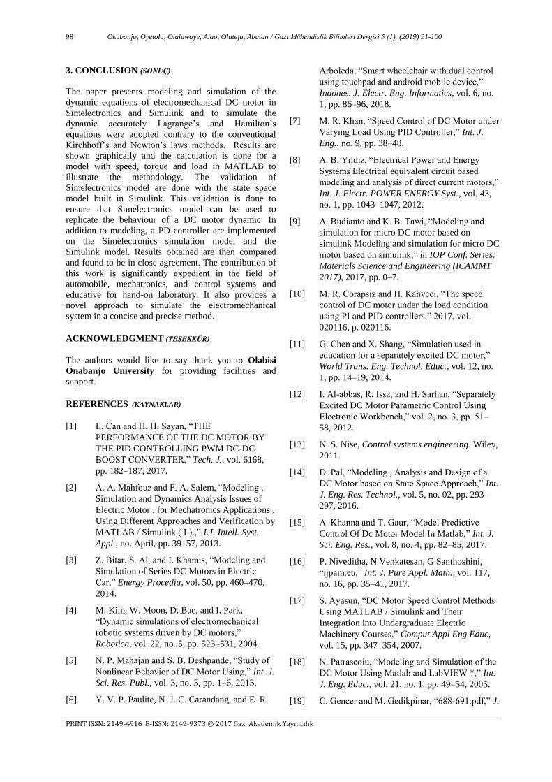
fast response and steady error respectively. Figure.6
illustrates the electromagnetic torque and armature
current response with PD controller. Again, from these
figures we can observe the robustness of the proposed
controller. A comparative study of the model for the
separately excited DC motor has shown that the models
have their own merits and demerits as illustrated in
Table1. Furthermore, it can also be deduced from the
table.1 that students do not need to master the
mathematical equations before using the simulator. In
much related research work [29], the dynamics are
modeled with Kirchhoff’s law and transformed into
transfer function model using Laplace transformation to
aids system analyze in the frequency domain. However,
the novel Simelectronics approach allows for the
description of physical structure of a system rather than
the causal mathematics. The study conducted for the
Okubanjo, Oyetola, Olaluwoye, Alao, Olateju, Abatan / Gazi Mühendislik Bilimleri Dergisi 5 (1). (2019) 91-100
PRINT ISSN: 2149-4916 E-ISSN: 2149-9373 © 2017 Gazi Akademik Yayıncılık
96
undergraduate students on the use of Simulink and
Simscape at Olabisi Onabanjo University revealed that
Simscape simulation tool has more advantages than the
counterpart Simulink tool. Hence, the summary of the
model evaluation is presented in Table1.
Table 1.Performance Comparison of the Models
Model Controller Model
Formulation
Responses Easy of
Set-up
Performance Model
Accuracy
Students’
Adaptability
Simulink PD Mathematical model is required
Excellent complex Good Prone to model error
Yes, but require continuous
practice
Simelectronics PD Required physical network
connection
Excellent easy Excellent Free from model error
Yes
Figure 4.DC motor Simelectronics model
Figure 4. DC motor Simulink model
Okubanjo, Oyetola, Olaluwoye, Alao, Olateju, Abatan / Gazi Mühendislik Bilimleri Dergisi 5 (1). (2019) 91-100
PRINT ISSN: 2149-4916 E-ISSN: 2149-9373 © 2017 Gazi Akademik Yayıncılık
97
(a)
(a)
(b)
(b)
(b)
(b)
(b)
Figure.5 Simulation results in Simelectronics and Simulink for (a) current and (b) speed
Figure.6. Simulation results in Simelectronics and Simulink with PD controller for (a) Electromagnetic Torque and (b) Armature current.
Okubanjo, Oyetola, Olaluwoye, Alao, Olateju, Abatan / Gazi Mühendislik Bilimleri Dergisi 5 (1). (2019) 91-100
PRINT ISSN: 2149-4916 E-ISSN: 2149-9373 © 2017 Gazi Akademik Yayıncılık
98
3. CONCLUSION (SONUÇ)
The paper presents modeling and simulation of the
dynamic equations of electromechanical DC motor in
Simelectronics and Simulink and to simulate the
dynamic accurately Lagrange’s and Hamilton’s
equations were adopted contrary to the conventional
Kirchhoff’s and Newton’s laws methods. Results are
shown graphically and the calculation is done for a
model with speed, torque and load in MATLAB to
illustrate the methodology. The validation of
Simelectronics model are done with the state space
model built in Simulink. This validation is done to
ensure that Simelectronics model can be used to
replicate the behaviour of a DC motor dynamic. In
addition to modeling, a PD controller are implemented
on the Simelectronics simulation model and the
Simulink model. Results obtained are then compared
and found to be in close agreement. The contribution of
this work is significantly expedient in the field of
automobile, mechatronics, and control systems and
educative for hand-on laboratory. It also provides a
novel approach to simulate the electromechanical
system in a concise and precise method.
ACKNOWLEDGMENT (TEŞEKKÜR)
The authors would like to say thank you to Olabisi
Onabanjo University for providing facilities and
support.
REFERENCES (KAYNAKLAR)
[1] E. Can and H. H. Sayan, “THE
PERFORMANCE OF THE DC MOTOR BY
THE PID CONTROLLING PWM DC-DC
BOOST CONVERTER,” Tech. J., vol. 6168,
pp. 182–187, 2017.
[2] A. A. Mahfouz and F. A. Salem, “Modeling ,
Simulation and Dynamics Analysis Issues of
Electric Motor , for Mechatronics Applications ,
Using Different Approaches and Verification by
MATLAB / Simulink ( I ).,” I.J. Intell. Syst.
Appl., no. April, pp. 39–57, 2013.
[3] Z. Bitar, S. Al, and I. Khamis, “Modeling and
Simulation of Series DC Motors in Electric
Car,” Energy Procedia, vol. 50, pp. 460–470,
2014.
[4] M. Kim, W. Moon, D. Bae, and I. Park,
“Dynamic simulations of electromechanical
robotic systems driven by DC motors,”
Robotica, vol. 22, no. 5, pp. 523–531, 2004.
[5] N. P. Mahajan and S. B. Deshpande, “Study of
Nonlinear Behavior of DC Motor Using,” Int. J.
Sci. Res. Publ., vol. 3, no. 3, pp. 1–6, 2013.
[6] Y. V. P. Paulite, N. J. C. Carandang, and E. R.
Arboleda, “Smart wheelchair with dual control
using touchpad and android mobile device,”
Indones. J. Electr. Eng. Informatics, vol. 6, no.
1, pp. 86–96, 2018.
[7] M. R. Khan, “Speed Control of DC Motor under
Varying Load Using PID Controller,” Int. J.
Eng., no. 9, pp. 38–48.
[8] A. B. Yildiz, “Electrical Power and Energy
Systems Electrical equivalent circuit based
modeling and analysis of direct current motors,”
Int. J. Electr. POWER ENERGY Syst., vol. 43,
no. 1, pp. 1043–1047, 2012.
[9] A. Budianto and K. B. Tawi, “Modeling and
simulation for micro DC motor based on
simulink Modeling and simulation for micro DC
motor based on simulink,” in IOP Conf. Series:
Materials Science and Engineering (ICAMMT
2017), 2017, pp. 0–7.
[10] M. R. Corapsiz and H. Kahveci, “The speed
control of DC motor under the load condition
using PI and PID controllers,” 2017, vol.
020116, p. 020116.
[11] G. Chen and X. Shang, “Simulation used in
education for a separately excited DC motor,”
World Trans. Eng. Technol. Educ., vol. 12, no.
1, pp. 14–19, 2014.
[12] I. Al-abbas, R. Issa, and H. Sarhan, “Separately
Excited DC Motor Parametric Control Using
Electronic Workbench,” vol. 2, no. 3, pp. 51–
58, 2012.
[13] N. S. Nise, Control systems engineering. Wiley,
2011.
[14] D. Pal, “Modeling , Analysis and Design of a
DC Motor based on State Space Approach,” Int.
J. Eng. Res. Technol., vol. 5, no. 02, pp. 293–
297, 2016.
[15] A. Khanna and T. Gaur, “Model Predictive
Control Of Dc Motor Model In Matlab,” Int. J.
Sci. Eng. Res., vol. 8, no. 4, pp. 82–85, 2017.
[16] P. Niveditha, N Venkatesan, G Santhoshini,
“ijpam.eu,” Int. J. Pure Appl. Math., vol. 117,
no. 16, pp. 35–41, 2017.
[17] S. Ayasun, “DC Motor Speed Control Methods
Using MATLAB / Simulink and Their
Integration into Undergraduate Electric
Machinery Courses,” Comput Appl Eng Educ,
vol. 15, pp. 347–354, 2007.
[18] N. Patrascoiu, “Modeling and Simulation of the
DC Motor Using Matlab and LabVIEW *,” Int.
J. Eng. Educ., vol. 21, no. 1, pp. 49–54, 2005.
[19] C. Gencer and M. Gedikpinar, “688-691.pdf,” J.
Okubanjo, Oyetola, Olaluwoye, Alao, Olateju, Abatan / Gazi Mühendislik Bilimleri Dergisi 5 (1). (2019) 91-100
PRINT ISSN: 2149-4916 E-ISSN: 2149-9373 © 2017 Gazi Akademik Yayıncılık
99
Appl. Sci., vol. 6, no. 3, pp. 688–691, 2006.
[20] K. V. C. R. V. Rajasekhar, “Design and
Analysis of DC Motor With PID Controller - A
State Space Approach,” ITSI Trans. Electr.
Electron. Eng., vol. 1, no. 3, pp. 11–14, 2013.
[21] A. A. A. Emhemed and R. Bin Mamat,
“Modelling and simulation for Industrial DC
Motor using Intelligent control,” in Procedia
Engineering, 2012, vol. 41, no. Iris, pp. 420–
425.
[22] C. Felipe and R. Rodas, “A performance
comparison of nonlinear and linear control for a
DC series motor Una comparación de
desempeño del control Lineal y no lineal de un
motor de corriente continua,” Cienc. en
Desarro., vol. 8, no. 1, pp. 41–50, 2017.
[23] J. Mostafapour, J. Reshadat, and M. Farsadi,
“Improved Rotor Speed Brushless DC Motor
Using Fuzzy Controller,” Indones. J. Electr.
Eng. Informatics, vol. 3, no. 2, pp. 78–88, 2015.
[24] N. K. Saxena, S. Gebrehiwot, and D. Mena,
“Controller Design for Electric Motor Derived
Vehicle,” Indones. J. Electr. Eng. Informatics,
vol. 6, no. 2, pp. 6–12, 2018.
[25] H. Wong and V. Kapila, “Internet-based remote
control of a DC motor using an embedded
ethernet microcontroller,” Comput. Educ. J.,
vol. 15, no. 3, pp. 57–67, 2005.
[26] M. F. Işik, “Design and implementation of a
training set for distributed system and
mechatronic applications: project based
learning,” Teh. Vjesn. - Tech. Gaz., vol. 23, no.
6, pp. 1609–1616, 2016.
[27] M. Işik F., M. & Güngör A., “AWERProcedia
Information Technology & Computer Science
Virtual Laboratory Application for Direct
Current Motor Experiments,” in AWERProcedia
Information Technology & Computer Science,
2016, no. February, pp. 552–57.
[28] A.A.Okubanjo and O.K.Oyetola, “Modeling and
Simulation of Hybrid PV- Thermal (PVT)
Systems for Energy Efficiency in Nigeria,”
Amity J. Eng. Technol. J. Eng. Technol., vol. 2,
no. 1, pp. 7–15, 2017.
[29] D. Puangdownreong, A. Nawikavatan, and C.
Thammarat, “Optimal Design of I-PD
Controller for DC Motor Speed Control System
by Cuckoo Search,” Procedia - Procedia
Comput. Sci., vol. 86, no. March, pp. 83–86,
2016.
Nomenclature Jm equivalent moment of inertial of motor and load
referred to motor shaft
Bm equivalent viscous friction coefficient of motor and
load referred to motor shaft
La inductance of armature winding
Ra resistance of the armature winding
Vb back emf (volts)
Tm Torque developed by the motor
TL load Torque (Nm)
ωm angular velocity of motor shaft
Kt, Kb motor torque constant and back emf constant
H Hamilton’s function
L Lagrange’s function
T kinetic energy
U potential energy
G, R Rayleigh’s dissipative function
pi momentum of the i-th numbe
Ayodeji OKUBANJO
A.A. Okubanjo received B.Sc. Degree in Electrical &
Electronics Engineering with First Class Honour
from Olabisi Onabanjo University, Nigeria in 2009
and completed M.Sc. in Control Systems
Engineering from HAN University of Applied
Sciences, the Netherlands in 2016. Presently, he is a
doctorate student at Tshwane University of
Technology, Pretoria, South Africa. He is a lecturer
in the Department of Computer and Electrical &
Electronics Engineering at Olabisi Onabanjo
University. He is a shrewd academician with interest
in Control System and Instrumentation, Renewable
Energy, Mechatronics, Safety and Systems,
Information technology and Image processing. He
has attended workshops, seminars and conferences
related to control systems Engineering and he has
also published and submitted papers for review on
the listed areas of interests.
Oluwadamilola OYETOLA
O.K. Oyetola is a faculty member at the department
of Computer and Electrical Engineering, Olabisi
Onabanjo University, Nigeria. He received B.Sc.
Degree in Electrical and Electronic Engineering from
the same University in 2009. In 2016, he completed
M.Tech in Electrical and Electronic Engineering at
Ladoke Akintola University, Ogbomosho, Nigeria.
Presently, he is a doctorate student at University of
KwaZulu-Natal South Africa. He is a shrewd
academician with interest in Smart grid, Energy
management, Software Engineering, Cloud
computing, IoT, Big data and Digital
communication.
Okubanjo, Oyetola, Olaluwoye, Alao, Olateju, Abatan / Gazi Mühendislik Bilimleri Dergisi 5 (1). (2019) 91-100
PRINT ISSN: 2149-4916 E-ISSN: 2149-9373 © 2017 Gazi Akademik Yayıncılık
100
Olawale OLALUWOYE
O.O. Olaluwoye obtained his B.Sc. Degree in
Electrical/Electronics Engineering from Olabisi
Onabanjo University, Nigeria in 2008. He completed
his M.Tech program in Electrical and Electronic
Engineering from Ladoke Akintola University of
Technology, Ogbomosho, Nigeria in 2016. Presently,
he is a doctorate student at Federal University of
agriculture, Abeokuta, Nigeria. He is a registered
Engineer with the Council of Regulation of
Engineering in Nigeria (COREN). His research
interests are in Power Systems Engineering,
Renewable Systems, Software Development
Systems, Smart Grids and Systems Reliability. He
has worked in the Nigerian Electricity sector. He is
currently a lecturer at Olabisi Onabanjo University,
Nigeria.
Olufemi ALAO
O.P. Alao is a faculty member at the department of
Computer and Electrical Engineering, Olabisi
Onabanjo University, Nigeria. He received B.Sc.
Degree in Electrical and Electronic Engineering from
Obafemi Awolowo University, Ile-Ife, Nigeria in
1997. He completed his M.Sc. program in Electronic
and Telecommunication Engineering from
University of Lagos in 2011. Presently, he is a
doctorate student at Ladeko Akintola University of
Technology, Nigeria. He is a shrewd academician
with interest in wireless power transmission system,
Communication, software and electronic.
Adeyemi OLATEJU
A.I. Adeyemi obtained his B.Sc. Degree in
Electrical/Electronics Engineering from Olabisi
Onabanjo University, Nigeria in 2008. He completed
his M.Sc. program in Electronic and
Telecommunication Engineering from Sheffield
Hallam University United Kingdom in 2016. He is
currently a lecturer at Moshood Abiola Polytechnic,
Nigeria. His research interests are in mobile IP,
Wireless sensor Network, Antenna Propagation and
Electronics.
Taiwo ABATAN
T.T.Abatan obtained his B.Sc. Degree in
Electrical/Electronics Engineering from Olabisi
Onabanjo University, Nigeria in 2017. A Senior
Technologist in the Department of Computer
Engineering of Moshood Abiola Polytechnic,
Nigeria. A German Dual vocational trainer in
Industrial Electrical/Electronic Engineering. His
research interests are in Embedded System and Smart
system.