Embed Size (px)
Citation preview
Modeling and Simulation of an Energy HarvestingSystem
Vidya Balasubramanyam,Kartic Raman,
Suresh BalaDepartment of System and Software Engineering,
Ilmenau University of Technology, Germany
Volker ZerbeDepartment of Computer Engineering/Embedded Systems,
University of Applied Sciences Erfurt, GermanyEmail: [email protected]
Abstract—Over the years there has been a growing interestin applications in the field of miniature sensor nodes. Energyharvesting systems are playing here a more and more importantrole. Therefore long-lasting and autonomous sensor nodes areimplementable. Simulations are very valuable for the dimension-ing and correct interpretation of the individual components of anode. In the paper, a model is presented which a piezoelectricgenerator, the step up rectifier circuit and holistically describes alow energy microcontroller. Simulations show the results clearly.
Index Terms—energy harvesting, sensor node, modelling, sim-ulation
I. INTRODUCTION
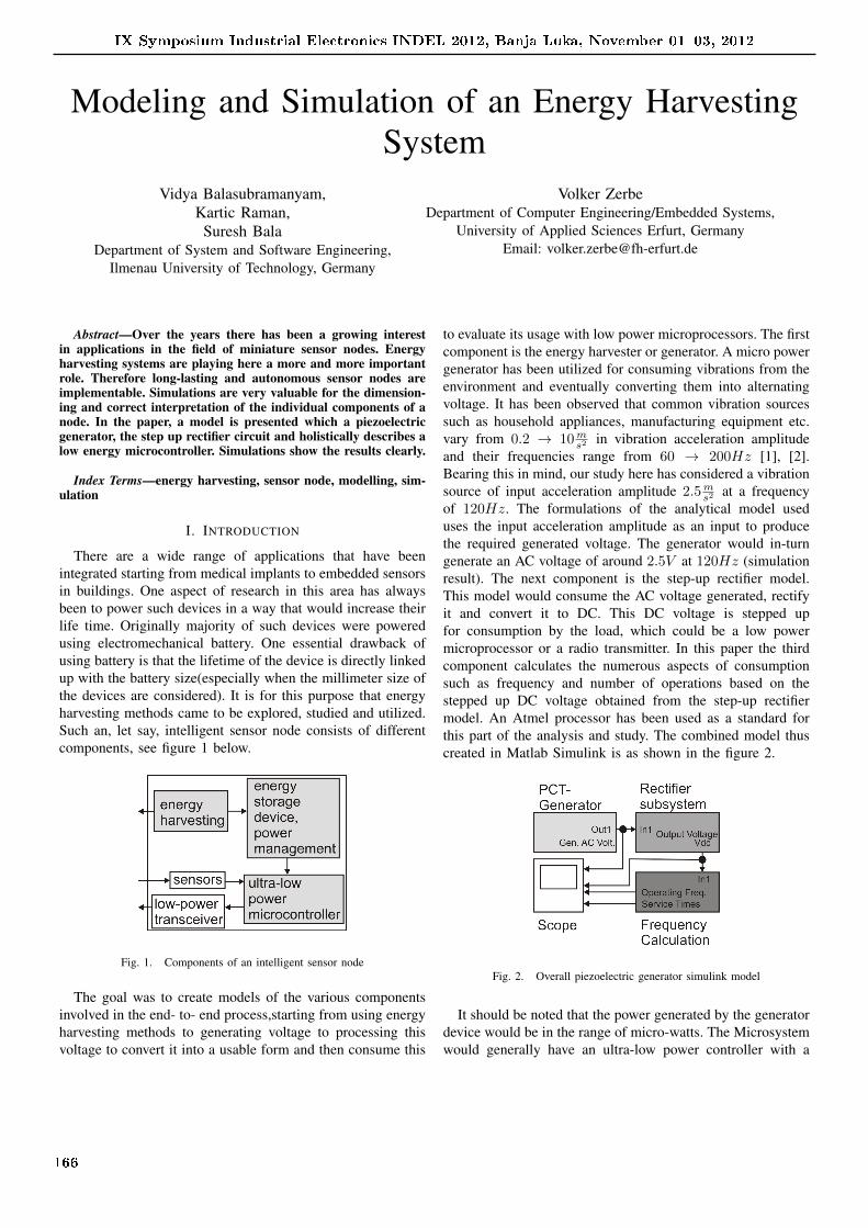
There are a wide range of applications that have beenintegrated starting from medical implants to embedded sensorsin buildings. One aspect of research in this area has alwaysbeen to power such devices in a way that would increase theirlife time. Originally majority of such devices were poweredusing electromechanical battery. One essential drawback ofusing battery is that the lifetime of the device is directly linkedup with the battery size(especially when the millimeter size ofthe devices are considered). It is for this purpose that energyharvesting methods came to be explored, studied and utilized.Such an, let say, intelligent sensor node consists of differentcomponents, see figure 1 below.
Fig. 1. Components of an intelligent sensor node
The goal was to create models of the various componentsinvolved in the end- to- end process,starting from using energyharvesting methods to generating voltage to processing thisvoltage to convert it into a usable form and then consume this
to evaluate its usage with low power microprocessors. The firstcomponent is the energy harvester or generator. A micro powergenerator has been utilized for consuming vibrations from theenvironment and eventually converting them into alternatingvoltage. It has been observed that common vibration sourcessuch as household appliances, manufacturing equipment etc.vary from 0.2 → 10m
s2 in vibration acceleration amplitudeand their frequencies range from 60 → 200Hz [1], [2].Bearing this in mind, our study here has considered a vibrationsource of input acceleration amplitude 2.5m
s2 at a frequencyof 120Hz. The formulations of the analytical model useduses the input acceleration amplitude as an input to producethe required generated voltage. The generator would in-turngenerate an AC voltage of around 2.5V at 120Hz (simulationresult). The next component is the step-up rectifier model.This model would consume the AC voltage generated, rectifyit and convert it to DC. This DC voltage is stepped upfor consumption by the load, which could be a low powermicroprocessor or a radio transmitter. In this paper the thirdcomponent calculates the numerous aspects of consumptionsuch as frequency and number of operations based on thestepped up DC voltage obtained from the step-up rectifiermodel. An Atmel processor has been used as a standard forthis part of the analysis and study. The combined model thuscreated in Matlab Simulink is as shown in the figure 2.
Fig. 2. Overall piezoelectric generator simulink model
It should be noted that the power generated by the generatordevice would be in the range of micro-watts. The Microsystemwould generally have an ultra-low power controller with a
IX Symposium Industrial Electronics INDEL 2012, Banja Luka, November 01�03, 2012
166
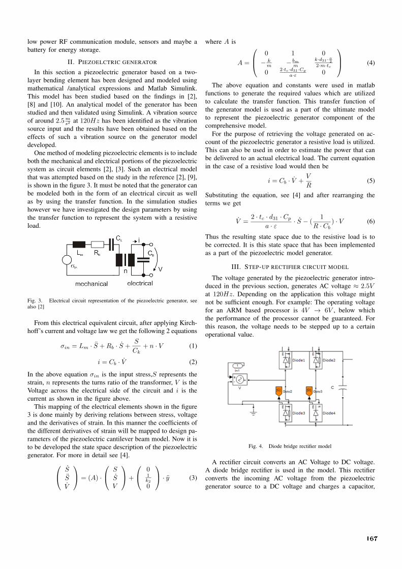
low power RF communication module, sensors and maybe abattery for energy storage.
II. PIEZOELCTRIC GENERATOR
In this section a piezoelectric generator based on a two-layer bending element has been designed and modeled usingmathematical /analytical expressions and Matlab Simulink.This model has been studied based on the findings in [2],[8] and [10]. An analytical model of the generator has beenstudied and then validated using Simulink. A vibration sourceof around 2.5m
s2 at 120Hz has been identified as the vibrationsource input and the results have been obtained based on theeffects of such a vibration source on the generator modeldeveloped.
One method of modeling piezoelectric elements is to includeboth the mechanical and electrical portions of the piezoelectricsystem as circuit elements [2], [3]. Such an electrical modelthat was attempted based on the study in the reference [2], [9],is shown in the figure 3. It must be noted that the generator canbe modeled both in the form of an electrical circuit as wellas by using the transfer function. In the simulation studieshowever we have investigated the design parameters by usingthe transfer function to represent the system with a resistiveload.
Fig. 3. Electrical circuit representation of the piezoelectric generator, seealso [2]
From this electrical equivalent circuit, after applying Kirch-hoff’s current and voltage law we get the following 2 equations
σin = Lm · S +Rb · S +S
Ck+ n · V (1)
i = Cb · V (2)
In the above equation σin is the input stress,S represents thestrain, n represents the turns ratio of the transformer, V is theVoltage across the electrical side of the circuit and i is thecurrent as shown in the figure above.
This mapping of the electrical elements shown in the figure3 is done mainly by deriving relations between stress, voltageand the derivatives of strain. In this manner the coefficients ofthe different derivatives of strain will be mapped to design pa-rameters of the piezoelectric cantilever beam model. Now it isto be developed the state space description of the piezoelectricgenerator. For more in detail see [4].
S
S
V
= (A) ·
S
SV
+
01k2
0
· y (3)
where A is
A =
0 1 0
− km − bm
m
k·d31· a22·m·tc
02·tc·d31·Cp
a·ε 0
(4)
The above equation and constants were used in matlabfunctions to generate the required values which are utilizedto calculate the transfer function. This transfer function ofthe generator model is used as a part of the ultimate modelto represent the piezoelectric generator component of thecomprehensive model.
For the purpose of retrieving the voltage generated on ac-count of the piezoelectric generator a resistive load is utilized.This can also be used in order to estimate the power that canbe delivered to an actual electrical load. The current equationin the case of a resistive load would then be
i = Cb · V +V
R(5)
Substituting the equation, see [4] and after rearranging theterms we get
V =2 · tc · d31 · Cp
a · ε · S − (1
R · Cb) · V (6)
Thus the resulting state space due to the resistive load is tobe corrected. It is this state space that has been implementedas a part of the piezoelectric model generator.
III. STEP-UP RECTIFIER CIRCUIT MODEL
The voltage generated by the piezoelectric generator intro-duced in the previous section, generates AC voltage ≈ 2.5Vat 120Hz. Depending on the application this voltage mightnot be sufficient enough. For example: The operating voltagefor an ARM based processor is 4V → 6V , below whichthe performance of the processor cannot be guaranteed. Forthis reason, the voltage needs to be stepped up to a certainoperational value.
Fig. 4. Diode bridge rectifier model
A rectifier circuit converts an AC Voltage to DC voltage.A diode bridge rectifier is used in the model. This rectifierconverts the incoming AC voltage from the piezoelectricgenerator source to a DC voltage and charges a capacitor,
167
which then serves as the DC voltage source for the rest of thecircuit.
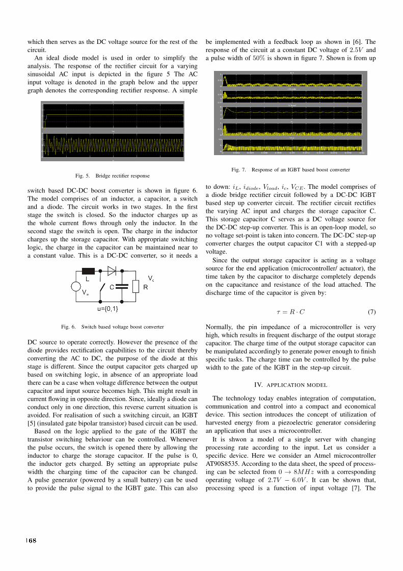
An ideal diode model is used in order to simplify theanalysis. The response of the rectifier circuit for a varyingsinusoidal AC input is depicted in the figure 5 The ACinput voltage is denoted in the graph below and the uppergraph denotes the corresponding rectifier response. A simple
Fig. 5. Bridge rectifier response
switch based DC-DC boost converter is shown in figure 6.The model comprises of an inductor, a capacitor, a switchand a diode. The circuit works in two stages. In the firststage the switch is closed. So the inductor charges up asthe whole current flows through only the inductor. In thesecond stage the switch is open. The charge in the inductorcharges up the storage capacitor. With appropriate switchinglogic, the charge in the capacitor can be maintained near toa constant value. This is a DC-DC converter, so it needs a
Fig. 6. Switch based voltage boost converter
DC source to operate correctly. However the presence of thediode provides rectification capabilities to the circuit therebyconverting the AC to DC, the purpose of the diode at thisstage is different. Since the output capacitor gets charged upbased on switching logic, in absence of an appropriate loadthere can be a case when voltage difference between the outputcapacitor and input source becomes high. This might result incurrent flowing in opposite direction. Since, ideally a diode canconduct only in one direction, this reverse current situation isavoided. For realisation of such a switching circuit, an IGBT[5] (insulated gate bipolar transistor) based circuit can be used.
Based on the logic applied to the gate of the IGBT thetransistor switching behaviour can be controlled. Wheneverthe pulse occurs, the switch is opened there by allowing theinductor to charge the storage capacitor. If the pulse is 0,the inductor gets charged. By setting an appropriate pulsewidth the charging time of the capacitor can be changed.A pulse generator (powered by a small battery) can be usedto provide the pulse signal to the IGBT gate. This can also
be implemented with a feedback loop as shown in [6]. Theresponse of the circuit at a constant DC voltage of 2.5V anda pulse width of 50% is shown in figure 7. Shown is from up
Fig. 7. Response of an IGBT based boost converter
to down: iL, idiode, Vload, ic, VCE . The model comprises ofa diode bridge rectifier circuit followed by a DC-DC IGBTbased step up converter circuit. The rectifier circuit rectifiesthe varying AC input and charges the storage capacitor C.This storage capacitor C serves as a DC voltage source forthe DC-DC step-up converter. This is an open-loop model, sono voltage set-point is taken into concern. The DC-DC step-upconverter charges the output capacitor C1 with a stepped-upvoltage.
Since the output storage capacitor is acting as a voltagesource for the end application (microcontroller/ actuator), thetime taken by the capacitor to discharge completely dependson the capacitance and resistance of the load attached. Thedischarge time of the capacitor is given by:
τ = R · C (7)
Normally, the pin impedance of a microcontroller is veryhigh, which results in frequent discharge of the output storagecapacitor. The charge time of the output storage capacitor canbe manipulated accordingly to generate power enough to finishspecific tasks. The charge time can be controlled by the pulsewidth to the gate of the IGBT in the step-up circuit.
IV. APPLICATION MODEL
The technology today enables integration of computation,communication and control into a compact and economicaldevice. This section introduces the concept of utilization ofharvested energy from a piezoelectric generator consideringan application that uses a microcontroller.
It is shwon a model of a single server with changingprocessing rate according to the input. Let us consider aspecific device. Here we consider an Atmel microcontrollerAT90S8535. According to the data sheet, the speed of process-ing can be selected from 0 → 8MHz with a correspondingoperating voltage of 2.7V − 6.0V . It can be shown that,processing speed is a function of input voltage [7]. The
168

function for a specific processor in question is shown below:
V =Vt
1− C1 · f(8)
Alternatively the operating frequency can be calculated as:
f =1
C1(1− Vt
V )(9)
Where, f is the processing speed in MHz, V is the inputvoltage, Vt is the reference voltage, the minimum operat-ing voltage and C1 is a device specific constant. For theAT90S8535, Vt = 2V and C1 = 0.0833 On the other hand,the energy the processor consumes to process a job can beexpressed by the following formula:
P = C2 ·N · V 2 (10)
Where, C2 = 0.4167 · 10−3 is a device dependent constant,N is the number of operations needed to process the job (inmillion operations), V is the input voltage and P is the energyusage (in Joules), see also [7]. Therefore, we can calculate thenumber of operations by
N =P
C2(V 2). (11)
The equivalent simulink model is shown below, figure 8.
Fig. 8. Simulink model of equation 11
V. SIMULATION STUDIES
This section studies the behaviour of the over-all combinedpiezoelectric generator model based on an PZT5H with a brasscentre shim. For usability analysis the model is combined withan Atmel microcontroller model.
Figure 9 shows the simulation results for the whole model.The microcontroller starts working only when the generatedvoltage due to harvested energy falls in the operating voltagerange of the 2.7V − 8V . For simplicity of analysis, no actualload is attached to the generator system and the output valuesare used for the calculation of processor operating frequency.As output voltage increases, the speed of operation of the mi-crocontroller also increases based on the relation mentioned inequation above. Service time of jobs is inversely proportionalto the operating frequency. In a simulation time of 3 secondsand the piezoelectric generator vibrating at a frequency of120 Hz produced approximately 3.15 Volts resulting in anoperating frequency of approximately 4.38 MHz.
Fig. 9. Overall model simulation results at 120 Hz
From up to down is shown the output voltage, the operatingfrequency, the service time and finally the generated ACVoltage.
At an environmental vibration of frequency 60Hz, the out-put voltage rises faster reaching approximately 4.23V Volts,resulting in faster operation of the microcontroller reaching anoperating frequency of approximately 6.57MHz.
VI. CONCLUSION
There is a wide potential for application of vibration-basedpower supply systems to wireless systems. From amongst the3 technologies present - electromagnetic, piezoelectric andelectrostatic, piezoelectric energy harvesting devices are thesimplest means of scavenging power directly from structuralvibrations. Thus this sort of device was studied and modeledwith a view to develop an end-to-end structure for the purposeof having a one stop station to perform further experiments andstudies. Various tests can be performed using this model byvarying:
• the vibration amplitude or frequency of ambient vibra-tions
• the design parameters of the piezoelectric generatormodel
• the rectifier circuit parameters such as pulse width ofthe gate signal (charging time of the capacitor), forwardvoltage of the diode etc.
• the potential to alter operational voltage range, processorspecific constants.
The model ultimately allows analyzing the generated outputvoltage based on ambient vibrations, operating frequency ofthe processor and service times of the incoming jobs. There arealso provisions and output Graphs generated for the purposeof analyzing the behavior of the DC voltage converted fromvarying input AC voltage generated at 60Hz and 120Hz. Theeventual analysis of the outputs obtained and the presence ofa one stop end-to-end model allows the designer to perform
169

a comprehensive study about utilizing the harvested voltageby different types of microprocessors. The parameters suchas operating frequency output and service time output alsoprovides the designer an option to understand what type micro-system can be adapted to appropriately fit into the harvestedenergy based on numerous application requirements.
REFERENCES
[1] N. E. Toit, Modeling and Design of a MEMS Piezoelectric vibrationenergy harvester. Department of Aeronautical Engineering, MassachusettsInstitute of Technology. 2005
[2] S. Roundy, P.K. Wright, A piezoelectric vibration based generator forwireless electronics. Institute of Physics Publishing, Smart Materials andStructures. 2004
[3] S Basrour, K Matou, Multi-domain and mixed-signal simulation of SOCembedded MEMS. Thermal, Mechanical and Multiphysics Simulationand Experiments in Micro-Electronics and Micro-Systems. 2006. Eu-roSime 2006.
[4] V. Balasubramanyam, K. Raman, S. Bala, Energy Harvesting. ResearchProject, Ilmenau University of Technology. 2012
[5] S P Beeby, R N Torah, M J Tudor, ”A micro electromagnetic generatorfor vibration energy harvesting”-Institute of Physics Publishing, Journalof Micromechanics and Micro-engineering 2007
[6] Configurable Simulink model for DC-DC conversion(http://www.mathworks.com/matlabcentral/fileexchange/18833-configurable-simulink-model-for-dc-dc-converters-with-pwm-pi-control)
[7] Wei Li, Christos G. Cassandras, and Michael Clune, Model-Based De-sign of a Dynamic Voltage scaling controller based on online gradientestimation using SimEvents. Proceedings of the 45th IEEE Conferenceon Decision & Control. San Diego, 2006
[8] S. Basrour, Micro and Nano Systems. TIMA - Annual Report 2008[9] Vinod R Challa, M G Prasad, Yong Shi, Frank T Fisher, A vibration en-
ergy harvesting device with bi-directional resonance frequency tenability.Institute of Physics Publishing, Smart Materials and Structures 2007
[10] Jyoti K Ajitsaria. MODELING AND ANALYSIS OF PZT MICROP-OWER GENERATOR. Auburn University, Alabama, 2008
170


![Modeling, Simulation, and Implementation of a Solar ... · Modeling, Simulation, and Implementation of a Solar Thermoelectric Energy Harvesting System 297 absence [2]. Since solar](https://img.pdfslide.us/doc/110x75/5ed762691b0ef37b614455e1/modeling-simulation-and-implementation-of-a-solar-modeling-simulation-and.jpg)