Embed Size (px)
Citation preview
J. M. McElhaney
A. Palazzolo
Department of Mechanical Engineering, Texas A&M University,
College Station, TX 77843
A. Kascak US Army at NASA-Lewis,
Cleveland, OH 44135
Modeling and Simulation Methods for MDOF Structures and Rotating Machinery With Impact Dampers Previously published work on applied impact damping typically relates to SDOF models or simple MDOF models such as the classical cantilever beam. Structural models often require an extremely large number of DOF with mode shapes that are generally very complex. Dynamics simulation of these typically becomes both complicated and time consuming. The nonlinear behavior of impact dampers further complicates such simulation in that standard linear solutions are not possible. The primary objective in this research extends previous work by applying impact dampers to MDOF structures that are modeled with general three-dimensional ' 'beam'' finite elements. Modal-based models of the MDOF systems and efficient impact damper tracking algorithms were also developed that significantly reduced CPU time for simulation. Significant among the objectives was obtaining an impact damper design for the MDOF casing structure of the Space Shuttle Main Engine (SSME), High-Pressure Oxygen Turbo-Pump (HPOTP), subject to pump rotor shaft unbalance. Impact damper performance is based on suppression of vibration at casing critical frequencies for rotor speed ranges, at rotor full speed, and very high unbalance to simulate a defect such as losing an impeller blade fragment or a cracked bearing [6]. Simulations show significant reductions in vibration at the casing critical frequencies and very high unbalance levels while little or no improvement was observed off resonance. Additionally, the previous work with an experimental rotor bearing system (RBS) and impact damper was modeled using the developed modal-based methods. Simulation of the resulting model response shows remarkable agreement with the experimental. Finally, both the RBS and the HPOTP were modeled and simulated as unstable systems with attached impact dampers. The simulations predict that the impact damper is an excellent stabilizing mechanism for a range of instability driver values. Simulation of the models in this research with the developed modal based algorithms were accomplished with excellent efficiency, and accurate results.
1 Introduction
Most practical structural models require MDOF representation for accurate simulation results. Thus the current work extends impact damper modeling to MDOF systems. All models for this work are developed with three-dimensional "beam" finite elements. One MDOF structure developed in this work is the space shuttle main engine, high-pressure oxygen turbo-pump (HPOTP) casing.
Small HPOTP rotor unbalance causes vibration of the casing, which can be significantly amplified at critical frequencies or with a small defect such as the loss of an impeller fragment. The vibration can be reduced by adapting some form of damping to the casing, which is difficult given the lack of space for attachment and the extreme temperature environment. One solution to this problem is to adapt an impact damper to the pump casing.
The impact damper consists of a housing cavity fixed to a structure with an internal impactor that moves relative to the cavity walls. Collisions between the housing and impactor attenuate vibration by dissipating the structure's kinetic energy. An advantage of the impact damper is that it is an inertial device,
Contributed by the International Gas Turbine Institute and presented at the 40th International Gas Turbine and Aeroengine Congress and Exhibition, Houston, Texas, June 5-8, 1995. Manuscript received by the International Gas Turbine Institute March 2, 1995. Paper No. 95-GT-397. Associate Technical Editor: C. J. Russo.
as opposed to conventional dampers, which require an attachment to ground. Considering temperature constraints, previous work by Nale and Klusman [1], and Moore and Palazzolo [2] confirms the effectiveness of the impact damper in high and cryogenic temperature environments, respectively. In addition, Radii and Palazzolo show only small variation in the COR as a function of temperature and impact velocity for readily available materials. Considering these advantages, the impact damper should serve as an ideal retrofit device.
The focus of this work will thus be to model and simulate MDOF structures with impact dampers to determine their benefits in vibration. Correlation studies of previous work [2] with impact dampers applied to a SDOF oscillator and an experimental RBS with flexible bearing supports are conducted. HPOTP reduction in vibration at casing critical frequencies, at steady rotor speed, and high levels of rotor unbalance with impact dampers is investigated as well.
Simulating a time response for large DOF systems often requires CPU time that is very impractical. This provided the motivation to develop an efficient modal-based method for simulating the impact damper with general MDOF systems. Since steady-state, nonlinear solutions such as the Harmonic Balance or Collocation methods require iterative searches within the clearance of the impact damper, the frequency response was then obtained by conducting transient forced responses out to a steady amplitude for a range of frequencies. The improvement in simulation efficiency of modal-based solutions would then
436 / Vol. 119, APRIL 1997 Transactions of the ASME
Copyright © 1997 by ASME
Downloaded From: http://asmedigitalcollection.asme.org/ on 04/08/2015 Terms of Use: http://asme.org/terms
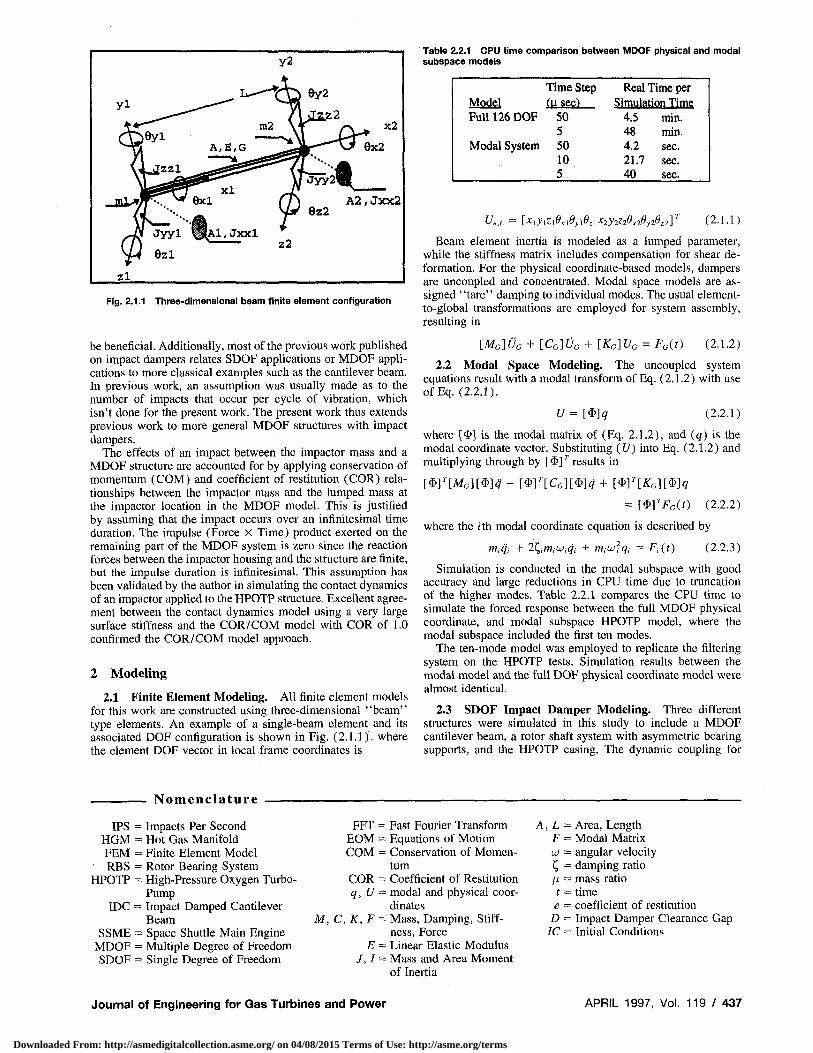
Table 2.2.1 CPU time comparison between MDOF physical and modal subspace models
Fig. 2.1.1 Three-dimensional beam finite element configuration
be beneficial. Additionally, most of the previous work published on impact dampers relates SDOF applications or MDOF applications to more classical examples such as the cantilever beam. In previous work, an assumption was usually made as to the number of impacts that occur per cycle of vibration, which isn't done for the present work. The present work thus extends previous work to more general MDOF structures with impact dampers.
The effects of an impact between the impactor mass and a MDOF structure are accounted for by applying conservation of momentum (COM) and coefficient of restitution (COR) relationships between the impactor mass and the lumped mass at the impactor location in the MDOF model. This is justified by assuming that the impact occurs over an infinitesimal time duration. The impulse (Force X Time) product exerted on the remaining part of the MDOF system is zero since the reaction forces between the impactor housing and the structure are finite, but the impulse duration is infinitesimal. This assumption has been validated by the author in simulating the contact dynamics of an impactor applied to the HPOTP structure. Excellent agreement between the contact dynamics model using a very large surface stiffness and the COR/COM model with COR of 1.0 confirmed the COR/COM model approach.
2 Modeling
2.1 Finite Element Modeling. All finite element models for this work are constructed using three-dimensional ' 'beam'' type elements. An example of a single-beam element and its associated DOF configuration is shown in Fig. (2.1.1). where the element DOF vector in local frame coordinates is
Time Step Real Time per Model (usee} Simulation Time Full 126 DOF 50 4.5 min.
5 48 min. Modal System 50 4.2 sec.
10 21.7 sec. 5 40 sec.
Ue,L = [XiylzAlOylO,.lX2y2Z20x2Oy28zl] (2.1.1)
Beam element inertia is modeled as a lumped parameter, while the stiffness matrix includes compensation for shear deformation. For the physical coordinate-based models, dampers are uncoupled and concentrated. Modal space models are assigned "tare" damping to individual modes. The usual element-to-global transformations are employed for system assembly, resulting in
[MG]UG + [CG]0G + [KC]UG = Fc(t) (2.1.2)
2.2 Modal Space Modeling. The uncoupled system equations result with a modal transform of Eq. (2.1.2) with use ofEq. (2.2.1).
[/ = [*]<? (2.2.1)
where [<&] is the modal matrix of (Eq. 2.1.2), and (g) is the modal coordinate vector. Substituting (U) into Eq. (2.1.2) and multiplying through by [ $]T results in
mT[MG][$]cj + mr[cG][$]<i + mT[KG)mq = mrFc(t) (2.2.2)
where the z'th modal coordinate equation is described by
m,# + 2^,m,w,^ + rriiUjUi = ^,(0 (2.2.3)
Simulation is conducted in the modal subspace with good accuracy and large reductions in CPU time due to truncation of the higher modes. Table 2.2.1 compares the CPU time to simulate the forced response between the full MDOF physical coordinate, and modal subspace HPOTP model, where the modal subspace included the first ten modes.
The ten-mode model was employed to replicate the filtering system on the HPOTP tests. Simulation results between the modal model and the full DOF physical coordinate model were almost identical.
2.3 SDOF Impact Damper Modeling. Three different structures were simulated in this study to include a MDOF cantilever beam, a rotor shaft system with asymmetric bearing supports, and the HPOTP casing. The dynamic coupling for
Nomenclature
IPS = Impacts Per Second HGM = Hot Gas Manifold FEM = Finite Element Model RBS = Rotor Bearing System
HPOTP = High-Pressure Oxygen Turbo-Pump
IDC = Impact Damped Cantilever Beam
SSME = Space Shuttle Main Engine MDOF = Multiple Degree of Freedom SDOF = Single Degree of Freedom
M, C
FFT = Fast Fourier Transform A, L = Area, Length EOM = Equations of Motion F = Modal Matrix COM = Conservation of Momen UJ = angular velocity
tum C, = damping ratio COR = Coefficient of Restitution \i = mass ratio q, U = modal and physical coor t = time
dinates e = coefficient of restitution K, F = Mass, Damping, Stiff D = Impact Damper Clearance Gap
ness, Force IC = Initial Conditions E = Linear Elastic Modulus
J, I = Mass and Area Moment of Inertia
Journal of Engineering for Gas Turbines and Power APRIL 1997, Vol. 119 / 437
Downloaded From: http://asmedigitalcollection.asme.org/ on 04/08/2015 Terms of Use: http://asme.org/terms
Housing Impactor
Attachment Structure
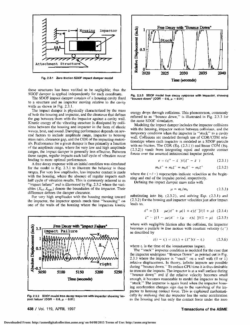
Fig. 2.3.1 Zero friction SDOF impact damper model
these structures has been verified to be negligible; thus the SDOF damper is applied independently for each coordinate.
The SDOF impact damper consists of a housing cavity fixed to a structure and an impactor moving relative to the cavity walls as shown in Fig. 2.3.1.
The impact damper is physically characterized by the mass of both the housing and impactor, and the clearance that defines the gap between them with the impactor against a cavity wall. Kinetic energy of the vibrating structure is dissipated by collisions between the housing and impactor in the form of elastic waves, heat, and sound. Damping performance depends on several factors to include amplitude range, impactor to housing mass ratio, clearance gap, and the COR of the impacting materials. Performance for a given damper is thus primarily a function of the amplitude range, where for very low and high amplitude ranges, the impact damper is generally less effective. Between these ranges, regular impacts each half cycle of vibration occur leading to more optimal performance.
A free decay response with an initial condition was simulated for the model in Fig. 2.3.1 to illustrate the behavior in these ranges. For very low amplitudes, less impactor contact is made with the housing, where the absence of regular impacts each half cycle of vibration results. This is commonly referred to as "impact failure" and is illustrated by Fig. 2.3.2 where the variables (XieU XIigU) denote the boundaries of the impactor. Their difference defines the damper clearance.
For very high amplitudes with the housing moving toward the impactor, the impactor spends much time "bouncing" on one of the walls of the housing where the impactors kinetic
1.5
-0.5
Free Decay with "Impact Faflure" Impact Failure
I'lnlii,.", '1 / \ « / \ « W .\7 \ -Wwwv right
5050 5100 5150 5200
Time (seconds)
5250
Fig. 2.3.2 SDOF model free decay response with impactor showing 'impact failure' (COR = 0.6, /x = 0.01)
Free Decay with "Bounce Down"
2020 2025 2030 2035 2040
Time (seconds)
Fig. 2.3.3 SDOF model free decay response with impactor, showing "bounce down" (COR = 0.6, n = 0.01)
energy drops through collisions. This phenomenon, commonly referred to as "bounce down," is illustrated in Fig. 2.3.3 for the same SDOF simulation.
Modeling the impact damper includes the impactor collisions with the housing, impactor motion between collisions, and the temporary condition when the impactor is "stuck" to a cavity wall. Collisions are modeled through use of COR/COM relationships where each impactor is modeled as a SDOF particle with no friction. The COR (Eq. (2.3.1)) and linear COM (Eq. (2.3.2)) result from integrating equal and opposite contact forces over the assumed infinitesimal impulse period,
e = (z+ - x + )/(z- - x~) (2.3.1)
m,,x~ + m,z" = mhx + + mii + (2.3.2)
where the (+ / - ) superscripts indicate velocities at the beginning and end of the impulse period, respectively.
Defining the impact damper mass ratio with
fj, = milmh (2.3.3)
substituting into Eq. (2.3.2), and solving Eqs. (2.3.1) and (2.3.2) for the housing and impactor velocities just after impact leads to,
x+ = [(1 - ne)x- + n(l + e ) z - ] / ( l + fj.) (2.3.4)
z'+ = [(1 - ne)x- + (M - e)i~]/(l + //> (2.3.5)
where with negligible friction after the collision, the impactor becomes a particle in free motion with constant velocity (z + ) as described by
z(t - t,) = z(.t,) + (i+)(t - t,) (2.3.6)
where t, is the time of the instantaneous impact. The "stuck" impactor condition is modeled for the case that
the impactor undergoes "Bounce Down" as pointed out in Fig. 2.3.3 where the impactor is "stuck" on a wall with (0 or 1) relative displacement. In theory, infinite impacts are possible during ' 'bounce down." To reduce CPU time it is thus desirable to truncate the impacts. The impactor is at a wall surface during "bounce down" and if the relative velocity becomes small enough, it becomes reasonable to model the impactor as being "stuck." The impactor is again freed when the impactor housing acceleration changes sign due to the vanishing of the impactor to housing contact force. This is explained mathematically by realizing that the impactor has the same acceleration as the housing and has only the contact force under the zero
438 / Vol. 119, APRIL 1997 Transactions of the ASME
Downloaded From: http://asmedigitalcollection.asme.org/ on 04/08/2015 Terms of Use: http://asme.org/terms
friction assumption. Since the impactor has the same acceleration as the housing, the contact force changes sign when the acceleration changes sign. The impactor then continues with the velocity that the housing had at the time the contact force vanished.
The ' 'stuck'' condition is invoked if a second impact occurs on one wall within (0.2 percent) of the period of the highest frequency considered significant in the simulation. An example of this is the simulation of a structure with impact damper where only the first ten lower modes significantly contribute to the response. If the 10th natural frequency is 1000 Hz, its period is 1 ms. On "bounce down," a "stuck" impactor would then be invoked if a second impact occurred within 0.2 percent of this period or 2 /is. This criterion has been verified as a conservative assumption.
For simulation in the physical coordinate space, the "stuck" impactor mass is simply added to the inertia matrix. For modal subspace simulation it becomes necessary to store a complete additional set of modal system parameters, that is modal mass, stiffness, damping, and force. The "free" and "stuck" impactor condition thus requires two different modal subspaces for the simulation since the added mass for the "stuck" condition produces a different modal system. This results in two respective sets of physical coordinates as stated by,
Uf =[$/]% (free coordinates) (2.3.7)
Us = [$s]q.< (stuck coordinates) (2.3.8)
When transitioning from "free" to "stuck," integration of modal equations switches to the ' 'stuck'' set of equations, which require new initial conditions for the modal coordinates (qs). Similarly, when transitioning from "stuck" to "free," integration of the "free" modal equations is initiated and new initial conditions for the modal coordinates (qf) are required. Obtaining the transforms leading to the initial conditions begins with obtaining the transform from physical to modal coordinates. For the "free" system coordinates the procedure begins with an identity (2.3.9),
[Mf]U,= [Mf][$f]qf (2.3.9)
where [Mf] is the physical coordinate mass matrix. Equation (2.3.9) is next premultiplied by [ $ / ] r to yield Eq. (2.3.10),
[®f]T[Mf]Uf= [®f]
T[Mf][<S>f]qf
diag(m,) = [*/] r[Af /][* /] ,
'free' modal mass matrix. (2.3.10)
Solving Eq. (2.3.10) for (qf) yields the transform,
If = AU„
A = diag ( l / m / ) * [ $ / ]r [ M / ] (2.3.11)
The same procedure results in obtaining "stuck" modal coordinates in terms of "stuck" physical coordinates and is described by
q, = BU„
B = diag(l /m. t)*[*v] r[M I] (2.3.12)
To obtain the transform between "stuck" and "free" modal coordinates, the two modal expansions (2.3.7) and (2.3.8) are equated at the instant the impactor is "stuck" or "freed." Substituting (Us) of Eq. (2.3.8) into Eq. (2.3.11), and (Uf) of Eq. (2.3.7) into Eq. (2.3.12), results in the transforms:
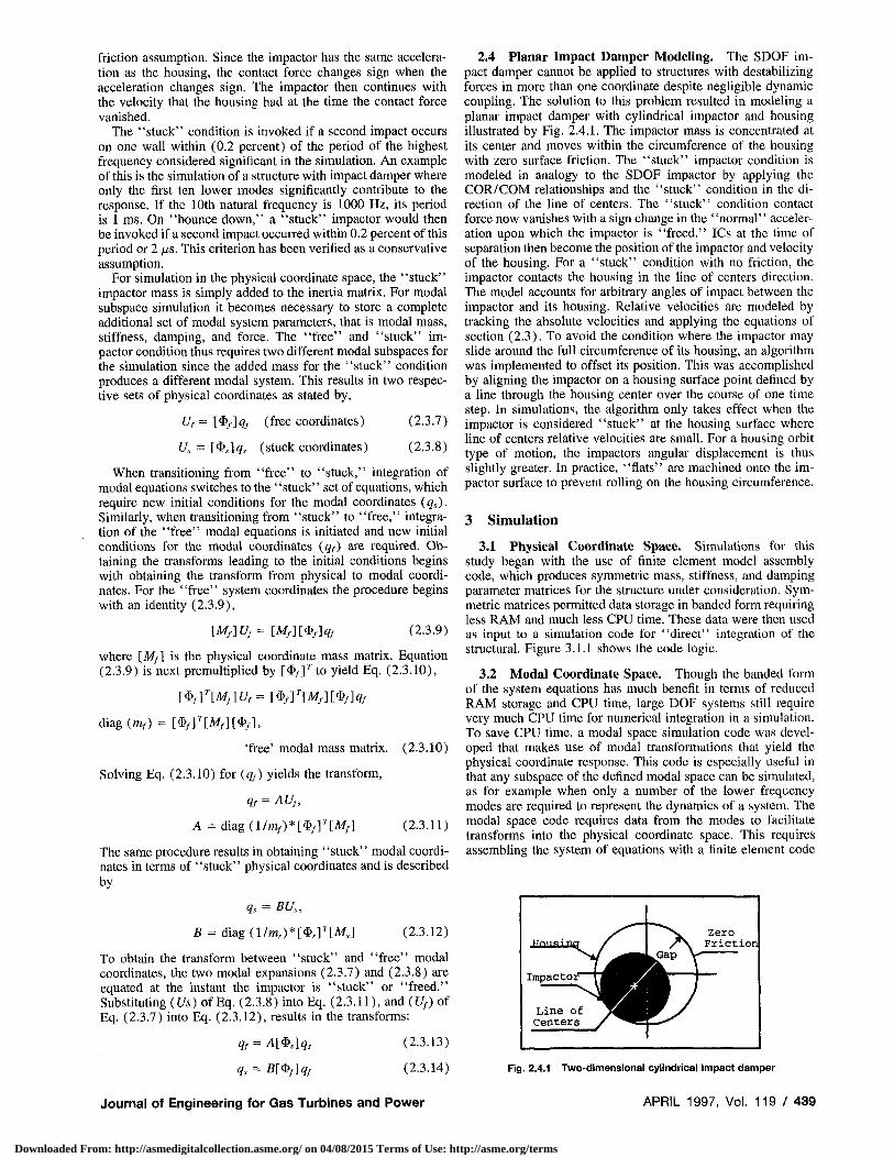
2.4 Planar Impact Damper Modeling. The SDOF impact damper cannot be applied to structures with destabilizing forces in more than one coordinate despite negligible dynamic coupling. The solution to this problem resulted in modeling a planar impact damper with cylindrical impactor and housing illustrated by Fig. 2.4.1. The impactor mass is concentrated at its center and moves within the circumference of the housing with zero surface friction. The "stuck" impactor condition is modeled in analogy to the SDOF impactor by applying the COR/COM relationships and the "stuck" condition in the direction of the line of centers. The "stuck" condition contact force now vanishes with a sign change in the ' 'normal'' acceleration upon which the impactor is "freed." ICs at the time of separation then become the position of the impactor and velocity of the housing. For a "stuck" condition with no friction, the impactor contacts the housing in the line of centers direction. The model accounts for arbitrary angles of impact between the impactor and its housing. Relative velocities are modeled by tracking the absolute velocities and applying the equations of section (2.3). To avoid the condition where the impactor may slide around the full circumference of its housing, an algorithm was implemented to offset its position. This was accomplished by aligning the impactor on a housing surface point defined by a line through the housing center over the course of one time step. In simulations, the algorithm only takes effect when the impactor is considered "stuck" at the housing surface where line of centers relative velocities are small. For a housing orbit type of motion, the impactors angular displacement is thus slightly greater. In practice, "flats" are machined onto the impactor surface to prevent rolling on the housing circumference.
3 Simulation
3.1 Physical Coordinate Space. Simulations for this study began with the use of finite element model assembly code, which produces symmetric mass, stiffness, and damping parameter matrices for the structure under consideration. Symmetric matrices permitted data storage in banded form requiring less RAM and much less CPU time. These data were then used as input to a simulation code for "direct" integration of the structural. Figure 3.1.1 shows the code logic.
3.2 Modal Coordinate Space. Though the banded form of the system equations has much benefit in terms of reduced RAM storage and CPU time, large DOF systems still require very much CPU time for numerical integration in a simulation. To save CPU time, a modal space simulation code was developed that makes use of modal transformations that yield the physical coordinate response. This code is especially useful in that any subspace of the defined modal space can be simulated, as for example when only a number of the lower frequency modes are required to represent the dynamics of a system. The modal space code requires data from the modes to facilitate transforms into the physical coordinate space. This requires assembling the system of equations with a finite element code
qJ = A[$s\qs
qs = B[$f]qf
(2.3.13)
(2.3.14)
""""'•"T / ^^V zero
/*\ Friction ^Gap V-
Impactor I^^HlE
Line of 1^^^| Centers / ^^Bl
Fig. 2.4.1 Two-dimensional cylindrical impact damper
Journal of Engineering for Gas Turbines and Power APRIL 1997, Vol. 1 1 9 / 4 3 9
Downloaded From: http://asmedigitalcollection.asme.org/ on 04/08/2015 Terms of Use: http://asme.org/terms
FEM Assembly Code Get M.C.K in Bandec Form
I I t = 0sec
Initialize: X= Displace V = Veloc A= Accel
t+dt
Subroutine: newmarkbetaO Integrate System Equations
Z Accel Sign Change so Contact Force vanishes Tz^-astlmiMCtTime.
Subroutine: impactO 1. Use COR/COM to get new
IC's just after Impact. 2. Adjust to Impact Time (ti)
ti = Current Impact Time x = Last Impact Time dt = Integration Time Step
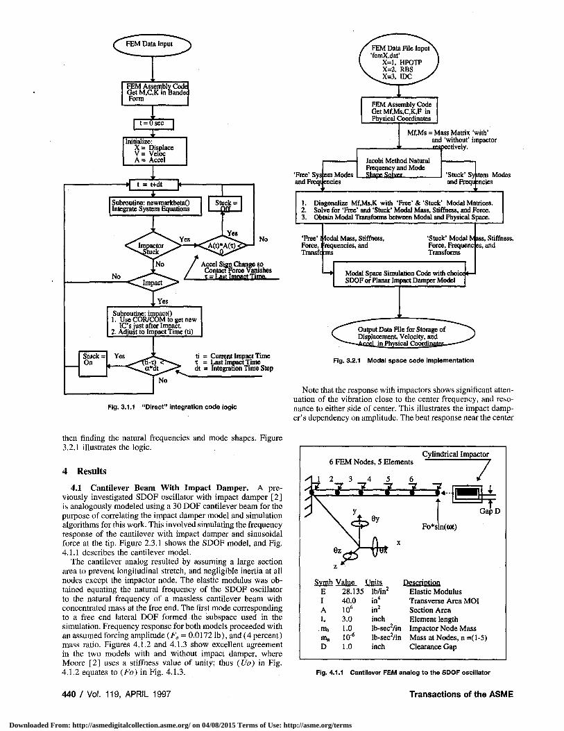
Fig. 3.1.1 "Direct" integration code logic
FEM Assembly Code GetMf,Ms,C,K,Fin Physical Coordinates
'Free' andFreqi
Sysem Modes encies
Mf.Ms = Mass Matrix 'with' and 'without' impactor
____rflspectively.
Jacobi Method Natural Frequency and Mode Shane Snlvnr 'Stuck' Syfctem Modes
and Freqti :ncies
1. DiagonaJize Mf,Ms,K with 'Free'&'Stuck' Modal Matrices. 2. Solve for 'Free' and 'Stuck' Modal Mass, Stiffness, and Force. 3. Obtain Modal Transforms between Modal and Physical Space.
'Free' Force, Transfc rms
I fodal Mass, Stiffness, ] 'requencies, and
'Stuck' Modal Mjass, Force, Frequenc es, Transforms
Modal Space Simulation Code with SDOF or Planar Impact Damper Model
choict <—
Stiffness, and
Output Data File for Storage of Displacement, Velocity, and
in Physical Coordim
Fig. 3.2.1 Modal space code implementation
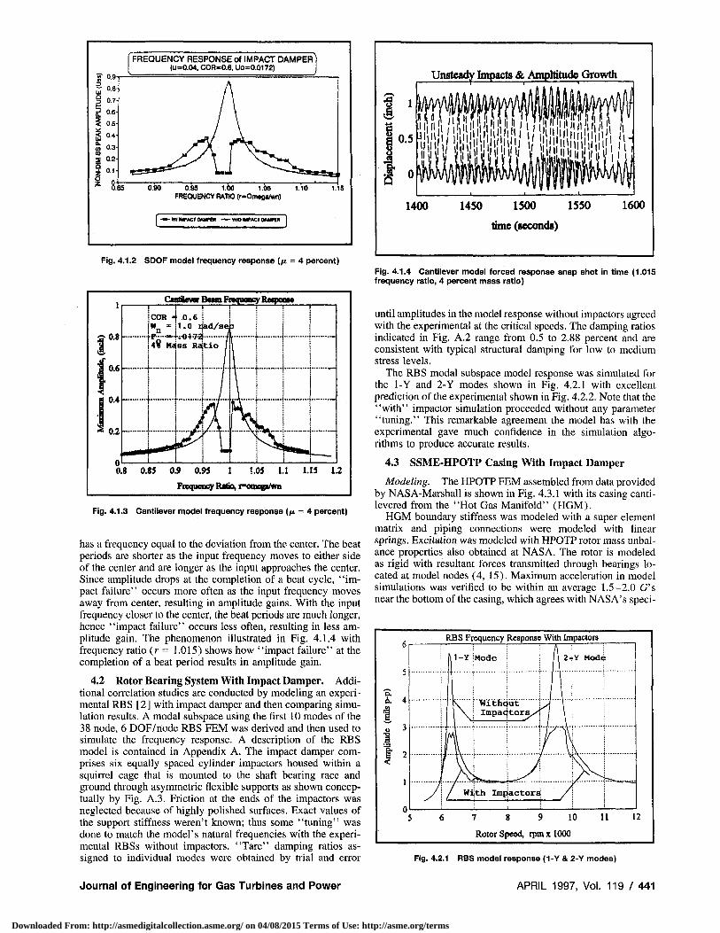
Note that the response with impactors shows significant attenuation of the vibration close to the center frequency, and resonance to either side of center. This illustrates the impact damper's dependency on amplitude. The beat response near the center
then finding the natural frequencies and mode shapes. Figure 3.2.1 illustrates the logic.
4 Results
4.1 Cantilever Beam With Impact Damper. A previously investigated SDOF oscillator with impact damper [2] is analogously modeled using a 30 DOF cantilever beam for the purpose of correlating the impact damper model and simulation algorithms for this work. This involved simulating the frequency response of the cantilever with impact damper and sinusoidal force at the tip. Figure 2.3.1 shows the SDOF model, and Fig. 4.1.1 describes the cantilever model.
The cantilever analog resulted by assuming a large section area to prevent longitudinal stretch, and negligible inertia at all nodes except the impactor node. The elastic modulus was obtained equating the natural frequency of the SDOF oscillator to the natural frequency of a massless cantilever beam with concentrated mass at the free end. The first mode corresponding to a free end lateral DOF formed the subspace used in the simulation. Frequency response for both models proceeded with an assumed forcing amplitude (FB = 0.0172 lb), and (4 percent) mass ratio. Figures 4.1.2 and 4.1.3 show excellent agreement in the two models with and without impact damper, where Moore [2] uses a stiffness value of unity; thus (Uo) in Fig. 4.1.2 equates to (Fo) in Fig. 4.1.3.
440 / Vol. 119, APRIL 1997
6 FEM Nodes, 5 Elements
XI 1 2 3 4 5 6
Cylindrical Impactor
f 7 7 7 Z—£..j 7
T GapD
Fo*sin(o)t)
Svmb Value Units E I A L mi, m„ D
28.135 40.0 106
3.0 1.0 10'6
1.0
lb/in" in4
in2
inch lb-sec2/in lb-sec2/in inch
Description Elastic Modulus Transverse Area MOI Section Area Element length Impactor Node Mass Mass at Nodes, n =(1-5) Clearance Gap
Fig. 4.1.1 Cantilever FEM analog to the SDOF oscillator
Transactions of the ASME
Downloaded From: http://asmedigitalcollection.asme.org/ on 04/08/2015 Terms of Use: http://asme.org/terms
FREQUENCY RESPONSE of IMPACT DAMPER (u=0.04, COR-0.6, Uo=0.0172)
0.95 1.00 1.05 1.10 FREQUENCY RATIO (r-Omega/wn)
-WtfIMPACTOAMrtR -—W/OIMPACTONWCR j
Fig. 4.1.2 SDOF model frequency response (ju = 4 percent)
CmtaewBrBctm Frequency RCTponto
0.8 0.85 0.9 0.93 1 1.05 1.1 1.13
Frequency Ratio, i=omop/wn
1.2
Fig. 4.1.3 Cantilever model frequency response (/u = 4 percent)
has a frequency equal to the deviation from the center. The beat periods are shorter as the input frequency moves to either side of the center and are longer as the input approaches the center. Since amplitude drops at the completion of a beat cycle, "impact failure" occurs more often as the input frequency moves away from center, resulting in amplitude gains. With the input frequency closer to the center, the beat periods are much longer, hence ' 'impact failure'' occurs less often, resulting in less amplitude gain. The phenomenon illustrated in Fig. 4.1.4 with frequency ratio (r = 1.015) shows how "impact failure" at the completion of a beat period results in amplitude gain.
4.2 Rotor Bearing System With Impact Damper. Additional correlation studies are conducted by modeling an experimental RBS [2] with impact damper and then comparing simulation results. A modal subspace using the first 10 modes of the 38 node, 6 DOF/node RBS FEM was derived and then used to simulate the frequency response. A description of the RBS model is contained in Appendix A. The impact damper comprises six equally spaced cylinder impactors housed within a squirrel cage that is mounted to the shaft bearing race and ground through asymmetric flexible supports as shown conceptually by Fig. A.3. Friction at the ends of the impactors was neglected because of highly polished surfaces. Exact values of the support stiffness weren't known; thus some "tuning" was done to match the model's natural frequencies with the experimental RBSs without impactors. "Tare" damping ratios assigned to individual modes were obtained by trial and error
Journal of Engineering for Gas Turbines and Power
1 ' Unsteady Impacts & Amplitude Growth
Hiii« !l H in
1400 1450 1500 1550
time (seconds)
1600
Fig. 4.1.4 Cantilever model forced response snap shot in time (1.015 frequency ratio, 4 percent mass ratio)
until amplitudes in the model response without impactors agreed with the experimental at the critical speeds. The damping ratios indicated in Fig. A.2 range from 0.5 to 2.88 percent and are consistent with typical structural damping for low to medium stress levels.
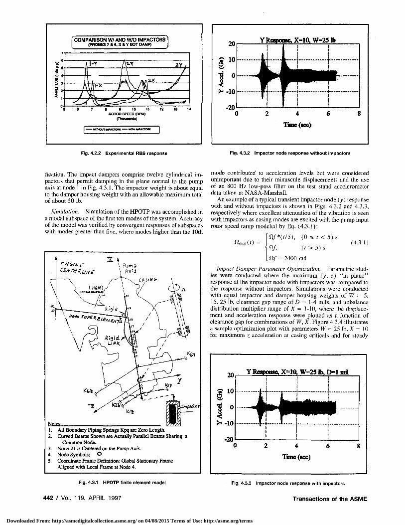
The RBS modal subspace model response was simulated for the 1-Y and 2-Y modes shown in Fig. 4.2.1 with excellent prediction of the experimental shown in Fig. 4.2.2. Note that the "with" impactor simulation proceeded without any parameter "tuning." This remarkable agreement the model has with the experimental gave much confidence in the simulation algorithms to produce accurate results.
4.3 SSME-HPOTP Casing With Impact Damper
Modeling. The HPOTP FEM assembled from data provided by NASA-Marshall is shown in Fig. 4.3.1 with its casing canti-levered from the "Hot Gas Manifold" (HGM).
HGM boundary stiffness was modeled with a super element matrix and piping connections were modeled with linear springs. Excitation was modeled with HPOTP rotor mass unbalance properties also obtained at NASA. The rotor is modeled as rigid with resultant forces transmitted through bearings located at model nodes (4, 15). Maximum acceleration in model simulations was verified to be within an average 1.5-2.0 G's near the bottom of the casing, which agrees with NASA's speci-
RBS Frequency Response With Impactors
7 8 9 10 11
Rotor Speed, rpmxlOOO
Fig. 4.2.1 RBS model response (1-Y & 2-Y modes)
APRIL 1997, Vol. 119/441
Downloaded From: http://asmedigitalcollection.asme.org/ on 04/08/2015 Terms of Use: http://asme.org/terms
COMPARISON W/ AND W/O IMPACTORS (PROBES 7 A 8, X & Y BOT DAMP)
8 9 10 11 ROTOR SPEED (RPM)
(Thouunds)
E wrHOUTMPACTQn • • WITH MP ACTOM
Fig. 4.2.2 Experimental RBS response
20
S 1 0
Y RCTPOMC X=10, W=23 lb
Timc(«c)
Fig. 4.3.2 Impactor node response without impactors
fication. The impact dampers comprise twelve cylindrical impactors that permit damping in the plane normal to the pump axis at node 1 in Fig. 4.3.1. The impactor weight is about equal to the damper housing weight with an allowable maximum total of about 50 lb.
Simulation. Simulation of the HPOTP was accomplished in a modal subspace of the first ten modes of the system. Accuracy of the model was verified by convergent responses of subspaces with modes greater than five, where modes higher than the 10th
1. All Boundary Piping Springs Kpq ate Zero Length. 2. Curved Beams Shown are Actually Parallel Beams Sharing a
Common Node. 3. Node 21 is Centered on the Pump Axis. 4. Node Symbols: O 5. Coordinate Frame Definition: Global Stationary Frame
Aligned with Local Frame at Node 4.
Fig. 4.3.1 HPOTP finite element model
442 / Vol. 119, APRIL 1997
mode contributed to acceleration levels but were considered unimportant due to their minuscule displacements and the use of an 800 Hz low-pass filter on the test stand accelerometer data taken at NASA-Marshall.
An example of a typical transient impactor node (y) response with and without impactors is shown in Figs. 4.3.2 and 4.3.3, respectively where excellent attenuation of the vibration is seen with impactors as casing modes are excited with the pump input rotor speed ramp modeled by Eq. (4.3.1):
^shaft(f) -Qf*U/5), ( 0 s s r < 5 ) s
Qf, (t 5* 5) S
. Qf = 2400 rad
(4.3.1)
Impact Damper Parameter Optimization. Parametric studies were conducted where the maximum (y, z) "in plane" response at the impactor node with impactors was compared to the response without impactors. Simulations were conducted with equal impactor and damper housing weights of W = 5, 15, 25 lb, clearance gap range of D = 1-4 mils, and unbalance distribution multiplier range of X = 1-10, where the displacement and acceleration response were plotted as a function of clearance gap for combinations of W, X. Figure 4.3.4 illustrates a sample optimization plot with parameters W = 25 lb, X = 10 for maximum z acceleration at casing criticals and for steady
Y Response, X-Hfc W=2S lb, F>1 mffl
Fig. 4.3.3 Impactor node response with impactors
Transactions of the ASME
Downloaded From: http://asmedigitalcollection.asme.org/ on 04/08/2015 Terms of Use: http://asme.org/terms
Z Acceleration, W=25 lb, X=10
10,: F u l l _RQ£QX_Speed
-ModQfi 1-
1.5 2 2.5 3 3.5
Clearance D (mils)
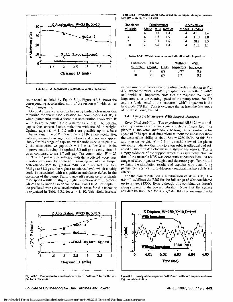
Table 4.3.1 Predicted worst case vibration for impact damper parameters {W = 25 lb, D = 1.7 mil)
Fig. 4.3.4 Z-coordinate acceleration versus clearance
rotor speed modeled by Eq. (4.3.1). Figure 4.3.5 shows the corresponding acceleration ratio of the response ' 'without'' to "with" impactors.
Optimal clearance selection began by finding clearances that minimize the worst case vibration for combinations of W, X where parametric studies show that acceleration levels with W = 25 lb are roughly \ those with for W = 5 lb. The optimal gap is thus chosen from simulations with the 25 lb weight. Optimal gaps (D = 1, 1.7 mils) are possible up to a base unbalance multiple of X = 7 with W = 25 lb. Since acceleration and displacements are significantly lower and do not vary appreciably for this range of gaps below the unbalance multiple X = 7, the most effective gap is D = 1.7 mils. For X = 10 the improvement in using the optimal 3.3 mil gap is only about 3 gs as compared to the 1.7 mil gap. The combination W = 25 lb, D = 1.7 mil is thus selected with the predicted worst case vibration explained by Table 4.3.1 showing remarkable damper performance with the greatest reduction in acceleration from 66.5 gs to 31.2 gs at the highest unbalance level, which notably could be associated with a significant unbalance defect in the operation of the pump. Performance off resonance or at steady rotor speed results in slightly higher vibration with impactors, where the reduction factor can be less than 1.0. An example of the predicted worst case acceleration increase for this behavior ' is explained in Table 4.3.2 for X = 1, 10. This slight increase
Unbalance Displacement Multiple Mode mils Reduct
1 4 0.7 1.4 3 4 1.8 1.9 7 2 3.3 1.8 10 2 6.6 1.4
Acceleration ModeG's Reduct
4 4.1 1.4 4 11.0 1.8 4 18.1 2.5 4 31.2 2.1
Table 4.3.2 Worst case full-speed vibration with impactors
Unbalance Planar Without Multiole Coord Units Impactors
1 z g's 0.77 10 z g's 7.2
With Impactors
0.9 9.1
is the cause of impactors exciting other modes as shown in Fig. 4.3.6 where the "steady state" z displacement is plotted "with" and "without" impactors. Note that the response "without" impactors is at the running speed of the pump rotor, 381 Hz and the fundamental in the response "with" impactors is the first mode (78 Hz). This is evidence that at least the first mode at 77 Hz is being excited.
4.4 Unstable Structures With Impact Dampers
Rotor Shaft Stability. The experimental RBS [2] was modeled by assuming an equal cross coupled stiffness Kcc, "in plane" at the rotor shaft lower bearing. At a constant rotor speed of 7878 rpm, trial simulations without the impactors show the onset of instability at about Kcc = 8250 lb/in. At this Kcc and housing weight, W = 1.5 lb, an axial view of the planar instability indicates that the vibration orbit is elliptical and oriented at about 37 deg clockwise relative to the vertical. This is simply evidence of the support structure's asymmetry. Simulation of the unstable RBS was done with impactors installed for ranges of fee, impactor weight, and clearance gaps. Table 4.4.1 explains the simulation results and explains why quantifying parameters is critical since different combinations have different effects.
For the results obtained, a combination of W = 3 lb, D = 6.9 mil stabilizes the RBS for the full range of Kcc considered up to a max (13500 lb/in), though this combination doesn't always result in the lowest vibration. Note that the system couldn't be stabilized for Kcc greater than the maximum with
N
0
Z Acceleration, W=25 lb, X=10 T • I • ' l I ~ I
= F u l l -Eotor-Sfteed-,
1 1.5 2 2.5 3 3.5 4
Clearance D (mils)
Z Displace, W=251b,X=10J>=lmil Wim Impactors
6.01 6.02 6.03 6.04 6.03
Time (sec)
Fig. 4.3.5 Z -coordinate acceleration ratio of "without" to "with" im- Fig. 4.3.6 Steady-state response "with" and "without" impactors show-pactor's response ing modal excitation
Journal of Engineering for Gas Turbines and Power APRIL 1997, Vol. 1 1 9 / 4 4 3
Downloaded From: http://asmedigitalcollection.asme.org/ on 04/08/2015 Terms of Use: http://asme.org/terms
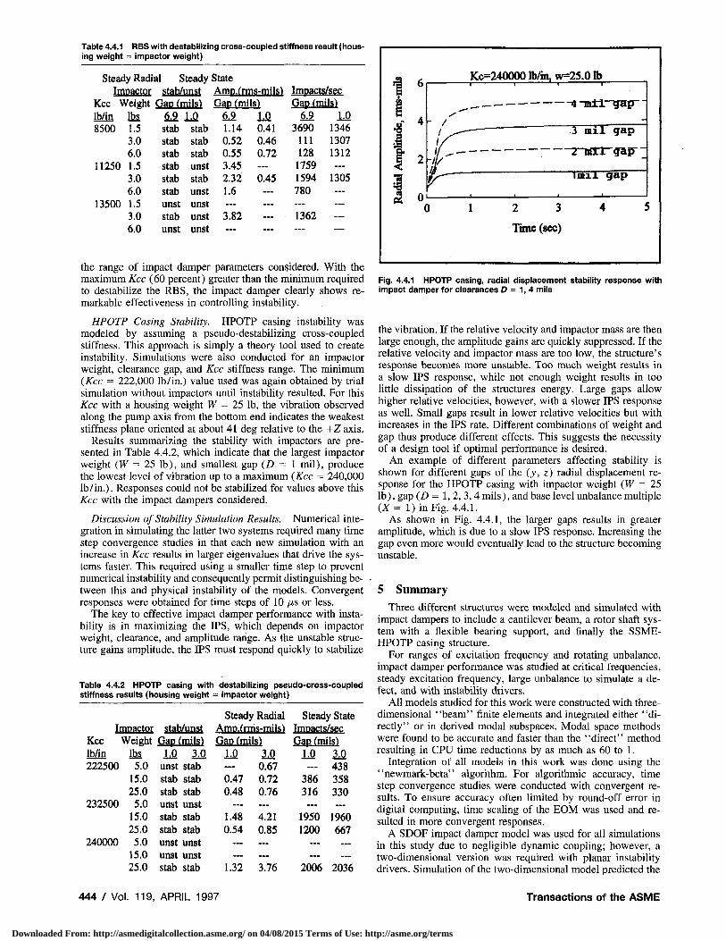
Table 4.4.1 FIBS with destabilizing cross-coupled stiffness result (housing weight = impactor weight)
Steady Radial Steady State Impactor stab/unst AmD.(rms-mils) Impacts/sec
Kcc Weight Gap (mils) Gap (mils) Gap(mijs) lb/in lbs 6.9 LP M LP 42 LP 8500 1.5 stab stab 1.14 0.41 3690 1346
3.0 stab stab 0.52 0.46 111 1307 6.0 stab stab 0.55 0.72 128 1312
11250 1.5 stab unst 3.45 — 1759 — 3.0 stab stab 2.32 0.45 1594 1305 6.0 stab unst 1.6 — 780
13500 1.5 unst unst — — — 3.0 stab unst 3.82 — 1362 — 6.0 unst unst — — —
the range of impact damper parameters considered. With the maximum Kcc (60 percent) greater than the minimum required to destabilize the RBS, the impact damper clearly shows remarkable effectiveness in controlling instability.
HPOTP Casing Stability. HPOTP casing instability was modeled by assuming a pseudo-destabilizing cross-coupled stiffness. This approach is simply a theory tool used to create instability. Simulations were also conducted for an impactor weight, clearance gap, and Kcc stiffness range. The minimum (Kcc = 222,000 lb/in.) value used was again obtained by trial simulation without impactors until instability resulted. For this Kcc with a housing weight W = 25 lb, the vibration observed along the pump axis from the bottom end indicates the weakest stiffness plane oriented at about 41 deg relative to the +Z axis.
Results summarizing the stability with impactors are presented in Table 4.4.2, which indicate that the largest impactor weight (W = 25 lb), and smallest gap (D = 1 mil), produce the lowest level of vibration up to a maximum (Kcc = 240,000 lb/in.). Responses could not be stabilized for values above this Kcc with the impact dampers considered.
Discussion of Stability Simulation Results. Numerical integration in simulating the latter two systems required many time step convergence studies in that each new simulation with an increase in Kcc results in larger eigenvalues that drive the systems faster. This required using a smaller time step to prevent numerical instability and consequently permit distinguishing between this and physical instability of the models. Convergent responses were obtained for time steps of 10 us or less.
The key to effective impact damper performance with instability is in maximizing the IPS, which depends on impactor weight, clearance, and amplitude range. As the unstable structure gains amplitude, the IPS must respond quickly to stabilize
Table 4.4.2 HPOTP casing with destabilizing pseudo-cross-coupled stiffness results (housing weight - impactor weight)
Steady Radial Steady State Impactor stab/unst AmD.(rms-mils) Impacts/sec
Kcc Weieht Gap (mils) Gap (mils) Gao (mils) lb/in lbs LP M LP IQ LP 1Q 222500 5.0 unst stab — 0.67 — 438
15.0 stab stab 0.47 0.72 386 358 25.0 stab stab 0.48 0.76 316 330
232500 5.0 unst unst — — 15.0 stab stab 1.48 4.21 1950 1960 25.0 stab stab 0.54 0.85 1200 667
240000 5.0 unst unst — — — 15.0 unst unst — — — 25.0 stab stab 1.32 3.76 2006 2036
Kc=240000 lb/in, w=2S.O lb
-4 -m±i—gap~
3 mil gap
-2-mtr"gap"
lmxl gap
Fig. 4.4.1 HPOTP casing, radial displacement stability response with impact damper for clearances D = 1, 4 mils
the vibration. If the relative velocity and impactor mass are then large enough, the amplitude gains are quickly suppressed. If the relative velocity and impactor mass are too low, the structure's response becomes more unstable. Too much weight results in a slow IPS response, while not enough weight results in too little dissipation of the structures energy. Large gaps allow higher relative velocities, however, with a slower IPS response as well. Small gaps result in lower relative velocities but with increases in the IPS rate. Different combinations of weight and gap thus produce different effects. This suggests the necessity of a design tool if optimal performance is desired.
An example of different parameters affecting stability is shown for different gaps of the (y, z) radial displacement response for the HPOTP casing with impactor weight (W = 25 lb) ,gap(D = 1, 2, 3,4 mils), and base level unbalance multiple (X = 1) in Fig. 4.4.1.
As shown in Fig. 4.4.1, the larger gaps results in greater amplitude, which is due to a slow IPS response. Increasing the gap even more would eventually lead to the structure becoming unstable.
5 Summary
Three different structures were modeled and simulated with impact dampers to include a cantilever beam, a rotor shaft system with a flexible bearing support, and finally the SSME-HPOTP casing structure.
For ranges of excitation frequency and rotating unbalance, impact damper performance was studied at critical frequencies, steady excitation frequency, large unbalance to simulate a defect, and with instability drivers.
All models studied for this work were constructed with three-dimensional ' 'beam'' finite elements and integrated either ' 'directly" or in derived modal subspaces. Modal space methods were found to be accurate and faster than the "direct" method resulting in CPU time reductions by as much as 60 to 1.
Integration of all models in this work was done using the "newmark-beta" algorithm. For algorithmic accuracy, time step convergence studies were conducted with convergent results. To ensure accuracy often limited by round-off error in digital computing, time scaling of the EOM was used and resulted in more convergent responses.
A SDOF impact damper model was used for all simulations in this study due to negligible dynamic coupling; however, a two-dimensional version was required with planar instability drivers. Simulation of the two-dimensional model predicted the
444 / Vol. 119, APRIL 1997 Transactions of the ASME
Downloaded From: http://asmedigitalcollection.asme.org/ on 04/08/2015 Terms of Use: http://asme.org/terms
individual responses in each orthogonal coordinate of the SDOF model with excellent agreement.
The cantilever beam simulation was conducted to correlate the present study algorithms and impact damper models with those developed in previous research [2] . Free and forced response simulations of the IDC show excellent agreement with former results.
The nature of two resonance peaks on either side of a natural frequency for the structure with impact damper was shown to be the related to the amount of time the impactor undergoes "impact failure" between beat envelope periods.
The experimental RBS with impact damper [2] was modeled and simulated to correlate present study methods with larger DOF systems. The RBS model with 227 DOF, flexible asymmetric bearing supports and impact damper showed remarkable agreement with the experimental frequency response.
The HPOTP casing model frequencies and modes agree well with the model developed at NASA-Marshall. Simulations of the HPOTP with impact damper were conducted with a base level rotor unbalance and multiples thereof for a rotor speed ramp up to 23,000 rpm. Effectiveness of the impact damper was studied at casing criticals, at steady rotor speed, and with high multiples of base level unbalance to simulate defects.
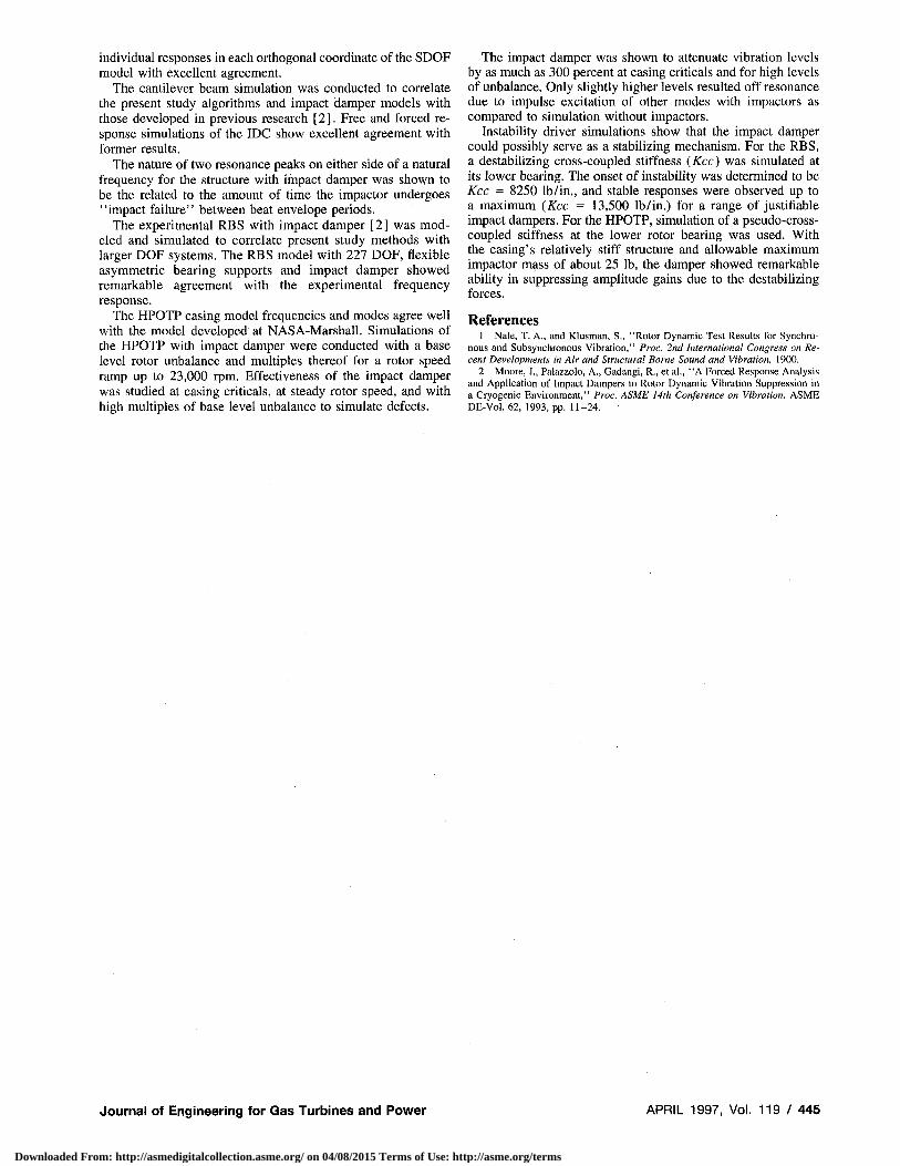
The impact damper was shown to attenuate vibration levels by as much as 300 percent at casing criticals and for high levels of unbalance. Only slightly higher levels resulted off resonance due to impulse excitation of other modes with impactors as compared to simulation without impactors.
Instability driver simulations show that the impact damper could possibly serve as a stabilizing mechanism. For the RBS, a destabilizing cross-coupled stiffness (Kcc) was simulated at its lower bearing. The onset of instability was determined to be Kcc = 8250 lb/in., and stable responses were observed up to a maximum (Kcc = 13,500 lb/in.) for a range of justifiable impact dampers. For the HPOTP, simulation of a pseudo-cross-coupled stiffness at the lower rotor bearing was used. With the casing's relatively stiff structure and allowable maximum impactor mass of about 25 lb, the damper showed remarkable ability in suppressmg amplitude gains due to the destabilizing forces.
References 1 Nale, T. A., and Klusman, S., "Rotor Dynamic Test Results for Synchro
nous and Subsynchronous Vibration," Proc. 2nd International Congress on Recent Developments in Air and Structural Borne Sound and Vibration, 1900.
2 Moore, J., Palazzolo, A., Gadangi, R., et al., "A Forced Response Analysis and Application of Impact Dampers to Rotor Dynamic Vibration Suppression in a Cryogenic Environment," Proc. ASME 14th Conference on Vibration, ASME DE-Vol. 62, 1993, pp. 11-24.
Journal of Engineering for Gas Turbines and Power APRIL 1997, Vol. 1 1 9 / 4 4 5
Downloaded From: http://asmedigitalcollection.asme.org/ on 04/08/2015 Terms of Use: http://asme.org/terms
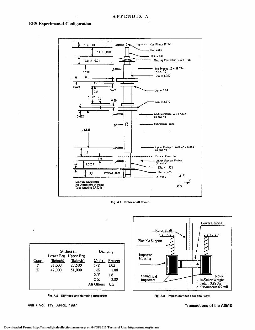
A P P E N D I X A
RBS Experimental Configuration
Drawing noi to scale All Dimensions in inches Total Icnglh is 35.53 in.
Key Phaser Probe
Dia. = 0.5
Dia. = 1.0 Bearing Ccntcrlinc, Z = 31.198
Top Probes . Z = 28.794 (XandY)
Dia.= 1.752
Dia.»3-*»
Dia. =4.872
Middle Probes, Z = 17.137 (XandY)
Calibraiiun Probe
Upper Damper ProbcsZ • 6.862 (XandY)
Damper Ccntcrlinc Lower Damper Probes (X and Y)
Dia. = 1.552
Dia. = 3.00
Z =0.0 4 z
Fig. A.1 Rotor shaft layout
Stiffness Lower Brg Upper Brg
Damping
Coord (lb/inchl fib/inch) Mode Percent Y 32,000 27,500 1-Y 1.05 Z 42,000 51,000 1-Z 1.88
2-Y 1.6 2-Z 2.88
All Others 0.5
Fig. A.2 Stiffness and damping properties
446 / Vol. 119, APRIL 1997
1. Impactor Weight Total: 3.88 lbs
2. Clearances: 6.9 mil
Fig. A.3 Impact damper sectional view
Transactions of the ASME
Downloaded From: http://asmedigitalcollection.asme.org/ on 04/08/2015 Terms of Use: http://asme.org/terms