Embed Size (px)
Citation preview

271
Modeling and Simulation Fundamentals: Theoretical Underpinnings and Practical Domains, Edited by John A. Sokolowski and Catherine M. BanksCopyright © 2010 John Wiley & Sons, Inc.
9
MODELING HUMAN BEHAVIOR
Yiannis Papelis and Poornima Madhavan
Human behavior is the collective set of actions exhibited by human beings, either individually or in groups of various sizes and compositions. Modeling human behavior is an interdisciplinary fi eld that aims at developing models that refl ect or even replicate reality, given a set of appropriate initial condi-tions. The fi eld is quickly gaining momentum and has wide ranging and diverse applications in civilian and military domains. Because of the widespread uti-lization of human behavior models, it is important to have a fi rm grasp on the theoretical underpinnings of the fi eld and what such models can provide; it is also important to recognize the associated limitations. As human beings, we are familiar with our own and others ’ behavior and tend to confuse this famil-iarity with a reliable and generalizable scientifi c process. We are also accus-tomed to the predictive power of physics - based models and tend to presume that human behavior models possess similar abilities of predicting behavior, something that is rarely true [1] . It is thus important to realize the nature of the complexity of human behavior and try to address it when developing analytic models.
The issues that affect human behavior modeling vary greatly depending on the level of required behaviors and the overall size of the population being modeled. At the physical level , human behavior is driven by physiology and

272 MODELING HUMAN BEHAVIOR
automated processes, whereas at the tactical level , decision making and emo-tions are the primary drivers for our short - term actions. At the highest level, strategic behaviors involve longer planning and complex decision making according to intuition, emotions, and experience. At the same time, there are signifi cant differences between modeling individuals or groups and even further differences that depend on the size of the group that is modeled. It is thus benefi cial to defi ne a taxonomy within which to classify behavioral model-ing approaches and identify related challenges. Tables 9.1 and 9.2 present a classifi cation of human behavior modeling organized according to the level of cognitive processing involved in the behavior as well as the size of the popula-tion being modeled, along with examples.
The issues associated with each classifi cation vary greatly, as is the maturity of the related research. For example, models at the physical level are based on empirical research that can often be validated and thus have predictive value. Similarly, individual - based models are typically less challenging than group - or society - level models because of the complexity introduced by the interactions among individuals and the chaotic nature of evolutionary behav-
Table 9.1 Human behavior modeling issues
Individual Group Society
Strategic High - level decision making based on intuition and emotion
Interaction dominant models, collective intelligence
Changes to culture, political situations
Tactical Concrete decision making; short - term emotions affect decisions
Social infl uence, emotional refl ection, collaboration
Communication - dominant models
Physical Reactive models based on stimulus – response, physiology, motor skills
Physics - based interactions
Population dynamics
Table 9.2 Example applications
Individual Group Society
Strategic Persistent virtual reality characters
Economics models, fi nancial markets
Insurgency modeling, effect of sanctions
Tactical Route selection; obstacle avoidance; procedural tasks
Crowd behaviors, traffi c simulation, war games, computer - generated teams
Public opinion polling, consumer models, social simulation
Physical Reaction time, skills assessment
Crowd movement simulation
Disease spreading, population aging

BEHAVIORAL MODELING AT THE PHYSICAL LEVEL 273
iors. On the other hand, tactical and strategic behaviors are harder to model due to the adaptive and unpredictable nature of human behavior. When incor-porating larger populations, the complexity drastically increases to the point where such models are diffi cult, if not impossible to validate. It is interesting to note that despite these apparent limitations, such models are in widespread use in both civilian and military applications. The reasons for this popularity are many. The output of such models is easy to understand because simula-tions using such models often resemble real life. When presented through means that obscure the source of the results, it is often impossible to differ-entiate simulation from real life. For example, results of military simulations presented with the same tools used during actual operations obscure the source of the displayed data. Another reason for the popularity of tactical models is the ability to change input parameters and rerun the simulation obtaining a new answer for the what - if scenario. Iterative use of models in such a manner supports exploratory analysis that helps us gain an intuitive feel for the modeled situation. And even though such models elude validation on a strictly scientifi c basis, it is often possible to perform sensitivity analysis and identify broad trends as opposed to exact predictions. For example, a war - gaming simulation may help a planner realize that increasing the number of armored vehicles has a positive effect on the outcome of a scenario, but it cannot pinpoint the exact number of vehicles required to win the battle with a certain probability. By simulating models of human behavior, we seek to understand, not necessarily predict, the aggregate behavior of an inherently complex system for which we have no better model.
In summary, the issues and techniques used for implementing human behavior models vary greatly depending on the scope and size of population, and it is thus important to put each approach in the appropriate context. The remainder of this module summarizes material in the context of the taxonomy illustrated in Tables 9.1 and 9.2 .
BEHAVIORAL MODELING AT THE PHYSICAL LEVEL
The physical level of behavior provides the most opportunity for modeling using strict scientifi c and engineering approaches. By assuming simple and constant motivation functions, such as “ seeking to a goal, ” “ avoiding an obsta-cle, ” “ operating a vessel, ” or “ tracking a lane, ” models can predict measurable actions that are primarily physical in nature and depend on physiological or psychological principles [2] . Decisions are done at an instinctive or reactive level, and emotions have little impact on the process; instead, performance is governed by the level of workload, fatigue, situational awareness, and other similar factors. Some modeling efforts treat a human being as a limited capac-ity processor that can selectively parallel process but with specifi c penalties for splitting attention among many tasks [3] . Based on such assumptions, models can use laws of physics, experimental data, or other “ hard ” facts about

274 MODELING HUMAN BEHAVIOR
human performance that yield predictive operational models of human behav-ior [4] . On a more practical basis, fuzzy logic is often used to simulate human control tasks. Fuzzy logic is a theory of developing controllers that utilize fuzzy variables, a concept derived from fuzzy sets [5,6] . A fuzzy variable takes on approximate as opposed to exact values; for example, when driving a vehicle, we may refer to the speed as fast or slow, in lieu of an exact number, that is, 53.5 mph. Even though fuzzy logic is often used as a means to obtaining better control (e.g., in a thermostat), it provides a good basis for mimicking human physical behavior because it simulates our perception of the world, which is approximate and not exact. As a contrast to that approach, it is also possible to build traditional control systems that simulate human control tasks, as shown by Gabay and others who developed an experimental approach to obtaining parameters for a traditional control system that mimics the perfor-mance of a human being in closed - loop tracking tasks [7] . Similar models exist that predict human performance while operating a vehicle, piloting a plane, or performing general tasks.
BEHAVIORAL MODELING AT THE TACTICAL AND STRATEGIC LEVEL
The tactical level of behavior modeling focuses on human behavior when seeking short - term goals. The difference between physical and higher behav-ior levels is rooted in the complexity of the goal and duration of the activity being modeled. Whereas physical behavior models assume singular and/or simple goals and focus on human capabilities, higher - level behaviors have more complicated goals that take longer to achieve and involve decision making at various levels. For example, consider the task of driving. At the physical level, one would model the ability of a driver to track the lane of a road. At the tactical level, however, one would model a passing maneuver or a lane change, including the decision making involved in selecting the particu-lar maneuver. Furthermore, a strategic level of behavior would focus on route selection, or even the choice between driving versus taking an alternative means of transport.
When modeling higher - level behaviors, there are two broad schools of thought. One considers human beings as rational operators that attempt to maximize a utility function or achieve a specifi c goal. Such models ignore the effect of emotion and instead concentrate on rational decision making using deterministic or stochastic approaches. The second school of thought consid-ers human beings as quasi - rational entities that still pursue a specifi c utility function, but frequently make suboptimal decisions and exhibit actions that can act contrary to their stated goals and can even reach the level of self - destructive behavior [8,9] .
Rational decision making is by far easier to model and simulate than quasi - rational behavior. Behaviors stemming from rational thought are by their nature algorithmic and procedural and often represent skills for which humans

BEHAVIORAL MODELING AT THE TACTICAL AND STRATEGIC LEVEL 275
train, that is, driving an automobile, fl ying a plane, being a soldier, being a participant in a team sport, and so on. Techniques for developing such models include state machines, rule - based systems (RBSs), and pattern recognition, among others. Modifi cations that add stochastic variation to behavior can be blended into the baseline approaches and because such variation is not driven by emotions, traditional statistical approaches can be used to enhance and fi ne - tune rational decision models. It is also possible to incorporate limits that refl ect how excessive demands may stress human mental and physical capabili-ties, effectively blending the physical and tactical levels of behavior into a singular model. The inclusion of physics - or psychology - based perception models can further enhance the overall behavior model by reducing the quality of data used for decision making. More advanced models utilize processes that attempt to simulate experience and intuition. Intuition in particular, which refers to the ability of a human being of recognizing something without a full understanding of how this recognition takes place, is a key characteristic of strategic decision making. Research has shown that such decision making is rooted in pattern matching based on prior knowledge, as a result, technical approaches to construct models that exhibit strategic decision making depend on knowledge databases, pattern matching using neural networks, hidden Markov models (HMMs), and similar techniques [10] .
Quasi - rational behavior models are more challenging to develop. The pro-cesses that govern suboptimal decision making are an active topic of research and not yet fully understood. Such processes are complex and depend on a variety of current and expected outcome emotions, and on the context within which choices are made [8,11,12] . Lacking strict constraints that are based on optimizing functions, it is tempting to substitute stochastic decision making as a means to simulate quasi - rational behavior. However, suboptimal decisions are not random decisions; it is just that they are governed by processes that we do not yet fully understand and thus cannot model on a fi rst - principle basis. Suboptimal decisions are also not intuitive decisions; in fact, as discussed earlier, it has been shown that intuitive behavior is rooted in fact - based experi-ence and pattern matching. Nevertheless, it is possible to develop models that capture some of the better understood factors involved in quasi - rational behavior. For example, we can use models that simulate emotional state, with actions being a side effect or result of the current emotional state [13] . By simulating emotions and letting the emotional state control the actions exhib-ited by the model, behavior is by defi nition suboptimal as it is detached from goal seeking, yet driven by processes that conform to reality. In general, for models requiring fi delity at strategic levels of behavior, the challenge lies in simulating irrationality and other abstract and suboptimal decision - making processes that are not strictly driven by goal - seeking human behavior traits.
Lumped versus Distributed Models
The issues that differentiate the physical, tactical, and strategic behavior models are further amplifi ed when considering the incorporation of multiple

276 MODELING HUMAN BEHAVIOR
entities into the simulation. The treatment so far has concentrated on models of an individual human; we now look at the issues involved when modeling multiple humans.
First, let us defi ne the difference between lumped and distributed models in human behavioral modeling. The notion of a lumped model originates in electrical engineering and refers to studying a circuit assuming that each element is an infi nitesimal point in space and all connections are perfect, thus their effect on the circuit need not be considered. The assumption here is that the effects of the connections are either small, or are taken into account in the element model. Lumped systems are typically modeled by using differen-tial equations. In human behavior modeling, a lumped model is one that treats modeling of multiple entities as a unifi ed model that ignores the specifi c inter-actions, or presumes that such interactions are factored into the singular model. As in other disciplines, such models typically involve differential equa-tions that represent the change of system variables over time. Examples include population dynamics and disease spreading [14,15] . Lumped system models are powerful when considering that they operate independently of the size of the population they model. At the same time, their weakness lies in assumption that interpopulation interactions are captured by the basic model, something that is not always the case. In fact, lumped models of human behav-ior implicitly presume that motivation and thus behavior remain largely con-stant. For example, consider the limited capacity population equation developed by the eighteenth century mathematician Verhulst [16] :
p r p
K pK
t tt
+ = ⋅−
1 .
The equation provides a model that predicts the size of the population at a particular time ( p t +1 ) given the population at a prior time ( p t ), the growth rate ( r ), and the maximum population size ( K ). Note that numerous factors such as reproductive choice, socioeconomic prosperity, state of medical care, and so on, are implicitly factored into the growth rate, thus making this a lumped model.
Let us contrast this with a distributed system. Much like lumped systems, the notion of a distributed system originates in engineering, where systems are represented by taking into account variations of elements not only over time but over other variables; in the case of electrical engineering, connections are imperfect having fi nite impedances; in the case of mechanical engineering, the twist of a rod or link along its length is not lumped into the model; instead, it is taken into account explicitly. In basic engineering modeling, distributed systems utilize partial differential equations to capture changes over time as well as changes over spatial variables. In human behavior modeling, one can approach distributed system modeling in two ways. One is by subscribing to Nagel ’ s reductionism theory , which states that one way to understand the behavior of multiple entities is to understand a single entity and then coalesce

TECHNIQUES FOR HUMAN BEHAVIOR MODELING 277
that knowledge predicting the behavior of multiple entities [17] . Nagel pro-posed this theory to suggest that a generalized approach to science can be achieved by reducing complex theories into more fundamental theories, pro-vided that there are explicit linkages between the two theories that allow us to transition the knowledge from the reduced to the more complex one.
This approach is parallel to augmenting the basic equations governing the aggregate behavior of a population with additional factors, constructing complex models by combining simpler ones. Surely, use of partial differential equations can be construed as one way to achieve this, as is the use of ad hoc modeling equations that incorporate additional factors into the model. Another school of thought, which contradicts Nagel ’ s reductionism theory, is that superposition of behaviors is not adequate; instead, the interactions among entities themselves create fundamentally new rules and laws that apply to the aggregate behavior of the group and such laws do not exist when dealing with a single entity. As stated in Artifi cial Intelligence , “ Often the most effi cient way to predict and understand the behavior of a novel complex system is to construct the system and observe it ” [18] . By using agent - based modeling, a topic that is covered in Chapters 1 and 8 in this book, we can address the limi-tations of lumped models in human behavior simulation and study the effect of individual behavioral models on the evolutionary behavior of populations of varying size. Of course, agent - based modeling can become computationally expensive as the size of the population grows. For studying phenomena that depend on population sizes that exceed current computing capacity, lumped models may be the only practical approach. It is important to note that the taxonomy presented in Table 9.1 differentiates between group - level and soci-ety - level modeling, that is, a refl ection of practical limitations that make lumped system models the only viable alternative for simulating entities whose size approaches whole societies (i.e., millions of entities or more). It is conceiv-able that computational advances in the near future will support practical agent - based modeling or arbitrarily large populations, fusing the group - and society - level classifi cations.
The remainder of the chapter summarizes various techniques utilized in building human behavior models. These techniques apply to individual or multiagent simulations.
TECHNIQUES FOR HUMAN BEHAVIOR MODELING
Fuzzy Logic Control
As indicated earlier, the use of fuzzy logic is targeted primarily at building controllers that can better handle control tasks for which traditional control approaches fail. This typically occurs in nonlinear or adaptive systems, which, due to their dynamic nature, violate the assumptions of linearity on which classical control approaches depend. Fuzzy logic controllers on the other hand, respond better to such systems because they mimic human adaptability
278 MODELING HUMAN BEHAVIOR
associated with control tasks. Fuzzy controllers depend on fuzzy logic, which in turn is based on multivalued logic supporting variables that can take values between conventional evaluations. For example, consider a binary variable representing “ yes ” or “ no ” ; it can have only two valuations 0 and 1 (or any other pairs of numbers); however, there is no way to represent “ maybe. ” A fuzzy variable on the other hand, can have any value between “ yes ” and “ no, ” including “ maybe, ” “ possibly, ” “ not likely, ” and so on. The ability to classify variables in humanlike terms is benefi cial, if for no other reason for it makes sense. For example, if one is asked the question: “ What is the room tempera-ture, ” the most typical answers are qualitative; for example, one may answer: “ It is fi ne, ” or “ it is cold ” or “ it is pretty hot ” ; rarely does one reply by stating: “ The temperature is 79.4 degrees Fahrenheit. ” If our goal is to build a tem-perature controller that acts humanlike, then using fuzzy variables provides a natural way to deal with valuations that conform to human interpretation. At the same time, using such variables provides little value unless a corresponding theory allows manipulation and effective use of such variables when solving a problem. It is the development of the theory of fuzzy sets [5] that provided the mathematical tools necessary to handle fuzzy variables and operationalize control strategies, and in turn can facilitate modeling human behavior.
In the same way that traditional set theory defi nes set operations (union, difference, etc.), fuzzy set theory provides associated operators that allow computer manipulation of fuzzy variables. Fuzzy logic makes it possible to create mathematical formulations that allow computer - based handling of humanlike interpretations of the world, and as such, provides a fundamental tool for building control systems that simulate human behavior at the physical (or control) level.
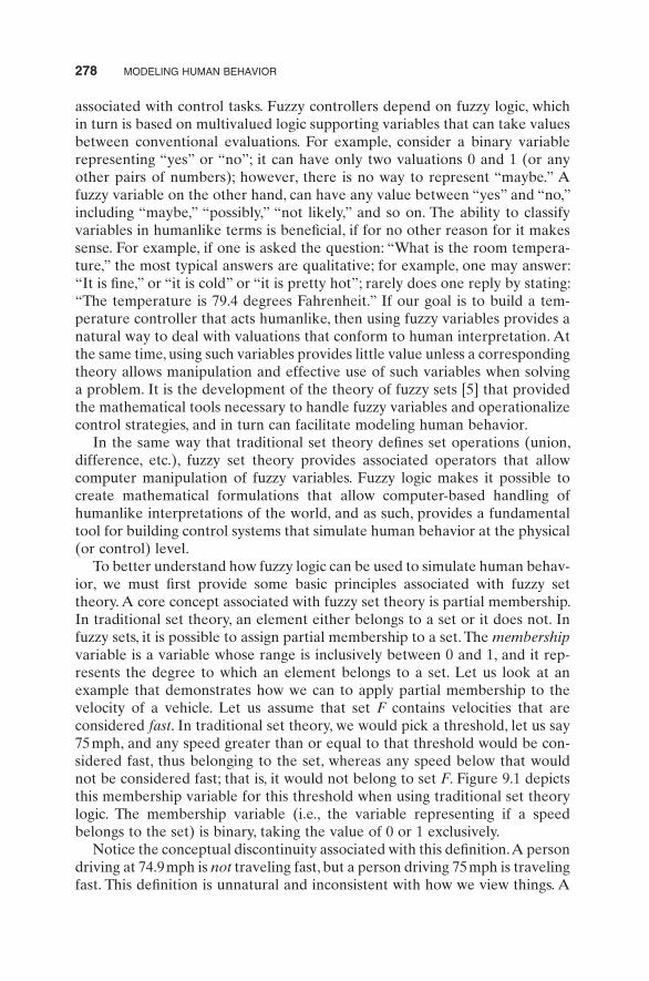
To better understand how fuzzy logic can be used to simulate human behav-ior, we must fi rst provide some basic principles associated with fuzzy set theory. A core concept associated with fuzzy set theory is partial membership. In traditional set theory, an element either belongs to a set or it does not. In fuzzy sets, it is possible to assign partial membership to a set. The membership variable is a variable whose range is inclusively between 0 and 1, and it rep-resents the degree to which an element belongs to a set. Let us look at an example that demonstrates how we can to apply partial membership to the velocity of a vehicle. Let us assume that set F contains velocities that are considered fast . In traditional set theory, we would pick a threshold, let us say 75 mph, and any speed greater than or equal to that threshold would be con-sidered fast, thus belonging to the set, whereas any speed below that would not be considered fast; that is, it would not belong to set F . Figure 9.1 depicts this membership variable for this threshold when using traditional set theory logic. The membership variable (i.e., the variable representing if a speed belongs to the set) is binary, taking the value of 0 or 1 exclusively.
Notice the conceptual discontinuity associated with this defi nition. A person driving at 74.9 mph is not traveling fast, but a person driving 75 mph is traveling fast. This defi nition is unnatural and inconsistent with how we view things. A

TECHNIQUES FOR HUMAN BEHAVIOR MODELING 279
more natural way to classify speed is to provide a transition range, let us say starting at 70 mph and ending at 80 mph. A person driving below 70 is surely not going fast, and a person driving above 80 is defi nitely going fast. Any speed between 70 and 80 would be considered borderline, with an ever - increasing bias toward fast as we approach the upper end of the range; in fuzzy set nomenclature, as the speed approaches 80 mph, the membership to the set of driving fast will also increase. Figure 9.2 depicts the fuzzy set membership based on this defi nition.
Note that the membership to the “ fast ” set now varies between 0 and 1; for example, when driving 73 mph, the membership variable would be 0.3.
The basic operations applied to traditional sets can also be applied to fuzzy sets. Consider two sets whose membership profi les are shown in Figure 9.3 ; set A represents velocities that are “ about the speed limit ” and set B repre-sents velocities that are “ safe, ” defi ned as more than about 60 and less than about 75.
The intersection of these sets is any velocity that complies with membership to set A and set B. The union of these sets is any velocity that complies with membership to set A or set B. The membership function for the intersection and union of these sets is shown in dashes in Figure 9.4 . Similarly, it is possible to defi ne set subtraction and set negation.
Having established the basic tools associated with the fuzzy set theory, let us now see how we can model a controller using fuzzy logic. Our goal is to
Membership
Velocity75 mph
0
1
Figure 9.1 Binary set membership.
Membership
Velocity70 mph
0
1
80 mph
Figure 9.2 Fuzzy set membership.

280 MODELING HUMAN BEHAVIOR
simulate how a human would control the environment in order to achieve a goal. We represent this effort as a set of rules, written as if - then statements and using qualitative descriptions both for the observations of the environ-ment but also for the actions that need to be taken to maintain the desired control. In fuzzy logic nomenclature, these rules are referred to as the linguis-tic rules . Let us use a simple example to demonstrate the process. The example is of a driver controlling the speed of a vehicle to maintain a safe and legal speed, provided the speed limit is 65 mph. In order to apply fuzzy logic, we must fi rst identify the variables that will be observed and the qualitative assess-ment of these variables. Then, we need to defi ne the control actions, again using fuzzy terms, and fi nally we must provide the linguistic rules.
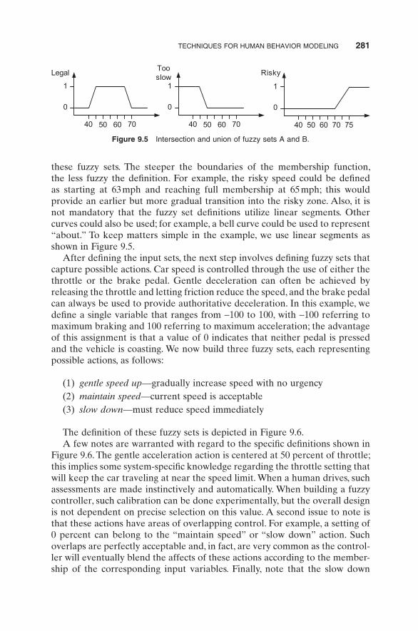
The variable to be controlled is the speed of our vehicle, and we create three rough assessments (fuzzy sets) of the speed, as follows:
(1) legal speed — from about 45 mph to about 65 mph (2) too slow — any speed below about 45 mph (3) risky — any speed above about 70 mph
Note that even though these defi nitions mention specifi c values for the velocity, terms such as “ about ” create a qualitative or fuzzy defi nition. Figure 9.5 depicts one possible defi nition of the three fuzzy sets mentioned above. The controller designer has a choice on how to operationalize the defi nition of “ about ” by appropriately shaping the membership functions for each of
Velocity72
0
1
Velocity60
0
1
Set AAbout 75
Set BSafe
7578 58 77
Figure 9.3 Example of fuzzy sets.
777858 60 75
0
1
7277
7858 60 75
0
1
72
A and B A or B
Figure 9.4 Intersection and union of fuzzy sets A and B.
TECHNIQUES FOR HUMAN BEHAVIOR MODELING 281
these fuzzy sets. The steeper the boundaries of the membership function, the less fuzzy the defi nition. For example, the risky speed could be defi ned as starting at 63 mph and reaching full membership at 65 mph; this would provide an earlier but more gradual transition into the risky zone. Also, it is not mandatory that the fuzzy set defi nitions utilize linear segments. Other curves could also be used; for example, a bell curve could be used to represent “ about. ” To keep matters simple in the example, we use linear segments as shown in Figure 9.5 .
After defi ning the input sets, the next step involves defi ning fuzzy sets that capture possible actions. Car speed is controlled through the use of either the throttle or the brake pedal. Gentle deceleration can often be achieved by releasing the throttle and letting friction reduce the speed, and the brake pedal can always be used to provide authoritative deceleration. In this example, we defi ne a single variable that ranges from − 100 to 100, with − 100 referring to maximum braking and 100 referring to maximum acceleration; the advantage of this assignment is that a value of 0 indicates that neither pedal is pressed and the vehicle is coasting. We now build three fuzzy sets, each representing possible actions, as follows:
(1) gentle speed up — gradually increase speed with no urgency (2) maintain speed — current speed is acceptable (3) slow down — must reduce speed immediately
The defi nition of these fuzzy sets is depicted in Figure 9.6 . A few notes are warranted with regard to the specifi c defi nitions shown in
Figure 9.6 . The gentle acceleration action is centered at 50 percent of throttle; this implies some system - specifi c knowledge regarding the throttle setting that will keep the car traveling at near the speed limit. When a human drives, such assessments are made instinctively and automatically. When building a fuzzy controller, such calibration can be done experimentally, but the overall design is not dependent on precise selection on this value. A second issue to note is that these actions have areas of overlapping control. For example, a setting of 0 percent can belong to the “ maintain speed ” or “ slow down ” action. Such overlaps are perfectly acceptable and, in fact, are very common as the control-ler will eventually blend the affects of these actions according to the member-ship of the corresponding input variables. Finally, note that the slow down
40 50
0
1
Legal
60 70 40 50
0
1
Tooslow
60 70 40 50
0
1
Risky
60 70 75
Figure 9.5 Intersection and union of fuzzy sets A and B.

282 MODELING HUMAN BEHAVIOR
action uses a more complicated shape than the triangles used for the other two actions. As mentioned earlier, the selection of the particular shape should depend on the associated meaning of the action and is not constrained in any particular shape. In this case, the sharp rise on the right side implies that even though small throttle inputs can be considered part of the “ slow down ” set, the proportional membership value is very small compared with applying the brake pedal.
The fi nal step in the defi nition of the fuzzy control algorithm involves the linguistic rules. We will use three rules as follows:
• Rule 1: If speed is legal, then maintain speed. • Rule 2: If speed is too slow, then gently speed up. • Rule 3: If speed is risky, then slow down.
Few simple rules are used here in order to keep the example manageable. Additional variables could be defi ned (e.g., another variable may be the current acceleration) and rules involving arbitrary predicates can be used; for example, a more complicated rule could be: “ If speed is risky and acceleration is positive, then decelerate briskly. ” Once the implementation has been auto-mated, adding new rules and variables can be done with relative ease as their treatment is uniform.
At a conceptual level, simulating human control behavior using fuzzy logic is done by using a measured value of each fuzzy variable, determining the fuzzy sets to which the actual value belongs, and then determining which actions are affected by these “ active ” fuzzy sets. This process was outlined in Mamdani and Assilian [19] . Actions that contain active sets in their predicate are referred to as “ fi ring. ” Once the fi ring actions have been identifi ed, their contribution to the eventual control input is calculated according to the degree of membership that each rule provides. One way to visually explain this process is by creating a “ rules chart, ” which on the horizontal axis contains the input fuzzy sets and on the vertical axis contains the action fuzzy sets. The rules chart for our example system is shown in Figure 9.7 , which uses different line styles to separate among the input and action fuzzy sets. Also, vertical lines have been drawn to show the ranges of each input fuzzy set, and hori-
0% Brakeand throttle
0
1
Gentleaccel
100%Brake
100%Throttle
0% Brakeand throttle
100%Brake
100%Throttle
0% Brakeand throttle
100%Brake
100%Throttle
0
1
0
1
5% 45%25% 75% 15%–100%
–25% 0%0%50%
Maintainspeed
Slowdown
Figure 9.6 Fuzzy sets for possible actions.

TECHNIQUES FOR HUMAN BEHAVIOR MODELING 283
zontal lines have been drawn to show the application area of each action. Note that each input fuzzy set creates a horizontal region; in this case, the “ too slow ” input covers any speed below 50 mph, the “ legal ” input covers the region from 40 to 70 mph, and fi nally the “ risky ” input covers any speed over 65 mph.
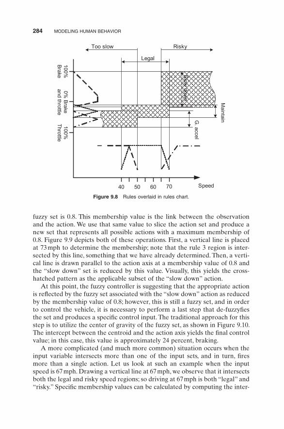
Given the rules chart, the mapping between variables and rules can be interpreted as the rectangular region that overlaps the input range and the corresponding rule range. Figure 9.8 illustrates these three regions, one per rule. The upper - right region represents rule 3, the middle region represents rule 2, and the lower - left region represents rule 1. Note that rules overlap, indicating that there are situations where a given speed may belong to more than one input set. Correspondingly, more than one of the rules will fi re in order to produce the fi nal action, which will consist of a blend of each of the actions associated with the fi ring rules.
Let us now look more specifi cally at how the controller works by assuming that the current speed of the car is 73 mph. This speed can only belong to the “ risky ” input set, so the only rule that can fi re is rule 3. We determine this by observing that this is the only rule that references the “ risky ” input in its predicate. If additional rules referenced the risky group, they would also fi re. Next, we determine the degree of membership of this value to the “ risky ” set. Given the visual defi nition of the fuzzy sets, calculating the membership value can be done by inspecting the rightmost shape of Figure 9.5 , but of course, it can also be programmed on a digital computer. In this case, by inspection, we determine that the value of membership of the 73 - mph speed to the risky
40 50 60 70
Legal
RiskyToo slow
Slow
down
MaintainG
. accel
Legal
Risky
Too slow
Slow down
Gentle accel
Maintain
Speed
0% B
rakeand throttle
100%B
rake100%
Throttle
Figure 9.7 Rules chart for fuzzy controller example.
284 MODELING HUMAN BEHAVIOR
fuzzy set is 0.8. This membership value is the link between the observation and the action. We use that same value to slice the action set and produce a new set that represents all possible actions with a maximum membership of 0.8. Figure 9.9 depicts both of these operations. First, a vertical line is placed at 73 mph to determine the membership; note that the rule 3 region is inter-sected by this line, something that we have already determined. Then, a verti-cal line is drawn parallel to the action axis at a membership value of 0.8 and the “ slow down ” set is reduced by this value. Visually, this yields the cross-hatched pattern as the applicable subset of the “ slow down ” action.
At this point, the fuzzy controller is suggesting that the appropriate action is refl ected by the fuzzy set associated with the “ slow down ” action as reduced by the membership value of 0.8; however, this is still a fuzzy set, and in order to control the vehicle, it is necessary to perform a last step that de - fuzzyfi es the set and produces a specifi c control input. The traditional approach for this step is to utilize the center of gravity of the fuzzy set, as shown in Figure 9.10 . The intercept between the centroid and the action axis yields the fi nal control value; in this case, this value is approximately 24 percent, braking.
A more complicated (and much more common) situation occurs when the input variable intersects more than one of the input sets, and in turn, fi res more than a single action. Let us look at such an example when the input speed is 67 mph. Drawing a vertical line at 67 mph, we observe that it intersects both the legal and risky speed regions; so driving at 67 mph is both “ legal ” and “ risky. ” Specifi c membership values can be calculated by computing the inter-
40 50 60 70
Legal
RiskyToo slow
Slow
down
Speed
0% B
rakeand throttle
100%B
rake100%
Throttle
MaintainG
. accel
Figure 9.8 Rules overlaid in rules chart.

TECHNIQUES FOR HUMAN BEHAVIOR MODELING 285
cept between the 67 - mph line and the membership profi le functions. Figure 9.11 depicts the intercepts, which occur at 0.2 for the risky set and 0.4 for the legal set. To determine which rules fi re, we can either inspect the rules and identify the ones that include the risky or legal sets in their predicate or graphi-cally identify which region the 67 - mph line intersects in the rules chart shown in Figure 9.9 . Both approaches yield rule 1 and rule 3 as the rules that fi re in this situation. To determine the value applied to the slicing of each of the actions, we select the membership value of legal for the maintain speed action (in this case a value of 0.4) and the membership value of risky for the slow down action (in this case a value of 0.2).
Figure 9.12 illustrates the appropriate regions and the application of the membership values to the two fi ring actions. The resultant action sets are shown on the right side of the fi gure. As in the previous example, the fi nal
40 50 60 70
Actual speed = 73 mph
Membership value = 0.8
0
1
100%T
hrottle0%
Brake
and throttle100%B
rake
10
0.8
0.8
Firing rule
Figure 9.9 Rules overlaid in rules chart.
100%Brake 0% Brake and
throttleFinal control
value
Figure 9.10 Final control value.

286 MODELING HUMAN BEHAVIOR
control output can be derived by selecting the centroid of the union of the fuzzy action sets. In this case, this value indicates a slight application of the brake, which is consistent with the earlier solution that demanded larger brake application due to the higher speed.
As demonstrated by the above examples, fuzzy logic can be used to build controllers that mimic the operation of human beings including the interpreta-tion of input data, specifi cation of linguistic rules that select control actions, and correlation of action intensity with root cause of the disturbance. This last feature is a critical component of fuzzy logic control. Whereas classical control approaches utilize differential equations to develop control commands that depend on specifi c assumptions about the system under control, fuzzy logic controllers utilize an arbitrary number of linguistic rules, each of which can handle a portion of the controlled system ’ s performance envelope. This resem-bles low - level human behavior; we can easily switch between control strategies and manage to adapt along with a system, hence, the attractiveness of fuzzy logic for building humanlike control algorithms. Finally, note that even though
Risky
Legal
Speed40 50 60 70 75
Speed = 67
0.2
0.4
Figure 9.11 Input intercepts for the second example.
0% B
rakeand throttle
100%B
rake
Risky
Legal
Speed40 50 60 70 75
Speed = 67
0.2
0.4
Maintain0.4
Slow down0.2
Final control value
0% Brake and throttle
100%Brake
Figure 9.12 Rules chart illustrating controller operation.

TECHNIQUES FOR HUMAN BEHAVIOR MODELING 287
Follow
Pull-out Accelerate
Pull-in ahead
Done
DeceleratePull-in behind
the examples shown here focus on the low - level control, it is possible to apply fuzzy logic in higher - level decision - making processes; in fact, any area that can be defi ned in terms of fuzzy sets and formulated as a closed - loop control problem described by linguisitc rules can benefi t from the direct or indirect application of fuzzy logic theory.
Finite - State Machines ( FSM s )
Another very popular technique used for building human behavior models is FSMs. A state machine consists of a set of states, a set of transitions among these states, and a set of actions. Actions are associated with states and along with transitions govern the behavior of the modeled entity. Each state and associated actions represent a distinct behavior phase that the entity can exhibit. The transitions control when the mode of operation changes based on external factors. Sometimes, a set of initialization and termination functions are associated with each state; the initialization function executes once when a state fi rst takes control, and the termination function executes once when a state losses control.
The use of FSMs for modeling human behavior is better explained by con-structing an example. In this case, we will use the example of the behavior of a driver that is attempting to pass the vehicle ahead while driving along a two - lane road and each lane having opposite direction. For state machines with relatively few states, a directed graph can be used to depict the structure of the state machine, so we will use this technique here. Figure 9.13 illustrates a directed graph representing the behavior.
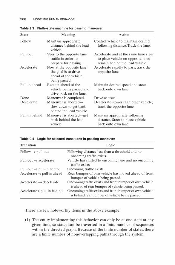
There are seven states and eight transitions. Table 9.3 contains the meaning of each state along with the actions associated with each state.
Transitions control when the entity will change from one state to the other. Depending on the exact formalism used, transitions can be associated with the occurrence of singular external events or can contain complex logic for deter-mining when states change. In the model described, transitions are generalized Boolean functions that can contain arbitrarily complex logic that eventually evaluates to true or false. Table 9.4 contains a sample of transitions and their associated logic as would apply to this example.
Figure 9.13 Directed graph representing passing state machine.
288 MODELING HUMAN BEHAVIOR
Table 9.3 Finite - state machine for passing maneuver
State Meaning Action
Follow Maintain appropriate distance behind the lead vehicle.
Control vehicle to maintain desired following distance. Track the lane.
Pull - out Veer to the opposite lane traffi c in order to prepare for passing.
Accelerate and at the same time steer to place vehicle on opposite lane; remain behind the lead vehicle.
Accelerate Now at the opposite lane; the goal is to drive ahead of the vehicle being passed.
Accelerate rapidly to pass; track the opposite lane.
Pull - in ahead Remain ahead of the vehicle being passed and drive back on the lane.
Maintain desired speed and steer back onto own lane.
Done Maneuver is completed. Drive as usual. Decelerate Maneuver is aborted – –
slow down to get back behind the lead vehicle.
Decelerate slower than other vehicle; track the opposite lane.
Pull - in behind Maneuver is aborted – – get back behind the lead vehicle.
Maintain appropriate following distance. Steer to place vehicle back onto own lane.
Table 9.4 Logic for selected transitions in passing maneuver
Transition Logic
Follow → pull - out Following distance less than a threshold and no oncoming traffi c exists.
Pull - out → accelerate Vehicle has shifted to oncoming lane and no oncoming traffi c exists.
Pull - out → pull - in behind Oncoming traffi c exists. Accelerate → pull - in ahead Rear bumper of own vehicle has moved ahead of front
bumper of vehicle being passed. Accelerate → decelerate Oncoming traffi c exists and front bumper of own vehicle
is ahead of rear bumper of vehicle being passed. Accelerate ( pull - in behind Oncoming traffi c exists and front bumper of own vehicle
is behind rear bumper of vehicle being passed.
There are few noteworthy items in the above example:
(1) The entity implementing this behavior can only be at one state at any given time, so states can be traversed in a fi nite number of sequences within the directed graph. Because of the fi nite number of states, there are a fi nite number of nonoverlapping paths through the system.

TECHNIQUES FOR HUMAN BEHAVIOR MODELING 289
(2) The model as described so far is not associated with any particular execution style; this model could execute with discrete - event or con-tinuous time simulation semantics. FSMs are very effective tools that can be used independent of the execution semantics — of course, the implementation details will vary depending on the actual execution semantics.
(3) The actions described in Table 9.3 resemble to some degree the descrip-tion of the state itself. This is common as the essence of each state is captured in the actions or activities implemented by the entity while in that state. The state names serve as shorthand descriptions of the activi-ties that the entity will engage while in the state.
(4) It is generally expected that among the transitions emanating from a state, no more than one will evaluate to true at any given time. If none of the transitions are true, the current state remains current.
Even though not explicitly specifi ed, most state machines have a designated start and end state, which provides for a clean start and end points in simulat-ing the behavior.
Details on the approach used for action implementation have been inten-tionally ignored so far, primarily to avoid unnecessary details. However, the discussion would not be complete without addressing various techniques for incorporating actions into a human behavior model implemented using state machines. First, let us assume that this state machine will execute by using continuous time semantics. Furthermore, let us assume that the state machine is represented by the two data structures listed in Figure 9.14 :
The fi rst data structure represents transitions. It contains a Boolean func-tion that evaluates if the transition should take place and also contains an integer variable that refers to the target state. Note that depending on the programming language semantics, the target variable could be a pointer, refer-ence, or similar construct that can be used to refer to another data structure.
Transition Function evaluate();Integer target;
End Data Structure Transition
StateEntryProcedure activation();Procedure termination();Procedure actions();Set transitions of type Transition
End Data Structure StateEntry
Figure 9.14 Transition and state data structures.

290 MODELING HUMAN BEHAVIOR
The second data structure represents states. It contains three procedures, one that is called when the specifi c state fi rst takes over, another that is called when the state loses control, and fi nally one that is called while the state is active. Finally, the state contains a set of transitions, completing the FSM defi nition.
Figure 9.15 lists a typical execution loop that can be used to execute an arbitrary state machine, provided that the variable FSM represents an array of StateEntry data structures that has been properly initialized to refl ect the structure of the state machine.
Implicit in the above pseudocode segment is the assumption that all proce-dures and functions have access to the global clock as well as all the data representing the virtual environment within which the agent exhibiting this behavior resides.
Let us get back to addressing the issue of action implementation. In this particular example, we are dealing with a driving behavior so we need to account for one additional issue that is specifi c to driving, namely using a realistic model of the movement of the vehicle. It turns out that the complexity of precisely controlling a vehicle increases as the fi delity of the vehicle model increases. This is because vehicle dynamics are nonlinear and thus less ame-nable to traditional closed - loop control techniques. Whereas we can select the fi delity of the movement model for a simulated vehicle, when the simulated human behavior must control an actual vehicle we have no such control [20,21] . This would be a perfect application of fuzzy control as described earlier. To simplify matters here, let us assume that the vehicle model is purely kinematic and thus can be controlled by directly providing the desired accel-eration and direction of travel. A set of Newtonian equations can then handle the actual time - based motion of the vehicle that will comply exactly to the commands of the behavior model.
Given the aforementioned assumptions, we will review two approaches for action implementation, one in which control is embedded in the tactical level
state = initState;call FSM[state].activation();
for time = 0 to endTimecall FSM[state].actions();for each transition i emanating from FSM[state]
B = FSM[state].transition[i].evaluate();If ( b = true )
call FSM[state].termination();State = FSM[state].transition[i].targetcall FMS[state].activation();
endifendfor
endfor
Figure 9.15 Typical state machine execution loop.

TECHNIQUES FOR HUMAN BEHAVIOR MODELING 291
directly, and one in which control is implemented by a different but coexecut-ing model. Even though the differences may appear subtle when viewed at the implementation level, they refl ect the difference between the physical and tactical level of behavior described earlier.
Using embedded control, the action procedure associated with each state is responsible for generating the desired acceleration and direction of travel. That means that the logic embedded in the behavioral model must perform calculations to determine the desired acceleration and travel. For example, while in the pull - out state, the acceleration should ensure that the own vehicle does not collide with the lead vehicle and that the track of the vehicle is per-forming a gradual shift in lane position. In effect, the action procedure must not only defi ne but also implement the low - level behavior that the entity exhibits while in the specifi c state.
When using external control implementation, the action procedure need only specify what it needs done, not how. The low - level implementation of the control would be done elsewhere; in this case, a separate vehicle control model would be tasked with the implementation. For example, a possible vocabulary of commands may include “ Follow Vehicle X, ” “ Change Lane to L0, ” and so on. This approach decouples the state machine implementation from the specifi c issues associated with the physical control of the underlying vehicle.
Both approaches have advantages and disadvantages, although using an external control implementation is recommended for all but the simplest behavior models. Whereas using embedded control provides for a more cen-tralized representation of the state machine and tends to reduce the initial effort of developing the system, it also mixes numerous details associated with the low - level physical control into the upper behavior levels. That is con-trary to general behavior traits that tend to remain constant across different physical interactions. Except for extreme situations, the general behavioral traits of a human driver do not change when driving different automobiles; our writing style does not change when we use a different pen and a capable shooter maintains a high hit ratio independent of the weapon in use. This is because motor skills are generally independent of our decision making, and thus an implementation that mimics this separation of higher - level behav-iors from lower - level motor skills is better able to match the overall human behavior.
State Machine Limitations, Extensions, and Alternatives
Despite their usefulness and widespread use, state machines have signifi cant limitations. At a conceptual level, because the set of states is fi nite, the possible set of behaviors is also fi nite; an agent build using an FSM never learns! The fi eld of machine learning focuses on developing approaches that aim to address this limitation, and some of this material will be covered in the pattern recog-nition section [22] .
292 MODELING HUMAN BEHAVIOR
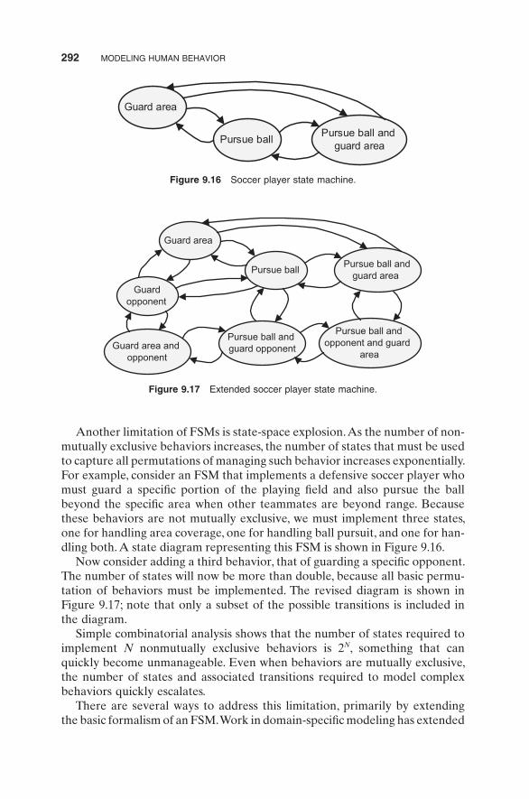
Another limitation of FSMs is state - space explosion. As the number of non-mutually exclusive behaviors increases, the number of states that must be used to capture all permutations of managing such behavior increases exponentially. For example, consider an FSM that implements a defensive soccer player who must guard a specifi c portion of the playing fi eld and also pursue the ball beyond the specifi c area when other teammates are beyond range. Because these behaviors are not mutually exclusive, we must implement three states, one for handling area coverage, one for handling ball pursuit, and one for han-dling both. A state diagram representing this FSM is shown in Figure 9.16 .
Now consider adding a third behavior, that of guarding a specifi c opponent. The number of states will now be more than double, because all basic permu-tation of behaviors must be implemented. The revised diagram is shown in Figure 9.17 ; note that only a subset of the possible transitions is included in the diagram.
Simple combinatorial analysis shows that the number of states required to implement N nonmutually exclusive behaviors is 2 N , something that can quickly become unmanageable. Even when behaviors are mutually exclusive, the number of states and associated transitions required to model complex behaviors quickly escalates.
There are several ways to address this limitation, primarily by extending the basic formalism of an FSM. Work in domain - specifi c modeling has extended
Guard area
Pursue ballPursue ball and
guard area
Figure 9.16 Soccer player state machine.
Pursue ball and opponent and guard
area Guard area and
opponent
Pursue ball and guard opponent
Guard opponent
Guard area
Pursue ballPursue ball and
guard area
Figure 9.17 Extended soccer player state machine.

TECHNIQUES FOR HUMAN BEHAVIOR MODELING 293
basic state machines to include hierarchy and concurrency as well as domain - specifi c extension for enhancing the ability of controlling behavior [23] . Hierarchical state machines include the notion of state containment , whereas one or more states are nested inside a superstate. The ability to provide hier-archical specifi cations signifi cantly reduces the number of states and decom-poses the problem in manageable pieces. Concurrency is another useful extension that allows more than one states to be active at the same time. The code associated with each active state executes during each time step. This allows isolated implementation of individual behaviors since they can all be active at the same time. The only added complexity of this approach is that when it comes to the control of the associated agent, it is possible to have contradictory commands. Looking back in the soccer player example, an implementation that utilizes concurrent states would contain only three states as shown in Figure 9.18 . Because the states are now concurrent, there is no need to code transitions; the associated code executes at each time step. However, there can only be a single point of control for the physical layer, and thus a layer is inserted between the output of concurrent state machines and the fi nal physical layer; the task of this layer is to fuse the multiple control inputs into a single and operationally logical control outcome.
As shown in Cremer et al., it is possible to implement the fusion logic by using a conservative approach that simply selects the least aggressive control input [23] . That, however, necessitates that control inputs are subject to an ordering relationship, something that is not always possible. Specifi cally, in the soccer example shown in Figure 9.18 , if the pursue ball behavior requests that the player seeks to point A but the guard area behavior requests that the player runs to point B, there is no automatic way to compare aggressiveness. In such cases, domain - specifi c handling must be implemented, something that tends to create ad hoc and nongeneralizable solutions.
An alternative to concurrent states is the use of context - based reasoning as described in Gonzalez et al. [24,25] . Contexts are “ heavyweight ” states that
Guard opponent
Guard area Pursue ball
Control fusion
Final control outcome
Figure 9.18 Fusing concurrent state control.

294 MODELING HUMAN BEHAVIOR
are effectively prioritized through a series of sentinel functions that determine if a particular context should be engaged. A sentinel function associated with each context is sequentially engaged in context priority order. The sentinel function assesses the situation and if it determines that its context can handle it, it engages the context; otherwise, the next sentinel function is called. Once engaged, a context gives up control voluntarily when it considers its task com-pleted, or it can be preempted by a higher priority context, since the sentinel functions are consulted on a continuous basis. A possible implementation of the soccer behavior using context - based reasoning is depicted in Figure 9.19 . Note that a default behavior is always present and will engage if none of the other contexts engage in order to provide some reasonable, although purpose-less, behavior. An example of combining the formalism of hierarchical state machines and context - based reasoning for guiding an autonomous vehicle in an urban environment is described in Patz et al. [26] .
Finally, a formalism that incorporates hierarchy, concurrency, communica-tion, and a fl exible visual specifi cation language is statecharts [27,28] . As ini-tially presented, statecharts target discrete - event systems but can easily be extended to support behavior modeling in discrete time simulations. Because they support concurrent execution, referred to as AND states in statechart nomenclature, they address state - space explosion; in addition, statecharts support hierarchy, where states can belong to other states and are only active when the parent state is active. Statecharts also formalize the notion of activity functions associated with each state and the general form of transitions as Boolean functions that are driven by either external events or internal logic. Statecharts also introduce communication in the form of broadcast events, which are events that are received by more than one concurrent state machine
Guard opponent
Guard area
Pursue ball
Applicable?
Applicable?
Applicable?
Y
N
N
Y
Y
Default
N
Figure 9.19 Context - based reasoning implementation of a soccer player.
TECHNIQUES FOR HUMAN BEHAVIOR MODELING 295
and result in transitions of the same name in all superstates. Statecharts were initially developed to support practical specifi cation of real - time systems, but are used extensively for numerous applications including human behavior modeling.
RBS s
The RBSs paradigm is an alternative approach to developing human behavior models. At its core, an RBS is rather simple, consisting of a set of rules, working memory, and an inference engine. The rules are pairs of if - then state-ments that each encodes a distinct condition and rational action both of whose domain is application specifi c. All associated data reside on the working memory, which initially presents the input of the external world, effectively a snapshot of the situation that an agent must handle. A rule fi res when the if portion is true. When a rule fi res, the action portion of the rule can have an arbitrary effect on the working memory. The inference engine engages when multiple rules are eligible to fi re and implements a confl ict resolution scheme to select the one rule that fi res. This process continues until a terminal rule fi res or until no rule is eligible to fi re. At that point, it is typical that the con-tents of the working memory represent the best information available about the system. An alternative interpretation of the function of the RBS for behav-ior modeling is the association with actions with each rule, allowing the infer-ence engine to act as a means by which to select appropriate actions based on current conditions.
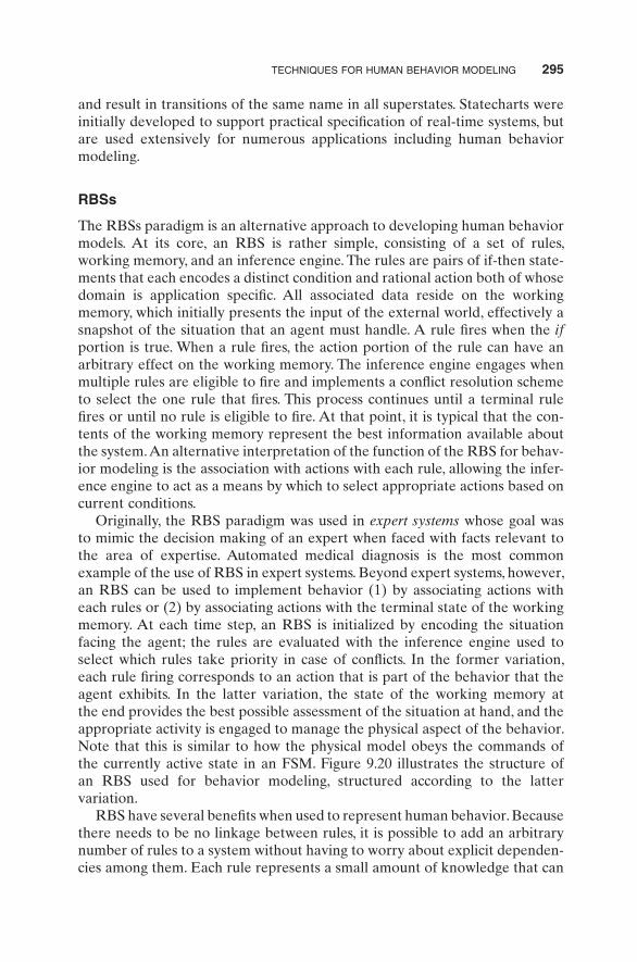
Originally, the RBS paradigm was used in expert systems whose goal was to mimic the decision making of an expert when faced with facts relevant to the area of expertise. Automated medical diagnosis is the most common example of the use of RBS in expert systems. Beyond expert systems, however, an RBS can be used to implement behavior (1) by associating actions with each rules or (2) by associating actions with the terminal state of the working memory. At each time step, an RBS is initialized by encoding the situation facing the agent; the rules are evaluated with the inference engine used to select which rules take priority in case of confl icts. In the former variation, each rule fi ring corresponds to an action that is part of the behavior that the agent exhibits. In the latter variation, the state of the working memory at the end provides the best possible assessment of the situation at hand, and the appropriate activity is engaged to manage the physical aspect of the behavior. Note that this is similar to how the physical model obeys the commands of the currently active state in an FSM. Figure 9.20 illustrates the structure of an RBS used for behavior modeling, structured according to the latter variation.
RBS have several benefi ts when used to represent human behavior. Because there needs to be no linkage between rules, it is possible to add an arbitrary number of rules to a system without having to worry about explicit dependen-cies among them. Each rule represents a small amount of knowledge that can

296 MODELING HUMAN BEHAVIOR
be used to improve the understanding of the situation, and any number of such rules can be added during development. This scalability is a signifi cant advantage for behaviors that must handle a wide range of situations and for behaviors whose defi nition is evolving during development. Another advan-tage of RBS for representing behavior is the fact that behavior need not always be deterministic. In fact, the basic paradigm does not specify specifi c constraints for the order in which rules are evaluated or the order that they execute. Modifi cations of the inference engine can be used to create variations, either stochastic or situation - based that lead to an agent taking a slightly dif-ferent course of action when presented with what seems to be identical situ-ations. Both of these reasons have made RBS a popular architecture for building the logic used for nonplayer characters in games.
By far the most comprehensive implementation of RBSs is Soar , a cognitive architecture for developing intelligent behaviors that is based on RBS [29] . Some notable extensions to the basic RBS paradigm include the use of mul-tiple level memory and explicit treatment of perception, cognition, and motor skills as part of the overall architecture. In effect, the Soar architecture not only supports the physical, tactical, and strategic behavior levels, but also includes the input portion of an agent ’ s behavior, which controls the fl ow of information from the environment to the cognitive engine. Finally, Soar includes a limited learning mechanism that can increase the available rules dynamically, thus simulating learning and adaptation. The Soar architecture implementation is in the public domain, and extensive user communities provide materials supporting its use [30,31] . Soar has been used extensively in constructing behaviors for military simulations and computer - generated forces and games [32] .
Pattern Recognition
We will now discuss pattern recognition as it applies to simulation of human behavior. Broadly speaking, pattern recognition is defi ned as the conversion
Rule-based system
Workingmemory
Behavior
Inferenceengine
Ruleaction
Terminal rule ?
Behavior implementation
Sensing and perception
Eligiblerules
Selectedrule
Y
N
Modifications
Figure 9.20 Structure of an RBS used for behavior modeling.

TECHNIQUES FOR HUMAN BEHAVIOR MODELING 297
of raw data into meaningful and contextualized data structures that can be used for further processing. Pattern recognition relates to human behavior modeling in two ways: fi rst as a means to simulate or replace sensory inputs and second as a means of actual decision making.
The former relation is focused on understanding the world through sensing stimuli, using pattern matching algorithms that focus on visual imagery, sounds, and so on. Despite popularized visions of humanoid robots that can “ see ” and “ hear, ” the ability to recognize speech or reliably react to visual stimuli is not as related to human behavior modeling as may initially appear. For example, data fed into a decision - making algorithm used in a game or military simulation does not need to be generated by a visual recognition task; similarly, recognizing speech may be convenient for a human operator but does not signifi cantly affect the process of developing human behavior models that depend on audio stimuli. In effect, behavior modeling focuses on the decision - making and cognitive issues, whereas this class of pattern recognition technologies imitates human sensory inputs.
The latter relationship, which is focused on recognizing emerging patterns as a means to decide on the course of action, is more interesting as it relates to human behavior modeling. As mentioned earlier, it has been shown that a signifi cant portion of human behavior is rooted in consciously or uncon-sciously recognizing patterns and tapping in stored memories of prior actions when faced with such patterns as a means for deciding the beset course of action. It thus makes sense to pursue human behavior modeling approaches that utilize pattern recognition as the primary driver for decision making. In this context, pattern recognition is a much higher - level process than sensory - type pattern matching, and it is better equated with situational awareness and intuition.
As a way to demonstrate the differences between sensory pattern recogni-tion and higher - level situational awareness recognition, consider modeling the behavior of a member of a sports soccer team. The low - level pattern recogni-tion tasks would be engaged in identifying the position and future trajectory of the ball and remaining players. The higher - level pattern recognition task, on the other hand, would try to identify possible opponent offensive maneu-vers or weakness in the current formation of the opponent as a means to decide on appropriate future actions. In effect, the player continuously assesses the situation by trying to identify known patterns formed by assessing the current situation. Any action taken in response to the current situation yields an outcome, which in turn affects the situation, thus closing the loop. A simpli-fi ed depiction of this process is shown in Figure 9.21 . Note that this process resembles the architecture of RBSs, with one rule stored per pattern and the associated action tied to recognition of the particular pattern.
In addition to supporting a meaningful approach to modeling human behavior, pattern matching also provides the opportunity of encoding knowl-edge. The information used to represent known patterns, typically referred to as exemplars or templates, can be augmented with new patterns and

298 MODELING HUMAN BEHAVIOR
associated rules. Depending on the techniques used for pattern recognition, it is also possible to reiterate or reject templates based on the success of the recognition tasks, in effect simulating learning by experience, or by example. In addition to mimicking how human beings learn, pattern recognition has several advantages over other techniques used for behavior modeling. Because learning occurs by example, it is not necessary to develop explicit rules that describe the patterns. In fact, it is not even necessary to be explicitly aware of the specifi c features that comprise a situation, it is only enough to have enough examples to train the algorithm to recognize the pattern.
Let us now summarize two related but distinct techniques used for pattern recognition. The fi rst is artifi cial neural networks (ANNs) and the second is HMMs. They both share traits that support learning and ruleless specifi cation of patterns, but take a different mathematical approach.
ANN s ANNs are an information processing paradigm inspired by human brain physiology [33,34] . ANNs consist of a large number of interconnected elements, referred to as neurons, a term borrowed from biology and refers to a single cell that can process and transmit information using electrical signals. In living organisms, neurons work together to perform recognitions tasks. Input stimuli is provided as input to neurons which in turn produce output signals that are routed to other neurons, eventually reaching a terminal output that controls higher cognitive functions. Neurons are interconnected through synapses; these connections govern the eventual output, given a specifi c set of inputs. In a similar manner, ANNs are constructs that mimic the interconnec-tion and operation of neurons. The ability of ANNs to recognize patterns is stored in the structure and strength of the interconnections among the indi-vidual neurons.
A key aspect of neural networks is that the connections and connection strengths can evolve based on received signals; in biologic neurons, electro-chemical processes create new connections and adjust the strength of such connections, and in ANNs, a variety of algorithms are used to adjust the
Pattern recognition
Situation
Action Outcome
Pattern memory
Figure 9.21 Simplifi ed model of pattern - recognition - driven actions.

TECHNIQUES FOR HUMAN BEHAVIOR MODELING 299
weights and connections. The important point is that in both biologic and artifi cial neural networks, this process of adjusting connections and weights represents learning. Depending on the type of learning, the network either automatically reconfi gures itself to identify patterns that appear frequently or can be trained to identify specifi c patterns of interest. The former is referred to as supervised learning, while the latter is referred to as unsupervised learn-ing. The ability to train by example combined with the ability of adaptive learning makes ANNs an attractive technique for model human behavior.
Figure 9.22 depicts the structure of an artifi cial neuron, where X i refers to inputs, W i refers to weights associated with each input, and F is the summa-tion function F W Xi ii
n= =∑ 1 that generates the output. A neuron fi res when the output value exceeds a prespecifi ed threshold. ANNs consist of multiple neurons by connecting the output of each neuron to the input of one or more other neurons creating a network. There are two primary ANN architectures: the feed - forward and the feedback.
The feed - forward network supports only forward connections, whereas the feedback network allows the creation of loops within the network. Feed - forward networks are often organized in one or more layers as shown in Figure 9.23 . Any number of hidden layers may exist, but as long as there is no loop in the directed graph formed by the network, the network remains a feed - forward network.
W1
W2
Wn
OutputFInputs
x1
x2
xn
...
Figure 9.22 Operational illustration of an artifi cial neuron.
Hidden layers
InputsOutput
Figure 9.23 Feed - forward ANN with hidden layers.
300 MODELING HUMAN BEHAVIOR
Feed - forward networks are static, in the sense that once an input is pre-sented, they produce an output in the form of a binary signal. Feedback net-works on the other hand exhibit dynamic behavior since the looped connections create a time - evolving system that changes as the output of the network is fed back into the input.
For each problem domain, effective use of an ANN involves two key steps:
(1) Identifi cation of the mapping between problem domain and ANN input (2) Training of the ANN
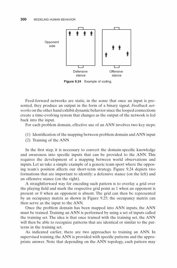
In the fi rst step, it is necessary to convert the domain - specifi c knowledge and awareness into specifi c inputs that can be provided to the ANN. This requires the development of a mapping between world observations and inputs. Let us take a simple example of a generic team sport where the oppos-ing team ’ s position affects our short - term strategy. Figure 9.24 depicts two formations that are important to identify: a defensive stance (on the left) and an offensive stance (on the right).
A straightforward way for encoding such pattern is to overlay a grid over the playing fi eld and mark the respective grid point as 1 when an opponent is present or 0 when an opponent is absent. The grid can then be represented by an occupancy matrix as shown in Figure 9.25 ; the occupancy matrix can then serve as the input to the ANN.
Once the problem domain has been mapped into ANN inputs, the ANN must be trained. Training an ANN is performed by using a set of inputs called the training set. The idea is that once trained with the training set, the ANN will then be able to recognize patterns that are identical or similar to the pat-terns in the training set.
As indicated earlier, there are two approaches to training an ANN. In supervised training, the ANN is provided with specifi c patterns and the appro-priate answer. Note that depending on the ANN topology, each pattern may
Opponent side
Defensive stance
Offensive stance
Figure 9.24 Example of coding.

TECHNIQUES FOR HUMAN BEHAVIOR MODELING 301
require its own ANN for recognition, or a composite ANN can be trained for multiple patterns. In either case, training involves adjusting the weights to ensure that the output of the network matches, as much as possible, the correct answer. A variation of this approach is reinforcement learning, in which the ANN is given guidance as to the degree of correctness of each answer it pro-duces as opposed to a strict comparison with the known correct answers. The overall approach is called supervised because it resembles a teacher supervis-ing a student during learning. In the example shown in Figures 9.24 and 9.25 , the matrices refl ecting the defensive and offensive stances would be used to train the ANN so that when either formation (or any formation that resembles them) appears, appropriate action can be taken.
Extending the example even further, another possible way to utilize an ANN is by trying to identify formations that lead to goal scoring. For example, by using games recorded a priori, the formation of the opposing team can be sampled at regular intervals along with the outcome of the formation in terms of scoring or failing to score a goal during a short period after the formation. The ANN can then be trained with a training set that consists of observed formations with the correct answer being the goal scoring outcome. Once the ANN has been trained, its output can be used to identify formations that lead to the opposite team scoring a goal, which in turn can be used to initiate spe-cifi c defensive maneuvers or other action whose aim is to counteract the opposing team.
In unsupervised learning, the ANN is provided with streams of inputs, and the weights are adjusted so that similar patterns yield similar answers. Unlike supervised learning, unsupervised learning does not require a correct answer to be associated with each input pattern in the training set. Instead, the ANN is sequentially exposed to all inputs in the training set and the weights are adjusted in an iterative manner so that the output will be correlated highly with similar patterns in the training set. Unsupervised learning is useful because it inherently explores similarities in the structure of the input data and through the association of similar output scores clusters inputs into similar groups, in effect organizing the inputs into categories. Unsupervised learning
1 1 1 1
0 0 0 0
0 0 0 0
0 0 0 0
0 0 0 0
⎡ ⎤⎢ ⎥⎢ ⎥⎢ ⎥⎢ ⎥⎢ ⎥⎢ ⎥⎣ ⎦
0 0 0 0
0 0 0 0
0 1 1 0
1 0 0 1
0 0 0 0
⎡ ⎤⎢ ⎥⎢ ⎥⎢ ⎥⎢ ⎥⎢ ⎥⎢ ⎥⎣ ⎦
Figure 9.25 Illustration of mapping environment into ANN input.

302 MODELING HUMAN BEHAVIOR
is often used in data mining applications, whose goal is to make sense of large sequences of data for which no known or obvious pattern exists. Unsupervised learning provides less utility for pragmatic human behavior modeling because it is diffi cult to associate actions without a priori knowledge of possible out-comes. An alternative to pure unsupervised learning is to utilize a hybrid approach, where the initial training is done in a supervised manner, but unsu-pervised learning is used to refi ne the ANN. The advantage of this approach is that the supervised portion provides the necessary associations between recognized patterns and actions, while the unsupervised learning acts as a self - calibrating mechanism that adapts to slight variations to known patterns that occur after the initial training has taken place.
There are several approaches used for implementing ANN training. The most straightforward approach is to use an error - correcting rule that utilizes the error signal, that is, the difference between the correct answer and the actual output of the ANN, as a means for changing the weights. Possibly the oldest approach for training ANNs was published in Hebb, and it is referred to as the Bebbian rule [35] . It uses fi rings of neurons (caused by the training set) to perform local changes to the ANN weights. Other approaches include Boltzmann learning, which is derived from thermodynamic principles [36] A summary of various training approaches in tutorial form, along with further examples of ANN usage, is given in Hertz et al. and Haykin [33,34] .
HMM s An alternative paradigm for pattern recognition as it relates to human behavior modeling is the HMM. Similar to an ANN, an HMM can be used to recognize patterns following a period of successful training from a training set. What is attractive about the HMM, however, is that the model itself often has a structural resemblance to the system being modeled. Also, the HMM can be used as a generator of behavior, not just a recognizer of patterns, and as such is worth some independent coverage.
The formal defi nition of an HMM involves several constructs. First, an HMM consists of a set S of N states, much like a state machine. The system changes states based on probabilities that dictate the chance of the system transitioning from one state to another. These probabilities are specifi ed in the state transition probability matrix A , which is an N × N matrix whose element ( i , j ) contains the probability that the state will transition from state i to state j . Unlike state machines though, the actual states and transitions of an HMM cannot be directly observed. Instead, we can only observe symbols emitted by the system while at a given state. For a given HMM, there is a set V containing M observable symbols; typically, this set of symbols is referred to as the model alphabet. The symbols emitted by each state is governed by the observation symbol probability distribution function, defi ned as a set B containing the probability that a given symbol will be emitted by the system while on a given state. The specifi cation of an HMM becomes complete after providing the initial state of an HMM, symbolized by π . In summary, an HMM is specifi ed by the following elements:

TECHNIQUES FOR HUMAN BEHAVIOR MODELING 303
S S S S
V v v v
A a a P q S q S
N
M
ij ij t j t i
= { }= { }= { } = = =[ ]+
1 2
1 2
1
, , , ;
, , , ;
, ;
……
BB b k b k P v t q S
P q Sj j k t j
i i i
= ( ){ } ( ) = =[ ]= { } = =[ ]
, @ ;
, .π π π 1
In the above, q t represents the state of the system at time t . Given an HMM, we observe a series of symbols emitted by the system being modeled; this sequence is represented by the set O: O = { O 1 , O 2 , … , O T }, where T is the number of observations. This notation is established in Rabiner, which also provides an excellent tutorial on HMMs along with the core algorithms associ-ated with their use [37] .
It is interesting to note the resemblance of an HMM to a human performing a specifi c mechanical task. We know that a person ’ s actions are driven by what is in his or her mind loosely operating according to a sequence that can be encoded in a state machine. At the same time, we cannot directly observe the person ’ s mind; this is refl ected by the hidden portion of the model. Instead, we can only observe the person ’ s actions, a fact which is refl ected in the model by the emitted symbols. Finally, the probabilistic nature of the state transitions and emitted symbols refl ects the inherent variation of human task perfor-mance and provides a natural mechanism for specifying varying levels of accuracy while driven by a single motivation.
HMMs have been used for a wide range of applications that benefi t from their similarity to human actions. In speech recognition, HMMs are used to detect individual words by detecting sequences of phonemes that together form words; by training the model, it is possible to obtain recognition that is independent of accents or other phonetic variations [38] . Similar approaches are used in various other pattern recognition fi elds, such as character recogni-tion and gesture recognition [39,40] . When it comes to human behavior model-ing, HMMs are a useful tool for recognizing high - level patterns, much like ANNs, but also for generating realistic behavior. Before explaining the spe-cifi c approach, let us summarize the basic issues associated with an HMM formulation. As described in Rabiner, there are three basic procedures that need to be addressed while working with HMMs [37] . The fi rst is evaluating or recognizing a sequence. The second procedure involves training the HMM so it recognizes a given class of observation sequences. Finally, the last pro-cedure involves producing a sequence of observations that is the best match for the model. The mathematical treatment of each of these procedures is explained in Rabiner and will not be repeated here [37] . However, we will discuss how each of them relates to human behavior modeling.
The evaluation or recognition procedure assumes that a model is given and seeks to compute the probability that the observed sequence was generated by the model. The forward – backward procedure can be used to effi ciently compute this probability, providing a recognizer with the same utility as an
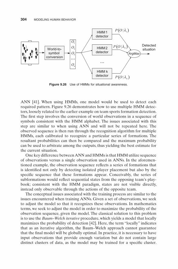
304 MODELING HUMAN BEHAVIOR
ANN [41] . When using HMMs, one model would be used to detect each required pattern. Figure 9.26 demonstrates how to use multiple HMM detec-tors, loosely related to the earlier example on team sports formation detection. The fi rst step involves the conversion of world observations in a sequence of symbols consistent with the HMM alphabet. The issues associated with this step are similar to when using ANN and will not be repeated here. The observed sequence is then run through the recognition algorithm for multiple HMMs, each calibrated to recognize a particular series of formations. The resultant probabilities can then be compared and the maximum probability can be used to arbitrate among the outputs, thus yielding the best estimate for the current situation.
One key difference between ANN and HMMs is that HMM utilize sequence of observations versus a single observation used in ANNs. In the aforemen-tioned example, the observation sequence refl ects a series of formations that is identifi ed not only by detecting isolated player placement but also by the specifi c sequence that these formations appear. Conceivably, the series of subformations would refl ect sequential states from the opposing team ’ s play-book; consistent with the HMM paradigm, states are not visible directly, instead only observable through the actions of the opposite team.
The conceptual issues associated with the training process are similar to the issues encountered when training ANNs. Given a set of observations, we seek to adjust the model so that it recognizes these observations. In mathematics terms, we seek to adjust the model in order to maximize the probability of the observation sequence, given the model. The classical solution to this problem is to use the Baum – Welch iterative procedure, which yields a model that locally maximizes the probability of detection [42] . Here, the term “ locally ” indicates that as an iterative algorithm, the Baum – Welch approach cannot guarantee that the fi nal model will be globally optimal. In practice, it is necessary to have input observations that provide enough variation but do not contain large distinct clusters of data, as the model may be trained for a specifi c cluster.
HMM 1detector
HMM 2detector
HMM kdetector
......
ArgMax
DetectedsituationWorld-to-
symbol conversion
1
2
3
n
O
O
O
O
( )1|P O l
( )2|P O l
( )| nP O l
Figure 9.26 Use of HMMs for situational awareness.

HUMAN FACTORS 305
Unlike ANN, when training an HMM we can only provide observation sequences that we wish to recognized; there is no equivalent concept of super-vised or unsupervised learning. Once trained, the resultant HMM can be used for recognition as indicated in Figure 9.26 .
The last procedure associated with HMMs is the generation of a state sequence based on observations. As in the other problems, straightforward application of the mathematics is computationally expensive, and alternative algorithms have been developed to produce equivalent results. In this case, the Viterbi algorithm is used to generate a sequence of state transitions that best match an observation [43,44] . Stated simply, this procedure seeks to unhide the model operation based on an observation. Assuming the structure of the model is known, and given an observation, this procedure will provide a series of state transitions that maximize the probability of generating the same observation sequence as the one observed. Possible applications of this technique include the reverse engineering of observed behavior into a proba-bilistic sequential model.
The ability of HMMs to adjust based on observations can be used in ways beyond straightforward recognition of patterns. In fact, the trainability of HMMs can be leveraged for purposes of encoding knowledge and creating behavioral models that have an inherent ability of learning from experience. For example, the work described in Shatkay and Kaelbling extends the basic HMM model with odometry information as a means to facilitate an autono-mous robot learn about its environment [45] . In this case, each state loosely represents the state of the robot near a position in the map, and transitions represent traveling between these confi gurations. The HMM model is aug-mented by an odometric relation matrix that represents the spatial relation-ship between such states. In this context, observations refl ect the movement of a robot; the probabilistic nature of observations compensates for the noisy measurements provided by sensors. By extending the HMM model with domain - specifi c information, this example demonstrates how the ability of an HMM to learn based on observations in this case can be leveraged for envi-ronment discovery and mapping.
HUMAN FACTORS
In recent years, researchers have begun to use several computational modeling techniques to describe, explain, predict, and demonstrate human behavior and performance, particularly in environments embodying time pressure, stress and close coupling between humans and machines. Such attempts can be clas-sifi ed loosely into the fi eld of human factors . Modeling efforts in this fi eld are usually based on data collected in traditional human factors behavioral experi-ments in laboratory - based simulators and in the actual task environments. These models aim to extend the value of empirical results by making engineer-ing predictions and attempting to explain phenomena related to basic human

306 MODELING HUMAN BEHAVIOR
performance variables in contexts ranging from human – computer interaction (HCI), workplace design, driving, health care, military and defense, and avia-tion. One example of such modeling techniques are discrete - event simulation packages such as Arena, ProModel, and Microsaint that are used to generate stochastic predictions of human performance unfolding in real time. The ulti-mate goal is the integration of cognitive modeling techniques with physical and mathematical modeling techniques and task analysis to generate compre-hensive models of human performance in the real world.
Research in the newly emerged fi eld of augmented cognition (AugCog) has demonstrated great potential to develop more intelligent computational systems capable of monitoring and adapting the systems to the changing cogni-tive state of human operators in order to minimize cognitive bottlenecks and improve task performance. Limitations in human cognition are due to intrinsic restrictions in the number of mental tasks that a person can execute at one time, and this capacity itself may fl uctuate from moment to moment depend-ing on a host of factors including mental fatigue, novelty, boredom, and stress. As computational interfaces have become more prevalent in society and increasingly complex with regard to the volume and type of information pre-sented, it is important to investigate novel ways to detect these bottlenecks and devise strategies to understand and improve human performance by effec-tively accommodating capabilities and limitations in human information pro-cessing and decision making.
The primary goal of incorporating modeling and simulation techniques in studying human behavior, therefore, is to research and develop technologies capable of extending, by an order of magnitude or more, the information management capacity of individuals working with modern day computing technologies. This includes the study of methods for addressing cognitive bottlenecks (e.g., limitations in attention, memory, learning, comprehension, visualization abilities, and decision making) via technologies that assess the user ’ s cognitive status in real time. A computational interaction employing such novel system concepts monitors the state of the user, through behavioral, psychophysiological, and/or neurophysiological data acquired from the user in real time, and then adapts or augments the computational interface to sig-nifi cantly improve its performance on the task at hand based on a series of complex computations.
At the most general level, human behavior modeling has the explicit goal of utilizing methods and designs that harness computation and explicit knowl-edge about human limitations to open bottlenecks and address the biases and defi cits in human cognition. This can be done through continual background sensing, learning, and inferences to understand trends, patterns, and situations relevant to a user ’ s context and goals. At its most basic level, at least four variables are critical — a method to determine and quantify current user state, a technique to evaluate change of state in cognitive terms, a mechanism to translate the change in cognition into computational terms, and an underlying computational architecture to integrate these components. In order to under-

HUMAN FACTORS 307
stand better the cognitive variables that drive the modeling process, it is fi rst important to begin with a clear understanding of the basic process of human information processing.
Model of Human Information Processing
Human information processing theory addresses how people receive, store, integrate, retrieve, and use information. There are a few basic principles of information processing that most cognitive psychologists agree with:
(1) The mental system has limited capacities; that is, bottlenecks in the fl ow and processing of information occur at very specifi c points.
(2) A control mechanism is required to oversee the encoding, transforma-tion, processing, storage, retrieval, and utilization of information. This control mechanism requires processing power and varies as a function of the diffi culty of the task.
(3) Sensory input is combined with information stored in memory in order to construct meaning. Stimuli that have been associated with some meaning lead to more detailed processing eventually leading to action execution.
(4) Information fl ow is typically two way — environmental stimuli infl uence information processing; processed information in turn leads to action execution, which alters environmental stimuli.
A comprehensive model of human information processing recently pro-posed provides a useful framework for analyzing the different psychological processes used in interacting with systems as described below [46] .
Stage 1: Sensory Processing . At this stage, environmental events gain initial access to the brain. Any incoming information is temporarily prolonged and stored in the short - term sensory store (STSS). The STSS typically prolongs the experience of a stimulus for durations as short as 0.5 s (visual stimuli) to as long as 2 – 4 s (auditory stimuli). If the human is distracted during this brief period, the information is permanently lost from the system.
Stage 2: Perception . Raw sensory relayed from the STSS must next be inter-preted, or given meaning, through the stage of perception. At this stage, infor-mation processing proceeds automatically and rapidly, and requires minimal attention. Also, perception is driven both by raw sensory input (called “ bot-tom - up ” processing) as well as inputs and expectations derived from long - term memory (called “ top - down ” processing). The speed and relative automaticity of perception is what distinguishes it from the next stage of “ cognition, ” which is discussed below.
Stage 3: Cognition and Memory . Cognitive operations generally require more time, mental effort, and attention. This is because cognition comprises reasoning, thinking, rehearsal, and several mental transformations, all of

308 MODELING HUMAN BEHAVIOR
which are carried out in a temporary memory store known as working memory. Processes in working memory are highly vulnerable to disruption when atten-tion is diverted to other activities. If information is processed uninterrupted at this stage, it is permanently stored in long - term memory and drives response selection and action execution.
Stage 4: Response Selection and Execution . The understanding of the situa-tion, achieved through perception and augmented by cognitive transforma-tions, often triggers an action transformation — the selection of a response. It is important to note that the mere selection of a response depicts the stage of decision making. Actual execution of the response requires coordination of muscles for controlled movement to assure that the goal is correctly obtained.
Across all stages of perception to cognition to response selection and execu-tion, the presence of continuous feedback and attention is an important deter-minant of accuracy of information processing. In the section below, we will now discuss how these human information processing variable can be trans-lated into improvements in human interaction with technology.
HUMAN – COMPUTER INTERACTION
An increasing portion of computer use is dedicated to supporting intellectual and creative enterprise. The media is so fi lled with stories about computers that raising public consciousness of these tools seems unnecessary. However, humans in large part are still uncomfortable interacting with computers. In addition to perceived system complexities, humans are subject to the underly-ing fear of making mistakes, or might even feel threatened by a computer that is “ smarter than ” the user. These negative perceptions are generated, in part, by poor designs, hostile and vague error messages, unfamiliar sequences of actions, or deceptive anthropomorphic style [47] .
Human – computer interaction (HCI) is the detailed study of the interaction between people (users) and computers [48,49] . It is often regarded as the intersection of computer science, behavioral sciences, design, and several other fi elds of study such a communication, business, and language. Interaction between users and computers occurs at the user interface, which includes both software and hardware. Because HCI studies a human and a machine in con-junction, it draws from supporting knowledge on both the machine and the human side. On the machine side, techniques in computer graphics, operating systems, programming languages, and development environments are relevant. On the human side, communication theory, graphic and industrial design dis-ciplines, linguistics, cognitive psychology, and human factors are relevant.
HCI differs from human factors, a closely related fi eld, in that in the former there is more of a focus on users working with computers rather than other kinds of machines or designed artifacts, and an additional focus on how to implement the (software and hardware) mechanisms behind computers to
HUMAN–COMPUTER INTERACTION 309
support HCI. HCI also differs with ergonomics in that in HCI there is less of a focus on repetitive work - oriented tasks and procedures, and much less emphasis on physical stress and the physical form or industrial design of physi-cal aspects of the user interface, such as the physical form of keyboards and mice.
The ultimate goal of HCI is to improve the interaction between users and computers by making computers more usable and receptive to the user ’ s needs. Specifi cally, HCI is concerned with:
(1) Methodologies and processes for designing interfaces (i.e., given a task and a class of users, design the best possible interface within given constraints [47] , optimizing for a desired property such as learning ability or effi ciency of use)
(2) Methods for implementing interfaces (e.g., software toolkits, effi cient algorithms)
(3) Techniques for evaluating and comparing interfaces (4) Developing new interfaces and interaction techniques (5) Developing descriptive and predictive models and theories of
interaction
Two areas of study, however, have substantial overlap with HCI even as the focus of inquiry shifts [47] . In computer - supported cooperative work (CSCW), emphasis is placed on the use of computing systems in support of the collaborative work of a group of people. In the study of personal informa-tion management (PIM), human interactions with the computer are placed in a larger informational context. People may work with many forms of informa-tion, some computer - based, others not (e.g., whiteboards, notebooks, sticky notes, refrigerator magnets) in order to understand and effect desired changes in their world. In the next section, we examine different methods for demys-tifying HCI and the reasons for its inception.
User Interface
In the 1950s, the approach to system design was primarily one of comparing human and machine attributes. Function allocation was accorded based on the strengths of each [50] . For example, humans are better at complex decision - making tasks that involve using information from past experience; on the other hand, machines are better at performing large tasks of a monotonous nature such as multiplying six - digit numbers! This allocation of function that attempts to capitalize on the strengths of each entity is known as “ compensa-tory ” principle. Fitts ’ list that delineated strengths of each (humans vs. machines) was initially known as men are best at - machines are best at (MABA - MABA). In the modern day, this has been changed to the more politically correct humans are best at - machines are best at (HABA - MABA) [51] .

310 MODELING HUMAN BEHAVIOR
Human Strengths Based on the HABA - MABA model, human strengths have been identifi ed as:
(1) Speed — Humans can work fast for short bursts when feeling energetic. However, human reaction times are typically much slower than machines.
(2) Accuracy — Humans are capable of accurate performance when atten-tion to detail is a requirement. However, it is diffi cult to sustain high levels of accuracy for long periods of time.
(3) Repetitive actions — Humans are better than machines at applying past experience and learning when a task is to be performed repeatedly; however, humans are easily prone to boredom and fatigue.
(4) Perceptual skills — Humans possess excellent perceptual skills, especially applicable to tasks that require pattern detection and interpretation.
(5) Memory — Human memory is very situation dependent. Information that is meaningful to the individual is remembered and recalled with alarming clarity; however, human memory is often selective and not always reliable.
(6) Decision making — Humans are particularly good at using rules of thumb or “ heuristics ” under time pressure and resource deprivation; addition-ally, humans are very good at extrapolating from past experience.
(7) Intelligence — It is no secret that human intelligence has been identifi ed as superior to any other species.
Computer Strengths Based on the HABA - MABA model, machine strengths have been identifi ed as:
(1) Speed — Machines can work fast for long periods of time. Machine reac-tion times are typically much faster than humans.
(2) Accuracy — Machines are capable of maintaining high standards of accuracy when programmed accurately. However, they are prone to catastrophic breakdowns in accuracy when faced with new situations or design glitches.
(3) Repetitive actions — Machines are excellent at repeating actions in a consistent manner.
(4) Memory — Machine memory is very reliable in that all items stored in memory can be accessed quickly; machine memory is limited but typi-cally has large capacity.
(5) Decision making — Machines typically function on a rule - based approach; they are good at deductive reasoning, but perform poorly in new situations.
(6) Intelligence — Machine intelligence is limited to what it is hardwired to do by the designer.

HUMAN–COMPUTER INTERACTION 311
Desired Interaction between Humans and Computers Although the above list provides very clear distinctions between humans and computers, the distinctions are oversimplifi ed and somewhat sterile. Generally, machines evolve much faster than suggested by the list above; at the same time, human performance can be progressively improved to overcome the aforementioned shortcomings via training and experience. Furthermore, the list above is an oversimplifi cation in that although some tasks are more effi ciently performed by a human, there are often compelling reasons for using a machine to perform them (e.g., moving hazardous material). On the other hand, humans are unique in that they have an affective (emotional, motivational) component in most of their activities, which may well provide an additional reason for allo-cating work to humans versus machine. In summary, allocation of functions based purely on the strengths and weaknesses of humans and machines is a very limited approach, which rarely works on its own [52] . It is more important to create a degree of synergistic activity or collaboration between systems and humans such that the two can work as “ teammates. ”
“ Computer consciousness ” in the general public is a possible solution to creating the abovementioned synergy between humans and computers. Exploratory applications of HCI where such consciousness can be created include World Wide Web browsing, search engines, and different types of scientifi c simulation [47,48] . Creative environments include writing work-benches, artist or programmer workstations, and architectural design systems. Collaborative interfaces enable two or more people to work together, even if the users are separated by time and space, through the use of electronic text, voice, and video mail; through electronic meeting systems that facilitate face - to - face meetings; or through groupware that enables remote collaborators to work concurrently on a document, map, spreadsheet, or image. In these tasks, users may be knowledgeable in the work domain but novices in underlying computer concepts. One of the most effective solutions to humans ’ lack of knowledge has been the creation of “ point - and - click ” direct manipulation (DM) representations of the world of action, supplemented by keyboard shortcuts. In the next section, we discuss two popular metaphors for imple-menting effective HCI — DM and dialog boxes.
Metaphors and Designing for HCI
DM is a style of human machine interaction design, which features a natural representation of task objects and actions promoting the notion of people performing a task themselves (directly) not through an intermediary like a computer. DM is based on the principle of virtuality — a representation of reality that can be physically manipulated. A similar concept was conveyed by the principle of transparency — the user should be able to apply intellect directly to the task; that is, the user should feel involved directly with the objects to be manipulated rather than communicate with an intermediary [53] . DM essentially involves continuous representation of objects of interest, and

312 MODELING HUMAN BEHAVIOR
rapid, reversible, incremental actions and feedback. The intention is to allow a user to directly manipulate objects presented to them, using actions that correspond at least loosely to the physical world. Having real - world metaphors for objects and actions make it easier for a user to learn and use an interface (thereby making the interface more natural or intuitive). Rapid, incremental feedback allows a user to make fewer errors and complete tasks in less time, because they can see the results of an action before completing the action. An example of DM is resizing a graphic shape, such as a rectangle, by dragging its corners or edges with a mouse [48] .
DM is a topic to which computer science, psychology, linguistics, graphic design, and art all contribute substantially. The computer science foundation areas of computer architecture and operating systems provide us with an understanding of the machines upon which human – computer interface styles such as DM are implemented. This understanding allows us to determine capabilities and limitations of computer platforms, thereby providing bound-aries for realistic HCI designs. As with any computer application develop-ment, DM interface development benefi ts greatly from the computer science foundation areas of algorithms and programming languages. The specialized fi eld of computer graphics can also make a key contribution.
A DM interface possesses several key characteristics. As mentioned earlier, a visual representation of objects and actions is presented to a person in con-trast to traditional command line languages. The visual representation usually takes the form of a metaphor related to the actual task being performed. For example, computer fi les and directories are represented as documents and fi le cabinets in a desktop publishing system. The module used to permanently delete documents from a computer (the “ recycle bin ” ) physically resembles an actual trash dumpster into which “ waste ” materials can be dragged and dropped. The use of metaphors allows a person to tap their analogical reason-ing power when determining what actions to take when executing a task on the computer [54] . For example, this property is drawn upon heavily by desktop metaphors in their handling of windows like sheets of paper on a desk. This enhances the impression that the person is performing the task and is in control at all times.
Given a thoughtful design and strong implementation, an interactive system employing DM principles can realize many benefi ts. Psychology literature cites the strengths of visual representations in terms of learning speed and retention. DM harnesses these strengths resulting in systems whose operation is easy to learn and use and diffi cult to forget [55] . Because complex syntax does not have to be remembered and analogical reasoning can be used, fewer errors are made than in traditional interfaces. In situations where errors are unavoidable, they are easily corrected through reversible actions. Reversible actions also foster exploration because the fear of permanently damaging something has been diminished. This increases user confi dence and mastery and improves the overall quality of HCI.
HUMAN–COMPUTER INTERACTION 313
Dialog Box Manipulation In graphic user interfaces, a dialog box is a special window used in user interfaces to display information to the user, or to get a response if needed [56] . They are so called because they form a dialog between the computer and the user — either informing the user of something or requesting input from the user, or both. It provides controls that allow the user to specify how to carry out an action. Dialog boxes are classifi ed as modal or modeless, depending on whether they block interaction on the application that triggered the dialog or not. Different types of dialog boxes are used for different sorts of user interaction. The simplest type of dialog box is the alert that displays a message and requires only an acknowledgment (by clicking “ OK ” ) that the message has been read. Alerts are used to provide simple confi rmation of an action, or include program termination notices or inten-tional closing by the user.
When used appropriately, dialog boxes are a great way to give power and fl exibility to the program. When misused, dialog boxes are an easy way to annoy users, interrupt their fl ow, and make the program feel indirect and tedious to use. Dialog boxes typically demand attention, especially when they are modal; furthermore, since they pop out unexpectedly on some portion of the screen, there is a danger that they will obscure relevant information. Therefore, they are most effective when design characteristics match usage requirements.
A dialog box ’ s design is largely determined by its purpose (to offer options, ask questions, provide information or feedback), type (modal or modeless), and user interaction (required, optional response, or acknowledgment). Its usage is largely determined by the context (user or program initiated), prob-ability of user action, and frequency of display [57] .
Characteristics of “ Effective ” Dialog Boxes Modal dialog boxes that are typically used to signal critical system events should have the following characteristics:
(1) Displayed in a window that is separate from the user ’ s current activity.
(2) Require interaction — can break the user ’ s fl ow such that users must close the dialog box before continuing work on the primary task.
(3) Use a delayed commit model — changes are not made until explicitly committed.
(4) Have command buttons that commit to a specifi c action (e.g., shutdown program, report error).
Modeless dialog boxes that are used to signal repetitive and less critical incidents should have these characteristics:
(1) Displayed in context using a task pane or with an independent window.

314 MODELING HUMAN BEHAVIOR
(2) Do not require interaction — users can switch between the dialog box and the primary window as desired and can delay response.
(3) Can use an immediate commit model — changes are made immediately. (4) Have standard command buttons (e.g., OK, yes, close) that close the
window.
Overall, the primary criterion for dialog box design must ensure that they are distinct enough for users to distinguish them from the background. However, at the same time, they should be minimally disruptive visually. The key among these requirements is that they should be accompanied by a meaningful title, be consistent in style and layout (margins, font, white space, justifi cation), and must be controlled entirely by DM (or point - and - click mechanisms).
Documenting Interface Design Storyboards are graphic organizers such as a series of illustrations or images displayed in sequence for the purpose of previsualizing a motion picture, animation, motion graphic, or interactive media sequence, including Web site interactivity. Although traditionally used in the motion picture industry, the term storyboard has more recently come to be used in the fi elds of Web development, software development, and instructional design to present and describe user interfaces and electronic pages in written format as well as via audio and motion [58] .
Storyboards are typically created in a multiple step process. They can be created by hand drawing or digitally on the computer. If drawing by hand, the fi rst step is to create or download a storyboard template. These appear like a blank comic strip, with space for comments and dialog. Then a thumbnail storyboard is sketched. “ Thumbnails ” are rough sketches, not much bigger than a thumbnail. This is followed by the actual storyboarding process wherein more detailed and elaborate storyboard images are created.
The actual storyboard can be created by professional storyboard artists on paper or digitally by using 2D storyboarding programs. Some software appli-cations even supply a stable of storyboard - specifi c images making it possible to quickly create shots that express the designer ’ s intent for the story. These boards tend to contain more detailed information than thumbnail storyboards and convey components of mood, emotions, personality, and other psycho-logical variables [59] . If needed, 3D storyboards can be created (called “ tech-nical previsualizations ” ). The advantage of 3D storyboards is that they show exactly what the fi nal product will look like. The disadvantage of 3D is the amount of time it takes to build and construct the storyboard.
The primary advantage of using storyboards to HCI is that it allows the user to experiment with changes in the storyline to evoke stronger reaction or interest. Flashbacks, for instance, are often the result of sorting storyboards out of chronological order to help build suspense and interest. The process of visual thinking and planning allows a group of people to brainstorm together,
HUMAN–COMPUTER INTERACTION 315
placing their ideas on storyboards and then arranging the storyboards on the wall [59] . This fosters more ideas and generates consensus inside the group leading to more effective HCI.
Prototypes are common. During the process of design, there is great uncer-tainty as to whether a new design will actually do what is desired to do. A prototype is often used as part of the product design process to allow engineers and designers the ability to explore design alternatives, test theories, and confi rm performance prior to starting production of a new product. The cre-ation of prototypes is based on the counterintuitive philosophy that the easiest way to build something is to fi rst build something else! In general, an iterative series of prototypes will be designed, constructed, and tested as the fi nal design emerges and is prepared for production [60] . With rare exceptions, multiple iterations of prototypes are used to progressively refi ne the design. A common strategy is to design, test, evaluate, and then modify the design based on the analysis of the prototype.
In many products, it is common to assign the prototype iterations in Greek letters. For example, a fi rst iteration prototype may be called an “ Alpha ” prototype. Often, this iteration is not expected to perform as intended and some amount of failures or issues are anticipated. Subsequent prototyping iterations (Beta, Gamma, etc.) will be expected to resolve issues and perform closer to the fi nal production intent.
In many product development organizations, prototyping specialists are employed — individuals with specialized skills and training in general fabrica-tion techniques that can help bridge between theoretical designs and the fabrication of prototypes. There is no general agreement on what constitutes a “ good prototype, ” and the word is often used interchangeably with the word “ model, ” which can cause confusion. In general, “ prototypes ” fall into four basic categories:
(1) Proof - of - principle prototypes (also called “ breadboards ” ) are used to test some aspect of the intended design without attempting to exactly simulate the visual appearance, choice of materials, or intended manu-facturing process. Such prototypes can be used to demonstrate “ behav-ioral ” characteristics of a particular design such as range of motion, mechanics, sensors, architecture, and so on. These types of prototypes are generally used to identify which design options will not work, or where further development and testing are necessary.
(2) Form study prototypes allow designers to explore the basic size, look, and feel of a product without simulating the actual function, behavior, or exact physical appearance of the product. They can help assess ergonomic factors and provide insight into gross visual aspects of the product ’ s fi nal form. Form study prototypes are often hand - carved or machined models from easily sculpted, inexpensive materials (e.g., ure-thane foam), without representing the intended color, fi nish, or texture. Due to the materials used, these models are intended for internal

316 MODELING HUMAN BEHAVIOR
decision making and are generally not durable enough or suitable for use by representative users or consumers.
(3) Visual prototypes capture the intended design aesthetic and simulate the exact appearance, color, and surface textures of the intended product but will not actually embody the functions or “ behaviors ” of the fi nal product. These prototypes are suitable for use in market research, executive reviews and approval, packaging mock - ups, and photo shoots for sales literature.
(4) Functional prototypes (also called “ working prototypes ” ) are, to the greatest extent practical, attempt to simulate the fi nal design, aesthet-ics, materials, and functionality of the intended design all in one package. The functional prototype may be reduced in size (scaled down) in order to reduce costs. The construction of a fully working full - scale prototype is the engineer ’ s fi nal check for design fl aws and allows last minute improvements to be made before larger production runs are ordered.
Characteristics and Limitations of Prototypes Engineers and prototyp-ing specialists seek to understand the limitations of prototypes to exactly simulate the characteristics of their intended design. First, a degree of skill and experience is necessary to effectively use prototyping as a design verifi ca-tion tool [61] . Second, it is important to realize that by their very defi nition, prototypes will represent some compromise from the fi nal production design. Due to differences in materials, processes, and design fi delity, it is possible that a prototype may fail to perform acceptably, whereas the production design may have been sound. A counterintuitive idea is that prototypes may actually perform acceptably, whereas the fi nal production design may be fl awed since prototyping materials and processes may occasionally outperform their production counterparts.
Although iterative prototype testing can possibly reduce the risk that the fi nal design may not perform acceptably, prototypes generally cannot elimi-nate all risk. There are pragmatic and practical limitations to the ability of a prototype to match the intended fi nal performance of the product and some allowances and engineering judgments are often required before moving forward with a production design. Building the full design is often expensive and can be time - consuming, especially when repeated several times. As an alternative, “ rapid prototyping ” or “ rapid application development ” tech-niques are used for the initial prototypes, which implement part, but not all, of the complete design. This allows designers and manufacturers to rapidly and inexpensively test the parts of the design that are most likely to have problems, solve those problems, and then build the full design.
Unifi ed Modeling Diagrams Unifi ed Modeling Language (UML) is a stan-dardized general - purpose modeling language in the fi eld of software engineer-

HUMAN–COMPUTER INTERACTION 317
ing. UML includes a set of graphic notation techniques to create abstract models of specifi c systems. UML is an open method used to specify, visualize, construct, and document the artifacts of an object - oriented software - intensive system under development. UML offers a standard way to write a system ’ s blueprints including conceptual components such as business processes. In addition, UML can also help document concrete variables such as program-ming language statements, database schemas, and reusable software compo-nents. UML combines the best practice from data modeling concepts and component modeling. It can be used with all processes, throughout the soft-ware development cycle, and across different implementation technologies. UML is extensible and models may be automatically transformed to other representations (e.g., Java) by means of transformation languages.
Typically UML diagrams represent two different views of a system model [62] :
(1) Static (or structural) view emphasizes the static structure of the system using objects, attributes, operations, and relationships. Structure dia-grams emphasize what components must be incorporated in the system being modeled. Since structure diagrams represent the structure of a system, they are used extensively in documenting the architecture of software systems: • Class diagram describes the structure of a system by showing the
system ’ s classes, their attributes, and the relationships among the classes.
• Component diagram depicts how a software system is split into com-ponents and shows the dependencies among these components.
• Composite structure diagram describes the internal structure of a class and the collaborations that this structure makes possible.
• Deployment diagram serves to model the hardware used in system implementations and the execution environments and artifacts deployed on the hardware.
• Object diagram shows a complete or partial view of the structure of a modeled system at a specifi c time.
• Package diagram depicts how a system is split up into logical group-ings by showing the dependencies among these groupings.
(2) Dynamic (or behavioral) view emphasizes the dynamic behavior of the system by showing collaborations among objects and changes to the internal states of objects. Behavior diagrams emphasize what must happen in the system being modeled. Since behavior diagrams illustrate the behavior of system, they are used extensively to describe the func-tionality of software systems: • Activity diagram represents the business and operational step - by - step
workfl ows of components in a system. An activity diagram shows the overall fl ow of control.

318 MODELING HUMAN BEHAVIOR
• State machine diagram is a standardized notation to describe many systems, from computer programs to business processes.
• Use case diagram shows the functionality provided by a system in terms of actors, their goals represented as use cases, and any depen-dencies among those use cases.
Although UML is a widely recognized and used modeling standard, it is frequently criticized for being gratuitously large and complex. In addition, weak visualizations that employ line styles that are graphically very similar frequently disrupt learning, especially when required of engineers lacking the prerequisite skills. As with any notational system, UML is able to represent some systems more concisely or effi ciently than others. Thus, a developer gravitates toward solutions that reside at the intersection of the capabilities of UML and the implementation language. This problem is particularly pro-nounced if the implementation language does not adhere to orthodox object - oriented doctrine, as the intersection set between UML and implementation language may be that much smaller. Lastly, UML has been proven to be aes-thetically inconsistent due to the arbitrary mixing of abstract notation (2D ovals, boxes, etc.) that make UML appear jarring and visually disruptive to the user.
Web Design A Web site is a collection of information about a particular topic or subject. Designing a Web site is defi ned as the arrangement and cre-ation of Web pages, each page presenting some information of relevance to the primary theme of the Web site. There are many aspects (primarily design concerns) in the process of Web design, and due to the rapid development of the Internet new aspects constantly emerge [63] . For typical commercial Web sites, the basic aspects of design are the following:
• Content: Information on the site should be relevant to the site and should target the area of the public that the Web site is concerned with.
• Usability: The site should be user - friendly, with the interface and naviga-tion simple and reliable.
• Appearance: The graphics and text should include a single style that fl ows throughout, to show consistency. The style should be professional, appeal-ing, and relevant.
• Visibility: The site must be easy to fi nd by typing in common keywords via most major search engines and advertisement media.
Web site design crosses multiple disciplines of information systems, HCI, and communication design. Typically, the observable content (e.g., page layout, graphics, text, audio, etc.) is known as the “ front end ” of the Web site. The “ back end ” comprises the source code, invisible scripted functions, and the server - side components that process the output from the front end.

HUMAN–COMPUTER INTERACTION 319
Depending on the size of a Web development project, it may be carried out by a multiskilled individual or may represent collaborative efforts of several individuals with specialized skills. As in any collaborative design, there are confl icts between differing goals and methods of Web site designs. Some of the ongoing challenges in Web design are discussed below.
Form versus Function Frequently, Web designers may pay more attention to how a page “ looks ” while neglecting other important functions such as the readability of text, the ease of navigating the site, or ease of locating the site [64] . As a result, the user is often bombarded with decorative graphics at the expense of keyword - rich text and relevant text links. Assuming a false dichot-omy that form and function are mutually exclusive overlooks the possibility of integrating multiple disciplines for a collaborative and synergistic solution. In many cases, form follows function. Because some graphics serve commu-nication purposes in addition to aesthetics, how well a site works may depend on the graphic design ideas in addition to the professional writing consider-ations [64] .
To be optimally accessible, Web pages and sites must conform to certain accessibility principles. Some of the key accessibility principles most relevant to HCI can be grouped into the following main points:
(1) Use semantic markup that provides a meaningful structure to the document (i.e., Web page). Semantic markup also refers to semanti-cally organizing the Web page structure and publishing Web services description accordingly so that they can be recognized by other Web services on different Web pages. Standards for semantic Web are set by the Institute of Electrical and Electronics Engineers (IEEE).
(2) Provide text equivalents for any nontext components (e.g., images, multimedia).
(3) Use hyperlinks that make sense when read out of context (e.g., avoid “ Click Here ” ; instead, have the user click on a meaningful word that is relevant to the context).
(4) Author the page so that when the source code is read line - by - line by user agents (such as screen readers), it remains intelligible.
Liquid versus Fixed Layouts On the Web, the designer generally has little to no control over several factors, including the size of the browser window, the Web browser used, the input devices used (mouse, touch screen, keyboard, number pad, etc.), and the size, design, and other characteristics of the fonts users have available (installed) on their own computers [65] . Some designers choose to control the appearance of the elements on the screen by using spe-cifi c width designations. When the text, images, and layout do not vary among browsers, this is referred to as fi xed - width design. Advocates of fi xed - width design argue for the designers ’ precise control over the layout of a site and the placement of objects within pages.
320 MODELING HUMAN BEHAVIOR
Other designers choose a more liquid approach, wherein content can be arranged fl exibly on users ’ screens, responding to the size of their browsers ’ windows. Proponents of liquid design prefer greater compatibility with users ’ choice of presentation and more effi cient use of the screen space available. Liquid design can be achieved by setting the width of text blocks and page modules to a percentage of the page, or by avoiding specifying the width for these elements altogether, allowing them to expand or contract naturally in accordance with the width of the browser. It is more in keeping with the origi-nal concept of HTML, that it should specify, not the appearance of text, but its contextual function, leaving the rendition to be decided by users ’ various display devices.
Web page designers (of both types) must consider how their pages will appear on various screen resolutions [66] . Sometimes, the most pragmatic choice is to allow text width to vary between minimum and maximum values. This allows designers to avoid considering rare users ’ equipment while still taking advantage of available screen space.
Adobe Flash (formerly Macromedia Flash) is a proprietary, robust graphics animation or application development program used to create and deliver dynamic content, media (such as sound and video), and interactive applica-tions over the Web via the browser. Many graphic artists use Flash because it gives them exact control over every part of the design, and anything can be animated as required. Flash can use embedded fonts instead of the standard fonts installed on most computers.
Criticisms of Flash include the use of confusing and nonstandard user inter-faces, the inability to scale according to the size of the Web browser, and its incompatibility with common browser features (such as the back button). An additional criticism is that the vast majority of Flash Web sites are not acces-sible to users with disabilities (for vision - impaired users). A possible HCI - relevant solution is to specify alternate content to be displayed for browsers that do not support Flash. Using alternate content will help search engines to understand the page and can result in much better visibility for the page.
CONCLUSION
Based on human behavior taxonomy, several levels of human behavior were identifi ed, and a variety of tools and techniques supporting modeling of this behavior were presented in this section. These techniques include fuzzy logic, for low - level humanlike control of external processes, and state machines, RBSs, and pattern recognition methods for higher - level behaviors. It is impor-tant to note that these tools and techniques are not meant to work in isolation; in fact, comprehensive solutions for behavior modeling often utilize multiple techniques at the same time. As an extreme example that utilizes all of the aforementioned approaches, consider the simulation of an intelligent agent that involves movement within a vehicle, maybe a car or boat. Any of the state
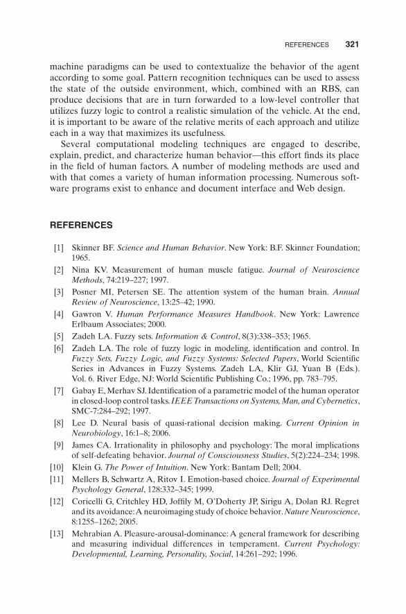
REFERENCES 321
machine paradigms can be used to contextualize the behavior of the agent according to some goal. Pattern recognition techniques can be used to assess the state of the outside environment, which, combined with an RBS, can produce decisions that are in turn forwarded to a low - level controller that utilizes fuzzy logic to control a realistic simulation of the vehicle. At the end, it is important to be aware of the relative merits of each approach and utilize each in a way that maximizes its usefulness.
Several computational modeling techniques are engaged to describe, explain, predict, and characterize human behavior — this effort fi nds its place in the fi eld of human factors. A number of modeling methods are used and with that comes a variety of human information processing. Numerous soft-ware programs exist to enhance and document interface and Web design.
REFERENCES
[1] Skinner BF . Science and Human Behavior . New York : B.F. Skinner Foundation ; 1965 .
[2] Nina KV . Measurement of human muscle fatigue . Journal of Neuroscience Methods , 74 : 219 – 227 ; 1997 .
[3] Posner MI , Petersen SE . The attention system of the human brain . Annual Review of Neuroscience , 13 : 25 – 42 ; 1990 .
[4] Gawron V . Human Performance Measures Handbook . New York : Lawrence Erlbaum Associates ; 2000 .
[5] Zadeh LA . Fuzzy sets . Information & Control , 8 ( 3 ): 338 – 353 ; 1965 . [6] Zadeh LA . The role of fuzzy logic in modeling, identifi cation and control . In
Fuzzy Sets, Fuzzy Logic, and Fuzzy Systems: Selected Papers , World Scientifi c Series in Advances in Fuzzy Systems. Zadeh LA , Klir GJ , Yuan B (Eds.). Vol. 6 . River Edge, NJ : World Scientifi c Publishing Co. ; 1996 , pp. 783 – 795 .
[7] Gabay E , Merhav SJ . Identifi cation of a parametric model of the human operator in closed - loop control tasks . IEEE Transactions on Systems, Man, and Cybernetics , SMC - 7 : 284 – 292 ; 1997 .
[8] Lee D . Neural basis of quasi - rational decision making . Current Opinion in Neurobiology , 16 : 1 – 8 ; 2006 .
[9] James CA . Irrationality in philosophy and psychology: The moral implications of self - defeating behavior . Journal of Consciousness Studies , 5 ( 2 ): 224 – 234 ; 1998 .
[10] Klein G . The Power of Intuition . New York : Bantam Dell ; 2004 . [11] Mellers B , Schwartz A , Ritov I . Emotion - based choice . Journal of Experimental
Psychology General , 128 : 332 – 345 ; 1999 . [12] Coricelli G , Critchley HD , Joffi ly M , O ’ Doherty JP , Sirigu A , Dolan RJ . Regret
and its avoidance: A neuroimaging study of choice behavior . Nature Neuroscience , 8 : 1255 – 1262 ; 2005 .
[13] Mehrabian A . Pleasure - arousal - dominance: A general framework for describing and measuring individual differences in temperament . Current Psychology: Developmental, Learning, Personality, Social , 14 : 261 – 292 ; 1996 .

322 MODELING HUMAN BEHAVIOR
[14] Preston SH , Heuveline P , Guillot M . Demography: Measuring and Modeling Population Processes . New York : Blackwell Publishers ; 2001 .
[15] Allen LJS . An Introduction to Stochastic Processes with Applications to Biology . Upper Saddle River, NJ : Prentice Hall ; 2003 .
[16] Verhulst PF . Notice sur la loi que la population pursuit dans son accroissement . Correspondance Math é matique et Physique , 10 : 113 – 121 ; 1838 .
[17] Nagel E . The Structure of Science: Problems in the Logic of Scientifi c Explanation . New York : Harcourt Brace ; 1961 .
[18] Simon HA . Artifi cial intelligence: An empirical science . Artifi cial Intelligence , 77 : 95 – 127 ; 1995 .
[19] Mamdani EH , Assilian S . An Experiment in linguistic synthesis with a fuzzy logic controller . International Journal of Man - Machine Studies , 7 : 1 – 13 ; 1974 .
[20] DARPA Urban Challenge Web site. Available at http://www.darpa.mil/grandchallenge/index.asp . Accessed May 10, 2009 .
[21] Journal of Field Robotics , Special issue on the 2007 DARPA Urban Challenge, I, II, and III , 25 ( 8 – 10 ); 2008 .
[22] Anderson JR , Michalski RS , Carbonell JG , Mitchell TM (Eds.). Machine Learning: An Artifi cial Intelligence Approach . New York : Morgan Kaufmann ; 1983 .
[23] Cremer J , Kearney J , Papelis YE . HCSM: A framework for behavior and sce-nario control in virtual environments . ACM Transactions on Modeling and Computer Simulation , 5 ( 3 ): 242 – 267 ; 1995 .
[24] Gonzalez AJ , Ahlers R . Context - based representation of intelligent behavior in training simulations . Transactions of the Society for Computer Simulation International , 15 ( 4 ): 153 – 166 ; 1998 .
[25] Gonzalez AJ , Stensrud BS , Barrett G . Formalizing context - based reasoning: A modeling paradigm for representing tactical human behavior . International Journal of Intelligent Systems , 23 ( 7 ): 822 – 847 ; 2008 .
[26] Patz BJ , Papelis YE , Pillat R , Stein G , Harper D . A practical approach to robotic design for the DARPA Urban Challenge . Journal of Field Robotics , 25 ( 8 ): 528 – 566 ; 2008 .
[27] Harel D , Pnueli A , Lachover H , Naamad A , Politi M , Sherman R , Shtull - Trauring A , Trakhenbrot M . STATEMATE: A working environment for the development of complex reactive systems . IEEE Transactions on Software Engineering , 16 ( 4 ): 403 – 414 ; 1990 .
[28] Harel D . STATECHARTS: A visual formalism for complex systems . Science of Computer Programming , 8 : 231 – 274 ; 1987 .
[29] Laird JE , Newell A , Resenbloom PS . Soar: An architecture for general intelli-gence . Artifi cial Intelligence , 7 : 289 – 325 ; 1991 .
[30] University of Michigan Soar Web site. Available at http://sitemaker.umich.edu/soar/home . Accessed May 10, 2009 .
[31] University of Southern California Soar Web site. Available at http://www.isi.edu/soar/soar-homepage.html . Accessed May 10, 2009 .
[32] Taylor G , Wray R . Behavior design patterns: Engineering human behavior models . Behavior Representation in Modeling and Simulation . Alexandria, VA : SISO ; 2004 .

REFERENCES 323
[33] Hertz J , Krogh A , Palmer RG . Introduction to the Theory of Neural Computation . Reading, MA : Addison - Wesley ; 1991 .
[34] Haykin S . Neural Networks: A Comprehensive Foundation . New York : Macmillan College Publishing ; 1994 .
[35] Hebb DO . The Organization of Behavior . New York : John Willey & Sons ; 1949 .
[36] Anderson AA , Rosenfeld E . Neurocomputing: Foundations of Research . Cambridge, MA : MIT Press ; 1988 .
[37] Rabiner LR. A tutorial on hidden Markov models and selected applications in speech recognition . Proceedings of the IEEE , 77 ( 2 ): 257 – 286 ; 1989 .
[38] Jiang H , Li X , Liu C . Large margin hidden Markov models for speech recogni-tion . IEEE Transaction on Audio, Speech and Language Processing , 14 ( 5 ): 1587 – 1595 ; 2006 .
[39] Arica N , Yarman - Vural F . An overview of character recognition focused on off - line handwriting . IEEE Transaction on Systems, Man, and Cybernetics. Part C: Applications and Reviews , 31 ( 2 ): 216 – 233 ; 2001 .
[40] Lee HK , Kim JH . An HMM - based threshold model approach for gesture rec-ognition . IEEE Transactions on Pattern Analysis and Machine Intelligence , 21 ( 10 ): 961 – 973 ; 1999 .
[41] Baum LE , Petrie T . Statistical inference for probabilistic functions of fi nite state Markov chains . Annals of Mathematical Statistics , 37 : 1554 – 1563 ; 1966 .
[42] Baum LE , Petrie T , Soules A , Weiss N . A maximization technique occurring in the statistical analysis of probabilistic functions of Markov chains . Annals of Mathematical Statistics , 41 ( 1 ): 164 – 171 ; 1970 .
[43] Viterbi AJ . Error bounds for convolutional codes and an asymptotically optimal decoding algorithm . IEEE Transactions on Information Theory , IT - 13 : 260 – 269 ; 1967 .
[44] Forney GD . The Viterbi algorithm . Proceedings of the IEEE , 61 : 268 – 278 ; 1973 .
[45] Shatkay H , Kaelbling LP . Learning geometrically - constrained hidden Markov models for robot navigation: Bridging the topological - geometrical gap . Journal of Artifi cial Intelligence Research , 16 : 167 – 207 ; 2002 .
[46] Wickens CD , Hollands JG (Eds.). Engineering Psychology and Human Performance . Upper Saddle River, NJ : Prentice Hall ; 2000 .
[47] Shneiderman B . Universal usability: Pushing human - computer interaction research to empower every citizen . Communications of the ACM , 43 ( 5 ): 84 – 91 ; 2000 .
[48] Shneiderman B , Plaisant C (Eds.). Designing the User Interface: Strategies for Effective Human - Computer Interaction . College Park, MD : Pearson Education ; 2005 .
[49] Myers BA . A brief history of human - computer interaction technology . Interactions , 5 ( 2 ): 44 – 54 ; 1998 .
[50] Fitts PM . Engineering psychology and equipment design . In Handbook of Experimental Psychology . Stevens SS (Ed.). New York : Wiley ; 1951 .
[51] Noyes J (Ed.). Designing for Humans . New York : Psychology Press ; 2001 .
[52] Marchionini G , Sibert J . An agenda for human - computer interaction: Science and engineering serving human needs . SIGCHI Bulletin , 23 ( 4 ): 17 – 31 ; 1991 .

324 MODELING HUMAN BEHAVIOR
[53] Rutlowski C . An introduction to the human applications standard computer interface, part I: Theory and principles . Byte , 7 ( 11 ): 291 – 310 ; 1982 .
[54] Shneiderman B . Direct manipulation: A step beyond programming languages . IEEE Computer , 16 ( 8 ): 57 – 69 ; 1983 .
[55] Irani P , Ware C . Diagramming information structures using 3D perceptual prim-itives . ACM Transactions on Computer - Human Interaction , 10 ( 1 ): 1 – 19 ; 2003 .
[56] Raskin J (Ed.). The Humane Interface . Reading, MA : Addison - Wesley ; 2000 . [57] Galitz WO (Ed.). The Essential Guide to User Interface Design: An Introduction
to GUI Design Principles and Techniques . 2nd ed. New York : John Wiley & Sons ; 2002 .
[58] Tribus M (Ed.). Quality First: Selected Papers on Quality and Productivity Improvement . 4th ed. National Society of Professional Engineers; 1992 .
[59] Jones I . Storyboarding: A method for bootstrapping the design of computer - based educational tasks . Computers & Education , 51 ( 3 ): 1353 – 1364 ; 2008 .
[60] Christensen BT , Schunn CD . The role and impact of mental simulation in design . Applied Cognitive Psychology , 23 ( 3 ): 327 – 344 ; 2009 .
[61] Schafroth D , Bouabdullah S , Bermes C , Siegwart R . From the test benches to the fi rst prototype of the muFLY micro helicopter . Journal of Intelligent & Robotic Systems , 54 : 245 – 260 ; 2009 .
[62] Zimmermann A (Ed.). Stochastic Discrete Event Systems: Modeling, Evaluation, Applications . Berlin : Springer Verlag ; 2007 .
[63] Savoy A , Salvendy G . Foundations of content preparation for the web . Theoretical Issues in Ergonomics Science , 9 ( 6 ): 501 – 521 ; 2008 .
[64] Chevalier A , Fouquereau N , Vanderonckt J . The infl uence of a knowledge - based system on designers ’ cognitive activities: A study involving professional web designers . Behaviour & Information Technology , 28 ( 1 ): 45 – 62 ; 2009 .
[65] Chevalier A , Chevalier N . Infl uence of profi ciency level and constraints on viewpoint switching: A study in web design . Applied Cognitive Psychology , 23 ( 1 ): 126 – 137 ; 2009 .
[66] van Schaik P , Ling J. Modeling user experience with web sites: Usability, hedonic value, beauty and goodness . Interacting with Computers , 20 ( 3 ): 419 – 432 ; 2008 .


![[Challenge:Future] Moral underpinnings of capitalism](https://img.pdfslide.us/doc/110x75/54b9d28d4a7959982a8b457e/challengefuture-moral-underpinnings-of-capitalism-5584a6daf07c1.jpg)