Embed Size (px)
Citation preview
Modeling and Rendering of Weathered Stone
Julie Dorsey Alan Edelman Henrik Wann Jensen Justin Legakis Hans Køhling Pedersen
Laboratory for Computer ScienceMassachusetts Institute of Technology
AbstractStone is widespread in its use as a building material and artisticmedium. One of its most remarkable qualities is that it changes ap-pearance as it interacts with the environment. These changes aremainly confined to the surface but involve complex volumetric ef-fects such as erosion and mineral dissolution. This paper presentsan approach for the modeling and rendering of changes in the shapeand appearance of stone.
To represent stone, we introduce aslabdata structure, which isa surface-aligned volume confined to a narrow region around theboundary of the stone. Our weathering model employs a simu-lation of the flow of moisture and the transport, dissolution, andrecrystallization of minerals within the porous stone volume. In ad-dition, this model governs the erosion of material from the surface.To render the optical effects of translucency and coloration due tothe composition of minerals near the surface, we simulate the scat-tering of light inside the stone using a general subsurface MonteCarlo ray tracer. These techniques can capture many aspects of thetime-dependent appearance of stone. We demonstrate the approachwith models of granite and marble statues, as well as a sandstonecolumn.CR Categories: I.3.7 [Computer Graphics]: Three-DimensionalGraphics and Realism; I.6.3 [Simulation and Modeling]: Applica-tions.Additional Keywords: erosion, material models, natural phenom-ena, physical simulation, ray tracing, subsurface scattering, textur-ing, volume modeling, weathering.
1 IntroductionA perennial challenge of computer image generation is the depic-tion of objects with weathered appearances. Much of the visualrichness and ambiance of natural scenes is associated with weath-ered materials, such as mellowed brickwork, moss-covered ma-sonry, and seasoned timber. Unfortunately, the material modelswidely used in computer graphics assume that the materials areboth pristine and immutable, even though real materials are nei-ther. More sophisticated models would allow materials to changeover time as they are exposed to the elements. Such models wouldthen allow for the rendering of convincing images of weathered ob-jects by considering a material’s structure, its interaction with light,and the physical processes that affect its appearance.
One of the most important materials for such things as build-ings and sculptures is stone, which is ubiquitous across time and
place in human history, from the Acropolis to the Washington Mon-ument. As a building material, stone is valuable in part because itis durable, but its durability does not mean that its appearance isstatic. Each stone has a unique structure and mixture of minerals,and these attributes affect the stone’s appearance as it interacts withlight. Furthermore, the structure and materials also determine howthe stone’s appearance and shape will change in the face of the ele-ments.
Figure 2 shows a variety of stones in different stages of decay.Such a range of appearances would be very difficult to model andrender with current methods. In this paper, we introduce new tech-niques for the modeling and rendering of weathered stone.
The complex mechanisms of stone weathering are not fully un-derstood based on first principles; our scientific knowledge is in-complete. But even if we had exact knowledge of those mech-anisms, the complicated microscopic and macroscopic hetero-geneities of the interior pores in stone would make it impossibleto describe in full detail the process of weathering. Techniques oftime and space averaging of heterogeneities have allowed scientiststo derive equations that model flow and transport in porous and frac-tured rock. These equations form the basis of our simulation model.
Our approach consists of three major components: a surface-aligned, volumetric data structure that represents a region near theboundary of the surface and serves as the basis for simulations; asimulation to model the flow of water, as well as the transport anddissolution of minerals within the volume and erosion of the sur-face; and a rendering technique to simulate the subsurface scatter-ing of light. Taken together, these techniques are capable of captur-ing a wide range of time-dependent appearances.
1.1 Related WorkPrevious related work exists in three categories: volume modeling,surface weathering, and subsurface scattering of light.
In volume modeling, an object is represented as a 3D array ofvoxels [16]. To accelerate volume rendering and the traversal of avolume, octrees [18] and run-length encoding [17] have been usedas means of efficiently storing voxel data, whileshellshave beenused to encode the location of high-opacity voxels in the vicinityof the boundary [34]. This latter representation is appealing, as itconsiders only perimeter voxels, while conveying the impression ofa full 3D volume. As stone weathers, the majority of the changesoccur in a narrow, volumetric band around the surface. In this work,we introduce aslabdata structure, which is composed of a thin bandof volumetric entities aligned with the surface of an object.
Several different approaches to modeling and/or rendering sur-face weathering effects have been introduced (see [7] and cited ref-erences). Of these techniques, the work of Dorsey and Hanrahanis most closely related to our approach, in that they modeled andrendered both surface and subsurface effects using a stack of lay-ers [7]. In other related work, Curtiset al. simulated the effects ofwatercolor painting on paper fibers [6], and Dorseyet al.simulatedthe effects of water flow on surfaces [8]. Both of these approachesdemonstrated the ability to affect the appearance of a surface viawater flow simulation. However, all of the above techniques arelimited to 2D surface effects. The heuristic model for the erosion
of fractal terrains of Musgraveet al. [20] also bears relation to thework described here. We move beyond these approaches by sim-ulating changes to both the shape and appearance properties of amaterial over time.
Methods for modeling the subsurface scattering of light withinmaterials are also relevant [7, 12]. These approaches assume thatthe surface is composed of a set of homogeneous layers for whichone or more simplified transport equations can be solved. As stoneis a non-homogeneous mixture of various grains that are not ori-ented in layers, this assumption is not valid. To render stone wetherefore use a general Monte Carlo subsurface ray tracer that treatsthe stone as a participating medium [26].
1.2 OverviewThe next section describes stone and how it weathers, and showsseveral characteristic effects that inspired our work. Section 3 givesan overview of our system. Section 4 presents a volumetric repre-sentation for stone and a simulation system that produces a rangeof weathering effects. Section 5 describes a method for renderingthe subsurface scattering of light in stone. Section 6 demonstratesthe approach on several models. Finally, Section 7 discusses someideas for future work.
2 BackgroundIn this section, we discuss the nature of stone, the weathering pro-cess, and some of the most important characteristic weathering ef-fects.
2.1 Rock and StoneThe vast majority of rocks are composed of two or more differentminerals joined together in a tight fabric that characterizes the stoneand determines in part the physical and chemical properties, color,and durability [36]. “Rock” becomes “stone” when it is shaped byhumans. Rocks and stones are classified into three major groupsbased on their origin and formation:
• Igneousrocks crystallize from a silicate melt under intenseheat and pressure. As a result, igneous rocks are extremelycompact and durable. Granites, which are visibly granular,are the most common of this group.
• Sedimentary, or layered rocks, are formed by the accumula-tion of inorganic or organic debris of variable size and shape,deposited by mechanical means or by chemical precipitation.An important characteristic of sedimentary rocks is their flat,layered structure, known as bedding or stratification. Sand-stone and limestone are the most common sedimentary rocks.
• Metamorphicrocks are igneous or sedimentary rocks recrys-tallized by the effects of temperature and pressure. The pro-cess is very slow and often associated with intense folding.Limestone and sandstone become marble; clay and shale be-come slates. Their tightly packed structure makes metamor-phic rocks more durable than sedimentary rocks.
2.2 Stone Weathering ProcessesWe confine our study to what is generally termedchemical weath-ering — the erosion or dissolution of a stone surface by water andpollutants [1, 30]. We do not consider other types of stone weath-ering, such as mechanical or biological deterioration.
In chemical weathering, rainwater dissolves oxides of carbon,sulfur, and nitrogen, and this solution acts at various rates on theminerals in the stone [11]. The solution is absorbed into the stone,where it then transforms the original minerals, such as calcite andsilicate, which are fairly stable, into gypsum and other clay-likesubstances that are more soluble in water. By recrystallization atthe surface and in depth, and by the incorporation of environmentalsoot, a weak crust is formed on the stone. As parts of the crust break
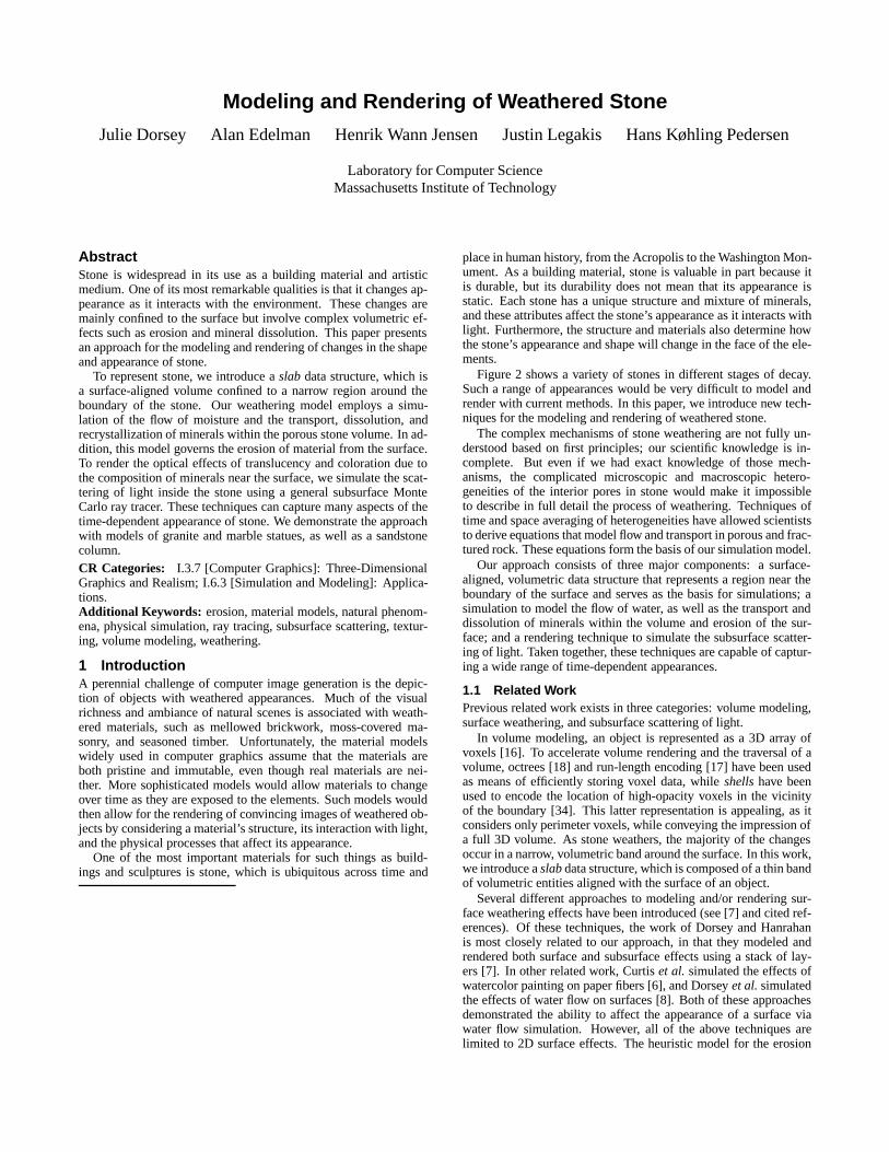
Figure 1 The mechanism of weathering. After a new stone (a) hasbeen exposed to the weather, it comes under attack by oxides thatform a solution with rainwater (b). The solution penetrates into thestone and by recrystallization forms a crust (c). If parts of the crusterode (d), new stone is left open to further chemical attack.
off, they carry away with them constituents of the stone, leavingfresh stone open to further chemical attack. Areas that retain watertend to break off first. Thus, horizontal or inclined surfaces erodemore rapidly than vertical surfaces [25]. Figure 1 is a schematicdiagram of the weathering process.
The net effects of weathering, then, are the formation of dirtycrusts, the wearing away of the stone surfaces, and, above all, theloss by the aging stone of its capacity to resist decay. Weatheringproduces a graded zone in which the properties nearest the surfaceare altered the most and those farthest from the surface resemblethe properties of unweathered stone [1].
The basic processes involved in stone weathering are the travelof moisture, dissolution and recrystallization of minerals, chemicaltransformation of minerals, and deposition of atmospheric pollu-tants. These factors are described in more detail below.
• Travel of moisture: Among the various elements involved instone weathering, water is the most critical. As stone is aporous material, water is absorbed into the material by capil-lary pressure and then evaporated back to the surface. Theflow of water over a stone surface also plays a role in theweathering of stone. However, in this work, we focus on mod-eling the movement of water within the stone itself, which isthe principal cause of stone decay [1]. We do, however, modelthe net effect of the flow of water on the surface using a simpleprobabilistic approach. Given the time scales in which stoneweathering occurs, this gives a reasonable approximation.
• Dissolution and recrystallization of minerals: When the min-erals and salts that constitute stone come into contact withmoisture, they begin to dissolve. The rate of dissolution variesgreatly depending on the type of mineral, although it is alwaysvery slow by human standards. In general, stones composedof fine grains, such as sandstone, weather more quickly thanthose with larger grains. As the water evaporates, these dis-solved minerals recrystallize.
• Chemical transformation of minerals: All minerals occurringin stone undergo a continuous process that transforms theminto less durable minerals, and eventually into clay. This pro-cess results in changes in the appearance, such as fading, in-creased roughness, and oxidation of iron traces.
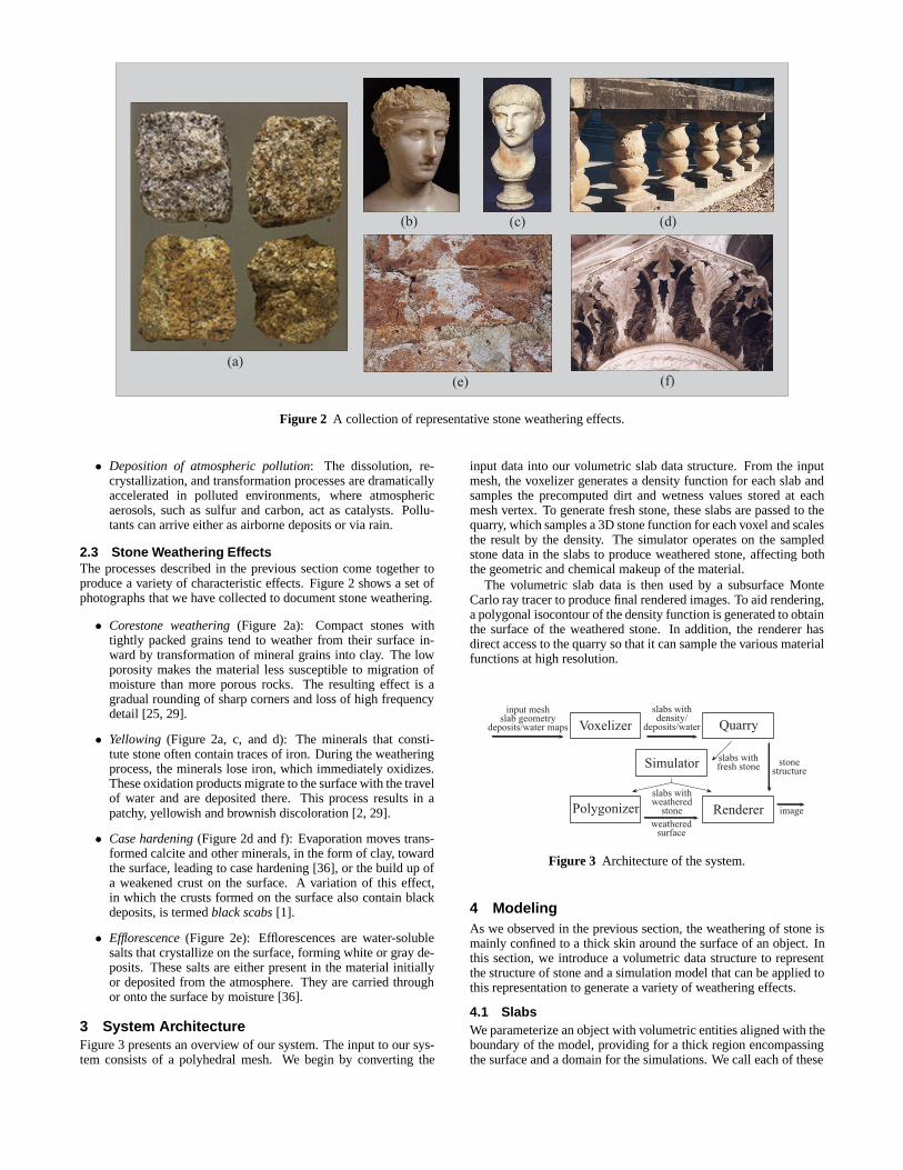
Figure 2 A collection of representative stone weathering effects.
• Deposition of atmospheric pollution: The dissolution, re-crystallization, and transformation processes are dramaticallyaccelerated in polluted environments, where atmosphericaerosols, such as sulfur and carbon, act as catalysts. Pollu-tants can arrive either as airborne deposits or via rain.
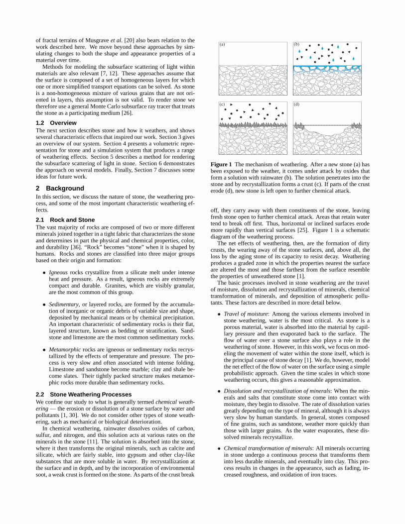
2.3 Stone Weathering EffectsThe processes described in the previous section come together toproduce a variety of characteristic effects. Figure 2 shows a set ofphotographs that we have collected to document stone weathering.
• Corestone weathering(Figure 2a): Compact stones withtightly packed grains tend to weather from their surface in-ward by transformation of mineral grains into clay. The lowporosity makes the material less susceptible to migration ofmoisture than more porous rocks. The resulting effect is agradual rounding of sharp corners and loss of high frequencydetail [25, 29].
• Yellowing (Figure 2a, c, and d): The minerals that consti-tute stone often contain traces of iron. During the weatheringprocess, the minerals lose iron, which immediately oxidizes.These oxidation products migrate to the surface with the travelof water and are deposited there. This process results in apatchy, yellowish and brownish discoloration [2, 29].
• Case hardening(Figure 2d and f): Evaporation moves trans-formed calcite and other minerals, in the form of clay, towardthe surface, leading to case hardening [36], or the build up ofa weakened crust on the surface. A variation of this effect,in which the crusts formed on the surface also contain blackdeposits, is termedblack scabs[1].
• Efflorescence(Figure 2e): Efflorescences are water-solublesalts that crystallize on the surface, forming white or gray de-posits. These salts are either present in the material initiallyor deposited from the atmosphere. They are carried throughor onto the surface by moisture [36].
3 System ArchitectureFigure 3 presents an overview of our system. The input to our sys-tem consists of a polyhedral mesh. We begin by converting the
input data into our volumetric slab data structure. From the inputmesh, the voxelizer generates a density function for each slab andsamples the precomputed dirt and wetness values stored at eachmesh vertex. To generate fresh stone, these slabs are passed to thequarry, which samples a 3D stone function for each voxel and scalesthe result by the density. The simulator operates on the sampledstone data in the slabs to produce weathered stone, affecting boththe geometric and chemical makeup of the material.
The volumetric slab data is then used by a subsurface MonteCarlo ray tracer to produce final rendered images. To aid rendering,a polygonal isocontour of the density function is generated to obtainthe surface of the weathered stone. In addition, the renderer hasdirect access to the quarry so that it can sample the various materialfunctions at high resolution.
Figure 3 Architecture of the system.
4 ModelingAs we observed in the previous section, the weathering of stone ismainly confined to a thick skin around the surface of an object. Inthis section, we introduce a volumetric data structure to representthe structure of stone and a simulation model that can be applied tothis representation to generate a variety of weathering effects.
4.1 SlabsWe parameterize an object with volumetric entities aligned with theboundary of the model, providing for a thick region encompassingthe surface and a domain for the simulations. We call each of these
(a)
(b)
(c)
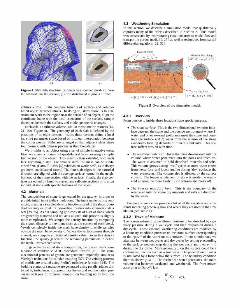
Figure 4 Slab data structure. (a) Slabs on a scanned mesh, (b) Wa-ter diffused into the surface, (c) Iron distributed in grains of mica.
entities aslab. Slabs combine benefits of surface- and volume-based object representations. In doing so, slabs allow us to con-strain our work to the region near the surface of an object, align thecoordinate frame with the local orientation of the surface, samplethe object beneath the surface, and model geometric changes.
Each slab is a trilinear volume, similar to volumetric textures [15,21] (see Figure 4). The geometry of each slab is defined by thepositions of its eight corners. Inside, these corners define a local(u, v, w) parameter space based on trilinear interpolation betweenthe corner points. Slabs are arranged so that adjacent slabs sharefour corners, with bilinear patches as their boundaries.
We fit slabs to an object using a set of simple interactive tools.First, we construct a mesh of quadrilateral faces covering a simpli-fied version of the object. This mesh is then extruded, with eachface becoming a slab. For smaller slabs, the mesh can be subdi-vided first. (Catmull-Clark [5] subdivision works well, as it alwaysproduces quadrilateral faces.) The four slab edges in the extrudeddirection are aligned with the average surface normal in the neigh-borhood of their intersection with the surface. Finally, the slab ver-tices are edited by hand, to correct any self-intersections or to alignindividual slabs with specific features of the object.
4.2 MaterialsThe composition of stone is generated by thequarry, in order toprovide initial input to the simulations. The input model is first vox-elized, creating a sampled density function stored in the slabs. Stan-dard techniques exist for converting meshes into volumetric datasets [28, 35]. As our sampling grid consists of a set of slabs, whichare generally distorted and not axis-aligned, this process is slightlymore complicated. We sample the density function by computingthe signed distance to the input mesh at the corners of each voxel.Voxels completely inside the mesh have density 1, while samplesoutside the mesh have density 0. Where the surface passes througha voxel, we compute a fractional density value. Given this densityfunction, the quarry generates the remaining parameters to definethe fresh, unweathered stone.
To generate the initial stone composition, the quarry uses a com-bination of standard solid 3D procedural textures [10]. The gran-ular mineral patterns of granite are generated implicitly, similar toWorley’s technique for cellular texturing [37]. The veining patternsof marble are created using Perlin’s turbulence function [24]. Thebedding planes of sandstone are generated using parallel planes dis-torted by turbulence, to approximate the natural sedimentation pro-cesses of layers of different composition building up to form thestone.
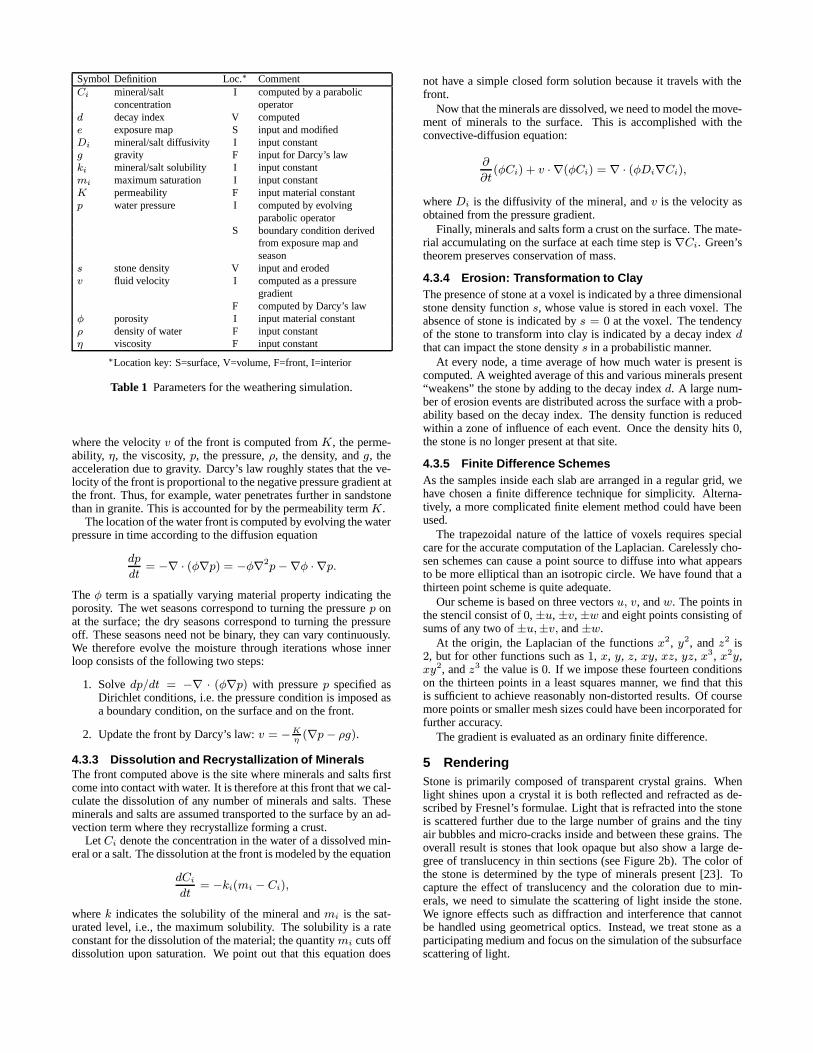
4.3 Weathering SimulationIn this section, we describe a simulation model that qualitativelycaptures many of the effects described in Section 2. This modelwas constructed by incorporating equations used to model flow andtransport in porous media [9, 27], as well as techniques from partialdifferential equations [32, 33].
p
Figure 5 Overview of the simulation model.
4.3.1 OverviewFrom outside to inside, three locations have special purpose:
• The stone surface: This is the two dimensional exterior inter-face between the stone and the outside environment where 1)water and other external pollutants meet the stone and pene-trate the surface and 2) water from the interior of the stoneevaporates forming deposits of minerals and salts. This sur-face suffers erosion with time.
• The weathered interior: This is the three dimensional interiorvolume where water penetrates into the pores and fractures.The water is assumed to hold dissolved minerals and salts.This volume grows during “wet” cycles as more water entersfrom the surface, and it gets smaller during “dry” cycles as thewater evaporates. The volume also is affected by the surfaceerosion. The longer an element of stone is inside the weath-ered interior, the more likely it is to weaken and break off.
• The interior moist/dry front: This is the boundary of theweathered interior where dry minerals and salts are dissolvedby the water.
For easy reference, we provide a list of all the variables and con-stants indicating precisely how and where they are used in the sim-ulation (see Table 1).
4.3.2 Travel of MoistureThe porous nature of stone allows moisture to be absorbed by cap-illary pressure during a wet cycle and then evaporated during adry cycle. These external weathering conditions are modeled bya boundary condition pressure on the stone surface correspondingto the “push” of the water on this surface. In our simulations, wealternate between wet cycles and dry cycles by settingp accordingto the surface wetness map during the wet cycle and thenp = 0during the dry cycle. More generallyp on the surface could be acontinuous function such as a sine wave. The penetration of wateris simulated by a front below the surface. The boundary conditionthere is alwaysp = 0. The further the water penetrates, the morevolume that becomes weakened and weathered. The front movesaccording to Darcy’s law
v = −K
η(∇p− ρg),
Symbol Definition Loc.∗ CommentCi mineral/salt I computed by a parabolic
concentration operatord decay index V computede exposure map S input and modifiedDi mineral/salt diffusivity I input constantg gravity F input for Darcy’s lawki mineral/salt solubility I input constantmi maximum saturation I input constantK permeability F input material constantp water pressure I computed by evolving
parabolic operatorS boundary condition derived
from exposure map andseason
s stone density V input and erodedv fluid velocity I computed as a pressure
gradientF computed by Darcy’s law
φ porosity I input material constantρ density of water F input constantη viscosity F input constant
∗Location key: S=surface, V=volume, F=front, I=interior
Table 1 Parameters for the weathering simulation.
where the velocityv of the front is computed fromK, the perme-ability, η, the viscosity,p, the pressure,ρ, the density, andg, theacceleration due to gravity. Darcy’s law roughly states that the ve-locity of the front is proportional to the negative pressure gradient atthe front. Thus, for example, water penetrates further in sandstonethan in granite. This is accounted for by the permeability termK.
The location of the water front is computed by evolving the waterpressure in time according to the diffusion equation
dp
dt= −∇ · (φ∇p) = −φ∇2p−∇φ · ∇p.
Theφ term is a spatially varying material property indicating theporosity. The wet seasons correspond to turning the pressurep onat the surface; the dry seasons correspond to turning the pressureoff. These seasons need not be binary, they can vary continuously.We therefore evolve the moisture through iterations whose innerloop consists of the following two steps:
1. Solvedp/dt = −∇ · (φ∇p) with pressurep specified asDirichlet conditions, i.e. the pressure condition is imposed asa boundary condition, on the surface and on the front.
2. Update the front by Darcy’s law:v = −Kη
(∇p− ρg).
4.3.3 Dissolution and Recrystallization of MineralsThe front computed above is the site where minerals and salts firstcome into contact with water. It is therefore at this front that we cal-culate the dissolution of any number of minerals and salts. Theseminerals and salts are assumed transported to the surface by an ad-vection term where they recrystallize forming a crust.
LetCi denote the concentration in the water of a dissolved min-eral or a salt. The dissolution at the front is modeled by the equation
dCi
dt= −ki(mi − Ci),
wherek indicates the solubility of the mineral andmi is the sat-urated level, i.e., the maximum solubility. The solubility is a rateconstant for the dissolution of the material; the quantitymi cuts offdissolution upon saturation. We point out that this equation does
not have a simple closed form solution because it travels with thefront.
Now that the minerals are dissolved, we need to model the move-ment of minerals to the surface. This is accomplished with theconvective-diffusion equation:
∂
∂t(φCi) + v · ∇(φCi) = ∇ · (φDi∇Ci),
whereDi is the diffusivity of the mineral, andv is the velocity asobtained from the pressure gradient.
Finally, minerals and salts form a crust on the surface. The mate-rial accumulating on the surface at each time step is∇Ci. Green’stheorem preserves conservation of mass.
4.3.4 Erosion: Transformation to ClayThe presence of stone at a voxel is indicated by a three dimensionalstone density functions, whose value is stored in each voxel. Theabsence of stone is indicated bys = 0 at the voxel. The tendencyof the stone to transform into clay is indicated by a decay indexdthat can impact the stone densitys in a probabilistic manner.
At every node, a time average of how much water is present iscomputed. A weighted average of this and various minerals present“weakens” the stone by adding to the decay indexd. A large num-ber of erosion events are distributed across the surface with a prob-ability based on the decay index. The density function is reducedwithin a zone of influence of each event. Once the density hits0,the stone is no longer present at that site.
4.3.5 Finite Difference SchemesAs the samples inside each slab are arranged in a regular grid, wehave chosen a finite difference technique for simplicity. Alterna-tively, a more complicated finite element method could have beenused.
The trapezoidal nature of the lattice of voxels requires specialcare for the accurate computation of the Laplacian. Carelessly cho-sen schemes can cause a point source to diffuse into what appearsto be more elliptical than an isotropic circle. We have found that athirteen point scheme is quite adequate.
Our scheme is based on three vectorsu, v, andw. The points inthe stencil consist of0,±u,±v,±w and eight points consisting ofsums of any two of±u,±v, and±w.
At the origin, the Laplacian of the functionsx2, y2, andz2 is2, but for other functions such as1, x, y, z, xy, xz, yz, x3, x2y,xy2, andz3 the value is0. If we impose these fourteen conditionson the thirteen points in a least squares manner, we find that thisis sufficient to achieve reasonably non-distorted results. Of coursemore points or smaller mesh sizes could have been incorporated forfurther accuracy.
The gradient is evaluated as an ordinary finite difference.
5 RenderingStone is primarily composed of transparent crystal grains. Whenlight shines upon a crystal it is both reflected and refracted as de-scribed by Fresnel’s formulae. Light that is refracted into the stoneis scattered further due to the large number of grains and the tinyair bubbles and micro-cracks inside and between these grains. Theoverall result is stones that look opaque but also show a large de-gree of translucency in thin sections (see Figure 2b). The color ofthe stone is determined by the type of minerals present [23]. Tocapture the effect of translucency and the coloration due to min-erals, we need to simulate the scattering of light inside the stone.We ignore effects such as diffraction and interference that cannotbe handled using geometrical optics. Instead, we treat stone as aparticipating medium and focus on the simulation of the subsurfacescattering of light.
5.1 Subsurface Scattering in StoneLight transport in a participating medium is described by the fol-lowing integral-equation [31]:
L(x, ~ω) =
∫ x
xe
τ (x′, x)σ(x′)
∫Ω
f(x′, ~ω′, ~ω)L(x′, ~ω′) dω′ dx′ +
τ (xe, x)L(xe, ~ω) , (1)
whereL(x, ~ω) is the radiance atx in the direction~ω, σ(x) is thescattering coefficient,f(x, ~ω′, ~ω) is the phase-function describinghow light is scattered in different directions, andxe is the end pointof the medium. The transmittanceτ (x′, x) from x′ to x is given by
τ (x′, x) = e−∫x
x′κ(ξ) dξ
, (2)
whereκ(ξ) is the extinction coefficient.The phase-functionf describes how light is scattered within the
stone. Since the cracks and air bubbles are larger than the wave-length of light, the type of scattering is described by Mie theory [3].To simulate the combined effect of back-scattering and forward-scattering, we use the two-lobed Schlick-approximation [4] of theempirical Henyey-Greenstein phase-function [13], which is a goodapproximation of Mie scattering.
To simulate subsurface scattering in stone, we need to applya method that can handle the extreme optical thickness of cer-tain stone minerals, such as mica. If we add to this the non-homogeneous media and the non-diffuse phase-function, then it be-comes clear that only a method based on Monte Carlo ray tracingwill work. We use a variant of the photon map method in whicha volume photon map is used to capture the in-scattered light in aparticipating medium [14].
The volume photon map is generated by emitting photons fromthe light sources in the scene and storing them as they scatter insidethe stone. We only store photons representing the indirect light; thedirect light is computed using standard ray tracing techniques.
The rendering method for the stone medium has been integratedin a Monte Carlo based ray tracer. Whenever a ray enters a stonemedium it is decided whether the ray interacts with the medium orcontinues through the medium. The probability of a ray interact-ing with medium is given by the following cumulative probabilitydensity function:
P (xs) = 1− e−∫xs
xκ(x′) dx′
. (3)
As stone is non-homogeneous, we use ray marching to computethe value of the integral in this equation. In practice this worksby selecting a uniformly distributed random number0 < ξ < 1and computing
∫ xsxκ(x′) dx′ using ray marching until it equals
− log ξ or until the back of the stone is reached. If the back ofthe stone is reached it means that no scattering event happened andthe ray is traced through the stone. Otherwise a scattering eventhappened atxs, and we must compute the radianceLs scatteredin the direction~ωt of the ray at this point. For the extreme opticalthickness in stone, this approach is significantly more efficient thanthe ray marching approach used in [14].
The scattered radianceLs(x, ~ω) is computed as the sum of out-scattered radiance due to direct illuminationLd and indirect illumi-nationLi:
Ls(x, ~ω) = Ld(x, ~ω) + Li(x, ~ω) . (4)
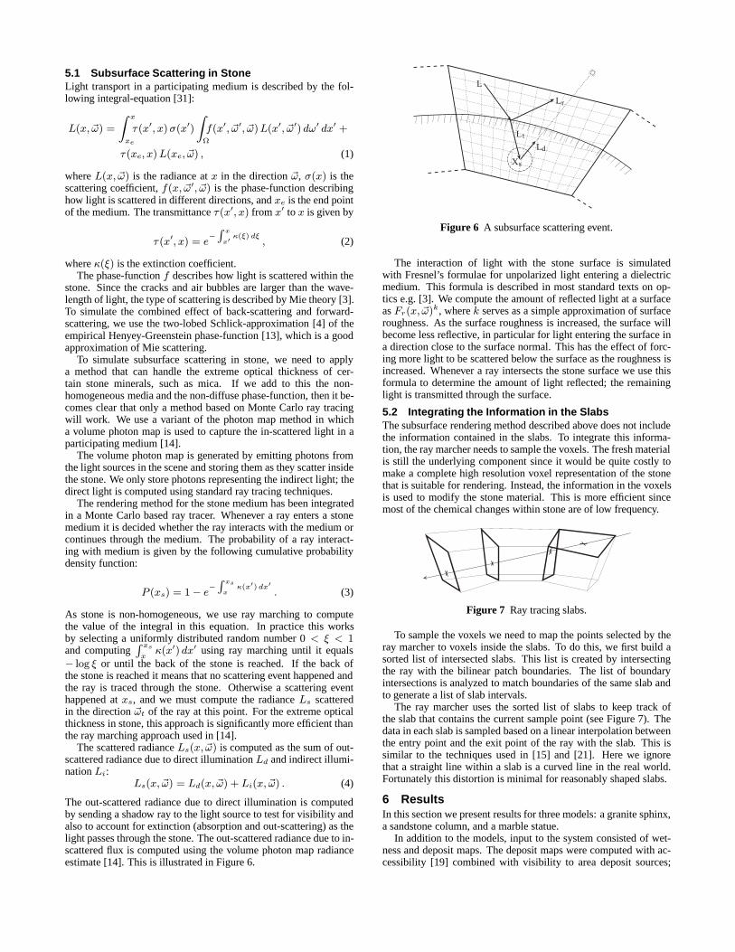
The out-scattered radiance due to direct illumination is computedby sending a shadow ray to the light source to test for visibility andalso to account for extinction (absorption and out-scattering) as thelight passes through the stone. The out-scattered radiance due to in-scattered flux is computed using the volume photon map radianceestimate [14]. This is illustrated in Figure 6.
Figure 6 A subsurface scattering event.
The interaction of light with the stone surface is simulatedwith Fresnel’s formulae for unpolarized light entering a dielectricmedium. This formula is described in most standard texts on op-tics e.g. [3]. We compute the amount of reflected light at a surfaceasFr(x, ~ω)k, wherek serves as a simple approximation of surfaceroughness. As the surface roughness is increased, the surface willbecome less reflective, in particular for light entering the surface ina direction close to the surface normal. This has the effect of forc-ing more light to be scattered below the surface as the roughness isincreased. Whenever a ray intersects the stone surface we use thisformula to determine the amount of light reflected; the remaininglight is transmitted through the surface.
5.2 Integrating the Information in the SlabsThe subsurface rendering method described above does not includethe information contained in the slabs. To integrate this informa-tion, the ray marcher needs to sample the voxels. The fresh materialis still the underlying component since it would be quite costly tomake a complete high resolution voxel representation of the stonethat is suitable for rendering. Instead, the information in the voxelsis used to modify the stone material. This is more efficient sincemost of the chemical changes within stone are of low frequency.
Figure 7 Ray tracing slabs.
To sample the voxels we need to map the points selected by theray marcher to voxels inside the slabs. To do this, we first build asorted list of intersected slabs. This list is created by intersectingthe ray with the bilinear patch boundaries. The list of boundaryintersections is analyzed to match boundaries of the same slab andto generate a list of slab intervals.
The ray marcher uses the sorted list of slabs to keep track ofthe slab that contains the current sample point (see Figure 7). Thedata in each slab is sampled based on a linear interpolation betweenthe entry point and the exit point of the ray with the slab. This issimilar to the techniques used in [15] and [21]. Here we ignorethat a straight line within a slab is a curved line in the real world.Fortunately this distortion is minimal for reasonably shaped slabs.
6 ResultsIn this section we present results for three models: a granite sphinx,a sandstone column, and a marble statue.
In addition to the models, input to the system consisted of wet-ness and deposit maps. The deposit maps were computed with ac-cessibility [19] combined with visibility to area deposit sources;
(a) (b)
(c) (d)
Figure 8 Granite sphinx.
wetness maps were computed with visibility to a directional rainsource.
All simulations were run on a quad 250 MHz R10000 SGI ma-chine, and renderings were computed using a dual 400 MHz Pen-tium II PC running Linux. Images were rendered with global illu-mination at a resolution of 1024 in the larger dimension, with foursamples per pixel.
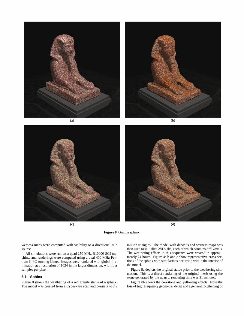
6.1 SphinxFigure 8 shows the weathering of a red granite statue of a sphinx.The model was created from a Cyberware scan and consists of 2.2
million triangles. The model with deposits and wetness maps wasthen used to initialize 281 slabs, each of which contains323 voxels.The weathering effects in this sequence were created in approxi-mately 24 hours. Figure 4s b and c show representative cross sec-tions of the sphinx with simulations occurring within the interior ofthe model.
Figure 8a depicts the original statue prior to the weathering sim-ulation. This is a direct rendering of the original mesh using thestone generated by the quarry; rendering time was 31 minutes.
Figure 8b shows the corestone and yellowing effects. Note theloss of high frequency geometric detail and a general roughening of
(a) (b) (c) (d)
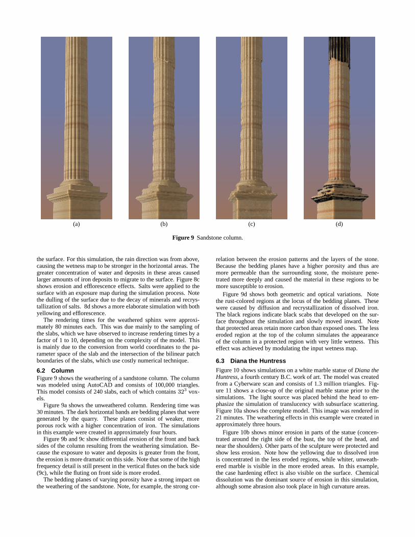
Figure 9 Sandstone column.
the surface. For this simulation, the rain direction was from above,causing the wetness map to be stronger in the horizontal areas. Thegreater concentration of water and deposits in these areas causedlarger amounts of iron deposits to migrate to the surface. Figure 8cshows erosion and efflorescence effects. Salts were applied to thesurface with an exposure map during the simulation process. Notethe dulling of the surface due to the decay of minerals and recrys-tallization of salts. 8d shows a more elaborate simulation with bothyellowing and efflorescence.
The rendering times for the weathered sphinx were approxi-mately 80 minutes each. This was due mainly to the sampling ofthe slabs, which we have observed to increase rendering times by afactor of 1 to 10, depending on the complexity of the model. Thisis mainly due to the conversion from world coordinates to the pa-rameter space of the slab and the intersection of the bilinear patchboundaries of the slabs, which use costly numerical technique.
6.2 ColumnFigure 9 shows the weathering of a sandstone column. The columnwas modeled using AutoCAD and consists of 100,000 triangles.This model consists of 240 slabs, each of which contains323 vox-els.
Figure 9a shows the unweathered column. Rendering time was30 minutes. The dark horizontal bands are bedding planes that weregenerated by the quarry. These planes consist of weaker, moreporous rock with a higher concentration of iron. The simulationsin this example were created in approximately four hours.
Figure 9b and 9c show differential erosion of the front and backsides of the column resulting from the weathering simulation. Be-cause the exposure to water and deposits is greater from the front,the erosion is more dramatic on this side. Note that some of the highfrequency detail is still present in the vertical flutes on the back side(9c), while the fluting on front side is more eroded.
The bedding planes of varying porosity have a strong impact onthe weathering of the sandstone. Note, for example, the strong cor-
relation between the erosion patterns and the layers of the stone.Because the bedding planes have a higher porosity and thus aremore permeable than the surrounding stone, the moisture pene-trated more deeply and caused the material in these regions to bemore susceptible to erosion.
Figure 9d shows both geometric and optical variations. Notethe rust-colored regions at the locus of the bedding planes. Thesewere caused by diffusion and recrystallization of dissolved iron.The black regions indicate black scabs that developed on the sur-face throughout the simulation and slowly moved inward. Notethat protected areas retain more carbon than exposed ones. The lesseroded region at the top of the column simulates the appearanceof the column in a protected region with very little wetness. Thiseffect was achieved by modulating the input wetness map.
6.3 Diana the Huntress
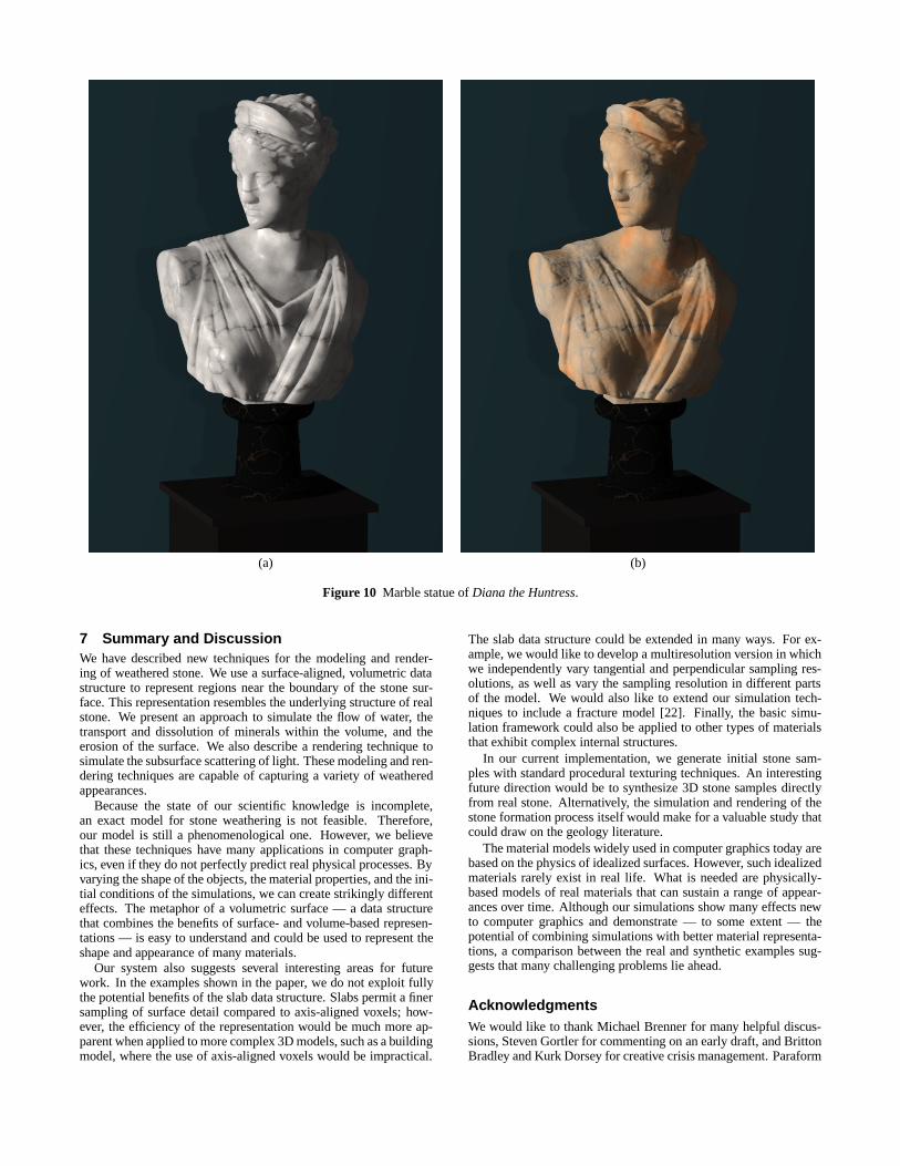
Figure 10 shows simulations on a white marble statue ofDiana theHuntress, a fourth century B.C. work of art. The model was createdfrom a Cyberware scan and consists of 1.3 million triangles. Fig-ure 11 shows a close-up of the original marble statue prior to thesimulations. The light source was placed behind the head to em-phasize the simulation of translucency with subsurface scattering.Figure 10a shows the complete model. This image was rendered in21 minutes. The weathering effects in this example were created inapproximately three hours.
Figure 10b shows minor erosion in parts of the statue (concen-trated around the right side of the bust, the top of the head, andnear the shoulders). Other parts of the sculpture were protected andshow less erosion. Note how the yellowing due to dissolved ironis concentrated in the less eroded regions, while whiter, unweath-ered marble is visible in the more eroded areas. In this example,the case hardening effect is also visible on the surface. Chemicaldissolution was the dominant source of erosion in this simulation,although some abrasion also took place in high curvature areas.
(a) (b)
Figure 10 Marble statue ofDiana the Huntress.
7 Summary and DiscussionWe have described new techniques for the modeling and render-ing of weathered stone. We use a surface-aligned, volumetric datastructure to represent regions near the boundary of the stone sur-face. This representation resembles the underlying structure of realstone. We present an approach to simulate the flow of water, thetransport and dissolution of minerals within the volume, and theerosion of the surface. We also describe a rendering technique tosimulate the subsurface scattering of light. These modeling and ren-dering techniques are capable of capturing a variety of weatheredappearances.
Because the state of our scientific knowledge is incomplete,an exact model for stone weathering is not feasible. Therefore,our model is still a phenomenological one. However, we believethat these techniques have many applications in computer graph-ics, even if they do not perfectly predict real physical processes. Byvarying the shape of the objects, the material properties, and the ini-tial conditions of the simulations, we can create strikingly differenteffects. The metaphor of a volumetric surface — a data structurethat combines the benefits of surface- and volume-based represen-tations — is easy to understand and could be used to represent theshape and appearance of many materials.
Our system also suggests several interesting areas for futurework. In the examples shown in the paper, we do not exploit fullythe potential benefits of the slab data structure. Slabs permit a finersampling of surface detail compared to axis-aligned voxels; how-ever, the efficiency of the representation would be much more ap-parent when applied to more complex 3D models, such as a buildingmodel, where the use of axis-aligned voxels would be impractical.
The slab data structure could be extended in many ways. For ex-ample, we would like to develop a multiresolution version in whichwe independently vary tangential and perpendicular sampling res-olutions, as well as vary the sampling resolution in different partsof the model. We would also like to extend our simulation tech-niques to include a fracture model [22]. Finally, the basic simu-lation framework could also be applied to other types of materialsthat exhibit complex internal structures.
In our current implementation, we generate initial stone sam-ples with standard procedural texturing techniques. An interestingfuture direction would be to synthesize 3D stone samples directlyfrom real stone. Alternatively, the simulation and rendering of thestone formation process itself would make for a valuable study thatcould draw on the geology literature.
The material models widely used in computer graphics today arebased on the physics of idealized surfaces. However, such idealizedmaterials rarely exist in real life. What is needed are physically-based models of real materials that can sustain a range of appear-ances over time. Although our simulations show many effects newto computer graphics and demonstrate — to some extent — thepotential of combining simulations with better material representa-tions, a comparison between the real and synthetic examples sug-gests that many challenging problems lie ahead.
AcknowledgmentsWe would like to thank Michael Brenner for many helpful discus-sions, Steven Gortler for commenting on an early draft, and BrittonBradley and Kurk Dorsey for creative crisis management. Paraform
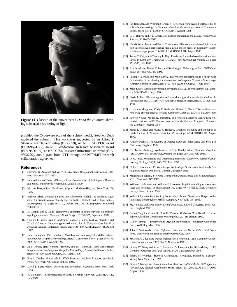
Figure 11 Closeup of the unweatheredDiana the Huntressshow-ing subsurface scattering of light.
provided the Cyberware scan of the Sphinx model; Stephen Duckmodeled the column. This work was supported by an Alfred P.Sloan Research Fellowship (BR-3659), an NSF CAREER award(CCR-9624172), an NSF Postdoctoral Research Associates award(EIA-9806139), an NSF CISE Research Infrastructure award (EIA-9802220), and a grant from NTT through the NTT/MIT researchcollaboration agreement.
References[1] Giovanni G. Amoroso and Vasco Fassina.Stone Decay and Conservation. Else-
vier, New York, NY, 1983.
[2] John Ashurst and Francis Dimes, editors.Conservation of Building and Decora-tive Stone. Butterworth-Heinemann, London, 1990.
[3] Michael Bass, editor.Handbook of Optics. McGraw-Hill, Inc., New York, NY,1995.
[4] Philippe Blasi, Bertrand Le Saec, and Christophe Schlick. A rendering algo-rithm for discrete volume density objects. In R. J. Hubbold and R. Juan, editors,Eurographics ’93, pages 201–210, Oxford, UK, 1993. Eurographics, BlackwellPublishers.
[5] E. Catmull and J. Clark. Recursively generated B-spline surfaces on arbitrarytopological meshes.Computer-Aided Design, 10:350–355, September 1978.
[6] Cassidy J. Curtis, Sean E. Anderson, Joshua E. Seims, Kurt W. Fleischer, andDavid H. Salesin. Computer-generated watercolor. InComputer Graphics Pro-ceedings, Annual Conference Series, pages 421–430. ACM SIGGRAPH, August1997.
[7] Julie Dorsey and Pat Hanrahan. Modeling and rendering of metallic patinas.In Computer Graphics Proceedings, Annual Conference Series, pages 387–396.ACM SIGGRAPH, August 1996.
[8] Julie Dorsey, Hans Køhling Pedersen, and Pat Hanrahan. Flow and changesin appearance. InComputer Graphics Proceedings, Annual Conference Series,pages 411–420. ACM SIGGRAPH, August 1996.
[9] F. A. L. Dullien. Porous Media: Fluid Transport and Pore Structure. AcademicPress, New York, NY, second edition, 1992.
[10] David S. Ebert, editor.Texturing and Modeling. Academic Press, New York,1994.
[11] K. Lal Gauri. The preservation of stone.Scientific American, 238(6):126–136,June 1978.
[12] Pat Hanrahan and Wolfgang Krueger. Reflection from layered surfaces due tosubsurface scattering. InComputer Graphics Proceedings, Annual ConferenceSeries, pages 165–174. ACM SIGGRAPH, August 1993.
[13] L. G. Henyey and J. L. Greenstein. Diffuse radiation in the galaxy.AstrophysicsJournal, 93:70–83, 1941.
[14] Henrik Wann Jensen and Per H. Christensen. Efficient simulation of light trans-port in scenes with participating media using photon maps. InComputer Graph-ics Proceedings, pages 311–320. ACM SIGGRAPH, August 1998.
[15] James T. Kajiya and Timothy L. Kay. Rendering fur with three dimensional tex-tures. InComputer Graphics (SIGGRAPH ’89 Proceedings), volume 23, pages271–280, July 1989.
[16] Arie Kaufman, Daniel Cohen, and Roni Yagel. Volume graphics.IEEE Com-puter, 26(7):51–64, July 1993.
[17] Philippe Lacroute and Marc Levoy. Fast volume rendering using a shear–warpfactorization of the viewing transformation. InComputer Graphics Proceedings,Annual Conference Series, pages 451–458. ACM SIGGRAPH, July 1994.
[18] Marc Levoy. Efficient ray tracing of volume data.ACM Transactions on Graph-ics, 9(3):245–261, July 1990.
[19] Gavin Miller. Efficient algorithms for local and global accessibility shading. InProceedings of SIGGRAPH ’94, Annual Conference Series, pages 319–326, July1994.
[20] F. Kenton Musgrave, Craig E. Kolb, and Robert S. Mace. The synthesis andrendering of eroded fractal terrains.Computer Graphics, 23(3):41–50, July 1989.
[21] Fabrice Neyret. Modeling, animating, and rendering complex scenes using vol-umetric textures.IEEE Transactions on Visualization and Computer Graphics,4(1), January – March 1998.
[22] James F. O’Brien and Jessica K. Hodgins. Graphical modeling and animation ofbrittle fracture. InComputer Graphics Proceedings. ACM SIGGRAPH, August1999.
[23] Andrew Peckett.The Colours of Opaque Minerals. John Wiley and Sons Ltd,Chichester, England, 1992.
[24] Ken Perlin. An image synthesizer. In B. A. Barsky, editor,Computer Graphics(SIGGRAPH ’85 Proceedings), volume 19, pages 287–296, July 1985.
[25] D. G. Price. Weathering and weathering processes.Quarterly Journal of Engi-neering Geology, 16(28):243–252, June 1995.
[26] Holly E. Rushmeier.Realistic Image Synthesis for Scenes with Radiatively Par-ticipating Media. Phd thesis, Cornell University, 1988.
[27] Muhammad Sahimi.Flow and Transport in Porous Media and Fractured Rock.VCH, New York, NY, 1995.
[28] William J. Schroeder and William E. Lorensen. Implicit modeling of swept sur-faces and volumes. InVisualization ’94, pages 40–45. IEEE, IEEE ComputerSociety Press, October 1994.
[29] Walter Schumann.Handbook of Rocks, Minerals, and Gemstones. HarperCollinsPublishers and Houghton Mifflin Company, New York, NY, 1993.
[30] M. J. Selby. Hillslope Materials and Processes. Oxford University Press, Ox-ford, England, 1993.
[31] Robert Siegel and John R. Howell.Thermal Radiation Heat Transfer. Hemi-sphere Publishing Corporation, Washington, D.C., 3rd edition, 1992.
[32] Gilbert Strang. Introduction to Applied Mathematics. Wellesley-CambridgePress, Wellesley, MA, 1986.
[33] John C. Strikwerda.Finite Difference Schemes and Partial Differential Equa-tions. Wadsworth and Brooks, Pacific Grove, CA, 1989.
[34] Jayaram K. Udupa and Dewey Odhner. Shell rendering.IEEE Computer Graph-ics and Applications, 13(6):58–67, November 1993.
[35] Sidney W. Wang and Arie E. Kaufman. Volume-sampled 3d modeling.IEEEComputer Graphics and Applications, 14:26–32, September 1994.
[36] Erhard M. Winkler. Stone in Architecture: Properties, Durablity. Springer-Verlag, New York, NY, 1997.
[37] Steven P. Worley. A cellular texture basis function. InSIGGRAPH 96 ConferenceProceedings, Annual Conference Series, pages 291–294. ACM SIGGRAPH,August 1996.