Embed Size (px)
Citation preview
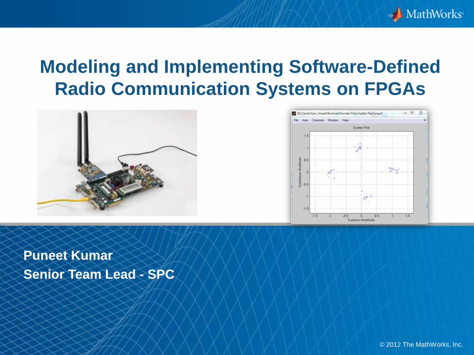
1© 2012 The MathWorks, Inc.
Modeling and Implementing Software-Defined
Radio Communication Systems on FPGAs
Puneet Kumar
Senior Team Lead - SPC
2
Agenda
Integrated Model-Based Design to Implement SDR on FPGA’s,
highlighting:
– Rapidly develop and verify a baseline transmitter and receiver using library
blocks
– Automatically generate HDL code and integrate the code with target hardware
– Verify the design using HDL cosimulation and FPGA-in-the-loop on an FPGA
Evaluation Kit
Q&A
3
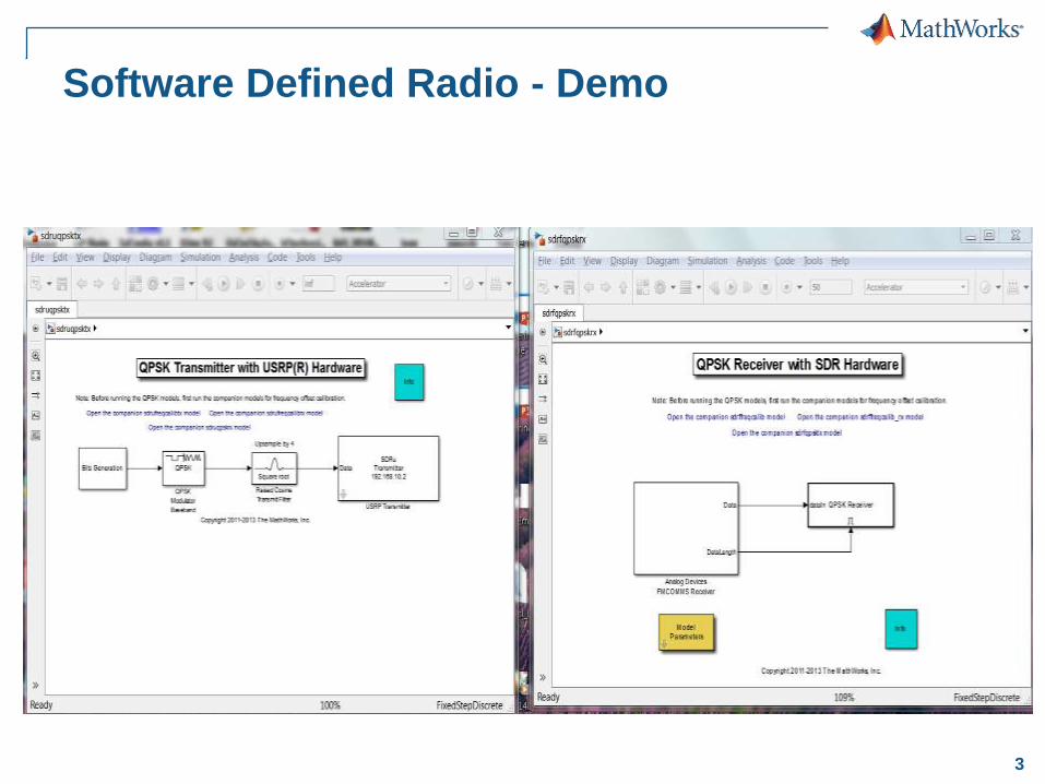
Software Defined Radio - Demo
4
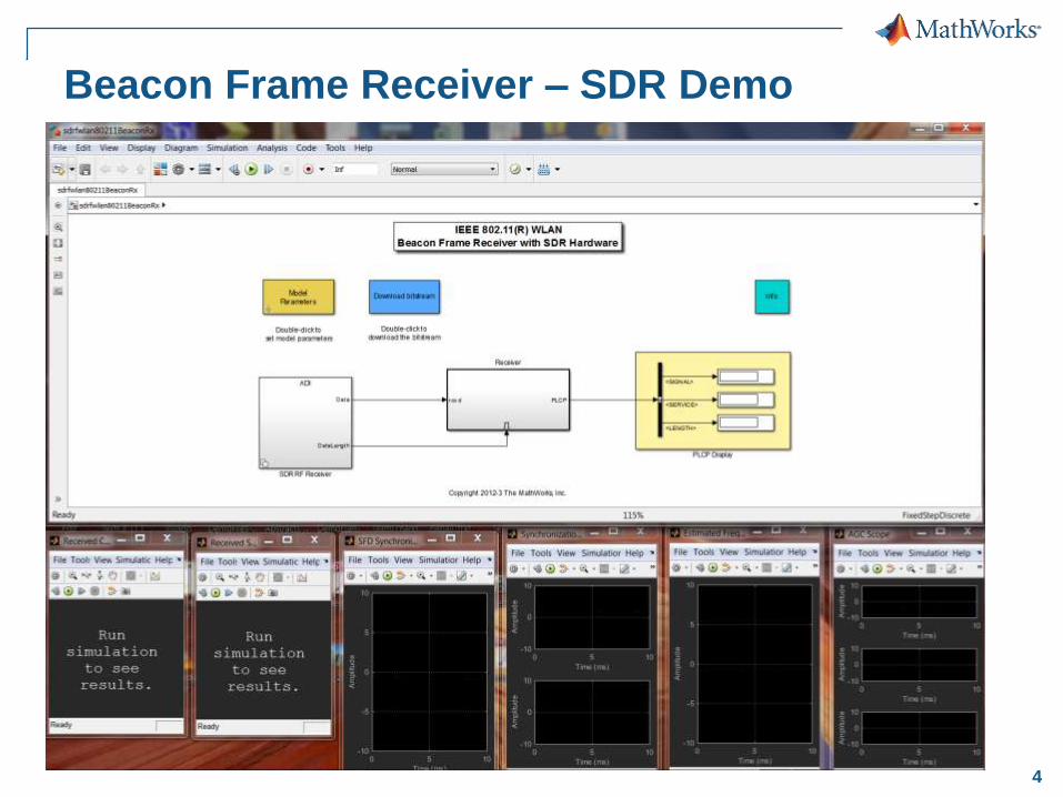
Beacon Frame Receiver – SDR Demo
5
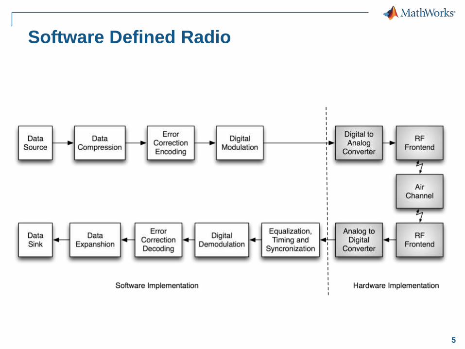
Software Defined Radio
6
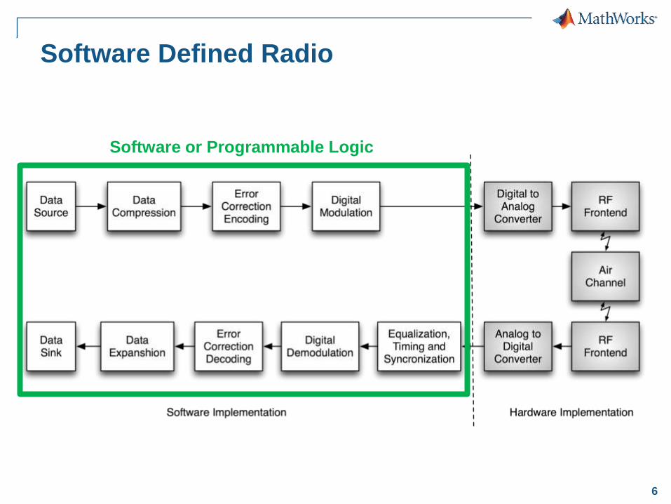
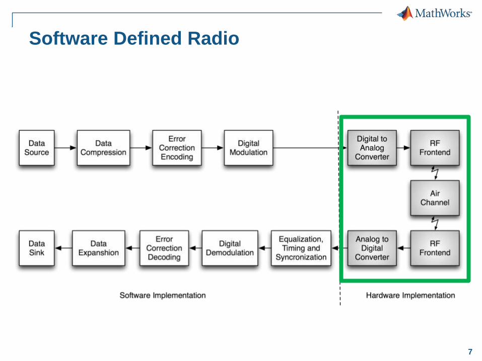
Software Defined Radio
Software or Programmable Logic
7
Software Defined Radio
8
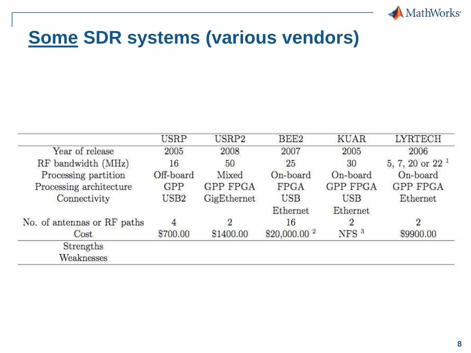
Some SDR systems (various vendors)
9
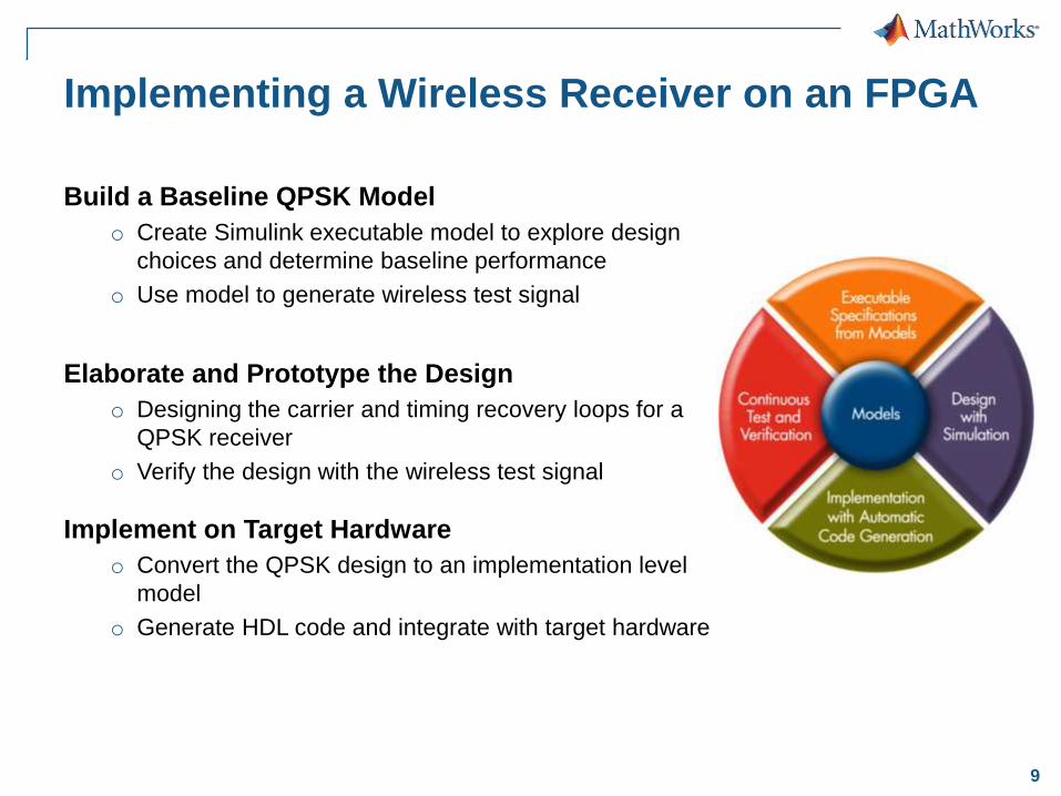
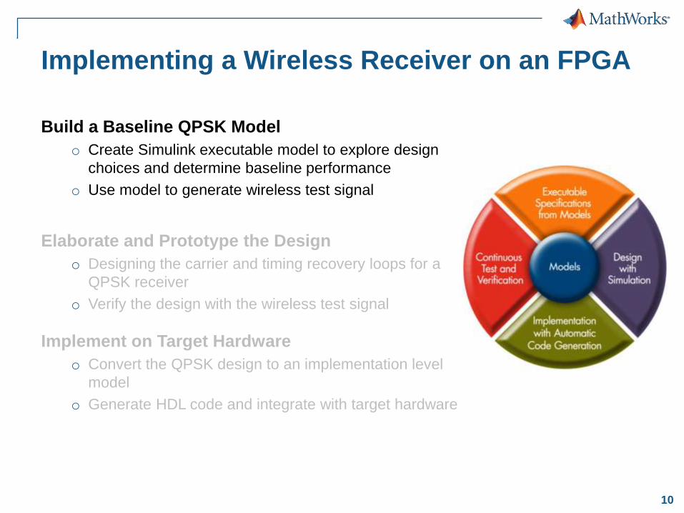
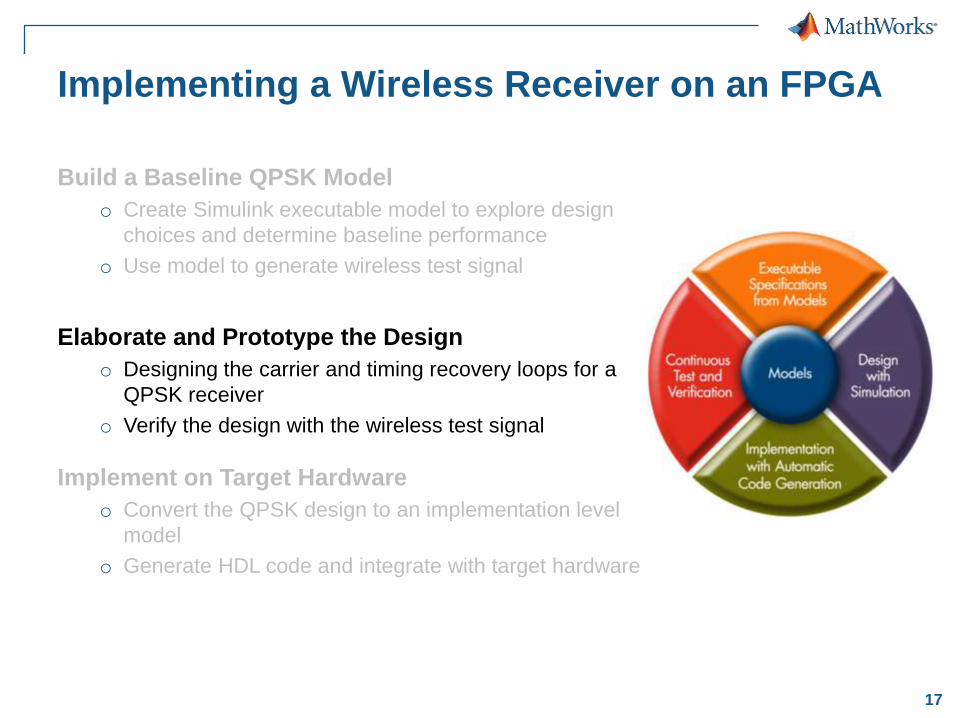
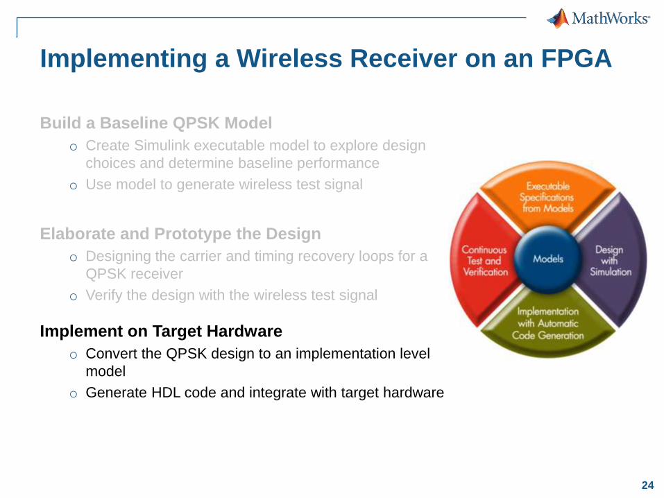
Implementing a Wireless Receiver on an FPGA
Build a Baseline QPSK Model
o Create Simulink executable model to explore design
choices and determine baseline performance
o Use model to generate wireless test signal
Elaborate and Prototype the Design
o Designing the carrier and timing recovery loops for a
QPSK receiver
o Verify the design with the wireless test signal
Implement on Target Hardware
o Convert the QPSK design to an implementation level
model
o Generate HDL code and integrate with target hardware
10
Implementing a Wireless Receiver on an FPGA
Build a Baseline QPSK Model
o Create Simulink executable model to explore design
choices and determine baseline performance
o Use model to generate wireless test signal
Elaborate and Prototype the Design
o Designing the carrier and timing recovery loops for a
QPSK receiver
o Verify the design with the wireless test signal
Implement on Target Hardware
o Convert the QPSK design to an implementation level
model
o Generate HDL code and integrate with target hardware
11
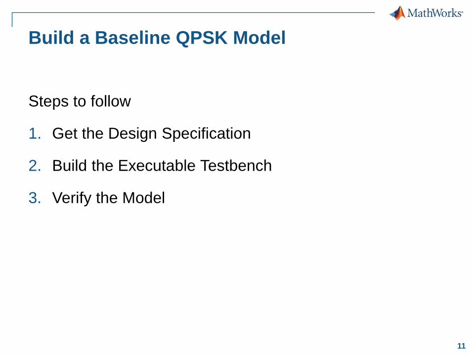
Build a Baseline QPSK Model
Steps to follow
1. Get the Design Specification
2. Build the Executable Testbench
3. Verify the Model
12
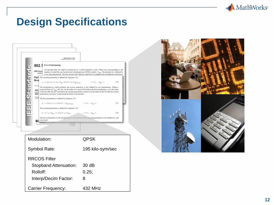
Design Specifications
Modulation: QPSK
Symbol Rate: 195 kilo-sym/sec
RRCOS Filter
Stopband Attenuation: 30 dB
Rolloff: 0.25;
Interp/Decim Factor: 8
Carrier Frequency: 432 MHz
13
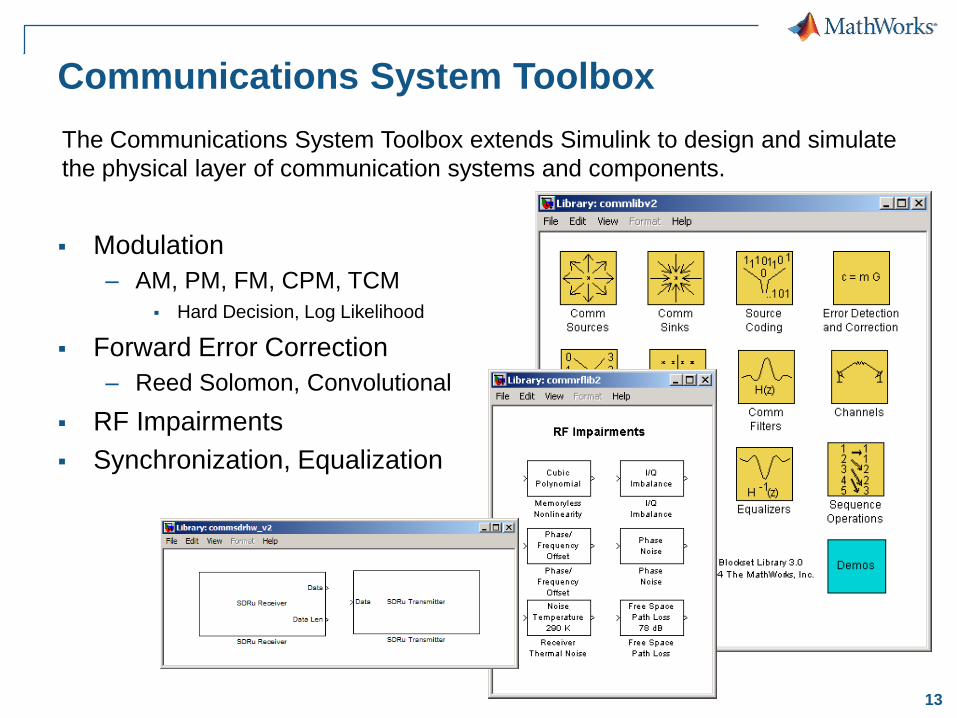
Communications System Toolbox
Modulation
– AM, PM, FM, CPM, TCM
Hard Decision, Log Likelihood
Forward Error Correction
– Reed Solomon, Convolutional
RF Impairments
Synchronization, Equalization
The Communications System Toolbox extends Simulink to design and simulate
the physical layer of communication systems and components.
14
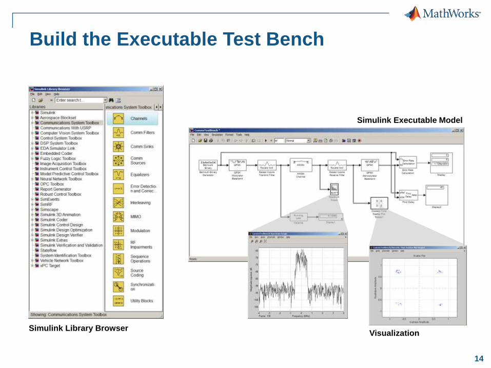
Build the Executable Test Bench
Simulink Library Browser
Simulink Executable Model
Visualization
15
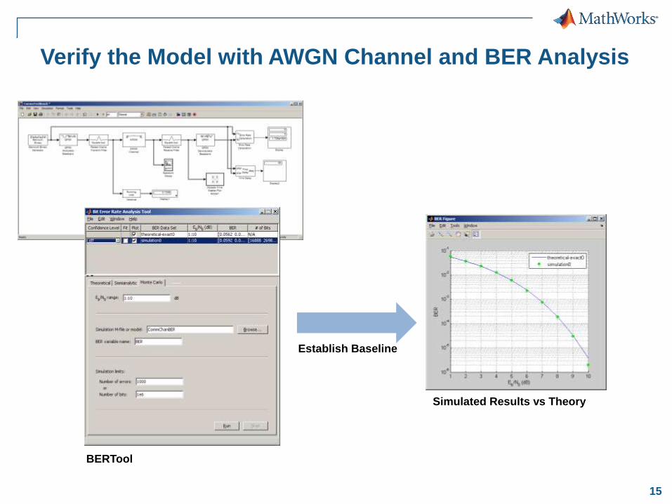
Verify the Model with AWGN Channel and BER Analysis
BERTool
Simulated Results vs Theory
Establish Baseline
16
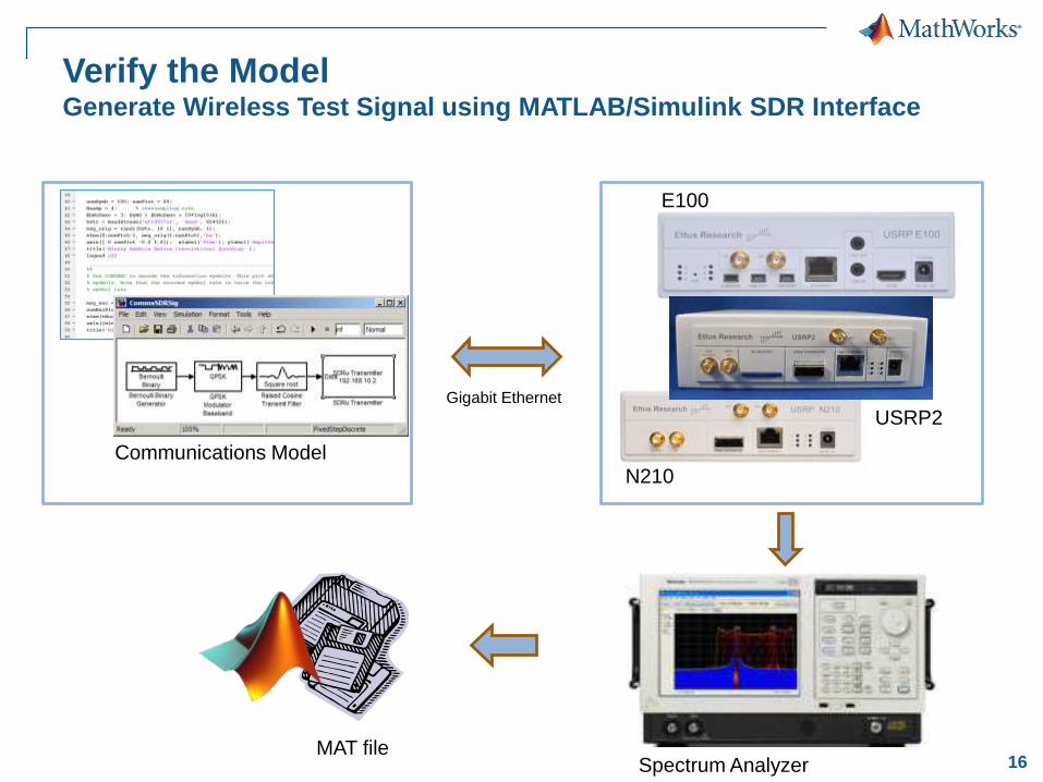
Verify the Model Generate Wireless Test Signal using MATLAB/Simulink SDR Interface
Communications Model
Gigabit Ethernet
USRP2
E100
N210
Spectrum AnalyzerMAT file
17
Implementing a Wireless Receiver on an FPGA
Build a Baseline QPSK Model
o Create Simulink executable model to explore design
choices and determine baseline performance
o Use model to generate wireless test signal
Elaborate and Prototype the Design
o Designing the carrier and timing recovery loops for a
QPSK receiver
o Verify the design with the wireless test signal
Implement on Target Hardware
o Convert the QPSK design to an implementation level
model
o Generate HDL code and integrate with target hardware
18
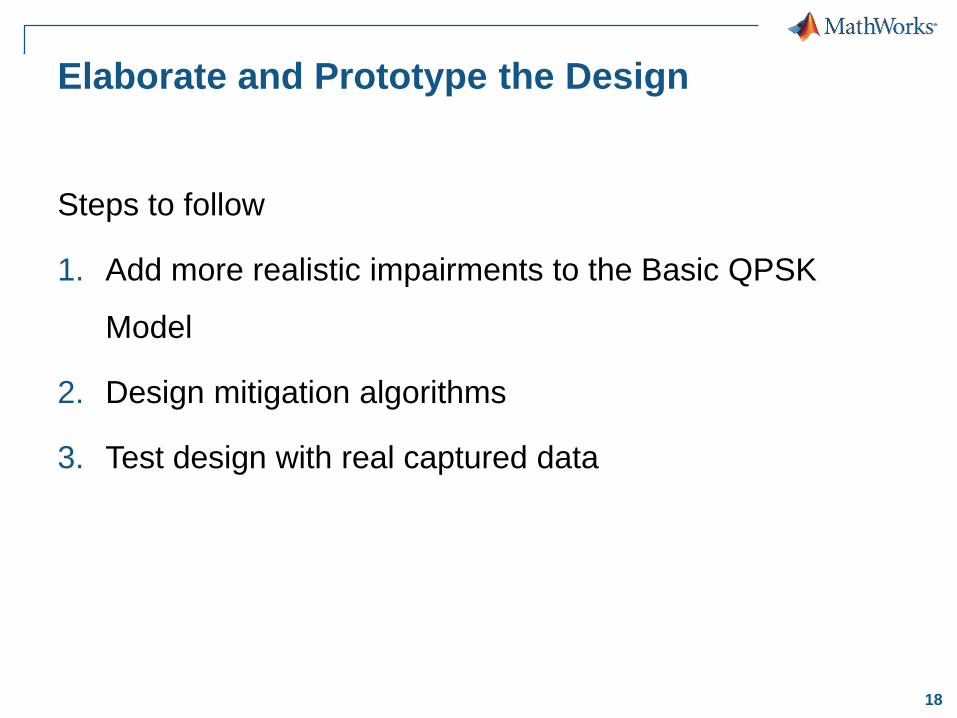
Elaborate and Prototype the Design
Steps to follow
1. Add more realistic impairments to the Basic QPSK
Model
2. Design mitigation algorithms
3. Test design with real captured data
19
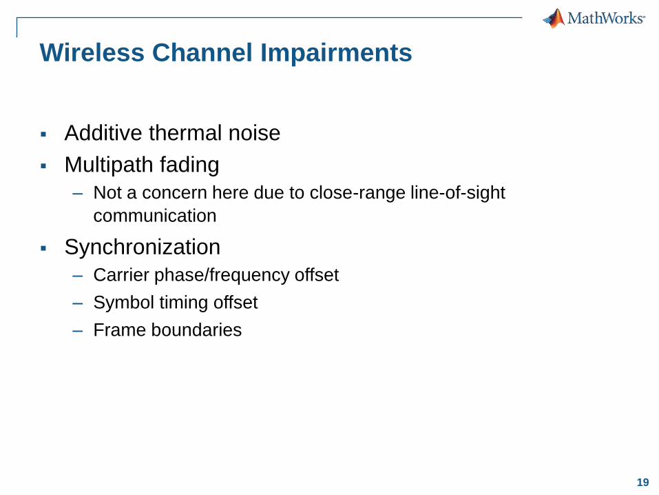
Wireless Channel Impairments
Additive thermal noise
Multipath fading
– Not a concern here due to close-range line-of-sight
communication
Synchronization
– Carrier phase/frequency offset
– Symbol timing offset
– Frame boundaries
20
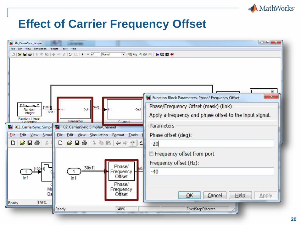
Effect of Carrier Frequency Offset
21
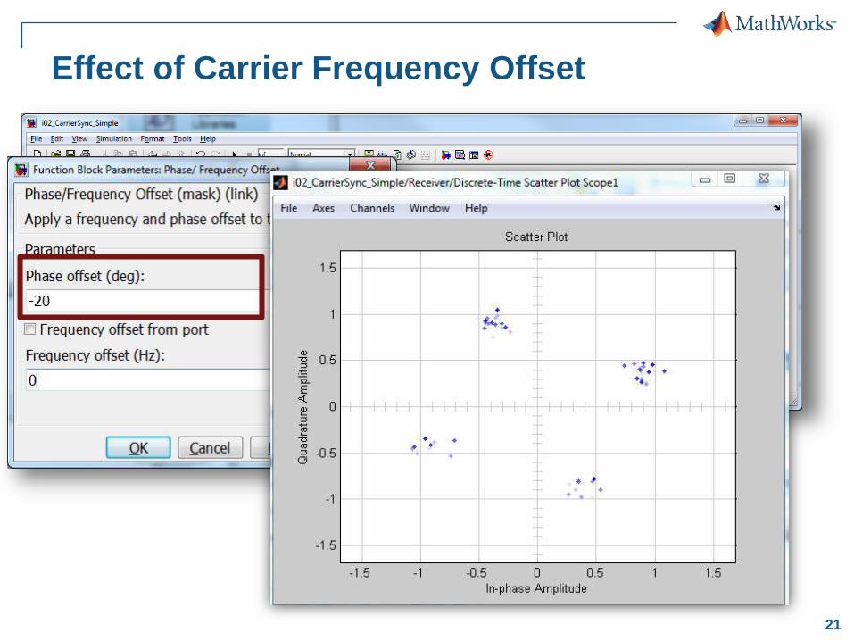
Effect of Carrier Frequency Offset
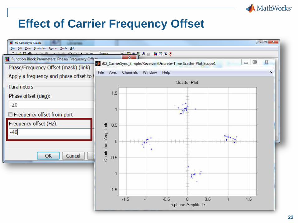
22
Effect of Carrier Frequency Offset
23
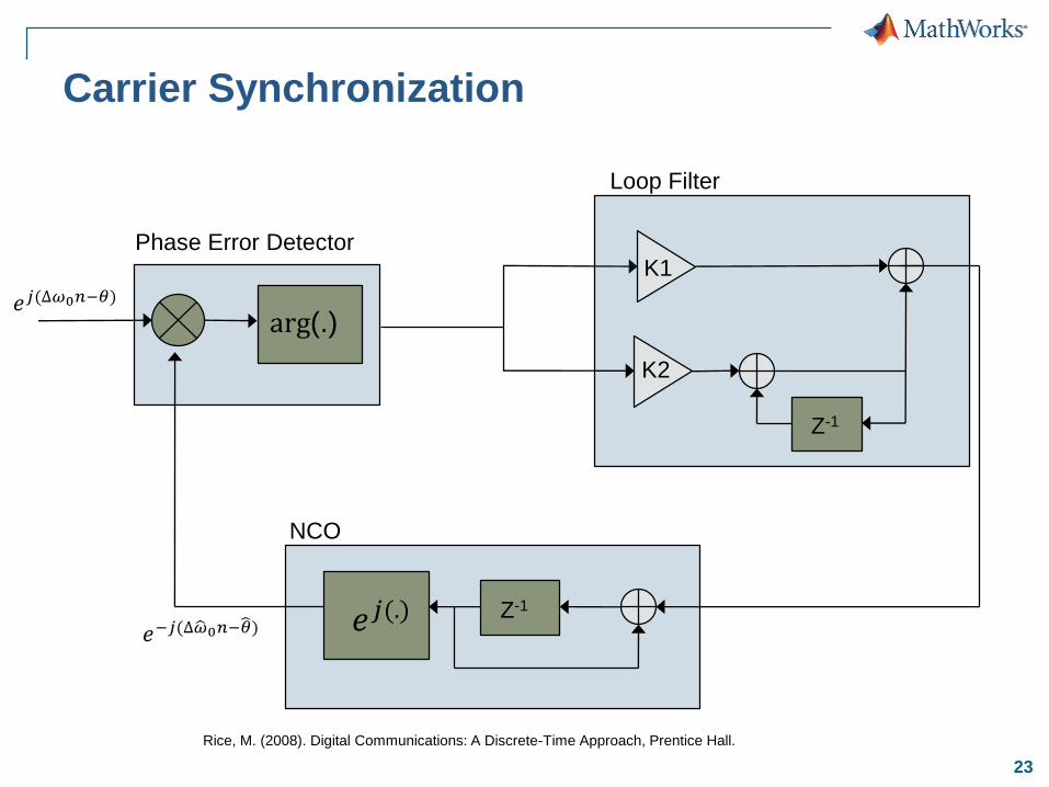
Carrier Synchronization
Z-1
K1
K2
Loop Filter
Rice, M. (2008). Digital Communications: A Discrete-Time Approach, Prentice Hall.
arg(.)
Phase Error Detector
𝑒𝑗(∆𝜔0𝑛−𝜃)
NCO
Z-1
𝑒𝑗(.)𝑒−𝑗(∆ 𝜔0𝑛− 𝜃)
24
Implementing a Wireless Receiver on an FPGA
Build a Baseline QPSK Model
o Create Simulink executable model to explore design
choices and determine baseline performance
o Use model to generate wireless test signal
Elaborate and Prototype the Design
o Designing the carrier and timing recovery loops for a
QPSK receiver
o Verify the design with the wireless test signal
Implement on Target Hardware
o Convert the QPSK design to an implementation level
model
o Generate HDL code and integrate with target hardware
25
Te
st &
Ve
rifica
tion
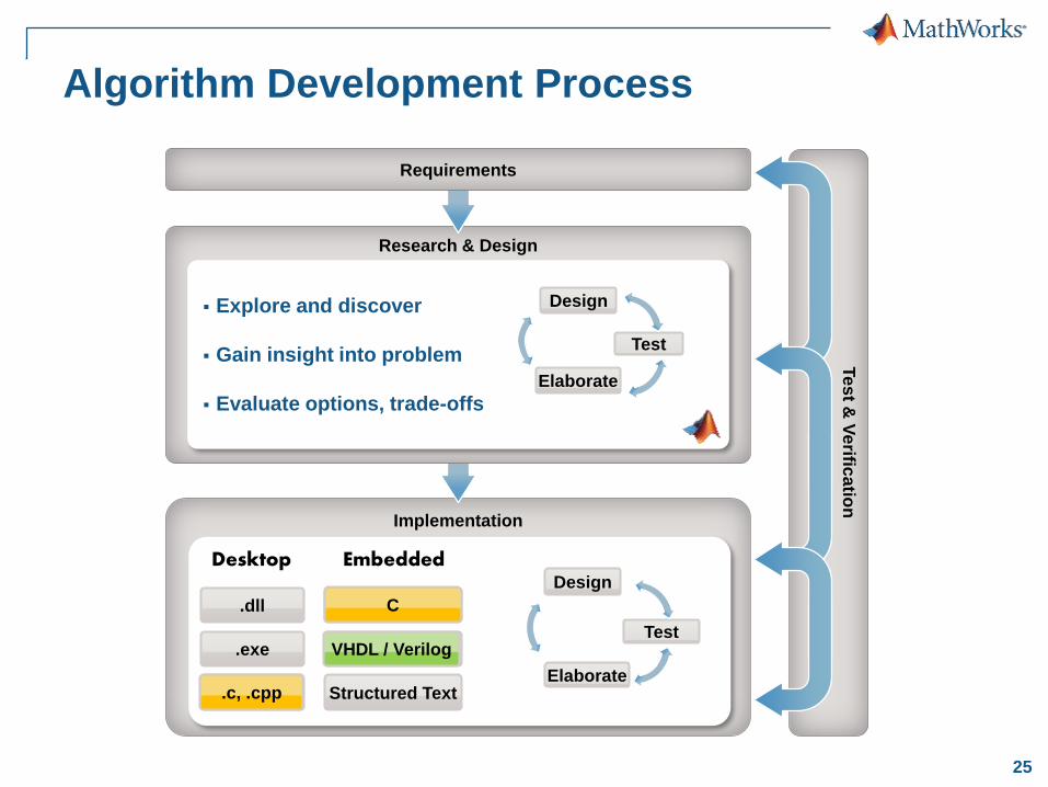
Implementation
Research & Design
Explore and discover
Gain insight into problem
Evaluate options, trade-offs
Test
Design
Elaborate
Algorithm Development Process
Requirements
Test
Design
ElaborateC, C++
.exe
.dll
Desktop
Structured Text
VHDL / Verilog
C, C++
Embedded
.c, .cpp
C
VHDL / Verilog
26
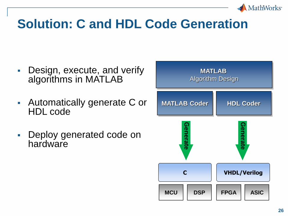
Solution: C and HDL Code Generation
Design, execute, and verify algorithms in MATLAB
Automatically generate C or HDL code
Deploy generated code on hardware
MATLAB
Algorithm Design
FPGA ASIC
HDL Coder
FPGA ASIC
VHDL/Verilog
Gen
era
te
FPGA ASIC
MATLAB Coder
MCU DSP
C
Gen
era
te
27
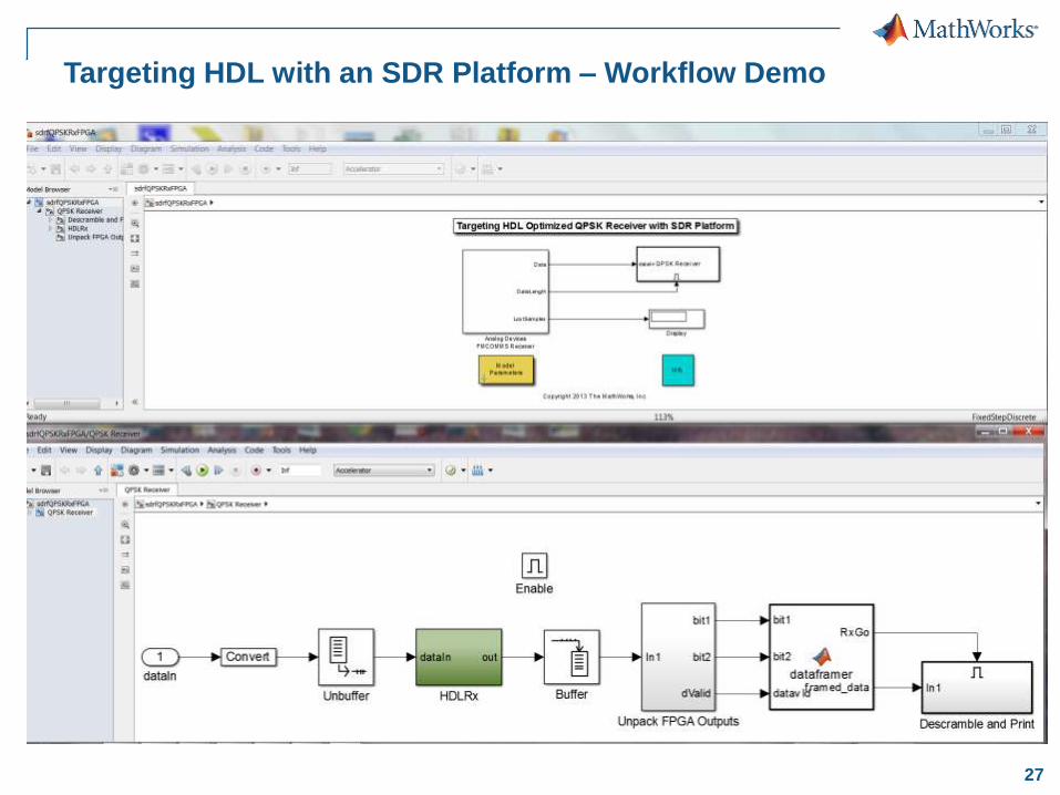
Targeting HDL with an SDR Platform – Workflow Demo
28
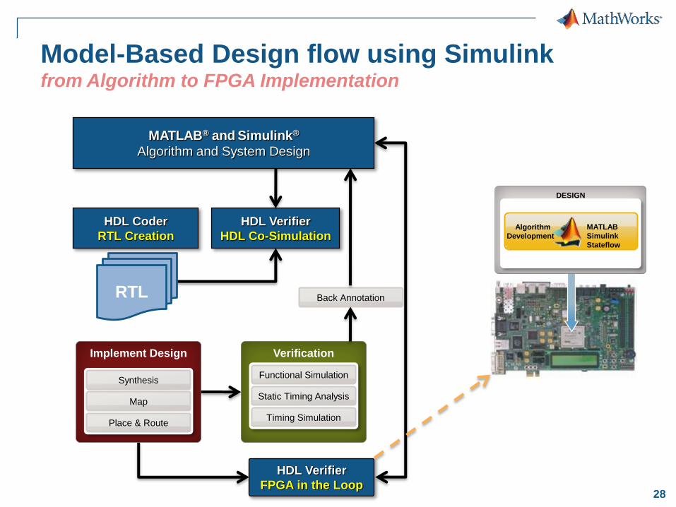
Model-Based Design flow using Simulink from Algorithm to FPGA Implementation
HDL Verifier
FPGA in the Loop
MATLAB® and Simulink®
Algorithm and System Design
Implement Design
Map
Place & Route
Synthesis
Back Annotation
Verification
Static Timing Analysis
Timing Simulation
Functional Simulation
HDL Verifier
HDL Co-Simulation
HDL Coder
RTL Creation
RTL
DESIGN
Algorithm
Development
MATLAB
Simulink
Stateflow

29
Thank You!