Embed Size (px)
Citation preview

ìœéú …ðœíò ìùñ~¶ýò ‹±Ý ô …èß}±ôðýà …ü±…ó-||¶†ë ¬ôï-|ºí†°û …ôë-|‹ù†° ô {†‹·}†ó 4831
Journal of Iranian Association of E
lectrical and Electronics E
ngineers - Vol.2 - N
o.1 - Spring and Summ
er 2005
Abstract: This paper develops a circuit model and con-trollers of fuel cell based distributed generation systems(DGS) in a standalone AC power supply. Dynamicmodel of the fuel cell is considered. To boost low out-put DC voltage of the fuel cell to high DC voltage andcompensate for its slow response during the transient,two full-bridge DC to DC converters are adopted andtheir controllers are designed: a unidirectional full-bridge DC to DC boost converter for the fuel cell and abidirectional full-bridge DC to DC buck/boost convert-er for the battery. For a three-phase DC to AC inverter,a discrete-time state space model in the stationary dqreference frame is derived and two discrete-time slidingmode controllers are designed: voltage controller in theouter loop and current controller in the inner loop. Todemonstrate the proposed circuit model and controlstrategies, a simulation test-bed using Matlab/Simulinkis developed and various results are given.
Keywords: Distributed generation systems, standalone,fuel cells, dynamic modeling, isolated full-bridge DC toDC power converter, three-phase PWM inverter, slid-ing-mode control.
1. INTRODUCTIONEnvironmental-friendly distributed generation systems(DGS) such as fuel cells, wind turbines, hydro turbinesor photovoltaic arrays are rapidly increasing around theworld because they can meet both the increasing demandof electric power and environmental regulations due togreen house gas emission [1]-[8]. Outstanding advancesin Power Electronics and energy storage devices fortransient backup have accelerated penetration of theDGS into electric power generation plants.These DGS technologies can be used for various appli-
cations to a standalone, a grid-interconnection, a cogen-eration, a standby, peak shavings, etc. and have manybenefits such as environmental-friendly, modular elec-tric generation, increased reliability, high power quality,uninterruptible power service, cost savings, on-site gen-eration, and expandability, etc. The fuel cells are electrochemical devices which con-vert chemical energy directly into electric energy byreaction of hydrogen from the fuel and oxygen from theair without regard to climate conditions unlike hydro orwind turbines and photovoltaic arrays [7]-[18], [25]-[26]. Thus, the fuel cells are one of the most attractiveDGS resources for power delivery. However, batteriesneed to be placed in parallel or series with the fuel cellas a temporary energy storage element to support start-up or sudden load changes because the fuel cells can notimmediately respond to such abrupt load changes. For practical analysis of the fuel cell systems, a physi-cal/chemical model [7]-[12] or a first/second ordermodel [13], [14] is used to realize the slow dynamics ofthe fuel cells. However, most of the papers have notaddressed in detail power converter design and control.For single-phase residential applications, the fuel cell ismodeled by a DC voltage source to design low-cost andsmall-sized power converters [15]-[18]. A unidirection-al isolated full-bridge DC to DC power converter can beused to boost low fuel cell voltage [19]-[24]. In addi-tion, a bidirectional full-bridge DC to DC power con-verter can be used for stepping up low battery voltage orstepping down high-voltage-side DC link according tobattery discharge or recharge mode [25], [26].Sedghisigarchi and Feliachi [7], [8] have addressed thefuel-cell dynamic model, and control and stability of thegrid-connected DGS, but their two-part paper deals withonly PI controllers and does not have energy storage
10
Modeling and Control of Fuel Cell Based Distributed GenerationSystems in a Standalone AC Power Supply
Jin-Woo Jung,1 Ali Keyhani,2
1. Samsung SDI Co. Korea2. Dept. of Electrical and computer Eng. Ohio State University, Columbus, USA

ìœéú …ðœíò ìùñ~¶ýò ‹±Ý ô …èß}±ôðýà …ü±…ó-||¶†ë ¬ôï-|ºí†°û …ôë-|‹ù†° ô {†‹·}†ó 4831
Jour
nal o
f Ir
ania
n A
ssoc
iatio
n of
Ele
ctri
cal a
nd E
lect
roni
cs E
ngin
eers
- V
ol.2
- N
o.1
- Sp
ring
and
Sum
mer
200
5
devices for transient backup. Also, a three-phase PWMinverter is not considered in these papers.Also, techniques to produce a sinusoidal AC outputvoltage with low total harmonic distortion (THD) in athree-phase PWM inverter have been reported [27]-[30]. Particularly, even if real-time deadbeat controllers[27]-[29] have low THD for linear load and a fast tran-sient response for load disturbances, it is known thatthey are sensitive to parametric variations and modeluncertainties as well as these techniques have a highTHD under nonlinear load. On the other hand, discrete-time optimal voltage/current controllers in a rotatingreference frame have been proposed for UPS applica-tions of a three-phase PWM inverter [30]. However, itdoes not consider a nonlinear load.The papers stated previously are oriented toward onlyone part of either dynamic modeling of the fuel cell ordesign of power converters with a constant DC voltagesource such as a forward/push-pull DC to DC boostconverter, a single unidirectional full-bridge DC to DCpower converter or a single bidirectional full-bridge DCto DC power converter as well as a three-phase DC toAC inverter.In this paper, simulation studies which cover all the slowdynamics of the fuel cell, a voltage-current polarizationcurve of the stack, a unidirectional full-bridge boost con-verter for the fuel cell, a bidirectional full-bridgebuck/boost DC to DC power converter for the battery,and a three-phase DC to AC inverter are performed forthe fuel-cell-powered DGS to put the battery in parallelto the fuel cell in a standalone AC power supply.Especially, to boost low output DC voltage of the fuelcell to high DC voltage and compensate for its slowresponse during the transient, two full-bridge DC to DCconverters are adopted and an adaptive proportionalcontroller is designed. For a three-phase DC to ACinverter, two discrete-time sliding mode controllers aredesigned to guarantee the good performance such asnearly zero steady state inverter output voltage error,low THD, good voltage regulation, robustness, fasttransient response, and protection of the inverter againstoverload under linear/nonlinear loads. To demonstratethe proposed circuit model and control strategies, asimulation test-bed using Matlab/Simulink is developedfor the standalone AC power generation with a three-phase AC 120 V/60 Hz/50 kVA.The paper is organized as follows. Section II illustratesfuel cell based distributed generation systems in a stand-alone AC power plant. Dynamic model of the fuel cellis shown in Section III. Section IV explains unidirec-tional/bidirectional full-bridge DC to DC power con-verters for the fuel cell and battery. Circuit model of DC
to AC inverter is given in Section V. Section VI presentscontrol system design. Simulation results of full-bridgeDC to DC power converters with dynamics of the fuelcell and three-phase DC to AC inverter are shown inSection VII.
2. FUEL CELL BASED DISTRIBUTED GENERA-TION SYSTEMS IN A STANDALONE AC POWERSUPPLYThe fuel cell can not immediately respond to powerdemand during start-up or sudden load changes due toits slow dynamics. As a result, energy storage elementssuch as batteries or flywheels deliver the remainingpower to the load for the transient. Fuel cell stack voltage, battery position and topology ofDC to DC boost converters can be selected variouslyaccording to the designers [15]-[18]. In this paper, a lowvoltage DC output of the fuel cell is used along with theunidirectional boost converter to avoid reliability dete-rioration by stacking a number of series cells. A lowvoltage battery for backup is connected in parallel to thehigh-voltage-side DC bus through a bidirectionalbuck/boost converter because difficulties in batterymanagement can be significantly reduced. In addition,an isolated full-bridge DC to DC power converter ischosen to boost low output DC voltage of the fuel cellbecause its topology is suitable for high power applica-tions.Based on the DGS unit with the battery in parallel to thefuel cell, two applications are promising in industry asillustrated in Fig. 1: a standalone AC power supply anda grid-interconnection.
Fig. 1: Configuration for two applications.
In this paper, a standalone operation of two applicationsabove is investigated. Fig. 2 depicts a configuration ofthe DGS with parallelly connected fuel cell and batteryfor the standalone AC power plant. It consists of a fuelcell, a battery, unidirectional and bidirectional isolatedfull-bridge DC to DC power converters, a three-phaseDC to AC inverter, an L-C output filter, and a three-phase local load.
11

ìœéú …ðœíò ìùñ~¶ýò ‹±Ý ô …èß}±ôðýà …ü±…ó-||¶†ë ¬ôï-|ºí†°û …ôë-|‹ù†° ô {†‹·}†ó 4831
Journal of Iranian Association of E
lectrical and Electronics E
ngineers - Vol.2 - N
o.1 - Spring and Summ
er 2005
Fig. 2: Configuration of fuel cell based DGS in a stand-alone AC power supply.
Fig. 3 shows a real system diagram of the DGS that con-sists of a reformer, stack, a fuel processor controller, aunidirectional boost converter, a bidirectionalbuck/boost converter, a 3-phase DC to AC inverter, asupervisory controller, two DSP controllers, and a 3-phase load in the standalone AC power generation.
Fig. 3: Detailed system diagram of the DGS with fuelcell and battery.
As described in Fig. 3, the fuel processor controller con-trols the reformer to produce hydrogen for the powerrequested from the supervisory controller, and monitorsthe stack current and voltage. The supervisory con-troller communicates with the fuel cell processor con-troller to equalize the power available from the stack tothe power requested by the load, and to coordinate pro-tections of the fuel cell. Also, it controls the DSP con-troller 1 and 2 for the DC and AC power regulation withsensed output voltages/currents. The DSP controller 1supervises the gating signals of unidirectional and bidi-rectional DC to DC power converters, and the DSP con-troller 2 regulates the gating signals of the three-phaseDC to AC inverter.
3. MODELING OF FUEL CELLAmong several types of the fuel cells categorized by theelectrolyte used, four types are promising for distributed
generation systems: Phosphoric Acid fuel cell (PAFC),Solid Oxide fuel cell (SOFC), Molten Carbonate fuelcell (MCFC), Proton-Exchange-Membrane fuel cell(PEMFC). All types of the fuel cells produce electricity by electro-chemical reaction of hydrogen and oxygen, and the oxy-gen can be easily obtained from compressing air. On thecontrary, hydrogen gas required to produce DC power isindirectly gained from the reformer using fuels such asnatural gas, propane, methanol, gasoline or from theelectrolysis of water. A typical configuration of an autonomous fuel cell sys-tem is described in Fig. 4. As shown in this figure, thefuel cell plants consist of three main parts: a reformer,stack, and power conditioning unit (PCU). First, thereformer produces hydrogen gas from fuels and thenprovides it for the stack. Second, the stack has manyunit cells in series to generate a higher voltage neededfor their applications because a single cell that consistsof electrolyte, separators, and plates, produces approxi-mately 0.7 V DC. Last, the PCU including power con-verters convert a low voltage DC from the fuel cell to ahigh voltage DC and/or a sinusoidal AC.
Fig. 4: Configuration of the fuel cell system.
A. Dynamics of ReformerFor dynamic modeling of the fuel cells, the reformerand stack, which determine the dynamic response of thefuel cell system, are further described. Fig. 5 shows adetailed block diagram of the fuel cell system to illus-trate its operation.
Fig. 5: Detailed block diagram of the fuel cell system.
12

ìœéú …ðœíò ìùñ~¶ýò ‹±Ý ô …èß}±ôðýà …ü±…ó-||¶†ë ¬ôï-|ºí†°û …ôë-|‹ù†° ô {†‹·}†ó 4831
Jour
nal o
f Ir
ania
n A
ssoc
iatio
n of
Ele
ctri
cal a
nd E
lect
roni
cs E
ngin
eers
- V
ol.2
- N
o.1
- Sp
ring
and
Sum
mer
200
5
As depicted in Fig. 5, the fuel cell system consists offuel cell stack and auxiliary systems such as a fuel cellprocessor to request the hydrogen gas, a reformer, an aircompressor to provide pressurized oxygen flow throughthe cathode, a valve to control the hydrogen flowthrough the anode, a humidifier to add moisture to thehydrogen and oxygen gases, and a water-cooling systemto remove heat from the stack. Among the auxiliary systems stated above, the reformersignificantly affects the dynamic behavior of the fuelcell system because it takes several minutes to tens ofseconds to convert the fuel into the hydrogen dependingon the demand of the load current as illustrated in Fig.6. Thus, to investigate an overall operation of fuel cellpowered systems, the dynamics of the reformer need tobe considered, and it may be represented by a secondorder transfer function model [13] or a first order timedelay model [14]. In this paper, a first order transferfunction is used for the dynamic model of the reformer.
Fig. 6: Dynamic model of the reformer.
B. Voltage-Current Polarization Curve of Fuel CellStackThe response of the stack that produces electric DCpower from hydrogen and oxygen is much faster thanthat of the reformer. A voltage-current polarizationcurve of a fuel cell stack represented in Fig. 7 also needsto be considered for the practical model of the fuel cell.That is, cell voltage decreases as the stack currentincreases. Fig. 7 shows a static voltage-current characteristic curveof a single fuel cell. As illustrated in the figure, thereexist three regions: region of activation polarization,region of ohmic polarization, and region of concentra-tion polarization. First, in region of activation polariza-tion, the cell voltage drops rapidly with even small cur-rent increase. Second, in region of ohmic polarization,the cell voltage linearly decreases as current increases,and the fuel cell normally operates in this region. Last,in region of concentration polarization, the voltage col-lapses sharply when current exceed the upper limit ofsafe operation, and as a consequence, operation in thisregion should be avoided because the fuel cell may bedamaged due to primarily starvation of the hydrogen.
Fig. 7: V-I polarization curve of a single fuel cell.
1. Theoretical EMF or ideal voltage (1.16 V)2. Region of Activation Polarization (Reaction Rate
Loss)3. Region of Ohmic Polarization
4. Region of Concentration Polarization (GasTransport Loss)
In this paper, the Proton Exchange Membrane (PEM)Fuel Cells of four promising fuel cells are investigated.Based on an electrochemical process in [10], a Simulinkmodel is developed for the V-I polarization curve of thefuel cell stack as illustrated in Fig. 8.
Fig. 8: Simulink model for V-I polarization curve.
In this figure, the polarization curve of the fuel cell isgenerated using regression models with current, fuelcell temperature, vapor saturation pressure, and oxygenand hydrogen partial pressures. In particular, the oxygenand hydrogen pressures can be estimated from cathodepressure, cathode relative humidity and vapor saturationpressure.To obtain the voltage-current polarization curve of thefuel cell stack, the following assumptions are made:
Fuel cell temperature is 80 C at all times.Gas distribution is uniform.Anode relative humidity is equal to cathode relative
humidity and the value is 75%.The ratio of pressures between the interior and exterior
of the channel is large enough for orifice to be choked.
13

ìœéú …ðœíò ìùñ~¶ýò ‹±Ý ô …èß}±ôðýà …ü±…ó-||¶†ë ¬ôï-|ºí†°û …ôë-|‹ù†° ô {†‹·}†ó 4831
Journal of Iranian Association of E
lectrical and Electronics E
ngineers - Vol.2 - N
o.1 - Spring and Summ
er 2005
The Nernst's equation is applied.The cell utilization is 85%.
Based on the above assumptions, the polarization curvesof the stack of 250 cells in series for various cathodepressures [1, 1.2, 1.4, 1.6, 1.8, 2 bar] are shown in Fig.9. As represented in this figure, the linearized polariza-tion curve corresponding to cathode pressure (pca) of 1.2bar is selected for a 50 kW PEM fuel cell and it will beused for Simulink model of the fuel cell stack.
Fig. 9: V-I polarization curves at different cathode pres-sures (pca).
Note that the fuel cell has the slow dynamic responseduring transient. At initial startup, it takes 90 secondsfor the fuel cell to reach steady state. Whenever there isa change in power demand, the fuel cell takes 60 sec-onds to reach a new steady state because the hydrogenflow rates can be slowly adjusted to meet the powerdemand [15]-[18]. To compensate for such a sluggishresponse of the fuel cell, an energy storage device suchas a battery may be required to achieve the end-useneeds. For a 50 kW PEM fuel cell, this implies that dur-ing startup (90 sec), the energy storage requirement is4500 kJ or 1.25 kWh. Furthermore, dynamic loadchanges should be supported by the batteries for 60 sec-onds. For lead-acid batteries, about 20 % change ofnominal charge state may be reasonable to avoid deepdischarge and guarantee long service life as well asreserve capacity in the case of an extended fault with thefuel cell. Fig. 10 shows a discharge curve of fuel celland battery to determine the battery capacity.Considering only 20 % discharge of the nominal batterycharge state for 90 seconds (startup), the minimum stor-age requirement of the batteries to support the fuel cellduring all transients is about 22,500 kJ or 6.25 kWh.
Fig. 10: Discharge curve of fuel cell and battery.
5. UNIDIRECTIONAL/BIDIRECTIONAL FULL-BRIDGE DC TO DC POWER CONVERTERSTo boost low output DC voltage of the fuel cell to highDC voltage, a forward DC to DC boost converter, apush-pull DC to DC boost converter or an isolated full-bridge DC to DC power converter can be selected.Among these power converters, two phase-shifted full-bridge DC to DC converters, which are one of the mostattractive topologies for high power generation [19]-[26], are adopted as described in Fig. 11: a unidirec-tional full-bridge DC to DC boost converter for the fuelcell and a bidirectional full-bridge DC to DC boost/buckconverter for battery.
Fig. 11: Unidirectional/bidirectional DC to DC powerconverters.
In Fig. 11, the unidirectional power converter systemfor the fuel cell consists of a fuel cell, an input filter (L1,C1), a full-bridge power converter "1" (F1 to F4), a highfrequency transformer (N1:N2), a bridge-diode (DF1 toDF4), and an output filter (L2, C2), while the bidirec-tional power converter system for the battery consists ofa battery, a static switch (SB), two full-bridge powerconverter "2" (B1 to B4) and "3" (B11 to B44), and a high
14

ìœéú …ðœíò ìùñ~¶ýò ‹±Ý ô …èß}±ôðýà …ü±…ó-||¶†ë ¬ôï-|ºí†°û …ôë-|‹ù†° ô {†‹·}†ó 4831
Jour
nal o
f Ir
ania
n A
ssoc
iatio
n of
Ele
ctri
cal a
nd E
lect
roni
cs E
ngin
eers
- V
ol.2
- N
o.1
- Sp
ring
and
Sum
mer
200
5
15
frequency transformer (n1:n2). Fig. 12 shows power flows of DC to DC power con-verters for battery discharge and battery recharge. Asshown in Fig. 12, the unidirectional full-bridge DC toDC boost converter permits only one directional powerflow from the fuel cell to the load because a reverse cur-rent can damage the fuel cell, and a response speed ofthe power converter should be slow enough to meetslow dynamic response of the fuel cell. On the otherhand, the bidirectional full-bridge DC to DC power con-verter allows both directional power flows for batterydischarge and recharge, and its response also should befast to compensate for the slow dynamics of the fuel cellduring start-up or sudden load changes. For battery discharge mode illustrated in Fig. 12 (a),which occurs when a startup or a sudden load increase,the fuel cell starts delivering electric power to the loadand the battery instantly provides power until the fuelcell reaches a full operation state. After transient opera-tion, only the fuel cell feeds electric power to the load.For battery recharge mode shown in Fig. 12 (b), the bat-tery absorbs the energy overflowed from the fuel cell toprevent DC-link voltage VDC from being overchargedduring a sudden load decrease, and then the battery isrecharged by the fuel cell in a steady-state until it reach-es a nominal voltage.
Fig. 12: Power flows of DC to DC power converters.(a) Battery discharge. (b) Battery recharge.
6. THREE-PHASE DC TO AC INVERTERA circuit model of a three-phase DC to AC inverter withL/C output filter is further described in Fig. 13. Asshown in the figure, the system consists of a DC voltagesource (Vdc), a three-phase PWM inverter (S1 to S6), anoutput filter (Lf and Cf), and a three-phase load (RL).Note that the first stage of DGS that consists of a fuelcell, a battery, and two full-bridge DC to DC power con-verters is replaced with the DC voltage source (Vdc)because during transient the battery fully supports thefuel cell with a slow dynamic response to keep the DC-link voltage (Vdc) constant and as a result, the first stagecan be considered as a stiff DC energy source.
Fig. 13: Three-phase DC to AC inverter with L-C out-put filter.
The circuit model described in Fig. 13 uses the follow-ing quantities. The inverter output line-to-line voltagesand output currents are represented by the vectors Vi =[ViAB ViBC ViCA]T and Ii = [iiA iiB iiC]T. Also, the load lineto neutral voltage and phase current vectors can be rep-resented by VL = [VLAn VLBn VLCn]T and IL = [iLA iLB iLC]T
, respectively. The L-C output filter yields the following state equa-tions by KCL and KVL:
(1)
where,
To implement the space vector PWM, the above stateequations can be transformed from the abc referenceframe into stationary dq reference frame that consists ofthe horizontal (d) and vertical (q) axes. The relationbetween these two reference frames is below
, (2)
(a)
(b)
if
Lif
ii
Lf
if
L
LLdt
d
CCdt
d
VVTI
T
IIV
11
11
+−=
−=
−−
−=
101
110
011
iT
abcsdq fKf =0
where, , fdq0=[fd fq f0]T,
fabc=[fa fb fc]T, and f denotes either a voltage or a currentvariable.
Using (2), the (1) can be transformed below
, (3)
where, .
The given plant model (3) can be expressed as the fol-lowing continuous-time state space equation, (4)
where, , ,
, , , .
Note that the load line to neutral voltage VLdq andinverter output phase current Iidq are the state variables,the inverter output line-to-line voltage Vidq is the controlinput (u), and the load phase current ILdq is defined asthe disturbance (d).
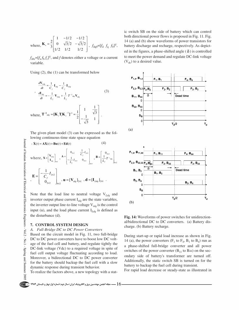
7. CONTROL SYSTEM DESIGNA. Full-Bridge DC to DC Power ConvertersBased on the circuit model in Fig. 11, two full-bridgeDC to DC power converters have to boost low DC volt-age of the fuel cell and battery, and regulate tightly theDC-link voltage (Vdc) to a required voltage in spite offuel cell output voltage fluctuating according to load.Moreover, a bidirectional DC to DC power converterfor the battery should backup the fuel cell with a slowdynamic response during transient behavior.To realize the factors above, a new topology with a stat-
ic switch SB on the side of battery which can controlboth directional power flows is proposed in Fig. 11. Fig.14 (a) and (b) show waveforms of power transistors forbattery discharge and recharge, respectively. As depict-
ed in the figures, a phase-shifted angle ( ) is controlledto meet the power demand and regulate DC-link voltage(Vdc) to a desired value.
Fig. 14: Waveforms of power switches for unidirection-al/bidirectional DC to DC converters. (a) Battery dis-charge. (b) Battery recharge.
During start-up or rapid load increase as shown in Fig.14 (a), the power converters (F1 to F4, B1 to B4) run asa phase-shifted full-bridge converter and all powerswitches of the power converter (B11 to B44) on the sec-ondary side of battery's transformer are turned off.Additionally, the static switch SB is turned on for thebattery to backup the fuel cell during transient.For rapid load decrease or steady-state as illustrated in
12][ ×= LdqId12][ ×= idqVu2422
22
0
1
××
×
−=
IC f
E
24
22
11
0
×
×
= −
idq
f
TL
B
44
2222
2222
01
10
×
××
××
−=
IL
IC
f
fA
14×
=
idq
Ldq
I
VX
)()()()( tttt EdBuAXX ++=&
−== −−−
13
13
11
2
111]KT[KT 1sisidq
−−−
=2/12/12/1
23230
2/12/11
3
2sK
ìœéú …ðœíò ìùñ~¶ýò ‹±Ý ô …èß}±ôðýà …ü±…ó-||¶†ë ¬ôï-|ºí†°û …ôë-|‹ù†° ô {†‹·}†ó 4831
Journal of Iranian Association of E
lectrical and Electronics E
ngineers - Vol.2 - N
o.1 - Spring and Summ
er 2005
16
idqidq
f
Ldq
f
idq
Ldq
f
idq
f
Ldq
TLLdt
d
CCdt
d
VVI
IIV
111
11
−+−=
−=
(a)
(b)

ìœéú …ðœíò ìùñ~¶ýò ‹±Ý ô …èß}±ôðýà …ü±…ó-||¶†ë ¬ôï-|ºí†°û …ôë-|‹ù†° ô {†‹·}†ó 4831
Jour
nal o
f Ir
ania
n A
ssoc
iatio
n of
Ele
ctri
cal a
nd E
lect
roni
cs E
ngin
eers
- V
ol.2
- N
o.1
- Sp
ring
and
Sum
mer
200
5
17
Fig. 14 (b), the power converters (F1 to F4, B11 to B44)operate as a phase-shifted full-bridge converter, where-as the power converter (B1 to B4) on the primary side ofbattery's transformer acts as a regular PWM full-bridgeconverter. Also, the static switch SB is turned off forabsorption of overcharged power or battery recharge insteady-state time.Fig. 15 shows a control block diagram of unidirectionaland bidirectional full-bridge DC to DC converters. InFig. 15, load current IL, fuel cell current IF2 on the highvoltage side, battery voltage VB and DC-link voltageVdc are measured to perform closed-loop control. Notethat high frequency components of all measured cur-rents are filtered out by low-pass filter for accurate volt-age and current control.
Fig. 15: Control block diagram of DC to DC power con-verters.
As represented by Fig. 15, control variables of two DC
to DC power converters are phase-shifted angels ( f ,
b), where f is a phase-shifted angle for the fuel cell
and b is a phase-shifted angle for the battery, and there
exist three main loops: start-up, |ei| > , and |ei| < ,where ei = IL IF2 and is a small positive value.
During start-up, phase-shifted angles ( f , b) of twopower converters are given by "Profile A" predeter-
mined for soft starting. For |ei| > , a difference betweena filtered load current (IL) and a filtered fuel cell current(IF2) is used to determine either "load increase" or "loaddecrease". The angles are determined by "Profile B" and"Profile C" which meet dynamic characteristics of thefuel cell and battery, depending on load increase or load
decrease. If the difference is positive, "Profile B" isselected for the battery to backup the fuel cell. On theother hand, if the difference is negative, "Profile C" ischosen so that the battery can absorb electric energyoverflow from the fuel cell due to abrupt load decrease.
After |ei| goes within , an adaptive proportional con-troller is used to regulate the DC-link voltage Vdc and adiscrete-time PI controller is used to recharge the bat-tery from the fuel cell until the battery voltage VB reach-es a nominal value. The adaptive controller is designedto prevent abrupt switching action which can cause alarge amount of current ripple by properly adjusting thegain according to the error between reference DC-link
voltage V*dc and measured voltage Vdc. Also, if fuel cell
stack current IF and battery current IB are above thelimit which can damage cells, two power converterswill shut down.
B. Three-Phase DC to AC InverterTo supply a qualified AC power to the local load con-nected to the distributed generation systems (DGS),good performance such as a low THD, a fast transientresponse, and over-current protection should be guaran-teed under linear/nonlinear loads. Fig. 16 shows a control block diagram of a three-phaseDC to AC inverter. As represented by Fig. 16, two dis-crete-time sliding mode controllers (DSMC) are pro-posed to perform zero steady state tracking error, THDreduction, and fast and no-overshoot response: currentcontroller in the inner loop and voltage controller in theouter loop. First of all, the DSMC is suitable for digitalimplementation since it does not exhibit the chatteringphenomena due to direct digital implementation of con-tinuous time sliding mode control [31].
Fig. 16: Control block diagram of a three-phase DC toAC inverter.
1) Current Controller in the Inner LoopFor design of a discrete-time current controller, the con-tinuous-time state space equation (4) of the plant can betransformed to a discrete form:
, (5)
−==
++=+
)()()(
)()(
)()()()1(
_11
11
***
kkk
kk
kkkk
refidq yye
XCy
dEuBXAX

where, , , ,
, , , .
In order to control the output y1(k) to follow the refer-ence y1_ref(k), a sliding mode manifold can be selectedbelow
. (6)
Therefore, discrete-time sliding mode can be reached ifthe control input u(k) is designed as the solution of:
. (7)
The control law that satisfies (7) and yields motion inthe manifold s(k) = 0 is called 'equivalent control' and isgiven:
. (8)
If the control is limited by , then the followingmodified control input can be applied:
. (9)
With control law (9), the discrete-time sliding mode canbe reached after a finite number of steps and the controlvoltage limit u0 is also determined by the SVPWMinverter.
2) Voltage Controller in the Outer LoopFor the dynamics of the DSMC to be included in theouter loop, its model has to be combined with the orig-inal plant.After the dynamics (8) of the DSMC is included in (5),the overall plant can be expressed:
, (10)
where , , ,
, , , .
To be similar to the current controller, a sliding modemanifold may be chosen in the form of:
. (11)
Thus, if the control input u1(k) is designed to be thesolution of s(k+1)=0, the discrete-time sliding mode can
be reached after a finite number of steps and the equiv-alent control (u1eq) is given by:
. (12)
If the control is limited by , then the following modi-fied control input can be applied:
. (13)
Note that the control law u1eq(k) is limited by 300% ofthe rated current.
8. SIMULATION RESULTSTo validate the effectiveness of the fuel cell model andcontrol strategies of full-bridge DC to DC and three-phase DC to AC power converters that are proposed forthe fuel cell based distributed generation systems in thestandalone AC power plant, a simulation test bed usingMatlab/Simulink is constructed for an AC 120 V (L-n)/60 Hz/50 kVA. In this paper, to overcome an excessive computationtime due to three power converters and high PWM fre-quencies, it is assumed that the dynamic response timeof the fuel cell is significantly reduced compared to itsnormal response time. Also, the simulation test bed isdivided into two parts: two full-bridge DC to DC powerconverters with the dynamic model of the fuel cell anda three-phase DC to AC inverter. It is reasonable if theDC to DC power converters tightly regulate the DC-linkbus voltage (Vdc) that is used as an input of the three-phase DC to AC inverter within a desired value.
A. Full-Bridge DC to DC Power ConvertersTo demonstrate the fuel cell model and control schemepresented for two full-bridge DC to DC power convert-ers, a simulation test bed using Matlab/Simulink isdeveloped. Fig. 17 shows a Simulink model of the fuel cell, and itconsists of a power request, a power to current conver-sion, a first-order transfer function for the transientresponse of the reformer, a controlled current source, alinearized polarization curve for the modeling of thestack, and a controlled voltage source.
Fig. 17: Simulink model of the fuel cell.
>
≤=
ieqeqeq
ieqeq
ukkk
u
ukk
k)(for )(
)(
)(for )(
)(11
1
0
11
1 uuu
uu
u
( ) ( ))()()()( *1*1 kkkk ddddLdqddeq dECXACVBCu −−= −
)()()( kkk refd yXCs −=
)()( ,1 kk idqcmdIu = ( ) *1
1*1
** ECBCBEE−
−=d ( )1*
1* −
= BCBBd
( ) *1
1*1
** ACBCBAA−
−=d [ ]2222 0 ××= IdC ][ LdqVy =
−==
++=+
)()()(
)()()()()()1( 1
kkk
kkkkkk
refvdq
d
ddd
yye
XCydEuBXAX
>
≤=
veqeq
eq
v
veqeq
ukkk
u
ukk
k)(for )(
)(
)(for )(
)(uu
u
uuu
vuk ≤)(u
( ) ( ))(ˆ)()()( *1
*1
*1*1 kkkk idqeq dECXACIBCu −−= −
)1()1()1( _11 +−+=+ kkk refyys
)()()()()( _11_11 kkkkk refref yXCyys −=−=
∫ −= z zT T de0)(* ττ EE A ∫ −= z zT T de0
)(* ττ BB A zTeAA =*
][ LqdId =
=
1000
01001C ][ *
_1 idqref Iy =][1 idqIy =
ìœéú …ðœíò ìùñ~¶ýò ‹±Ý ô …èß}±ôðýà …ü±…ó-||¶†ë ¬ôï-|ºí†°û …ôë-|‹ù†° ô {†‹·}†ó 4831
Journal of Iranian Association of E
lectrical and Electronics E
ngineers - Vol.2 - N
o.1 - Spring and Summ
er 2005
18

ìœéú …ðœíò ìùñ~¶ýò ‹±Ý ô …èß}±ôðýà …ü±…ó-||¶†ë ¬ôï-|ºí†°û …ôë-|‹ù†° ô {†‹·}†ó 4831
Jour
nal o
f Ir
ania
n A
ssoc
iatio
n of
Ele
ctri
cal a
nd E
lect
roni
cs E
ngin
eers
- V
ol.2
- N
o.1
- Sp
ring
and
Sum
mer
200
5
19
Fig. 18 shows a Simulink model of two full-bridge DCto DC power converters with the fuel cell and the bat-tery, and it consists of a fuel cell, an input filter (L1 andC1), a unidirectional isolated full-bridge DC to DCpower converter, an output filter (L2 and C2), a battery,a static switch (SB), a bidirectional isolated full-bridgeDC to DC power converter, two PWM controllers, anda load. The system parameters are given in Table I.
Fig. 18: Simulink model of full-bridge DC to DC powerconverters with the fuel cell and battery.
TABLE I SYSTEM PARAMETERS
To show a general dynamic response of the fuel cell,assume that it takes 12 msec for fuel cell to reach fromno-load to full load and takes 4 msec (1/3 of the increas-ing time) and vice versa [14]. Fig. 19 to 21 show simu-lation results under startup, a sudden load increase, anda sudden load decrease, respectively. Each figure indicates: (1) Power request (P), (2) Fuelcell voltage (VC1), (3) Fuel cell current (IF), (4) Filteredoutput current (IF2) of fuel cell on DC-link side, (5)Filtered output current (IB2) of battery on DC-link side,and (6) High-side DC-link voltage (Vdc).In Fig. 20, a power request signal is changed from 0 to20 kW at 42 msec, and then 20 kW to 40 kW at 62 msec.In Fig. 21, the power request signal is changed from 0to 40 kW at 42 msec, and dropped to 20 kW at 62 msec.
Fig. 19: Simulation waveforms during start-up.
Fig. 20: Simulation waveforms under a sudden loadincrease.
Fig. 21: Simulation waveforms under a sudden loaddecrease.

As depicted in Fig. 19 to 21, the fuel cell current (IF)has some delay because it takes some time for the fuelto be converted to the hydrogen, which is demanded forthe request power, and the fuel cell voltage and currentdepend on each other as voltage-current polarizationcurve of the stack. Also, the DC-link bus (Vdc) is nearly constant duringthe transients because the battery appropriately backs upthe fuel cell. The battery is discharged during startupand abrupt load increase, while it slowly recharged bythe fuel cell to reach a nominal value during rapid loaddecrease or in steady-state time.
B. Three-Phase DC to AC InverterTo validate the control strategy proposed for three-phase DC to AC inverter, a simulation test bed usingMatlab/Simulink is constructed as illustrated in Fig. 22,and the system parameters are given in Table II.
Fig. 22: Simulink model for a 3-phase PWM inverter.
TABLE II SYSTEM PARAMETERS
Fig. 23 and 24 show the results under a linear load (p.f.= 0.8) and a nonlinear load with a three-phase diodebridge, respectively. In Fig. 25 and 26, the simulationresults show a resistive load step change at 50 msecfrom 0 to 40 kW, and vice versa. Fig. 27 shows simula-tion results under a resistive unbalanced load, i.e., thephase A and B are normal, while the phase C is open at50 msec.
Fig. 23: Results under a linear load (p.f. =0.8).
Fig. 24: Results under a nonlinear load.In Fig. 23 through 27, each figure indicates: (1) Inverteroutput line to line voltage (ViAB), (2) Load phase volt-ages (VLAn, VLBn, VLCn), (3) Inverter output phase cur-rents (iiA, iiB, iiC), (4) Load phase currents (iLA, iLB, iLC),and (5) Load active power (PL) and reactive power (QL).
Fig. 25: Results under a resistive balanced load step
ìœéú …ðœíò ìùñ~¶ýò ‹±Ý ô …èß}±ôðýà …ü±…ó-||¶†ë ¬ôï-|ºí†°û …ôë-|‹ù†° ô {†‹·}†ó 4831
Journal of Iranian Association of E
lectrical and Electronics E
ngineers - Vol.2 - N
o.1 - Spring and Summ
er 2005
20

ìœéú …ðœíò ìùñ~¶ýò ‹±Ý ô …èß}±ôðýà …ü±…ó-||¶†ë ¬ôï-|ºí†°û …ôë-|‹ù†° ô {†‹·}†ó 4831
Jour
nal o
f Ir
ania
n A
ssoc
iatio
n of
Ele
ctri
cal a
nd E
lect
roni
cs E
ngin
eers
- V
ol.2
- N
o.1
- Sp
ring
and
Sum
mer
200
5
change (0 to 40 kW).
Fig. 26: Results under a resistive balanced load stepchange (40 kW to 0).
Fig. 27: Results under a resistive unbalanced load(Phase A & B: normal and Phase C: open at 50 msec.).
From Fig. 23 to 27, the proposed control methoddemonstrates the good performance such as a low THD,a fast transient response, and over-current protectionunder the linear load, nonlinear load, and even resistiveload step changes. Note that it takes 1/60 seconds for thePL and QL to be accurately calculated using Simulinkmodel in the figures.
9. CONCLUSIONSThis paper has described the circuit model and con-troller design of the fuel-cell-powered DGS to put thebattery in parallel to the fuel cell in a standalone ACpower supply. A simulation test-bed using Matlab/Simulink is present-
ed, which includes the dynamic model of the fuel cell,the unidirectional full-bridge DC to DC boost converter(fuel cell), the bidirectional full-bridge DC to DCbuck/boost converter (battery), and the three-phase DCto AC inverter.Especially, a new topology with a static switch on theside of battery which can control both directional powerflows is proposed for the bidirectional full-bridge DC toDC buck/boost converter. For three power converters,the controllers are designed: an adaptive proportionalcontroller for two DC to DC power converters and twodiscrete-time sliding mode controllers for the three-phase DC to AC inverter. From Fig. 19 to 27, the effec-tiveness of the proposed circuit model and control meth-ods is validated.
ACKNOWLEDGMENTThis work was supported in part by the NationalScience Foundation under the grant NSF ECE 0501349.
REFERENCES[1] M. N. Marwali and A. Keyhani, "Control ofDistributed Generation Systems, Part I: Voltages andCurrents Control," IEEE Transaction on PowerElectronics, vol. 19, pp. 1541-1550, Nov. 2004.[2] M. N. Marwali, J. W. Jung, and A. Keyhani,"Control of Distributed Generation Systems, Part II:Load Sharing Control," IEEE Trans. on PowerElectronics, vol. 19, pp. 1551-1561, Nov. 2004.[3] A. A. Chowdhury, S. K. Agarwal, D. O. Koval,"Reliability modeling of distributed generation in con-ventional distribution systems planning and analysis,"IEEE Transactions on Industry Applications, vol. 39,pp. 1493-1498, Sept.-Oct. 2003.[4] T. Monai, I. Takano, H. Nishikawa, and Y. Sawada,"Response characteristics and operating methods ofnew type dispersed power supply system using photo-voltaic fuel cell and SMES," IEEE Power EngineeringSociety Summer Meeting, vol. 2, pp. 874-879, July2002. [5] J. L. Del Monaco, "The Role of DistributedGeneration in the Critical Electric PowerInfrastructure," IEEE-Power Engineering SocietyWinter Meeting, vol. 1, pp. 144 -145, 2001. [6] L. Philipson, "Distributed and DispersedGeneration: Addressing the Spectrum of ConsumerNeeds," IEEE-Power Engineering Society SummerMeeting, vol. 3, pp. 1663 -1665, 2000.[7] K. Sedghisigarchi and A. Feliachi, "Dynamic andTransient Analysis of Power Distribution Systems WithFuel Cells-Part I: Fuel-Cell Dynamic Model," IEEETransactions on Energy Conversion, vol. 19, pp. 423-
21
ìœéú …ðœíò ìùñ~¶ýò ‹±Ý ô …èß}±ôðýà …ü±…ó-||¶†ë ¬ôï-|ºí†°û …ôë-|‹ù†° ô {†‹·}†ó 4831
Journal of Iranian Association of E
lectrical and Electronics E
ngineers - Vol.2 - N
o.1 - Spring and Summ
er 2005
428, June 2004.[8] K. Sedghisigarchi and A. Feliachi, "Dynamic andTransient Analysis of Power Distribution Systems WithFuel Cells-Part II: Control and Stability Enhancement,"IEEE Transactions on Energy Conversion, vol. 19, pp.429-434, June 2004.[9] L.Y. Chiu and B. M. Diong, "An improved small-signal model of the dynamic behavior of PEM fuelcells," IEEE 38th IAS Annual Meeting, vol. 2, pp. 709-715, Oct. 2003.[10] J. T. Pukrushpan, H. Peng, and A. G.Stefanopoulou, "Simulation and analysis of transientfuel cell system performance based on a dynamic reac-tant flow model," Proc. of ASME IMECE'02, 2002.[11] S. Yerramalla, A. Davari, A. Feliachi, "Dynamicmodeling and analysis of polymer electrolyte fuel cell,"IEEE Power Engineering Society Summer Meeting,vol. 1, pp. 82-86, July 2002.[12] J. T. Pukrushpan, A. G. Stefanopoulou, and H.Peng, "Modeling and control for PEM fuel cell stacksystem," American Control Conference, vol. 4, pp.3117-3122, May 2002.[13] K. H. Hauer, "Dynamic interaction between theelectric drive train and fuel cell system for the case ofan indirect methanol fuel cell vehicle,"35th IECECMeeting, vol. 2 , pp. 1317-1325, July 2000.[14] Yoon-Ho Kim and Sang-Sun Kim, "An electricalmodeling and fuzzy logic control of a fuel cell genera-tion system," IEEE Transactions on Energy Conversion,vol. 14, no. 2, pp. 239-244, June 1999.[15] G. K. Andersen, C. Klumpner, S. B. Kjaer, and F.Blaabjerg, "A new green power inverter for fuel cells,"IEEE PESC'02, vol. 2, pp. 727-733, June 2002.[16] R. Gopinath, Sangsun Kim, Jae-Hong Hahn, M.Webster, J. Burghardt, S. Campbell, D. Becker, P.Enjeti, M. Yeary, and J. Howze, "Development of a lowcost fuel cell inverter system with DSP control," IEEEPESC'02, vol. 1, pp. 309-314, June 2002.[17] A. M. Tuckey and J. N. Krase, "A low-cost invert-er for domestic fuel cell applications,"IEEE PESC'02,vol. 1, pp. 339-346, June 2002.[18] E. Santi, D. Franzoni, A. Monti, D. Patterson, F.Ponci, and N. Barry, "A fuel cell based domestic unin-terruptible power supply," IEEE APEC'02, vol.1, pp.605-613, March 2002. [19] A. Bendre, G. Venkataramanan, and D. Divan,"Dynamic analysis of loss-limited switching full-bridgeDC-DC converter with multimodal control," IEEETransactions on Industry Applications, vol. 39, pp. 854-863, 2003.[20] M. T. Aydemir, A. Bendre, and G. Venkataramanan,"A critical evaluation of high power hard and soft
switched isolated DC-DC converters," IEEE IAS'02,vol. 2, pp. 1338-1345, Oct. 2002.[21] Eun-Soo Kim, Kee-Yeon Joe, Moon-Ho Kye,Yoon-Ho Kim, and Byung-Do Yoon, "An improvedZVZCS PWM FB DC/DC converter using energyrecovery snubber," IEEE APEC'97, vol. 2, pp. 1014-1019, Feb. 1997.[22] P. K. Jain, Wen Kang, H. Soin, and Youhao Xi,"Analysis and design considerations of a load and lineindependent zero voltage switching full bridge DC/DCconverter topology," IEEE Transactions on PowerElectronics, vol. 17, pp. 649-657, Sept. 2002.[23] M. Brunoro and J. L. F. Vieira, "A high-perform-ance ZVS full-bridge DC-DC 0-50-V/0-10-A powersupply with phase-shift control," IEEE Transactions onPower Electronics, vol. 14, pp. 495-505, May 1999.[24] Seong-Jeub Jeon and Gyu-Hyeong Cho, "A zero-voltage and zero-current switching full bridge DC-DCconverter with transformer isolation," IEEETransactions on Power Electronics, vol. 16, pp. 573-580, Sept. 2001.[25] F. Z. Peng, Hui Li, Gui-Jia Su, and J. S. Lawler, "Anew ZVS bidirectional DC-DC converter for fuel celland battery application," IEEE Trans. on PowerElectronics, vol. 19, pp. 54-65, Jan. 2004.[26] Z. Jiang and R. A. Dougal, "Control design andtesting of a novel fuel-cell-powered battery-charging,"IEEE APEC'03, vol. 2, pp. 1127-1133, Feb. 2003.[27] P. Mattavelli, "A modified dead-beat control forUPS using disturbance observers," IEEE PESC'02, vol.4, pp. 1618-1623, June 2002.[28] O. Kukrer, "Deadbeat control of a three-phaseinverter with an output LC filter," IEEE Transactions onPower Electronics, vol. 11, pp. 16-23, Jan. 1996.[29] K.P. Gokhale, A. Kawamura, and R.G. Hoft, "Deadbeat microprocessor control of PWM inverter for sinu-soidal output waveform synthesis," IEEE PESC'85, pp.28-36, 1985.[30] F. Botteron, H. Pinheiro, H. A. Grundling, and H.L. Hey, "Digital voltage and current controllers forthree-phase PWM inverter for UPS applications," IEEEIAS'01, vol.4, pp. 2667-2674, 2001.[31] V. Utkin, J. Guldner, and J. Shi, Sliding ModeControl in Electromechanical Systems, Taylor & Franci,Philadelphia, PA, 1999.
Jin-Woo Jung received the B.S and M.S degrees inElectrical Engineering from Hanyang University, Seoul,Korea in 1991 and 1997, respectively and Ph.D. degreein the Department of Electrical and ComputerEngineering, The Ohio State University, Columbus,
22

ìœéú …ðœíò ìùñ~¶ýò ‹±Ý ô …èß}±ôðýà …ü±…ó-||¶†ë ¬ôï-|ºí†°û …ôë-|‹ù†° ô {†‹·}†ó 4831
Jour
nal o
f Ir
ania
n A
ssoc
iatio
n of
Ele
ctri
cal a
nd E
lect
roni
cs E
ngin
eers
- V
ol.2
- N
o.1
- Sp
ring
and
Sum
mer
200
5
OH, USA, in 2005. From 1997 to 2000, he worked atDigital Appliance Research Laboratory, LG ElectronicsCo., Ltd., Seoul, Korea. He is currently working atCorporate R&D Center, Samsung SDI Co., Ltd., Korea.His research interests are in the area of distributed gen-eration systems, fuel cell systems, electric machines,AC motor drives, power converters, and control.
Ali Keyhani is a fellow of IEEE and recipient of theOhio State University College of Engineering ResearchAward for 1989, 1999 and 2003. From 1967 to 1972, heworked for Hewlett-Packard Co. and TRW Control.Currently, he is a Professor of Electrical Engineering atthe Ohio State University, Columbus, OH. He was thepast Chairman of Electric Machinery Committee ofIEEE Power Engineering Society and the past editor ofIEEE Transaction on Energy Conversion. He is thedirector of OSU Electromechanical and MechatronicSystems laboratory. Dr. Keyhani's research activitiesfocus on the control of distributed energy systems,design and modeling of electric machine, control anddesign of Power Electronic systems, DSP-based virtualtest bed for design, control of power systems, automo-tive systems, modeling, parameter estimation and fail-ure detection systems.
23