Embed Size (px)
Citation preview
Applied Energy xxx (2014) xxx–xxx
Contents lists available at ScienceDirect
Applied Energy
journal homepage: www.elsevier .com/locate /apenergy
Modeling and control of an open accumulator Compressed Air EnergyStorage (CAES) system for wind turbines q
http://dx.doi.org/10.1016/j.apenergy.2014.09.0850306-2619/� 2014 Elsevier Ltd. All rights reserved.
q This paper is included in the Special Issue of Energy Storage edited by Prof.Anthony Roskilly, Prof. Phil Taylor and Prof. Yan.⇑ Corresponding author.
E-mail addresses: [email protected] (M. Saadat), [email protected] (F.A.Shirazi), [email protected] (P.Y. Li).
Please cite this article in press as: Saadat M et al. Modeling and control of an open accumulator Compressed Air Energy Storage (CAES) system foturbines. Appl Energy (2014), http://dx.doi.org/10.1016/j.apenergy.2014.09.085
Mohsen Saadat, Farzad A. Shirazi, Perry Y. Li ⇑Department of Mechanical Engineering, University of Minnesota, Minneapolis, MN 55455, USA
h i g h l i g h t s
� Open accumulator enables near constant pressure compressed air energy storage.� Maximizes energy production, levels load, downsizes electrical parts, meets demands.� Near isothermal liquid piston compressor/expander increases thermal efficiency.� Power dense hydraulic power path and energy dense pneumatic power path.� Distributes control efforts according to hydraulic/pneumatic paths’ bandwidths.
a r t i c l e i n f o
Article history:Received 15 May 2014Received in revised form 13 August 2014Accepted 25 September 2014Available online xxxx
Keywords:Compressed Air Energy Storage (CAES)Load levelingHydraulicsPneumaticsBandwidth limitation
a b s t r a c t
This paper presents the modeling and control for a novel Compressed Air Energy Storage (CAES) systemfor wind turbines. The system captures excess power prior to electricity generation so that electrical com-ponents can be downsized for demand instead of supply. Energy is stored in a high pressure dual cham-ber liquid-compressed air storage vessel. It takes advantage of the power density of hydraulics and theenergy density of pneumatics in the ‘‘open accumulator’’ architecture. A liquid piston air compressor/expander is utilized to achieve near-isothermal compression/expansion for efficient operation. A cycle-average approach is used to model the dynamics of each component in the combined wind turbineand storage system. Standard torque control is used to capture the maximum power from wind througha hydraulic pump attached to the turbine rotor in the nacelle. To achieve both accumulator pressure reg-ulation and generator power tracking, a nonlinear controller is designed based on an energy based Lyapu-nov function. The nonlinear controller is then modified to distribute the control effort between thehydraulic and pneumatic elements based on their bandwidth capabilities. As a result, liquid piston aircompressor/expander will loosely maintain the accumulator pressure ratio, while the down-towerhydraulic pump/motor precisely tracks the desired generator power. This control scheme also allowsthe accumulator to function as a damper for the storage system by absorbing power disturbances fromthe hydraulic path generated by the wind gusts. A set of simulation case studies demonstrate the oper-ation of the combined system when the nonlinear controller is utilized and illustrates how this systemcan be used for load leveling, downsizing electrical system and maximizing revenues.
� 2014 Elsevier Ltd. All rights reserved.
1. Introduction
Renewable energy sources such as wind and solar energy areclean and available as long as the wind is blowing or the sun isshining. However, they suffer from intermittency and that they
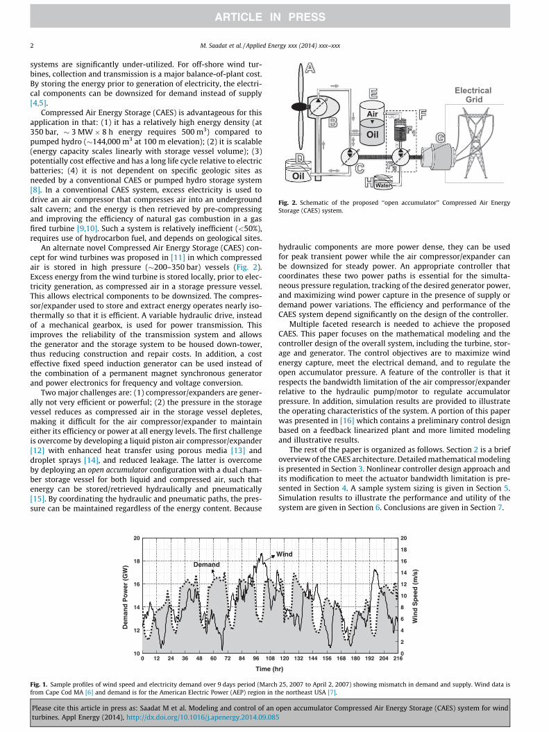
are often not available when the demand is high. For example,wind energy tends to be more abundant at night when powerdemand is low (Fig. 1). Variations in wind speed and solar intensitymake integrating wind and solar energy into the electric powergrid a challenge. An energy storage system can provide steadyand predictable power by storing excess energy and releasing itwhen the demand is greater than supply [1,2].
In this paper, we consider an energy storage concept for windturbines especially those that are off-shore. The capacity factor ofcurrent off-shore wind turbines are typically less than 50% [3] sothat the electrical generator and collection and transmission
r wind
Air
Oil W
ater
Oil Water
Electrical Grid
Fig. 2. Schematic of the proposed ‘‘open accumulator’’ Compressed Air EnergyStorage (CAES) system.
2 M. Saadat et al. / Applied Energy xxx (2014) xxx–xxx
systems are significantly under-utilized. For off-shore wind tur-bines, collection and transmission is a major balance-of-plant cost.By storing the energy prior to generation of electricity, the electri-cal components can be downsized for demand instead of supply[4,5].
Compressed Air Energy Storage (CAES) is advantageous for thisapplication in that: (1) it has a relatively high energy density (at350 bar, � 3 MW � 8 h energy requires 500 m3) compared topumped hydro (�144,000 m3 at 100 m elevation); (2) it is scalable(energy capacity scales linearly with storage vessel volume); (3)potentially cost effective and has a long life cycle relative to electricbatteries; (4) it is not dependent on specific geologic sites asneeded by a conventional CAES or pumped hydro storage system[8]. In a conventional CAES system, excess electricity is used todrive an air compressor that compresses air into an undergroundsalt cavern; and the energy is then retrieved by pre-compressingand improving the efficiency of natural gas combustion in a gasfired turbine [9,10]. Such a system is relatively inefficient (<50%),requires use of hydrocarbon fuel, and depends on geological sites.
An alternate novel Compressed Air Energy Storage (CAES) con-cept for wind turbines was proposed in [11] in which compressedair is stored in high pressure (�200–350 bar) vessels (Fig. 2).Excess energy from the wind turbine is stored locally, prior to elec-tricity generation, as compressed air in a storage pressure vessel.This allows electrical components to be downsized. The compres-sor/expander used to store and extract energy operates nearly iso-thermally so that it is efficient. A variable hydraulic drive, insteadof a mechanical gearbox, is used for power transmission. Thisimproves the reliability of the transmission system and allowsthe generator and the storage system to be housed down-tower,thus reducing construction and repair costs. In addition, a costeffective fixed speed induction generator can be used instead ofthe combination of a permanent magnet synchronous generatorand power electronics for frequency and voltage conversion.
Two major challenges are: (1) compressor/expanders are gener-ally not very efficient or powerful; (2) the pressure in the storagevessel reduces as compressed air in the storage vessel depletes,making it difficult for the air compressor/expander to maintaineither its efficiency or power at all energy levels. The first challengeis overcome by developing a liquid piston air compressor/expander[12] with enhanced heat transfer using porous media [13] anddroplet sprays [14], and reduced leakage. The latter is overcomeby deploying an open accumulator configuration with a dual cham-ber storage vessel for both liquid and compressed air, such thatenergy can be stored/retrieved hydraulically and pneumatically[15]. By coordinating the hydraulic and pneumatic paths, the pres-sure can be maintained regardless of the energy content. Because
10
12
14
16
18
20
Dem
and
Po
wer
(G
W)
Demand
Time (h
0 12 24 36 48 60 72 84 96 108
Fig. 1. Sample profiles of wind speed and electricity demand over 9 days period (Marchfrom Cape Cod MA [6] and demand is for the American Electric Power (AEP) region in t
Please cite this article in press as: Saadat M et al. Modeling and control of an oturbines. Appl Energy (2014), http://dx.doi.org/10.1016/j.apenergy.2014.09.085
hydraulic components are more power dense, they can be usedfor peak transient power while the air compressor/expander canbe downsized for steady power. An appropriate controller thatcoordinates these two power paths is essential for the simulta-neous pressure regulation, tracking of the desired generator power,and maximizing wind power capture in the presence of supply ordemand power variations. The efficiency and performance of theCAES system depend significantly on the design of the controller.
Multiple faceted research is needed to achieve the proposedCAES. This paper focuses on the mathematical modeling and thecontroller design of the overall system, including the turbine, stor-age and generator. The control objectives are to maximize windenergy capture, meet the electrical demand, and to regulate theopen accumulator pressure. A feature of the controller is that itrespects the bandwidth limitation of the air compressor/expanderrelative to the hydraulic pump/motor to regulate accumulatorpressure. In addition, simulation results are provided to illustratethe operating characteristics of the system. A portion of this paperwas presented in [16] which contains a preliminary control designbased on a feedback linearized plant and more limited modelingand illustrative results.
The rest of the paper is organized as follows. Section 2 is a briefoverview of the CAES architecture. Detailed mathematical modelingis presented in Section 3. Nonlinear controller design approach andits modification to meet the actuator bandwidth limitation is pre-sented in Section 4. A sample system sizing is given in Section 5.Simulation results to illustrate the performance and utility of thesystem are given in Section 6. Conclusions are given in Section 7.
Wind
r)
120 132 144 156 168 180 192 204 2160
2
4
6
8
10
12
14
16
18
20
Win
d S
pee
d (
m/s
)
25, 2007 to April 2, 2007) showing mismatch in demand and supply. Wind data ishe northeast USA [7].
pen accumulator Compressed Air Energy Storage (CAES) system for wind
0.02
0.020.02 0.02
0.02
0.02
0.2
0.2
0.2
0.2
0.2
0.3
0.3 0.3
0.4 0.40.45
Optimal Tip Speed Ratio ( *)
Tip Speed Ratio
Pit
ch A
ng
le (
deg
ree)
0 2 4 6 8 10 12 14 16 18 200
2
4
6
8
10
12
14
16
18
20
Fig. 3. Rotor power coefficient (Cp) as a function of blade pitch angle (b) and tipspeed ratio (k).
M. Saadat et al. / Applied Energy xxx (2014) xxx–xxx 3
2. System overview
The proposed CAES with an open accumulator architecture [15]is shown in Fig. 2. A variable displacement hydraulic pump (B)attached to the wind turbine rotor (A) in the nacelle converts windpower to hydraulic power. At down-tower (H), a variable displace-ment hydraulic pump/motor (C), a near-isothermal liquid pistonair compressor/expander (F) and a fixed speed induction generator(G) are connected in tandem on a common shaft. They are poweredby the pump (B) and exchange power with the storage vessel (E)with both liquid (hydraulic fluid) and compressed air at the samepressure. This allows energy to be stored in or extracted from (E)either hydraulically (as in a conventional hydraulic accumulator)or pneumatically (as in a conventional air receiver). In both cases,energy is stored in the compressed air. By coordinating the hydrau-lic and the pneumatic power paths, the pressure in (E) can bemaintained constant regardless of energy content, unlike a conven-tional closed hydraulic accumulator with only a hydraulic port or acompressed air receiver with only a pneumatic port. For example,as compressed air is being released from (E), some liquid can beadded to reduce the compressed air volume to maintain thepressure.
The pneumatic power branch makes better use of the vessel (E)volume than the hydraulic power branch (a compressed air tankstores 20 times more energy than a hydraulic accumulator at thesame peak pressure and total volume [15]) but hydraulic pump/motors are more power dense than the pneumatic compressor/expanders. This architecture can take advantage of both by utiliz-ing the hydraulic path to accommodate high power transientevents such as wind gust or sudden generation power demand,and reserving the pneumatic path for steady power.
The liquid piston air compressor/expander (F) consists of an aircompression/expansion chamber filled with porous media (F1), anda liquid piston pump/motor (F2). The porous material is used toincrease the heat transfer surface area [13,17,18]. A liquid piston(water) can flow through the porous material and provides a tightseal for the compressed air.1 Heat transfer can also be enhancedadditionally by water spray [14,19]. When storing energy pneumat-ically, the liquid piston pump/motor (F2) pumps water into the com-pression/expansion chamber, compressing the air within it. Heat ofcompression is transferred to the porous material and to the waterto maintain a near-isothermal operation. When the chamber pres-sure exceeds that of the storage vessel (E), the compressed air isejected and stored in the vessel. The chamber is then refreshed byreleasing the water and filling it with atmospheric air for the nextcycle. When retrieving energy, the compressed air is released intothe expansion chamber. As the air expands, the liquid pistonretreats, the liquid piston pump/motor (F2) is motored and work isderived. Heat is supplied from the porous material to maintain thetemperature of the expanding air.
3. Modeling
3.1. Wind turbine
A wind turbine extracts wind’s kinetic energy from the sweptarea of its rotor blades. The aerodynamic torque for a given windspeed Vw and rotor speed xr on the wind turbine shaft is givenby [20,21]:
Tw ¼12q0pR2
r CPðb; kÞV3
w
xrð1Þ
1 The water would ideally be taken from the sea or lake which are excellent heatreservoirs. However, filtering, cleanliness and corrosion issues need to be addressed.
Please cite this article in press as: Saadat M et al. Modeling and control of an oturbines. Appl Energy (2014), http://dx.doi.org/10.1016/j.apenergy.2014.09.085
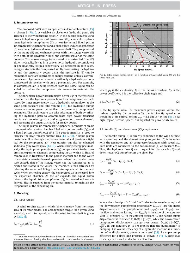
where q0 is the air density, Rr is the radius of turbine, CP is thepower coefficient, b is the collective pitch angle and
kðxr;VwÞ :¼ Rrxr
Vwð2Þ
is the tip speed ratio. For maximum power capture within theturbine capability (i.e. in region 2), the turbine tip speed ratioshould be at its optimal setting kopt ¼ 8:1 and b ¼ 0 (see Fig. 3). Athigh (region 3) wind speeds, b is adjusted for power curtailment.
3.2. Nacelle (B) and down-tower (C) pump/motors
The nacelle pump (B) is directly connected to the wind turbinewith speed xr and the down-tower pump/motor (C) is in serieswith the generator and air compressor/expander with speed xg .Both units are connected to the accumulator (E) at pressure Pacc.Thus, the hydraulic flow Q and torque T for the nacelle (B) anddown-tower (C) pump/motors are given by:
Qp ¼DpðtÞ
2pxr � LpðDp;xr ; rÞ ð3Þ
Tp ¼ �DpðtÞ
2pP0ðr � 1Þ � CpðDp;xr; rÞ ð4Þ
Qpm ¼DpmðtÞ
2pxg � LpmðDpm;xg ; rÞ ð5Þ
Tpm ¼ �DpmðtÞ
2pP0ðr � 1Þ � CpmðDpm;xg ; rÞ ð6Þ
where the subscripts ‘‘p ’’ and ‘‘pm’’ refer to the nacelle pump andthe downtowner pump/motor respectively, Dp=pmðtÞ are the inputdisplacements of the pump/motors and Lp=pmð�Þ and Cp=pmð�Þ arethe flow and torque losses, r :¼ Pacc=P0 is the ratio of the accumu-lator (E) pressure Pacc to the ambient pressure P0. The nacelle pumpdisplacement is restricted to DpðtÞ 2 ½0;Dmax
p � while the down-towerpump/motor displacement can go over center: DpmðtÞ 2 ½�Dmax
pm ;
Dmaxpm �. In our notation, D �x > 0 implies that the pump/motor is
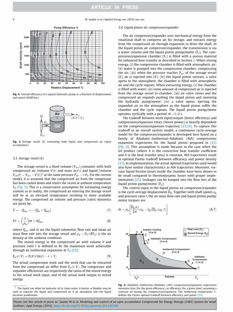
pumping. The overall efficiency of a hydraulic machine is a func-tion of its displacement, pressure and speed [22]. A sample pumpefficiency for a fixed line pressure is shown in Fig. 4. Note thatefficiency is reduced as displacement is low.
pen accumulator Compressed Air Energy Storage (CAES) system for wind
10
1010
30
3030
50
50
5050
7070
70
7070
80
80
80
80
85
85
85
85
90
9090
9095
95
95
Pump Efficiency %
Relative Displacement %
Sh
aft
Vel
oci
ty (
rpm
)
0 10 20 30 40 50 60 70 80 90 100
500
1000
1500
2000
2500
Fig. 4. Overall efficiency of a typical hydraulic pump as a function of displacementand speed (@200 bar).
Fig. 5. Storage vessel (E) containing both liquid and compressed air (openaccumulator).
Volume
Pre
ssu
re
rP0
P0
V0
V0/r
1
2
3
45
S 1S
2
AdiabaticCompression (1 to 2)
Isothermal Compression (2 to 3)
Adiabatic Compression (3 to 4)
Isobaric Cooling (4 to 5)
Heat Loss (S1)
Stored Energy (S2)
4 M. Saadat et al. / Applied Energy xxx (2014) xxx–xxx
3.3. Storage vessel (E)
The storage vessel is a fixed volume (Vacc) container with bothcompressed air (volume VðtÞ and mass mðtÞ) and liquid (volumeVoilðtÞ ¼ Vacc � VðtÞ)2 at the same pressure Pacc ¼ r P0. For the currentmodel, it is assumed that the compressed air from the compressorhas been cooled down and enters the vessel at ambient temperatureT0 (Fig. 5). This is a conservative assumption for estimating energycontent as in reality, the compressed air entering the storage vesselwill be at an elevated temperature resulting in more availableenergy. The compressed air volume and pressure (ratio) dynamicsare given by:
_V ¼ �Q acc ¼ � Q p þ Qpm
� �ð7Þ
V _r ¼ 1q0
� �_mþ rQ acc ð8Þ
where Qacc and _m are the liquid volumetric flow rate and mean airmass flow rate into the storage vessel and q0 ¼ P0=ðRT0Þ is the airdensity at the ambient condition.
The stored energy in the compressed air with volume V andpressure ratio r is defined to be the maximum work achievablethrough an isothermal expansion at T0 [23]:
Estðr;VÞ ¼ P0V r lnðrÞ � r þ 1ð Þ ð9Þ
The actual compression work and the work that can be extractedfrom the compressed air differ from Estðr;VÞ. The compressor andexpander efficiencies are respectively the ratios of the stored energyto the actual work input, and of the actual work output to storedenergy.
2 The liquid can either be hydraulic oil or clean water. A barrier or bladder may beused to separate the liquid and compressed air if air absorption into the liquidbecomes problematic.
Please cite this article in press as: Saadat M et al. Modeling and control of an oturbines. Appl Energy (2014), http://dx.doi.org/10.1016/j.apenergy.2014.09.085
3.4. Liquid piston air compressor/expander
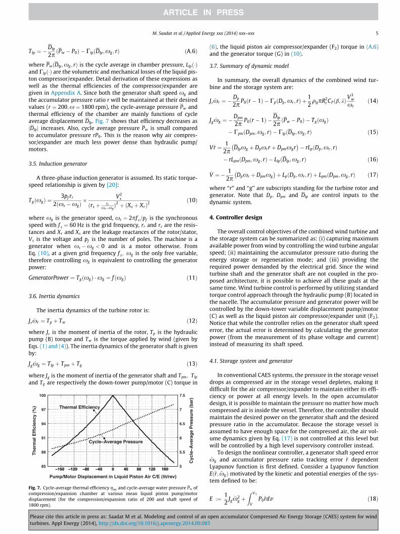
The air compressor/expander uses mechanical energy from therotational shaft to compress air for storage, and extracts energyfrom the compressed air through expansion to drive the shaft. Inthe liquid piston air compressor/expander, the transmission is viaa water column and the liquid piston pump/motor (F2). The com-pression/expansion chamber (F1) is filled with a porous materialfor enhanced heat transfer as described in Section 2. When storingenergy, (i) the compression chamber is filled with atmospheric air;(ii) water is pumped into the compression chamber, compressingthe air; (iii) when the pressure reaches Pacc of the storage vessel(E), air is injected into (E); (iv) the liquid piston retreats, a valveopens to the atmosphere, the chamber is filled with atmosphericair and the cycle repeats. When extracting energy, (i) the chamberis filled with water; (ii) some amount of compressed air is injectedfrom the storage vessel to chamber; (iii) air valve closes and thecompressed air expands pushing the liquid piston and motoringthe hydraulic pump/motor; (iv) a valve opens, ejecting theexpanded air to the atmosphere as the liquid piston refills thechamber and the cycle repeats. The liquid piston pump/motoroperates cyclically with a period of �1–2 s.
The tradeoff between work input/output (hence efficiency) andcompression/expansion times (hence power) is heavily dependenton the compression/expansion trajectory [23,24]. To capture thistradeoff in an overall system model, a continuous cycle-averagemodel for the compressor/expander is developed here based on afamily of Adiabatic–Isothermal–Adiabatic (AIA) compression/expansion trajectories for the liquid piston proposed in [23](Fig. 6). This assumption is made because in the case when thehA product (where h is the convective heat transfer coefficientand A is the heat transfer area) is constant, AIA trajectories resultin optimal Pareto tradeoff between efficiency and power density[23]. In implementation, the actual optimal trajectories used wouldalso have similar characteristics as AIA trajectories. Moreover, vis-cous liquid friction losses inside the chamber have been shown tobe small compared to thermodynamic losses with proper imple-mentation [25]. Leakages can be lumped into the flow loss of theliquid piston pump/motor (F2).
The control input to the liquid piston air compressor/expanderis the cycle average displacement Dlp. Together with shaft speed xg
and pressure ratio r, the air mass flow rate and liquid piston pump/motor torques are:
_m ¼ q0DlpðtÞ
2pxg � LlpðDlp;xg ; rÞ
" #ðA:7Þ
Fig. 6. Adiabatic–Isothermal–Adiabatic (AIA) compression/expansion trajectoriesminimize time (for the given efficiency), or efficiency (for a given time), assuming aconstant hA during the compression/expansion. The isothermal temperature T1
defines the Pareto optimal tradeoff between efficiency and power [23].
pen accumulator Compressed Air Energy Storage (CAES) system for wind
M. Saadat et al. / Applied Energy xxx (2014) xxx–xxx 5
Tlp ¼ �Dlp
2pðPw � P0Þ � ClpðDlp;xg ; rÞ ðA:6Þ
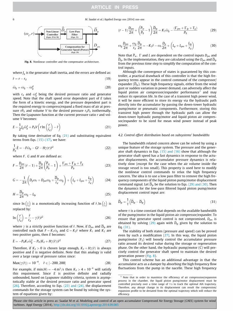
where PwðDlp;xg ; rÞ is the cycle average in chamber pressure, Llpð�Þand Clpð�Þ are the volumetric and mechanical losses of the liquid pis-ton compressor/expander. Detail derivation of these expressions aswell as the thermal efficiencies of the compressor/expander aregiven in Appendix A. Since both the generator shaft speed xg andthe accumulator pressure ratio r will be maintained at their desiredvalues (r ¼ 200;x ¼ 1800 rpm), the cycle-average pressure Pw andthermal efficiency of the chamber are mainly functions of cycleaverage displacement Dlp. Fig. 7 shows that efficiency decreases asjDlpj increases. Also, cycle average pressure Pw is small comparedto accumulator pressure rP0. This is the reason why air compres-sor/expander are much less power dense than hydraulic pump/motors.
3.5. Induction generator
A three-phase induction generator is assumed. Its static torque-speed relationship is given by [20]:
TgðxgÞ ¼3pf rr
2ðxs �xgÞ� V2
s
ðrs þ rrxs�xg
Þ2 þ ðXs þ XrÞ2ð10Þ
where xg is the generator speed, xs ¼ 2pf s=pf is the synchronousspeed with f s ¼ 60 Hz is the grid frequency, rr and rs are the resis-tances and Xr and Xs are the leakage reactances of the rotor/stator,Vs is the voltage and pf is the number of poles. The machine is agenerator when xs �xg < 0 and is a motor otherwise. FromEq. (10), at a given grid frequency f s; xg is the only free variable,therefore controlling xg is equivalent to controlling the generatorpower:
GeneratorPower ¼ TgðxgÞ �xg ¼ f ðxgÞ ð11Þ
3.6. Inertia dynamics
The inertia dynamics of the turbine rotor is:
Jr _xr ¼ Tp þ Tw ð12Þ
where Jr is the moment of inertia of the rotor, Tp is the hydraulicpump (B) torque and Tw is the torque applied by wind (given byEqs. (1) and (4)). The inertia dynamics of the generator shaft is givenby:
Jg _xg ¼ Tlp þ Tpm þ Tg ð13Þ
where Jg is the moment of inertia of the generator shaft and Tpm; Tlp
and Tg are respectively the down-tower pump/motor (C) torque in
Fig. 7. Cycle-average thermal efficiency gtm and cycle-average water pressure Pw ofcompression/expansion chamber at various mean liquid piston pump/motordisplacement (for the compression/expansion ratio of 200 and shaft speed of1800 rpm).
Please cite this article in press as: Saadat M et al. Modeling and control of an oturbines. Appl Energy (2014), http://dx.doi.org/10.1016/j.apenergy.2014.09.085
(6), the liquid piston air compressor/expander (F2) torque in (A.6)and the generator torque (G) in (10).
3.7. Summary of dynamic model
In summary, the overall dynamics of the combined wind tur-bine and the storage system are:
Jr _xr ¼ �Dp
2pP0ðr � 1Þ � CpðDp;xr ; rÞ þ
12q0pR2
r CPðb; kÞV3
w
xrð14Þ
Jg _xg ¼ �Dpm
2pP0ðr � 1Þ � Dlp
2pðPw � P0Þ � TgðxgÞ
� CpmðDpm;xg ; rÞ � ClpðDlp;xg ; rÞ ð15Þ
V _r ¼ 12p
Dlpxg þ Dpxrr þ Dpmxgr� �
� rLpðDp;xr; rÞ
� rLpmðDpm;xg ; rÞ � LlpðDlp;xg ; rÞ ð16Þ
_V ¼ � 12p
Dpxr þ Dpmxg� �
þ LpðDp;xr ; rÞ þ LpmðDpm;xg ; rÞ ð17Þ
where ‘‘r’’ and ‘‘g’’ are subscripts standing for the turbine rotor andgenerator. Note that Dp; Dpm and Dlp are control inputs to thedynamic system.
4. Controller design
The overall control objectives of the combined wind turbine andthe storage system can be summarized as: (i) capturing maximumavailable power from wind by controlling the wind turbine angularspeed; (ii) maintaining the accumulator pressure ratio during theenergy storage or regeneration mode; and (iii) providing therequired power demanded by the electrical grid. Since the windturbine shaft and the generator shaft are not coupled in the pro-posed architecture, it is possible to achieve all these goals at thesame time. Wind turbine control is performed by utilizing standardtorque control approach through the hydraulic pump (B) located inthe nacelle. The accumulator pressure and generator power will becontrolled by the down-tower variable displacement pump/motor(C) as well as the liquid piston air compressor/expander unit (F2).Notice that while the controller relies on the generator shaft speederror, the actual error is determined by calculating the generatorpower (from the measurement of its phase voltage and current)instead of measuring its shaft speed.
4.1. Storage system and generator
In conventional CAES systems, the pressure in the storage vesseldrops as compressed air in the storage vessel depletes, making itdifficult for the air compressor/expander to maintain either its effi-ciency or power at all energy levels. In the open accumulatordesign, it is possible to maintain the pressure no matter how muchcompressed air is inside the vessel. Therefore, the controller shouldmaintain the desired power on the generator shaft and the desiredpressure ratio in the accumulator. Because the storage vessel isassumed to have enough space for the compressed air, the air vol-ume dynamics given by Eq. (17) is not controlled at this level butwill be controlled by a high level supervisory controller instead.
To design the nonlinear controller, a generator shaft speed error~xg and accumulator pressure ratio tracking error ~r dependentLyapunov function is first defined. Consider a Lyapunov functionEð~r; ~xgÞmotivated by the kinetic and potential energies of the sys-tem defined to be:
E :¼ 12
Jg ~x2g þ
Z V1
VP0~rdv ð18Þ
pen accumulator Compressed Air Energy Storage (CAES) system for wind
Non-Linear Controller
(Eqns. 29 & 30)
Low-Pass Filter
(Eqn. 31)
Compensation for Generator Speed (Power)
(Eqn. 29)
( g, r)Dlp Dlp
Dpm
Fig. 8. Nonlinear controller and the compensator architecture.
3 Note that in order to maximize the efficiency of air compression/expansionprocess in the chamber, the liquid piston pump/motor displacement must becontrolled precisely over a time range of 1 s to track the optimal AIA trajectory.Therefore, any abrupt change in its displacement can result the compression/expansion profile to be deviated from the optimal trajectory which will reduce theefficiency.
6 M. Saadat et al. / Applied Energy xxx (2014) xxx–xxx
where Jg is the generator shaft inertia, and the errors are defined as:
~r ¼ r � rd ð19Þ
~xg ¼ xg �xdg ð20Þ
with rd and xdg being the desired pressure ratio and generator
speed. Note that the shaft speed error dependent part of E takesthe form of a kinetic energy, and the pressure dependent part isthe required energy to compress/expand a fixed mass of air at pres-sure rP0 and volume V to the desired pressure rdP0 isothermally.Then the Lyapunov function at the current pressure ratio r and vol-ume V becomes:
E ¼ 12
Jg ~x2g þ P0V r ln
rrd
� �� ~r
� �ð21Þ
By taking time derivative of Eq. (21) and substituting equivalentterms from Eqs. (15)–(17), we have:
1P0
_E ¼ �F ~xg � G~r � HcðrÞ~r2 ð22Þ
where F; G and H are defined as:
F ¼ Dpm
2p ðr � 1Þ þ Dlp
2pPw
P0� 1
!þ Cpm þ Clp þ Tg
P0ð23Þ
G ¼ � 12p
Dpxr þ Dpmxg þDlp
rdxg
!þ Lp þ Lpm þ
Llp
rd
� �ð24Þ
H ¼ Dlp
2pxg � Llp ð25Þ
since ln rrd
� �is a monotonically increasing function of ~r; ln r
rd
� �is
replaced by:
lnrrd
� �¼
~rrd� cð~rÞ~r2 ð26Þ
where c is a strictly positive function of ~r. Now, if Dpm and Dlp arecontrolled such that F ¼ K1 ~xg and G ¼ K2~r where K1 and K2 aretwo positive gains, then _E becomes:
_E ¼ �P0K1 ~x2g � P0 K2 þ Hcð~rÞð Þ~r2 ð27Þ
Therefore, if K2 > 0 is chosen large enough, K2 þ Hcð~rÞ is alwayspositive and _E is negative definite. Note that this analogy is validover a large range of pressure ratios since:
Max cð~rÞð Þ ¼ 10�4; ~r 2 ½�200;200� ð28Þ
For example, if minðHÞ ¼ �4 m3=s then K2 > 4� 10�4 will satisfythis requirement. Since E is positive definite and radiallyunbounded, based on Lyapunov stability criteria, system is asymp-totically stable at the desired pressure ratio and generator speed[26]. Therefore, according to Eqs. (23) and (24), the displacementcommands for the storage system can be found by solving the sys-tem of equations given by:
Please cite this article in press as: Saadat M et al. Modeling and control of an oturbines. Appl Energy (2014), http://dx.doi.org/10.1016/j.apenergy.2014.09.085
ðr � 1ÞDpm
2pþ Pw
P0� 1
!Dlp
2p¼ K1 ~xg �
ðCpm þ Clp þ TgÞP0
ð29Þ
xgDpm
2pþxg
rd
Dlp
2p¼ �K2~r �xr
Dp
2pþ Lp þ Lpm þ
Llp
rd
� �ð30Þ
Note that Pw; C and L are dependent on the control inputs Dpm andDlp. In the implementation, they are calculated using the Dpm and Dlp
from the previous time step to simplify the computation of the con-trol inputs.
Although the convergence of states is guaranteed by this con-troller, a practical drawback of this controller is that the high fre-quency terms appear in the control command of the compressor/expander (Dlp). These high frequency signals, either from the windgust or sudden variation in power demand, can adversely affect theliquid piston air compressor/expander performance3 and mayreduce its operation life. In the case of a transient high power wind,it will be more efficient to store its energy via the hydraulic pathdirectly into the accumulator by-passing the down-tower hydraulicpump/motor or pneumatic components. Furthermore, storing thistransient high power through the hydraulic path can allow thedown-tower hydraulic pump/motor and liquid piston air compres-sor/expander to be sized for mean wind power instead of peakpower.
4.2. Control effort distribution based on subsystems’ bandwidths
The bandwidth related concern above can be solved by using aunique feature of the storage system. The pressure and the gener-ator shaft dynamics in Eqs. (15) and (16) show that although thegenerator shaft speed has a fast dynamics in response to the actu-ator displacements, the accumulator pressure dynamics is rela-tively slow (except for the case when the air volume inside thestorage vessel is too small). This property is used here to modifythe nonlinear control commands to relax the high frequencyconcern. The idea is to use a low pass filter to remove the high fre-quency components of the liquid piston pump/motor displacementcommand signal. Let D̂lp be the solution to Eqs. (29) and (30). Thenthe dynamics for the low-pass filtered liquid piston pump/motordisplacement control input are:
_Dlp ¼1s
D̂lp � Dlp
� �ð31Þ
where s is a time constant that depends on the available bandwidthof the pump/motor in the liquid piston air compressor/expander. Toensure that generator speed control is not compromised, Dpm isobtained by solving (29) again with Dlp given by the solution toEq. (31).
The stability of both states (pressure and speed) can be provedeven by such a modification [27]. In this way, the liquid pistonpump/motor (F2) will loosely control the accumulator pressureratio around its desired value during the storage or regenerationphase. On the other hand, the hydraulic pump/motor (C) will pre-cisely control the generator shaft speed to maintain the desiredgeneration power (Fig. 8).
This control scheme has an additional advantage in that theaccumulator acts as a damper by absorbing the high frequency flowfluctuations from the pump in the nacelle. These high frequency
pen accumulator Compressed Air Energy Storage (CAES) system for wind
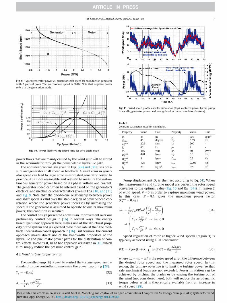
Fig. 9. Typical generator power vs. generator shaft speed for an induction generatorwith 2 pairs of poles. The synchronous speed is 60 Hz. Note that negative powerrefers to the generation mode.
Fig. 10. Power factor vs. tip speed ratio for zero pitch angle.
Fig. 11. Wind speed profile used for simulation (top); captured power by the pumpin nacelle, generator power and energy level in the accumulator (bottom).
Table 1Constant parameters used for simulation.
Property Value Unit Property Value Unit
Rr 45 m Jr 2e6 kg m2
bmax 40 degree Xb 0.03 Hz
xratedr
20.5 rpm rd 200 –
f s 60 Hz pf 2 –Vs 415 volt hA 59 kW/K
Dratedp
440 l/rev Xp 0.5 Hz
Dratedpm
5 l/rev Xpm 0.5 Hz
Dratedlp
125 l/rev Xlp 0.005 Hz
Jg 20 kg m2 Vacc 670 m3
M. Saadat et al. / Applied Energy xxx (2014) xxx–xxx 7
power flows that are mainly caused by the wind gust will be storedin the accumulator through the power-dense hydraulic path.
The nonlinear control law given in Eqs. (29) and (30) uses pres-sure and generator shaft speed as feedback. A small error in gener-ator speed can lead to large error in estimated generator power. Inpractice, it is more reasonable and realistic to measure the instan-taneous generator power based on its phase voltage and current.The generator speed can then be inferred based on the generator’selectrical and mechanical characteristics given in Eqs. (10) and (11)and Fig. 9. Note that the one-to-one relationship between powerand shaft speed is valid over the stable region of power-speed cor-relation where the generator power increases by increasing thespeed. If the generator is assumed to operate below its maximumpower, this condition is satisfied.
The control design presented above is an improvement over ourpreliminary control design in [16] in several ways. The energybased Lyapunov approach here makes use of the structural prop-erty of the system and is expected to be more robust than the feed-back linearization based approach in [16]. Furthermore, the currentapproach makes direct use of the bandwidth properties of thehydraulic and pneumatic power paths for the distribution of con-trol efforts. In contrast, an ad hoc approach was taken in [16] whichis to simply reduce the pressure control gain.
4.3. Wind turbine torque control
The nacelle pump (B) is used to control the turbine speed via thestandard torque controller to maximize the power capturing [28]:
Tp ¼ �Ksx2r ð32Þ
Ks ¼12q0pR5
r
Cmaxp
k�3 ð33Þ
Please cite this article in press as: Saadat M et al. Modeling and control of an oturbines. Appl Energy (2014), http://dx.doi.org/10.1016/j.apenergy.2014.09.085
Pump displacement Dp is then set according to Eq. (4). Whenthe measurements and turbine model are perfect, the rotor speedconverges to the optimal value (Fig. 10 and Eq. (34)). In region 2of wind speed, b ¼ 0 in order to capture maximum wind power.In this case, k� ¼ 8:1 gives the maximum power factor(Cmax
P ¼ 0:48).
_xr ¼1
2Jrq0pR5
r x2r
Cp
k3 �Cmax
p
k�3
!ð34Þ
)Cp <
Cmaxp
k�3 k3 ) _xr < 0
Cp >Cmax
p
k�3 k3 ) _xr > 0
8>><>>:
Speed regulation of rotor at higher wind speeds (region 3) istypically achieved using a PID controller:
bðtÞ ¼ Kp ~xrðtÞ þ KI
Z t
0
~xrðsÞdsþ KDd ~xrðtÞ
dtð35Þ
where ~xr ¼ xr �xdr is the rotor speed error, the difference between
the desired rotor speed and the measured rotor speed. In thisregion, the primary objective is to limit the turbine power so thatsafe mechanical loads are not exceeded. Power limitation can beachieved by pitching the blades or by yawing the turbine out ofthe wind (not considered here), both will reduce the aerodynamictorque below what is theoretically available from an increase inwind speed [28].
pen accumulator Compressed Air Energy Storage (CAES) system for wind
196
197
198
199
200
201
202
Acc
um
ula
tor
Pre
ssu
re R
atio
Pressure Ratio
Displacement
0 6 12 18 24 30 36 42 48 54 60 66 720
150
300
450
600
750
900
Dis
pla
cem
ent
(lit
/rev
)
0
5
10
15
20
25
Tu
rbin
e A
ng
ula
r S
pee
d (
rpm
)
Generator
Turbine
Time (hr)
0 6 12 18 24 30 36 42 48 54 60 66 721804
1805
1806
1807
1808
1809
Gen
erat
or
An
gu
lar
Sp
eed
(rp
m)
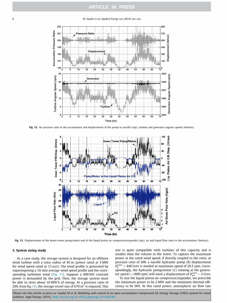
Fig. 12. Air pressure ratio in the accumulator and displacement of the pump in nacelle (top); turbine and generator angular speeds (bottom).
Fig. 13. Displacements of the down-tower pump/motor and of the liquid piston air compressor/expander (top); air and liquid flow rates to the accumulator (bottom).
8 M. Saadat et al. / Applied Energy xxx (2014) xxx–xxx
5. System sizing study
As a case study, the storage system is designed for an offshorewind turbine with a rotor radius of 45 m (power rated at 3 MWfor wind speed rated at 12 m/s). The wind profile is generated bysuperimposing a 10-min average wind speed profile and the corre-sponding turbulent wind (Fig. 11). Suppose a 600 kW constantpower is demanded by the grid. Then, the storage system mustbe able to store about 16 MW h of energy. At a pressure ratio of200, from Eq. (9), the storage vessel size of 670 m3 is required. This
Please cite this article in press as: Saadat M et al. Modeling and control of an oturbines. Appl Energy (2014), http://dx.doi.org/10.1016/j.apenergy.2014.09.085
size is quite compatible with turbines of this capacity and issmaller than the volume in the tower. To capture the maximumpower at the rated wind speed, if directly coupled to the rotor, atpressure ratio of 200, a nacelle hydraulic pump (B) displacementDrated
p ¼ 440 l/rev is needed at maximum speed of 20.5 rpm. Corre-spondingly, the hydraulic pump/motor (C) rotating at the genera-tor speed (�1800 rpm) will need a displacement of Drated
pm ¼ 5 l/rev.To size the liquid piston air compressor/expander, we prescribe
the maximum power to be 2 MW and the minimum thermal effi-ciency to be 90%. At this rated power, atmospheric air flow rate
pen accumulator Compressed Air Energy Storage (CAES) system for wind
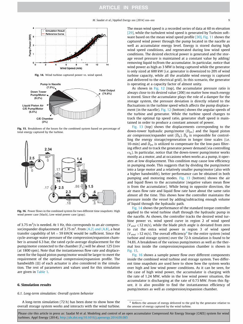
Fig. 14. Wind turbine captured power vs. wind speed.
Total Output(74.8%)
Pump in Nacelle(7.5%)
C/E Chamber(3%)
Down TowerPump/Motor
(8.2%)
Liquid Piston AirC/E Pump/Motor
(6.5%)
Fig. 15. Breakdown of the losses for the combined system based on percentage oftotal energy captured by the turbine.
2.5
0
2.34
0
.17
.16
2.5 .17 2.3 .6
.18
1.4
.9
.6
1.5 .86
Fig. 16. Power flows in the combined system for two different time snapshots: Highwind power case (black), Low wind power case (gray).
M. Saadat et al. / Applied Energy xxx (2014) xxx–xxx 9
of 3.75 m3/s is needed. At 1 Hz, this corresponds to an air compres-sor/expander displacement of 3.75 m3. From (A.2) and (A.8), a heattransfer capability of hA ¼ 59 kW/K would be sufficient. Since thecycle-average water pressure of the compression/expansion cham-ber is around 6.3 bar, the rated cycle-average displacement for thepump/motor connected to the chamber (F2) will be about 125 l/rev(at 1800 rpm). Note that the instantaneous flow rate and displace-ment for the liquid piston pump/motor would be larger to meet therequirement of the optimal compression/expansion profile. Thebandwidth (X) of each actuator is also considered in the simula-tion. The rest of parameters and values used for this simulationare given in Table 1.
4 Reflects the amount of energy delivered to the grid by the generator relative tothe amount of energy captured by the wind turbine.
6. Simulation results
6.1. Long-term simulation: Overall system behavior
A long-term simulation (72 h) has been done to show how theoverall storage system works and interacts with the wind turbine.
Please cite this article in press as: Saadat M et al. Modeling and control of an oturbines. Appl Energy (2014), http://dx.doi.org/10.1016/j.apenergy.2014.09.085
The mean wind speed is a recorded series of data at 60 m elevation[29], while the turbulent wind speed is generated by Turbsim soft-ware based on the mean wind speed profile [30]. Fig. 11 shows thecaptured wind power through the pump located in the nacelle aswell as accumulator energy level. Energy is stored during highwind speed conditions, and regenerated during low wind speedconditions. The desired electrical power is generated and the stor-age vessel pressure is maintained at a constant value by adding/removing liquid to/from the accumulator. In particular, notice thatwind power as high as 3 MW is being captured while the generatoris only sized at 600 kW (i.e. generator is downsized to 20% of windturbine capacity, while all the available wind energy is capturedand delivered to the electrical grid). In this scenario, the generatoris operating at a capacity factor of almost unity.
As shown in Fig. 12 (top), the accumulator pressure ratio isalways close to its desired value (200) no matter how much energyis stored. Since the accumulator plays the role of a damper for thestorage system, the pressure deviation is directly related to thefluctuations in the turbine speed which affects the pump displace-ment (in the nacelle). Fig. 12 (bottom) shows the angular speeds ofthe turbine and generator. While the turbine speed changes totrack the optimal tip speed ratio, generator shaft speed is main-tained in order to produce a constant amount of power.
Fig. 13 (top) shows the displacements corresponding to thedown-tower hydraulic pump/motor (Dpm) and the liquid pistonair compressor/expander unit (Dlp). Dlp is responsible for control-ling the energy storage/regeneration in longer time scales (i.e.10-min) and Dpm is utilized to compensate for the low-pass filter-ing effect and to track the generator power demand (via controllingxg). In particular, notice that the down-tower pump/motor worksmostly as a motor, and at occasions when works as a pump, it oper-ates at low displacement. This condition may cause low efficiencyin pumping mode. This suggests that by dividing the pump/motorinto a large motor and a relatively smaller pump/motor (also witha higher bandwidth), better performance can be obtained in bothpumping and motoring modes. Fig. 13 (bottom) shows the airand liquid flows to the accumulator (negative values mean flowis from the accumulator). While being in opposite direction, theair mass flow rate and liquid flow rate have about the same ratioalmost all the time. This shows how the controller maintains thepressure inside the vessel by adding/subtracting enough volumeof liquid through the hydraulic path.
Fig. 14 shows the performance of the standard torque controllerapplied to the wind turbine shaft through the hydraulic pump inthe nacelle. As shown, the controller tracks the desired wind tur-bine power vs. wind speed curve in region 2 of wind speed(Vwind 612 m/s), while the blade pitch angle is deviated from zeroto cut the extra wind power in region 3 of wind speed(Vwind >12 m/s). The overall efficiency4 for the entire system (windturbine and storage system) over the 72-h simulation is found to be74.8%. A breakdown of the various pump/motors as well as the ther-mal loss inside the compression/expansion chamber is shown inFig. 15.
Fig. 16 shows a sample power flow over different componentsinside the combined wind turbine and storage system. Two differ-ent time snapshots are used here to show how the system worksover high and low wind power conditions. As it can be seen, forthe case of high wind power, the accumulator is charging withthe rate of 1.24 MW, while in the low wind power situation, theaccumulator is discharging at the rate of 0.73 MW. From this fig-ure, it is also possible to find the instantaneous efficiency ofpump/motors as well as compression/expansion chamber.
pen accumulator Compressed Air Energy Storage (CAES) system for wind
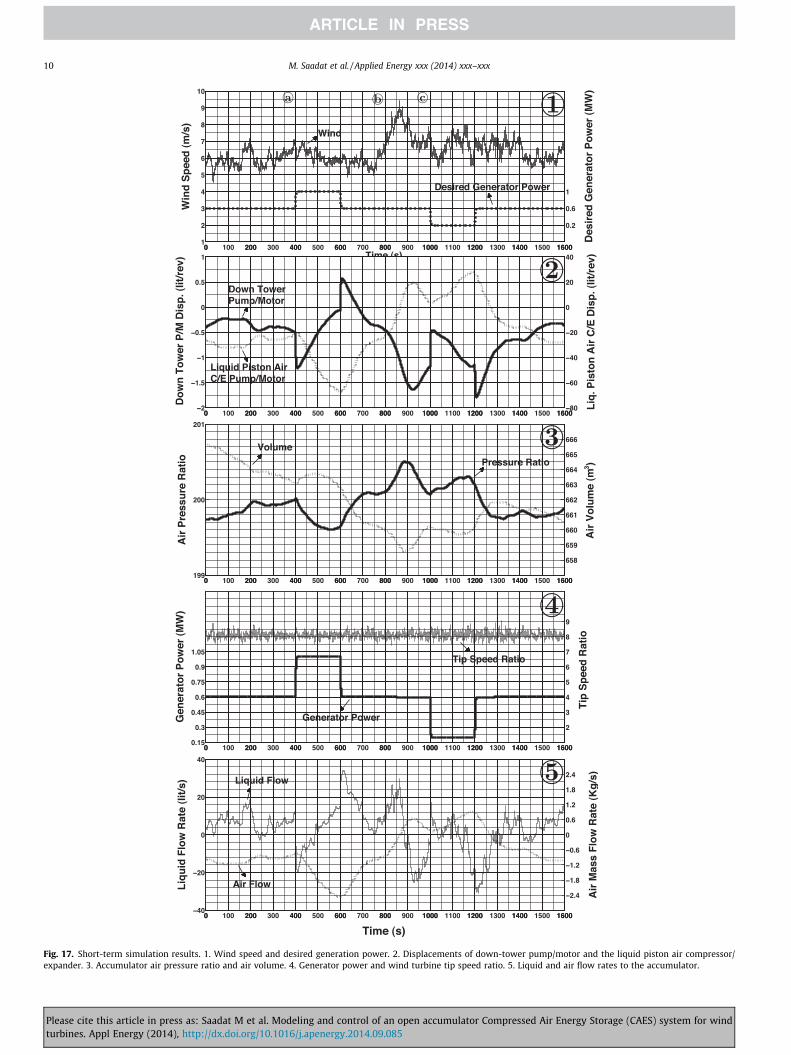
Fig. 17. Short-term simulation results. 1. Wind speed and desired generation power. 2. Displacements of down-tower pump/motor and the liquid piston air compressor/expander. 3. Accumulator air pressure ratio and air volume. 4. Generator power and wind turbine tip speed ratio. 5. Liquid and air flow rates to the accumulator.
10 M. Saadat et al. / Applied Energy xxx (2014) xxx–xxx
Please cite this article in press as: Saadat M et al. Modeling and control of an open accumulator Compressed Air Energy Storage (CAES) system for windturbines. Appl Energy (2014), http://dx.doi.org/10.1016/j.apenergy.2014.09.085
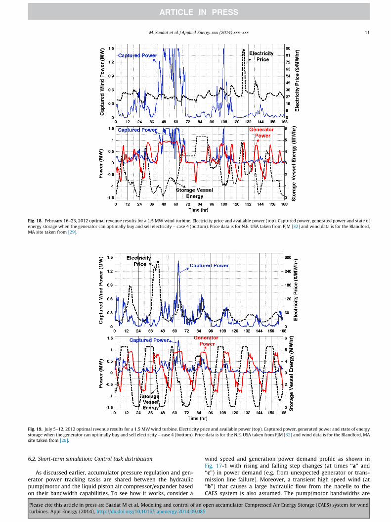
Fig. 18. February 16–23, 2012 optimal revenue results for a 1.5 MW wind turbine. Electricity price and available power (top). Captured power, generated power and state ofenergy storage when the generator can optimally buy and sell electricity – case 4 (bottom). Price data is for N.E. USA taken from PJM [32] and wind data is for the Blandford,MA site taken from [29].
Fig. 19. July 5–12, 2012 optimal revenue results for a 1.5 MW wind turbine. Electricity price and available power (top). Captured power, generated power and state of energystorage when the generator can optimally buy and sell electricity – case 4 (bottom). Price data is for the N.E. USA taken from PJM [32] and wind data is for the Blandford, MAsite taken from [29].
M. Saadat et al. / Applied Energy xxx (2014) xxx–xxx 11
6.2. Short-term simulation: Control task distribution
As discussed earlier, accumulator pressure regulation and gen-erator power tracking tasks are shared between the hydraulicpump/motor and the liquid piston air compressor/expander basedon their bandwidth capabilities. To see how it works, consider a
Please cite this article in press as: Saadat M et al. Modeling and control of an oturbines. Appl Energy (2014), http://dx.doi.org/10.1016/j.apenergy.2014.09.085
wind speed and generation power demand profile as shown inFig. 17-1 with rising and falling step changes (at times ‘‘a’’ and‘‘c’’) in power demand (e.g. from unexpected generator or trans-mission line failure). Moreover, a transient high speed wind (at‘‘b’’) that causes a large hydraulic flow from the nacelle to theCAES system is also assumed. The pump/motor bandwidths are
pen accumulator Compressed Air Energy Storage (CAES) system for wind
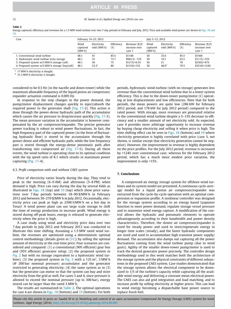
Table 2Energy captured, efficiency and revenues for a 1.5 MW wind turbine over two 7-day periods in February and July, 2012. Price and available wind power are shown in Figs. 18 and19.
Case February 16–23, 2012 July 5–12, 2012
Windcaptured(MW h)
Electricitysold (MW h)
Efficiency(%)
Revenue ($)/%increase overcase 1
Windcaptured(MW h)
Electricitysold (MW h)
Efficiency(%)
Revenue ($)/%increase overcase 1
1. Conventional wind turbine 48.1 41 85.5 $1140 30 25.6 85.5 $15602. Hydrostatic wind turbine w/no storage 48.1 35 72.7 $965.5/�15% 30 19.1 63.5 $1172/–25%3. Proposed system w/3 MW h storage (sell) 48.1 36 75 $1215/+6.5% 30 21 70 $2303/+47%4. Proposed system w/3 MW h storage (buy/sell) 48.1 52.3a 80 $1310/+15% 30 48.6b 79.5 $3510/+124%
a 17 MW h electricity is bought.b 31.3 MW h electricity is bought.
12 M. Saadat et al. / Applied Energy xxx (2014) xxx–xxx
considered to be 0.5 Hz (in the nacelle and down-tower) while themaximum allowable frequency of the liquid piston air compressor/expander actuation command is 0.005 Hz.
In response to the step changes in the power demand, thepump/motor displacement changes quickly to inject/absorb therequired power to the generator shaft (Fig. 17-2). This action isdone through the power-dense hydraulic path of the accumulatorwhich causes the air pressure to drop/increase quickly (Fig. 17-3).The mean pressure variation in the accumulator is however com-pensated by the air compressor/expander. The precise generatorpower tracking is robust to wind power fluctuations. In fact, thehigh frequency part of the captured power (in the form of fluctuat-ing hydraulic flow) is stored in the accumulator through thepower-dense and efficient hydraulic path, while the low frequencypart is stored through the energy-dense pneumatic path aftertransforming into compressed air (Fig. 17-5). During all theseevents, the wind turbine is operating close to its optimal conditionwith the tip speed ratio of 8.1 which results in maximum powercapturing (Fig. 17-4).
6.3. Profit comparison with and without CAES system
Price of electricity varies hourly during the day. They tend topeak in the morning (6–9 AM) and afternoon (5–8 PM) whendemand is high. Price can vary during the day by several folds asillustrated in Figs. 18 (top) and 19 (top) which show price varia-tions over 7 day periods between 18–90 $/MW h in February2012 and between 30–270 $/MW h in July 2012. Occasionally, elec-tricity price can peak as high as 2500 $/MW h on a hot day inTexas! A wind power plant can use large scale storage to shiftthe time of energy production to increase profit. Wind energy isstored during off-peak hours, energy is released to generate elec-tricity when the price is high.
A case study using wind and electricity price data over two7 day periods in July 2012 and February 2012 was conducted toillustrate this time shifting. Assuming a 1.5 MW rated wind tur-bine, the revenues are optimized using a deterministic optimalcontrol methodology (details given in [31]) by selling the optimalamount of electricity at the real-time price. Four scenarios are con-sidered and compared: (1) a conventional (90% efficient) gear boxand (95% efficient) generator setup; (2) the proposed system inFig. 2 but with no storage (equivalent to a hydrostatic wind tur-bine); (3) the proposed system in Fig. 2 with a 125 m3, 3 MW h(@ 200 bar nominal pressure) accumulator and the generatorrestricted to generating electricity; (4) the same system as in (3)but the generator can motor so that the system can buy and storeelectricity from the grid as well. For cases 3 and 4, since pressure isallowed to exceed the nominal pressure (up to 300 bar), energystored can be larger than the rated 3 MW h.
The results are summarized in Table 2. The optimal operationsfor case 4 are shown in Figs. 18 (bottom) and 19 (bottom). For both
Please cite this article in press as: Saadat M et al. Modeling and control of an oturbines. Appl Energy (2014), http://dx.doi.org/10.1016/j.apenergy.2014.09.085
periods, hydrostatic wind-turbine (with no storage) generates lessrevenue than the conventional wind turbine due to a lower systemefficiency. This is due to the down-tower pump/motor (C) operat-ing at low displacements and low efficiencies. Note that for bothperiods, the mean powers are quite low (286 kW for February2012 period, and 178 kW for July 2012 period) compared to therated power. With storage, more revenues are generated relativeto the conventional wind turbine despite a 5–15% decrease in effi-ciency and a smaller amount of net electricity sold. As expected,case 4 provides more arbitrage opportunity to increase revenueby buying cheap electricity and selling it when price is high. Thetime shifting effect can be seen in Figs. 18 (bottom) and 19 whereelectricity generation is highly correlated with price (case 3, notshown, is similar except that electricity generation cannot be neg-ative). However, the improvement in revenue is highly dependenton the price profiles. For the July 2012 period, revenue is increasedby +124% over conventional case; whereas for the February 2012period, which has a much more modest price variation, theimprovement is only +15%.
7. Conclusions
A compressed air energy storage system for offshore wind tur-bines and its system model are presented. A continuous cycle-aver-age model for a liquid piston air compressor/expander wasextracted from the cycle-by-cycle operation with an optimal com-pression or expansion profile. A nonlinear controller was designedfor the storage system according to an energy based Lyapunovfunction to meet power demand, regulate storage vessel pressureand to maximize wind energy capture. A modification of the con-trol allows the hydraulic and pneumatic elements to operateadvantageously according to their bandwidth and power densitycharacteristics. Therefore, the slower air compressor/expander issized for steady power and used to store/regenerate energy inlonger time scales (steady), and the faster hydraulic componentsare sized and used to accommodate high transient power supply/demand. The accumulator also damps out capturing all the powerfluctuations coming from the wind turbine pump (due to windgusts). Agility of the smaller down-tower pump/motor is used totrack the desired generator power precisely. The controller designmethodology used in this work matches both the architecture ofthe storage system and the physical constraints of different subsys-tems in the proposed CAES system. Case studies demonstrated thatthe storage system allows the electrical component to be down-sized to 1/5 of the turbine’s capacity while capturing all the avail-able wind energy and delivering a constant mean electrical power.The CAES can also aid grid integration and load matching, and toincrease profit by selling electricity at higher prices. This can leadto wind energy becoming a dispatchable base power source toreplace fossil-fuel.
pen accumulator Compressed Air Energy Storage (CAES) system for wind
M. Saadat et al. / Applied Energy xxx (2014) xxx–xxx 13
Acknowledgements
This work is supported by the National Science Foundationunder Grant EFRI 1038294 and the Institute for Renewable Energyand Environments (IREE) at the University of Minnesota underGrant RM-0027-11.
Appendix A. Cycle-average model for liquid piston aircompressor/expander unit
In this appendix, we derive the cycle average compressed airmass flow rate _m and liquid piston pump/motor (F2) torque Tlp.Both quantities are averaged over a compression/expansion cycle(�1–2 s) and defined at a given common shaft speed xg , storagevessel pressure ratio r :¼ Pacc=P0, and cycle average displacementDlp of the liquid piston pump/motor F2 which is the control input.
Within the compression/expansion cycle, the liquid piston flowrate varies to achieve an Adiabatic–Isothermal–Adiabatic (AIA) tra-jectory as in Fig. 6. The family of AIA trajectories is parameterizedby T1, the temperature of the isothermal segment. For compres-sion, T1 P T0, and for expansion T1 6 T0. The final temperature isgiven by Tf ¼ T2
1=T0. Different choices of T1 result in differentpower and efficiency as T1 deviates from the ambient temperatureT0, power increases but efficiency decreases. However, for a givenheat transfer capability of the compressor/expander, specified byhA [W/K] (product of heat transfer coefficient and heat transferarea), the achieved efficiency (or power) is optimal at that power(or efficiency).
The time it takes to compress/expand a given mass of air withan optimal AIA trajectory specified by T1 can be calculated as [23]:
_m ¼ hA 1� T0=T1j jR 2c
c�1 ln T0T1
� � lnðrÞ
� � ðA:1Þ
where r is the pressure ratio, and þ=� signs correspond to compres-sion (T1 > T0) and expansion (T1 < T0). Let Qlp be the cycle averageliquid piston flow rate. Since _m ¼ q0 � Qlp where q0 ¼ P0=ðRT0Þ is theair density at ðP0; T0Þ, we have
Q lp ¼hA 1� T0=T1j j
q0R 2cc�1 ln T0
T1
� � lnðrÞ
� � ðA:2Þ
On the other hand, we can express Qlp in terms of the cycle-averageflow rate of the liquid piston pump/motor and leakage as:
Q lp ¼DlpðtÞ
2pxg � L0lpðT1;xg ; rÞ ðA:3Þ
where Dlp is the cycle average displacement of the liquid pistonpump/motor (F2), L0lpðT1;xg ; rÞ represents the volumetric losses in(F2) and in the compression/expansion chamber (F1). By equating(A.2) and (A.3), we can solve for T1 in terms of ðDlp;xg ; rÞ. Thus,hence forth, we shall consider the liquid piston pump/motor dis-placement Dlp as the control input the compressor/expander andthe corresponding AIA trajectory with isothermal temperatureT1ðDlp;xg ; rÞ will be to be used within the cycle.
The P–V work required to compress/expand a unit mass of airto/from pressure ratio r with an AIA trajectory specified by T1
including the isobaric final ejection/initial injection is given by[23]:
EaðT1; rÞ ¼ RT0�
cc� 1
T1
T0
� �2
� 2T1
T0ln
T1
T0
� �� 1
" #þ T1
T0lnðrÞ
!ðA:4Þ
Cycle-average chamber pressure Pw is defined based on the princi-ple of virtual work: ðPw � P0Þ � Qlp ¼ Ea � _m
Please cite this article in press as: Saadat M et al. Modeling and control of an oturbines. Appl Energy (2014), http://dx.doi.org/10.1016/j.apenergy.2014.09.085
Pw :¼ q0EaðT1; rÞ þ P0 ðA:5Þ
Generally Pw r � P0 since a large portion of the compression/expansion trajectory is at low pressure. For example, whenr ¼ 200; Pw 6 7:5 in Fig. 7. This is the main reason air compressor/expanders are much less power dense than hydraulic pump/motors.Given ðDlp;xg ; rÞ, the cycle average liquid piston pump/motortorque Tlp and air mass flow rate are given as:
Tlp ¼ �Dlp
2pðPw � P0Þ � ClpðDlp;xg ; rÞ ðA:6Þ
_m ¼ q0DlpðtÞ
2p xg � LlpðDlp;xg ; rÞ !
ðA:7Þ
where ClpðDlp;xg ; rÞ captures mechanical losses in the pump/motorand in the liquid piston, and PwðDlp;xg ; rÞ is given by Eqs. (A.5) andLlpðDlp;xg ; rÞ ¼ L0lpðT1;xg ; rÞ in Eq.(A.3) with T1 corresponding toðDlp;xg ; rÞ. The thermal efficiency of the compression/expansionprocess is defined as the ratio between the stored energy in theair (including the ejection/injection work) and the total compres-sion/expansion work (Ea):
gtm ¼lnðrÞ
cc�1
T1T0
� �2� 1� 2 T1
T0ln T1
T0
� �� �þ T1
T0lnðrÞ
0BB@
1CCA1
ðA:8Þ
where þ=� signs correspond to compression and expansion modes.
References
[1] Powell KM, Hedengren JD, Edgar TF. Dynamic optimization of a solar thermalenergy storage system over a 24 hour period using weather forecasts. In:Proceedings of the 2013 American control conference, Washington DC; 2013.
[2] Borhan H, Rotea MA, Viassolo D. Optimization-based power management of awind farm with battery storage. J Wind Energy 2012;16:1197–211.
[3] Musial W, Butterfield S. Future for offshore wind energy in the united states.Tech rep NREL/CP-500-36313. National Renewable Energy Laboratory Report;2004.
[4] Johnson JX, Kleine RD, Keoleian GA. Assessment of energy storage fortransmission-constrained wind. Appl Energy 2014;124:377–88.
[5] Capuder T, Pandzic H, Kuzle I, Skrlec D. Specifics of integration of wind powerplants into the croatian transmission network. Appl Energy 2013;101:142–50.
[6] Renewable Energy Research Laboratory (RERL). University of MassachusettsAmherst. Wind Speed Data for the Highland Center. Truro, Cape Cod site.<http://www.umass.edu/windenergy/resourcedata.Truro.php> [cited05.08.14].
[7] PJM Open Access Data. Hourly load data for the american electric power (AEP)region; 2014. <http://www.pjm.com/markets-and-operations/energy/real-time/loadhryr.aspx> [cited 05.08.14].
[8] Katsaprakakis D, Christakis D, Pavlopoylos K, Stamataki S, Dimitrelou I,Stefanakis I, et al. Introduction of a wind powered pumped storage systemin the isolated insular power system of Karpathos–Kasos. Appl Energy 2012;97:38–48.
[9] Kim H-M, Rutqvist J, Ryu D-W, Choi B-H, Sunwoo C, Song W-K. Exploring theconcept of compressed air energy storage (CAES) in lined rock caverns atshallow depth: a modeling study of air tightness and energy balance. ApplEnergy 2012;92:653–67.
[10] Raju M, Khaitan SK. Modeling and simulation of compressed air storage incaverns: a case study of the Huntorf plan. Appl Energy 2012;89(1):474–81.
[11] Li PY, Loth E, Simon TW, de Ven JDV, Crane SE. Compressed air energy storagefor offshore wind turbines. In: Proceedings of the 2011 international fluidpower exhibition (IFPE), Las Vegas, NV; 2011.
[12] de Ven JDV, Li PY. Liquid piston gas compression. Appl Energy 2009;86(10):2183–91.
[13] Zhang C, Simon TW, Li PY. Optimization of the axial porosity distribution ofporous inserts in a liquid piston gas compressor using a one-dimensionalformulation. In: ASME-IMECE-2013, no. #63862; 2013.
[14] Qin C, Loth E. Liquid piston compression with droplet heat transfer. In:Proceedings of the 51st AIAA aerospace sciences meeting; 2013.
[15] Li PY, de Ven JV, Sancken C. Open accumulator concept for compact fluidpower energy storage. In: Proceedings of the ASME international mechanicalengineering congress, Seattle, WA; 2007.
[16] Saadat M, Li PY. Modeling and control of a novel compressed air energy storagemodeling and control of a novel compressed air energy storage system foroffshore wind turbine. In: Proceedings of the 2012 American controlconference, Montreal, Canada; 2012. p. 3032–7.
pen accumulator Compressed Air Energy Storage (CAES) system for wind
14 M. Saadat et al. / Applied Energy xxx (2014) xxx–xxx
[17] Sozen M, Kuzay TM. Enhanced heat transfer in round tubes with porousinserts. Int J Heat Fluid Flow 1996;17(2):124–9.
[18] Zhang C, Saadat M, Li PY, Simon T. Heat transfer in a long, thin tube section ofan air compressor: an empirical correlation from CFD and a thermodynamicmodeling. In: Proceedings of the 2012 ASME international mechanicalengineering congress, Houston, TX, no. #86673; 2012.
[19] Saadat M, Shirazi FA, Li PY. Modeling and trajectory optimization of waterspray cooling in a liquid piston air compressor. In: Proceedings of the 2013ASME summer heat transfer conference; 2013.
[20] Anaya-Lara O, Jenkins M, Ekanayake J, Cartwright P, Hughes M. Wind energygeneration-modeling and control. John Wiley & Sons, Inc.; 2009.
[21] Spera DA. Wind turbine technology – fundamental concepts. 2nd ed. ASMEPress; 2009.
[22] Merritt HE. Hydraulic control systems. John Wiley & Sons, Inc.; 1991.[23] Sancken CJ, Li PY. Optimal efficiency-power relationship for an air motor/
compressor in an energy storage and regeneration system. In: Proceedings ofthe 2009 ASME dynamic systems and control conference, Hollywood, USA;2009. p. 1315–22.
[24] Rice AT, Li PY. Optimal efficiency-power tradeoff for an air motor/compressorwith volume varying heat transfer capability. In: Proceedings of the 2011ASME dynamic systems and control conference, Arlington, VA; 2011.
Please cite this article in press as: Saadat M et al. Modeling and control of an oturbines. Appl Energy (2014), http://dx.doi.org/10.1016/j.apenergy.2014.09.085
[25] Saadat M, Li PY, Simon TW. Optimal trajectories for a liquid piston compressor/expander in a compressed air energy storage system with consideration ofheat transfer and friction. In: Proceedings of the 2012 American controlconference, Montreal, Canada; 2012. p. 1800–5.
[26] Slotine J-JE. Applied nonlinear control. Prentice-Hall; 1991.[27] Wang M, Li PY. Displacement control of hydraulic actuators using a passivity
based nonlinear controller. In: Proceedings of the 2012 dynamic systems andcontrol conference, Ft. Lauderdale, FL, no. #8784; 2012.
[28] Pao LY, Johnson KE. A tutorial on the dynamics and control of wind turbinesand wind farms. In: Proceedings of the 2009 American control conference, St.Louis, MO; 2009.
[29] Renewable Energy Research Laboratory (RERL). University of MassachusettsAmherst, Wind Speed Data for the Blandford, Western MA site. <http://www.umass.edu/windenergy/downloads/data/Blandford_2012_07-01_2012-09-30.dat> [cited 05.08.14].
[30] NREL. TurbSim user’s guide for version 1.40; September 2008.[31] Saadat M, Shirazi FA, Li PY. Revenue maximization of electricity generation for
a wind turbine integrated with a compressed air energy storage system. In:Proceedings of the 2014 American control conference, Portland, OR; 2014.
[32] PJM Open Access Data; 2014. <http://www.pjm.com/markets-and-operations/energy/real-time/lmp.aspx> [cited 05.08.14].
pen accumulator Compressed Air Energy Storage (CAES) system for wind