Embed Size (px)
Citation preview
International Journal of Electrical, Electronics and Data Communication, ISSN: 2320-2084 Volume- 1, Issue- 8, Oct-2013
Modeling And Analysis Of Distributed Power Flow Controller Based On Reliability Of The Transmission System
40
MODELING AND ANALYSIS OF DISTRIBUTED POWER FLOW CONTROLLER BASED ON RELIABILITY OF THE TRANSMISSION
SYSTEM
1K.VENKATA NAGARAJU, 2N.C. KOTAIAH
M.tech Student Scholar, Department of Electrical & Electr onics Engineering, R.V.R & J.C.College of Engineering, Chowdavaram, Guntur, A.P, India
Associate Professor, Department of Electrical & Electronics Engineering, R.V.R & J.C.College of Engineering, Chowdavaram, Guntur, A.P, India
E-mail: [email protected], [email protected]
Abstract- This paper presents a new component called Distributed Power Flow Controller (DPFC) is one of the devices within the FACTS family. DPFC is derived from the UPFC with an eliminated common DC link. The UPFC control the active power exchange between the shunt and series converter that are through the common DC link connecting between them but now the active power exchange between the shunt and series converter, which is through the transmission line at the 3rd harmonic frequency in the DPFC. The DPFC can be designed with multiple single phase series converters (D-FACTS) and one three phase shunt converter. The reliability of the DPFC system is further improved by the use of multiple single phase series converters with the adapted control schemes. The DPFC having much control capability like UPFC, however at much reduced cost and an improved reliability. The DPFC comprises the adjustment of the transmission line parameters i.e. impedance of the line, the transmission angle, and the bus voltage. The principle of operation and analysis of the DPFC are presented in this paper and the corresponding simulation results are also shown. Keywords—Power Flow Control, Flexible AC Transmission System, Current Control, symmetrical component, Voltage Source Converter, Power-transmission control, Distributed Power Flow Controller, Unified Power Flow Controller. I. INTRODUCTION Nowadays the power system becomes very complex due to the increasing load demand of the electricity and the aging of the networks. There is a great desire for the power flow control in the transmission lines with fast operation and reliability [1]. All the FACTS devices can be utilized for the control of power flow in the transmission system. UPFC (Unified Power Flow Controller) shown in Fig.1, is one of the power flow controller in the FACTS family, which can control the transmission line impedance, transmission angle and bus voltage [2].
Fig.1. simplified representation of a UPFC The UPFC having both the series and shunt
converter with a commonly coupled DC link is used for bidirectional power flow. The series converter acts as a static synchronous series compensator (SSSC) and the shunt converter acts as a static synchronous compensator (STATCOM).
The basic function of series converter injects the
voltage into the transmission line with controllable magnitude and phase angle. The injected voltage acts as a synchronous AC voltage source which varies both the transmission angle and line impedance. The modified transmission angle and line impedance independently influences the active and reactive power injection or absorption between the series converter and transmission line. The UPFC is controlled to provide active and reactive series compensation without an external energy source [3].The reactive power is generated internally by series converter [4] and the active power is supplied by the shunt converter that is transported through the common DC link.
The main function of the shunt converter (STATCOM) is to supply or absorb the active power demand by the series converter (SSSC). The shunt converter controls the voltage of the DC capacitor by absorbing or supplying active power from the grid. The shunt converter can also provide reactive compensation for the grid [5].Considering its control capability; the UPFC can have the basic functions:
Voltage regulation Series reactive compensation Phase shifting
The listed functions of the UPFC can be
executed simultaneously, which makes the UPFC the most powerful power flow controlling device (PFCD).
International Journal of Electrical, Electronics and Data Communication, ISSN: 2320-2084 Volume- 1, Issue- 8, Oct-2013
Modeling And Analysis Of Distributed Power Flow Controller Based On Reliability Of The Transmission System
41
The devices used in UPFC with high voltage and current rating are quite expensive, which limits its practical applications.
The Distributed Power Flow Controller (DPFC) is one of the device with in FACTS family, which is derived from the UPFC. As compared with the UPFC, DPFC has the same controlling capability to change all the parameters within the transmission system. In case of DPFC the commonly connected DC link between series and shunt converter is eliminated and application of D-FACTS [6] concept to series converter shown in Fig.2.The active power exchange between the converters is at 3rd harmonic frequency. The D-FACTS concept not only reduces the ratings of the devises but also improves the reliability of the system because of redundancy and reducing the cost of high voltage isolation.
The reliability of the DPFC is improved because of the redundancy of the series converters before failure. If any one of the series converters fails, that will stop voltage injecting into the transmission line and the other series converter units will continue the operation. The performance of DPFC is improved by considering better control scheme during the series converter failure. The control schemes adapted for dpfc corresponding simulation results before and after the failure of any one series converter unit are also presented.
Fig.2. DPFC configuration.
II. DPFC PRINCIPLE The DPFC is derived from the UPFC by considering two approaches as follows. First, eliminating commonly connected dc link of UPFC, second distributing series converter with D-FACTS concept to series converter, which consists of multiple units that are connected in series with the transmission lines as shown in Fig.3.
Fig. 3. Flow chart from UPFC to DPFC. The distributed series converter can inject a voltage with controllable magnitude and phase angle
over 3600. The shunt converter injects the harmonic currents to the grid and provides active power required for the series converter units. In case of UPFC the active power exchange takes place between the series and shunt converter through common dc link freely. While maintaining the same control capability as that of UPFC the dc link between the converters is eliminated.
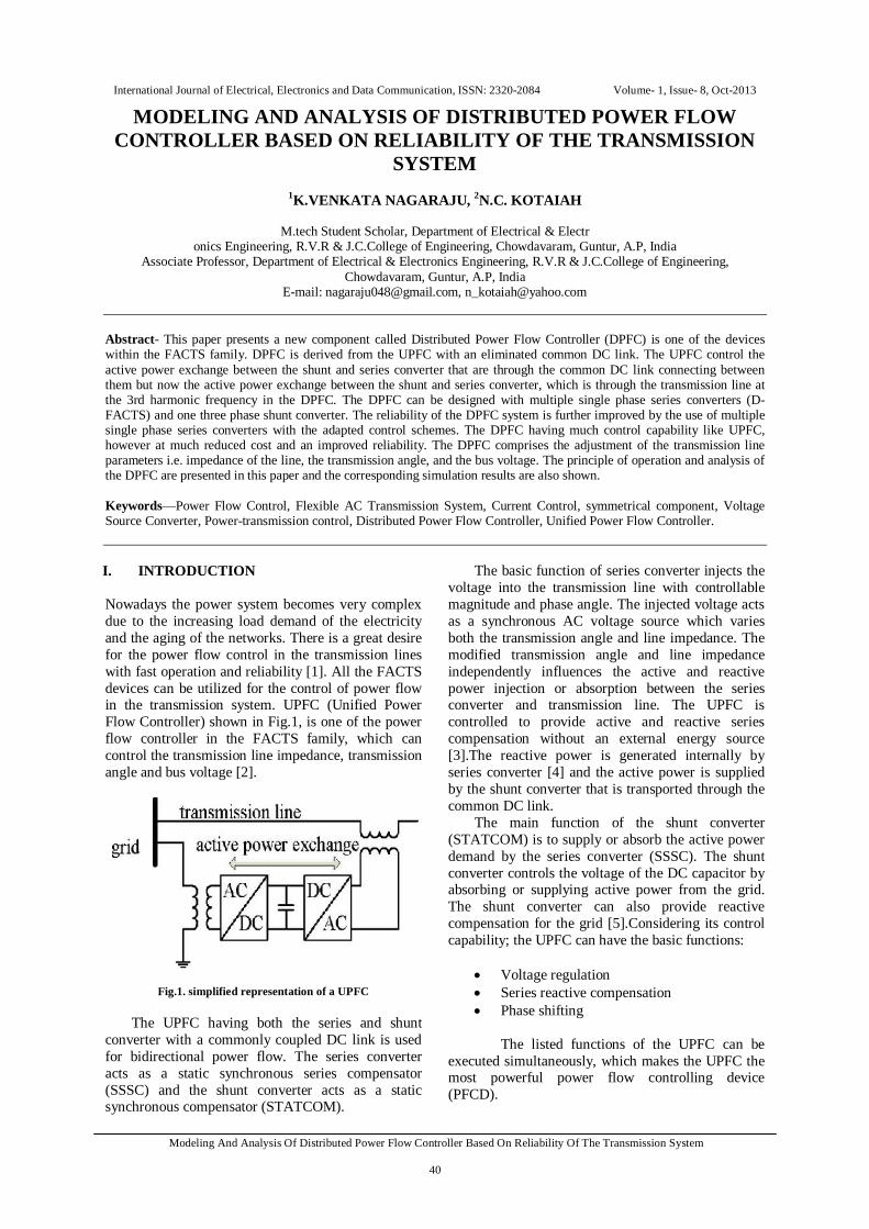
Fig.4 Active power exchange between DPFC converters. With in the DPFC, transmission line is acting as a common connection to exchange the active power between the ac terminals of series and shunt converter, as shown in Fig.4. According to the Fourier analysis, a nonsinusoidal voltage and current can be expressed as sum of sinusoidal functions with different amplitudes in different frequencies. The active power is defined as the mean value of the product of voltage and current. Since the integrals of all the cross product of terms with different frequencies are zero, the active power can be expressed by:
푃 = 푉∞
퐼 cos∅ (1)
where Vi and Ii are the voltage, current at the i th harmonic frequency and Φi is the angle between voltage and current. The active power at different frequencies is isolated from each other and the voltage or current at one frequency does not influence the active power at other frequencies. The independency of the active power at different frequencies gives the opportunity that a converter without power source can generate active power at one frequency and absorbs other frequencies. The shunt converter can absorb active power from the grid at fundamental frequency and injects currents into the grid at harmonic frequency. Similarly the series converter injects the voltages into the grid at fundamental frequency and absorbs the active power from the grid at harmonic frequency. The 3rd harmonic is selected to exchange the active power between the converters through transmission line because it is a zero sequence harmonic that can easily blocked by the use of Υ-Δ transformers, which are used for change the voltage levels. The high pass filters are used to allow the

International Journal of Electrical, Electronics and Data Communication, ISSN: 2320-2084 Volume- 1, Issue- 8, Oct-2013
Modeling And Analysis Of Distributed Power Flow Controller Based On Reliability Of The Transmission System
42
harmonic currents and blocks the fundamental currents. The concept of D-FACTS is to use multiple numbers of controllers with low rating instead of one large rated controller. This will improve the reliability and reduce the cost of high voltage isolation between phases. III. ANALYSIS OF THE DPFC In this section the steady state behavior of the DPFC before series converter failure is analyzed and the controlling capability of the DPFC is expressed in terms of both the transmission network and DPFC parameters. This section starts with simplification of the DPFC and then analyzed of the circuit at the fundamental and 3rd harmonic frequency.
Fig. 5. DPFC simplified representation.
To simplify the DPFC, the shunt and multiple series converters are replaced by voltage sources at different frequencies in series with the line impedance. It is represented by two series connected controllable ac voltage sources at fundamental and third harmonic frequency.
The simplified repof the DPFC is shown in Fig.5.The DPFC is placed in a two-bus system with the sending end and the receiving end voltages as Vs and Vr respectively. The transmission line is replaced by an inductance L with the line current I. All the series converters of the DPFC are injected at the fundamental frequency voltage Vse,1 and at the third harmonic frequency voltage Vse,3. The shunt converter is fed to the sending bus with the inductor Lsh. and generate the voltages Vsh,1 and Vsh,3 . The current injected by the shunt converter into the sending is Ish. The active and reactive power flow at the receiving end is Pr and Qr.
For an easier analysis, based on the superposition theorem, the simplified representation of the DPFC can be further simplified by being split into
fundamental frequency circuit and third harmonic frequency circuit, as shown in Fig.6.
Fig. 6. DPFC equivalent circuit. (a) Fundamental frequency. (b) Thirdharmonic frequency.
A. Fundamental Frequency Circuit
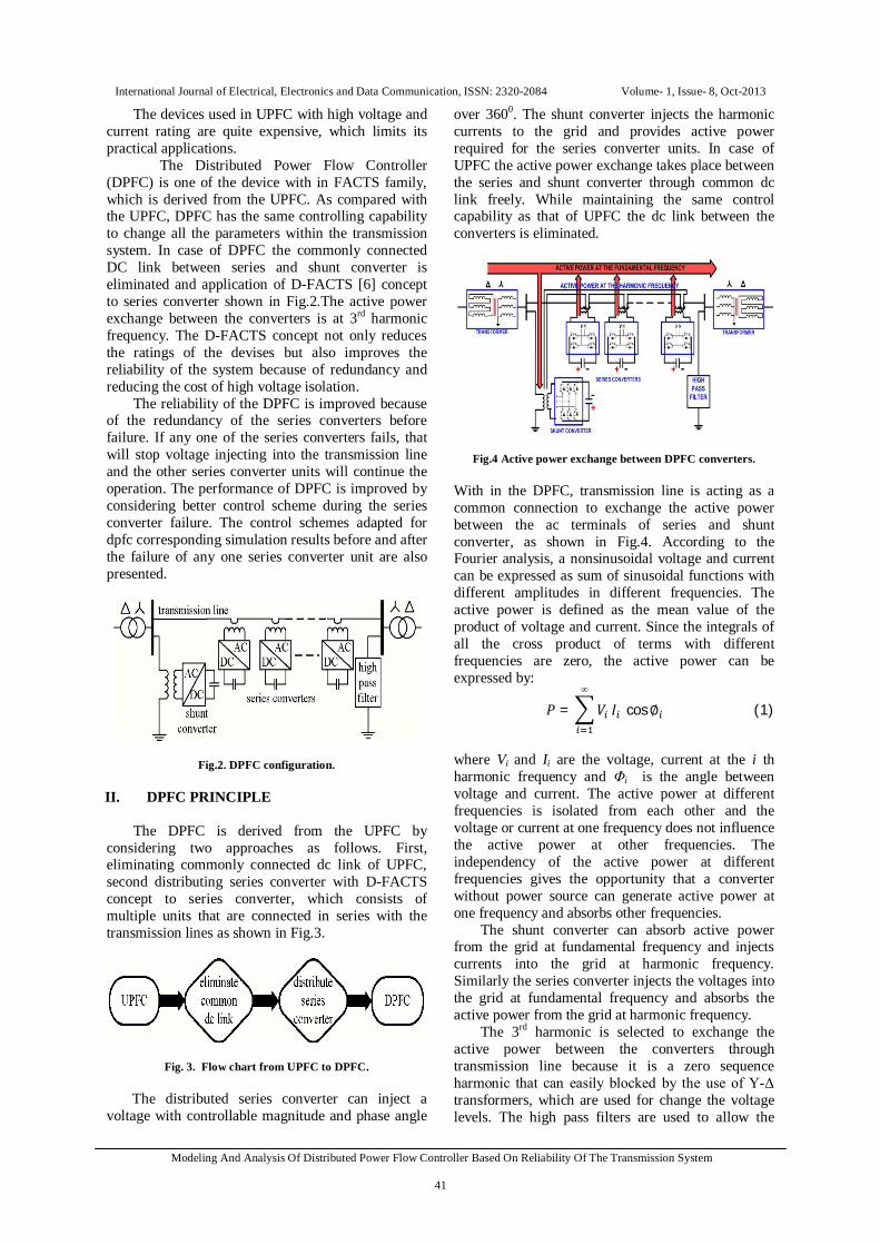
In this case the DPFC circuit is analyzed at fundamental frequency. The control capability of the DPFC is examined and the relationship between control range and the exchanged active power is found. The power flow control capability of the DPFC can be illustrated by the active power Pr and reactive power Qr at the receiving end as shown in Fig.7. The behavior of the DPFC is similar to that of UPFC, the active and reactive power flows are expressed as follows:
where Pr0 ,Qr0 are the active, reactive power flow, and θ is the transmission angle of the uncompensated system. The locus of the power flow without the DPFC compensation f (Pr0,Qr0 ) is a circle with the radius of |V |2/|X1| around the center in the PQ-plane. Each point of this circle gives the Pr0 and Qr0 values of the uncompensated system at the transmission angle θ. The control range of Pr and Qr is obtained from a complete rotation of the voltage Vse,1 with its maximum magnitude. Fig. 6.Shows the control ranges of the DPFC with the transmission angle θ.
The active power required by the series converter as follows:
where Φr0 is the power angle at the receiving end of the uncompensated system.
International Journal of Electrical, Electronics and Data Communication, ISSN: 2320-2084 Volume- 1, Issue- 8, Oct-2013
Modeling And Analysis Of Distributed Power Flow Controller Based On Reliability Of The Transmission System
43
Fig. 7. DPFC active and reactive power control range with the
transmission angle θ. The maximum active power is obtained with the following equation: where
crS , is the control range of the DPFC, which
is given by crcrcr jQPS ,,, max
Accordingly, the control range of the DPFC is proportional to the maximum of the active power exchange.Fig.8. Illustrate the maximum active power requirement of the series converters.
Fig. 8. Maximum active power requirement of the series converters.
B. Third harmonic Frequency Circuit:
The third harmonic component within the DPFC system is used to generate active and reactive
power between the series and shunt converters. The observed active and reactive power at 3rd harmonic frequency can be expressed as:
푃 , =푉 , 푉 ,
푋 ′sin휃 (6)
푄 , =푉 ,
푋 ′ 푉 , cos휃 − 푉 , (7)
and 푉 , = 푉 , cos휃
Substituting the value of 푉 , in equation (6) gives
푃 , =푉 ,
푋 ′cos θ sin휃 (8)
The maximum voltage of the series converters at the third harmonic frequency should fulfill the following condition:
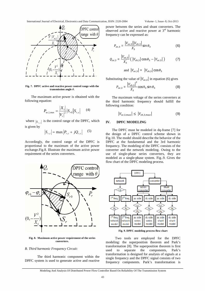
푉 , , ≤ 푉 , , (9) IV. DPFC MODELING The DPFC must be modeled in dq-frame [7] for the design of a DPFC control scheme shown in Fig.10. The model should describe the behavior of the DPFC at the fundamental and the 3rd harmonic frequency. The modeling of the DPFC consists of the converter and the network modeling. Owing to the use of single-phase series converters, they are modeled as a single-phase system. Fig..9. Gives the flow chart of the DPFC modeling process.
Fig. 9. DPFC modeling process flow chart
Two tools are employed for the DPFC modeling: the superposition theorem and Park’s transformation [8]. The superposition theorem is first used to separate the components, Park’s transformation is designed for analysis of signals at a single frequency and the DPFC signal consists of two frequency components. Park’s transformation is
crrr
se SSVX
P ,021
max,1, (4)
(5)
International Journal of Electrical, Electronics and Data Communication, ISSN: 2320-2084 Volume- 1, Issue- 8, Oct-2013
Modeling And Analysis Of Distributed Power Flow Controller Based On Reliability Of The Transmission System
44
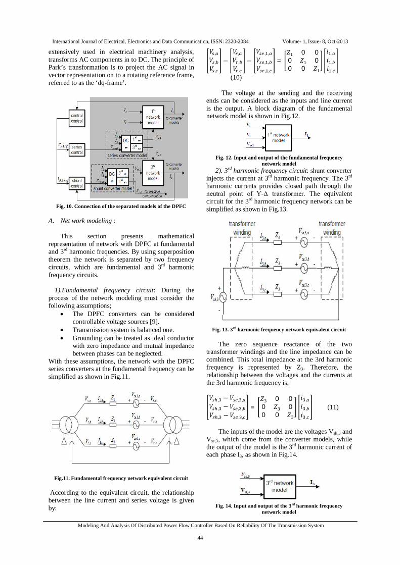
extensively used in electrical machinery analysis, transforms AC components in to DC. The principle of Park’s transformation is to project the AC signal in vector representation on to a rotating reference frame, referred to as the ‘dq-frame’.
Fig. 10. Connection of the separated models of the DPFC
A. Net work modeling :
This section presents mathematical
representation of network with DPFC at fundamental and 3rd harmonic frequencies. By using superposition theorem the network is separated by two frequency circuits, which are fundamental and 3rd harmonic frequency circuits.
1).Fundamental frequency circuit: During the
process of the network modeling must consider the following assumptions;
The DPFC converters can be considered controllable voltage sources [9].
Transmission system is balanced one. Grounding can be treated as ideal conductor
with zero impedance and mutual impedance between phases can be neglected.
With these assumptions, the network with the DPFC series converters at the fundamental frequency can be simplified as shown in Fig.11.
Fig.11. Fundamental frequency network equivalent circuit According to the equivalent circuit, the relationship between the line current and series voltage is given by:
푉 ,푉 ,푉 ,
−푉 ,푉 ,푉 ,
−푉 , ,푉 , ,푉 , ,
=푍 0 00 푍 00 0 푍
푖 ,푖 ,푖 ,
(10)
The voltage at the sending and the receiving ends can be considered as the inputs and line current is the output. A block diagram of the fundamental network model is shown in Fig.12.
Fig. 12. Input and output of the fundamental frequency
network model 2). 3rd harmonic frequency circuit: shunt converter
injects the current at 3rd harmonic frequency. The 3rd harmonic currents provides closed path through the neutral point of Υ-Δ transformer. The equivalent circuit for the 3rd harmonic frequency network can be simplified as shown in Fig.13.
Fig. 13. 3rd harmonic frequency network equivalent circuit
The zero sequence reactance of the two
transformer windings and the line impedance can be combined. This total impedance at the 3rd harmonic frequency is represented by Z3. Therefore, the relationship between the voltages and the currents at the 3rd harmonic frequency is: 푉 , − 푉 , ,푉 , −푉 , ,푉 , −푉 , ,
=푍 0 00 푍 00 0 푍
푖 ,푖 ,푖 ,
(11)
The inputs of the model are the voltages Vsh,3 and
Vse,3, which come from the converter models, while the output of the model is the 3rd harmonic current of each phase I3, as shown in Fig.14.
Fig. 14. Input and output of the 3rd harmonic frequency
network model

International Journal of Electrical, Electronics and Data Communication, ISSN: 2320-2084 Volume- 1, Issue- 8, Oct-2013
Modeling And Analysis Of Distributed Power Flow Controller Based On Reliability Of The Transmission System
45
B. Series converter modeling :
The series converter is PWM control single-phase converter, which is identical. The AC side and the DC side voltages of the series converter are Vse and Vse,DC respectively and refV,sef is the modulation amplitude of the reference AC signal in pu, which is generated by the series control. The AC voltages consist of fundamental and the 3rd harmonic frequency components. Their relationship can be illustrated as follows:
푉 = 푉 , + 푉 , (12)
1). AC side modeling: The AC side voltage of the
converter can be approximated with the product of the AC reference signal and the DC voltage as Vse:
푉 = 푟푒푓 .푉 , (13)
By applying the super- position theorem to the equation, equation (13) can be separated into: 푉 ,푉 ,
=푟푒푓 , ,푟푒푓 , ,
.푉 , (14)
The input signals of the AC side model of the series converter is refV,se and Vse,dc and the output is the AC voltage Vse, which comes from the DC side model.
2). DC side modeling: The DC voltage of the series converter Vdc,se is related with the DC current Idc,se and the relationship is given by: 퐶 , = 퐼 , (15) The DC side current of the series converter is approximated to: 퐼 , = 푟푒푓 . 퐼 = 푟푒푓 , , + 푟푒푓 , , . ( 퐼 + 퐼 ) (16) Accordingly, the input signals for the DC side model are 푟푒푓 , , , 푟푒푓 , , , 퐼 푎푛푑 퐼 , and the output is the DC voltage Vse,dc. By combining the models of the AC side and the DC side, the series converter model is shown in Fig.15.
Fig. 15. Block diagram of the series converter model
C. Shunt converter modeling: The shunt converter consists of a three-phase converter that is back-to-back connected to a single-phase converter. Similar as a STATCOM, the three phase converter is connected to the low-voltage side of the Y-Δ transformer to absorb active power from the grid. The single-phase converter is connected between the ground and the neutral point of the Y- Δ transformer to inject 3rd harmonic current. The simplified model of the shunt converter is shown in Fig.16.
1). AC side modeling: AC voltage can be approximately written as follows:
푉 , = 푟푒푓 , , .푉 , (17) 푉 , = 푟푒푓 , , .푉 , (18)
2). DC side modeling: The capacitor DC voltage of
the shunt converter is given with the following equation: 퐶 , = 퐼 , , − 퐼 , , (19) By applying Park’s transformation to the fundamental frequency components, the DC current at the three-phase side can be found: 퐼 , , = 푟푒푓 , , , . 퐼 , , + 푟푒푓 , , , . 퐼 , , ) (20)
Fig. 16. Block diagram of the shunt converter model
V. DPFC CONTROLLERS
To control the multiple converters, DPFC consists of different types of controllers: they are central controller, shunt controller and series controller, as shown in Fig.17.
Fig. 17. DPFC control block diagram.
International Journal of Electrical, Electronics and Data Communication, ISSN: 2320-2084 Volume- 1, Issue- 8, Oct-2013
Modeling And Analysis Of Distributed Power Flow Controller Based On Reliability Of The Transmission System
46
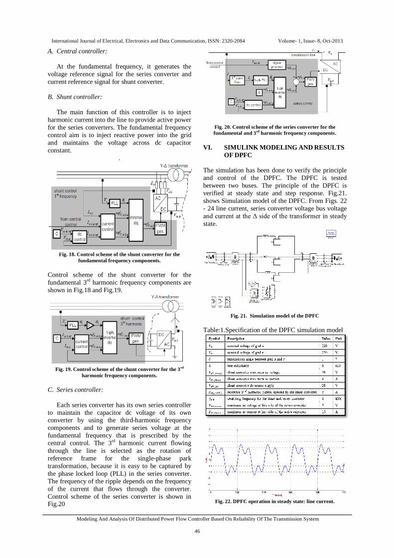
A. Central controller: At the fundamental frequency, it generates the voltage reference signal for the series converter and current reference signal for shunt converter. B. Shunt controller: The main function of this controller is to inject harmonic current into the line to provide active power for the series converters. The fundamental frequency control aim is to inject reactive power into the grid and maintains the voltage across dc capacitor constant.
.
Fig. 18. Control scheme of the shunt converter for the
fundamental frequency components. Control scheme of the shunt converter for the fundamental 3rd harmonic frequency components are shown in Fig.18 and Fig.19.
Fig. 19. Control scheme of the shunt converter for the 3rd
harmonic frequency components. C. Series controller: Each series converter has its own series controller to maintain the capacitor dc voltage of its own converter by using the third-harmonic frequency components and to generate series voltage at the fundamental frequency that is prescribed by the central control. The 3rd harmonic current flowing through the line is selected as the rotation of reference frame for the single-phase park transformation, because it is easy to be captured by the phase locked loop (PLL) in the series converter. The frequency of the ripple depends on the frequency of the current that flows through the converter. Control scheme of the series converter is shown in Fig.20
Fig. 20. Control scheme of the series converter for the fundamental and 3rd harmonic frequency components.
VI. SIMULINK MODELING AND RESULTS
OF DPFC The simulation has been done to verify the principle and control of the DPFC. The DPFC is tested between two buses. The principle of the DPFC is verified at steady state and step response. Fig.21. shows Simulation model of the DPFC. From Figs. 22 - 24 line current, series converter voltage bus voltage and current at the Δ side of the transformer in steady state.
Fig. 21. Simulation model of the DPFC
Table:1.Specification of the DPFC simulation model
Fig. 22. DPFC operation in steady state: line current.
International Journal of Electrical, Electronics and Data Communication, ISSN: 2320-2084 Volume- 1, Issue- 8, Oct-2013
Modeling And Analysis Of Distributed Power Flow Controller Based On Reliability Of The Transmission System
47
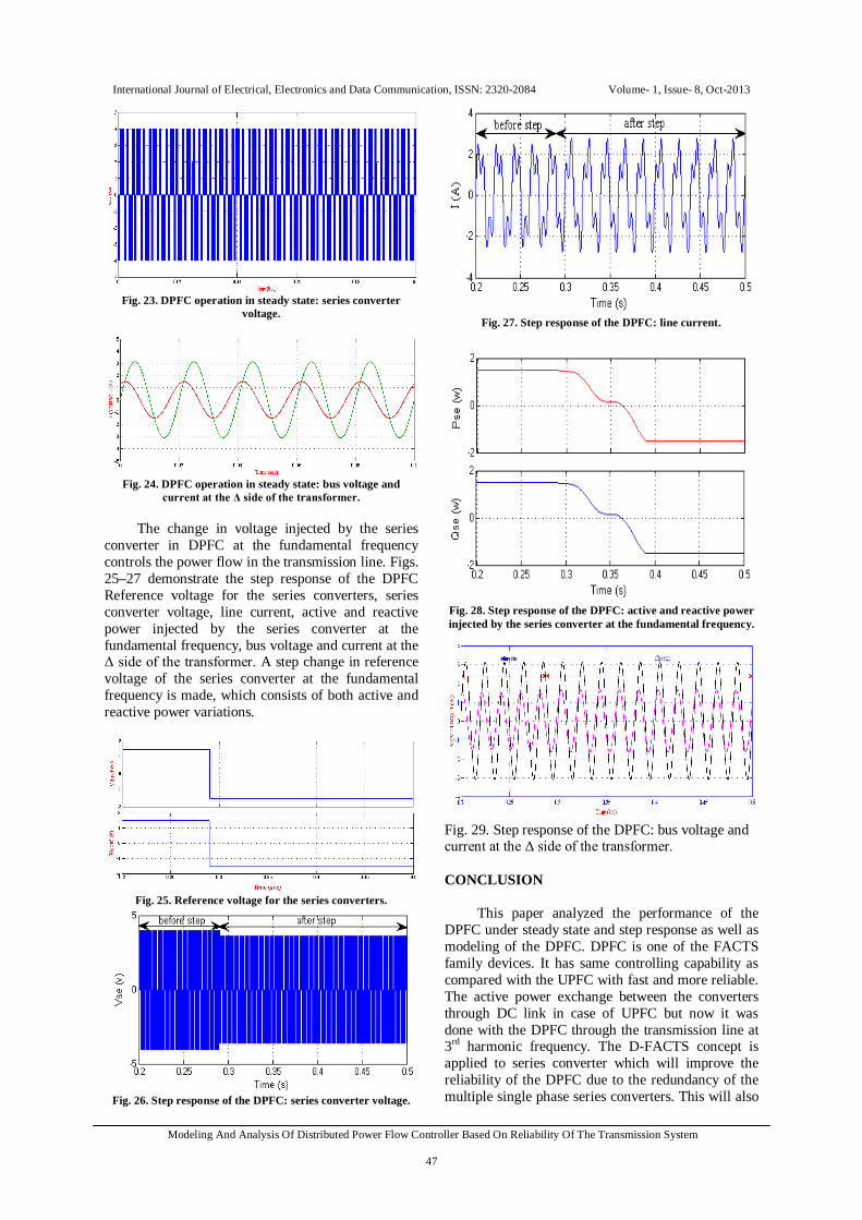
Fig. 23. DPFC operation in steady state: series converter
voltage.
Fig. 24. DPFC operation in steady state: bus voltage and
current at the Δ side of the transformer.
The change in voltage injected by the series converter in DPFC at the fundamental frequency controls the power flow in the transmission line. Figs. 25–27 demonstrate the step response of the DPFC Reference voltage for the series converters, series converter voltage, line current, active and reactive power injected by the series converter at the fundamental frequency, bus voltage and current at the Δ side of the transformer. A step change in reference voltage of the series converter at the fundamental frequency is made, which consists of both active and reactive power variations.
Fig. 25. Reference voltage for the series converters.
Fig. 26. Step response of the DPFC: series converter voltage.
Fig. 27. Step response of the DPFC: line current.
Fig. 28. Step response of the DPFC: active and reactive power injected by the series converter at the fundamental frequency.
Fig. 29. Step response of the DPFC: bus voltage and current at the Δ side of the transformer. CONCLUSION
This paper analyzed the performance of the DPFC under steady state and step response as well as modeling of the DPFC. DPFC is one of the FACTS family devices. It has same controlling capability as compared with the UPFC with fast and more reliable. The active power exchange between the converters through DC link in case of UPFC but now it was done with the DPFC through the transmission line at 3rd harmonic frequency. The D-FACTS concept is applied to series converter which will improve the reliability of the DPFC due to the redundancy of the multiple single phase series converters. This will also
International Journal of Electrical, Electronics and Data Communication, ISSN: 2320-2084 Volume- 1, Issue- 8, Oct-2013
Modeling And Analysis Of Distributed Power Flow Controller Based On Reliability Of The Transmission System
48
reduce the total cost of the DPFC because no high-voltage isolation is required at the series-converter component and the rating of the components of is low. The simulation model of the DPFC proved that the active power exchange between the shunt and series converters at the third-harmonic frequency and the series converters are able to inject controllable active and reactive power at the fundamental frequency. REFERENCES [1] Y.-H.Song and A. Johns, Flexible ac Transmission Systems
(FACTS) (IEE Power and Energy Series), vol. 30. London, U.K.: Institution of Electrical Engineers, 1999.
[2] L.Gyugyi, C.D.Schauder, S.L.Williams,T.R. Rietman,D. R. Torgerson, andA. Edris,“The unified power flow controller:Anewapproach to power transmission control,” IEEE Trans. Power Del., vol. 10, no. 2, pp. 1085–1097, Apr. 1995.
[3] L. Gyugyi. “Unified power-flow control concept for flexible C Transmission systems”. In: Generation, Transmission and Distribution, IEE Proceedings Conference on, 1992.
[4] L. Gyugyi, C. D. Schauder, S. L. Williams, T. R. Rietman, D. R. Torgerson, and A. Edris. “The unified power flow controller: a new approach to power transmission control”. Power Delivery, IEEE Transactions on, 1995.
[5] S. Kannan, S. Jayaram, and M. M. A. Salama. “Real and reactive power co-ordination for a unified power flow controller”. Power Systems, IEEE Transactions on, 2004.
[6] M. D. Deepak, E. B. William, S. S. Robert, K. Bill, W. G. Randal, T. B. Dale, R. I. Michael, and S. G. Ian, “A distributed static series compensator system for realizing active power flow control on existing power lines,” IEEE Trans. Power Del., vol. 22, no. 1, pp. 642–649, Jan. 2007.
[7] A. E. Fitzgerald, C. Kingsley, and S. D. Umans. Electric machinery. McGraw Hill, 2003.
[8] H. Soo-Bin, C. Gyu-Hyeong, J. Bong-Man, and C. Soo-Hyun. “Vector transformed circuit theory and application to converter modeling/analysis”. In: Power Electronics Specialists Conference, IEEE, 1998.
[9] Y. H. Song and A. Johns. Flexible ac transmission systems (FACTS). Institution of Electrical Engineers, 1999.