Embed Size (px)
Citation preview
14th World Congress in Mechanism and Machine Science, Taipei, Taiwan, 25-30 October, 2015 IMD-123
Modeling and Analysis of a Flexible End-effector for Actuating EndoscopicCatheters
K. P. Ashwin∗ Don. P Jose† Ashitava Ghosal‡
Indian Institute of ScienceBangalore, India
Abstract—Precise positioning of catheters during an en-doscopic procedure and surgery is typically a very complexand demanding task. Once endoscope tip is stationed ata particular position, the camera is focused at a particu-lar point. In most endoscopes, any motion of the catheteris achieved by moving the endoscope tip which results ina change in camera focus. This paper presents an inno-vative end-effector design which may be used alongside acamera in such a way that independent motion of catheteris achieved. The design utilizes the advantages of miniatur-ized pneumatic artificial muscles (MPAM) with a diameterless than 1.2 mm. Three such MPAMs are arranged in amanner so that the tip of the end-effector can be moved byover 15 mm in three-dimensions. This paper presents thedetailed design, characteristics of MPAM used, kinemat-ics of end-effector and hardware implementation used toachieve arbitrary tip motion of the end-effector.
Keywords: McKibben air muscle, miniaturized pneumatic actua-tors, minimally invasive surgical tools, soft robotics
I. Introduction
Endoscopy is a medical procedure in which a long tubecalled an endoscope is inserted inside a patient’s gastro-intestinal tract typically for diagnosis. Similar procedurescalled colonoscopy is used for examination of the colon. Inthese procedures, a standard flexible endoscope contains acamera, a fibre optic based illumination and image capturesystem, air-water channels and nozzle for removing obsta-cles all enclosed in a flexible tube of about 7 to 15 mm di-ameter. Almost all commercially available endoscopes alsocarry a channel through which an instrument (catheter) canbe introduced at the distal end. The instrument (catheter)can be operated by the doctor/technician from the dorsalend (holding end) of the endoscope. Depending on the dif-ferent types of catheters, endoscopy can also be used for ex-tracting tissue for biopsy, some forms of treatments as wellas surgery. However, in most commonly available endo-scopes, once a catheter is introduced at the distal end, the in-dependent motion of catheter from camera is not possible—the endoscopists are not able to move the catheter laterallywhile keeping the camera stationary.
∗[email protected]†[email protected]‡[email protected]
A few commercially available endoscope platforms usedfor natural orifice translumenal endoscopic surgery addressthis issue[1]. These are either very expensive and do notoften use the same standard catheters available in the mar-ket. Conventional actuation techniques are not quite suit-able in actuating endoscopic catheters since both precisecontrol and flexibility are desired at a miniature size. Atpresent, the tip of endoscope is moved by pulling a set ofstrings(tendons), as in [2], which actuates a series of uni-versal joints. This technique cannot be easily applied foractuating catheter since the load carrying capacity is verylow. Also, the end-effector in actuated position needs tobe compliant against external forces—like when endoscopepresses against the side walls of GI tract—so that chancesof endoscope tearing tissues (’perforation’) are minimized.The conventional tendon-driven mechanisms might not beable to exhibit required compliance in actuated position.The use of micro-motors is ruled out since it increases theweight at the tip of endoscope apart from making the endof the endoscope rigid. Shape memory alloy (SMA) wireshave the required flexibility and precise positioning capa-bility[3, 4, 5]. However, the response time of SMA wiresare large (of the order of tens of seconds) and in some in-stances the temperature increase due to heating of SMAwires for their actuation is not desirable. McKibben actua-tor/ Pneumatic Air Muscle(PAM), actuated by pressurizedfluid, are promising actuators due to two principal advan-tages: soft and highly flexible when not pressurized andstiff and large load carrying capacity when pressurized[6],[7]. A McKibben actuator/PAM consists of a hollow hype-elastic tube/bladder which is braided on the outside usinga mesh of inextensible cords. One end of the tube/bladderis sealed and compressed air is allowed to enter throughthe other end. The tube/bladder in its normal unpressur-ized state is soft and very flexible. Upon pressurizing, thetube/bladder inflates while the inextensible mesh on theouter surface limits the expansion to a particular volume. Itcan be shown that if the initial angle of winding of a cross-mesh (braiding) is less than 54.7◦, the air muscle will con-tract longitudinally and can carry axial load while it is pres-surized [6]. Pneumatic air muscles were first introduced in1950s, but very little use of these are found for precise po-sitioning. This is primarily due to the unavailability of sat-isfactory theoretical models and difficulty in control[8]. Inthis work, we use miniaturized PAM (MPAM) with diame-
1
14th World Congress in Mechanism and Machine Science, Taipei, Taiwan, 25-30 October, 2015 IMD-123
ter of 1.2 mm for development of a catheter which can beindependently positioned in a two-dimensional region [9].We present characterization of these MPAMs, a design of acatheter actuated by three MPAMs, and initial attempts atderiving the kinematics of an end-effector and its control.
The paper presents an innovative end-effector designwhich uses MPAM to actuate commercially available orspecially designed catheter for endoscopy. Section II detailsthe end-effector configuration and its design. In section III,MPAM used for moving the end-effector is analyzed for de-flection and force generated. In section IV, the kinematicsand workspace of end effector is studied for single air mus-cle actuation and when two air muscles are actuated simul-taneously. In section V, the hardware for real-time controlof the end-effector and its interfacing with a thumb stick in-put device is described. In section VI, representative exper-imental results are reported and the conclusions and scopefor future work are presented in section VII.
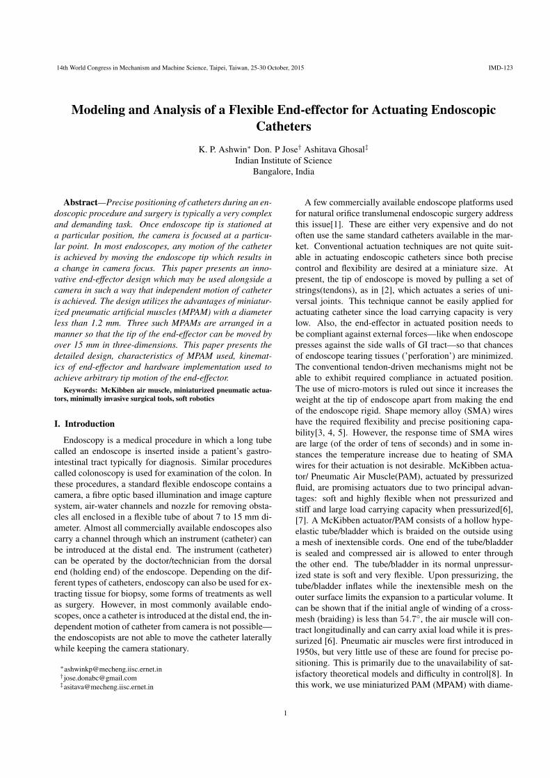
II. End-effector DesignA CAD model as well as the fabricated end-effector is
shown in Fig.1 and Fig.2 respectively. The end-effectorconsists of two holders on either ends, each having a centralhole of 3.5 mm diameter for catheter entry and three holesof 2 mm diameter, 120◦ apart for placement of MPAMs.The separation between dorsal and distal holders decidesthe overall length of end-effector and hence the length ofthe MPAM used. A minimum end-effector deflection of10 mm is desired for convenient positioning of the tip of acatheter and this is kept as a design target during the fabri-cation. It has been experimentally observed that air musclelength below 40 mm does not produce a large enough forceto bend standard forceps catheter to required deflection[9].In addition, since the depth of view of a typical endoscopiccamera is between 0 to 90mm, a 45 mm length of the airmuscles was chosen in the design.
Catheter
Outer spring
Inner spring
Air muscle
Distal holder
Dorsal holder
Teflon tube
Fig. 1. Components of end-effector and CAD model
As shown in Fig. 1, a wound coil of 4 mm outer diame-ter is fixed in the center. This coil serves two purposes—itacts as a passage for catheter without interfering with thepneumatic air muscles and also acts as a fulcrum on whichthe catheter will bend when air muscle is energized. Thecoil is pre-stressed to get high axial stiffness and minimal
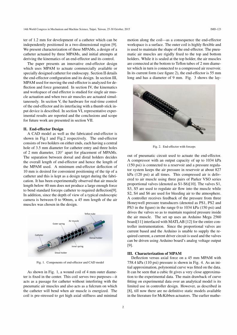
motion along the coil—as a consequence the end-effectorworkspace is a surface. The outer coil is highly flexible andis used to maintain the shape of the end-effector. The pneu-matic air muscles are rigidly fixed to the top and bottomholders. While it is sealed at the top holder, the air musclesare connected at the bottom to Teflon tubes of 2 mm diame-ter which in turn is connected to a compressed air reservoir.In its current form (see figure 2), the end-effector is 55 mmlong and has a diameter of 9 mm. Fig. 3 shows the lay-
Fig. 2. End-effector with forceps
out of pneumatic circuit used to actuate the end-effector.A compressor with an output capacity of up to 1034 kPa(150 psi) is connected to a reservoir and a pressure regula-tor system keeps the air pressure in reservoir at about 827kPa (120 psi) at all times. This compressed air is deliv-ered to air muscle using three pairs of Parker VSO seriesproportional valves (denoted as S1-S6)[10]. The valves S1,S3, S5 are used to regulate air flow into the muscle whileS2, S4 and S6 are used for bleeding air to the atmosphere.A controller receives feedback of the pressure from threeHoneywell pressure transducers (denoted as PS1, PS2 andPS3 in the figure) in the range 0 to 1034 kPa (150 psi) anddrives the valves so as to maintain required pressure insidethe air muscle. The set up uses an Arduino Mega 2560board[11] interfaced with MATLAB [12] for the entire con-troller instrumentation. Since the proportional valves arecurrent based and the Arduino is unable to supply the re-quired current, a current driver circuit is used and the valvescan be driven using Arduino board’s analog voltage output[9].
III. Characterization of MPAMDeflection versus axial force on a 45 mm MPAM with
758.4 kPa (110 psi) pressure is shown in Fig. 4. As an ini-tial approximation, polynomial curve was fitted on the data.It can be seen that a cubic fit gives a very close approxima-tion to the experimental data. The main drawback of curvefitting on experimental data over an analytical model is itslimited use in controller design. However, as described in[8], till now there are no definitive static models availablein the literature for McKibben actuators. The earlier mathe-
2
14th World Congress in Mechanism and Machine Science, Taipei, Taiwan, 25-30 October, 2015 IMD-123
Fig. 3. Layout of pneumatic circuitry
displacement (mm)
0 0.2 0.4 0.6 0.8 1 1.2 1.4 1.6 1.8 2
Axia
l fo
rce
(N
)
0
0.2
0.4
0.6
0.8
1
1.2
1.4Axial force vs displacement for 45 mm air muscle
758.4 kPa, cubic fit
758.4 kPa, experimental
Fig. 4. Cubic fit on experimental data
matical models by Schulte[13] and Chou-Hannaford[6] de-viate from experimental results by more than 20% for theMPAM under consideration. One possible reason for thediscrepancy could be the idealized assumption in their mod-els that cylindrical air muscle remains cylindrical even af-ter pressurizing—this is not true for the MPAM used. Inaddition, the material properties are not considered in theirmodel.
An attempt on modeling McKibben actuators as fiber re-inforced elastic membrane (as given in [14]) was conductedby Liu and Rahn[15]. In their work, the authors find an it-erative solution to the equilibrium equations
d (λ2n2)
dλ2= n1 (1)
n1 cosσ
λ2+ n2
d cosσ
dλ2=
PR
2C(2)
Subject to boundary conditions
λ(L) = 1 (3)
n2(0) =PRλ2(0)
4C+
F
4πCRλ2(0)(4)
σ(0) = 0 (5)
to obtain the deformed shape of a pressurized actuator. Inthe above equation, P is the pressure inside the tube, Ris the initial radius, C is Mooney-Rivlin constant, σ is theslope of meridian, λ1, λ2 are the stretch ratios in the axialand lateral direction, n1, n2 are the stress per unit length inaxial and lateral direction.
The iterative procedure considers an initial value of λ2(0)and proceeds towards finding pressure P and thereby thedeformed shape. In our case, P(0) is a known quantity whileλ2(0) remains unknown and hence, the procedure had tobe modified. The results obtained for a 45 mm long 1.74mm diameter MPAM with 620.5 kPa (90 psi) and 758.4kPa (110 psi) applied pressure is shown in Fig. 5. Thesolution from the iterative formulation is plotted alongsideexperimental results for comparison. It can be seen thatthe trend is similar, with a maximum error of 1.6 mm indeflection. It maybe mentioned that the iterative solutionprocedure carried out in MATLAB takes about 74 secondsto complete.
displacement (mm)
0 0.5 1 1.5 2 2.5
Axia
l fo
rce
(N
)
0
0.2
0.4
0.6
0.8
1
1.2Axial force vs displacement for 45 mm air muscle
620.5 kPa, theoretical
620.5 kPa experimental
758.4 kPa theoretical
758.4 kPa experimental
Fig. 5. Fiber elastic membrane model comparison
IV. Kinematics of end-effectorIn this section, we present initial attempts at deriving
the kinematics of the end-effector constructed using threeMPAMs. The relationship between the applied pressure anddeflection of the end-effector is obtained when a single ortwo MPAMs are pressurized. The workspace of the fabri-cated end-effector is also obtained.
A. Single air muscle actuationA single air muscle is pressurized to analyze the max-
imum displacement of end-effector without the catheter.Since the air muscle is offset from the end-effector axis by apre-fixed distance, the end effector tip is subjected to a mo-ment which results in bending. In reference[16], the authorsshow the displacement of elephant trunk robot actuated bypushing and pulling a set of cables placed on either side of aflexible ’backbone’. The length of the cables decide the ele-phant trunk robot’s final shape. The end-effector presented
3
14th World Congress in Mechanism and Machine Science, Taipei, Taiwan, 25-30 October, 2015 IMD-123
in this work is similar to the elephant trunk robot with airmuscle being analogous to the cables and the inner springacting like the backbone. However, it should be noted thatthere are only 3 air muscles in our case and the air musclescontract and become stiffer on application of pressure.
𝑠 = 0
𝑠 = 𝑙0
𝜑𝑏(𝑠)𝜑 𝑎𝑚(𝑠)
𝑎
𝑥
𝑦
𝑎𝑖𝑟 𝑚𝑢𝑠𝑐𝑙𝑒
𝑏𝑎𝑐𝑘𝑏𝑜𝑛𝑒
Fig. 6. Analogy with elephant trunk model
From reference[16], we get the expressions for shape ofbackbone and cables which are deflected in a 2-D plane.These are given as
ψb(s) =l0µ
(sin (µs)
1− cos (µs)
)(6)
ψam(s) =l0µ
(sin (µs)
1− cos (µs)
)+ a
(− sin (µs)cos (µs)
)(7)
where ψb(s) and ψam(s) represents the position vector ofbackbone and air muscle respectively, parameter s variesfrom 0 to l0 with l0 denoting the original length of the air
muscle, µ =δ
2awith δ as the displacement of the air mus-
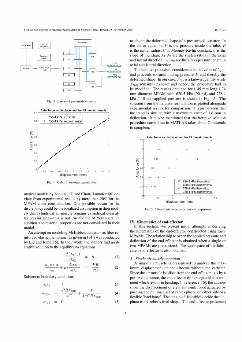
cle from initial length upon application of pressure, and a isthe fixed distance between air muscle and backbone. Fromthe above section, we find δ = 14.68 mm for a 45 mm longair muscle at 827 kPa (120 psi) pressure and a = 3mm. Fig.7 shows the predicted deflection (shown by red backboneand white air muscles) overlapped on actual deflection ofend effector. It can be seen that theoretical prediction agreesreasonably well with actual displacement.
The above model could not be used in the case of end-effector with catheter attached due to two possible reasons.• The coils used for end-effector fabrication has very lowtransverse stiffness and hence the reaction force experi-enced on air muscle is very small if catheter is not included.However, once catheter is introduced, the reaction forcesare not negligible and the value of forces vary with differ-ent catheters used.• When pressurized, the air muscles other than the oneactuated are compressed towards the coil by catheter and
Fig. 7. End effector bending at 827 kPa
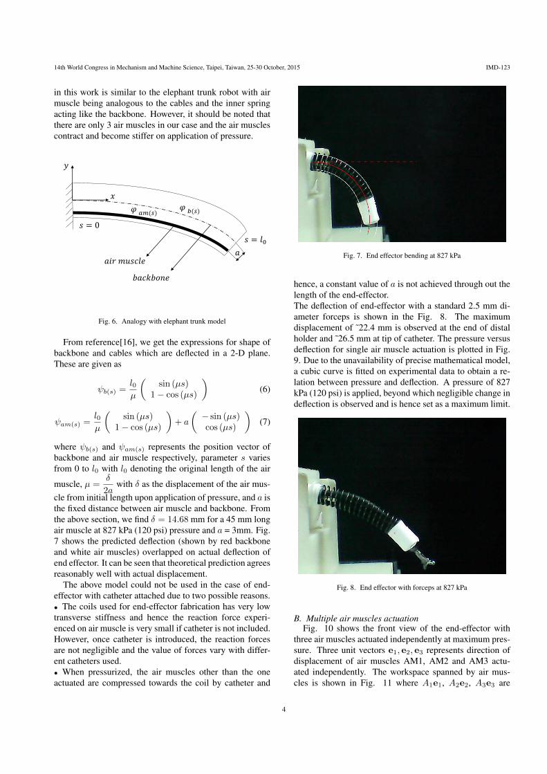
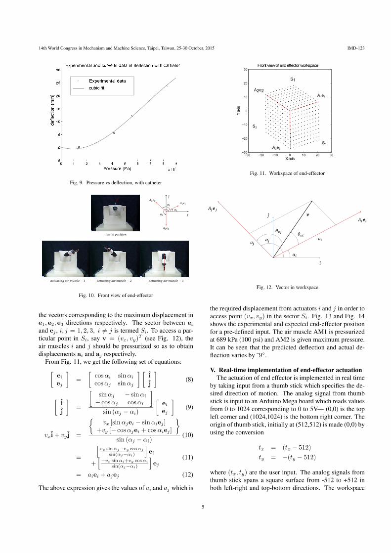
hence, a constant value of a is not achieved through out thelength of the end-effector.The deflection of end-effector with a standard 2.5 mm di-ameter forceps is shown in the Fig. 8. The maximumdisplacement of ˜22.4 mm is observed at the end of distalholder and ˜26.5 mm at tip of catheter. The pressure versusdeflection for single air muscle actuation is plotted in Fig.9. Due to the unavailability of precise mathematical model,a cubic curve is fitted on experimental data to obtain a re-lation between pressure and deflection. A pressure of 827kPa (120 psi) is applied, beyond which negligible change indeflection is observed and is hence set as a maximum limit.
Fig. 8. End effector with forceps at 827 kPa
B. Multiple air muscles actuationFig. 10 shows the front view of the end-effector with
three air muscles actuated independently at maximum pres-sure. Three unit vectors e1, e2, e3 represents direction ofdisplacement of air muscles AM1, AM2 and AM3 actu-ated independently. The workspace spanned by air mus-cles is shown in Fig. 11 where A1e1, A2e2, A3e3 are
4
14th World Congress in Mechanism and Machine Science, Taipei, Taiwan, 25-30 October, 2015 IMD-123
0 1 2 3 4 5 6 7 8 9
x 105
−5
0
5
10
15
20
25
30
Fig. 9. Pressure vs deflection, with catheter
𝑖𝑛𝑖𝑡𝑖𝑎𝑙 𝑝𝑜𝑠𝑖𝑡𝑖𝑜𝑛
𝑎𝑐𝑡𝑢𝑎𝑡𝑖𝑛𝑔 𝑎𝑖𝑟 𝑚𝑢𝑠𝑐𝑙𝑒 − 1 𝑎𝑐𝑡𝑢𝑎𝑡𝑖𝑛𝑔 𝑎𝑖𝑟 𝑚𝑢𝑠𝑐𝑙𝑒 − 2 𝑎𝑐𝑡𝑢𝑎𝑡𝑖𝑛𝑔 𝑎𝑖𝑟 𝑚𝑢𝑠𝑐𝑙𝑒 − 3
𝐴1𝑒1𝐴2𝑒2
𝐴3𝑒3
𝑖
𝑗
𝑖
𝑗
𝛼1
𝛼2
𝛼3
Fig. 10. Front view of end-effector
the vectors corresponding to the maximum displacement ine1, e2, e3 directions respectively. The sector between eiand ej , i, j = 1, 2, 3, i 6= j is termed Si. To access a par-ticular point in Si, say v = (vx, vy)
T (see Fig. 12), theair muscles i and j should be pressurized so as to obtaindisplacements ai and aj respectively.
From Fig. 11, we get the following set of equations:[eiej
]=
[cosαi sinαicosαj sinαj
] [i
j
](8)
[i
j
]=
[sinαj − sinαi− cosαj cosαi
]sin (αj − αi)
[eiej
](9)
vxi+ vy j =
{vx [sinαjei − sinαiej ]
+vy [− cosαjei + cosαiej ]
}sin (αj − αi)
(10)
=
[vx sinαj−vy cosαj
sin(αj−αi)
]ei
+[−vx sinαi+vy cosαi
sin(αj−αi)
]ej
(11)
= aiei + ajej (12)
The above expression gives the values of ai and aj which is
−30 −20 −10 0 10 20 30−30
−20
−10
0
10
20
30
X axis
Y a
xis
Front view of end effector workspace
A2e2A1e1
A3e3
S1
S3
S2
Fig. 11. Workspace of end-effector
𝐴𝑖𝒆𝑖
𝐴𝑗𝒆𝑗
𝑖
𝑗
𝑎𝑖𝑎𝑗
𝒗
𝛼𝑖
𝛼𝑗
𝜃𝑣𝑖𝜃𝑣𝑗
Fig. 12. Vector in workspace
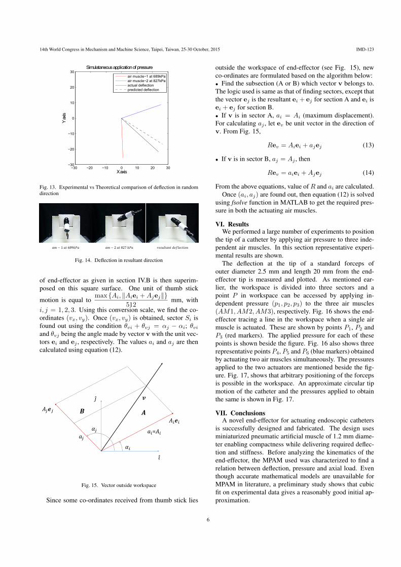
the required displacement from actuators i and j in order toaccess point (vx, vy) in the sector Si. Fig. 13 and Fig. 14shows the experimental and expected end-effector positionfor a pre-defined input. The air muscle AM1 is pressurizedat 689 kPa (100 psi) and AM2 is given maximum pressure.It can be seen that the predicted deflection and actual de-flection varies by ˜9◦.
V. Real-time implementation of end-effector actuationThe actuation of end effector is implemented in real time
by taking input from a thumb stick which specifies the de-sired direction of motion. The analog signal from thumbstick is input to an Arduino Mega board which reads valuesfrom 0 to 1024 corresponding to 0 to 5V— (0,0) is the topleft corner and (1024,1024) is the bottom right corner. Theorigin of thumb stick, initially at (512,512) is made (0,0) byusing the conversion
tx = (tx − 512)
ty = −(ty − 512)
where (tx, ty) are the user input. The analog signals fromthumb stick spans a square surface from -512 to +512 inboth left-right and top-bottom directions. The workspace
5
14th World Congress in Mechanism and Machine Science, Taipei, Taiwan, 25-30 October, 2015 IMD-123
−30 −20 −10 0 10 20 30−30
−20
−10
0
10
20
30
X axis
Y a
xis
Simulataneous application of pressure
air muscle−1 at 689kPa
air muscle−2 at 827kPa
actual deflection
predicted deflection
Fig. 13. Experimental vs Theoretical comparison of deflection in randomdirection
𝑎𝑚 − 1 𝑎𝑡 689𝑘𝑃𝑎 𝑎𝑚 − 2 𝑎𝑡 827 𝑘𝑃𝑎 𝑟𝑒𝑠𝑢𝑙𝑡𝑎𝑛𝑡 𝑑𝑒𝑓𝑙𝑒𝑐𝑡𝑖𝑜𝑛
Fig. 14. Deflection in resultant direction
of end-effector as given in section IV.B is then superim-posed on this square surface. One unit of thumb stick
motion is equal tomax {Ai, ‖Aiei +Ajej‖}
512mm, with
i, j = 1, 2, 3. Using this conversion scale, we find the co-ordinates (vx, vy). Once (vx, vy) is obtained, sector Si isfound out using the condition θvi + θvj = αj − αi; θviand θvj being the angle made by vector v with the unit vec-tors ei and ej , respectively. The values ai and aj are thencalculated using equation (12).
𝐴𝑖𝒆𝑖
𝐴𝑗𝒆𝑗
𝑖
𝑗
𝑎𝑖=𝐴𝑖𝑎𝑗
𝒗
𝛼𝑖
𝛼𝑗
𝑨𝑩
Fig. 15. Vector outside workspace
Since some co-ordinates received from thumb stick lies
outside the workspace of end-effector (see Fig. 15), newco-ordinates are formulated based on the algorithm below:• Find the subsection (A or B) which vector v belongs to.The logic used is same as that of finding sectors, except thatthe vector ej is the resultant ei + ej for section A and ei isei + ej for section B.• If v is in sector A, ai = Ai (maximum displacement).For calculating aj , let ev be unit vector in the direction ofv. From Fig. 15,
Rev = Aiei + ajej (13)
• If v is in sector B, aj = Aj , then
Rev = aiei +Ajej (14)
From the above equations, value ofR and ai are calculated.Once (ai, aj) are found out, then equation (12) is solved
using fsolve function in MATLAB to get the required pres-sure in both the actuating air muscles.
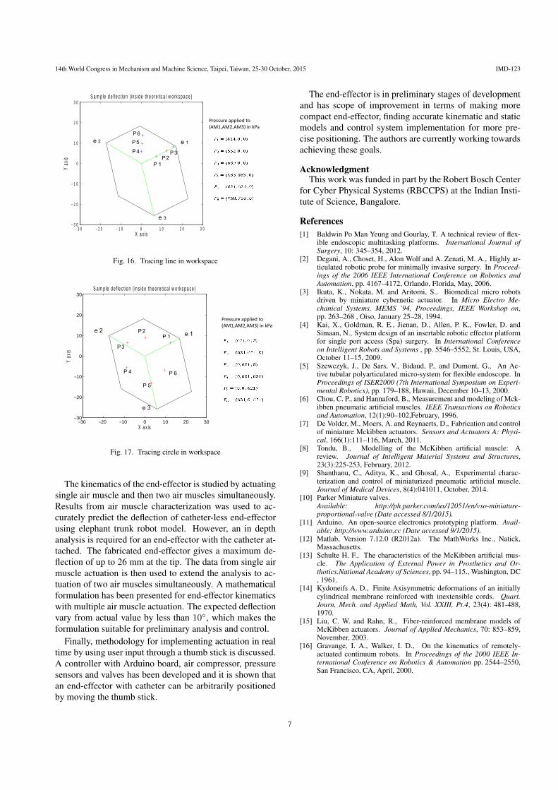
VI. ResultsWe performed a large number of experiments to position
the tip of a catheter by applying air pressure to three inde-pendent air muscles. In this section representative experi-mental results are shown.
The deflection at the tip of a standard forceps ofouter diameter 2.5 mm and length 20 mm from the end-effector tip is measured and plotted. As mentioned ear-lier, the workspace is divided into three sectors and apoint P in workspace can be accessed by applying in-dependent pressure (p1, p2, p3) to the three air muscles(AM1, AM2, AM3), respectively. Fig. 16 shows the end-effector tracing a line in the workspace when a single airmuscle is actuated. These are shown by points P1, P2 andP3 (red markers). The applied pressure for each of thesepoints is shown beside the figure. Fig. 16 also shows threerepresentative points P4, P5 and P6 (blue markers) obtainedby actuating two air muscles simultaneously. The pressuresapplied to the two actuators are mentioned beside the fig-ure. Fig. 17, shows that arbitrary positioning of the forcepsis possible in the workspace. An approximate circular tipmotion of the catheter and the pressures applied to obtainthe same is shown in Fig. 17.
VII. ConclusionsA novel end-effector for actuating endoscopic catheters
is successfully designed and fabricated. The design usesminiaturized pneumatic artificial muscle of 1.2 mm diame-ter enabling compactness while delivering required deflec-tion and stiffness. Before analyzing the kinematics of theend-effector, the MPAM used was characterized to find arelation between deflection, pressure and axial load. Eventhough accurate mathematical models are unavailable forMPAM in literature, a preliminary study shows that cubicfit on experimental data gives a reasonably good initial ap-proximation.
6
14th World Congress in Mechanism and Machine Science, Taipei, Taiwan, 25-30 October, 2015 IMD-123
3 0− 2 0− 1 0− 0 1 0 2 0 3 03 0−
2 0−
1 0−
0
1 0
2 0
3 0
X a x is
Y ax
is
S a m p le d e fle c t io n ( in s id e th e o re t ic a l w o rk s p a c e )
e 2 e 1
e 3
P 4
P 5
P 6
P 1P 2
P 3
Pressure applied to(AM1,AM2,AM3) in kPa
Fig. 16. Tracing line in workspace
30− 20− 10− 0 10 20 3030−
20−
10−
0
10
20
30
X a x is
Y ax
is
S a m p le d e f le c t io n ( in s id e th e o re tic a l w o rk s p a c e )
e 1e 2
e 3
P 1P 2
P 3
P 4
P 5
P 6
Pressure applied to(AM1,AM2,AM3) in kPa
Fig. 17. Tracing circle in workspace
The kinematics of the end-effector is studied by actuatingsingle air muscle and then two air muscles simultaneously.Results from air muscle characterization was used to ac-curately predict the deflection of catheter-less end-effectorusing elephant trunk robot model. However, an in depthanalysis is required for an end-effector with the catheter at-tached. The fabricated end-effector gives a maximum de-flection of up to 26 mm at the tip. The data from single airmuscle actuation is then used to extend the analysis to ac-tuation of two air muscles simultaneously. A mathematicalformulation has been presented for end-effector kinematicswith multiple air muscle actuation. The expected deflectionvary from actual value by less than 10◦, which makes theformulation suitable for preliminary analysis and control.
Finally, methodology for implementing actuation in realtime by using user input through a thumb stick is discussed.A controller with Arduino board, air compressor, pressuresensors and valves has been developed and it is shown thatan end-effector with catheter can be arbitrarily positionedby moving the thumb stick.
The end-effector is in preliminary stages of developmentand has scope of improvement in terms of making morecompact end-effector, finding accurate kinematic and staticmodels and control system implementation for more pre-cise positioning. The authors are currently working towardsachieving these goals.
AcknowledgmentThis work was funded in part by the Robert Bosch Center
for Cyber Physical Systems (RBCCPS) at the Indian Insti-tute of Science, Bangalore.
References[1] Baldwin Po Man Yeung and Gourlay, T. A technical review of flex-
ible endoscopic multitasking platforms. International Journal ofSurgery, 10: 345–354, 2012.
[2] Degani, A., Choset, H., Alon Wolf and A. Zenati, M. A., Highly ar-ticulated robotic probe for minimally invasive surgery. In Proceed-ings of the 2006 IEEE International Conference on Robotics andAutomation, pp. 4167–4172, Orlando, Florida, May, 2006.
[3] Ikuta, K., Nokata, M. and Aritomi, S., Biomedical micro robotsdriven by miniature cybernetic actuator. In Micro Electro Me-chanical Systems, MEMS ’94, Proceedings, IEEE Workshop on,pp. 263–268 , Oiso, January 25–28, 1994.
[4] Kai, X., Goldman, R. E., Jienan, D., Allen, P. K., Fowler, D. andSimaan, N., System design of an insertable robotic effector platformfor single port access (Spa) surgery. In International Conferenceon Intelligent Robots and Systems , pp. 5546–5552, St. Louis, USA,October 11–15, 2009.
[5] Szewczyk, J., De Sars, V., Bidaud, P., and Dumont, G., An Ac-tive tubular polyarticulated micro-system for flexible endoscope. InProceedings of ISER2000 (7th International Symposium on Experi-mental Robotics), pp. 179–188, Hawaii, December 10–13, 2000.
[6] Chou, C. P., and Hannaford, B., Measurement and modeling of Mck-ibben pneumatic artificial muscles. IEEE Transactions on Roboticsand Automation, 12(1):90–102,February, 1996.
[7] De Volder, M., Moers, A. and Reynaerts, D., Fabrication and controlof miniature Mckibben actuators. Sensors and Actuators A: Physi-cal, 166(1):111–116, March, 2011.
[8] Tondu, B., Modelling of the McKibben artificial muscle: Areview. Journal of Intelligent Material Systems and Structures,23(3):225-253, February, 2012.
[9] Shanthanu, C., Aditya, K., and Ghosal, A., Experimental charac-terization and control of miniaturized pneumatic artificial muscle.Journal of Medical Devices, 8(4):041011, October, 2014.
[10] Parker Miniature valves.Available: http://ph.parker.com/us/12051/en/vso-miniature-proportional-valve (Date accessed 8/1/2015).
[11] Arduino. An open-source electronics prototyping platform. Avail-able: http://www.arduino.cc (Date accessed 9/1/2015).
[12] Matlab, Version 7.12.0 (R2012a). The MathWorks Inc., Natick,Massachusetts.
[13] Schulte H. F., The characteristics of the McKibben artificial mus-cle. The Application of External Power in Prosthetics and Or-thotics.National Academy of Sciences, pp. 94–115., Washington, DC, 1961.
[14] Kydoneifs A. D., Finite Axisymmetric deformations of an initiallycylindrical membrane reinforced with inextensible cords. Quart.Journ, Mech. and Applied Math, Vol. XXIII, Pt.4, 23(4): 481-488,1970.
[15] Liu, C. W. and Rahn, R., Fiber-reinforced membrane models ofMcKibben actuators. Journal of Applied Mechanics, 70: 853–859,November, 2003.
[16] Gravange, I. A., Walker, I. D., On the kinematics of remotely-actuated continuum robots. In Proceedings of the 2000 IEEE In-ternational Conference on Robotics & Automation pp. 2544–2550,San Francisco, CA, April, 2000.
7