Embed Size (px)
Citation preview
PATRAN 322 Exercise Workbook 6-1
LESSON 6
Modeling a Shell to a Solid Elements Transition
Objectives:
■ Use MPCs to replicate a Solid with a Surface
■ Compare stress results of the Solid and Surface

6-2 PATRAN 322 Exercise Workbook
LESSON 6 Modeling a Shell to a Solid Element
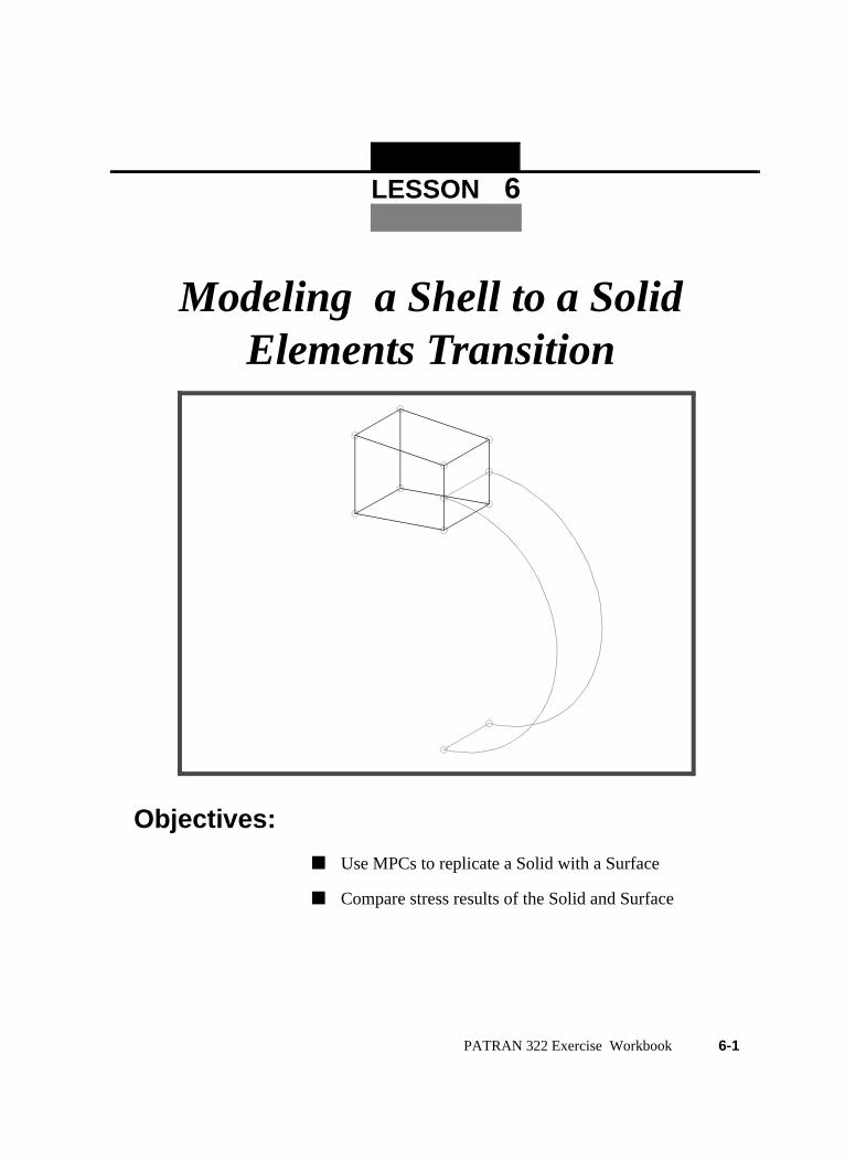
Model Description:In this exercise, you will create a solid/surface transition. Though theuse of a thickness field and MPCs the surface will represent acontinuation of the solid.
The Model appears below
PATRAN 322 Exercise Workbook 6-3
Exercise Procedure:
1. Open a new database. Name it shell_solid
The viewport (PATRAN’s graphics window) will appear along with aNew Model Preference form. The New Model Preference sets allthe code specific forms and options inside MSC/PATRAN.
2. In the New Model Preference form pick the followingoptions
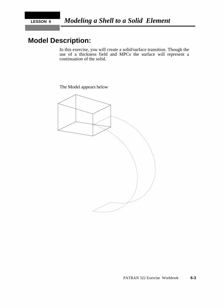
3. To create necessary geometry for the solid.
Start with the two surfaces that will define the solid
Increase the Point Size in order to see the points more clearly andchange the view to Isoview 3
File/New ...
New Database Name: shell_solid
OK
Analysis Code: MSC/ADVANCED_FEA
Analysis Type: Structural
OK
◆ Geometry
Action: Create
Object: Surface
Method: XYZ
Vector Coordinate List <40, 30, 3>
Origin Coordinate List [-40, 0, 34.93]
Apply
Action: Create
Object: Surface
6-4 PATRAN 322 Exercise Workbook
LESSON 6 Modeling a Shell to a Solid Element
Now create the solid
4. Delete the original surfaces
5. Create two points that will define the surface later
Method: XYZ
Vector Coordinate List <40, 30, -3>
Origin Coordinate List [-40, 0, 66.93]
Apply
Action: Create
Object: Solid
Method: Surface
Starting Surface List Surface 1
Ending Surface List Surface 2
Apply
Action: Delete
Object: Surface
Surface List: Surface 1 2
Apply
Action: Create
Object: Point
Method: Interpolate
Starting Point List Point 4 (see fig -1)
Ending Point List Point 8
Apply
PATRAN 322 Exercise Workbook 6-5
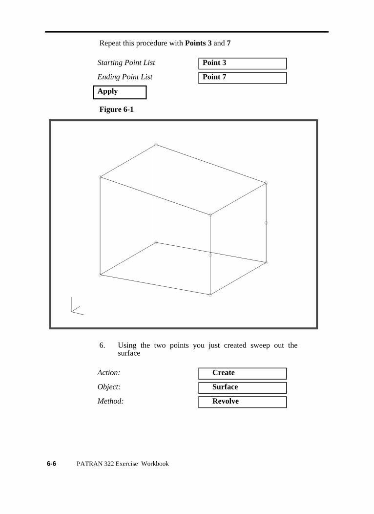
Repeat this procedure with Points 3 and 7
Figure 6-1
6. Using the two points you just created sweep out thesurface
Starting Point List Point 3
Ending Point List Point 7
Apply
Action: Create
Object: Surface
Method: Revolve
X
Y
Z
X
Y
Z
6-6 PATRAN 322 Exercise Workbook
LESSON 6 Modeling a Shell to a Solid Element
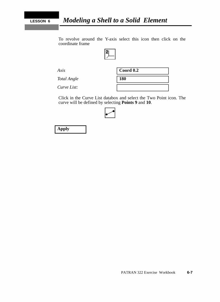
To revolve around the Y-axis select this icon then click on thecoordinate frame
Click in the Curve List databox and select the Two Point icon. Thecurve will be defined by selecting Points 9 and 10.
Axis Coord 0.2
Total Angle 180
Curve List:
Apply
PATRAN 322 Exercise Workbook 6-7
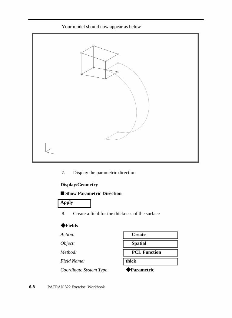
Your model should now appear as below
7. Display the parametric direction
8. Create a field for the thickness of the surface
Display/Geometry
■ Show Parametric Direction
Apply
◆ Fields
Action: Create
Object: Spatial
Method: PCL Function
Field Name: thick
Coordinate System Type ◆ Parametric
X
Y
Z
X
Y
Z
6-8 PATRAN 322 Exercise Workbook
LESSON 6 Modeling a Shell to a Solid Element
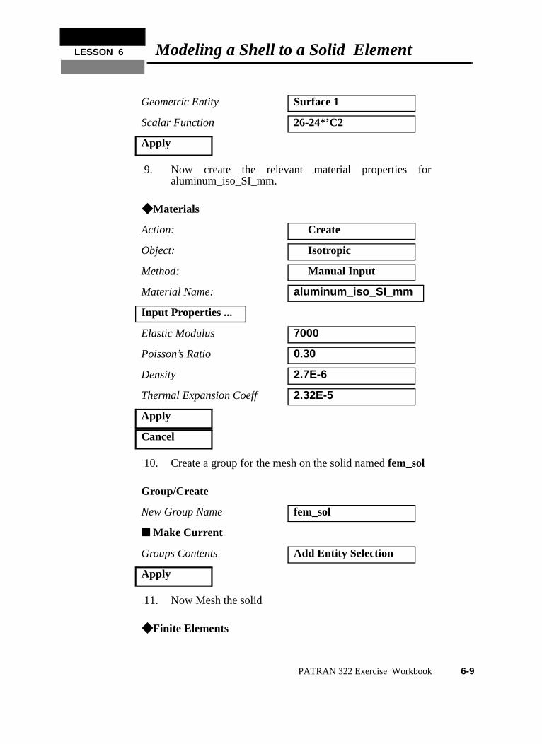
9. Now create the relevant material properties foraluminum_iso_SI_mm.
10. Create a group for the mesh on the solid named fem_sol
11. Now Mesh the solid
Geometric Entity Surface 1
Scalar Function 26-24*’C2
Apply
◆ Materials
Action: Create
Object: Isotropic
Method: Manual Input
Material Name: aluminum_iso_SI_mm
Input Properties ...
Elastic Modulus 7000
Poisson’s Ratio 0.30
Density 2.7E-6
Thermal Expansion Coeff 2.32E-5
Apply
Cancel
Group/Create
New Group Name fem_sol
■ Make Current
Groups Contents Add Entity Selection
Apply
◆ Finite Elements
PATRAN 322 Exercise Workbook 6-9
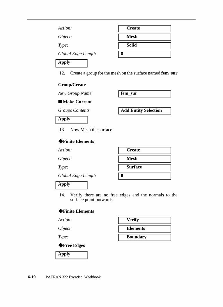
12. Create a group for the mesh on the surface named fem_sur
13. Now Mesh the surface
14. Verify there are no free edges and the normals to thesurface point outwards
Action: Create
Object: Mesh
Type: Solid
Global Edge Length 8
Apply
Group/Create
New Group Name fem_sur
■ Make Current
Groups Contents Add Entity Selection
Apply
◆ Finite Elements
Action: Create
Object: Mesh
Type: Surface
Global Edge Length 8
Apply
◆ Finite Elements
Action: Verify
Object: Elements
Type: Boundary
◆ Free Edges
Apply
6-10 PATRAN 322 Exercise Workbook
LESSON 6 Modeling a Shell to a Solid Element
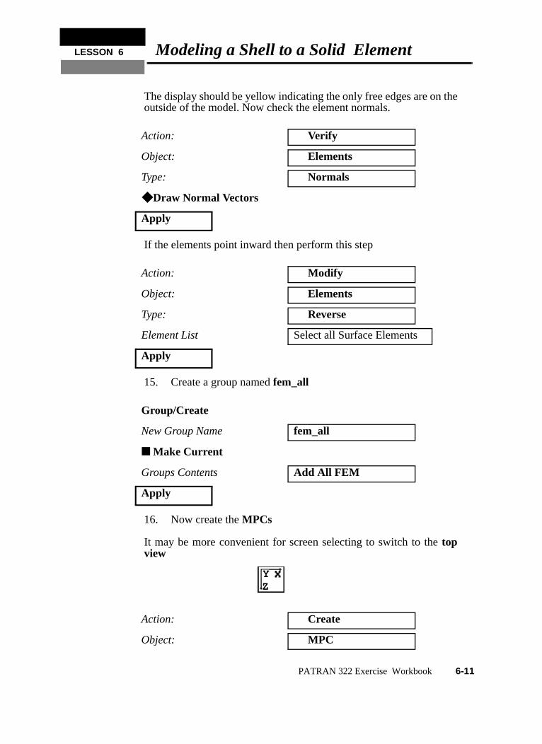
The display should be yellow indicating the only free edges are on theoutside of the model. Now check the element normals.
If the elements point inward then perform this step
15. Create a group named fem_all
16. Now create the MPCs
It may be more convenient for screen selecting to switch to the topview
Action: Verify
Object: Elements
Type: Normals
◆ Draw Normal Vectors
Apply
Action: Modify
Object: Elements
Type: Reverse
Element List Select all Surface Elements
Apply
Group/Create
New Group Name fem_all
■ Make Current
Groups Contents Add All FEM
Apply
Action: Create
Object: MPC
ZY
PATRAN 322 Exercise Workbook 6-11
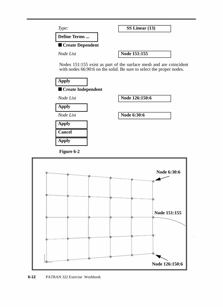
Nodes 151:155 exist as part of the surface mesh and are coincidentwith nodes 66:90:6 on the solid. Be sure to select the proper nodes.
Figure 6-2
Type: SS Linear (13)
Define Terms ...
■ Create Dependent
Node List Node 151:155
Apply
■ Create Independent
Node List Node 126:150:6
Apply
Node List Node 6:30:6
Apply
Cancel
Apply
XY
Z
XY
Z
Node 6:30:6
Node 126:150:6
Node 151:155
6-12 PATRAN 322 Exercise Workbook
LESSON 6 Modeling a Shell to a Solid Element
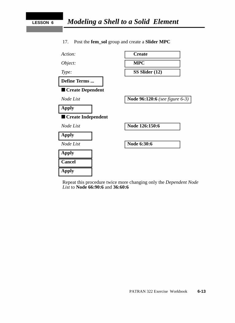
17. Post the fem_sol group and create a Slider MPC
Repeat this procedure twice more changing only the Dependent NodeList to Node 66:90:6 and 36:60:6
Action: Create
Object: MPC
Type: SS Slider (12)
Define Terms ...
■ Create Dependent
Node List Node 96:120:6 (see figure 6-3)
Apply
■ Create Independent
Node List Node 126:150:6
Apply
Node List Node 6:30:6
Apply
Cancel
Apply
PATRAN 322 Exercise Workbook 6-13
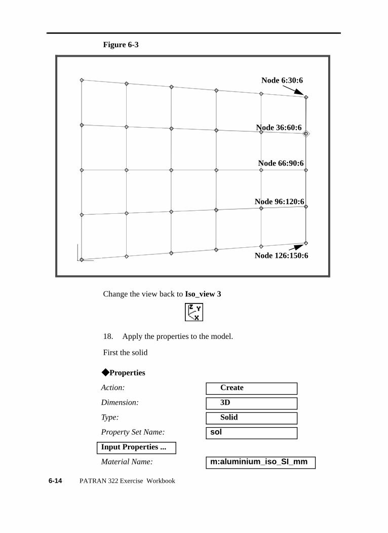
Figure 6-3
Change the view back to Iso_view 3
18. Apply the properties to the model.
First the solid
◆ Properties
Action: Create
Dimension: 3D
Type: Solid
Property Set Name: sol
Input Properties ...
Material Name: m:aluminium_iso_SI_mm
XY
Z
XY
Z
Node 96:120:6
Node 6:30:6
Node 126:150:6
Node 36:60:6
Node 66:90:6
6-14 PATRAN 322 Exercise Workbook
LESSON 6 Modeling a Shell to a Solid Element
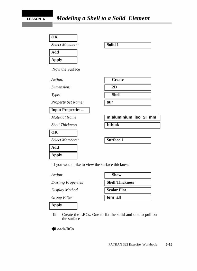
Now the Surface
If you would like to view the surface thickness
19. Create the LBCs. One to fix the solid and one to pull onthe surface
OK
Select Members: Solid 1
Add
Apply
Action: Create
Dimension: 2D
Type: Shell
Property Set Name: sur
Input Properties ...
Material Name m:aluminium_iso_SI_mm
Shell Thickness f:thick
OK
Select Members: Surface 1
Add
Apply
Action: Show
Existing Properties Shell Thickness
Display Method Scalar Plot
Group Filter fem_all
Apply
◆Loads/BCs
PATRAN 322 Exercise Workbook 6-15
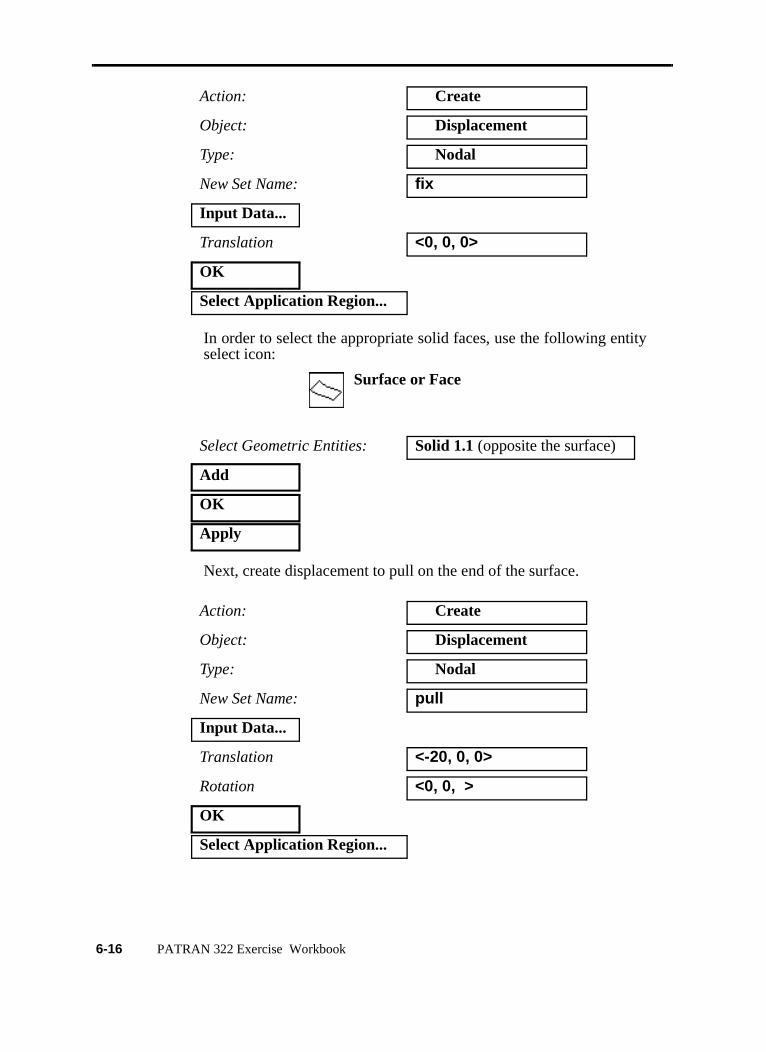
In order to select the appropriate solid faces, use the following entityselect icon:
Next, create displacement to pull on the end of the surface.
Action: Create
Object: Displacement
Type: Nodal
New Set Name: fix
Input Data...
Translation <0, 0, 0>
OK
Select Application Region...
Select Geometric Entities: Solid 1.1 (opposite the surface)
Add
OK
Apply
Action: Create
Object: Displacement
Type: Nodal
New Set Name: pull
Input Data...
Translation <-20, 0, 0>
Rotation <0, 0, >
OK
Select Application Region...
Surface or Face
6-16 PATRAN 322 Exercise Workbook
LESSON 6 Modeling a Shell to a Solid Element
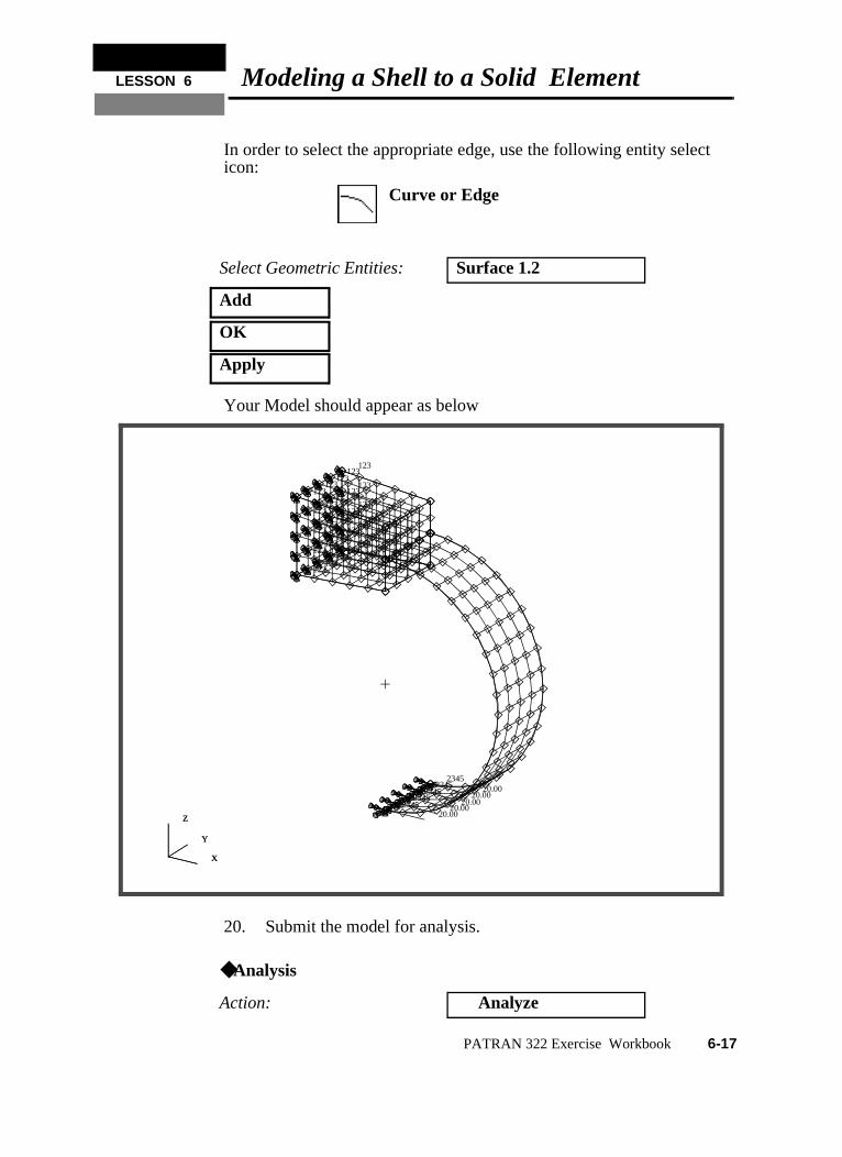
In order to select the appropriate edge, use the following entity selecticon:
Your Model should appear as below
20. Submit the model for analysis.
Select Geometric Entities: Surface 1.2
Add
OK
Apply
◆Analysis
Action: Analyze
Curve or Edge
X
Y
Z
123 123
123 123
123 123
123 123
123 123
123 123
123 123
123 123
123 123
123 123
123 123
123 123
123
234520.00
234520.00
234520.00
234520.00
234520.00
X
Y
Z
PATRAN 322 Exercise Workbook 6-17
You can monitor the progression of the job by looking at pull1.msgand pull1.sta files using the UNIX command tail -lf [filename]. Youcan also monitor the analysis in the background using the UNIXcommand ps -a.
21. Once the analysis is complete read the results back into thedatabase
22. Create a fringe plot of the stresses for the model
Object: Entire Model
Method: Full Run
Job Name: pull
Step Creation...
Job Step Name: pull1
Solution Type Nonlinear Static
Apply
Cancel
Step Selection...
Selected Job Steps: pull1
Apply
Apply
◆Analysis
Action: Read Results
Object: Results Entities
Method: Translate
Select Results File ...
Available Files: pull1.fil
OK
Apply
◆Results
Action: Create
6-18 PATRAN 322 Exercise Workbook
LESSON 6 Modeling a Shell to a Solid Element
Before viewing the stresses change the Deformation Attributes
Now switch back to the Select Results form
Notice that no stresses appear on the surface. This is because theresults for shell elements have layers and cannot be displayed on asingle surface. Create a new viewport so stresses on the solid and thesurface can be displayed at the same time.
Object: Quick Plot
Render Style Free Edge
Scale Interpretation ◆ True Scale
Scale Factor 1.0
❐ Show Undeformed
Select Results Case: Step1, Total Time=1
Select Fringe Results: Stress, Components
Position...((NON-LAYERED))
Quantity: Von Mises
Selected Deformation Results: Deformation, Displacement
Apply
Viewport/Create
New Viewport Name another
Apply
Cancel
PATRAN 322 Exercise Workbook 6-19
To see them side by side select:
To make the new viewport active click on the edge until the borderappears. Now post the default and fem_all groups in that viewport.
Now create a fringe plot of the surface in another viewport.Remember the surface has 5 different layers numbered 1 to 5, thebottom being the lowest number. Lets start with the middle layer.
Viewport/Tile
Group/Post
Select Groups to Post default_groupfem_all
Apply
Cancel
Select Results Case: Step1, Total Time=1
Select Fringe Results: Stress, Components
Position...((At SECTION_POINT_3))
Option: Average
Close
Quantity: Von Mises
Selected Deformation Results: Deformation, Displacement
Apply
6-20 PATRAN 322 Exercise Workbook
LESSON 6 Modeling a Shell to a Solid Element
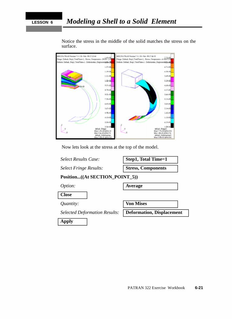
Notice the stress in the middle of the solid matches the stress on thesurface.
Now lets look at the stress at the top of the model.
Select Results Case: Step1, Total Time=1
Select Fringe Results: Stress, Components
Position...((At SECTION_POINT_5))
Option: Average
Close
Quantity: Von Mises
Selected Deformation Results: Deformation, Displacement
Apply
PATRAN 322 Exercise Workbook 6-21
p
s
te
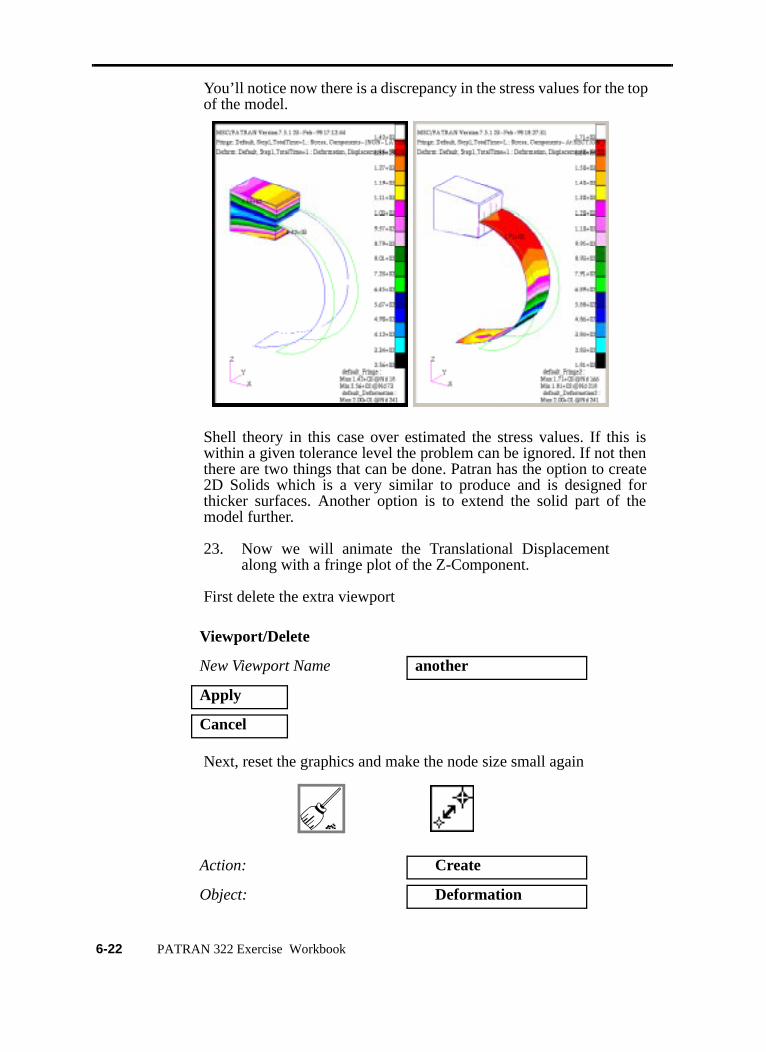
You’ll notice now there is a discrepancy in the stress values for the toof the model.
Shell theory in this case over estimated the stress values. If this iwithin a given tolerance level the problem can be ignored. If not thenthere are two things that can be done. Patran has the option to crea2D Solids which is a very similar to produce and is designed forthicker surfaces. Another option is to extend the solid part of themodel further.
23. Now we will animate the Translational Displacementalong with a fringe plot of the Z-Component.
First delete the extra viewport
Next, reset the graphics and make the node size small again
Viewport/Delete
New Viewport Name another
Apply
Cancel
Action: Create
Object: Deformation
6-22 PATRAN 322 Exercise Workbook
LESSON 6 Modeling a Shell to a Solid Element
Before hitting Apply select the Animation Options icon
Once the animation is set up pause it and create a second fringeanimation.
Again select the Animation Options icon
Select Results Case select all
Select Deformation Result Defomation, Displacement
■ Animate
Animation Method Global Variable
Select Global Variable Time
Animation Graphics 3D
Number of Frames 12
Apply
Action: Create
Object: Fringe
Select Results Case select all
Select Deformation Result Stress, Component
Quantity: Z Component
■ Animate
Animation Method Global Variable
Select Global Variable Time
Animation Graphics 3D
Number of Frames 12
PATRAN 322 Exercise Workbook 6-23
The two animations will appear together
You can play with different aspects of the animation, for example,pause the animation and select the Display Attributes icon
Another feature on the Animation Control form is Cycle and Bounce.Change it to Bounce.
This ends the exercise, you may quit Patran.
Apply
Style continuous
Apply
6-24 PATRAN 322 Exercise Workbook
![Assumed Natural Strain NURBS-based solid-shell element for ... · Assumed Natural Strain NURBS-based solid-shell element for the ... Benson and co-workers [22] proposed a quadratic](https://img.pdfslide.us/doc/110x75/5c0a2eac09d3f23c1a8b681c/assumed-natural-strain-nurbs-based-solid-shell-element-for-assumed-natural.jpg)