Embed Size (px)
Citation preview
Modeling a Deck Plate Girder Bridge
By Charlie Crawford, MMR
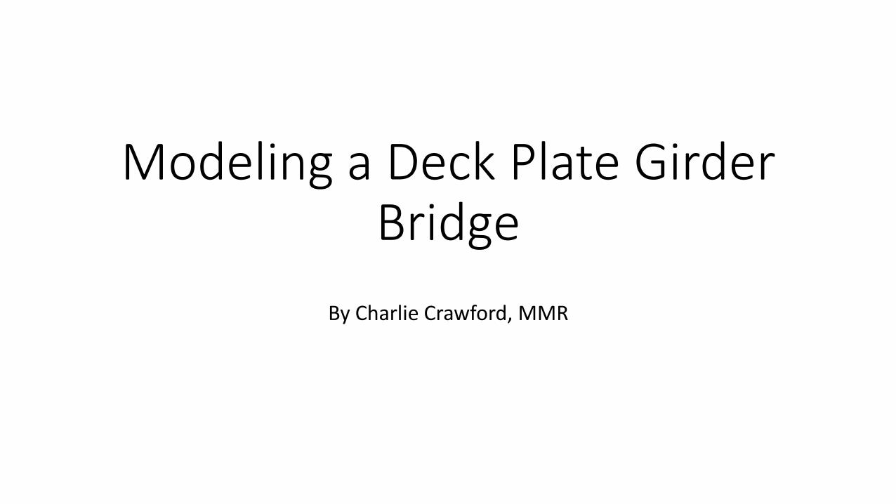
Bridges are everywhere. This is the St. Anthony Falls Bridge in Minneapolis. It is a post-tensioned
precast concrete box girder bridge.
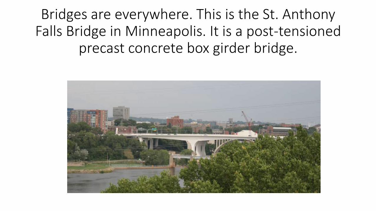
It’s on the same location as the I-35W Bridge before it’s 2007 collapse.
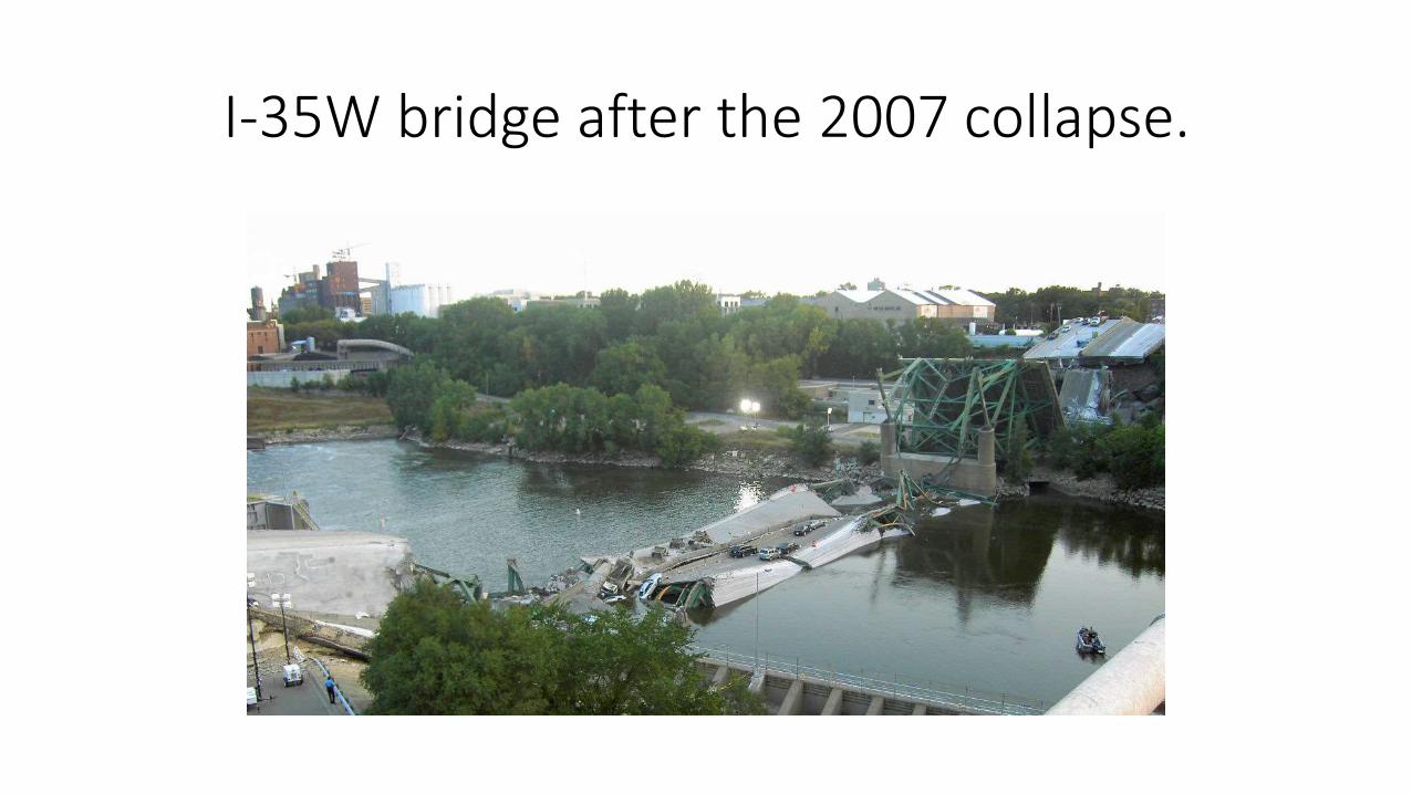
I-35W bridge after the 2007 collapse.
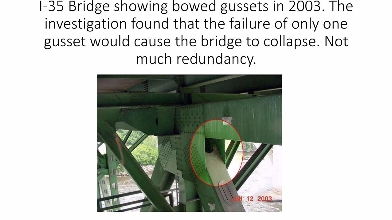
I-35 Bridge showing bowed gussets in 2003. The investigation found that the failure of only one gusset would cause the bridge to collapse. Not
much redundancy.
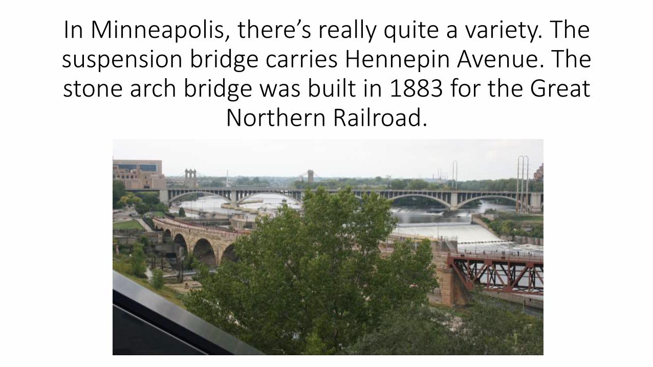
In Minneapolis, there’s really quite a variety. The suspension bridge carries Hennepin Avenue. The stone arch bridge was built in 1883 for the Great
Northern Railroad.
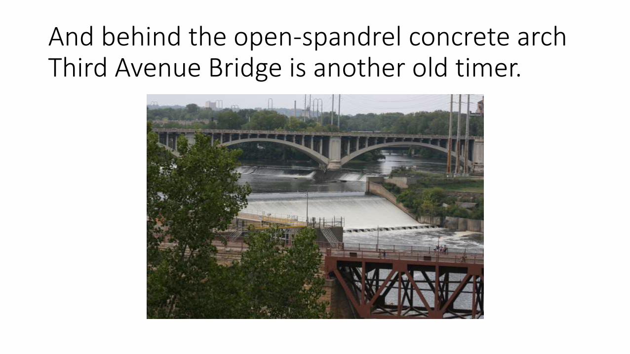
And behind the open-spandrel concrete arch Third Avenue Bridge is another old timer.
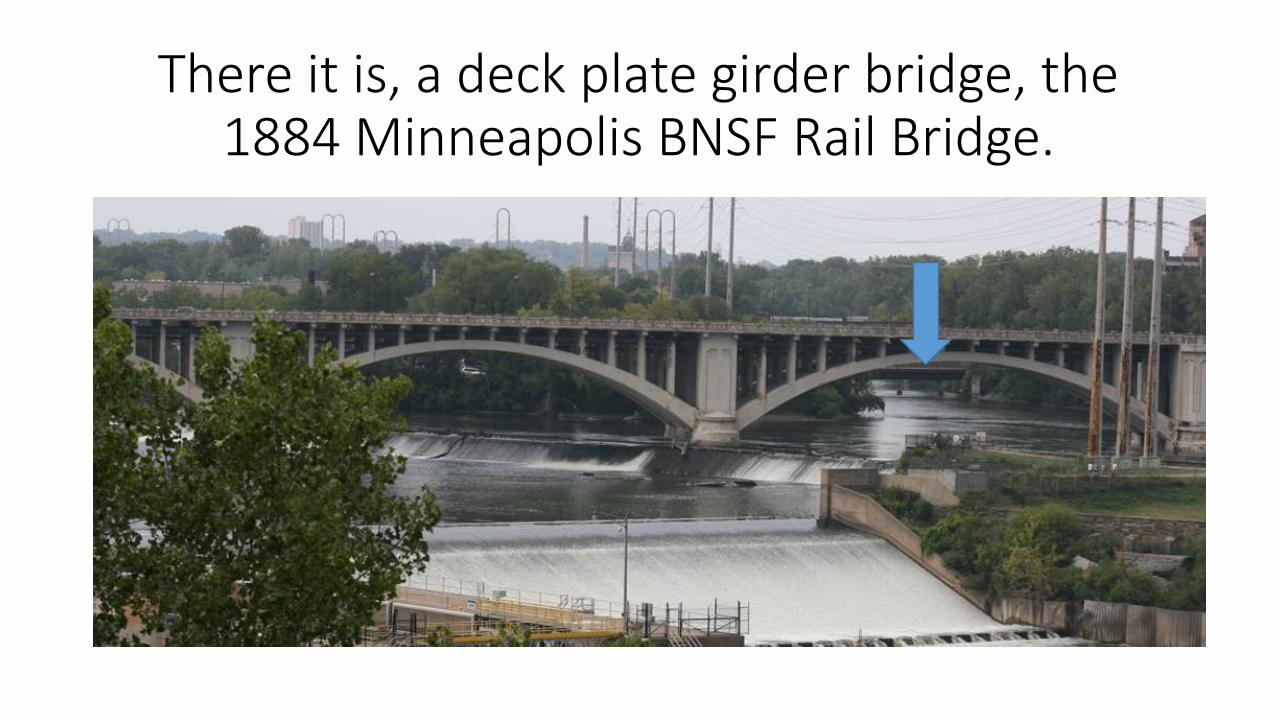
There it is, a deck plate girder bridge, the 1884 Minneapolis BNSF Rail Bridge.
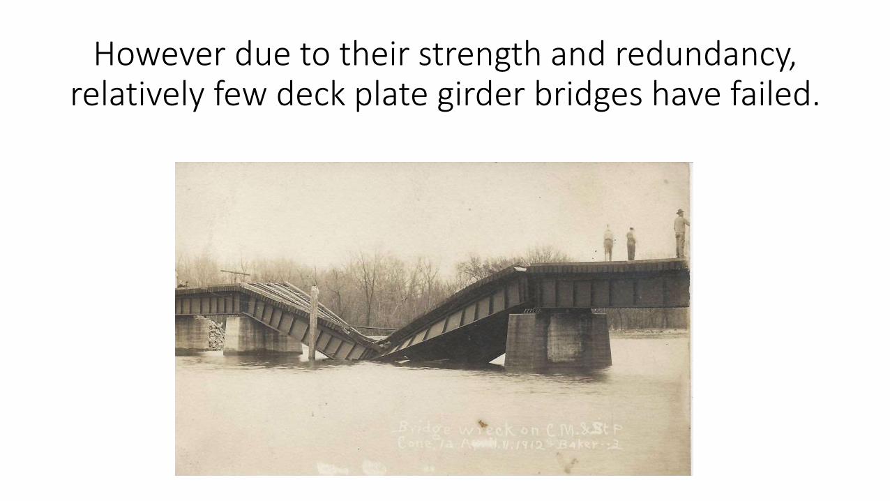
However due to their strength and redundancy, relatively few deck plate girder bridges have failed.
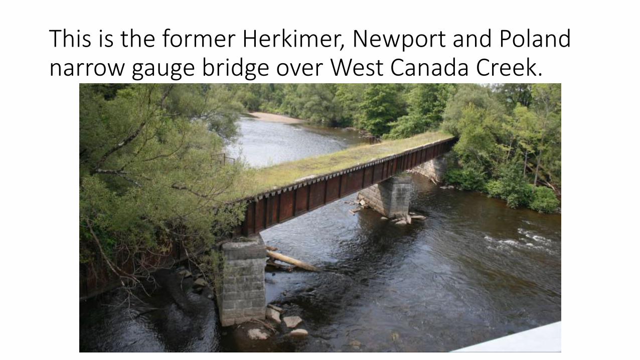
This is the former Herkimer, Newport and Poland narrow gauge bridge over West Canada Creek.
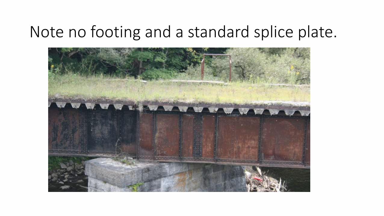
Note no footing and a standard splice plate.
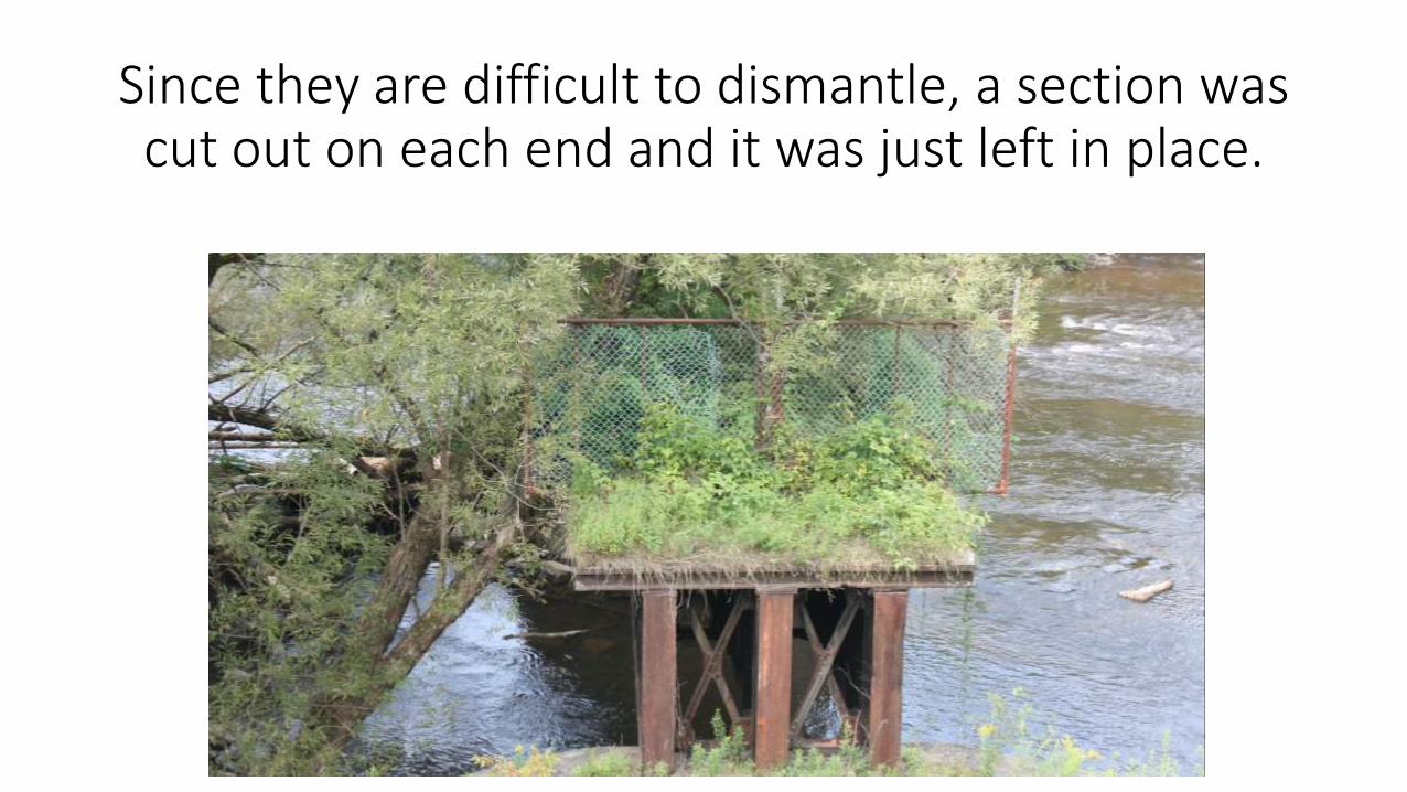
Since they are difficult to dismantle, a section was cut out on each end and it was just left in place.
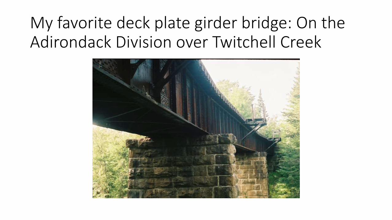
My favorite deck plate girder bridge: On the Adirondack Division over Twitchell Creek
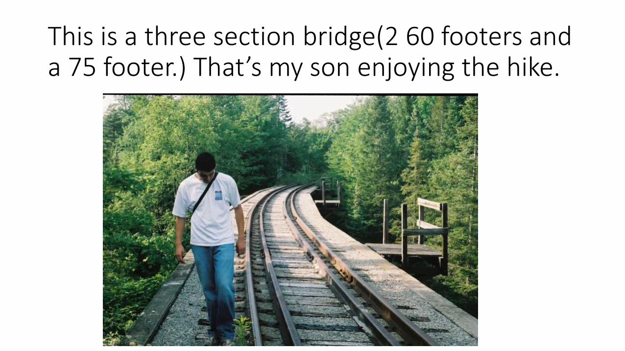
This is a three section bridge(2 60 footers and a 75 footer.) That’s my son enjoying the hike.

The bridge is reached after a two mile hike. It crosses Twitchell Creek with 40’ of clearance.
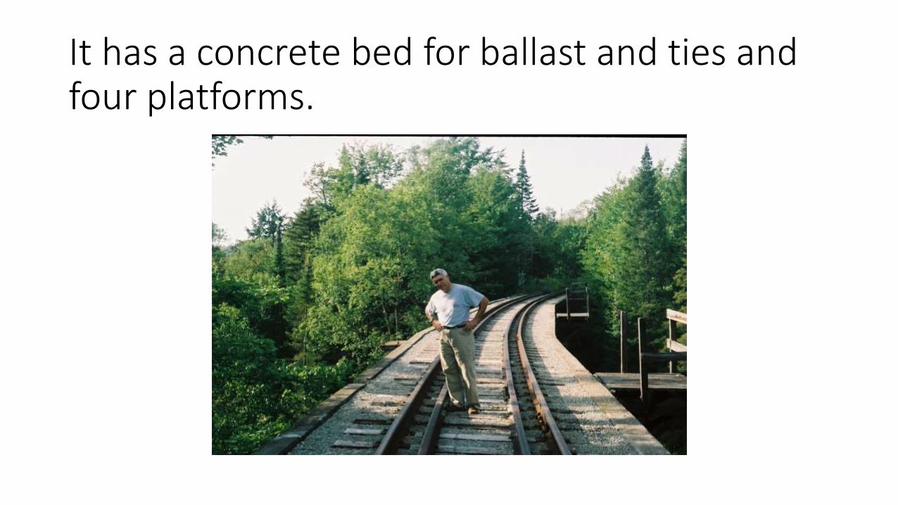
It has a concrete bed for ballast and ties and four platforms.

NMRA Data Sheets: a great member benefit

They are available to members the website, some quite dated and some with valuable prototype information.
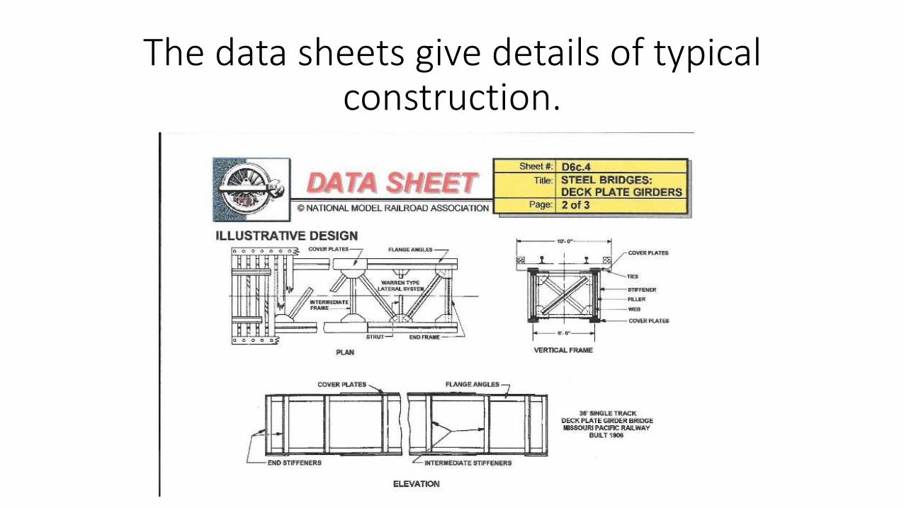
The data sheets give details of typical construction.
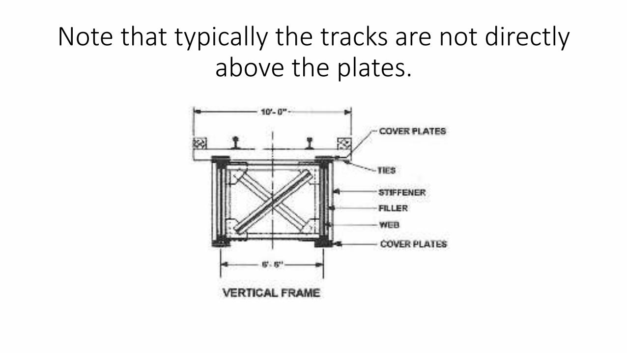
Note that typically the tracks are not directly above the plates.
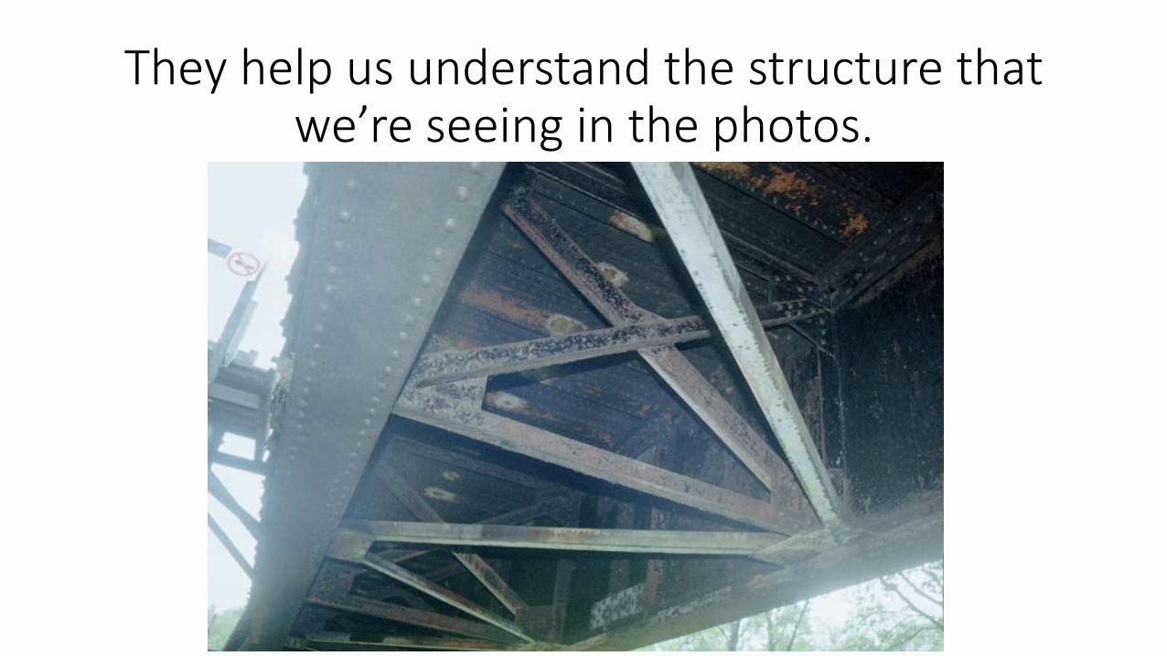
They help us understand the structure that we’re seeing in the photos.
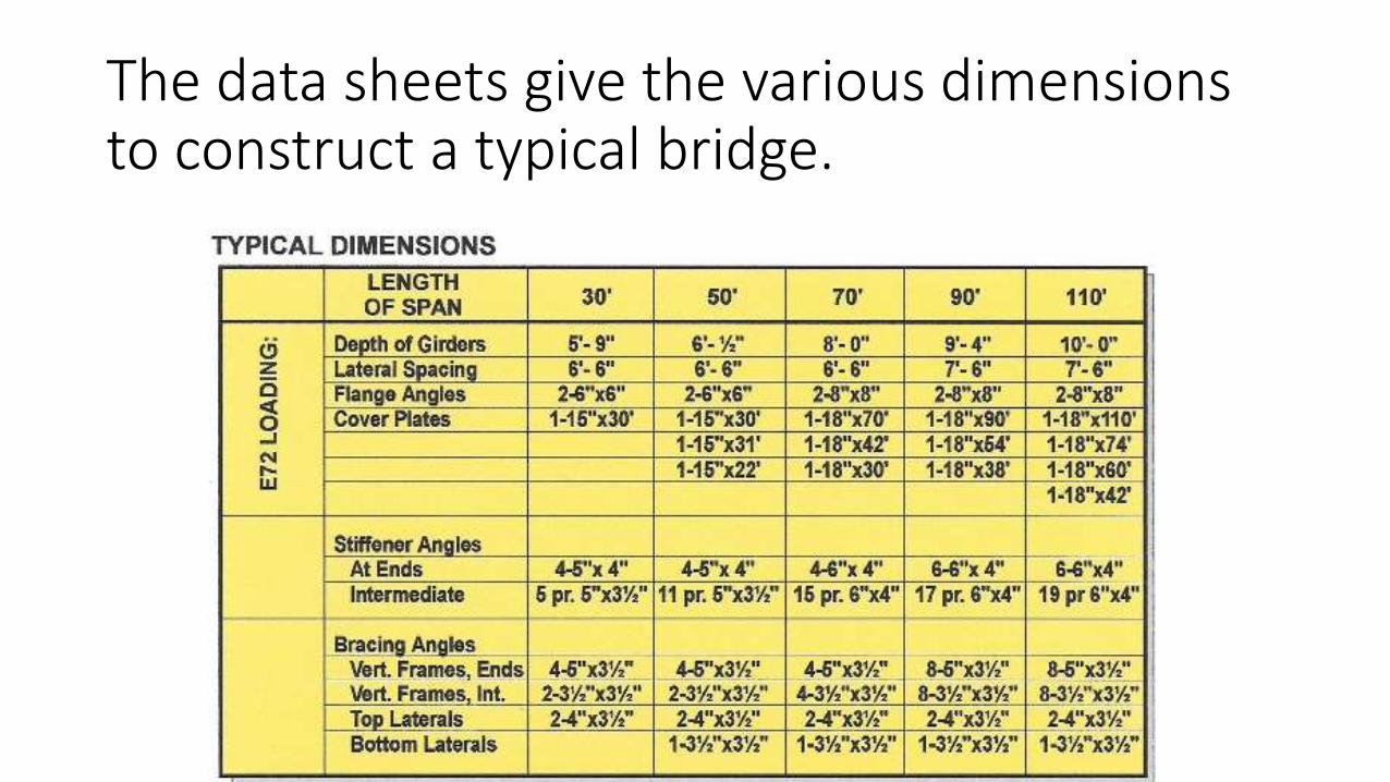
The data sheets give the various dimensions to construct a typical bridge.
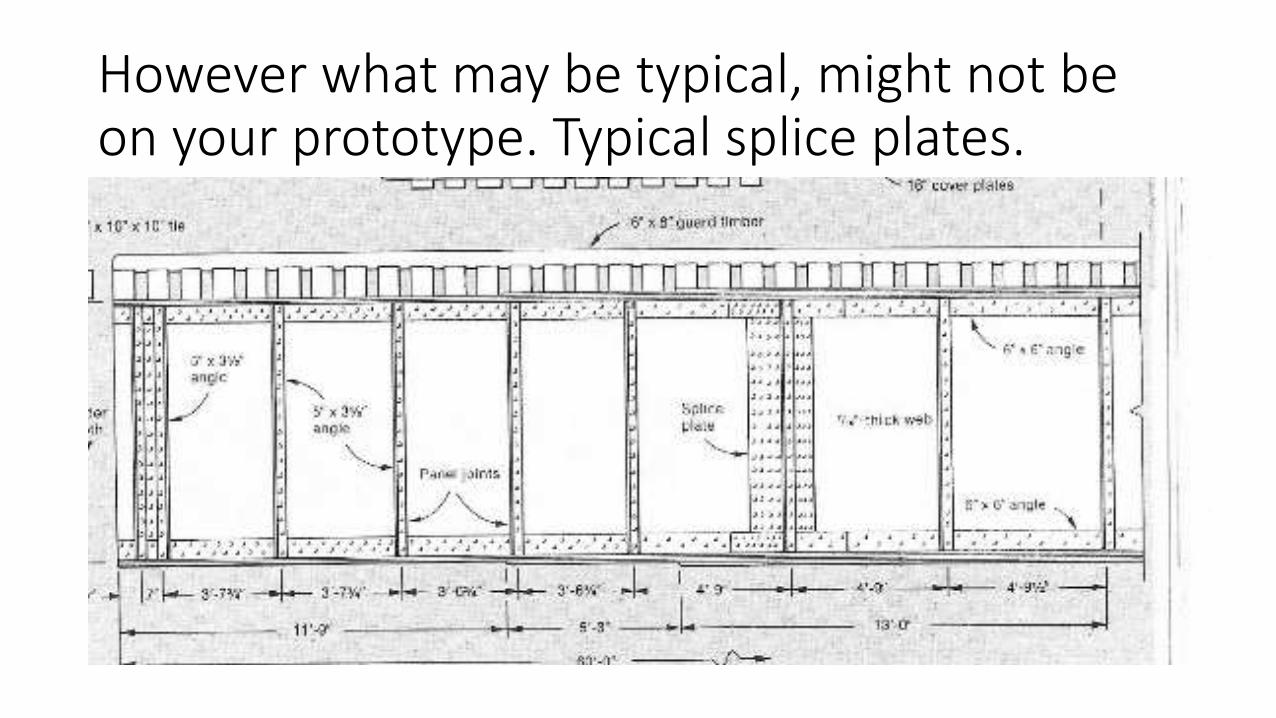
However what may be typical, might not be on your prototype. Typical splice plates.
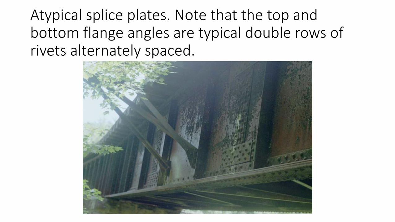
Atypical splice plates. Note that the top and bottom flange angles are typical double rows of rivets alternately spaced.
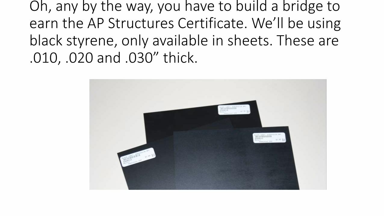
Oh, any by the way, you have to build a bridge to earn the AP Structures Certificate. We’ll be using black styrene, only available in sheets. These are .010, .020 and .030” thick.
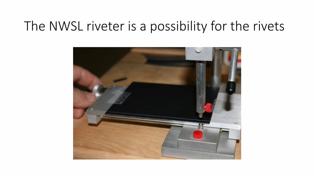
The NWSL riveter is a possibility for the rivets
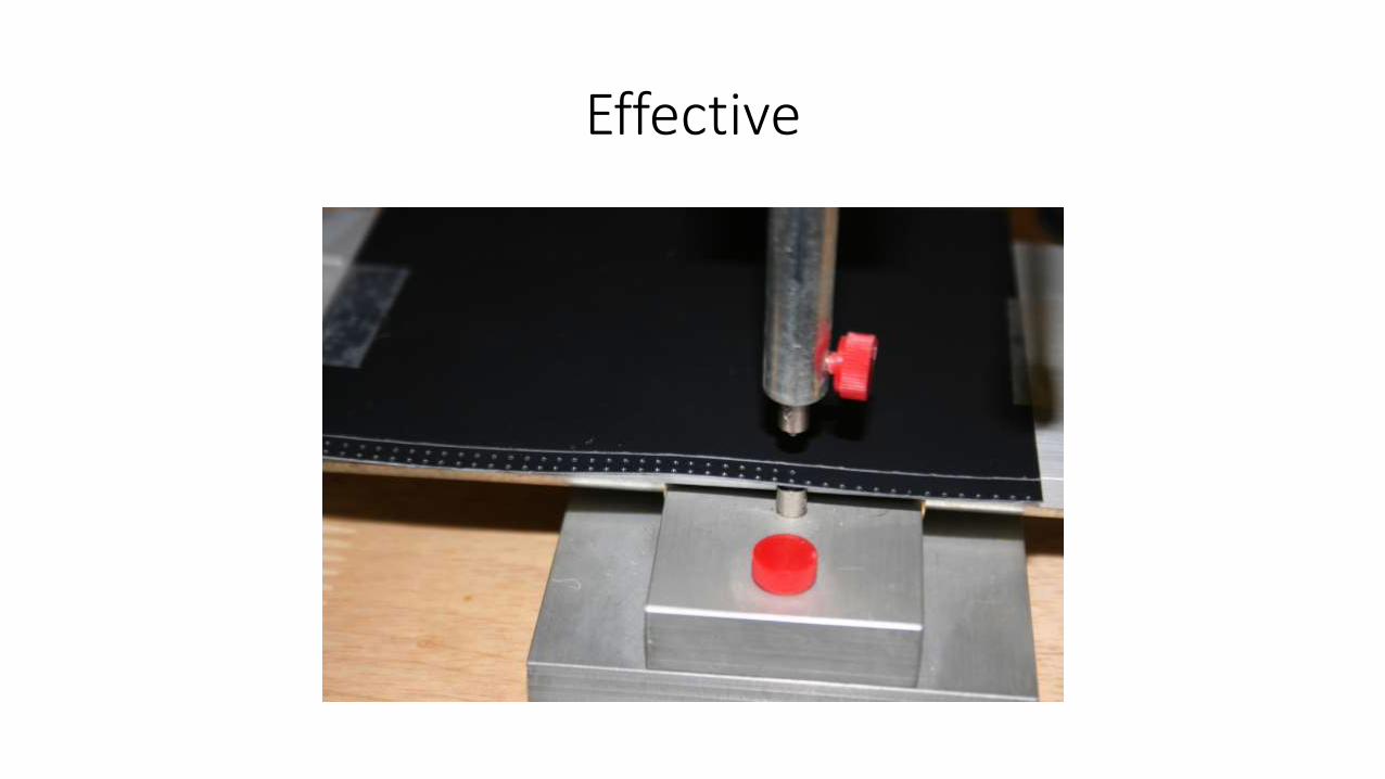
Effective
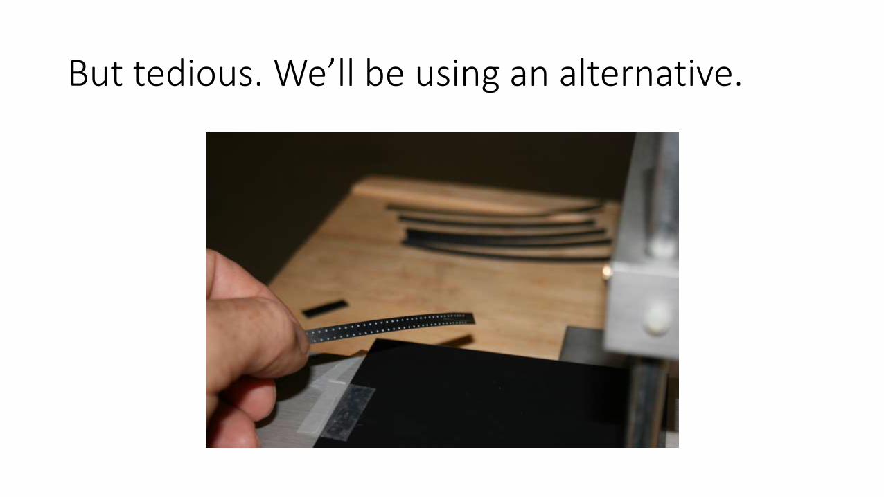
But tedious. We’ll be using an alternative.
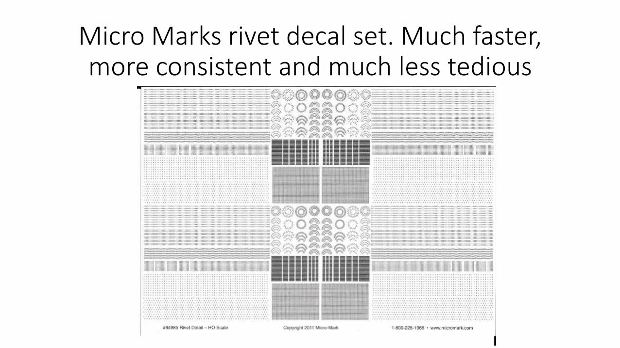
Micro Marks rivet decal set. Much faster, more consistent and much less tedious
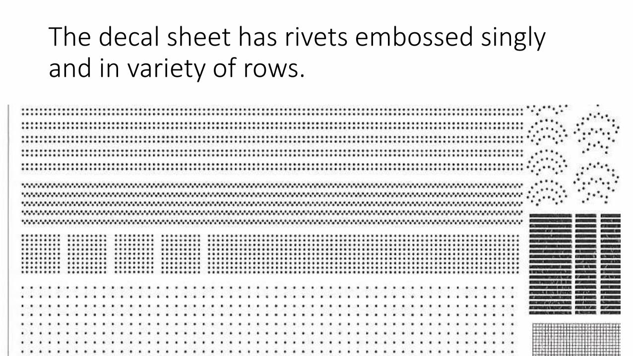
The decal sheet has rivets embossed singly and in variety of rows.
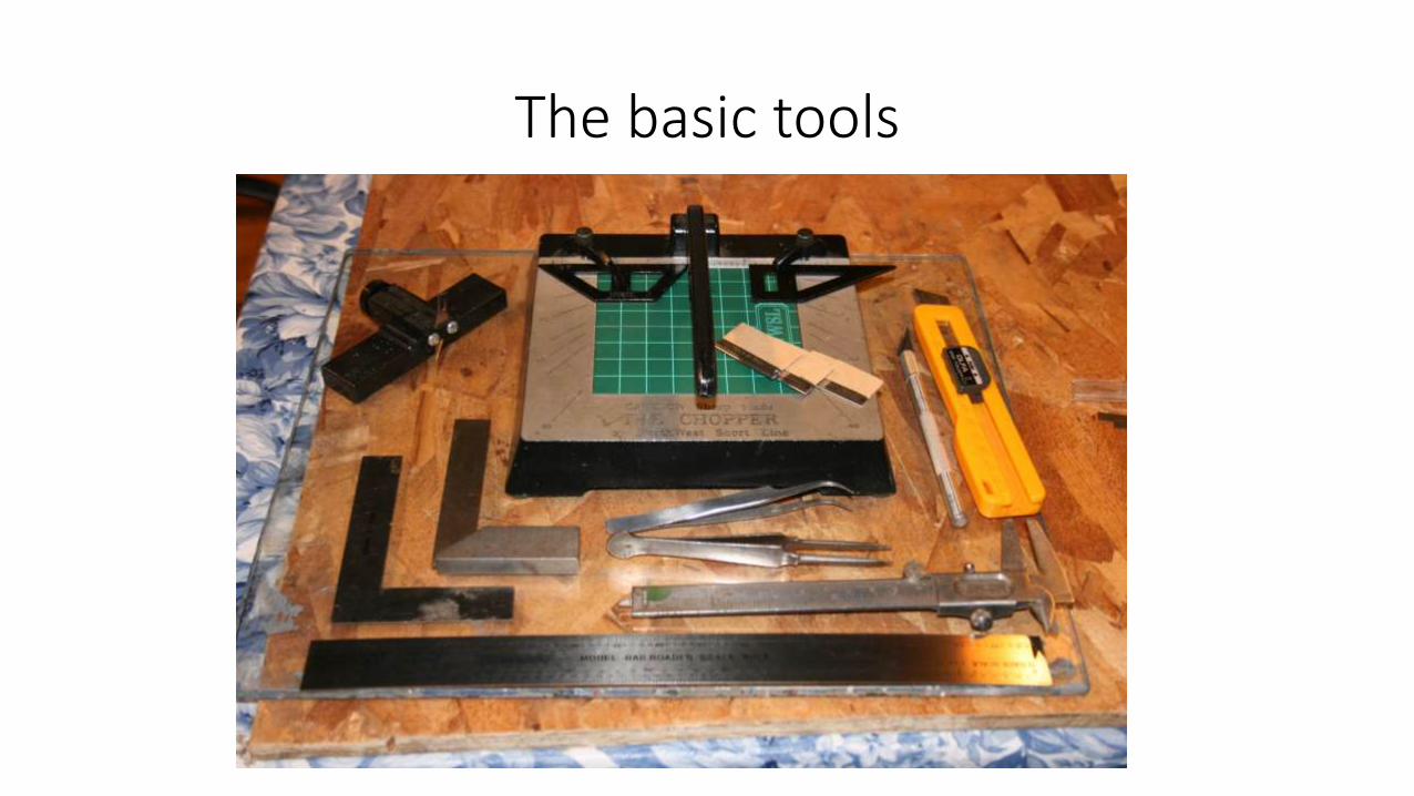
The basic tools
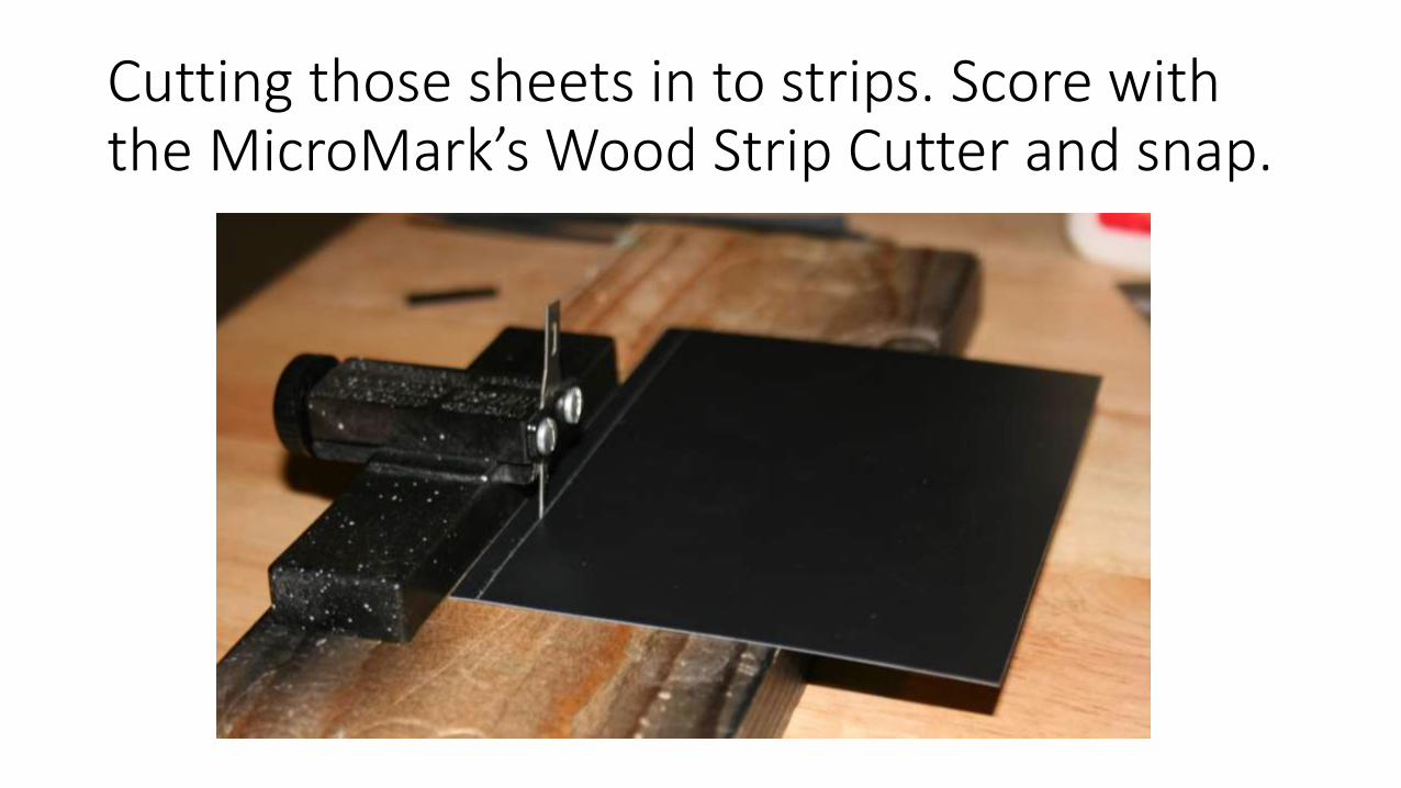
Cutting those sheets in to strips. Score with the MicroMark’s Wood Strip Cutter and snap.
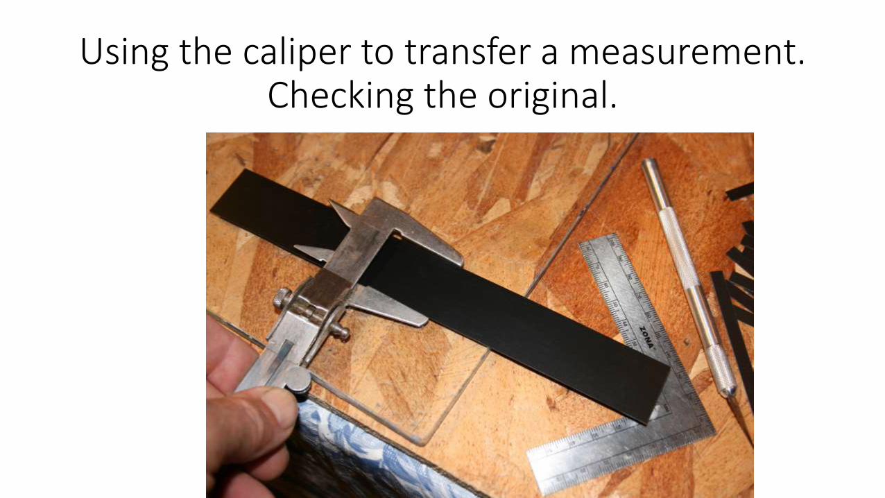
Using the caliper to transfer a measurement. Checking the original.
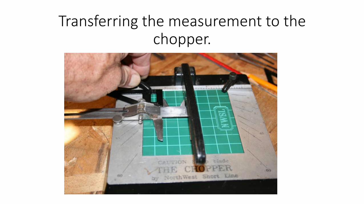
Transferring the measurement to the chopper.
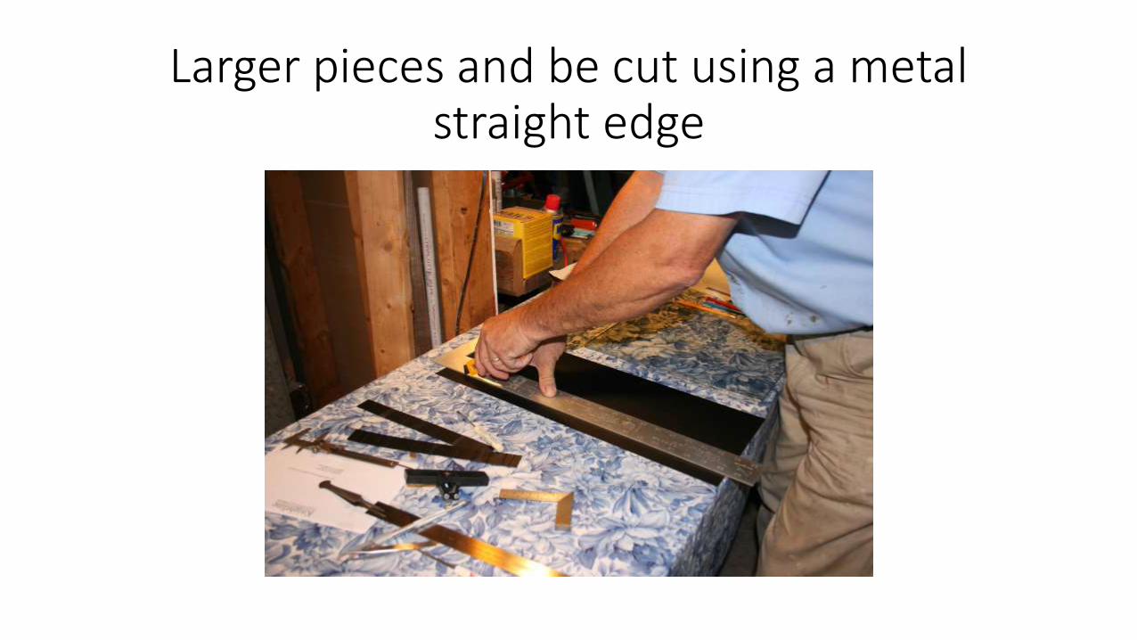
Larger pieces and be cut using a metal straight edge
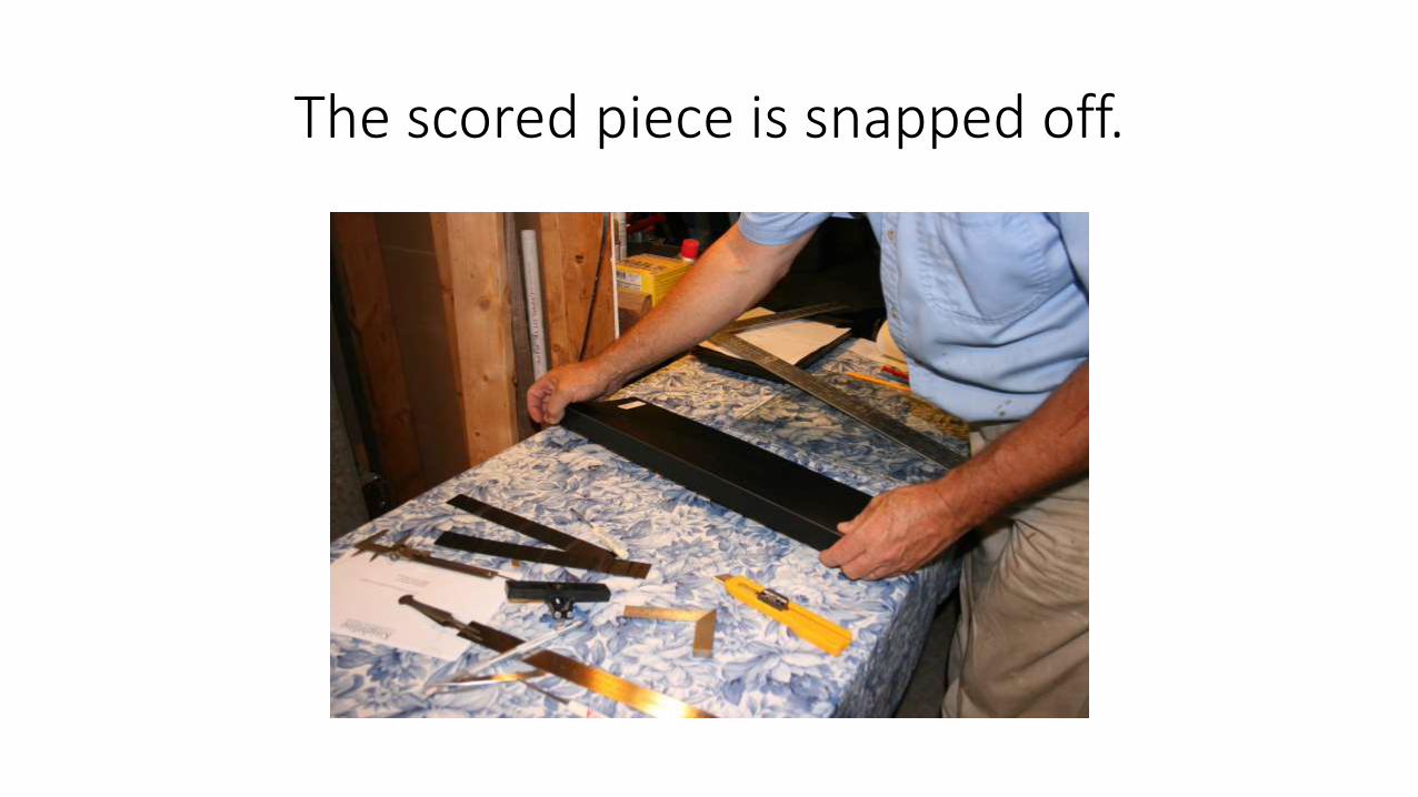
The scored piece is snapped off.
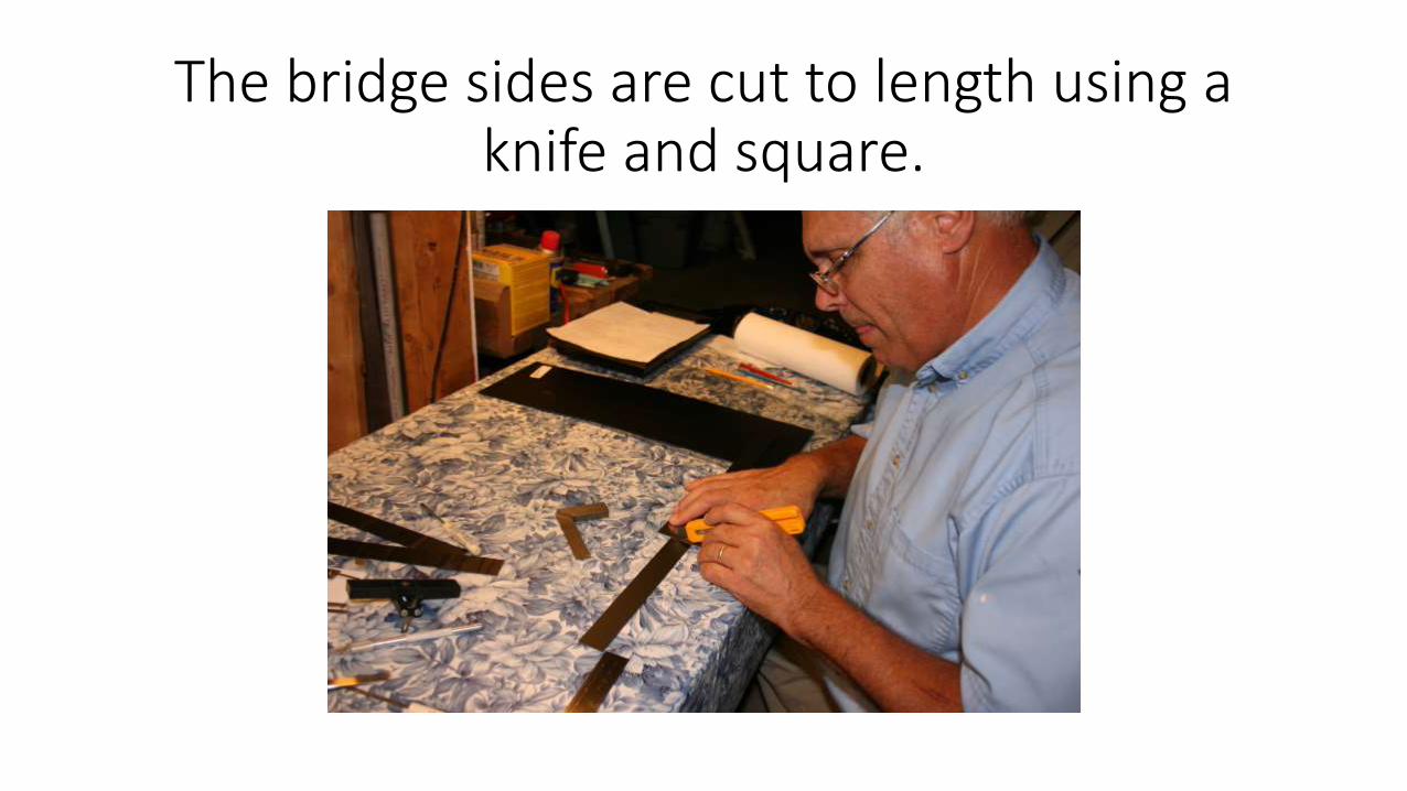
The bridge sides are cut to length using a knife and square.
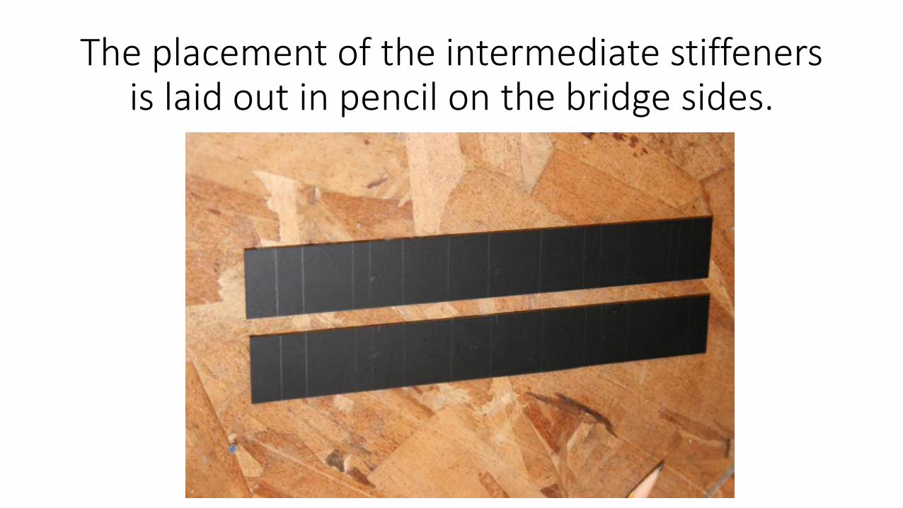
The placement of the intermediate stiffeners is laid out in pencil on the bridge sides.
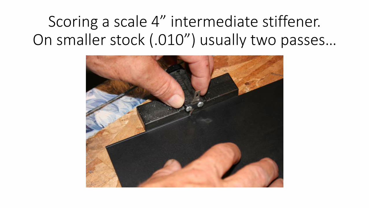
Scoring a scale 4” intermediate stiffener.On smaller stock (.010”) usually two passes…
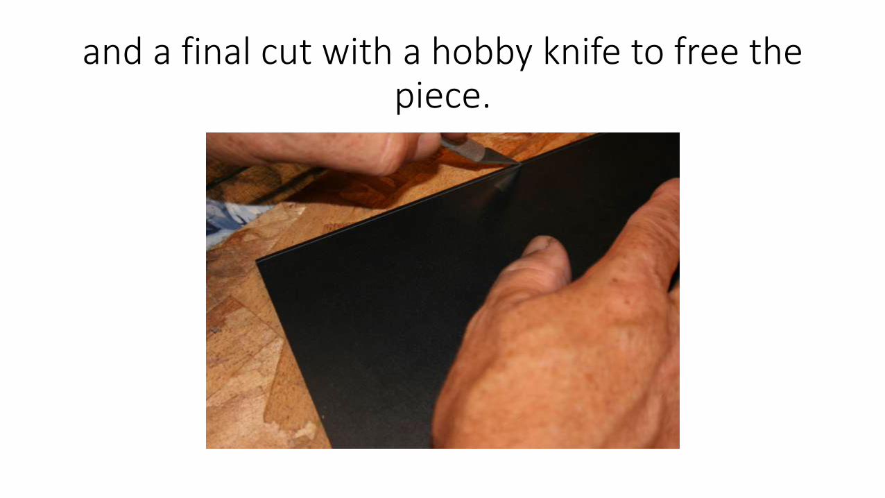
and a final cut with a hobby knife to free the piece.
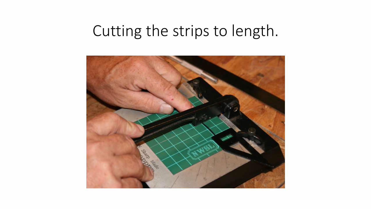
Cutting the strips to length.
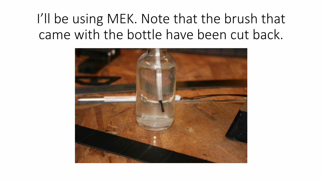
I’ll be using MEK. Note that the brush that came with the bottle have been cut back.
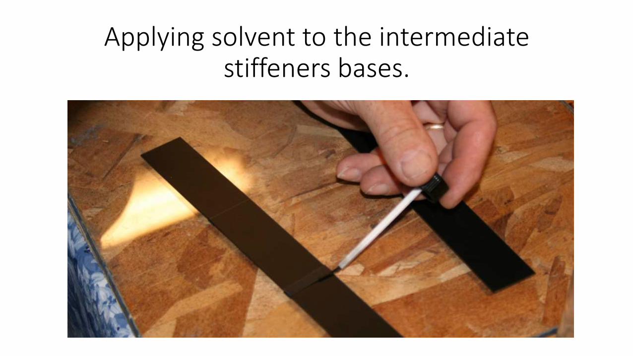
Applying solvent to the intermediate stiffeners bases.
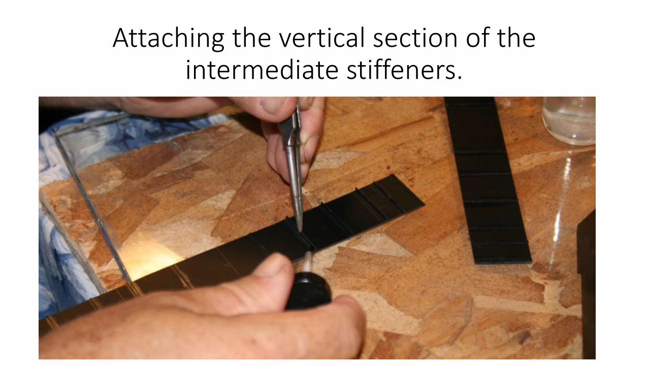
Attaching the vertical section of the intermediate stiffeners.
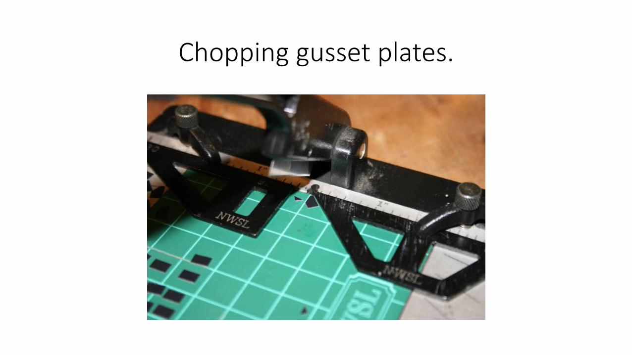
Chopping gusset plates.
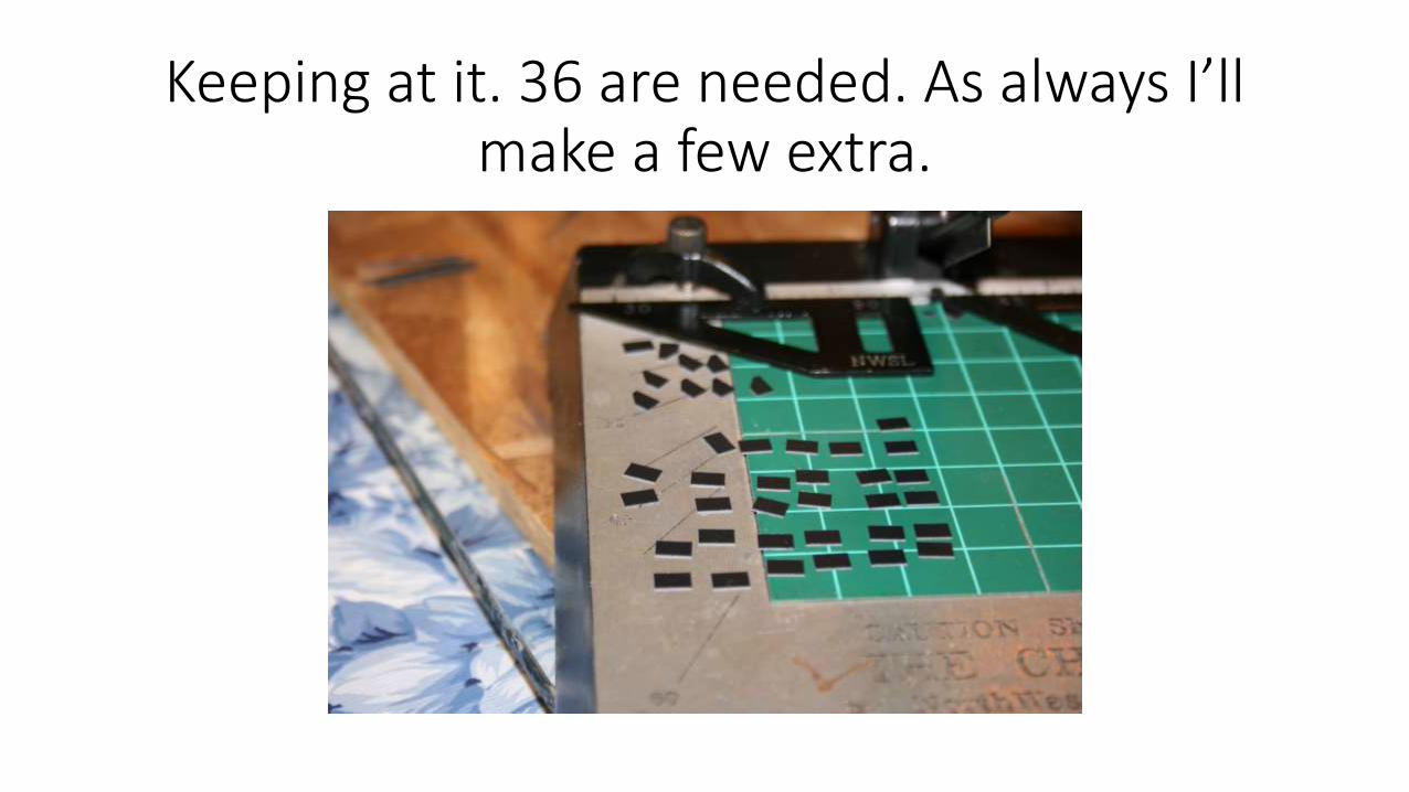
Keeping at it. 36 are needed. As always I’ll make a few extra.
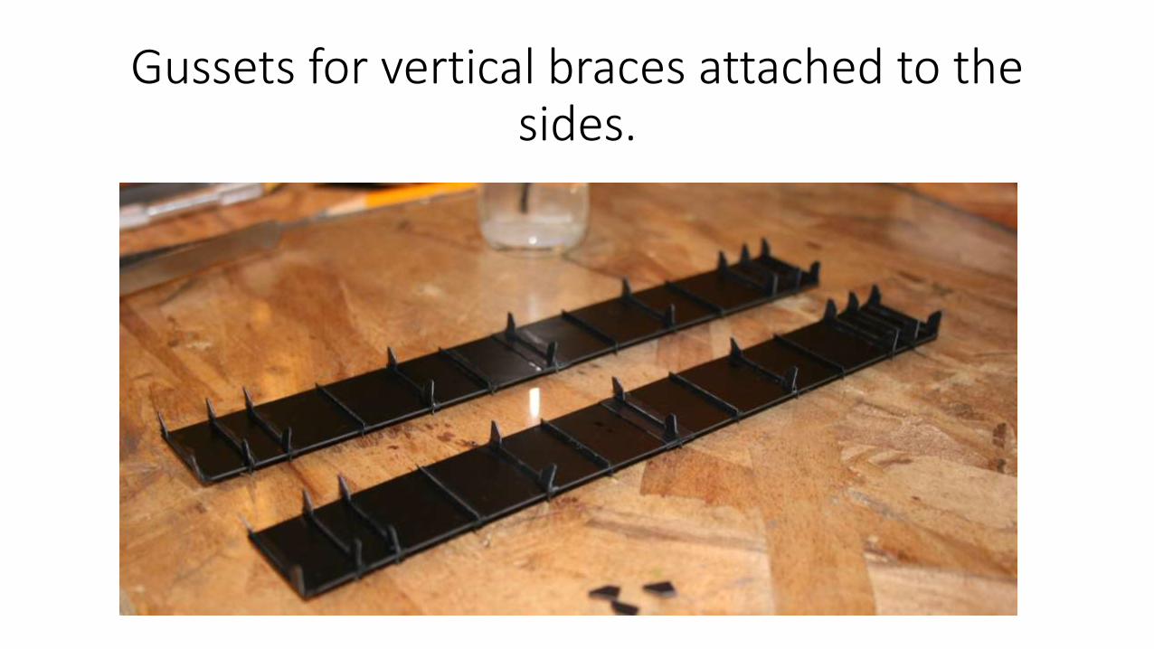
Gussets for vertical braces attached to the sides.
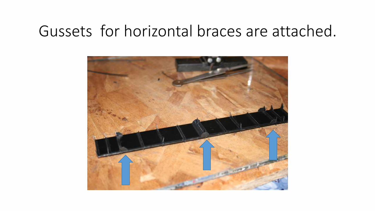
Gussets for horizontal braces are attached.
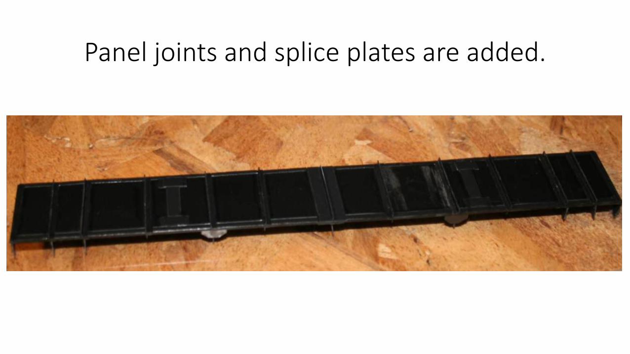
Panel joints and splice plates are added.
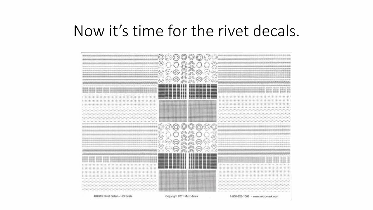
Now it’s time for the rivet decals.
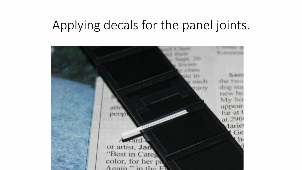
Applying decals for the panel joints.
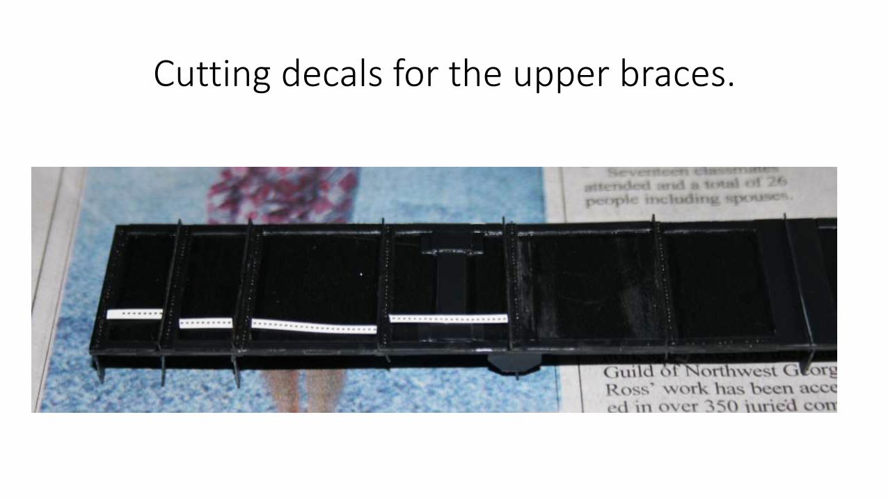
Cutting decals for the upper braces.
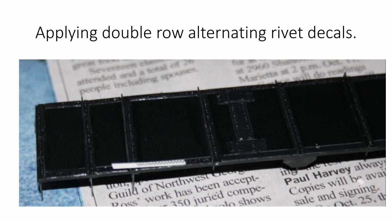
Applying double row alternating rivet decals.
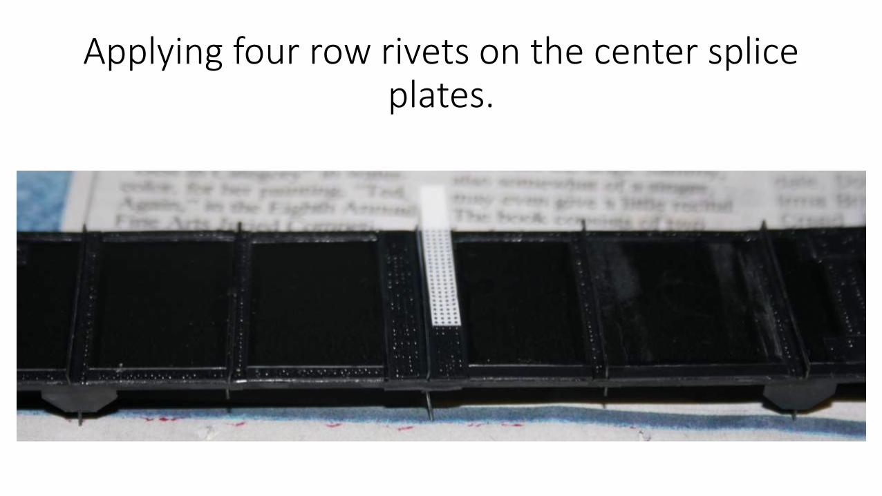
Applying four row rivets on the center splice plates.
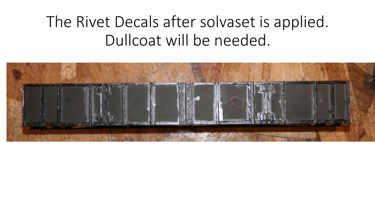
The Rivet Decals after solvaset is applied. Dullcoat will be needed.
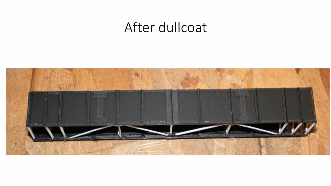
After dullcoat
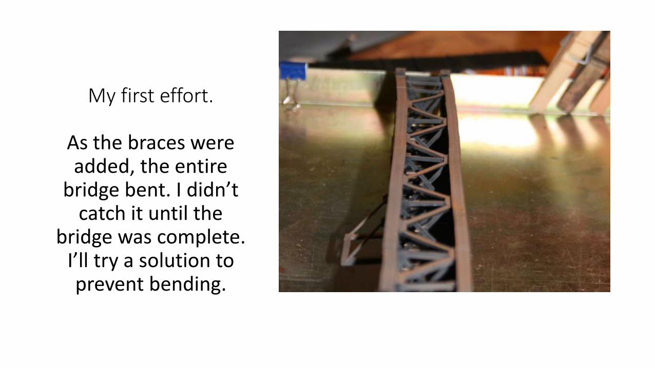
My first effort.
As the braces were added, the entire
bridge bent. I didn’t catch it until the
bridge was complete. I’ll try a solution to prevent bending.
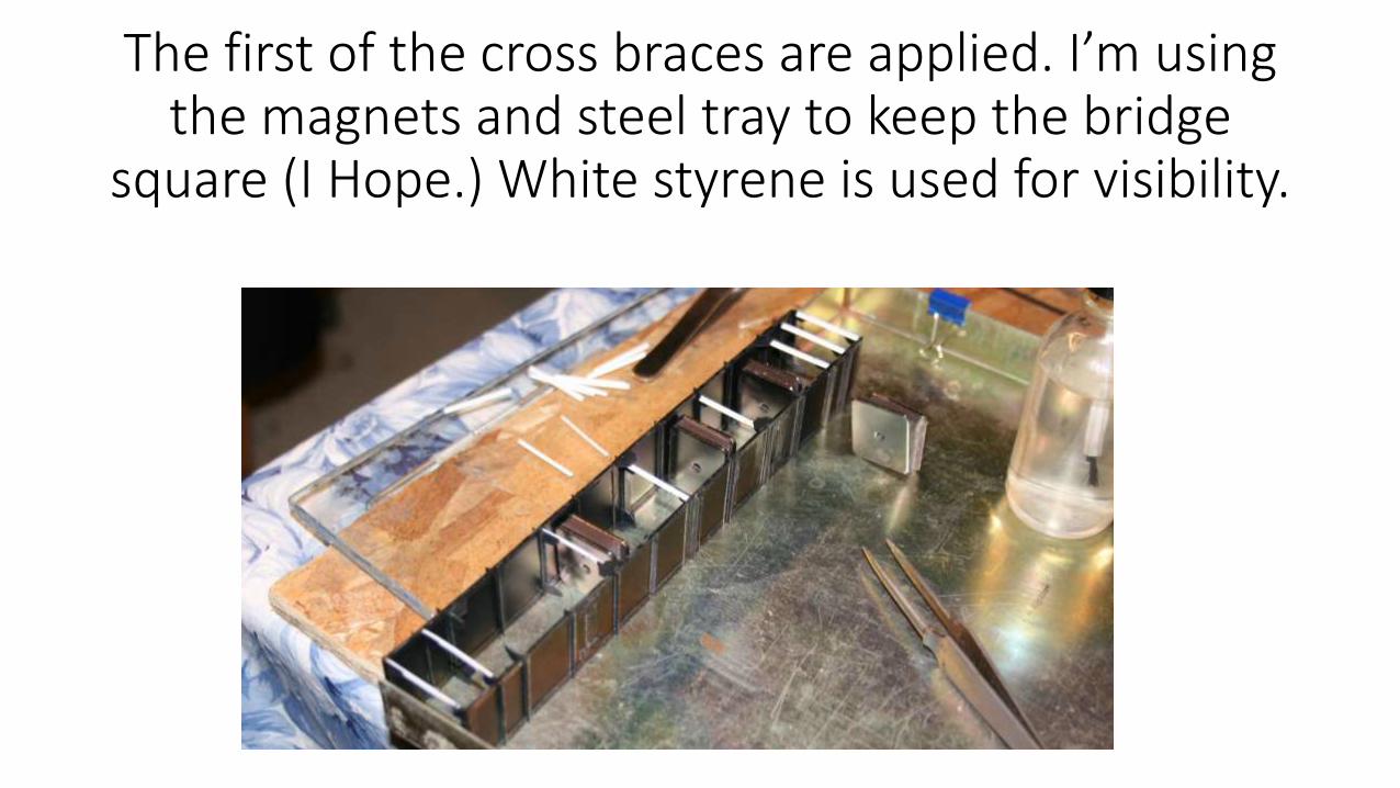
The first of the cross braces are applied. I’m using the magnets and steel tray to keep the bridge
square (I Hope.) White styrene is used for visibility.
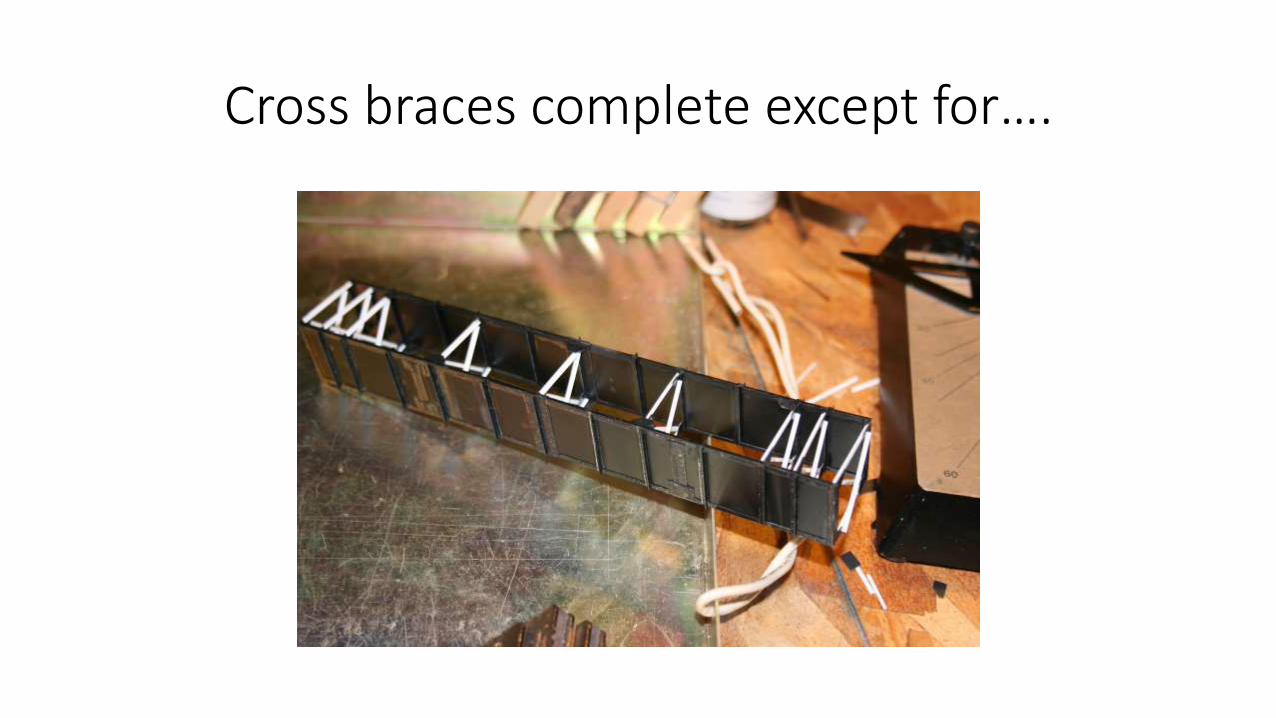
Cross braces complete except for….
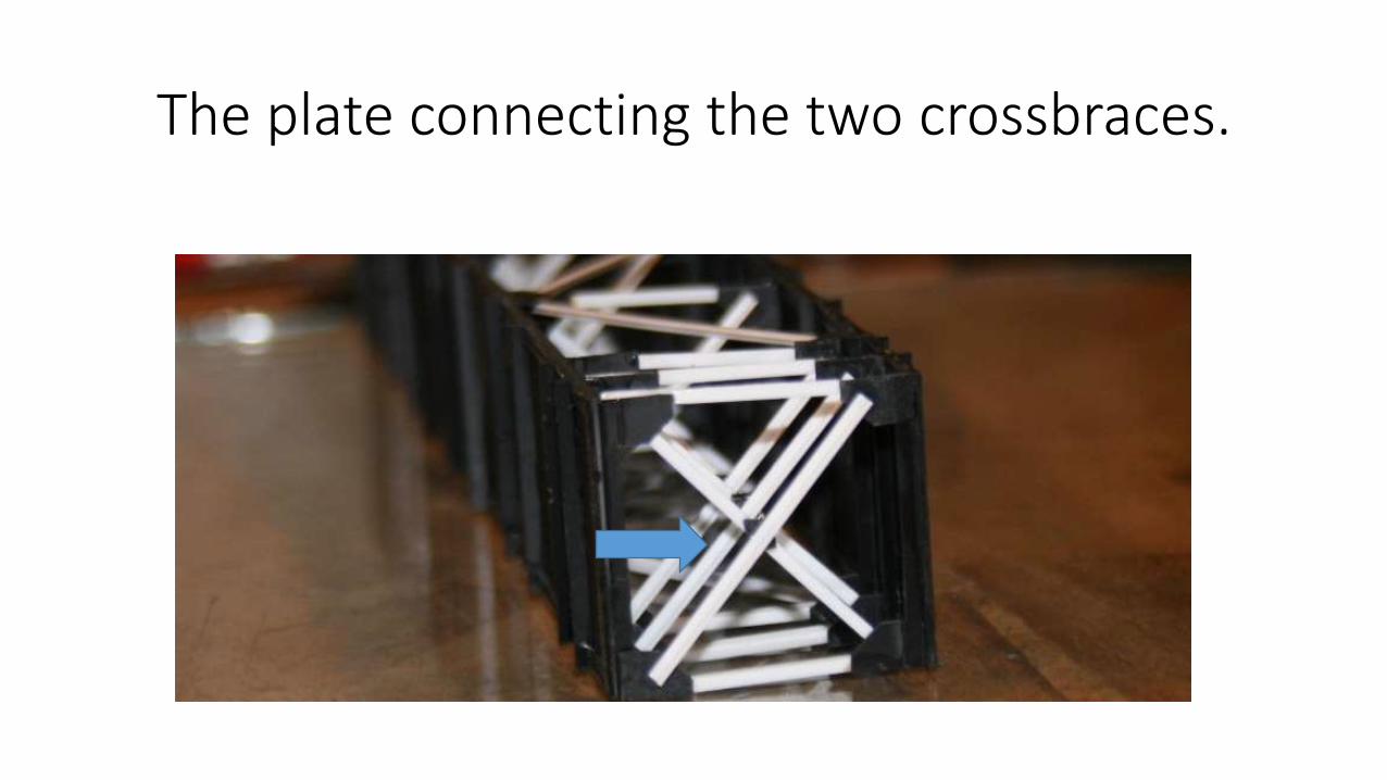
The plate connecting the two crossbraces.
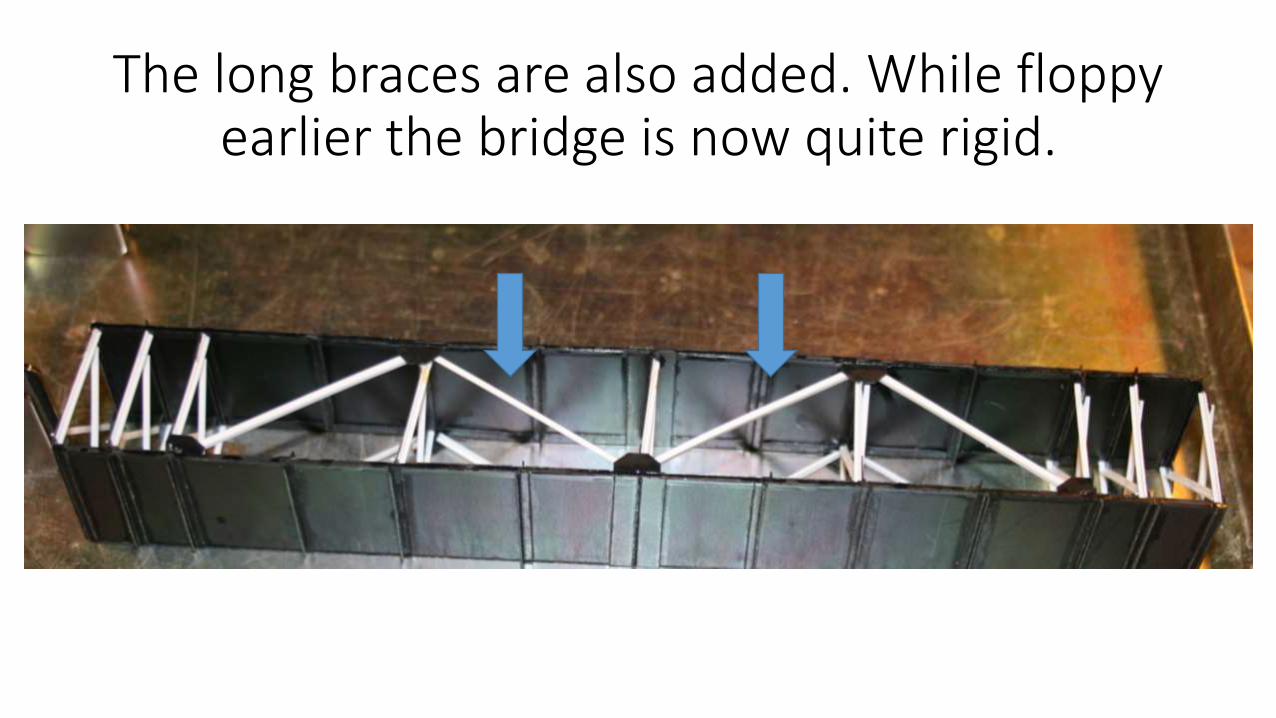
The long braces are also added. While floppy earlier the bridge is now quite rigid.
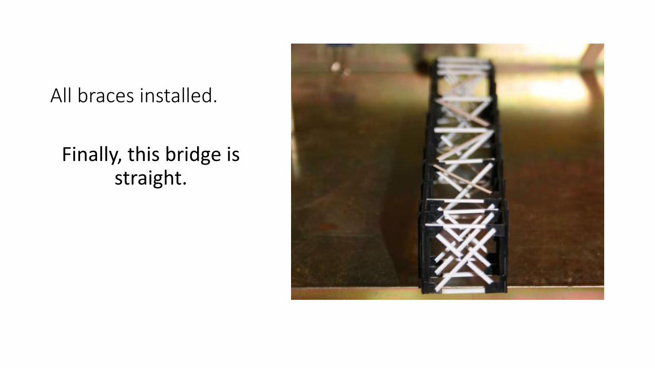
All braces installed.
Finally, this bridge is straight.
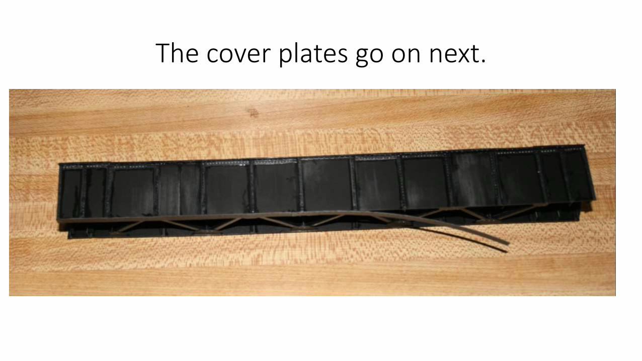
The cover plates go on next.
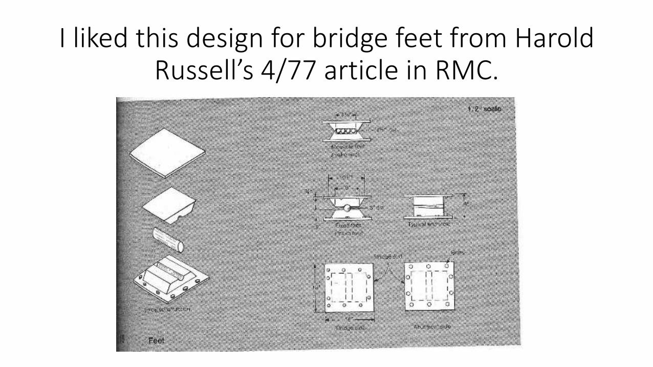
I liked this design for bridge feet from Harold Russell’s 4/77 article in RMC.
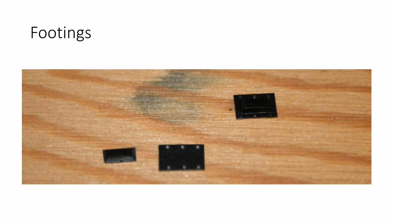
Footings
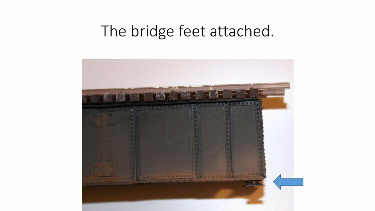
The bridge feet attached.
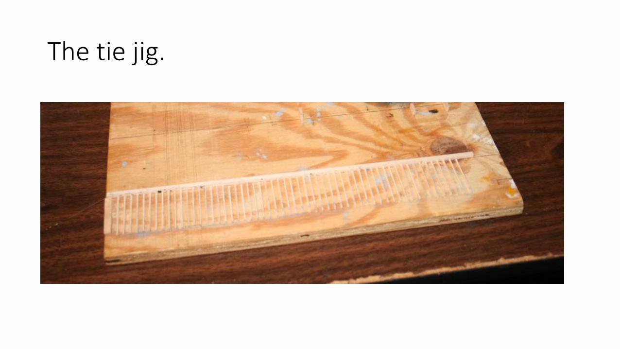
The tie jig.
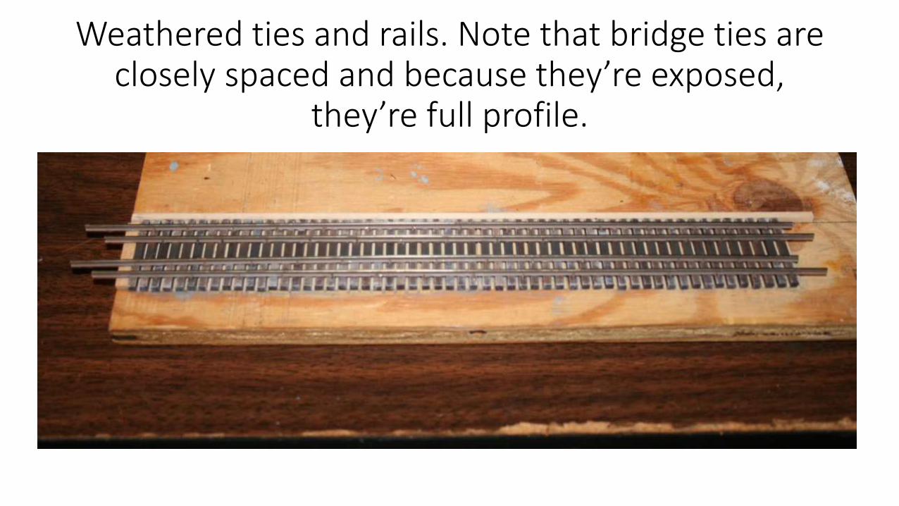
Weathered ties and rails. Note that bridge ties are closely spaced and because they’re exposed,
they’re full profile.
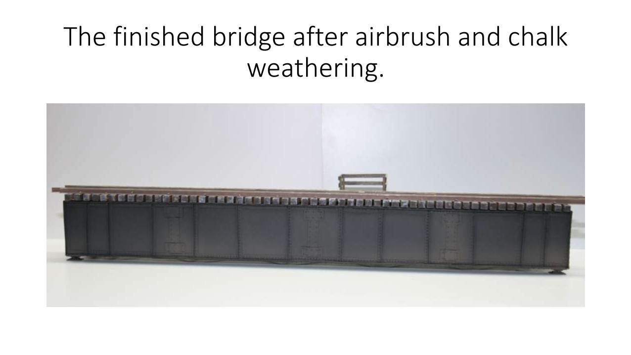
The finished bridge after airbrush and chalk weathering.
Sources
1. NMRA Data Sheet D4c.6: Steel Bridges: Deck Plate Girders 2/51
2. Railroad Model Craftsman Apr. 1977 Harold R. Russell “Building a deck plate girder bridge. Pages 54-59
3. Model Railroader Oct.1988 Harold R. Russell “Deck Bridges and Moveable Spans. Pages 100-106
4. Personal pictures taken on field trip to Twitchell Creek Bridge July 2009
5. Wikipedia: Minneapolis Mississippi River bridges.