Embed Size (px)
Citation preview

Chap. 9.2 SR3500 Fuselage Assembly - Cabin
MODEL: SR3500 ©1997-2006 Murphy Aircraft Mfg. Ltd. All rights reserved
26/06/2006 Page 1

Chap. 9.2 SR3500 Fuselage Assembly - Cabin
MODEL: SR3500 ©1997-2006 Murphy Aircraft Mfg. Ltd. All rights reserved
26/06/2006 Page 2

Chap. 9.2 SR3500 Fuselage Assembly - Cabin
MODEL: SR3500 ©1997-2006 Murphy Aircraft Mfg. Ltd. All rights reserved
26/06/2006 Page 3

Chap. 9.2 SR3500 Fuselage Assembly - Cabin
MODEL: SR3500 ©1997-2006 Murphy Aircraft Mfg. Ltd. All rights reserved
26/06/2006 Page 4
Parts List for Gear Box
No. Part Number Description Qty Required1,23 FUS0711QL BRACING CHANNEL 22,22 FUS0711QR BRACING CHANNEL 2
3 FUS301QB CARRYTHROUGH 14 FUS0814QR CARRYTHROUGH PLATE 15 FUS0814QL CARRYTHROUGH PLATE 16 FUS0318Q CARRYTHROUGH 27 FUS1003Q ANGLE (CUT RAWST0006 TO 43.25") 18 FUS0310B LANDING GEAR CLAMP PLATE 29 FUS0309B LANDING GEAR CLAMP 210 FL0400 FLOAT MOUNTING BRACKET (OPTIONAL) 0 (OR 4)*11 FUS0331 LANDING GEAR ATTACH BRACKET 212 FUS0307Q CARRYTHROUGH 213 FUS1004Q ANGLE (CUT RAWST0006 TO 39.94") 114 FUS0301QA CARRYTHROUGH 115 FUS0813QR CARRYTHROUGH PLATE 116 FUS0813QL CARRYTHROUGH PLATE 117 FUS0871 SPRING GEAR BRACE FITTING 218 FUS0704 STRUT FITTING 219 FUS0703Q STRUT FITTING 220 FUS0702Q STRUT FITTING 221 W0719 WASHER 1.812 DIA X .125 THK 2
AN3-5A BOLT 24AN3-6A BOLT 24AN5-13A BOLT 16 (OR 6)*AN5-14A BOLT 2 (OR 0)*AN5-15A BOLT 2AN5-16A BOLT 2 (OR 12)*AN5-17A BOLT 2AN5-20A BOLT 2AN6-13A BOLT 8AN6-17A BOLT 4AN6-45A BOLT 4AN9-12A BOLT 2AN9-13A BOLT 2AN9-17A BOLT 2AN365-524 FIBER NUT 24AN365-624 FIBER NUT 16MS21044N9 FIBER NUT 6AN365-1032 FIBER NUT 48AN960-10 WASHER 48AN960-516 WASHER 24AN960-616 WASHER 16AN960-916 WASHER 10RV-1613 AVEX RIVET 42RV-1619 AVEX RIVET 46
* For float option

Chap. 9.2 SR3500 Fuselage Assembly - Cabin
MODEL: SR3500 ©1997-2006 Murphy Aircraft Mfg. Ltd. All rights reserved
26/06/2006 Page 5

Chap. 9.2 SR3500 Fuselage Assembly - Cabin
MODEL: SR3500 ©1997-2006 Murphy Aircraft Mfg. Ltd. All rights reserved
26/06/2006 Page 6
9.2 Cabin Assembly
The SR3500 Cabin area is described as a Tail Dragger configuration. Trike Gear differences are
noted. Read through this entire section carefully before you start work to see how the sections fit
together.
1) Cleco two shear webs (FUS0325L and FUS0325R) to the carrythrough (flanges facing out). Ensure
the shear webs are vertical then drill remaining holes to #40. Figure 9.2.4
2) Drill a fifth hole in each FUS0325 and carrythrough. Figure 9.2.4
Fig. 9.2.4
3) Drill each hole out to #11.
4) Place the FUS0325 shear webs aside for now.
NOTE: In the Taildragger SR, there are five FUS0302 carrythroughs. Each of these must have
the rudder cable holes drilled. One at a time, cleco back to back a FUS0302 to a FUS0301 and
drill. Do not drill the wire loom and brake line holes.
5) In the trike SR, there are four FUS0302 carrythroughs and two FUS0301 remaining undrilled. Drill
the rudder cable holes in each.
6) Place the five FUS0302’s aside for now.
7) Cut two lengths of 1” x 1” x 1/8” angle (RAWST0006) to 43 ¼” long.
NOTE: For a trike you will need to cut four lengths at 43 ¼” long.
8) Center one of the 43 ¼” angles on the top of a FUS0301 carrythrough. Figure 9.2.5
9) Ensure the top edges are flush then backdrill through the carrythrough into the angle. Figure 9.2.5

Chap. 9.2 SR3500 Fuselage Assembly - Cabin
MODEL: SR3500 ©1997-2006 Murphy Aircraft Mfg. Ltd. All rights reserved
26/06/2006 Page 7
Fig. 9.2.5
10) Repeat for each FUS0301 carrythrough. There will be two for a taildragger and four for a trike.
11) Cleco carrythrough (FUS0307-please note on later kits this is replaced by two laminations,
FUS0307-1) to the trimmed carrythrough (FUS0301) and angle.
NOTE: FUS0307 must go between FUS0301 and the angle. Figure 9.2.6
Fig. 9.2.6

Chap. 9.2 SR3500 Fuselage Assembly - Cabin
MODEL: SR3500 ©1997-2006 Murphy Aircraft Mfg. Ltd. All rights reserved
26/06/2006 Page 8
12) Using carrythrough (FUS0307) as a drill guide, back drill FUS0301 as in Figure 9.2.6. When
drilling the 5/16” and 3/8” holes it is best to drill to “F” first then to final size.
13) Bolt the three Stn 100 gussets (FUS0308, FUS0312 and FUS0313) temporarily to the assembly
with two ¼” bolts. Figure 9.2.7
HINT: When bolting together items that must later come apart, use enough washers under the
nuts to prevent the plastic part of the nut from coming in contact with the thread. This will save
wear on the nuts as well as speed things up. Using castle nuts also will work.
Fig. 9.2.7
14) Drill out the open holes to 5/16”. Use 5/16” bolts to hold together. Remove ¼” bolts and drill out
the two remaining holes. Figure 9.2.8
Fig. 9.2.8

Chap. 9.2 SR3500 Fuselage Assembly - Cabin
MODEL: SR3500 ©1997-2006 Murphy Aircraft Mfg. Ltd. All rights reserved
26/06/2006 Page 9
15) Repeat for other side.
16) Cleco carrythrough (FUS0318-replaced by two FUS0318-1’s on later kits) to the other FUS0301
and angle and drill as in Figure 9.2.9.
NOTE: The two carrythrough structures assembled with FUS0307 and FUS0318 will be used to
build up the landing gear box for the taildragger SR3500. This same box is used to carry the shear
load in the floor structure. Therefore, it is also used in the trike. The trike must also have another
similar box made up but using carrythroughs FUS0317. See step 17.
Fig. 9.2.9
17) Cleco a carrythrough (FUS0317) to a FUS0301 and drill as in Figure 9.2.10. Repeat for both
FUS0317s.
18) Disassemble the FUS0307 and FUS0318 carrythrough structures.

Chap. 9.2 SR3500 Fuselage Assembly - Cabin
MODEL: SR3500 ©1997-2006 Murphy Aircraft Mfg. Ltd. All rights reserved
26/06/2006 Page 10
Fig. 9.2.10
19) Debur, chromate and rivet structures back together with 3/16” avex rivets. Figure 9.2.12
20) Bolt the landing gear brackets (FUS0309) and (FUS0331) in place as in Exploded view at the first
page of this section and Figure 9.2.12. Use AN365 fibernuts and AN 960 washers. The nuts
should go to the inside of the torsion box.
NOTE: It is easier to put all the bolts in place before tightening .

Chap. 9.2 SR3500 Fuselage Assembly - Cabin
MODEL: SR3500 ©1997-2006 Murphy Aircraft Mfg. Ltd. All rights reserved
26/06/2006 Page 11
Fig. 9.2.12
21) If building a trike, repeat steps 18-21 for the two FUS0317 carrythrough assemblies. See rivet and
bolt pattern in Figure 9.2.13.

Chap. 9.2 SR3500 Fuselage Assembly - Cabin
MODEL: SR3500 ©1997-2006 Murphy Aircraft Mfg. Ltd. All rights reserved
26/06/2006 Page 12
Fig. 9.2.13
22) Set the landing gear boxes aside.
23) Cleco an upright (FUS0346 L or R) back to back with a FUS0302 carrythrough. Use a carpenter’s
square to insure the upright is perpendicular. Back drill #30 holes, then out to #11. Figure 9.2.14
Fig. 9.2.14

Chap. 9.2 SR3500 Fuselage Assembly - Cabin
MODEL: SR3500 ©1997-2006 Murphy Aircraft Mfg. Ltd. All rights reserved
26/06/2006 Page 13
24) Repeat for opposite end.
25) Repeat steps 23 & 24 for two more FUS0302 carrythroughs.
26) Make a fourth assembly but with the flanges facing the same direction. To do this you must trim
the inner flange of the uprights.
27) Cutting the flanges off the upright reduces its strength so a doubler must be added to increase it.
Figure 9.2.15. Make the doublers from .032” material (RAWST0010). Later kits have these
doublers made (FUS0811).
Fig. 9.2.15
28) Label the four upright assemblies #5,6,7, and 8 with the one with the flanges facing the same
direction and doublers as #8.
29) The two FUS0302 carrythroughs at station #7 and #8 must have four stringer notches cut out of
each. Cleco #7 and #8 FUS0302 together back to back as in Figure 9.2.16. Scribe the stringer
notches from one FUS0302 to the other FUS0302. Turn the assembly and scribe the other
FUS0302.

Chap. 9.2 SR3500 Fuselage Assembly - Cabin
MODEL: SR3500 ©1997-2006 Murphy Aircraft Mfg. Ltd. All rights reserved
26/06/2006 Page 14
Fig. 9.2.16
30) Move the front facing FUS0302 to the other end of the rearward facing FUS0302 and scribe.
31) Cut out the scribed areas of both parts. The finished part should look like Figure 9.2.17.
Fig. 9.2.17
32) Debur, chromate and rivet together station #5 and #6 carrythroughs and uprights with 3/16 avex
rivets.
NOTE: Steps 38 to 44 are for mounting the float attach brackets. The brackets come standard in
the kit. If the aircraft will never be on floats they are not necessary. Not putting them in will save 2-
3 hours work and approximately 1 pound in weight. WARNING: They will be very difficult to put in
after the aircraft is built.
33) Cut off flush the two center tabs on each end of station #8 carrythrough. Figure 9.2.18

Chap. 9.2 SR3500 Fuselage Assembly - Cabin
MODEL: SR3500 ©1997-2006 Murphy Aircraft Mfg. Ltd. All rights reserved
26/06/2006 Page 15
Fig. 9.2.18
34) Cleco station #8 carrythrough, uprights and float attach brackets (FUS0347) together as in
Figure 9.2.19.
Fig. 9.2.19
35) Cleco station #7 carrythrough and uprights to the float attach brackets. The flanges of both
carrythroughs will face the same direction.

Chap. 9.2 SR3500 Fuselage Assembly - Cabin
MODEL: SR3500 ©1997-2006 Murphy Aircraft Mfg. Ltd. All rights reserved
26/06/2006 Page 16
36) Drill out the float attach brackets from both sides to #11.
37) Drill out the two mounting holes on each side to 5/16” as shown in Figure 9.2.19.
38) Disassemble.
39) From the firewall channel (FUS0386) make up two elevator horn brackets as in Figure 9.2.20. Later
kits have this part made, FUS0812.
Fig. 9.2.20
40) Rivet a bell crank bearing (MI0025) to each horn (FUS0304) as in Figure 9.2.21. Make one left
and one right assembly. Use 1/8” S.S. rivets.

Chap. 9.2 SR3500 Fuselage Assembly - Cabin
MODEL: SR3500 ©1997-2006 Murphy Aircraft Mfg. Ltd. All rights reserved
26/06/2006 Page 17
Fig. 9.2.21
41) Bolt the horn assemblies and horn brackets together as in Figure 9.2.22.
Fig. 9.2.22
42) Drill four #40 holes in station #8 carrythrough as shown in Figure 9.2.23.

Chap. 9.2 SR3500 Fuselage Assembly - Cabin
MODEL: SR3500 ©1997-2006 Murphy Aircraft Mfg. Ltd. All rights reserved
26/06/2006 Page 18
Fig. 9.2.23
43) Cleco a FUS0321 shear web with the flanges facing out to two of the holes just drilled. Drill back
through the shear web the three open holes. Repeat for the other two holes in the carrythrough.
44) Cleco station #8 and #7 carrythroughs back to back and transfer the holes just drilled into station
#7 carrythrough. Disassemble.
45) Center the horn-bracket assembly over the holes in station #8 carrythrough and back drill the
brackets. Notice the center of the horns should be offset vertically 1/8” from the center of the
carrythrough. Figure 9.2.24
Fig. 9.2.24
46) Drill two extra holes in the ends of each bracket . Figure 9.2.24
47) Cleco the FUS0321 shear webs back in place and take all holes out to #11. Disassemble.

Chap. 9.2 SR3500 Fuselage Assembly - Cabin
MODEL: SR3500 ©1997-2006 Murphy Aircraft Mfg. Ltd. All rights reserved
26/06/2006 Page 19
48) Bend the tabs over 90º on the shear webs as in Figure 9.2.25. The exact location is not important
for it is done only to provide some stiffness.
Fig. 9.2.25
49) Rivet the two shear webs, horn-bracket assembly and station #8 carrythrough together with 3/16
avex rivets.
50) Rivet the uprights and doublers to station #8 carrythrough with 3/16 avex rivets. Do not rivet in the
area where the float attach brackets will go.
51) Rivet station #7 uprights and carrythrough together. Do not rivet in the area of the float attach
brackets.
52) The floor structure can now be clecoed together. Start at the front with the FUS0325 shear webs
and work towards the back. The shear web flanges will have to be drilled out to #30 before being
clecoed in place. A rule of thumb is the flanges always face the side of the aircraft they are closest
to. Figure 9.2.26. NOTE: For trike gear see Figure 9.2.27.

Chap. 9.2 SR3500 Fuselage Assembly - Cabin
MODEL: SR3500 ©1997-2006 Murphy Aircraft Mfg. Ltd. All rights reserved
26/06/2006 Page 20
Fig. 9.2.26
Fig. 9.2.27

Chap. 9.2 SR3500 Fuselage Assembly - Cabin
MODEL: SR3500 ©1997-2006 Murphy Aircraft Mfg. Ltd. All rights reserved
26/06/2006 Page 21
53) Drill out all shear webs and carrythroughs to #11.
54) Rivet the shear webs in place with appropriate length 3/16” avex rivets.
NOTE: If building a trike, use AN3 bolts, fiber nuts and washers instead of rivets to connect the
two center FUS0325’s to station #2 carrythrough..
55) Cut two 56 ¾” lengths from FUS1044(formerly RAWST0005 3/4 x 3/4 x 1/8 angle). These will be
used as shear web caps on the outer side of the outside shear webs.
56) Clamp the two angles to the outside edges of the outside shear webs. Figure 9.2.28. NOTE: The
top surfaces of the angles should be level with the carrythroughs, not with the shear webs.
Fig. 9.2.28
57) Using the shear webs as drill guides, back drill the angles to #40. Remove.
58) Cut two 92 1/4” lengths of angle. Position and drill as in Figure 9.2.29. Do not drill any holes aft
of station 8.
Fig. 9.2.29
Chap. 9.2 SR3500 Fuselage Assembly - Cabin
MODEL: SR3500 ©1997-2006 Murphy Aircraft Mfg. Ltd. All rights reserved
26/06/2006 Page 22
59) Reposition the two 56 ¾ lengths with the 92 1/4” lengths and drill out to #30.
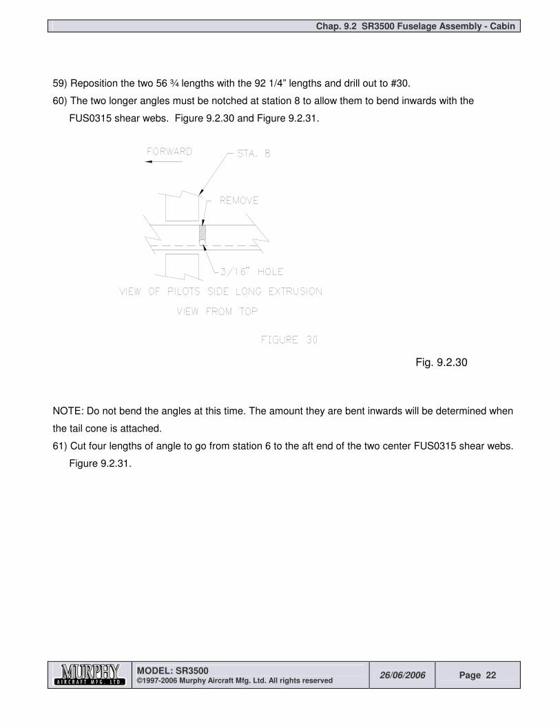
60) The two longer angles must be notched at station 8 to allow them to bend inwards with the
FUS0315 shear webs. Figure 9.2.30 and Figure 9.2.31.
Fig. 9.2.30
NOTE: Do not bend the angles at this time. The amount they are bent inwards will be determined when
the tail cone is attached.
61) Cut four lengths of angle to go from station 6 to the aft end of the two center FUS0315 shear webs.
Figure 9.2.31.

Chap. 9.2 SR3500 Fuselage Assembly - Cabin
MODEL: SR3500 ©1997-2006 Murphy Aircraft Mfg. Ltd. All rights reserved
26/06/2006 Page 23
Fig. 9.2.31
62) Drill only #40 holes to position and cleco in place. The final drilling will be done after the tail cone is
installed.
63) Remove the floor assembly from the workbench.
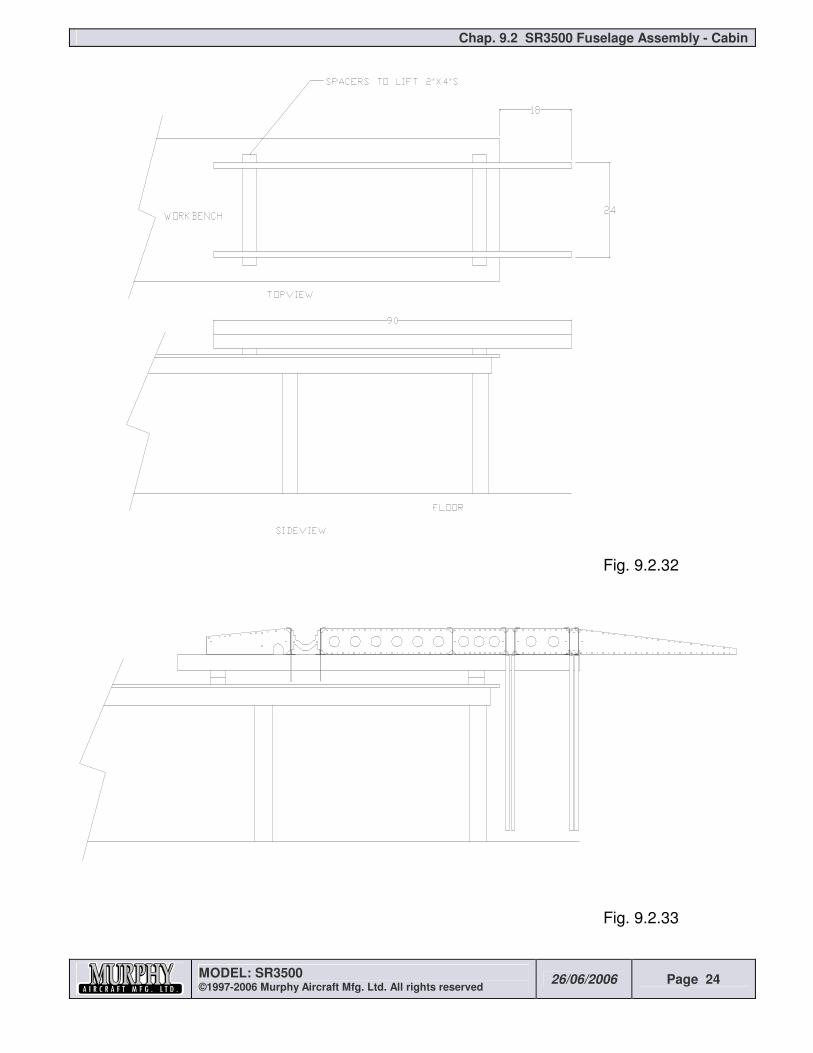
64) It is necessary to turn the floor assembly upside down on the workbench. If your workbench is less
than 32” in width, you will only need to raise the height of the workbench with 2” x 4”s so the
FUS0346 uprights clear the floor. If your workbench is over 32” wide, place 2” x 4” s so they
overhang one end 18”. Figure 9.2.32 and Figure 9.2.33.
Chap. 9.2 SR3500 Fuselage Assembly - Cabin
MODEL: SR3500 ©1997-2006 Murphy Aircraft Mfg. Ltd. All rights reserved
26/06/2006 Page 24
Fig. 9.2.32
Fig. 9.2.33
Chap. 9.2 SR3500 Fuselage Assembly - Cabin
MODEL: SR3500 ©1997-2006 Murphy Aircraft Mfg. Ltd. All rights reserved
26/06/2006 Page 25
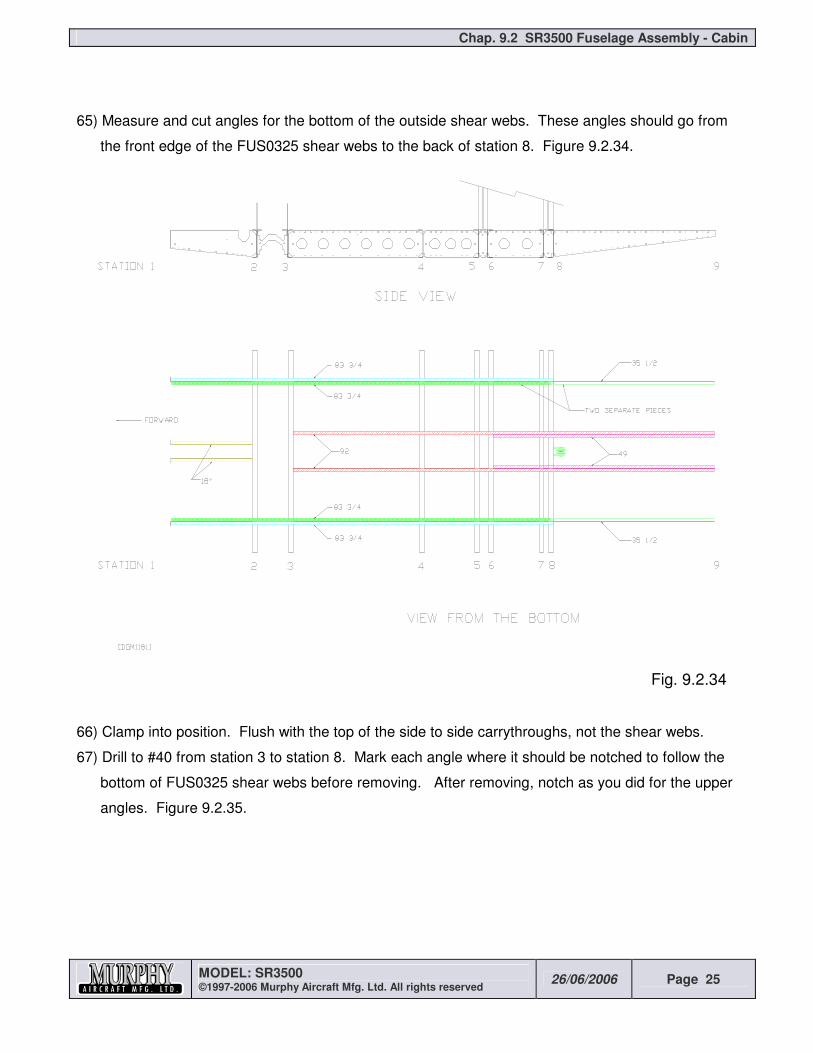
65) Measure and cut angles for the bottom of the outside shear webs. These angles should go from
the front edge of the FUS0325 shear webs to the back of station 8. Figure 9.2.34.
Fig. 9.2.34
66) Clamp into position. Flush with the top of the side to side carrythroughs, not the shear webs.
67) Drill to #40 from station 3 to station 8. Mark each angle where it should be notched to follow the
bottom of FUS0325 shear webs before removing. After removing, notch as you did for the upper
angles. Figure 9.2.35.

Chap. 9.2 SR3500 Fuselage Assembly - Cabin
MODEL: SR3500 ©1997-2006 Murphy Aircraft Mfg. Ltd. All rights reserved
26/06/2006 Page 26
Fig. 9.2.35
68) Replace the four angles and drill out to #30. Do not drill into the FUS0325 shear webs until the
firewall is installed later.
69) Measure and cut four angles for the bottom of the inside shear webs from station 6 to the end of
the FUS0315’s. Figure 9.2.34.
70) Drill only between stations 6 & 8 and notch just aft of station 8 as you did for the front of the outside
shear web angles. Aft of station 8 drill only a couple of holes to hold the angle. Final position will
be determined when the tail cone is installed.
71) Assemble bottom side stringers as Figure 9.2.34.
(Note: Figure 9.2.36 omitted by manual update)
72) Drill to #40 then #30 and cleco in place.
73) Remove each angle and debur, then replace and rivet together with 1/8” Avex rivets. Rivet angles
only from station 2 to station 8.
74) On the station 2 carrythrough bottom flange, drill a #40 hole as in Figure 9.2.37.
Chap. 9.2 SR3500 Fuselage Assembly - Cabin
MODEL: SR3500 ©1997-2006 Murphy Aircraft Mfg. Ltd. All rights reserved
26/06/2006 Page 27
Fig. 9.2.37
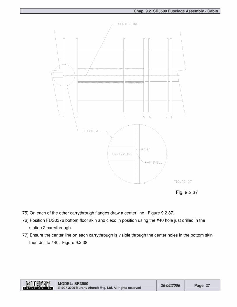
75) On each of the other carrythrough flanges draw a center line. Figure 9.2.37.
76) Position FUS0376 bottom floor skin and cleco in position using the #40 hole just drilled in the
station 2 carrythrough.
77) Ensure the center line on each carrythrough is visible through the center holes in the bottom skin
then drill to #40. Figure 9.2.38.

Chap. 9.2 SR3500 Fuselage Assembly - Cabin
MODEL: SR3500 ©1997-2006 Murphy Aircraft Mfg. Ltd. All rights reserved
26/06/2006 Page 28
Fig. 9.2.38
78) Ensure the assembly is square and level then drill out completely to #40 , then to #30, all but
perimeter holes, which should stay at #40.
79) Remove and debur.
80) Chromate, replace and rivet together with 1/8 Avex rivets. Do not rivet around the perimeter or
from station 6 back.
81) Carefully flip the assembly back over and place on level 2” x 4”s.
82) Draw a line down the outside flange of station 5 upright and draw a horizontal line 5/16” up on each
upright as in Figure 9.2.39.

Chap. 9.2 SR3500 Fuselage Assembly - Cabin
MODEL: SR3500 ©1997-2006 Murphy Aircraft Mfg. Ltd. All rights reserved
26/06/2006 Page 29
Fig. 9.2.39
83) Cleco a FUS0337 fuselage side skin into position using the key hole shown in Figure 9.2.40.
Fig. 9.2.40
84) At station 5 drill each #40 hole into the upright ensuring the holes are on the line drawn in step 82.
Chap. 9.2 SR3500 Fuselage Assembly - Cabin
MODEL: SR3500 ©1997-2006 Murphy Aircraft Mfg. Ltd. All rights reserved
26/06/2006 Page 30
85) Ensure station 8 upright is parallel to station 5 upright. Align station 8 keyholes with horizontal line
drawn in step 88 and drill to #40. Cleco.
86) Repeat step 85 for station 6 & 7 uprights.
87) Remove the side skin. On station 6, 7, and 8 uprights, draw vertical lines from the key holes just
drilled to the top of each upright. The lines should be parallel to the web of each upright.
88) Replace the side skin and drill the remaining holes. Start at the bottom and drill every 5th or 6th
hole. Cleco as you go. Go back and finish drilling all the #40 holes on the upright. Do not drill to
#30 at this time.
89) Repeat for the opposite side.
90) Remove the FUS0337 side skins.
(From step 91 to 96 is omitted by manual update)
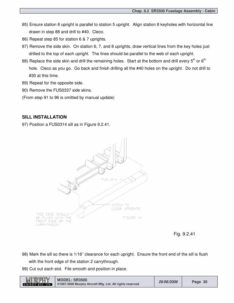
SILL INSTALLATION
97) Position a FUS0314 sill as in Figure 9.2.41.
Fig. 9.2.41
98) Mark the sill so there is 1/16” clearance for each upright. Ensure the front end of the sill is flush
with the front edge of the station 2 carrythrough.
99) Cut out each slot. File smooth and position in place.

Chap. 9.2 SR3500 Fuselage Assembly - Cabin
MODEL: SR3500 ©1997-2006 Murphy Aircraft Mfg. Ltd. All rights reserved
26/06/2006 Page 31
100) Clamp the top flange of the sill to the carrythrough flanges.
101) Using a long #30 drill, back drill through the carrythrough tabs into the sill. Start at the top and
cleco as you work down.
102) Drill downwards through the shear web angles with a long #40 drill.
103) Scribe the landing gear and float hard point slots on the sill.
104) On the inside of the sill draw a line flush with the backside of the station 4 carrythrough.
105) Remove the sill and cut out the landing gear and float hard point slots. Make sure the corners are
radiused.
NOTE: Steps 106 to 116 are for taildragger only.
106) Drill a STEP0004 (Step insert) as in Figure 9.2.42.
Fig. 9.2.42
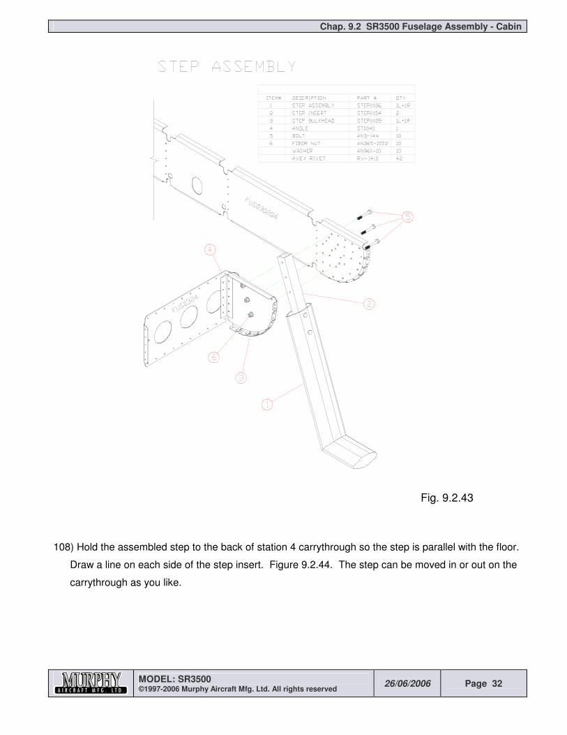
107) Position the step insert into the STEP0006 (Step assembly) drill and bolt together as in Figure
9.2.43.
Chap. 9.2 SR3500 Fuselage Assembly - Cabin
MODEL: SR3500 ©1997-2006 Murphy Aircraft Mfg. Ltd. All rights reserved
26/06/2006 Page 32
Fig. 9.2.43
108) Hold the assembled step to the back of station 4 carrythrough so the step is parallel with the floor.
Draw a line on each side of the step insert. Figure 9.2.44. The step can be moved in or out on the
carrythrough as you like.

Chap. 9.2 SR3500 Fuselage Assembly - Cabin
MODEL: SR3500 ©1997-2006 Murphy Aircraft Mfg. Ltd. All rights reserved
26/06/2006 Page 33
Fig. 9.2.44
109) Replace the sill and transfer the two lines to it.
110) Remove the sill and cut out a 1 1/8” x 1 1/8” square hole with rounded corners where the step will
go.
111) Replace the sill and insert the step. Back drill the #30 mounting holes into the station 4
carrythrough.
112) Remove the step and position a STEP0005 (Step bulkhead) back to back with the carrythrough
and back drill the #30 mounting holes.
113) Remove the sill. Cleco the step, step bulkhead and carrythrough together.
114) Drill out the mounting holes to #11.
115) Make a clip from ST0040 material to attach the step bulkhead to the shear web. Use five 1/8
avex rivets in each leg.
116) Rivet the bulkhead into place.
117) Replace the sill and drill out all holes going into the carrythroughs to #11. Drill out the shear web
angles to #30.
118) Rivet the sill in place with 1/8 & 3/16 avex rivets. Do not install rivets in stations 2 & 8
carrythroughs.
119) Do not bolt the steps in place until after the landing gear is on.

Chap. 9.2 SR3500 Fuselage Assembly - Cabin
MODEL: SR3500 ©1997-2006 Murphy Aircraft Mfg. Ltd. All rights reserved
26/06/2006 Page 34
CAGE ASSEMBLY
1) Cleco a FUS0305 inside post skin and a FUS0333 outside post skin together and drill a ¼” hole as
in Figure 9.2.45. This hole will be used to mount a control pulley later.
Fig. 9.2.45
2) Repeat for other two post skins.
3) Cleco four FUS0335 post spacers to a FUS0305 inside post skin as in Figure 9.2.46.
Fig. 9.2.46

Chap. 9.2 SR3500 Fuselage Assembly - Cabin
MODEL: SR3500 ©1997-2006 Murphy Aircraft Mfg. Ltd. All rights reserved
26/06/2006 Page 35
4) Position a FUS0300 channel on the post skin as in Figure 9.2.47.
Fig. 9.2.47
5) With a long #40 drill back drill the channel through the end flanges of the post spacers. Make sure
the post spacers are vertical.
6) Remove and trim the top end.
7) Repeat for the front channel but notch and bend the channel before trimming. Figure 9.2.48.

Chap. 9.2 SR3500 Fuselage Assembly - Cabin
MODEL: SR3500 ©1997-2006 Murphy Aircraft Mfg. Ltd. All rights reserved
26/06/2006 Page 36
Fig. 9.2.48
8) Cleco the assembly back together and using the post skin as a drill guide, drill the channel to #40.
9) Repeat for the opposite post. Make sure you build one left and one right.
10) Cleco a FUS0333 outside post skin to one assembly and drill to #40 and cleco.
11) Repeat for the other post.
12) Drill out the two end holes in the FUS0306 top carrythrough to ½”. Use a drill press and ream if
you can. Figure 5.
13) Drill (ream) out the four FUS0311 corner gussets to ½”. Figure 9.2.49.

Chap. 9.2 SR3500 Fuselage Assembly - Cabin
MODEL: SR3500 ©1997-2006 Murphy Aircraft Mfg. Ltd. All rights reserved
26/06/2006 Page 37
Fig. 9.2.49
14) Bolt the FUS0306 top carrythrough and four FUS0311 corner gussets together as in Figure 9.2.50.
Fig. 9.2.50
15) Position the top edges of the gussets parallel with the top surface of the carrythrough. This will
ensure the vertical legs will be 90º to the carrythrough. Using the gussets as drill guides, drill out
the carrythrough to #30. Use lots of clecos.
16) Center a post assembly between two corner gussets. Use a piece of .025” scrap to separate the
post and carrythrough. Drill to #30. Figure 9.2.51. Use lots of clecos.

Chap. 9.2 SR3500 Fuselage Assembly - Cabin
MODEL: SR3500 ©1997-2006 Murphy Aircraft Mfg. Ltd. All rights reserved
26/06/2006 Page 38
Fig. 9.2.51
17) Repeat for other side.
18) Position the cage assembly on the floor assembly. Use .040” spacers under the post assemblies.
These are needed so the floor skin will fit later. Figure 9.2.52.
Fig. 9.2.52
19) Back drill through the carrythroughs to #30 and then #11.
20) Back drill through the outer post skin into the sill to #30.

Chap. 9.2 SR3500 Fuselage Assembly - Cabin
MODEL: SR3500 ©1997-2006 Murphy Aircraft Mfg. Ltd. All rights reserved
26/06/2006 Page 39
21) Replace the FUS0337 side skins and backdrill into the sill.
22) Draw lines on the outside flanges of four RBULK0001 (Square bulkhead quarters). The lines
should go through the positioning holes.
23) Slide two RBULK0001’s into the top of the station 5 uprights. The other two into the station 8
uprights.
24) Cleco the positioning hole in the bulkheads to the 6th hole down at each station. Each bulkhead will
sit slightly higher than the side skin.
25) Mark the vertical leg of each bulkhead to have a 4” overlap with the uprights. Drill nine #30 holes in
the overlap.
26) Clamp the RBULKS together in the middle of the cabin area so the distance between the
positioning holes is 31”. Drill nine #30 holes in the overlap as you did when building the tail cone.
27) Drill the RBULK flanges using the side skins as drill guides.
28) Remove the RBULKS, trim to length, rivet together with Avex rivets.
29) Reinstall, and bend the upper flanges to be parallel with the top of the side skins. Figure 9.2.53.
Fig. 9.2.53
30) Shrink or crimp the top flange of the FUS0027L (Fuselage Root Rib) so it will lay flat. The flange
should be 90º to the side.
31) Trim the root rib as in figure 9.2.54.

Chap. 9.2 SR3500 Fuselage Assembly - Cabin
MODEL: SR3500 ©1997-2006 Murphy Aircraft Mfg. Ltd. All rights reserved
26/06/2006 Page 40
Fig. 9.2.54
32) Slide the root rib behind the FUS0333 outside post skin and FUS0337 side skin. Rest the front
part of the root rib on a .040” spacer on top of the carrythrough. The top flange of the root rib at
the rear should rest on the station 5 bulkhead. The door jams should be parallel. Figure 9.2.55.
Fig. 9.2.55
33) Back drill through the post skin and side skin into the root rib.
34) Repeat for the other side.
35) On the outside of each root rib draw two vertical lines as in Figure 9.2.56.

Chap. 9.2 SR3500 Fuselage Assembly - Cabin
MODEL: SR3500 ©1997-2006 Murphy Aircraft Mfg. Ltd. All rights reserved
26/06/2006 Page 41
Fig. 9.2.56
36) At the top of each line, drill a #40 hole. Figure 9.2.56.
37) Build up two RBULK0001 assemblies to fit on the lines between the root ribs. The flanges on the
froward RBULK assembly should face forward. Figure 9.2.57.
Fig. 9.2.57
38) Drill the top hole into the RBULK. Through the positioning hole in the RBULK drill a second hole.
Evenly space seven more holes from the bottom to the top. Do not put rivets in the top five holes of
the root rib center bulkhead at this time. They will be installed in the control section.
39) Drill and rivet the typical nine holes at the center overlap.

Chap. 9.2 SR3500 Fuselage Assembly - Cabin
MODEL: SR3500 ©1997-2006 Murphy Aircraft Mfg. Ltd. All rights reserved
26/06/2006 Page 42
40) Make four clips from ST0040 angle to tie the RBULK legs to the root rib channel. Use three 1/8”
Avex rivets in each leg. You may want to use countersunk rivets in the root rib channel for a better
appearance.
41) Make two clips from ST0040 angle to tie the root rib channel to the vertical post at station 3. Use
two of the holes in the corner gusset and 3/16” Avex rivets. Make sure the bottom channel of the
root rib is level side to side.
42) Cut two angles from FUS0035 (Stock material) to fit between station 5 and 8 bulkheads. They
should fit on the inside of the flanges. Figure 9.2.58.
Fig. 9.2.58
43) Position the angles and drill back through the prepunched holes in the side skin. Rivet with 1/8”
Avex rivets.
44) Center the FUS0028 (Cabin top) over the assembly. The top is wider than the fuselage and will be
trimmed later. Tuck the front flange of the cabin top under the front carrythrough corner gussets.
Figure 9.2.59.

Chap. 9.2 SR3500 Fuselage Assembly - Cabin
MODEL: SR3500 ©1997-2006 Murphy Aircraft Mfg. Ltd. All rights reserved
26/06/2006 Page 43
Fig. 9.2.59
45) Drill back through the corner gussets into the cabin top. Cleco.
46) Hold the cabin top down securely with 2”x 4” or tape.
47) Back Drill the cabin top through the positioning holes in each RBULK. Ensure the RBULK legs are
straight.
48) On the outer surface of the cabin top lay out and drill to #30 a nominal hole spacing of 1” between
positioning holes. Work from the center out and use lots of clecos. NOTE: At station 8 drill only
the two positioning holes.
49) With the same spacing, drill from the positioning holes to the sides. Do not drill at station 8.
50) Drill #30 holes through the cabin top and carrythrough with a nominal 1 ¼” spacing. Figure 9.2.60.
Fig. 9.2.60

Chap. 9.2 SR3500 Fuselage Assembly - Cabin
MODEL: SR3500 ©1997-2006 Murphy Aircraft Mfg. Ltd. All rights reserved
26/06/2006 Page 44
51) Drill a 1” nominally spaced row of #30 holes in the cabin top, root rib and angles.
52) Drill out the FUS0311 corner gussets to #11.


![I-400 Japan's Secret Aircraft-Carrying Strike Submarine [Hikoki 2006]](https://img.pdfslide.us/doc/110x75/55721313497959fc0b918beb/i-400-japans-secret-aircraft-carrying-strike-submarine-hikoki-2006.jpg)


