Embed Size (px)
Citation preview

Model Specifi cationsDigital expansion modules / Power supply for expansion modules / Thumbwheel switch input module
n Digital expansion modules
FBs-8EA(T,S)
FBs-8EX
FBs-8EY(T,S)
FBs-24EX FBs-24EYT
FBs-16EY(T,S)
FBs-20EX
FBs-16EA(T,S)
FBs-24EA(T,S) FBs-40EA(T,S)
FBs-60EA(T,S)
n Power supply for expansion modules
(7.62 mm terminal block)
n Thumbwheel switch input module
(30 pins header with latch)
25
(7.62 mm terminal block)
FBs-EPOW FBs-EPOW-D
FBs-32DGI
Specifi cation
Modelnumber
Digital input Digital output
Wiringmachanism
Dim
ension
24VDC Transistor (5 ~ 30VDC) Relay Thyristor
Low speed4.7mS
Low speed 200HzAC/DC
(2A)AC(1A)(0.5A)
High density(0.1A)
FBs-8EA
4 points
4 points
7.62 mmpitch
terminalblock
Figure 4
FBs-8EAT 4 points
FBs-8EAS 4 points
FBs-8EX 8 points
FBs-8EY 8 points
FBs-8EYT 8 points
FBs-8EYS 8 points
FBs-16EA
8 points
8 points
Figure 3
FBs-16EAT 8 points
FBs-16EAS 8 points
FBs-20EX 20 points
FBs-16EY 16 points
FBs-16EYT 16 points
FBs-16EYS 16 points
FBs-24EX 24 points 30 pinsheader
with latch
Figure 4FBs-24EYT 24 points
FBs-24EA14 points
10 points
7.62 mmpitch
terminalblock
Figure 1FBs-24EAT 10 points
FBs-24EAS 10 points
FBs-40EA24 points
16 points
Figure 1FBs-40EAT 16 points
FBs-40EAS 16 points
FBs-60EA36 points
24 points
Figure 1FBs-60EAT 24 points
FBs-60EAS 24 points
: Transistor output type: Blank—SINK output (NPN), J—SRCE output (PNP)
Specifi cation
Modelnumber
Power input
Residual capacity of output power Dim
ension
5VDC(Logic circuit)
24VDC(Input circuit)
24VDC(Output circuit)
FBs-EPOW 100 ~ 240VAC-15%/+10%, 21W 400mA 250mA 250mA
Figure 4FBs-EPOW-D 24VDC-15%/+20%, 12W 400mA 400mA* 250mA
Specifi cation
Modelnumber
Input method Occupied IR number Refresh time for input
Dim
ension
FBs-32DGI 16-bit (4 digits) x 8multiplexing input scan
8 words(32 digits/128 individual points)
10mS max.(IO ASIC)
Figure 4
* Directly from input power, but limited by specifi cations of circuit and fuses, with capacity of 400mA

Model Specifications7/16-segment LED display modules / Analog input (AI) module /
Analog output (AO) modules / Analog input/output (AI/O) module
FBs-7SG2
n 7/16-segment LED display modules
(16 pins box header)
FBs-7SG1
n Analog input (AI) module (7.62 mm terminal block)
FBs-6AD
n Analog output (AO) modules
(7.62 mm terminal block)
FBs-2DA FBs-4DA
n Analog input/output (AI/O) module
(7.62 mm terminal block)
FBs-4A2D
26
Module number Specification FB-7SG1 FB-7SG2
Display mode
Decoding display 4 bits to represent a character. It can display 16 kinds of pre-decoded character including 0 ~ 9, –, H, E, c, t and all blank
Non-decoding display Each segment controlled by 1 individual bit
Display number of character or points of LED
8 (4*) characters or 64 points individual LED
16 (8*) characters or 128 points individual LED
Refresh time for display 10mS max. (IO ASIC)
LED driving specification
Driving current 40mA /segmentDisplay method 1 ~ 8 characters multiplexing display
Driving voltage
Low voltage 5VDC (can be 10% up)High voltage 7.5V, 10V, 12.5V selectable (can be 10% up)
Fine tune of voltage drop 0.6V, 1.2V, 1.8V selectable
Over voltage driving indication Each channel has individual over voltage (O.V.) driving LED indication
Wiring method 16 pins flat cable,2.54mm header connectorIsolation method Photocouple isolation
Power input 24VDC –15%/+20%,static consumption is 2VA max, dynamic current is increased according to display.
Dimensions Figure 4* : For 16-segment alphanumeric character
Item Specification Voltage input Current input
Number of input point 6 points / 12-bitDigital input value -2048 ~ +2047 or 0 ~ 4095
Input signal range
Bipolar -10 ~ 10V or -5 ~ 5V -20 ~ 20mA or -10 ~ 10mAUnipolar 0 ~ 10V or 0 ~ 5V 0 ~ 20mA or 0 ~ 10mA
Maximum resolution 1.22mV (5V/4096) 2.44mA (10mA/4096)Accuracy ±1%Conversion time Conversion once for each scanMaximum input signal ±15V ±30mAInput impedance 63.2KΩ 250ΩIsolation method Transformer (Power) and photocouple (signal) isolation Power input 24VDC –15%/+20%, 2VA max.Dimensions Figure 4
Module number Specification FBs-2DA FBs-4DA
Number of output point 2 points / 14-bit 4 points / 14-bitDigital output value -8192 ~ +8191 or 0 ~ 16383
Output signal range
Bipolar Voltage : -10 ~ 10V or -5 ~ 5V , Current : -20 ~ 20mA or -10 ~ 10mAUnipolar Voltage : 0 ~ 10V or 0 ~ 5V , Current : 0 ~ 20mA or 0 ~ 10mA
Maximum Resolution Voltage : 0.3mV (5V/16384) , Current : 0.61mA (10mA/16384)Accuracy ±1%Conversion time Conversion once for each scan
Maximum allowable loading Voltage : 500Ω ~ 1 MΩ : Current : 0Ω ~ 500Ω
Isolation method Transformer (Power) and photocouple (signal) isolationPower input 24VDC –15/+20%, 2VA maxDimensions Figure 4
Item SpecificationNumber of input/output point 4 points AI / 12-bit + 2 points AO / 14-bit
Analog input specification Same as FBs-6AD
Analog output specification Same as FBs-2DA / 4DA
Dimensions Figure 4
Model Specifi cationsThermocouple modules / RTD modules / FB-DAP simple human-machine interfaces / RFID cards
FBs-TC6
n Thermocouple modules (7.62mm terminal block)
FBs-TC16
FBs-TC2 FBs-TC6 FBs-TC16
Number of input points 2 points 2 points 2 points
Thermocouple type and temperature measurement range
J ( -200~1200°C) E (-190~1000°C)K ( -190~1300°C) T (-190~380°C )R ( 0~1800°C ) B ( 350~1800°C)S ( 0~1700°C ) N (-200~1000°C)
Temperature compensation Built-in cold junction compensation
Resolution 0.1°C
Temperature refresh time 2/4 secondsOverall Precision ± (1%+1°C)
Isolation methodTransformer (power) and photocouple (signal) isolation (per-channel
isolation) Power input 24VDC -15%/+20%,2VA max.Dimensions Figure 4 Figure1
FBs-RTD6
n RTD modules (7.62mm terminal block)
FBs-RTD16
FBs-RTD6 FBs-RTD16
Number of input points 6 points 16 points
RTD type and temperature measurement range
3-wire RTD sensor (JIS or DIN)Pt-100(-200°C~850°C) Pt-1000((-200°C~600°C)
Resolution 0.1°C
Temperature refresh time 2/4 seconds
Overall Precision ± 1%
Isolation method Transformer (power) and photocouple (signal) isolation (no isolation between channels)
Power input 24VDC -15%/+20%,2VA max.
Dimensions Figure 4 Figure1
FB-DAP-B(R)
n FB-DAP simple human-machine interfaces
FB-DAP-C(R)
FB-DAP-B(R) FB-DAP-C(R)
Display 16-character × 2, 5×7dot matrix LCD display, with LED backlighting
Key pads 20 (4×5) membrane
Power input 24V,41mA (48mA) 5V,100mA (120mA)
Communication
Interface
Electric RS485 RS232
Mechanism3 pins European detachable terminal
blockD-sub 9 pins male connector
Number of linked station
Max. 16 stations 1
General features Timer, counter, register, relay, access of contact in PLC
Special features Alarm, information display, user defi nable special quick keys
Card reading feature Available only in -BR/-CR models, with maximum distance of 12 ~ 18 cm
Card writing feature Read/Write-able CARD-2 card, specifi ed models(-BW/-CW) only
Dimensions Figure 7
CARD-1 CARD-2
n RFID cardsCARD-1 CARD-2
Memory 64-bit + CRC error detecting codes
Working temperature -25~ 50 (ISO 7810)
Writing times Read-only At least 10000 times
Dimensions (mm) 86×54×1.3
Weight (g) 12
Specifi cationModel number
Specifi cationModel number
FBs-TC2
27
Specifi cation
Model number
Specifi cationModel number
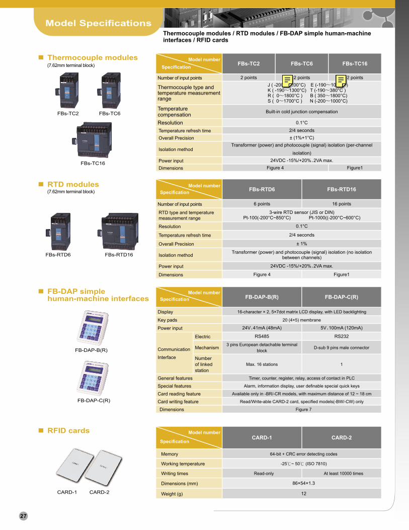
Peripheral SpecificationsMemory pack / Communication modules (CM) / Communication boards (CB)
FBs-PACK
n Memory pack Item Specification
Memory 1M bits FLASH ROM
Memory capacity 20K words program + 20K words data
Write protection DIP switch ON/OFF protection
n Communication modules (CM)
FBs-CM22
FBs-CM25E
FBs-CM5R FBs-CM5H
FBs-CM55E FBs-CM25C
FBs-CM55
FBs-CM25
Model/Item Specification Dimemsion
FBs-CM22 2 RS232 ports (Port3+Port4) with TX, RX indicators
Figure 5
FBs-CM55 2 RS485 ports (Port3+Port4) with TX, RX indicators
FBs-CM25 1 RS232 (Port3) + 1 RS485 (Port4) with TX, RX indicators
FBs-CM25E 1 RS232 (Port3) + 1 RS485 (Port4)with Ethernet interface and RUN,LINK,TX, RX indicators
FBs-CM55E 2 RS485 ports (Port3+Port4) with Ethernet interface and RUN,LINK,TX, RX indicators
FBs-CM25C General purpose optical isolation RS232↔RS485 converter, with RX indicators
FBs-CM5R General purpose optical isolation RS485 repeater, with RX indicators
FBs-CM5H General purpose optical isolation four ports RS485 Hub, with ACT, COLLISION indicators Figure 4
RS232Specification
Mechanism DB-9F standard plug
Electric EIA RS232 standard specifications
RS485Specification
Mechanism 3-pin European plug-able terminal block
Electric EIA RS485 standard specifications with built-in termination resistor
EthernetSpecification
Mechanism 4-pin European plug-able terminal block
Electric 10BaseT,IEEE 802.3 standard
n Communication boards (CB)
FBs-CB2
FBs-CB5 FBs-CB55
FBs-CB22
FBs-CB25
Model/Item Specification
FBs-CB2 1 RS232 port (Port2), with TX, RX indicators
FBs-CB22 2 RS232 ports (Port1+Port2), both with TX, RX indicators
FBs-CB5 1 RS485 port (Port2), with TX, RX indicators
FBs-CB55 2 RS485 ports (Port1+Port2), both with TX, RX indicators
FBs-CB25 1 RS232 port (Port1) +1 RS485 port (Port2), both with TX, RX indicators
FBs-CBE 1 Ethernet 10BaseT interface with LINK, RX and TX indicators
RS232Specification
Mechanism DB-9F standard plug
Electric EIA RS232 standard specifications
RS485Specification
Mechanism 3-pin European plug-able terminal block
Electric EIA RS485 standard specifications with built-in termination resistor
FBs-CBE
28
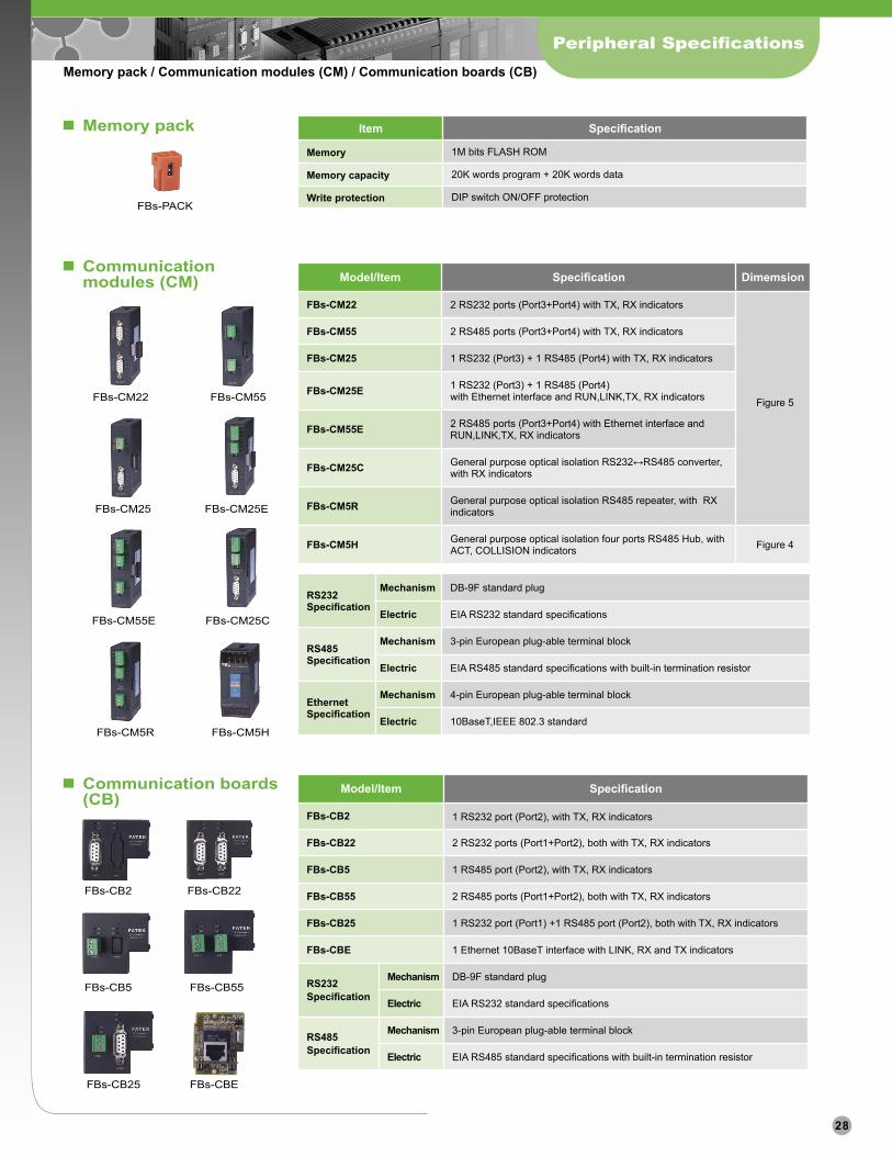
Peripheral Specifi cations
Other Accessories
n Other Accessories
Model Description
FBs-XTNR Converter box for extension of I/O expansion cables
LED.56R .56〞high-brightness, red color 7-segment LED display
LED.8R .8〞high-brightness, red color 7-segment LED display
LED2.3R 2.3〞high-brightness, red color 7-segment LED display
LED4.0R 4.0〞high-brightness, red color 7-segment LED display
LEDAN.8R .8〞high-brightness, red color 16-segment LED display
LEDAN2.3R 2.3〞high-brightness, red color 16-segment LED display
DB.56 (DB.56LEDR) .56〞7-segment 8 digits LED display PCB (DB.56LEDR with LED installed )
DB.8 (DB.8LEDR) .8〞7-segment 8 digits LED display PCB (DB.8LEDR with LED installed )
DB2.3 (DB2.3LEDR) 2.3〞7-segment 8 digits LED display PCB (DB2.3LEDR with LED installed )
DB4.0 (DB4.0LEDR) 4.0〞7-segment 4 digits LED display PCB (DB4.0LEDR with LED installed )
DBAN.8 (DBAN.8LEDR) .8〞16-segment 4 digits LED display PCB (DBAN.8LEDR with LED installed)
DBAN2.3 (DBAN2.3LEDR) 2.3〞16-segment 4 digits LED display PCB (DBAN2.3LEDR with LED installed)
FBs-232P0-9F-150 Dedicated communication cable for FBs main unit port0(RS232) to 9pin D-sub female connector, 150cm long
FBs-232P0-9M-400 Dedicated communication cable for FBs main unit port0(RS232) to 9pin D-sub male connector, 400cm long
FBs-USBP0-180 Communication cable for FBs main unit port0 (USB) (commercial USB A←→B cable), 180cm long
HD30-22AWG-200 22AWG I/O cable with 30pins socket, 200cm long (for FBs-24EX, 24EYT and 32DGI)
FBs-USBP0-180 HD30-22AWG-200FBs-232P0-9F-150 FBs-232P0-9M-400
FBs-XTNR LED.56R LED.8R LED2.3R LED4.0R
DB0.56LEDR DB.8LEDR DB2.3LEDR
DB4.0LEDR
LEDAN.8R LEDAN2.3R
DBAN.8LEDR DBAN2.3LEDR
29
Training Box
Item Description
Case Aluminum suitcase. Dimension is 46x32x16cm. Top cover and box body can be separated.
Power supply 100~240VAC / 2A fuse / power switch with indicator
PLC FBs-24MCT(transistor output)+FBs-CM25E(Ethernet communication module)
Programming tool
Programmer FP-07C handheld programming panel, can develop program, monitor (optional)
WinproladderProgrammingSoftware
Instructor site: Standard WinProladder with ' teaching assistant' utility
Student site: Standard WinProladder
Communicationinterface
Built-in Port0 RS232, Mini-Din connector
Communication board(CB)(optional)
Port1RS232 or RS485 selectable, directly mounted on FBs-24MCT main unit
Port2
FBs-CM25E
Port3 RS232, standard DB-9F connector
Port4 RS485, 3-pin European terminal block
(Port4) Ethernet 10BaseT, IEEE 802.3 standard. Use port4 to interface PLC main unit
Input interface Banana terminal and simulation switch with automatic and manual reset functions
Output interface Banana terminal, 10 points. Transistor output(Y0~Y9). All outputs buffer with discrete relay before come to terminal. Y0 and Y1 also provide a direct output terminal for high-speed pulse output (HSPSO) application.
Expansion module (optional) Secured by DIN Rail, 12.5cm wide slot, can accommodate three 4cm thin modules or other modules with equivalent width
Application peripheral
Display module 4 digits 7-segment display module,attached with BCD decoding circuit
Thumbwheel switch 4 digits BCD thumbwheel switch module
Keyboard module 4 x 4 matrix keyboard module(Wiring coordinate with convenient instruction)
Encoder Power supply 24VDC、200P/R、open collector、A/B phase
Stepping motor CK/DIR control,200P/R
LED display 10 of 10mmØ high-brightness LED (in red, yellow, and green), driven individually by Y0 to Y9
Number of linked stations Maximum 254 stations (1 station for instructor, 253 stations for student)
30
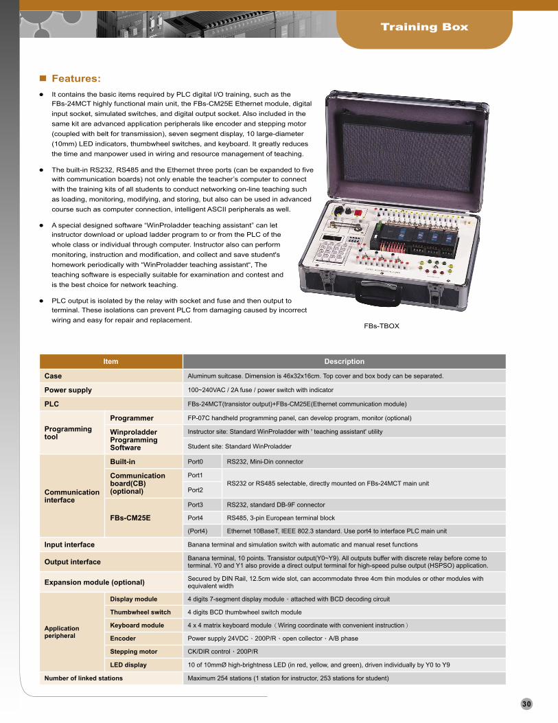
n Features: It contains the basic items required by PLC digital I/O training, such as the
FBs-24MCT highly functional main unit, the FBs-CM25E Ethernet module, digital input socket, simulated switches, and digital output socket. Also included in the same kit are advanced application peripherals like encoder and stepping motor (coupled with belt for transmission), seven segment display, 10 large-diameter (10mm) LED indicators, thumbwheel switches, and keyboard. It greatly reduces the time and manpower used in wiring and resource management of teaching.
The built-in RS232, RS485 and the Ethernet three ports (can be expanded to five with communication boards) not only enable the teacher’s computer to connect with the training kits of all students to conduct networking on-line teaching such as loading, monitoring, modifying, and storing, but also can be used in advanced course such as computer connection, intelligent ASCII peripherals as well.
A special designed software “WinProladder teaching assistant” can let instructor download or upload ladder program to or from the PLC of the whole class or individual through computer. Instructor also can perform monitoring, instruction and modification, and collect and save student's homework periodically with “WinProladder teaching assistant“, The teaching software is especially suitable for examination and contest and is the best choice for network teaching.
PLC output is isolated by the relay with socket and fuse and then output to terminal. These isolations can prevent PLC from damaging caused by incorrect wiring and easy for repair and replacement.
FBs-TBOX
Handheld Program Development Tool
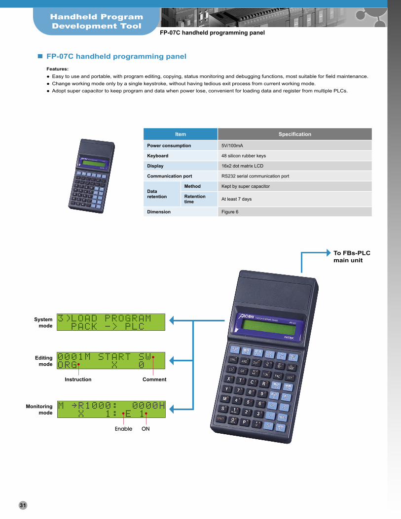
FP-07C handheld programming panel
n FP-07C handheld programming panelFeatures: Easy to use and portable, with program editing, copying, status monitoring and debugging functions, most suitable for field maintenance. Change working mode only by a single keystroke, without having tedious exit process from current working mode. Adopt super capacitor to keep program and data when power lose, convenient for loading data and register from multiple PLCs.
Item Specification
Power consumption 5V/100mA
Keyboard 48 silicon rubber keys
Display 16x2 dot matrix LCD
Communication port RS232 serial communication port
Data retention
Method Kept by super capacitor
Retention time At least 7 days
Dimension Figure 6
To FBs-PLC main unit
31

Dimensions
Figure 1
W
PROGRAMMABLECONTROLLER
2 - 4.5
Figure 2
Figure 4
Figure 6
Figure 5
Figure 7
Figure 3
W Module
90mm FBs-20M,FBs-24M,FBs-24EA(P)FBs-TC16,FBs-RTD16
130mm FBs-32M,FBs-40M,FBs-40EA(P)
175mm FBs-60M,FBs-60EA(P)
2 - 4.5
60
PROGRAMMABLECONTROLLER
FATEKFATEK
2 - 4.5
90
2 - 4.5
FATEK
20
2 - 4.5
32