Embed Size (px)
Citation preview
Source of Quality
MODEL SPEC-150 RADIOGRAPHY EXPOSURE DEVICEAND
ASSOCIATED EQUIPMENT
USERS MANUALRevision (10)
November 1 2011
Source Production amp Equipment Co Inc113 Teal Street
St Rose Louisiana 70087 USAwwwspec150com
i
TABLE OF CONTENTS
10 GENERAL INFORMATION11 Description12 Safety Analysis13 Quality Assurance14 G-60 Source Classification15 User Qualification Requirements16 Authorized Associated Equipment17 Safety Precautions18 Items Accompanying the Exposure Device19 Abbreviations110 Warranty and Limitation of Liability
20 DESCRIPTION21 SPEC-150 Exposure Device
211 Exposure Device Key212 Device and Component Drawings213 Labeling and Marking214 Materials of Construction
22 Control Assembly221 Control Assembly Lengths and Materials222 Control Assembly Operation223 Control Assembly Adaptor224 Control Assembly Drive Cable and Connector
23 Guide Tubes
30 GENERAL CONDITIONS OF USE31 Intended Use32 Environmental Conditions of Use33 Installation34 Basic Operation35 Occasions for Persons to be Near the Device36 Special Equipment Use
40 MECHANICAL SAFETY FEATURES OF THE DEVICE41 Exposure Device Lock42 Source Assembly Lock43 Automatic Securing Mechanism (ASM)44 ASMLock Module45 No Visual Source Position Indicator46 Source Assembly Misconnect Protection47 Lock Cap48 Safety Plug49 Error-Free Design
ii
410 Lubrication-Free Design411 Carrying Handle amp Tie-Down Holes412 Protection from Unauthorized Access
50 RADIATION SAFETY FEATURES51 External Radiation Levels52 Protection from Scattered Radiation53 Protection from DU Contamination
60 SPEC-150 SYSTEM OPERATING PROCEDURES61 Safety Precautions
611 Survey Instrument612 Personnel Training and Supervision613 Personnel Monitoring614 Protection from Direct Radiation615 Protection from Scattered Radiation
62 SPEC-150 Radiography System Set-Up Procedures63 SPEC-150 Radiography System Operation Procedures64 SPEC-150 Radiography System Break-Down Procedures65 Emergency Response Procedures
651 Equipment Malfunctions and Accidents652 Fire653 Lost or Stolen Source
70 SPEC-150 SAFETY INSPECTION PROCEDURES71 Daily Safety Inspection Procedure
711 Survey Instrument712 SPEC-150 Exposure Device713 Source Assembly Connector714 Control Assembly715 Pistol Grip Daily Inspection716 Drive Cable717 Drive Cable Connector718 Control Assembly Adaptor719 Guide Tube Daily Inspection
72 Quarterly Safety Inspection Procedures721 Survey Instrument722 SPEC-150 Exposure Device723 G-60 Source Assembly Connector724 Control Assembly725 Guide Tube Quarterly Inspection726 SPEC-150 System Operational Check
80 SPEC-150 MAINTENANCE AND REPAIR PROCEDURES81 General82 Recommended Replacement Components
-iii-
83 Modifying Repairing or Tampering with the Device84 SPEC-150 Exposure Device85 ASMLock Module
851 ASMLock Module Removal852 ASM Lock Module Installation
86 Outlet Panel Assembly861 Outlet Panel Assembly Replacement Procedures
87 Lock Cap Safety Plug Key and Control Adaptor88 Radiation Profile Survey Procedures89 G-60 Source Assembly810 Control Assembly Drive Cable Maintenance and Repair
8101 Control Assembly Disassembly8102 Control Assembly Internal Component Inspection8103 Control Assembly Cleaning Procedures8104 Drive Cable Maintenance and Cleaning Procedure8104 Control Re-assembly Procedure
811 Guide Tube
90 TRANSPORTATION PREPARATIONS91 Procedures for Preparing and Loading the Package
911 General Package Inspection912 Packaging913 Outer Package Surface Contamination914 Transportation Requirements915 Type B Quantity Consignee Notification
92 Procedures for Receipt and Unloading the Package921 Unloading the SPEC-150922 Receiving the SPEC-150
93 Preparation of an Empty Package for Transport
SPEC-150 Operating Manual Revision 10 Revised 110111 Page 1
10 GENERAL INFORMATION
11 Description
The SPEC-150 is a portable ANSI Type 1 depleted uranium shielded exposure device used forindustrial gamma radiography nondestructive testing applications The SPEC-150 radiographysystem consists of the SPEC-150 exposure device a model G-60 source assembly and associatedequipment This equipment includes a manual remote control assembly guide tube andcollimator The G-60 is an Iridium-192 radioactive sealed source with a maximum activity of150 curies (5550 GBq) The control assembly is used to move the source out of the exposuredevice and into the guide tube to perform radiography The collimator provides radiationshielding at the end of the guide tube
12 Safety Analysis
The model SPEC-150 exposure device model G-60 source and associated equipment meet therequirements specified in ANSI N432-1980 Radiological Safety for the Design andConstruction of Apparatus for Gamma Radiography and 10 CFR Part 3420 PerformanceRequirements for Radiography Equipment The SPEC-150 System is approved by theLouisiana Radiation Protection Division and the United States Nuclear Regulatory Commission(certificate number USA9263B(U)-96) A Registry Sheet is available upon request
13 Quality Assurance
The SPEC-150 exposure device is manufactured under the control of the SPEC QualityAssurance Program SPEC has been issued Quality Assurance Program Approval forRadioactive Material Packages Number 0102 by the US Nuclear Regulatory Commission TheQuality Assurance Program controls the design fabrication assembly testing use maintenanceand repair of radioactive material packages exposure devices sources and associated equipment
14 G-60 Source Classification
The model G-60 source meets ANSI N542 classification 77C43515 The source meets USDepartment of Transportation 10 CFR Part 34 49 CFR and International Atomic EnergyAgency (IAEA) requirements for Special Form Radioactive Material It is authorized fortransport under IAEA Certificate of Competent Authority for Special Form RadioactiveMaterials Certificate Number USA0608S The G-60 source is approved by the LouisianaRadiation Protection Division A Registry Sheet is available upon request
15 User Qualification Requirements
Users are required to be specifically licensed by the Nuclear Regulatory Commission or anAgreement State to use the SPEC-150 in the United States National regulations may apply inother countries Radiography workers must be formally trained and qualified in the safe use ofthe SPEC-150 system survey instruments and general radiation safety They must bespecifically authorized by the licensee to use the SPEC-150 The SPEC-150 must be used in
SPEC-150 Operating Manual Revision 10 Revised 110111 Page 2
strict compliance with licensee Operating and Emergency Procedures applicable safetyregulations and all operation inspection and maintenance instructions in this manual
16 Authorized Associated Equipment
The SPEC-150 is authorized for use with approved control assemblies flexible Yellow guidetubes rigid J tubes and collimators that are designed tested manufactured and inspected bySPEC in accordance with 10 CFR Part 3420 regulations Replacement sources and associatedequipment manufactured by other authorized manufacturing companies may be tested andsubmitted for approval for use with the SPEC-150 exposure device Licensees should consultwith the applicable NRC or Agreement State licensing agency to determine if specific authorityis required to use custom-made associated equipment such as extra length guide tubes or remoteunsecuring mechanism (RUM)
17 Safety Precautions
The SPEC-150 must be used only by authorized and monitored individuals who have beenformally trained in the use of this device the proper use of survey instruments and generalradiation safety This device must be used in strict compliance with licensee operating andemergency procedures and all applicable government safety regulations to assure that exposureto workers and the public is maintained AS LOW AS REASONABLY ACHIEVABLE(ALARA) below established dose limits
The SPEC-150 must be used with a calibrated and operable survey instrument at all times THEUSE OF OTHER DEVICES (SUCH AS ALARMING RATEMETERS BEEPERS SOURCEPOSITION INDICATORS AND AREA ALARMS) INSTEAD OF A SURVEYINSTRUMENT IS EXTREMELY DANGEROUS AND NEGLIGENT Trainees helpers andassistants must operate the device only under the direct visual surveillance of a qualifiedradiographer It is recommended that licensees provide workers with NRC publicationWorking Safely with Gamma Radiography NUREGBR-0024
18 Items Accompanying the Exposure Device
1 SPEC-150 Users Manual
2 Model 1 Leak Test Kit and instructions
3 Quality Assurance Final Inspection Certificate The certificate includes a radiationprofile report It records the highest radiation levels extrapolated to 150 curies at thesurface (not readings averaged over large areas) and at one meter from all six surfacesIt includes the radiation level at the outlet nipple when the safety plug is removed
4 Optional SPEC-150 Annual Maintenance Program information flier
5 6 ea White Tamper Resistant Seals
SPEC-150 Operating Manual Revision 10 Revised 110111 Page 3
18a ASMLock Module and Outlet Panel Assembly Replacement Tools
1 A set of special tools to remove the outlet panel assembly are provided with the newassembly
2 A set of special tools are loaned with each spare ASMLock Module purchased andwith each replacement ASMLock Module provided by SPEC under the conditions ofthe ASM Lock Module Maintenance Program
19 Abbreviations
ANSI American National Standards InstituteASM Automatic Securing MechanismISO International Organization for StandardizationIAEA International Atomic Energy AgencyDU Depleted UraniumSPEC Source Production amp Equipment Co IncTMJ SPEC Thermal Metal Joining Special Process
110 Warranty and Limitation of Liability
SPEC PRODUCT LIMITED WARRANTY1 Source Production amp Equipment Co Inc (SPEC) warrants that on the date the exposure device
or source changer is sold it will meet SPECrsquos standard specifications for exposure devices andsource changers will be free of defects in material and manufacture THIS WARRANTYAPPLIES ONLY AGAINST DEFECTS AND NONCONFORMITIES THAT AREDISCOVERED WITHIN ONE (1) YEAR FROM THE DATE OF FIRST SALE BY SPEC ORAN AUTHORIZED SPEC DEALER ALL SPEC MANUFACTURED SOURCEASSEMBLIES ASSOCIATED EQUIPMENT AND REPLACEMENT PARTS OFRADIOGRAPHY SYSTEMS (EG CONTROL ASSEMBLIES GUIDE TUBESASMLOCK MODULE UNITS CONTROL ADAPTORS ETC) AND ALL OTHER SPECMANUFACTURED PRODUCTS ARE WARRANTED TO BE FREE OF DEFECTS ANDNONCONFORMITIES FOR A PERIOD OF THIRTY (30) DAYS FROM THE DATE OFFIRST SALE If the Buyer discovers the defects or nonconformities Buyer must notify SPECin writing certified and post marked within thirty (30) days after the date of discovery and inno event later than thirteen (13) months after the date of first sale for exposure devices and sixty(60) days for associated equipment to Attn Sales Manager 113 Teal Street St Rose LA70087
SECTION OF LAW AND FORUM2 The Buyer and SPEC hereby specifically agree that this sale shall be deemed consummated in
the State of Louisiana SPEC and Buyer hereby agree that the laws for the State of Louisianawill apply to this agreement in its interpretation and enforceability In addition SPEC andbuyer agree that any controversy andor litigation concerning the purchase of SPECrsquos productby Buyer shall be held and filed in a court of competent jurisdiction within the Parish ofJefferson State of Louisiana
SPEC-150 Operating Manual Revision 10 Revised 110111 Page 4
DISCLAIMER OF WARRANTIES3 Any Warranties of the product herein sold are only those provided by SPEC SPEC hereby
expressly disclaims all warranties except those warranties which have been provided in theabove section entitled ldquoSPEC Product Limited Warrantyrdquo SPEC hereby expressly disclaimsall or any other express or implied warranties including any implied warranty ofmerchantability or fitness for a particular purpose SPEC neither assumes nor authorizes anyother person to assume for it any liability in connection with the sale of its product
It is specifically understood between the buyer and SPEC that this sale is made without anywarranty not included within SPECrsquos express warranties (as provided above) except as to titleThe buyer herein specifically waives the implied warranties provided for by Louisiana law andany other state law (should a court of competent jurisdiction not honor the parties selection ofLouisiana law to govern its relations) including all warranties against vices or defects for anyparticular purpose This express waiver shall be considered a material and integral part of thissale There are no exceptions to the foregoing provision except as maybe expressed in writingby SPEC
BUYERrsquoS REMEDIES4 If the exposure device fails to conform to the warranties in paragraph 1 and such nonconformity
is not due to misuse or improper maintenance Buyer shall notify SPEC as provided inparagraph 1 and within a reasonable time SPEC shall provide at its option one of thefollowing1) repair or replacement of any nonconforming or defective parts or 2) full refund of the purchase price or reduced refund based on age and use of equipment THIS REMEDY SHALL BE THE EXCLUSIVE AND SOLE REMEDY OF BUYER FORANY BREACH OF WARRANTY
5 Should any provision aspect or term of this waiver of warranties be deemed unenforceable forany reasons it is specifically agreed by SPEC andor its product distributors and the buyer thatthe aspect provision andor term found unenforceable shall be severed from the agreement asa whole so the most limited extent necessary All other aspects terms and provisions shallmaintain their full force and effect
EXCLUSION OF CONSEQUENTIAL AND INCIDENTAL DAMAGES6 IN NO EVENT SHALL SPEC BE LIABLE FOR ANY INCIDENTAL SPECIAL INDIRECT
OR CONSEQUENTIAL DAMAGES WHETHER RESULTING FROM NONDELIVERY ORFROM THE USE MISUSE OR INABILITY TO USE THE PRODUCT OR FROM DEFECTSIN THE PRODUCT OR FROM SPECrsquoS OWN NEGLIGENCE OR OTHER TORT Thisexclusion applies regardless of whether such damages are sought for breach of warranty breachof contract negligence or strict liability in tort or under any other legal theory
EXCLUSION OF LIABILITIES7 The purchaser of SPECrsquos product by purchasing the product attests to SPEC its distributors
and all other third parties that it is a knowledgeable experienced and a sophisticated user of saidproduct Buyer hereby warrants that it fully understands the dangerous nature of the radioactivematerial together with the safety and regulatory requirements attendant to its use Buyer hereby
SPEC-150 Operating Manual Revision 10 Revised 110111 Page 5
warrants that it will use and maintain the purchased product in a manner which does not violateNuclear Regulatory Commission or equivalent Agreement State license conditions andregulations imposed upon the licensee or worker regarding the safe use of the equipment
8 The foregoing warranties and liabilities of SPEC and remedies of Buyer are exclusive andBuyer waives and releases all other warranties obligations and liabilities of SPEC and all otherremedies claims and rights of Buyer relating in any way to the equipment covered by thisagreement whether arising from contract warranty or tort or from negligence tort or otherfault of SPEC including claims for loss of or damage to the equipment SPEC assumes noliability or responsibility for any damages or injuries regardless of cause resulting from the useof SPEC manufactured equipment or resulting from the use of any radioactive material orassociated equipment in a manner that violates Nuclear Regulatory Commission or equivalentAgreement State license conditions and regulations imposed on the licensee or worker regardingthe safe use of the equipment
9 This warranty shall not apply to products or parts which have been subjected to misuseimproper installation unauthorized repairs or modifications neglect or accident conditionsThe warranty is void if equipment is not operated and maintained in accordance withinstructions provided in SPEC userrsquos manuals The customer is responsible for returningproducts to SPEC freight prepaid and for preparing the product for shipment in accordancewith applicable transport laws and regulations
20 DESCRIPTION
21 SPEC-150 Exposure Device
The device consists of a depleted uranium shield inside a welded titanium housing measuringapproximately 141 cm (5-916 inches) high 136 cm (5-38 inches) wide and 368 cm (14-12inches) long The DU shield includes a curved S-tube that the source travels through Thesecuring and locking mechanisms are installed at one end of the device and an outlet port (outletnipple) is installed at the other end The device weighs a maximum of 535 pounds
211 Exposure Device Key
The device key is attached to the control assembly by a short stainless steel chain toprevent loss of the key When the controls are not in use the key is installed in the openend of the adaptor to serve as a dust cap to protect against ingress of foreign material intothe control assembly As an option the key may be removed from the control assemblyand replaced with a conventional dust cover
212 Device and Component Drawings
Drawings of the SPEC-150 Exposure Device ASMLock Module Safety Plug OutletPanel Assembly Lock Cap Control Assembly Adaptor and G-60 Source Assembly arein the appendix to this manual
SPEC-150 Operating Manual Revision 10 Revised 110111 Page 6
WARNING - DANGER
Radiation may cause radiation burns sickness cancer genetic defects and death This devicemay be used only by authorized and monitored individuals who have been formally trained in theuse of this device the proper use of survey instruments and radiation safety This device mustbe used in strict compliance with operating and emergency procedures and applicable regulationsIt must be used with a calibrated survey instrument at all times Trainees helpers and assistantsmust work under the direct surveillance of a radiographer
213 Labeling and Marking
1 The exposure device nameplate is marked with SPECs name address devicemodel serial number curie capacity and radionuclide mass of depleted uraniumshielding and device weight
2 One caution label stating Caution - Radioactive Material - Do Not Handle - NotifyCivil Authorities if Found
3 The warning labels state
4 The source identification tag lists the isotope source model serial number activityand date of manufacture A tag is provided with each source
5 Licensees must apply their company name address and telephone number to theexterior of the exposure device to meet 10 CFR Part 3420 (b) (v) The labeling maybe painted directly on the device or a printed label may be attached by adhesivesDrilling riveting or welding is prohibited
214 Materials of Construction
The principal materials used in the SPEC-150 are a depleted uranium shield and a titaniumhousing and structure Stainless steel fittings bronze bushings epoxy potting compoundpolyurethane foam fill and rubber are non-structural materials of construction
22 Control Assembly
The control assembly commonly called a crank-out is a manually operated mechanicalapparatus used to move the source assembly from the exposure device to the exposed workingposition at the end of the guide tube and back into the exposure device from a safe distance
It consists of a pistol grip assembly two conduits (sheaths) typically 25 to 50 feet long aflexible metal drive cable with a connector to attach to the source assembly a drive cable stopand an adaptor to attach the control assembly to the exposure device The pistol grip consistsof an aluminum housing drive gear wear ring two bearings and crank handle
SPEC-150 Operating Manual Revision 10 Revised 110111 Page 7
221 Control Assembly Lengths and Materials
Control assemblies are available in a variety of conduit types and lengths Customdesigned or extra length control assemblies may require government authorizationConsult with SPEC or your licensing authority to verify
Max LengthControls with Yellow conduit 35 ftControls with Red conduit 40 ftControls with Blue conduit 50 ftControls with two types of conduit See Note 1
Note 1 The length of a control assembly made with two types of conduits (ieYellow and Silver) is limited by the maximum length specified for thetype of conduit installed on the drive (upper) side of the controlassembly pistol grip
222 Control Assembly Operation
The control assembly is typically operated by hand yet may be operated mechanically Thepistol grip cover plate is permanently marked with the words expose and retract andwith arrows to indicate the directions of cranking motion to expose or retract the sourceassembly Clockwise cranking is used to crank out and counterclockwise cranking is usedto retract
The typical amount of torque required to operate the system freely with a 25 foot controlassembly is approximately 1-14 foot pounds The maximum amount of torque should notexceed approximately 2 foot pounds when operated by hand If an automatic mechanicalapparatus is used to operate the control assembly the maximum amount of torque allowedto be applied to the drive gear is 4 foot pounds
223 Control Assembly Adaptor
The control assembly adaptor is used to attach the control assembly to the exposure deviceAfter the device is unlocked the spring-loaded operating lever on the adaptor is used tounlock the source assembly The adaptor may be used on any control assembly authorizedfor use with the SPEC-150
224 Control Assembly Drive Cable and Connector
The drive cable is a flexible wire steel cable with a connector at one end (to attach to thesource assembly) and a spiral stop spring at the other end (to prohibit accidental loss)The cable meshes with the gear inside the pistol grip and is moved as the control handleis rotated
SPEC-150 Operating Manual Revision 10 Revised 110111 Page 8
The drive cable connector is the SPEC Fail-Safe connector and is the same connector usedfor SPEC 2-T model G-1F and G-3F sources and other source models using the Fail-Safeconnector
23 Guide Tubes
Guide tubes are hollow flexible or rigid tubes with an end piece (exposure head) attached to theworking (exposure) end SPEC Yellow guide tube material designates yellow-colored PVCcovered 38 inch inside diameter flexible Type 302 stainless steel inner core material SPECRigid material designates Type 304 or 316 stainless steel 38 and 12 inch inside diameterseamless rigid tubing This material is used for J tubes and other specialized applicationsThe maximum standard length with extension(s) is 21 feet Longer and custom designed guidetubes might require government authorization Consult with SPEC or your licensing authorityto verify requirements
30 GENERAL CONDITIONS OF USE
31 Intended Use
The SPEC-150 exposure device is intended for industrial gamma radiography operations attemporary job site and permanent facilities in all industries and locations Typical industriesand locations are associated with oilfield petrochemical marine construction manufacturingand aerospace activities It is expected that the equipment will be used at offshore structuresmetal fabrication yards foundries chemical plants refineries shipyards building siteslaboratories and maintenance facilities
32 Environmental Conditions of Use
The SPEC-150 exposure device is designed to perform industrial radiography at field sites andpermanent facilities with a broad range of environmental conditions It will operate properlywithin a temperature range of -40 degrees F to +180 degrees F and in all levels of relativehumidity and moisture The device is resistant to corrosion from typical industrial andenvironmental atmospheres For use underwater the device must be installed in a protectiveenclosure or other precautions must be taken to prohibit damage to internal components due toslow corrosion Licensees should consult with the applicable government licensing agency todetermine if specific authority is required to use the SPEC-150 exposure device underwater
33 Installation
There are no installation requirements The device is not normally installed (attached) in apermanent manner If the device must be installed the user should develop the means to securethe device as needed for safety and security The eight tie-down holes at the top and bottomcorners of the device provide a means for the user to attach mechanical safety security andlifting attachments
34 Basic Operation
SPEC-150 Operating Manual Revision 10 Revised 110111 Page 9
In typical use a manual remote control assembly and guide tube are attached to the deviceduring set up of the SPEC-150 System The exposure device is unlocked with a key then thesource assembly is unlocked with the control adaptor operating lever Then before eachradiographic exposure the source assembly is unsecured from the automatic securingmechanism (ASM) by depressing the release plunger on the top of the device The controlassembly is used to move the source assembly out of the shielded position to the final workingposition at the end of the guide tube When the source assembly is retracted back into the fullyshielded position inside the device it is automatically secured by the ASM Finally a safetycheck must be performed with a survey instrument after each exposure
35 Occasions for Persons to be Near the Device
Only specifically trained authorized and monitored individuals are allowed to be near thedevice when it is in use Unauthorized individuals must be restricted by the user from closeproximity to the device to meet applicable radiation dose limit regulations It is expected thatunmonitored persons such as shipping transport and emergency response personnel will benear the device only after it has been properly prepared for transport
36 Special Equipment Use
If the SPEC-150 must be used in working positions that are difficult or dangerous for theworker to reach (for example when suspended off the ground or on a trolley inside a pipe) itis recommended that the licensee apply for authorization to use a remote unsecuringmechanism Contact SPEC for assistance
40 MECHANICAL SAFETY FEATURES OF THE DEVICE
41 Exposure Device Lock
The device lock is located at the bottom of the lock end plate It is operated by a durablecircular stainless steel key The safety features of the device lock are described below
1 The key cannot be intentionally removed nor inadvertently fall out when the device isunlocked
2 The key serves as a dust cover for the device lock and limits ingress of foreign materialwhen the device is in use The key may also be used as a dust cover for the controlassembly when it is not in use
3 The key must be removed to disconnect the control adaptor from the exposure deviceTherefore the key cannot be inadvertently left in the device when breaking down thesystem
4 The lock cannot be unlocked with a readily available substitute for the key
5 The lock cannot be removed from the ASMLock Module
SPEC-150 Operating Manual Revision 10 Revised 110111 Page 10
42 Source Assembly Lock
The source assembly lock is located at the center of the lock end plate It prohibits movementof the source assembly in both directions when engaged It is manually operated by use of theoperating lever on the control assembly adaptor The lever must be rotated toward the Unlockposition to disengage the source assembly lock The numerous safety features of the sourceassembly lock are described below
1 The source assembly lock cannot be operated with a readily available substitute for thecontrol assembly adaptor operating lever
2 The control assembly adaptor must be properly attached to the exposure device tooperate the source assembly lock
3 The source assembly lock cannot be disengaged unless the exposure device is unlocked
4 When the source assembly lock is engaged the release plunger cannot be engaged(latched down) Therefore the source assembly cannot be inadvertently unsecured
5 The source assembly lock can be conveniently engaged to provide an added measure ofsecurity during temporary interruptions in radiography operation
6 The exposure device cannot be locked when the source assembly lock is disengaged
7 In accordance with ANSI N432 Section 5124 the source assembly lockABSOLUTELY POSITIVELY cannot be engaged unless the source assembly has beenretracted to the fully secured position The user cannot inadvertently lock the sourceout
8 The control adaptor cannot be attached to the device if the drive cable connector has notbeen attached to the source assembly connector
43 Automatic Securing Mechanism (ASM)
The ASM automatically secures the source assembly when it is fully retracted into the deviceIt prevents movement of the source assembly toward the outlet end The source assembly mustbe unsecured from the ASM by depressing the release plunger located at the top of the devicebefore each radiographic exposure The release plunger latches in the engaged (down) positionwhen pushed down When the source assembly is cranked forward the release plungerautomatically unlatches and pops back up to its original position The safety features of theASM are described below
1 THE ASM CANNOT TRIP PREMATURELY AND LOCK THE SOURCEASSEMBLY OUT It has no moving parts and is very reliable
SPEC-150 Operating Manual Revision 10 Revised 110111 Page 11
2 THE ASM CANNOT BE MECHANICALLY DEFEATED Vice grips clamps pinsand duct tape cannot be used to defeat the ASM If the release plunger is held down thesource assembly cannot be cranked out of the device
3 The ASM release plunger is NOT a source assembly position indicator It springs upas soon as the source assembly is cranked forward not after it is cranked back into thedevice Therefore it cannot be misconstrued as being a source position indicatorsecured position indicator nor any other type of potentially hazardous visual indicatorthat is subject to FALSE-POSITIVE indications of safety It cannot invite norinfluence the worker to refrain from using the survey instrument
4 No extra cranking force is needed to secure the source assembly when it is crankedinto the device The securing mechanism uses no springs and is completely automatic
5 The SPEC-150 meets the ISO 3999 standard by providing a mechanical means for theuser to verify that the source assembly is in the secured position This is accomplishedby gently attempting to crank the source assembly forward after it has been retractedinto the device
6 The release plunger is very durable and may be operated by foot
7 The ASM also prohibits the source assembly from being pulled out of the lock end ofthe device even when both locks are open
44 ASMLock Module
The ASMLock Module contains the exposure device lock source assembly lock and theautomatic securing mechanism (ASM) It is easily replaced by authorized users without specialtraining The safety features are described below
1 The module is a contained unit that requires NO disassembly for cleaningmaintenance or lubrication by the user Although the SPEC-150 Exposure Device isdesigned to operate reliably without lubrication users may use lubrication that issuitable for the operating environment If lubrication is used users should considerthe need to remove and or replace the lubrication if significant changes inenvironment are encountered
2 Special tools are required to remove the module This protects against unauthorizedremoval
3 The lock module cannot be removed from the device until the source assembly hasbeen removed This prevents the source assembly from being temporarily unlockedand subject to mishap when the module is in the process of being replaced
4 The lock module is contained inside the device for protection from accidental impact
SPEC-150 Operating Manual Revision 10 Revised 110111 Page 12
45 No Visual Source Position Indicator
The SPEC-150 system is free of any mechanical device that could be misconstrued as beinga source position indicator of any type Typical source position indicators are potential safetyhazards This position is based on (a) the current state of technology (b) current industry andgovernment expert opinion regarding indicators and (c) current scientific safety research Thepotential hazards associated with mechanical source position indicators have been debated formany years in the radiography industry Each point is explained in more detail below to assistlicensees in providing safety training to workers
1 The current state of technology does not offer an indicator design that provides agreater degree of safety to the worker than the survey instrument Existing mechanicalindicators are not true redundant safety devices since they do not provide an equallevel of reliability as the survey instrument The superior reliability of the surveyinstrument is based on two facts First it responds to radiation not the mechanicalpresence of a component of the source assembly Second the operability of a surveyinstrument can be easily conveniently and reliably determined by the worker at aglance each time the instrument is used No additional separate inspection is necessaryto verify that it is responding to radiation Mechanical indicators require a separateindependent inspection of some sort to verify proper operation Malfunctions are notreadily apparent to the worker
2 Industry and government opposition to visual indicators is reflected in various publicrecords The public comments submitted to the NRC in response to a Proposed Rulein 1989 to require an indicator were overwhelmingly in opposition to the indicatorThe proposed rule was rejected by the NRC based on safety concerns The AtomicEnergy Control Board of Canada also reviewed and rejected a proposed rule to requirea visual indicator on radiography exposure devices This opinion is also reflected inthe current revisions of ANSI N439-1991 and ISO 3999 standards
3 Mechanical indicators are subject to FALSE-POSITIVE indications of safetyMalfunctions due to wear dirt or defects often cause them to trip prematurely with thesource out They can also provide false-positive indications even when they arefunctioning properly such as when a source capsule is detached from the sourceassembly Documented incidents have occurred in which indicators gave false-positiveindications of safety that resulted in human fatalities The false-positive indicationsinfluenced the workers to refrain from using their survey instruments which couldhave prevented the fatalities
4 Finally mechanical source position indicators conflict with basic safety theorydescribed in the scientific safety research Research shows that it is counterproductiveto provide safety features that reduce the workers perception of risk to a level thatproduces an offsetting reduction in safety behavior
46 Source Assembly Misconnect Protection
SPEC-150 Operating Manual Revision 10 Revised 110111 Page 13
WARNINGAn excessively worn drive cable connector can allow the control assembly adaptor to attach to thedevice when a misconnect between the drive cable and source assembly exists Users must inspectthe drive cable connector on a daily basis to check for wear If the ball end of the drive cableconnector becomes worn to the extent that it is visually blunt it must be replaced
The control assembly adaptor cannot be attached to the exposure device if the drive cableconnector is not attached to the source assembly connector This prohibits operation of thedevice when a misconnect between the drive cable and source assembly exists
47 Lock Cap
The lock cap is a titanium assembly that attaches to the control assembly attachment bosslocated at the top center of the lock end plate It is used to protect against ingress of foreignmaterial when the device is not in use and to protect the source assembly connector fromaccidental impact
48 Safety Plug
The safety plug is a stainless steel assembly that attaches to the outlet nipple It is used toprotect against ingress of foreign material in the outlet nipple when the device is not in use andto protect the outlet nipple against accidental impact It must be installed during transport asa redundant means to prevent loss of the source assembly in an accident
49 Error-Free Design
The SPEC-150 design uses a lock step set-up and break-down process that prohibits workersfrom doing steps that are inadvertently out of the proper sequence or from omitting steps
410 Lubrication-Free Design
Although the SPEC-150 Exposure Device is designed to operate reliably without lubricationusers may use lubrication that is suitable for the operating environment If lubrication is usedusers should consider the need to perform maintenance to remove andor replace the lubricationif significant changes in environment are encountered
411 Carrying Handle amp Tie-Down Holes
The device has eight convenient tie-down holes located at the top and bottom corners of thehousing The holes provide a sturdy means to attach lifting harnesses security and safetyharnesses pipeline trolleys and permanent installation mounts The carrying handle may alsobe used to attach lifting harnesses
412 Protection from Unauthorized Access
SPEC-150 Operating Manual Revision 10 Revised 110111 Page 14
The SPEC-150 exposure device is designed to prevent access to the radioactive source byunauthorized personnel such as the public The design features that contribute to theprevention of unauthorized access are noted below
1 The SPEC-150 is equipped with a keyed device lock It cannot be unlocked by areadily available substitute for the key
2 The device lock source lock and securing mechanism cannot be removed from theASMLock Module
3 The ASMLock Module and Outlet Panel Assembly are the only components criticalto safety that are able to be removed from the device by any means The tools requiredto remove them are specially designed and are not commonly available It isrecommended that access to the special tools be controlled by the Radiation SafetyOfficer or authorized designee
4 The source assembly lock cannot be unlocked without the use of the control assemblyoperating lever which can be used only when the control adaptor is attached to thedevice There is no readily available substitute for the operating lever
5 The ASMLock Module cannot be removed from the device with the source assemblyinstalled The source assembly cannot be removed without a key and control assembly
6 Caution and warning labels are permanently attached to the device which clearlyexplain the hazards of radiation and provide instructions to notify civil authorities iffound
50 RADIATION SAFETY FEATURES
51 External Radiation Levels
A 37 pound depleted uranium casting surrounds a titanium or zircalloy S-tube which holdsand guides the source assembly The highest external radiation levels of the device areapproximately 15 mSv (150 millirem) per hour at the surface and 0016 mSv (16 millirem) perhour at one meter from the surface
52 Protection from Scattered Radiation
The safety plug shields the scattered radiation at the outlet nipple and should be installed at alltimes when a guide tube is not attached and when the device is stored or transported The lockcap shields the scattered radiation at the lock end of the device and also must be attached whenthe device is stored or transported
53 Protection from DU Contamination
SPEC-150 Operating Manual Revision 10 Revised 110111 Page 15
The depleted uranium shield is completely enclosed in a titanium housing The S-tube protectsthe source assembly from contamination inside the shield
60 SPEC-150 SYSTEM OPERATING PROCEDURES
61 Safety Precautions
611 Survey Instrument
Safe operation begins with inspecting the survey instrument to verify that it is operatingproperly The inspection must be done in accordance with safety regulations and employeroperating procedures before the SPEC-150 is handled or prepared for transport It isrecommended that each worker inspect the exact survey instrument to be used by himherduring that work shiftThe survey instrument MUST be used after each exposure regardless of other safetyequipment being used such as a control assembly odometer radiation beeper (chirper) oralarming ratemeter All of the above items are less reliable than a survey instrument andare subject to FALSE-POSITIVE indications of safety
Workers should note the radiation levels during the first exposure of each new set up Thesurvey instruments response to radiation should be approximately the same for eachsubsequent exposure Observing the instruments response during an exposure is a veryreliable indication of the operability of the instrument Unusual readings should be treatedas a potentially hazardous condition and should be resolved before proceeding It couldbe caused by a defective survey instrument exposure device or source assembly
It is highly recommended that the survey instruments response to radiation be measuredat the beginning of each shift before removing the exposure device from storage (ifpossible) This is a quick simple procedure called a reference reading and it providesvaluable safety information To obtain a reference reading the survey instrument shouldbe placed at the surface of one side of the exposure device The reference reading shouldbe recorded
Periodically during the work shift and whenever damage to the survey instrument issuspected a radiation reading should be made at the same spot and compared with thereference reading to determine if the survey instruments response to radiation has changedA SIGNIFICANT change in radiation reading should be treated as a potentially hazardouscondition and should be resolved before proceeding It could be caused by a defectivesurvey instrument exposure device or source assembly
The same spot on the surface of the device should be surveyed to obtain the referencereading every day This is so the reference reading will remain approximately the samefrom day to day if the same source and survey instrument are used The decay rate ofIridium-192 is approximately 1 per day
612 Personnel Training and Supervision
SPEC-150 Operating Manual Revision 10 Revised 110111 Page 16
CAUTIONTO PREVENT UNNECESSARY RADIATION DOSE TO THE EYES DO NOT PUT EYESWITHIN TWO (2) FEET WHILE IN ALIGNMENT WITH THE S-TUBE OPENINGS WHEN ANACTIVE SOURCE IS INSIDE THE DEVICE
All workers must be specifically trained qualified and authorized to use the SPEC-150 bythe licensee and as applicable by the government licensing agency Helpers trainees andassistants must operate the SPEC-150 only under the direct visual surveillance of aqualified radiographer
613 Personnel Monitoring
Personnel radiation monitoring devices must be used at all times in accordance withregulations and employer Operating and Emergency Procedures
614 Protection from Direct Radiation
Protection from direct radiation is provided by the DU shield when the source is properlysecured in the device When the source is moved out of the device to perform radiographythe radiation beam is fully unshielded in all directions when moving through the guide tubeto the working position To limit human exposure to radiation collimators should be usedwhen possible to reduce direct radiation in unwanted areas when the source is exposedCollimators are available in a variety of sizes shapes and shielding capabilities to meetsafety requirements
615 Protection from Scattered Radiation
The radiation level at the outlet nipple opening of the SPEC-150 with the safety plugremoved is approximately one (1) rem This is very low for a crank-out type ofradiography device Nevertheless individuals should refrain from placing fingers in theoutlet nipple opening when the safety plug is removed No special precautions are requiredto protect the fingers when installing a guide tube or performing a wipe test other than tocomplete the procedure quickly which is normally a few seconds The dose to the fingerswill be minimal and well within allowable dose limits
62 SPEC-150 Radiography System Set-Up Procedures
1 Inspect the survey instrument to verify proper operation
2 Survey the exposure device to verify the source is properly shielded It isrecommended that the worker make and record a reference radiation reading asdescribed in Section 611
3 Remove the spring loaded lock cap by rotating the cap counter-clockwise 45 degreesIt may be stored by attaching to the boss fitting located on the outlet end flange
SPEC-150 Operating Manual Revision 10 Revised 110111 Page 17
CAUTIONThe minimum allowable bend radius for the guide tube is three (3) inches Sharper bends maycause the source assembly to become stuck
NOTICEA RESTRICTED AREA MUST BE ESTABLISHED AND POSTED IN ACCORDANCE WITHEMPLOYER OPERATING PROCEDURES AND SAFETY REGULATIONS BEFOREEXPOSING THE SOURCE
4 Remove the dust cover from the control assembly and crank out a few inches of drivecable
5 Attach the drive cable connector to the source assembly connector by retracting thepiston in the source assembly connector and inserting the drive cable connector at anapproximate 90 degree angle Swivel the drive cable in alignment
6 Crank the controls counter-clockwise to retract the drive cable until the control adaptoris drawn flush with the device
7 Attach the control adaptor to the control attachment boss at a 45 degree angle (with thebottom of the control adaptor pointing toward the 4 oclock position) Rotate thecontrol adaptor clockwise until it is vertical
8 Disconnect the safety plug from the outlet end of the device and store it in the carryinghandle
9 Attach the guide tube to the outlet nipple and verify that it is securely fastened bytugging lightly after the connection is made
10 Extend the control assembly and guide tube as straight as possible and avoid sharpbends Do not pull the exposure device using the controls Avoid dragging theconduits over objects that might catch cut or melt them or damage the fittings
63 SPEC-150 Radiography System Operation Procedures
1 To unlock the device insert the key into the device lock Push the key in and rotateclockwise approximately 45 degrees until the rotation stops The device key will pointtoward the UNLOCK position
2 To unlock the source assembly push the control adaptor operating lever into the deviceand rotate counter-clockwise approximately 45 degrees The operating lever will pointtoward the UNLOCK position
SPEC-150 Operating Manual Revision 10 Revised 110111 Page 18
NOTICETHE RELEASE PLUNGER IS NOT A SOURCE POSITION INDICATOR IT MUST NOTBE USED AS A SAFETY INDICATOR OF ANY KIND
WARNINGDo not attempt to bypass the ASM by intentionally refraining from cranking the source assemblyinto the fully shielded position The radiation level at the outlet end of the device could beextremely hazardous and the source assembly could become fully unshielded while repositioningthe device Any attempt to bypass the ASM is willful violation of safety regulations that couldcause harmful radiation overexposure injury and death
NOTICEBe alert to any significant increase in resistance to cranking the controls while exposing or retractingthe source assembly Unusual resistance indicates damaged or dirty equipment and could cause amalfunction
3 To unsecure the source assembly push the release plunger until it latches in theunsecured (down) position The source assembly is now able to be cranked out of thedevice
4 Rotate the crank handle on the control assembly pistol clockwise to expose the sourceThe release plunger will immediately spring up when the source assembly is crankedforward
5 When the desired exposure time has elapsed rotate the crank handle counter-clockwiseto retract the source assembly
WARNING WARNING WARNINGA calibrated and properly operating survey instrument must be used at all times whenhandling or using the SPEC-150 Exposure Device Failure to comply with this requirementis a violation of safety regulations and may result in harmful radiation overexposure injuryand death in the event of human error equipment malfunction or accident
6 Test to verify that the source assembly is secured by relaxing backward cranking force andthen applying slight forward cranking motion The source assembly should be unable tomove forward
SPEC-150 Operating Manual Revision 10 Revised 110111 Page 19
CAUTIONIf the source can be cranked forward attempt to secure it by cranking it back and test it again Ifit cannot be secured the equipment has malfunctioned Apply light counter-clockwise force to thecontrol assembly crank handle survey the device to verify that no radiation hazard exists lock thesource and device and immediately remove the device from use
CAUTIONThe operating lever must be completely vertical to lock the source assembly If it cannot be placedin the vertical position extend the control assembly completely retract the source assembly intothe fully secured position again survey the device and attempt to lock the source assembly againIf the source assembly cannot be locked the device has malfunctioned and must be taken out ofservice immediately Refer to the employers Operating and Emergency Procedures DO NOTattempt to disassemble or repair the equipment
7 Approach the exposure device with a survey instrument in hand and perform a surveyin accordance with safety regulations and the employers operating procedures
64 SPEC-150 Radiography System Break-Down Procedures
1 Survey the exposure device according to safety regulations and the employersoperating procedures to verify that the source is properly shielded
2 To lock the source assembly rotate the control adaptor operating lever clockwiseapproximately 45 degrees toward the LOCK position The lever should point downvertically The source assembly can no longer be unsecured by pushing down therelease plunger
WARNING WARNING WARNINGA calibrated and properly operating survey instrument must be used at all times whenhandling or using the SPEC-150 Exposure Device Failure to comply with this requirementis a violation of safety regulations and may result in harmful radiation overexposure injuryand death in the event of human error equipment malfunction or accident
3 Remove the guide tube from the outlet nipple
4 Attach the safety plug to the outlet nipple and verify that it is securely fastened bytugging lightly after it is installed
5 To lock the device rotate the key counter-clockwise approximately 45 degrees towardthe Lock position until rotation stops The finger grooves on the key should bevertical and should spring outward slightly
SPEC-150 Operating Manual Revision 10 Revised 110111 Page 20
CAUTIONThe finger grooves on the key must be vertical to lock the device If it cannot be rotated completelyapply additional force by hand If it still cannot be rotated completely the device has malfunctionedand must be taken out of service immediately Refer to the employers Operating and EmergencyProcedures DO NOT attempt to disassemble or repair the equipment
6 Remove the control adaptor by rotating it counter-clockwise approximately 45 degrees(pointing toward the 4 oclock position) and pull the adaptor off while cranking thedrive cable forward a few inches
7 Swivel the drive cable connector 90 degrees push forward lightly to compress thespring in the source assembly connector and pull the drive cable connector out of theside hole of the source assembly connector
8 Retract the drive cable completely and install the key (or separate dust cover) into thecontrol adaptor
9 Install the lock cap on the control attachment boss at a 45 degree angle rotate itclockwise until rotation stops The lock cap should be positioned vertically
10 Prepare the device for transportation andor storage in accordance with applicableregulations the employers operating procedures and the instructions in Section 9
65 Emergency Response Procedures
An emergency exists when the radioactive source cannot be returned to the fully shieldedposition within the SPEC-150 exposure device Any equipment malfunction or accident(including transport accident) that could cause the source to be unshielded or unsafe shouldimmediately be treated as an emergency until the exact status is determined to be safe
651 Equipment Malfunctions and Accidents
The procedures in the employers Operating and Emergency Procedures Manual must bestrictly followed in an emergency The emergency procedures recommended by the USNuclear Regulatory Commission consist of the following
1 Quickly move away from the exposed source
2 STAY CALM DO NOT PANIC STOP AND THINK
3 Establish or extend the restricted area
4 Send for help and maintain surveillance
SPEC-150 Operating Manual Revision 10 Revised 110111 Page 21
DO NOT ATTEMPT TO RETRIEVE THE SOURCE OR ENGAGE INEMERGENCY REPAIRS IF YOU HAVE NOT BEEN TRAINED ANDAUTHORIZED TO DO SO Be prepared to provide a detailed description of theincident to emergency response personnel It is important for this information tobe as accurate as possible for the safety of the emergency response personnelSPEC is available to provide emergency assistance on a 24-hour basis Phone 504-464-9471
652 Fire
In the event of a fire attempt to crank the source in and move the SPEC-150 to a safe areaONLY if this can be done without risk of personal injury The SPEC-150 is designed tomaintain shielding integrity when subjected to a fire at a temperature of 1475 degreesFahrenheit for 30 minutes
Immediately inform emergency response personnel about the potential radiation hazardIf the source is unshielded warn fire personnel to remain outside of the restricted area andfight the fire from the greatest distance possible Advise emergency personnel to refrainfrom entering the high radiation area unless required to remove injured individuals Beprepared to monitor radiation levels if needed Follow the above emergency proceduresas much as possible
WARNING WARNING WARNINGA calibrated and properly operating survey instrument must be used at all times whenhandling or using the SPEC-150 Exposure Device Failure to comply with this requirementis a violation of safety regulations and may result in harmful radiation overexposure injuryand death in the event of human error equipment malfunction or accident
653 Lost or Stolen Source
IMMEDIATELY notify the Radiation Safety Officer or other personnel as described in theemployers Operating and Emergency Procedures Manual if the source or exposure deviceis suspected to be lost or stolen
70 SPEC-150 SAFETY INSPECTION PROCEDURES
Safety inspections by the user are required to determine if the radiography equipment is operatingproperly and is safe to use The SPEC-150 system is manufactured with the highest degree of qualityand durability However all equipment is subject to malfunctions due to extended use abuseneglect and damage from accidents Safety inspections must be performed by trained qualified andauthorized individuals
71 Daily Safety Inspection Procedures
SPEC-150 Operating Manual Revision 10 Revised 110111 Page 22
CAUTIONTO PREVENT UNNECESSARY RADIATION DOSE TO THE EYES DO NOT PUT EYESWITHIN TWO (2) FEET WHILE IN ALIGNMENT WITH THE S-TUBE OPENINGS DONOT PLACE FINGERS ON THE OUTLET NIPPLE OPENING
It is recommended that a checklist be used to conduct the inspection and record the results Anyequipment that fails the Daily Safety Inspection must be immediately taken out of servicereported to the Radiation Safety Officer and replaced or repaired before use
711 Survey Instrument
Each survey instrument should be carefully inspected in accordance with themanufacturers instructions safety regulations and the employers Operating ProceduresThe inspection must include a check of the following as a minimum
1 Battery condition
2 Calibration expiration date
3 Response to radiation
712 SPEC-150 Exposure Device
1 Survey the device in accordance with employers Operating Procedures using acalibrated and properly operating survey instrument with the lock cap and safetyplug installed
2 Pull lightly on the safety plug without retracting the spring-loaded knurled ringto determine if it is firmly attached to the outlet nipple
3 Remove the safety plug and visually inspect the outlet nipple for excessive weardents cracks or other obvious damage Check to determine if the outlet nipple isloose
4 Install the safety plug in the outlet nipple and in the storage nipple in the carryinghandle to verify proper operation
5 Pull on the lock cap to determine if it is firmly attached to the device
6 Rotate the lock cap to determine if it rotates freely and provides sufficient springforce
7 Remove the lock cap and install it on the storage boss on the outlet end flange ofthe exposure device to verify proper operation
SPEC-150 Operating Manual Revision 10 Revised 110111 Page 23
CAUTIONTHE INSPECTOR SHOULD WASH HANDS THOROUGHLY AFTER HANDLING THECONNECTOR TO REMOVE ANY SOLVENTS AND POTENTIAL CONTAMINATION
8 Visually inspect the source assembly connector in accordance with Section 713(below)
9 Visually inspect the control adaptor attachment boss to check for cracks dentswear or other obvious damage
10 Visually inspect the carrying handle and handle brackets for cracks and otherobvious damage
11 Visually inspect the eight tie-down holes at the top and bottom corners of thedevice to check for cracks
12 Visually inspect to verify that the nameplate source tag and all caution andwarning labels are completely legible
13 Visually check the exposed fasteners and welds
713 Source Assembly Connector
1 Visually inspect to ensure that the source assembly connector is not cracked wornor otherwise damaged
2 Visually inspect the source assembly connector to check for foreign matter such asdirt grease and grit Use a brush or cloth to apply any mild cleaning solvent asneeded for the type of foreign material to be removed Excess residue should bewiped off Aerosol spray solvents should be used with caution to avoid sprayinginto the device
3 Push the connector piston to verify that it is free of foreign material and corrosionand also to check that normal spring force exists
4 Attach the drive cable connector to the source assembly connector It should attachsecurely and rotate freely
5 Swivel the drive cable connector from one side to the other and visually estimatethe arc of swivel The connector should swivel approximately 90 degrees in onedirection and approximately 14-28 degrees in all other directions
714 Control Assembly
SPEC-150 Operating Manual Revision 10 Revised 110111 Page 24
1 Remove the dust cover and slowly crank a few feet of drive cable out and back in(onto a clean surface) to determine if there is unusual resistance to crankingUnusual resistance indicates damaged or dirty equipment
2 Visually inspect the control conduits (sheaths) for dents cuts or other damage
3 Manually check the conduits for loose broken or damaged fittings
715 Pistol Grip Daily Inspection
1 Visually check the control pistol housing for loose components and obviousdefects such as missing screws bent or broken handle and crank arm and wornbearings
2 Visually inspect to verify that the Expose and Retract markings are clearlylegible
3 To check the gear for excessive wear leave the dust cover attached to the controladaptor and attempt to crank forward with moderate force
NOTE If the drive cable skips over the gear the control assembly must beremoved from service
716 Drive Cable
1 Bend the last 6 of drive cable in a U shaped curve approximately 3 wideWhen the drive cable is released the end of the drive cable should spring back toits original straight shape
NOTE Failure to spring back indicates that corrosion has reduced theflexibility of the drive cable which could cause a malfunction The drive cablemust be replaced
2 Visually inspect the end of the drive cable for loose bent or broken wire strandsclose to the connector
717 Drive Cable Connector
The drive cable connector is VERY critical to safety Extra care should be taken wheninspecting it
1 Manually attempt to twist the drive cable connector to verify that it is firmlyattached to the drive cable
2 Closely inspect the connector for excessive wear to the ball and to determine if theneck is bent or cracked If the connector neck is bent more than 10 degrees it
SPEC-150 Operating Manual Revision 10 Revised 110111 Page 25
CAUTIONIf the drive cable connector is loose worn or damaged in any way DO NOT USE THE DRIVECABLE Remove it from service IMMEDIATELY A defective connector can cause a varietyof equipment malfunctions and hazardous conditions
should be replaced Do not straighten a bent connector neck Bending can crackand weaken the neck
3 Users must inspect the drive cable connector on a daily basis to check for wear Ifthe ball end of the drive cable connector becomes worn to the extent that it isvisually blunt it must be replaced As a check and since the control assemblyadaptor is designed so that it cannot be attached to the exposure device if the drivecable connector is not attached to the source assembly connector at the start of theday an attempt should be made to attach the control adaptor without connecting thedrive cable and source assembly If the control adaptor is attached to the deviceunder this conditions the system should not be used and the drive cable connectorshould be replaced
718 Control Assembly Adaptor
1 Visually inspect the O-ring for cracks cuts breaks and deformities
2 Manually check the operating lever to determine if it slides and rotates freely andthat the spring is strong and undamaged Check the operating lever tab to ensurethat it is square not rounded or broken off
3 Using light force attempt to install the control adaptor on the exposure device withthe drive cable and source assembly disconnected If the adaptor can be installedit is possible for a missed connection condition to occur Remove the equipmentfrom service
719 Guide Tube Daily Inspection
1 Visually and manually inspect the guide tube for kinks dents and cuts Slide thehand along the length of the guide tube to feel for damage
2 Manually check the guide tube for loose broken or damaged fittings
3 Check for internal debris obstructions and damage by sliding a dummy sourceassembly through the entire length of the guide tube Use gravity only do notpush If a dummy pigtail is not available a ball or short rod with a diametermeasuring between 516 and 1132 should be used
SPEC-150 Operating Manual Revision 10 Revised 110111 Page 26
NOTICEIf internal cleaning is needed use a wire and cloth with mild solvent to clean Do not uselubricants It is NOT recommended to flush with liquids or use compressed air These methodscan cause trace amounts of Ir-192 or depleted uranium contamination to be released Precautionsshould be taken to prevent exposure to the hands andor ingestion or inhalation
4 Verify that threaded fittings such as exposure heads and connection fittings arefirmly attached by manually attempting to tighten them
5 Attach the guide tube to the outlet nipple Verify that it is securely installed byattempting to remove it by applying a light pull by hand
6 Check the collimator to determine if it is fully and securely attached to the end ofthe exposure head (end piece)
72 Quarterly Safety Inspection Procedures
The Quarterly Safety Inspection is a detailed inspection to determine if maintenance or repairsare required It should be conducted on a quarterly basis and any time there is an indication ofa malfunction or damage
Inspections should be performed by the Radiation Safety Officer or other trained and qualifiedindividual authorized by the licensee to perform the quarterly inspection and conduct sourceexchanges using the SPEC C-1 source changer It is recommended that a checklist be used toconduct the inspection and record the results Any equipment that fails the Quarterly Inspectionmust be immediately taken out of service repaired before use or replaced
The quarterly inspection must include the steps described in the Daily Safety InspectionProcedures Section 71 the SPEC-150 System Operational Check Section 726 and anyadditional inspection requirements described in the employers Operation Procedures ManualOnly the additional quarterly inspection steps that are not included in the Daily SafetyInspection Procedures are described here
721 Survey Instrument
Perform Daily Inspection Section 711
722 SPEC-150 Exposure Device
Perform Daily Inspection Section 712
723 G-60 Source Assembly Connector
Perform Daily Inspection Section 713
SPEC-150 Operating Manual Revision 10 Revised 110111 Page 27
724 Control Assembly
Perform Daily Inspection Sections 714 through 718 In addition use calipersto verify that the diameter of the drive cable connector ball is greater than 0130inch Perform this check for misconnect prevention
1 Place the opening on the gauge over the Boss Ears on the camera where the
control adaptor hooks to the camera The tool should stay on a 30 to 45 degree
angle It should not drop straight up and down (vertically) If it does the boss is
worn on the camera and the camera will have to be sent in to SPEC in order to
replace the Boss
GO NO-GO
2 Place the Male end of the tool into the opening of the Control Adaptor on the
controls You should have the same result where the tool does not move much
if at all If it does turn in the Control Adaptor the adaptor will need to be
replaced on the controls
GO NO-GO
725 Guide Tube Quarterly Inspection
Perform the Daily Safety Inspection Section 719
726 SPEC-150 System Operational Check
SPEC-150 Operating Manual Revision 10 Revised 110111 Page 28
Conduct the Operational Check in the EXACT sequence of steps described below Start with thesystem completely broken down and locked with safety plug and lock cap installed
WARNINGTransfer the active source to a C-1 Source Changer and attach a dummy source assembly beforebeginning these steps
The following SPEC-150 Exposure Device Operational Check Procedures shouldbe conducted AFTER the quarterly inspection of the individual equipment itemshave been conducted and all required maintenance or repairs have been completedA complete operational check must be performed each time the ASMLock Moduleis replaced The Operational Check is used to determine if all the mechanical andsafety features of the system are operating properly
THE FOLLOWING STEPS MUST BE PERFORMED EACH TIME THE ASMLOCKMODULE IS REPLACED (SEE SECTION 85 FOR ADDITIONAL INFORMATION)
1 Attempt to unsecure the dummy source assembly by depressing the release plungerdown completely The release plunger should spring back up when released
2 Remove the lock cap
3 Attempt to attach the control adaptor to the device WITHOUT connecting the drivecable to the dummy source assembly The control adaptor MUST NOT be able toattach to the device
4 Connect the drive cable connector to the dummy source assembly connector and attachthe control adaptor to the device
5 Install the device key push in and rotate clockwise approximately 45 degrees to unlockthe device Attempt to unsecure the dummy source assembly by depressing the releaseplunger down completely The release plunger should spring back up when released
6 Remove the safety plug and install on the carrying handle Attach a short guide tube
7 Push the operating lever into the device and rotate counter-clockwise approximately45 degrees to unlock the source assembly
8 Attempt to rotate the device key counter-clockwise to lock the device The key shouldnot rotate
9 Depress the release plunger down completely It should remain latched down whenreleased
SPEC-150 Operating Manual Revision 10 Revised 110111 Page 29
10 Extend the control assembly fully and crank the dummy source assembly out of thedevice The release plunger should spring up when the dummy source assembly beginsto move out of the secured position
11 Crank the dummy source assembly to the end of the guide tube There should be nounusual resistance or additional force required to crank the controls
12 Crank the dummy source assembly fully back into the device The dummy sourceassembly should automatically secure without requiring unusual additional crankingforce
13 Verify that the dummy source assembly is secured by attempting to crank forward withlight force It should not move forward
14 Crank the drive cable back in completely (without the dummy source assemblyattached)
15 Attempt to rotate the operating lever clockwise toward the word Lock The levershould not be able to rotate completely into the locked position This verifies that thesource assembly lock cannot be locked when the dummy source assembly is missing
16 Crank the drive cable forward one full revolution
17 Attempt to rotate the operating lever clockwise again The lever should not be ableto rotate completely into the locked position This verifies that the source assemblylock cannot be locked over the drive cable when the dummy source assembly iscranked forward
18 With the drive cable still cranked out depress the release plunger down completelyIt should spring back up when released This verifies that the release plunger cannotbe operated as normal when the dummy source assembly is cranked out It alertsthe worker that a potential problem exists
19 Transfer the active source from the C-1 source changer into the device and breakdown the system
80 SPEC-150 MAINTENANCE AND REPAIR PROCEDURES
81 General
Although daily and quarterly safety inspections are required by regulations there are no daily orquarterly maintenance requirements for the SPEC-150 exposure device to comply with thewarranty conditions for the product However a visual check of all external fasteners and weldsshould be performed as it is required as a condition of the NRC package certificate ofconformance Maintenance and repairs of the SPEC-150 and associated equipment must be doneon an as-needed basis in response to safety inspections and malfunction reports from the workers
SPEC-150 Operating Manual Revision 10 Revised 110111 Page 30
NOTICEAlthough the SPEC-150 Exposure Device is designed to operate reliably without lubrication users may uselubrication that is suitable for the operating environment If lubrication is used users should consider theneed to perform maintenance to remove andor replace the lubrication if significant changes in environmentare encountered
Maintenance should be performed by the Radiation Safety Officer or other trained and qualifiedindividual authorized by the licensee Due to the complexity of some radiography equipment inthe United States the licensee might be required to obtain authorization to perform repairs It isrecommended that licensees consult the NRC or Agreement State licensing agency
The user should take precautions to protect against exposure to cleaning solvents if used andpotential radioactive contamination when performing maintenance and repairs
Source Production amp Equipment Co Inc offers an Optional Annual Maintenance Program forthe SPEC-150 For a set fee this program provides for a replacement ASMLock Module and theannual disassembly and maintenance of the module More information regarding this programmay be obtained by contacting the SPEC sales department at 504-464-9471
SPEC is available to conduct inspection maintenance and repairs of the SPEC-150 and allassociated equipment A written report of defects and repairs will be provided to the user
82 Recommended Replacement Components
SPEC recommends that users keep one set of replacement components in stock for each 12exposure devices in use The set should consist of an ASMLock Module Outlet PanelAssembly Control Adaptor Lock Cap Safety Plug Device Key special tools and one (1) set ofO-Ring seals
83 Modifying Repairing or Tampering with the Device
The SPEC-150 is an industrial radiography exposure device and a Type B (U) radioactive materialtransport package NRC and DOT regulations strictly prohibit unauthorized modificationsrepairs or tampering of the device
84 SPEC-150 Exposure Device
The SPEC-150 Exposure Device is designed to limit the ingress of foreign matter such as muddirt grease sand and grit The exterior of the device should be cleaned with the safety plug andlock cap installed Hand cleaning with water detergents and mild solvents may be used asneeded Do not use high pressure liquid or air cleaner systems to clean the device Do notdisassemble the device to clean
85 ASMLock Module
SPEC-150 Operating Manual Revision 10 Revised 110111 Page 31
Do not replace the tamper resistant bolts or screws with any other type of fastener TheSPEC-150 Exposure Device is licensed as a Type B (U) container and modifications areprohibited
Notify your Radiation Safety Officer and SPEC immediately if the replacement moduledoes not operate properly
The ASMLock Module Assembly contains the exposure device lock source assembly lockand the automatic securing mechanism (ASM) It is removed from the device only with the useof special tools provided by SPEC
The ASMLock Module contains no user serviceable parts It must be returned annually to SPECor other licensee authorized to conduct maintenance and repair controlled by an NRC approvedQA program
These instructions must be read completely prior to performing any of the ASMLock Modulereplacement steps Attempts to alter the step sequence may result in problems during thereplacement procedure
Special Tools (provided by SPEC)
Hand DriverT-Handle WrenchDummy Source AssemblyDummy Connector18 PunchModified Operating Lever
851 ASMLock Module Removal
1 Transfer the source assembly from the exposure device to a C-1 source changer orother storage container A calibrated and properly operating survey meter must beused during all source transfers in accordance with the companyrsquos operatingprocedures
2 With the control assembly attached to the exposure device and the drive cableextended through the changer tube (guide tube) connect the drive cable to the dummyconnector (not the dummy source assembly) provided with the special tools (Seeattached drawing for dummy connector and dummy source assembly illustrations)
3 Crank the dummy connector fully into the exposure device
SPEC-150 Operating Manual Revision 10 Revised 110111 Page 32
4 Lock the exposure device and remove the controls (Note The dummy connector willalso pull out of the exposure device)
5 Remove the dummy connector from the drive cable (After the replacement moduleis installed the controls cannot be attached if the dummy connector is still in place)
6 Using the hand driver remove the six (6) screws from the ASM Lock Module lid atthe top of the exposure device
7 Using the special allen wrench remove the four (4) bolts from the lock end plate (Analternate tool may be supplied to perform the lock module change out)
8 Push the exposure device lock inward while lifting the ASM Lock Module throughthe top of the exposure device
852 ASM Lock Module Installation
1 Visually inspect the replacement ASM Lock Module to verify that it is in the lockedposition with the key slots in the exposure device lock vertical (See lock orientationon attached drawing)
2 Insert the replacement lock module into the exposure device
3 Insert the device key into the device lock to align the lock module Note Even minormisalignment may cause difficulty rotating the operating lever when attempting tounlock the source assembly
4 Insert the four (4) bolts through the end plate Hand tighten to protect against cross-threading
5 Firmly tighten the four (4) bolts using the special allen wrench
6 Clean and install the six (6) module lid screws into the top of the exposure deviceusing the hand driver
7 Install the controls (the dummy connector must be removed) unlock the exposuredevice lock and unlock the source lock
Note If the operating lever or exposure device lock is difficult to rotate this is an indication thatthe lock module was not properly aligned with the housing end plate Loosen all ten (10)fasteners and repeat steps 4-7
8 Crank the drive cable forward through the exposure device
9 Attach the dummy source assembly to the drive cable connector and retract it to thefully secured position
SPEC-150 Operating Manual Revision 10 Revised 110111 Page 33
CAUTIONTO PREVENT UNNECESSARY RADIATION DOSE TO THE EYES DO NOT PUT EYESWITHIN TWO (2) FEET WHILE IN ALIGNMENT WITH THE S-TUBE OPENINGS WHEN ANACTIVE SOURCE IS INSIDE THE DEVICE
CAUTIONThe replacement of the Outlet Panel Assembly may be accomplished without removing the activesource from the device However it is recommended that the source be removed from the device andstored in a C-1 source changer to reduce the radiation dose to the fingers during the replacement ofthe assembly If this is not practical replace the assembly with the safety plug installed This willreduce radiation dose to the fingers and also ensure proper positioning of the assembly Avoid placingfingers over or near the S-tube opening during the replacement of the assembly
10 Perform the SPEC-150 Operation Check referenced in Section 726 of the SPEC-150Userrsquos Manual to verify that the replacement module was installed properly and thatall exposure device functions are normal BEFORE installing the active sourceassembly
86 Outlet Panel Assembly
The Outlet Panel Assembly must be replaced as needed due to wear or damage No routinemaintenance is required Replacement is expected to be required every two to five years Ifthe outlet nipple must be replaced it is necessary to replace the assembly The outlet nipplecannot be removed by the user A special tool is provided by SPEC to replace the panel It isrecommended that access to the special tool be controlled by the Radiation Safety Officer
NOTICEThe outlet nipple installed in the carrying handle is NOT a replacement for the outlet nipple in
the Outlet Panel Assembly
861 Outlet Panel Assembly Replacement Procedures
1 Remove the four (4) security screws using the special tool provided
2 Thoroughly clean the screws of any dirt grit or foreign matter
3 Install the replacement Outlet Panel Assembly with the safety plug installed
4 Once the four (4) tamper-resistant screws have been cleaned insert andtighten into the outlet end plate using the special tool provided
SPEC-150 Operating Manual Revision 10 Revised 110111 Page 34
NOTICEDO NOT REPLACE THE FOUR (4) TAMPER-RESISTANT SCREWS WITH ANY OTHER TYPEOF FASTENER THE SPEC-150 IS LICENSED AS A TYPE B(U) CONTAINER ANDMODIFICATIONS ARE PROHIBITED
CAUTIONTHE INSPECTOR SHOULD WASH HANDS THOROUGHLY AFTER HANDLING THESECOMPONENTS TO REMOVE ANY SOLVENTS AND POTENTIAL DU AND IR-192RADIOACTIVE CONTAMINATION
87 Lock Cap Safety Plug Key and Control Adaptor
These parts should be cleaned as needed to remain free of dirt grease grit and other foreignmatter It may be necessary to flush foreign matter from these components to provide properoperation This may be done by using a brush compressed air pressurized water detergentbath or by spraying the component with a mild aerosol cleaning solvent Aerosol solventsshould be used with caution to prevent spraying into any opening of the SPEC-150 exposuredevice Any excess or residue water or cleaning fluid should be removed
The adaptor and key have a rubber O-ring seal to limit ingress of foreign material The sealsmust be replaced annually or more often if a visual inspection detects cracks or other damageThe old O-ring can be removed without the use of special tools The replacement O-ringsshould be installed by hand to avoid damage by the use of sharp tools
88 Radiation Profile Survey Procedures
A survey should be performed on a quarterly basis to determine if the SPEC-150 exposuredevice meets the radiation level limits specified in ANSI N432-1980 The radiation levelsmust not exceed 200 mRhr at the surface of the device and 2 mRhr at 1 meter from thesurface of the device when extrapolated to 150 curies
By using a calibrated and properly operating survey meter measure the radiation levels byscanning the entire surface of the device Record the highest level at each surface Survey atone meter from the highest readings at each surface Extrapolate the readings to 150 curiesDetermine if the adjusted readings exceed the regulatory limits or the levels recorded on theQA Inspection Certificate when the device was manufactured Notify the Radiation SafetyOfficer if any discrepancies are detected
89 G-60 Source Assembly
REPAIRS MAY NOT BE PERFORMED TO THE SOURCE ASSEMBLY INCLUDINGTHE CONNECTOR BY THE USER DEFECTS OR MALFUNCTIONS MUST BEREPORTED IMMEDIATELY TO THE RADIATION SAFETY OFFICER
SPEC-150 Operating Manual Revision 10 Revised 110111 Page 35
The connector should be cleaned with a brush and mild cleaning solvent as needed to removeforeign material
810 Control Assembly Drive Cable Maintenance and Repair
Replacement parts and components are available from SPEC Unauthorized replacement partsshould not be used It is recommended that licensees consult the NRC or Agreement Statelicensing agency to determine which replacement parts from other manufacturers areauthorized for use
Parts that require a manufacturing process to install such as fittings to be crimped are notavailable as replacement components Repairs that require a special process must be doneunder the control of an authorized Quality Assurance program
8101 Control Assembly Disassembly
This section provides step-by-step procedures to disassemble and clean the controlassembly It is recommended that these procedures be conducted on a quarterly basis andany time maintenance or repairs are required The Daily Safety Inspection ProceduresSection 714 and the SPEC-150 System Operational Check Section 726 should beperformed after this procedure
1 Remove the drive cable from the control assembly by cranking it out untilit automatically stops
2 Cut off the tie wraps or tape and remove any fasteners that binds theconduits together
3 Unscrew the return conduit (bottom) from the pistol assembly Conduits areattached to the pistol housing with a swivel adaptor to provide easy removal
4 After the return conduit is removed from the pistol assembly retract thedrive cable approximately 1 foot
5 Remove the cable stop from the end of the drive cable by rotating the cablestop The cable stop will unscrew from the coils (spirals) of the drive cable
6 Crank the drive cable forward until it passes completely through the gearManually pull the remaining drive cable through the control adaptor
7 Remove the drive conduit (top) from the control pistol by unscrewing
8 Unscrew the Control Adaptor from the other end of the conduit
9 Remove the three (3) screws from the side of the pistol assembly coverplate
SPEC-150 Operating Manual Revision 10 Revised 110111 Page 36
10 Remove the cover plate from the control pistol The crank arm gearshaftassembly and cover plate bearing will be attached to the cover plate
11 Use a bearing puller to remove the bearing from the inside of the pistol housingif needed
8102 Control Assembly Internal Component Inspection
Components that are not accessible to inspection on a daily basis should be closelyinspected for wear and defects when the equipment is disassembled
Control Pistol Assembly
1 Verify that both bearings rotate freely
2 Check that there are no broken teeth in the gear and that the gear is securelyattached to the shaft
3 The shaft should fit snugly into the cover plate bearing
4 Inspect the drive cable path around the inside of the pistol housing for excessivewear that can allow the drive cable to skip on the gear when cranking out
8103 Control Assembly Cleaning Procedures
Use a brush and cloth with mild solvent to clean dirt debris and foreign material off allcomponents excluding the drive cable Do not use lubricants It is NOT recommendedto spray with liquids or use compressed air These methods are effective for cleaning butthey can cause trace amounts of IR-192 or depleted uranium contamination to be releasedIt is very unlikely that the control conduits (sheaths) will require cleaning However ifthey must be cleaned compressed air may be used only after taking all necessary safetyprecautions to protect against exposure injection or inhalation of potential airbornecontamination
8104 Drive Cable Maintenance and Cleaning Procedure
Maintenance of the drive cable is VERY CRITICAL to the safe operation of the systemPoorly maintained drive cables have been the cause of many system malfunctions whichhave lead to radiation overexposures The following information is provided to users ofSource Production and Equipment Company controls with Teleflex 5222 drive cablesThe cleaning and lubrication information was developed by Triumph Controls Inc NorthWales PA SPEC makes no claims as to the suitability of this procedure and offers noother warranties except those expressly contained in SPEC purchase documents
TOOLSMATERIALS REQUIRED-Dow Corning DC33 Silicone Grease (Light Consistency)
SPEC-150 Operating Manual Revision 10 Revised 110111 Page 37
-Houghto-quench G lubricant by Houghton International Inc-A degreaser such as Varsol or Mineral Spirits-Access to compressed air-A hard bristle brush-A galvanized 1020 gallon tub for lubrication soaking-A galvanized 1020 gallon tub or a standard parts washer for cleaning the cable-Clean rags
SAFETY
The degreaser specified is a combustible liquid and emits combustible vapors Consultthe Material Safety Data Sheets on the degreaser used as well as the other materials usedin this procedure and take the necessary precautions for handling breathing ventilationand disposal
PROCEDURE
New Cable
Before inserting the drive cable into the drive conduit lubricate the cable with DowCorning DC33 Silicone Grease (Light Consistency) The grease will be applied by handand should fill approximately 13 of the space between the core and the spiral wrapRemove excess by running the drive cable through a clean hand held rag
Used Cable
Follow the following steps for inspection cleaning and lubricating
Disassemble the controls and remove the drive cable from the conduit Visually inspectand reject the cable for damage such as unwinding nicks which would cause a stress pointor excessive rust which would cause embrittlement Check for embrittlementflexibilityand stress points by curling at any point suspected into a 3 diameter coil Anywherealong the length of the cable should pass this test without bending or kinking A light coatof surface rust is acceptable provided the flexibility is not affected
Cables which are acceptable should be coiled and placed into a cleaning tub Pourdegreaser into the cleaning tub Fill the tub enough to cover the drive cable plus frac12 inchLet the cable soak in the degreaser for approximately 1 hour shaking the cable vigorouslyevery 15 minutes to dislodge dirt and work the degreaser into the cable Run a stiff bristlebrush over the cable to dislodge any loose particles Dip the cable back into the degreaserand agitate it vigorously for one minute Lay the cable out on a flat surface and dry itthoroughly with compressed air
Coil the cable and place it into the galvanized lube tub Pour enough Houghto-quench Ginto the tub to completely cover the drive cable Soak the cable in the lubricant for at leastfrac12 hour Remove the coil of cable and suspend it above the tub for at least 4 hours to
SPEC-150 Operating Manual Revision 10 Revised 110111 Page 38
CAUTIONTHE INSPECTOR SHOULD WASH HANDS THOROUGHLY AFTER HANDLING THESECOMPONENTS TO REMOVE ANY SOLVENTS AND POTENTIAL DU AND IR-192RADIOACTIVE CONTAMINATION
drain the excess lubricant Excess lubricant may also be spun out of the cable by use ofa centrifuge for 3 minutes Blow Excess oil from cable using oil free air not exceeding25 psi Wipe cable with a dry clean lint free cloth
Lubricate the cable with Dow Corning DC33 Silicone Grease (Light consistency) Thegrease will be applied by hand and should fill approximately 13 of the space between thecore and the spiral wrap Remove excess grease by running the drive cable through aclean hand held rag
8104 Control Re-assembly Procedure
1 Slip the bearing back into the pistol housing
2 Install the gearshaft assembly and cover plate onto the pistol housing
3 Using the three (3) stainless steel screws attach the cover plate to the pistolhousing
4 Screw the drive conduit (top) into the pistol housing until it is firmly attached
5 Attach the control adaptor to the opposite end of the top conduit
6 Install the drive cable through the control adaptor and top conduit
7 When the drive cable reaches the pistol housing verify that the gear teeth mesh(align) with the end of the drive cable
8 Crank the drive cable back until the drive cable feeds through the bottom side
9 Install the cable stop onto the end of the drive cable by rotating the cable stopPosition the cable stop between 12 and 58 past the end of the drive cable
10 Attach the bottom conduit to the pistol grip
11 Crank the drive cable in completely
12 Using tie wraps or some other method attach the two conduits to each other sideby side Space the tie wraps approximately 18 apart
SPEC-150 Operating Manual Revision 10 Revised 110111 Page 39
811 Guide Tube
See Daily Safety Inspection Procedures Section 719
Replacement of fittings that are attached directly to the guide tube by a manufacturing processsuch as crimping should be installed by the manufacturer or other licensee authorized by theNRC or Agreement State licensing agency
90 TRANSPORTATION PREPARATIONS
91 Procedures for Preparing and Loading the Package
Training of personnel who prepare transport and offer for transport hazardous materialshipments including the model SPEC-150 is required pursuant to 49 CFR 172700 andSection 10 of the Louisiana Radiation Regulations The source assembly is loaded into themodel SPEC-150 at the SPEC facilities under the provisions of Louisiana Radioactive MaterialLicense LA-2966-L01 in accordance with the procedures and radiation protection standardsestablished under that license
911 General Package Inspection
Visually inspect the model SPEC-150 to determine if it is in unimpaired condition for theshipment Visual check all external fasteners and welds The model SPEC-150 shouldbe inspected to verify that it is not damaged that the lock operates properly that thesource assembly (pigtail) is securely locked in the package and that the safety plug andlock cap are securely positioned Verify that the package identification plate is presentand legible which identifies the package as a model SPEC-150 and displays theCertificate of Compliance identification number
912 Packaging
Verify that the source assembly is properly secured and locked in the model SPEC-150The safety plug and the lock cap must be firmly attached Measure the maximum surfaceradiation level and the maximum radiation level at one meter from the surface of thepackage The maximum surface radiation level must not exceed 200 mremhr Althoughit is permissible for the maximum radiation level at one meter from the surface of thepackage to not exceed 10 mremhr the maximum radiation level at one meter for thesurface of the SPEC-150 should not exceed 2 mremhr If the lock key is to be shippedin the same container with the camera then seal the lock key in an envelope which willbe destroyed when opened
913 Outer Package Surface Contamination
Packages may not be shipped on a non-exclusive use basis with outer surfacecontamination levels exceeding those published in 49 CFR 143443 It is the shippersresponsibility to ensure that contamination limits are met The regulatory limit for non-
SPEC-150 Operating Manual Revision 10 Revised 110111 Page 40
fixed (removable) contamination on the external surfaces of an outer package beingshipped on a non-exclusive use basis is 10 microCicm (4 Bqcm or 220 dpmcm ) This-4 2 2 2
may be determined by wiping 300 cm from representative locations dividing the activity2
found by the surface area wiped (in cm ) and dividing by the efficiency of the wipe For2
this purpose the actual wipe efficiency may be used or the wipe efficiency may beassumed to be 010 If the contamination on the surface of the outer package exceeds theabove amount it must not be shipped
914 Transportation Requirements
The model SPEC-150 package must be properly marked labeled and described on ashipping paper in accordance with US Department of Transportation regulationsPlacards will be offered to carriers transporting a Radioactive Yellow III labeled packageShipping papers will be retained for three years in accordance with regulations
915 Type B Quantity Consignee Notification
Prior to each shipment of a model SPEC-150 containing more than 27 Ci Iridium-192 theshipper shall notify the consignee of the dates of shipment and expected arrival
92 Procedures for Receipt and Unloading the Package
921 Unloading the SPEC-150
The consignee must establish written procedures for receiving the model SPEC-150package in accordance with applicable NRC and agreement state regulations Suchprocedures should provide for inspection monitoring notification and records Themodel SPEC-150 package becomes an industrial radiography exposure device after receiptby the licensed industrial radiography user The source assembly is temporarily removedand then returned to the exposure device frequently throughout its use in accordance withthe licensed users procedures and in accordance with applicable NRC or agreement stateregulations
922 Receiving the SPEC-150
1 Delivery Pick Up and Acceptance from Carrier
Regulations require that the consignee make arrangements to receive the model SPEC-150 when it is offered for delivery by the carrier or must make arrangements to receivenotification from the carrier at the time of arrival for pick up at the carriers facilityThe consignee must expeditiously pick up the model SPEC-150 upon receipt ofnotification from the carrier
2 Receipt Survey and Inspection
SPEC-150 Operating Manual Revision 10 Revised 110111 Page 41
Before the delivered package is opened and as soon as practicable after receiving themodel SPEC-150 but no later than three hours after it is received at the consigneesfacility during normal working hours or within three hours beginning the next work dayif received after normal working hours the package must be monitored and inspectedThe outside package as received should be inspected for any indication of damage tothe model SPEC-150 and the maximum external radiation levels at the surface of theoutside package and at one meter from the surface of the outside package must bemeasured and recorded Dents and abrasions to the overpack normally encountered inhandling loading and unloading are not generally considered evidence of damage tothe model SPEC-150
Since the sealed source in the model SPEC-150 is classified as special form radioactivematerial it is not required to monitor the external surfaces of the outside package forremovable contamination
SPEC recommends that the SPEC-150 System Operational Check Procedures inSection 726 be conducted before the first use of a new unit to verify that it was notdamaged in transport
3 Notification
If the measured maximum radiation levels exceed 200 mremhr at the surface of theoutside package or 10 mremhr at one meter from the surface of the outside packagethe consignee must immediately notify the final delivering carrier and either theagreement state radiation control agency if applicable or the NRC regional officehaving jurisdiction over the location where the package was received It is alsorecommended that the shipper be notified Care should be exercised in performing thesurvey to ensure that the radiation levels are measured at the proper distances that thesurvey meter is calibrated and operating properly and that the stated accuracy of thesurvey meter be considered
4 Records
Records of the receiving survey should be maintained for a period of three (3) yearsThese records should include at least
a the date and time the package was received or picked up
b the date and time it was monitored
c the identification of package by serial number
d identification of source by serial number isotope and activity (includes dateof measurement)
e identification of individual performing survey
SPEC-150 Operating Manual Revision 10 Revised 110111 Page 42
f identification of survey meter by serial number
g maximum radiation levels at surface of outside package and at one (1) meterfrom surface of outside package and
h corrective action and notification to carrier and regulatory agency ifapplicable
93 Preparation of an Empty Package for Transport
If the source assembly has been removed from the model SPEC-150 the packaging must besurveyed to ensure that it does not contain a radioactive source or that there is nocontamination in excess of the 100 times the outer package surface contamination limitsspecified above
Test to verify that the SPEC-150 does not contain a radioactive source (authorized sourceunauthorized source modified source or a source capsule that has been removed from thesource assembly) by the following method This test should be performed by authorized andmonitored personnel who have been trained in radiation safety and equipped with a properlyoperating survey instrument
First remove the safety plug and survey the open outlet nipple The depleted uranium shieldis radioactive and will emit radiation even when no sealed source is installed in the packagebut the highest radiation level should not exceed approximately 2 mRhr Second remove thelock cap and visually inspect the device to verify that no source assembly connector isprotruding Third attach the control assembly to the device and crank the drive cable forwardtwo complete revolutions while monitoring the survey instrument for radiation hazards Anexposed source must be treated as an emergency Fourth crank the drive cable backdisconnect and remove the control assembly from the device and install the safety plug andlock cap As an option before cranking the drive cable back a dummy connector or a dummysource assembly may be attached to the drive cable and retracted into the device If a dummyconnector is used it will pull out of the device with the drive cable when the controls areremoved If a dummy source assembly is used it will remain in the device and must bedisconnected from the control drive cable to remove the controls Inspect the connector of thedummy source assembly to verify that it has no serial number
The empty packaging contains 37 pounds of depleted uranium and may be shipped as eitherlabeled radioactive material package or as an excepted package as required by applicable USDepartment of Transportation regulations
SPEC-150 Operating Manual Revision 10 Revised 110111 Page 43
APPENDIX
Description Drawing
ASM Lock Module Assembly 190905 (0)
Automatic Unsecuring Sequence 150650 (3)
Control Adaptor Assembly 1 151410-A (3)
Control Assembly Setup Sequence Cass (1)
Dummy Source Assembly G-60 151210-1 (2)
Lock Cap Assembly 190903 (0)
Outlet Panel Assembly 150406-1 (0)
Safety Plug Assembly 190908 (0)
Sectional View (wshield) 150002A (2)
Source Lock Operation 15B511 (1)
SPEC-150 Exposure Device 15B000 (10)
CONTROLLED COpy NO REVISIONS
DESCRIPTION )An 1APROJEO
hocgt0 0 D
0 0
0 ([])SOURCE ASSEMBLY LOCK
OPERATE USING CONTROL ADAPTOR OPERATING LEVER ~
0 0 DEVICE LOCK
OPERATE USING DlVICE KEY
~0 0 0 0
NOTE SPECIAL TOOLS REQUIRED FOR FOR ILLUSTRATION PURPOSES ONLY MODULE REPLACEMENT
---~ -~~ A 1__ t1lV- ~ _~
lIOamstA1~ MtltIB e~-
CONTRDLLED COpy ___
REVISIONS lJAT~ APPROVED
ECRH 970811-4 10-1-97 S BYRD CHANGE DRAWiNG TiTLE TO READ AUTO4ATlC UNSECURING O-It7 ptJ SEQUENCE CHANGE DRAWING NUMBER TO CORRESPOND WITH THt SPEC-15D NUMBERING SYSTEM
P~ (D SECURED reg UNSECURED
( RELEASE PLUNGER WCHED DoWN )
~I~ ~rshy
CRANKING FORWARD CRANKING FORWARD
( UNlATCHING RElfAlE PLUNGER ) ( TO txPOSE SOURCE I
1MLISS~PJCnSll DDlEKSIOMS AX Dr fN(lpoundS SOURCE PRODUCTION amp EQUIPMENT CO INC lOuJAIIltEO ARE 113 TEAL ST ST ROSE LA 70087PRAC11OMS DtcIlUlS
Inco IXlXt010
1Pnov~ ~ ASfv1 AUTOMATIC UNSECLJRING SEQUENCE 7- 14-95
DC 1N0t 9IllJ DIUWlyenC SPEC- 150 EXPOSURE OEVICE
ck1XKl) r rvnmiddotLt I1~~r---=l- ROOt i3T15065o 3 00031503NONE QA CUS1 NA
CONTROLLED COpy NO REVISIONS
REV I 0poundSCICIPT10H (l) IlNCORPORAlED poundCAl 040l09-1
O-RING
shy----=tr -r I -- -==Jshy -L ~J
I L
OPERATING LEVER
ROTATE TO UNLOCK SOURCE ASSEMBLY
OPERATING LEVER SPRING
INC
-NIl ~ s8lR)
1lO1CiIU~ P WEBERI20111 _ ADO 1210
NOfeuro J -shy-IltOfeuro I N
RElpoundASpound PLUNGER
CD SOURCE ASSEIdBLY CONNECTOR
CQNTROL AITACHMENT BOSS
CONTROL ASSEMBlI AOAPTOfi
OPERATING (SlOE 11[00) LEVER HOLE
u - N
o L ~ 0
L OPEflATING lElERc C
K tlt STOPPIN ~ ~ ltgt D~gEEY reg middot reg u ~rI
~ DEVICE KEY
~~===============~ (SJ[)EVlfW)
CD CONlf1Oll5SEItSl Y A[)APTOR
STOP PIN II
STEPS Ii ADACH DRIVE CSLE TO SOURCE ASSEMBLY ill N2 ATIACH CONTROL ADAPTOR TO ATTACHMENT BOSS (i)
3 ROTATE CONTROL ADAPTOR AGAINST STOP PIN
INSERT DEVICE KEY ANO ROTATE CLOCKWISE
5 INSERT OFERTlNG LEVER AND ROTAiE COUNTpoundR CLOCKWISE
o CONTROL ASSpoundMBlY IUlAPTOR
L o f -11- OPERA1ING lEVERC (PUSH AND TURNK to UNLOCK SOURCE)
~ K II OEYICE KEYSTOP PIN --tI------ (PUSH tiD TURN
TO UNLOCK DpoundVICE)
SPEC-1 ~o CONrROllISSEWaLY SETUP 5 tQUCHer Al[ NAME CASS(l) 39ffl1lo o-u-es
CONTROLLED COPY REVISIONS
REVI 0EiCRIPll0H (2) jlNCOfUORAlm ECRI IJ40609-J
lOCIlt1NG ampU
CAISUlE ---- I-M ----1
5OlJRa ~y CIoIU
1-------------------- 1-11 I
nu wao
MATERIAL SEE SPECIFIC PART DRAWING
ao SOOOCE PROOUCTION Ie EOJIPIIENT CO INC--shy-- III IDl ST ST ROSt IA I1lOII7-- ~ DUUIAY SOURCE ASSEUBlYshy_ 11IIIIl_WllIOIU ___ lZ8l1- 140DEl G-60 - _ow Vl2~ SPEC-1SO EX
-ROO t12te- Cgt-8 1I01227021SHEEl
CONTROLLED COPY NO REVISIONS
O(SCRIPTrn DATE I NPROiEO
o
FOR ILLUSTRATION PURPOS ONLY
-shy- SOURCE PRODUCTiON amp EQUIPIAENl CO INC
- DO oootlCMt ~ioJIofci
litpoundA1j[lol
Nt
~~~C1~~~~~~~~~middotO NOH
I 434
MATERIAL
PANEL amp BOSS TITANIUM
OUTLET NIPPLE STAINLESS STEEL
NOTE SPECIAL TOOL REOUIRED
CONTROLLED COPY ~J
SH~ET 1 OF 1
902rshy1 shy
2 58
--------shy
1 ~~ 18
14 seCURITY ~ SCREW 4 EA
NOTE
TOLERANCES REVISIONS SOURCE PRODUCTION amp EOUIPMENT COINC (EXCEPT AS NOTEOU DWG IAPPD 113 TEAL ST ST ROSE LA 70087DATE BY BYDECIMAL
1 SPEC 150 EXPOSURE DEVICE ~I OUTLET PANEL ASSEMBLY
2 MATERIAL-------+-----1----11 DR~WN BY ISCALE
3 S BYRD 1 TO 1 I NOTED +- CHKD BY
ANGULAR ~ J F i t~ QA CLASSn+- O-B
I J c()NTROLLED COpy NO I ~ I REVISIONS IREVI OESCIlif1I0N I oaTEJAP~
-~
~ ~ IITr-II II I ~ ~ ~ II lLJj-- ~ ~
~ ~
FOR ILLUSTRATION PURPOSES ONLY
gtUllS0gt~~ ~scNlltlIi SOURCE PRODUCTION amp EQUiPMENT CObull INC
I-~ 113 rEAL ~J 51 ROSE LA 70087
-- ]l299 SAFE1Y PLUG ASSEMBLY _ o SPEC-30Q USERS MANUAL
~~~KL[~ -- bull 1lt NgtfgtJCtiltIlitIaV( M~9C Ci90908 1I~
SCALE ~Fo~e4500---rSH(poundT t OF 1 I l
HANDLE ASSEMBLY ----J
RELEASE PLUNGER
SOURCE ASSEMBLY
LOCK CAP ASSEMBLY
REVISIONSTIE-DOWN FOAM FILL HOLE I DATE 1 DWGBY
NOTE 1 OUTLET END FLANGE ATTACHMENT BOSS IS MOUNTED I NA 113-14-951 S8 +~
TO THE LEFT INSIDE WALL OF THE OUTLET END FLANGLFRAcnoNAL 2 12-27-971 S8 3
4
000001951+~ NA 15
SHEET 1 OF 1
PROTECTIVE FLANGE
OUTLET END FLANGE ATIACHMENT
BOSS NOTE 1
OUTLET PANEL ASSEMBLY
SAFETY PLUG ASSEMBLY
SOURCE PRODUCTION amp EQUIPMENT COINC 113 TEAL ST ST ROSE LA 70087 SPEC 150 EXPOSURE DEVICE
FULL SECTIONAL VIEW i __ bullbull ~ i-~----I
NOTES
1
amp amp
VIEWS ARE tROll THE LOCK END
SOURCE ASSEIIBLY CONNECTOR
LOCKING BAlL
or THE DEVICE
CONTROLLED COpy REVISIONS
REV QESCRlPllON
(1) 1NCORPltlRAroJ [CR 04ltl6OlJ-4
NO
OAT NIROI(ll
I
I
C) I
I
~
SOURCE LOCK CLOSED SOURCE LOCK OPEN
~~I -
_rA _ampIE --
MrA ~ N
shy Cgt-4
ISOURc[ PROWCllON amp EOOIPUENT CO INCol 113 TO Sf ST ROSE LA 70087
1_ ~__ OPERATlONshy
00122amp01 ISHEEf 1 OF I
CONTROLLED COpy NO REVISIONS
STATEI4ENTS OF FABRICAITON REV DESCRIPTION DATE APPROIIED
(I) SEE IlA nLE rOLDpoundR 158000 3-6-95 S BYRD 3-6-95 KC 3-6-95 ROO
1 SUPPLEI4ENTAL SHIELDING Ir NEEDED TO I4EET NORI4AL CONDmON DOSE RATE lIl4lTS IS ATTACHED TO THE SHIELD OR OTHER PACKAGE COI4PONENTS
(2) SEE IlA nLE fOLDER l5BOOO 4-5-95 S BYRDUSING ALUt4INUI4 EPOXY POTTING COI4POUND THE SUPPLEI4ENTAL SHIELDING 4-5-95 KC CONSISTS OF ONE POUND OR LESS OF DEPLETED URANIUI4 TUNGSTEN OR LEAD 4-5-95 ROO
(3) SEE IlA nu fOLDER l5BOOO 4-14-95 S BYRD2 I4AXII4UI4 WEIGHT 535 LBS 4-14-95 KC 4-14-95 ROO
3 SEE DRAWING 1 5BOOl -3 FOR I4ATERIAl SPECIFICATIONS FoR SERIAl NUI4BERS 1475 AND NEWER (4) SEE IlA nu fOLDER l5BOOO 9-21-95 S BYRD
HOUSING COVER IS 332 THICK 9-21-95 KC OUTLET END SUPPORT CUP amplt BULKHEADS ARE 18 THICK 9-21-95 ROO
INNER SUPPORT CUP IS 2 NOI4INAL SCHEDULE 10 PIPE (5) INCORPORATED [CRI 981007-02 10-15-98 5 BYRD BOTTOI4 PLATE (BASE) IS 316 THICK SOURCE IDENTIFICATION 4-20-99 RAIl
TAG 4-20-99 ROD
(6) IINCORPORATEO [CRI 990506-04 5-6-99 S BYRD CARRYING HANDLE 5-6-99 RAIl
5-6-99 ROD(OPTIONAL) (7) INCORPORATED CRI 000166 13- 10- 09 KP
RELEASE 3-11-09 KR 3-11-09 KR
CAUTION All CHANGES ARE IN MQ 1 I MQl 1101 ASI4LOCK 140DULE
DO bullbullbull ~ tWIll[ bull _
4X UPPER 140UNTING HoLES (OPTIONAL)RADIOACTIVE MATERIAL
~ SAFETY PLUG
4X LOWER 140UNTING HOLES
LOCK CAP Ybf
lt )
~ -s~
_-~_1iIOtE5 SOURCE PRODUCTION amp EQUIPMENT CO INC-
113 TEAl ST ST ROSE LA 70087 ~ NOTED 1_-- 12--1 SPEC-150 TYPE B(U) PACKAGE
DONOfDU 1101 Iv1 0 ISOt4ETRIC VIEW- 1101 11v101 C1158000 110- Ql aass HI
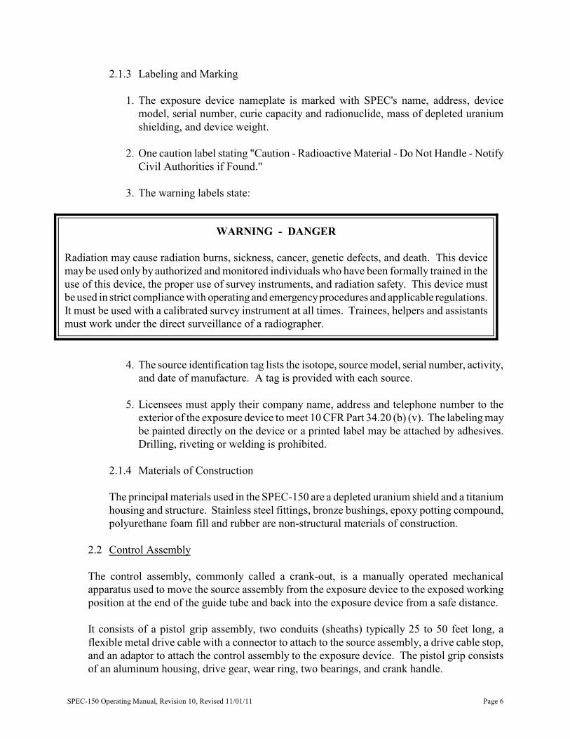
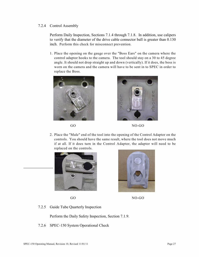
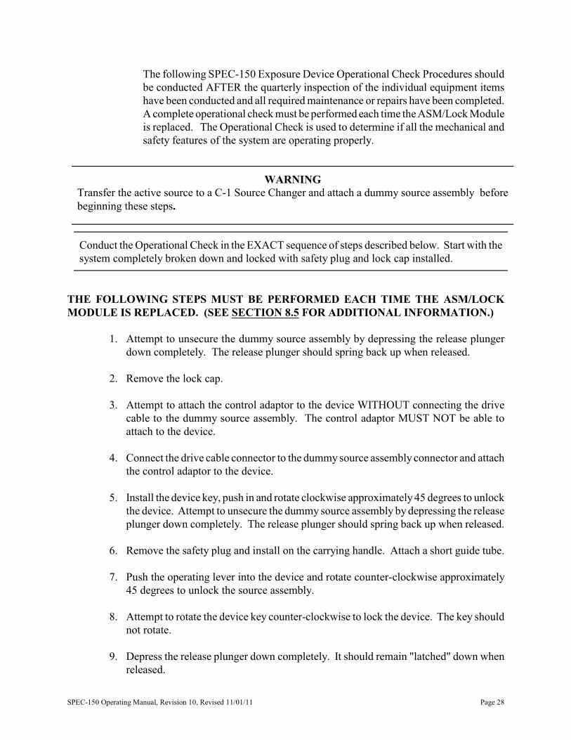
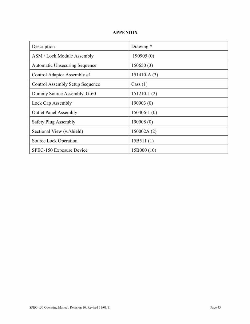
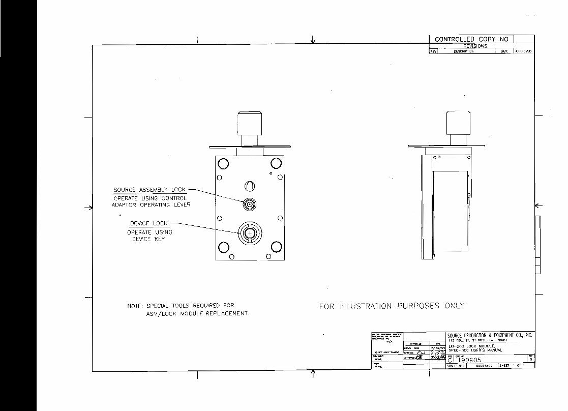
CONTROLLED COpy NO REVISIONS
DESCRIPTION )An 1APROJEO
hocgt0 0 D
0 0
0 ([])SOURCE ASSEMBLY LOCK
OPERATE USING CONTROL ADAPTOR OPERATING LEVER ~
0 0 DEVICE LOCK
OPERATE USING DlVICE KEY
~0 0 0 0
NOTE SPECIAL TOOLS REQUIRED FOR FOR ILLUSTRATION PURPOSES ONLY MODULE REPLACEMENT
---~ -~~ A 1__ t1lV- ~ _~
lIOamstA1~ MtltIB e~-
CONTRDLLED COpy ___
REVISIONS lJAT~ APPROVED
ECRH 970811-4 10-1-97 S BYRD CHANGE DRAWiNG TiTLE TO READ AUTO4ATlC UNSECURING O-It7 ptJ SEQUENCE CHANGE DRAWING NUMBER TO CORRESPOND WITH THt SPEC-15D NUMBERING SYSTEM
P~ (D SECURED reg UNSECURED
( RELEASE PLUNGER WCHED DoWN )
~I~ ~rshy
CRANKING FORWARD CRANKING FORWARD
( UNlATCHING RElfAlE PLUNGER ) ( TO txPOSE SOURCE I
1MLISS~PJCnSll DDlEKSIOMS AX Dr fN(lpoundS SOURCE PRODUCTION amp EQUIPMENT CO INC lOuJAIIltEO ARE 113 TEAL ST ST ROSE LA 70087PRAC11OMS DtcIlUlS
Inco IXlXt010
1Pnov~ ~ ASfv1 AUTOMATIC UNSECLJRING SEQUENCE 7- 14-95
DC 1N0t 9IllJ DIUWlyenC SPEC- 150 EXPOSURE OEVICE
ck1XKl) r rvnmiddotLt I1~~r---=l- ROOt i3T15065o 3 00031503NONE QA CUS1 NA
CONTROLLED COpy NO REVISIONS
REV I 0poundSCICIPT10H (l) IlNCORPORAlED poundCAl 040l09-1
O-RING
shy----=tr -r I -- -==Jshy -L ~J
I L
OPERATING LEVER
ROTATE TO UNLOCK SOURCE ASSEMBLY
OPERATING LEVER SPRING
INC
-NIl ~ s8lR)
1lO1CiIU~ P WEBERI20111 _ ADO 1210
NOfeuro J -shy-IltOfeuro I N
RElpoundASpound PLUNGER
CD SOURCE ASSEIdBLY CONNECTOR
CQNTROL AITACHMENT BOSS
CONTROL ASSEMBlI AOAPTOfi
OPERATING (SlOE 11[00) LEVER HOLE
u - N
o L ~ 0
L OPEflATING lElERc C
K tlt STOPPIN ~ ~ ltgt D~gEEY reg middot reg u ~rI
~ DEVICE KEY
~~===============~ (SJ[)EVlfW)
CD CONlf1Oll5SEItSl Y A[)APTOR
STOP PIN II
STEPS Ii ADACH DRIVE CSLE TO SOURCE ASSEMBLY ill N2 ATIACH CONTROL ADAPTOR TO ATTACHMENT BOSS (i)
3 ROTATE CONTROL ADAPTOR AGAINST STOP PIN
INSERT DEVICE KEY ANO ROTATE CLOCKWISE
5 INSERT OFERTlNG LEVER AND ROTAiE COUNTpoundR CLOCKWISE
o CONTROL ASSpoundMBlY IUlAPTOR
L o f -11- OPERA1ING lEVERC (PUSH AND TURNK to UNLOCK SOURCE)
~ K II OEYICE KEYSTOP PIN --tI------ (PUSH tiD TURN
TO UNLOCK DpoundVICE)
SPEC-1 ~o CONrROllISSEWaLY SETUP 5 tQUCHer Al[ NAME CASS(l) 39ffl1lo o-u-es
CONTROLLED COPY REVISIONS
REVI 0EiCRIPll0H (2) jlNCOfUORAlm ECRI IJ40609-J
lOCIlt1NG ampU
CAISUlE ---- I-M ----1
5OlJRa ~y CIoIU
1-------------------- 1-11 I
nu wao
MATERIAL SEE SPECIFIC PART DRAWING
ao SOOOCE PROOUCTION Ie EOJIPIIENT CO INC--shy-- III IDl ST ST ROSt IA I1lOII7-- ~ DUUIAY SOURCE ASSEUBlYshy_ 11IIIIl_WllIOIU ___ lZ8l1- 140DEl G-60 - _ow Vl2~ SPEC-1SO EX
-ROO t12te- Cgt-8 1I01227021SHEEl
CONTROLLED COPY NO REVISIONS
O(SCRIPTrn DATE I NPROiEO
o
FOR ILLUSTRATION PURPOS ONLY
-shy- SOURCE PRODUCTiON amp EQUIPIAENl CO INC
- DO oootlCMt ~ioJIofci
litpoundA1j[lol
Nt
~~~C1~~~~~~~~~middotO NOH
I 434
MATERIAL
PANEL amp BOSS TITANIUM
OUTLET NIPPLE STAINLESS STEEL
NOTE SPECIAL TOOL REOUIRED
CONTROLLED COPY ~J
SH~ET 1 OF 1
902rshy1 shy
2 58
--------shy
1 ~~ 18
14 seCURITY ~ SCREW 4 EA
NOTE
TOLERANCES REVISIONS SOURCE PRODUCTION amp EOUIPMENT COINC (EXCEPT AS NOTEOU DWG IAPPD 113 TEAL ST ST ROSE LA 70087DATE BY BYDECIMAL
1 SPEC 150 EXPOSURE DEVICE ~I OUTLET PANEL ASSEMBLY
2 MATERIAL-------+-----1----11 DR~WN BY ISCALE
3 S BYRD 1 TO 1 I NOTED +- CHKD BY
ANGULAR ~ J F i t~ QA CLASSn+- O-B
I J c()NTROLLED COpy NO I ~ I REVISIONS IREVI OESCIlif1I0N I oaTEJAP~
-~
~ ~ IITr-II II I ~ ~ ~ II lLJj-- ~ ~
~ ~
FOR ILLUSTRATION PURPOSES ONLY
gtUllS0gt~~ ~scNlltlIi SOURCE PRODUCTION amp EQUiPMENT CObull INC
I-~ 113 rEAL ~J 51 ROSE LA 70087
-- ]l299 SAFE1Y PLUG ASSEMBLY _ o SPEC-30Q USERS MANUAL
~~~KL[~ -- bull 1lt NgtfgtJCtiltIlitIaV( M~9C Ci90908 1I~
SCALE ~Fo~e4500---rSH(poundT t OF 1 I l
HANDLE ASSEMBLY ----J
RELEASE PLUNGER
SOURCE ASSEMBLY
LOCK CAP ASSEMBLY
REVISIONSTIE-DOWN FOAM FILL HOLE I DATE 1 DWGBY
NOTE 1 OUTLET END FLANGE ATTACHMENT BOSS IS MOUNTED I NA 113-14-951 S8 +~
TO THE LEFT INSIDE WALL OF THE OUTLET END FLANGLFRAcnoNAL 2 12-27-971 S8 3
4
000001951+~ NA 15
SHEET 1 OF 1
PROTECTIVE FLANGE
OUTLET END FLANGE ATIACHMENT
BOSS NOTE 1
OUTLET PANEL ASSEMBLY
SAFETY PLUG ASSEMBLY
SOURCE PRODUCTION amp EQUIPMENT COINC 113 TEAL ST ST ROSE LA 70087 SPEC 150 EXPOSURE DEVICE
FULL SECTIONAL VIEW i __ bullbull ~ i-~----I
NOTES
1
amp amp
VIEWS ARE tROll THE LOCK END
SOURCE ASSEIIBLY CONNECTOR
LOCKING BAlL
or THE DEVICE
CONTROLLED COpy REVISIONS
REV QESCRlPllON
(1) 1NCORPltlRAroJ [CR 04ltl6OlJ-4
NO
OAT NIROI(ll
I
I
C) I
I
~
SOURCE LOCK CLOSED SOURCE LOCK OPEN
~~I -
_rA _ampIE --
MrA ~ N
shy Cgt-4
ISOURc[ PROWCllON amp EOOIPUENT CO INCol 113 TO Sf ST ROSE LA 70087
1_ ~__ OPERATlONshy
00122amp01 ISHEEf 1 OF I
CONTROLLED COpy NO REVISIONS
STATEI4ENTS OF FABRICAITON REV DESCRIPTION DATE APPROIIED
(I) SEE IlA nLE rOLDpoundR 158000 3-6-95 S BYRD 3-6-95 KC 3-6-95 ROO
1 SUPPLEI4ENTAL SHIELDING Ir NEEDED TO I4EET NORI4AL CONDmON DOSE RATE lIl4lTS IS ATTACHED TO THE SHIELD OR OTHER PACKAGE COI4PONENTS
(2) SEE IlA nLE fOLDER l5BOOO 4-5-95 S BYRDUSING ALUt4INUI4 EPOXY POTTING COI4POUND THE SUPPLEI4ENTAL SHIELDING 4-5-95 KC CONSISTS OF ONE POUND OR LESS OF DEPLETED URANIUI4 TUNGSTEN OR LEAD 4-5-95 ROO
(3) SEE IlA nu fOLDER l5BOOO 4-14-95 S BYRD2 I4AXII4UI4 WEIGHT 535 LBS 4-14-95 KC 4-14-95 ROO
3 SEE DRAWING 1 5BOOl -3 FOR I4ATERIAl SPECIFICATIONS FoR SERIAl NUI4BERS 1475 AND NEWER (4) SEE IlA nu fOLDER l5BOOO 9-21-95 S BYRD
HOUSING COVER IS 332 THICK 9-21-95 KC OUTLET END SUPPORT CUP amplt BULKHEADS ARE 18 THICK 9-21-95 ROO
INNER SUPPORT CUP IS 2 NOI4INAL SCHEDULE 10 PIPE (5) INCORPORATED [CRI 981007-02 10-15-98 5 BYRD BOTTOI4 PLATE (BASE) IS 316 THICK SOURCE IDENTIFICATION 4-20-99 RAIl
TAG 4-20-99 ROD
(6) IINCORPORATEO [CRI 990506-04 5-6-99 S BYRD CARRYING HANDLE 5-6-99 RAIl
5-6-99 ROD(OPTIONAL) (7) INCORPORATED CRI 000166 13- 10- 09 KP
RELEASE 3-11-09 KR 3-11-09 KR
CAUTION All CHANGES ARE IN MQ 1 I MQl 1101 ASI4LOCK 140DULE
DO bullbullbull ~ tWIll[ bull _
4X UPPER 140UNTING HoLES (OPTIONAL)RADIOACTIVE MATERIAL
~ SAFETY PLUG
4X LOWER 140UNTING HOLES
LOCK CAP Ybf
lt )
~ -s~
_-~_1iIOtE5 SOURCE PRODUCTION amp EQUIPMENT CO INC-
113 TEAl ST ST ROSE LA 70087 ~ NOTED 1_-- 12--1 SPEC-150 TYPE B(U) PACKAGE
DONOfDU 1101 Iv1 0 ISOt4ETRIC VIEW- 1101 11v101 C1158000 110- Ql aass HI
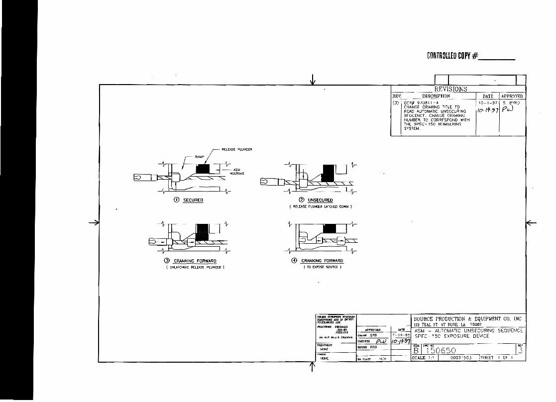
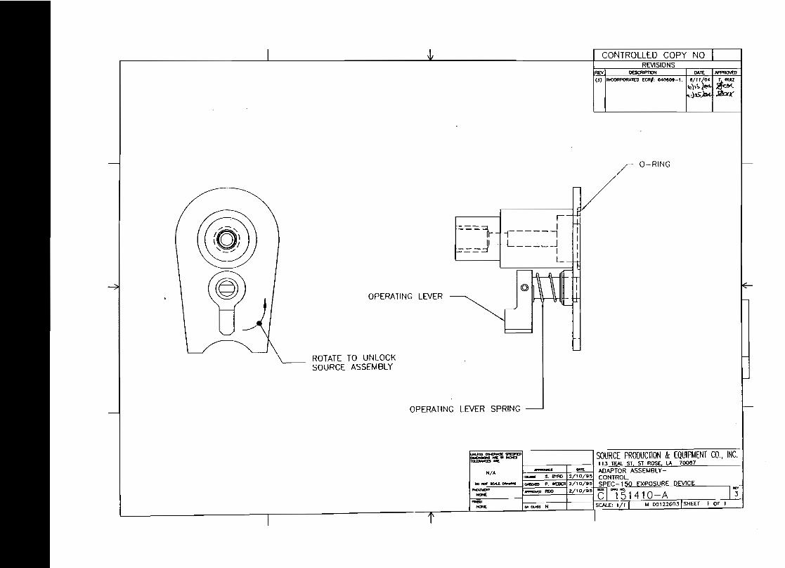
CONTROLLED COpy NO REVISIONS
REV I 0poundSCICIPT10H (l) IlNCORPORAlED poundCAl 040l09-1
O-RING
shy----=tr -r I -- -==Jshy -L ~J
I L
OPERATING LEVER
ROTATE TO UNLOCK SOURCE ASSEMBLY
OPERATING LEVER SPRING
INC
-NIl ~ s8lR)
1lO1CiIU~ P WEBERI20111 _ ADO 1210
NOfeuro J -shy-IltOfeuro I N
RElpoundASpound PLUNGER
CD SOURCE ASSEIdBLY CONNECTOR
CQNTROL AITACHMENT BOSS
CONTROL ASSEMBlI AOAPTOfi
OPERATING (SlOE 11[00) LEVER HOLE
u - N
o L ~ 0
L OPEflATING lElERc C
K tlt STOPPIN ~ ~ ltgt D~gEEY reg middot reg u ~rI
~ DEVICE KEY
~~===============~ (SJ[)EVlfW)
CD CONlf1Oll5SEItSl Y A[)APTOR
STOP PIN II
STEPS Ii ADACH DRIVE CSLE TO SOURCE ASSEMBLY ill N2 ATIACH CONTROL ADAPTOR TO ATTACHMENT BOSS (i)
3 ROTATE CONTROL ADAPTOR AGAINST STOP PIN
INSERT DEVICE KEY ANO ROTATE CLOCKWISE
5 INSERT OFERTlNG LEVER AND ROTAiE COUNTpoundR CLOCKWISE
o CONTROL ASSpoundMBlY IUlAPTOR
L o f -11- OPERA1ING lEVERC (PUSH AND TURNK to UNLOCK SOURCE)
~ K II OEYICE KEYSTOP PIN --tI------ (PUSH tiD TURN
TO UNLOCK DpoundVICE)
SPEC-1 ~o CONrROllISSEWaLY SETUP 5 tQUCHer Al[ NAME CASS(l) 39ffl1lo o-u-es
CONTROLLED COPY REVISIONS
REVI 0EiCRIPll0H (2) jlNCOfUORAlm ECRI IJ40609-J
lOCIlt1NG ampU
CAISUlE ---- I-M ----1
5OlJRa ~y CIoIU
1-------------------- 1-11 I
nu wao
MATERIAL SEE SPECIFIC PART DRAWING
ao SOOOCE PROOUCTION Ie EOJIPIIENT CO INC--shy-- III IDl ST ST ROSt IA I1lOII7-- ~ DUUIAY SOURCE ASSEUBlYshy_ 11IIIIl_WllIOIU ___ lZ8l1- 140DEl G-60 - _ow Vl2~ SPEC-1SO EX
-ROO t12te- Cgt-8 1I01227021SHEEl
CONTROLLED COPY NO REVISIONS
O(SCRIPTrn DATE I NPROiEO
o
FOR ILLUSTRATION PURPOS ONLY
-shy- SOURCE PRODUCTiON amp EQUIPIAENl CO INC
- DO oootlCMt ~ioJIofci
litpoundA1j[lol
Nt
~~~C1~~~~~~~~~middotO NOH
I 434
MATERIAL
PANEL amp BOSS TITANIUM
OUTLET NIPPLE STAINLESS STEEL
NOTE SPECIAL TOOL REOUIRED
CONTROLLED COPY ~J
SH~ET 1 OF 1
902rshy1 shy
2 58
--------shy
1 ~~ 18
14 seCURITY ~ SCREW 4 EA
NOTE
TOLERANCES REVISIONS SOURCE PRODUCTION amp EOUIPMENT COINC (EXCEPT AS NOTEOU DWG IAPPD 113 TEAL ST ST ROSE LA 70087DATE BY BYDECIMAL
1 SPEC 150 EXPOSURE DEVICE ~I OUTLET PANEL ASSEMBLY
2 MATERIAL-------+-----1----11 DR~WN BY ISCALE
3 S BYRD 1 TO 1 I NOTED +- CHKD BY
ANGULAR ~ J F i t~ QA CLASSn+- O-B
I J c()NTROLLED COpy NO I ~ I REVISIONS IREVI OESCIlif1I0N I oaTEJAP~
-~
~ ~ IITr-II II I ~ ~ ~ II lLJj-- ~ ~
~ ~
FOR ILLUSTRATION PURPOSES ONLY
gtUllS0gt~~ ~scNlltlIi SOURCE PRODUCTION amp EQUiPMENT CObull INC
I-~ 113 rEAL ~J 51 ROSE LA 70087
-- ]l299 SAFE1Y PLUG ASSEMBLY _ o SPEC-30Q USERS MANUAL
~~~KL[~ -- bull 1lt NgtfgtJCtiltIlitIaV( M~9C Ci90908 1I~
SCALE ~Fo~e4500---rSH(poundT t OF 1 I l
HANDLE ASSEMBLY ----J
RELEASE PLUNGER
SOURCE ASSEMBLY
LOCK CAP ASSEMBLY
REVISIONSTIE-DOWN FOAM FILL HOLE I DATE 1 DWGBY
NOTE 1 OUTLET END FLANGE ATTACHMENT BOSS IS MOUNTED I NA 113-14-951 S8 +~
TO THE LEFT INSIDE WALL OF THE OUTLET END FLANGLFRAcnoNAL 2 12-27-971 S8 3
4
000001951+~ NA 15
SHEET 1 OF 1
PROTECTIVE FLANGE
OUTLET END FLANGE ATIACHMENT
BOSS NOTE 1
OUTLET PANEL ASSEMBLY
SAFETY PLUG ASSEMBLY
SOURCE PRODUCTION amp EQUIPMENT COINC 113 TEAL ST ST ROSE LA 70087 SPEC 150 EXPOSURE DEVICE
FULL SECTIONAL VIEW i __ bullbull ~ i-~----I
NOTES
1
amp amp
VIEWS ARE tROll THE LOCK END
SOURCE ASSEIIBLY CONNECTOR
LOCKING BAlL
or THE DEVICE
CONTROLLED COpy REVISIONS
REV QESCRlPllON
(1) 1NCORPltlRAroJ [CR 04ltl6OlJ-4
NO
OAT NIROI(ll
I
I
C) I
I
~
SOURCE LOCK CLOSED SOURCE LOCK OPEN
~~I -
_rA _ampIE --
MrA ~ N
shy Cgt-4
ISOURc[ PROWCllON amp EOOIPUENT CO INCol 113 TO Sf ST ROSE LA 70087
1_ ~__ OPERATlONshy
00122amp01 ISHEEf 1 OF I
CONTROLLED COpy NO REVISIONS
STATEI4ENTS OF FABRICAITON REV DESCRIPTION DATE APPROIIED
(I) SEE IlA nLE rOLDpoundR 158000 3-6-95 S BYRD 3-6-95 KC 3-6-95 ROO
1 SUPPLEI4ENTAL SHIELDING Ir NEEDED TO I4EET NORI4AL CONDmON DOSE RATE lIl4lTS IS ATTACHED TO THE SHIELD OR OTHER PACKAGE COI4PONENTS
(2) SEE IlA nLE fOLDER l5BOOO 4-5-95 S BYRDUSING ALUt4INUI4 EPOXY POTTING COI4POUND THE SUPPLEI4ENTAL SHIELDING 4-5-95 KC CONSISTS OF ONE POUND OR LESS OF DEPLETED URANIUI4 TUNGSTEN OR LEAD 4-5-95 ROO
(3) SEE IlA nu fOLDER l5BOOO 4-14-95 S BYRD2 I4AXII4UI4 WEIGHT 535 LBS 4-14-95 KC 4-14-95 ROO
3 SEE DRAWING 1 5BOOl -3 FOR I4ATERIAl SPECIFICATIONS FoR SERIAl NUI4BERS 1475 AND NEWER (4) SEE IlA nu fOLDER l5BOOO 9-21-95 S BYRD
HOUSING COVER IS 332 THICK 9-21-95 KC OUTLET END SUPPORT CUP amplt BULKHEADS ARE 18 THICK 9-21-95 ROO
INNER SUPPORT CUP IS 2 NOI4INAL SCHEDULE 10 PIPE (5) INCORPORATED [CRI 981007-02 10-15-98 5 BYRD BOTTOI4 PLATE (BASE) IS 316 THICK SOURCE IDENTIFICATION 4-20-99 RAIl
TAG 4-20-99 ROD
(6) IINCORPORATEO [CRI 990506-04 5-6-99 S BYRD CARRYING HANDLE 5-6-99 RAIl
5-6-99 ROD(OPTIONAL) (7) INCORPORATED CRI 000166 13- 10- 09 KP
RELEASE 3-11-09 KR 3-11-09 KR
CAUTION All CHANGES ARE IN MQ 1 I MQl 1101 ASI4LOCK 140DULE
DO bullbullbull ~ tWIll[ bull _
4X UPPER 140UNTING HoLES (OPTIONAL)RADIOACTIVE MATERIAL
~ SAFETY PLUG
4X LOWER 140UNTING HOLES
LOCK CAP Ybf
lt )
~ -s~
_-~_1iIOtE5 SOURCE PRODUCTION amp EQUIPMENT CO INC-
113 TEAl ST ST ROSE LA 70087 ~ NOTED 1_-- 12--1 SPEC-150 TYPE B(U) PACKAGE
DONOfDU 1101 Iv1 0 ISOt4ETRIC VIEW- 1101 11v101 C1158000 110- Ql aass HI
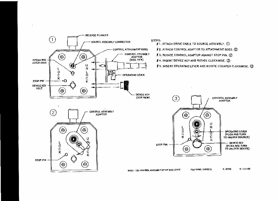
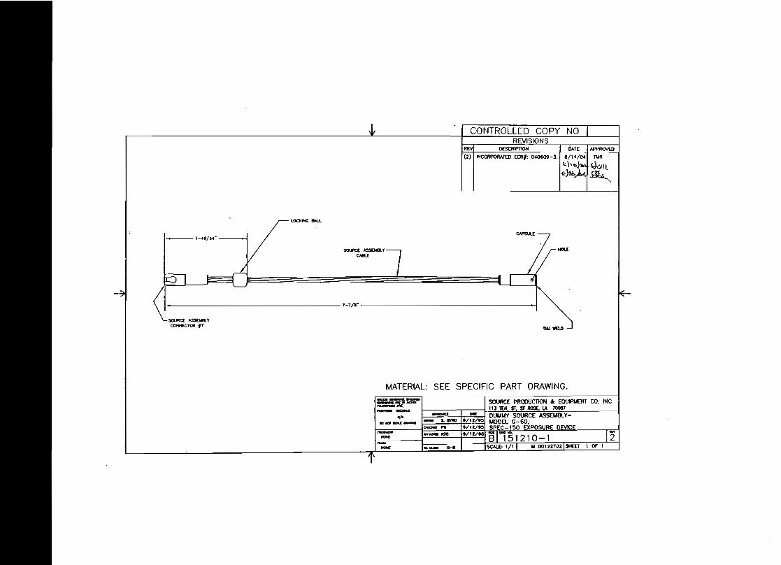
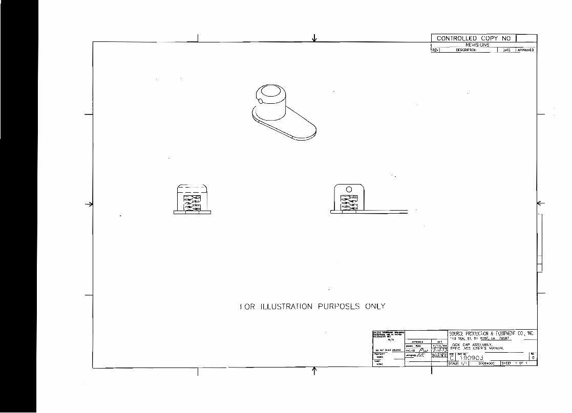
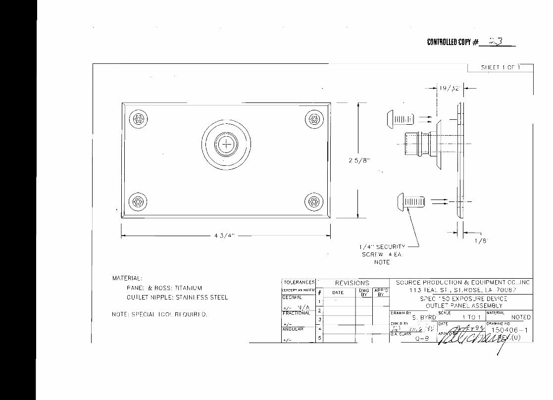
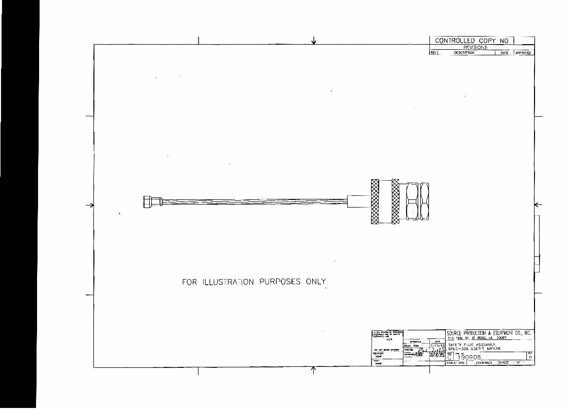
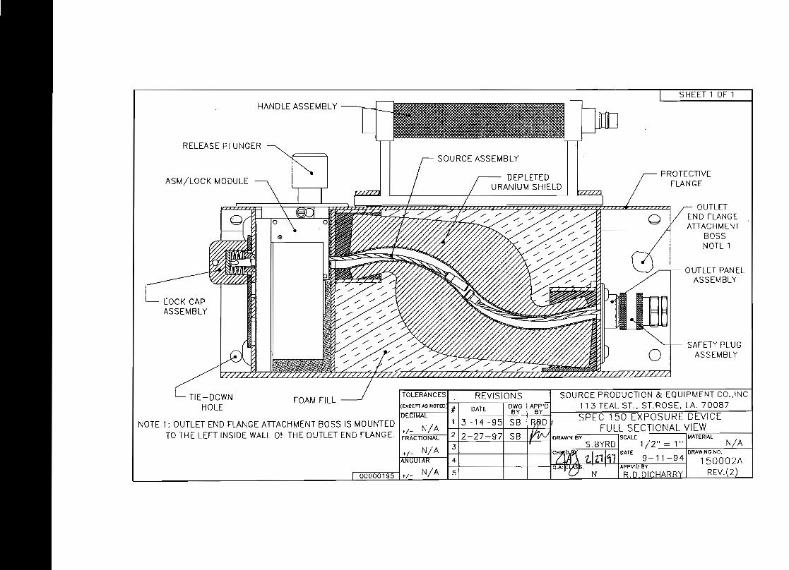
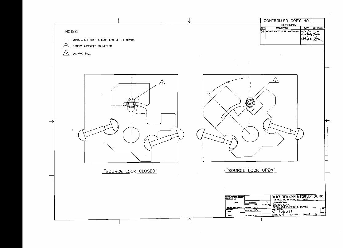
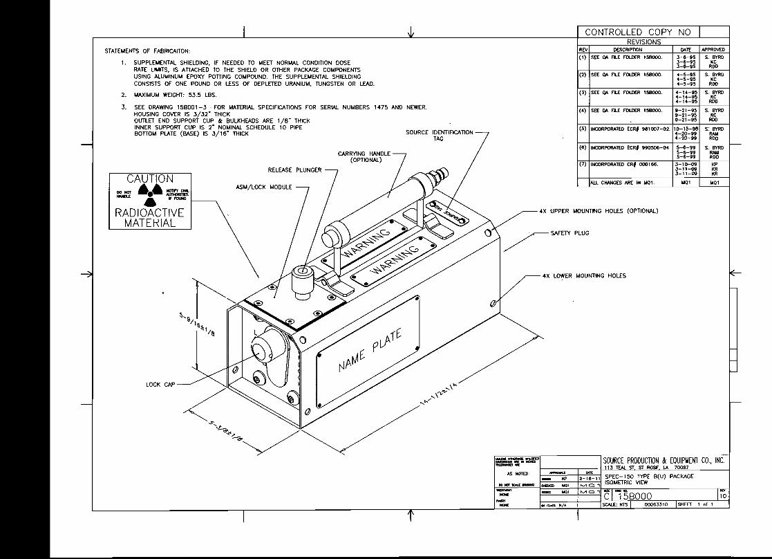


![[Radiography] Technique - Exposure Factors. KVP = Energy of x-rays = higher penetrability, it moves through tissue. The energy determines the QUALITY](https://img.pdfslide.us/doc/110x75/5517c9ad550346892b8b4c78/radiography-technique-exposure-factors-kvp-energy-of-x-rays-higher-penetrability-it-moves-through-tissue-the-energy-determines-the-quality.jpg)