Embed Size (px)
Citation preview

Model Solu Comp® Xmt-TTwo-Wire Toroidal Conductivity Transmitter
Instruction ManualPN 51-Xmt-T/rev.C
February 2006
Emerson Process Management
Rosemount Analytical Inc.2400 Barranca Parkway
Irvine, CA 92606 USA
Tel: (949) 757-8500
Fax: (949) 474-7250
http://www.raihome.com
© Rosemount Analytical Inc. 2006
ESSENTIAL INSTRUCTIONSREAD THIS PAGE BEFORE PROCEEDING!
Rosemount Analytical designs, manufactures, and tests its products to meet many national and internationalstandards. Because these instruments are sophisticated technical products, you must properly install, use, andmaintain them to ensure they continue to operate within their normal specifications. The following instructionsmust be adhered to and integrated into your safety program when installing, using, and maintaining RosemountAnalytical products. Failure to follow the proper instructions may cause any one of the following situations tooccur: Loss of life; personal injury; property damage; damage to this instrument; and warranty invalidation.
• Read all instructions prior to installing, operating, and servicing the product. If this Instruction Manual is not thecorrect manual, telephone 1-800-654-7768 and the requested manual will be provided. Save this InstructionManual for future reference.
• If you do not understand any of the instructions, contact your Rosemount representative for clarification.
• Follow all warnings, cautions, and instructions marked on and supplied with the product.
• Inform and educate your personnel in the proper installation, operation, and maintenance of the product.
• Install your equipment as specified in the Installation Instructions of the appropriate Instruction Manual and perapplicable local and national codes. Connect all products to the proper electrical and pressure sources.
• To ensure proper performance, use qualified personnel to install, operate, update, program, and maintain theproduct.
• When replacement parts are required, ensure that qualified people use replacement parts specified byRosemount. Unauthorized parts and procedures can affect the product’s performance and place the safeoperation of your process at risk. Look alike substitutions may result in fire, electrical hazards, or improperoperation.
• Ensure that all equipment doors are closed and protective covers are in place, except when maintenance isbeing performed by qualified persons, to prevent electrical shock and personal injury.
NOTICEIf a Model 375 Universal Hart® Communicator is used with these transmitters, the software within the Model 375 may require
modification. If a software modification is required, please contact your local Emerson Process Management Service Group
or National Response Center at 1-800-654-7768.
About This Document
This manual contains instructions for installation and operation of the Model Xmt-T Two-Wire Toroidal
Conductivity Transmitter. The following list provides notes concerning all revisions of this document.
Rev. Level Date Notes
A 3/05 This is the initial release of the product manual. The manual has been
reformatted to reflect the Emerson documentation style and updated to reflect
any changes in the product offering. This manual contains information on
HART Smart and FOUNDATION Fieldbus versions of Model Solu Comp Xmt-T.
B 10/05 Add Foundation fieldbus agency approvals and FISCO version.
C 2/06 Revised section 1.0, page 1, and the case specification on page 2. Added new
drawings of FF and FI on section 4.0, pages 24-35.
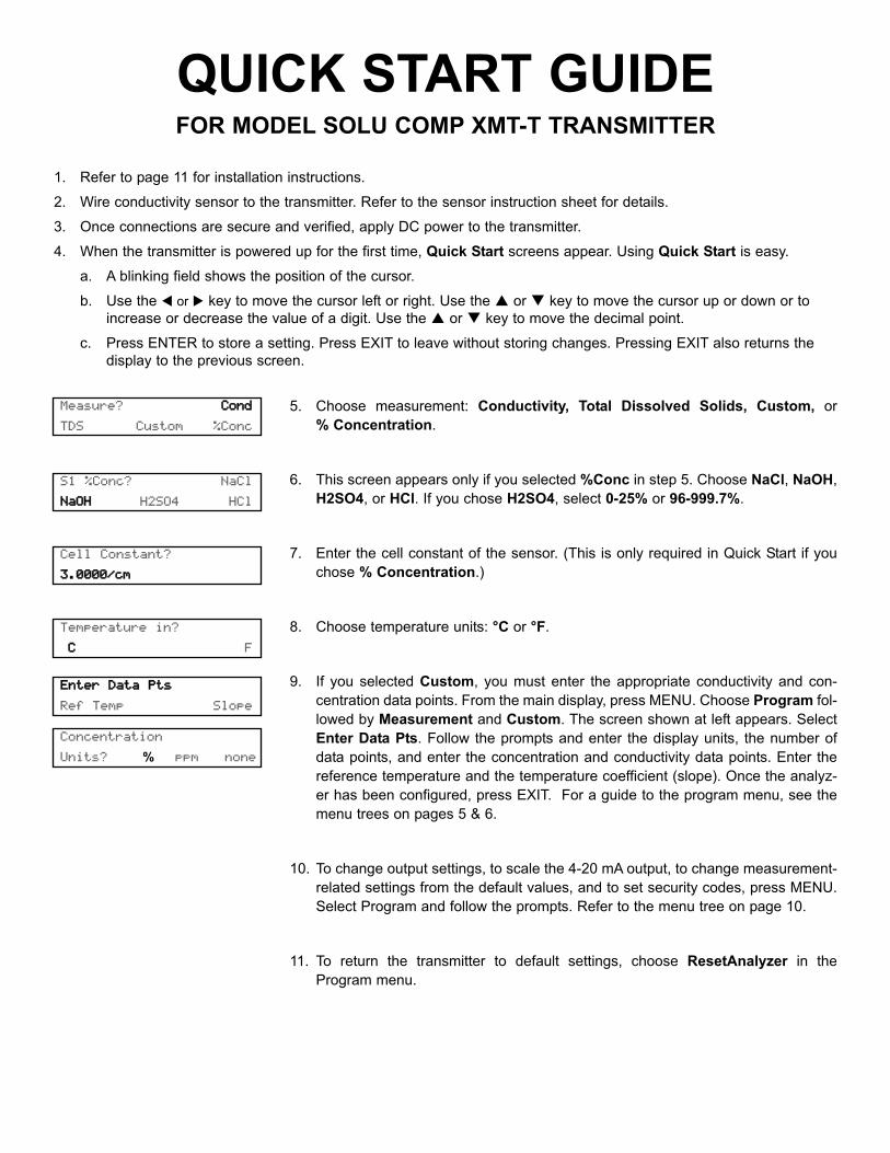
QUICK START GUIDEFOR MODEL SOLU COMP XMT-T TRANSMITTER
1. Refer to page 11 for installation instructions.
2. Wire conductivity sensor to the transmitter. Refer to the sensor instruction sheet for details.
3. Once connections are secure and verified, apply DC power to the transmitter.
4. When the transmitter is powered up for the first time, Quick Start screens appear. Using Quick Start is easy.
a. A blinking field shows the position of the cursor.
b. Use the or key to move the cursor left or right. Use the or key to move the cursor up or down or to
increase or decrease the value of a digit. Use the or key to move the decimal point.
c. Press ENTER to store a setting. Press EXIT to leave without storing changes. Pressing EXIT also returns the
display to the previous screen.
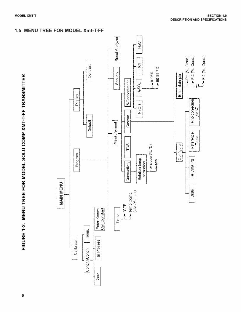
5. Choose measurement: Conductivity, Total Dissolved Solids, Custom, or
% Concentration.
6. This screen appears only if you selected %Conc in step 5. Choose NaCl, NaOH,
H2SO4, or HCl. If you chose H2SO4, select 0-25% or 96-999.7%.
7. Enter the cell constant of the sensor. (This is only required in Quick Start if you
chose % Concentration.)
8. Choose temperature units: °C or °F.
9. If you selected Custom, you must enter the appropriate conductivity and con-
centration data points. From the main display, press MENU. Choose Program fol-
lowed by Measurement and Custom. The screen shown at left appears. Select
Enter Data Pts. Follow the prompts and enter the display units, the number of
data points, and enter the concentration and conductivity data points. Enter the
reference temperature and the temperature coefficient (slope). Once the analyz-
er has been configured, press EXIT. For a guide to the program menu, see the
menu trees on pages 5 & 6.
10. To change output settings, to scale the 4-20 mA output, to change measurement-
related settings from the default values, and to set security codes, press MENU.
Select Program and follow the prompts. Refer to the menu tree on page 10.
11. To return the transmitter to default settings, choose ResetAnalyzer in the
Program menu.
Measure? CCoonndd
TDS Custom %Conc
S1 %Conc? NaCl
NNaaOOHH H2SO4 HCl
Cell Constant?
33..00000000//ccmm
Temperature in?
*CC *F
EEnntteerr DDaattaa PPttss
Ref Temp Slope
Concentration
Units? % ppm none
i
MODEL XMT-T TABLE OF CONTENTS
MODEL XMT-T TWO-WIRE CONDUCTIVITY TRANSMITTER
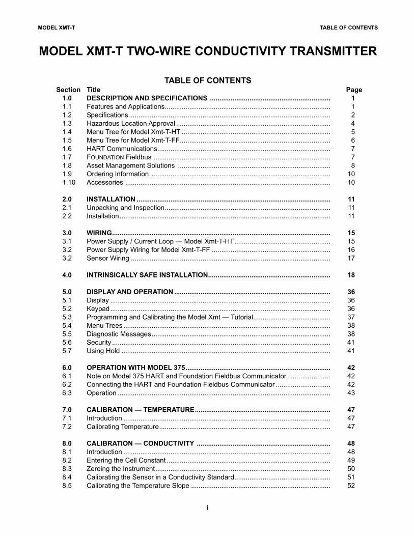
TABLE OF CONTENTSSection Title Page
1.0 DESCRIPTION AND SPECIFICATIONS ................................................................ 1
1.1 Features and Applications........................................................................................ 1
1.2 Specifications ........................................................................................................... 2
1.3 Hazardous Location Approval .................................................................................. 4
1.4 Menu Tree for Model Xmt-T-HT ............................................................................... 5
1.5 Menu Tree for Model Xmt-T-FF................................................................................ 6
1.6 HART Communications............................................................................................ 7
1.7 FOUNDATION Fieldbus .............................................................................................. 7
1.8 Asset Management Solutions ................................................................................. 8
1.9 Ordering Information ............................................................................................... 10
1.10 Accessories ............................................................................................................. 10
2.0 INSTALLATION ....................................................................................................... 11
2.1 Unpacking and Inspection........................................................................................ 11
2.2 Installation................................................................................................................ 11
3.0 WIRING.................................................................................................................... 15
3.1 Power Supply / Current Loop — Model Xmt-T-HT................................................... 15
3.2 Power Supply Wiring for Model Xmt-T-FF ............................................................... 16
3.2 Sensor Wiring .......................................................................................................... 17
4.0 INTRINSICALLY SAFE INSTALLATION................................................................. 18
5.0 DISPLAY AND OPERATION ................................................................................... 36
5.1 Display ..................................................................................................................... 36
5.2 Keypad..................................................................................................................... 36
5.3 Programming and Calibrating the Model Xmt — Tutorial......................................... 37
5.4 Menu Trees .............................................................................................................. 38
5.5 Diagnostic Messages............................................................................................... 38
5.6 Security .................................................................................................................... 41
5.7 Using Hold ............................................................................................................... 41
6.0 OPERATION WITH MODEL 375............................................................................. 42
6.1 Note on Model 375 HART and Foundation Fieldbus Communicator ....................... 42
6.2 Connecting the HART and Foundation Fieldbus Communicator ............................. 42
6.3 Operation ................................................................................................................. 43
7.0 CALIBRATION — TEMPERATURE........................................................................ 47
7.1 Introduction .............................................................................................................. 47
7.2 Calibrating Temperature........................................................................................... 47
8.0 CALIBRATION — CONDUCTIVITY ....................................................................... 48
8.1 Introduction .............................................................................................................. 48
8.2 Entering the Cell Constant ....................................................................................... 49
8.3 Zeroing the Instrument............................................................................................. 50
8.4 Calibrating the Sensor in a Conductivity Standard................................................... 51
8.5 Calibrating the Temperature Slope .......................................................................... 52
MODEL XMT-T TABLE OF CONTENTS
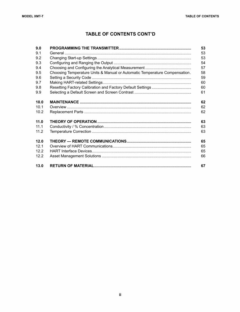
TABLE OF CONTENTS CONT’D
ii
9.0 PROGRAMMING THE TRANSMITTER.................................................................. 53
9.1 General .................................................................................................................... 53
9.2 Changing Start-up Settings ...................................................................................... 53
9.3 Configuring and Ranging the Output ....................................................................... 54
9.4 Choosing and Configuring the Analytical Measurement .......................................... 57
9.5 Choosing Temperature Units & Manual or Automatic Temperature Compensation . 58
9.6 Setting a Security Code ........................................................................................... 59
9.7 Making HART-related Settings................................................................................. 60
9.8 Resetting Factory Calibration and Factory Default Settings .................................... 60
9.9 Selecting a Default Screen and Screen Contrast .................................................... 61
10.0 MAINTENANCE ...................................................................................................... 62
10.1 Overview .................................................................................................................. 62
10.2 Replacement Parts .................................................................................................. 62
11.0 THEORY OF OPERATION ...................................................................................... 63
11.1 Conductivity / % Concentration................................................................................ 63
11.2 Temperature Correction ........................................................................................... 63
12.0 THEORY — REMOTE COMMUNICATIONS........................................................... 65
12.1 Overview of HART Communications........................................................................ 65
12.2 HART Interface Devices........................................................................................... 65
12.2 Asset Management Solutions .................................................................................. 66
13.0 RETURN OF MATERIAL......................................................................................... 67
iii
MODEL XMT-T TABLE OF CONTENTS
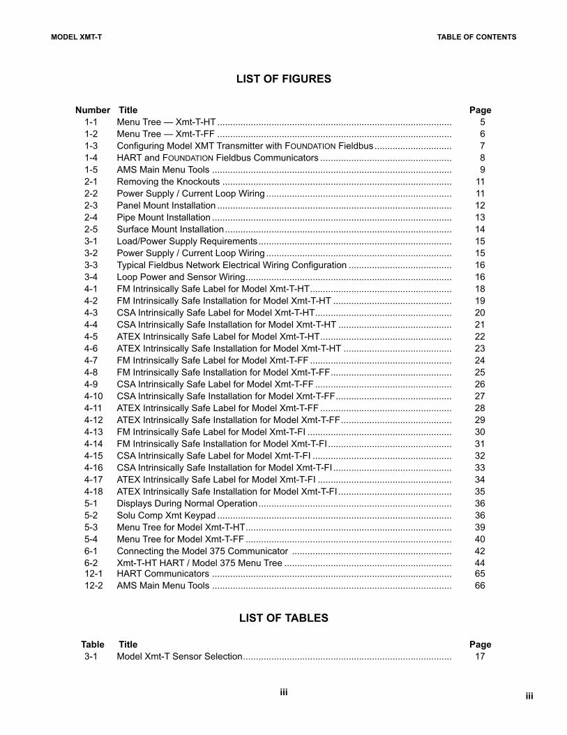
LIST OF FIGURES
iii
Number Title Page
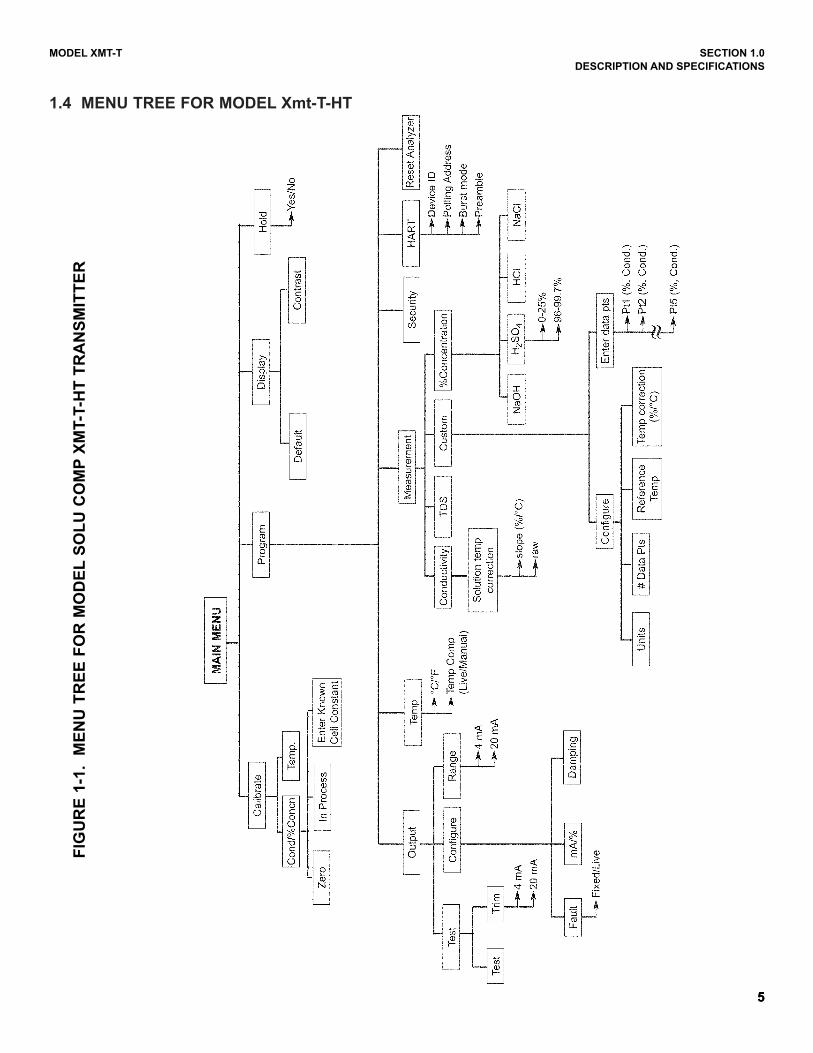
1-1 Menu Tree — Xmt-T-HT ........................................................................................... 5
1-2 Menu Tree — Xmt-T-FF ........................................................................................... 6
1-3 Configuring Model XMT Transmitter with FOUNDATION Fieldbus.............................. 7
1-4 HART and FOUNDATION Fieldbus Communicators ................................................... 8
1-5 AMS Main Menu Tools ............................................................................................. 9
2-1 Removing the Knockouts ......................................................................................... 11
2-2 Power Supply / Current Loop Wiring ........................................................................ 11
2-3 Panel Mount Installation ........................................................................................... 12
2-4 Pipe Mount Installation ............................................................................................. 13
2-5 Surface Mount Installation........................................................................................ 14
3-1 Load/Power Supply Requirements........................................................................... 15
3-2 Power Supply / Current Loop Wiring ........................................................................ 15
3-3 Typical Fieldbus Network Electrical Wiring Configuration ........................................ 16
3-4 Loop Power and Sensor Wiring................................................................................ 16
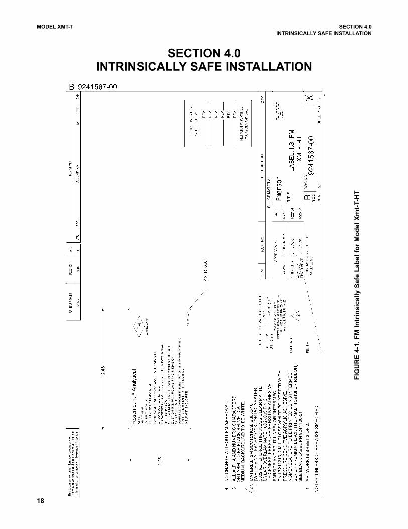
4-1 FM Intrinsically Safe Label for Model Xmt-T-HT....................................................... 18
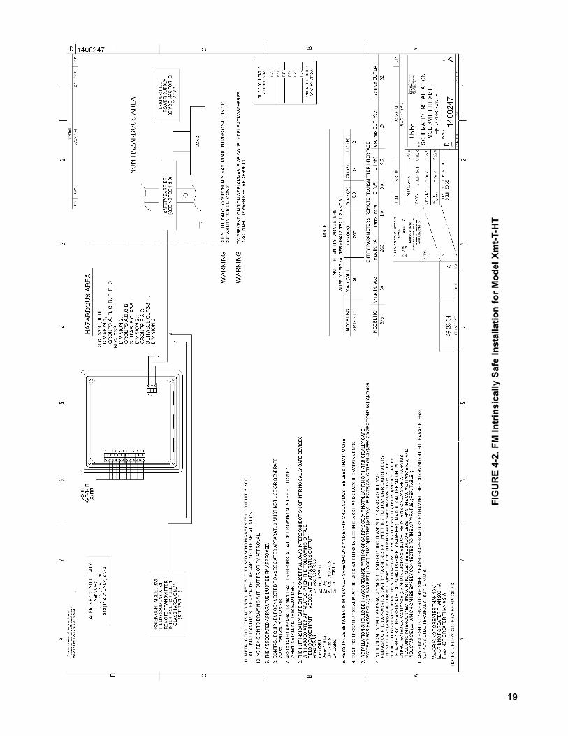
4-2 FM Intrinsically Safe Installation for Model Xmt-T-HT .............................................. 19
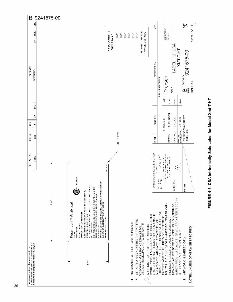
4-3 CSA Intrinsically Safe Label for Model Xmt-T-HT..................................................... 20
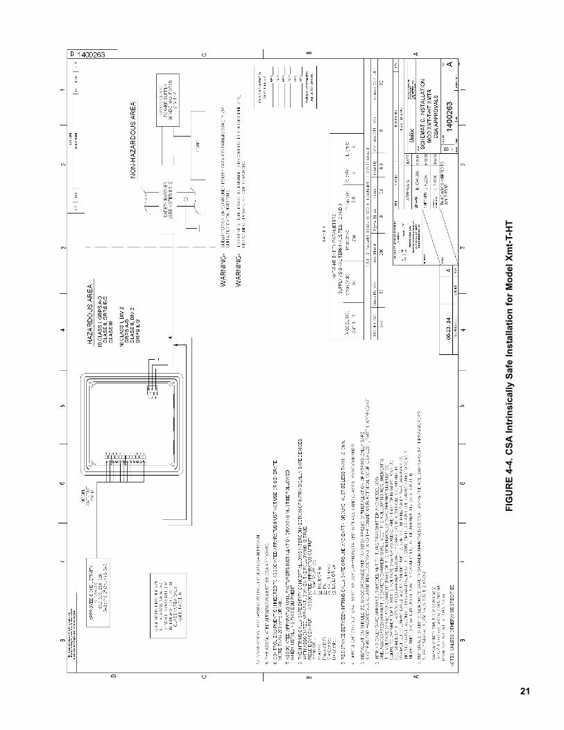
4-4 CSA Intrinsically Safe Installation for Model Xmt-T-HT ............................................ 21
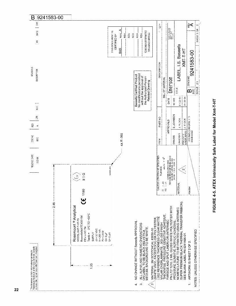
4-5 ATEX Intrinsically Safe Label for Model Xmt-T-HT................................................... 22
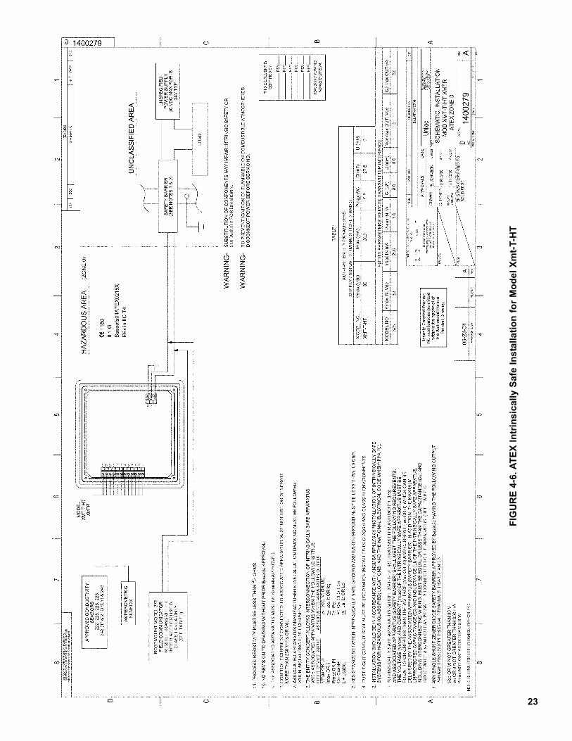
4-6 ATEX Intrinsically Safe Installation for Model Xmt-T-HT .......................................... 23
4-7 FM Intrinsically Safe Label for Model Xmt-T-FF ....................................................... 24
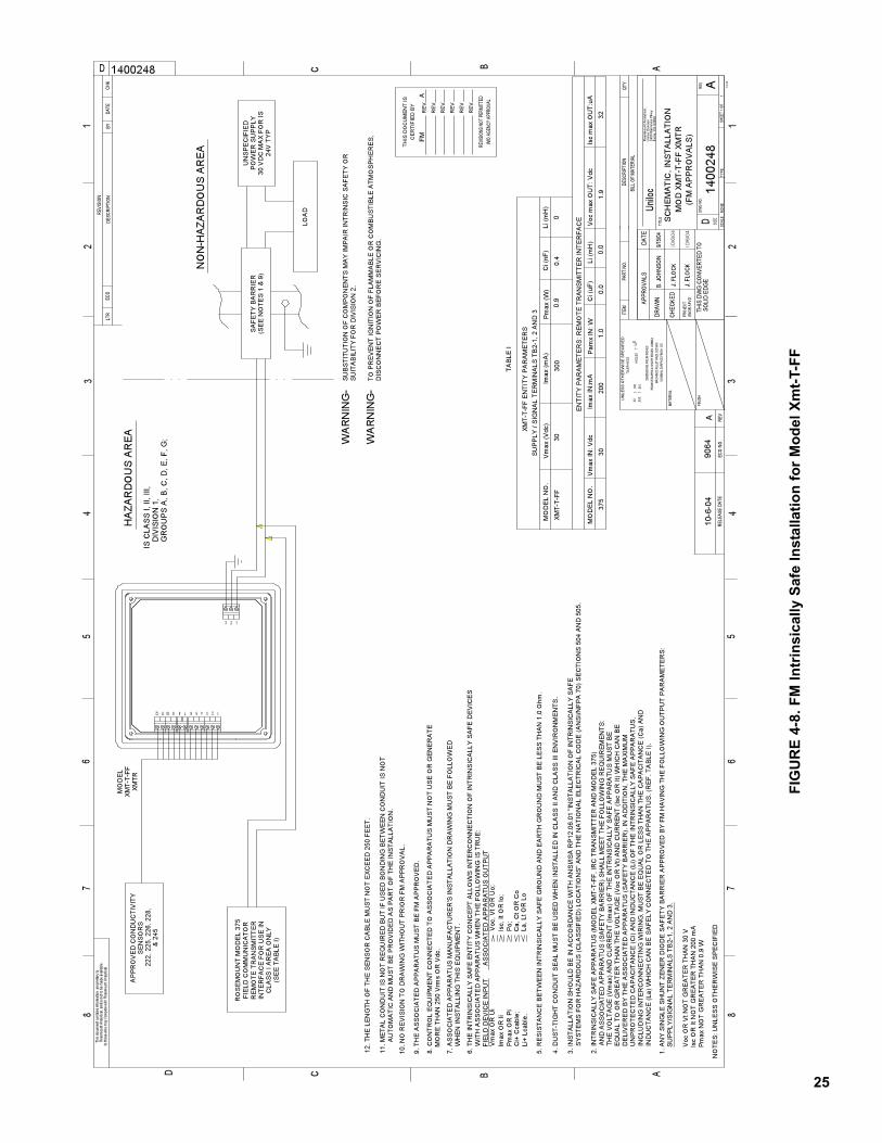
4-8 FM Intrinsically Safe Installation for Model Xmt-T-FF............................................... 25
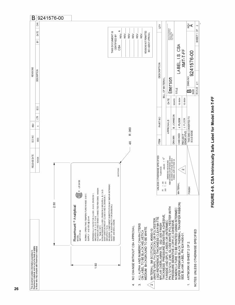
4-9 CSA Intrinsically Safe Label for Model Xmt-T-FF ..................................................... 26
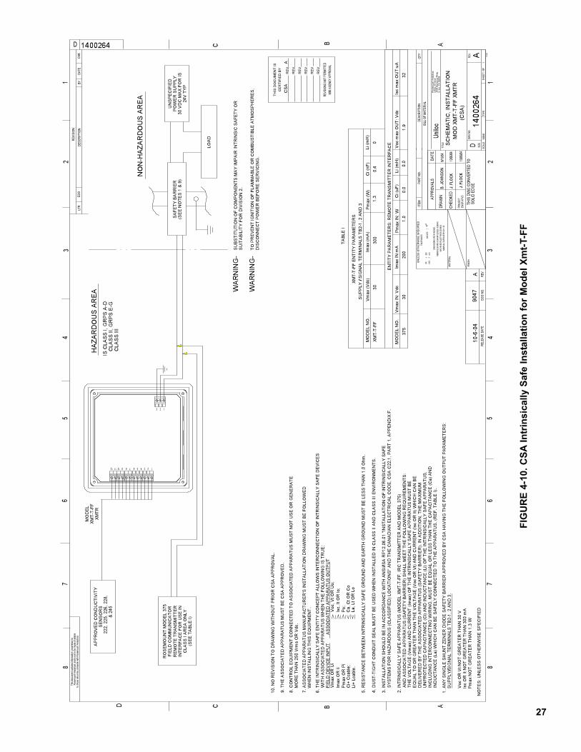
4-10 CSA Intrinsically Safe Installation for Model Xmt-T-FF............................................. 27
4-11 ATEX Intrinsically Safe Label for Model Xmt-T-FF ................................................... 28
4-12 ATEX Intrinsically Safe Installation for Model Xmt-T-FF........................................... 29
4-13 FM Intrinsically Safe Label for Model Xmt-T-FI ........................................................ 30
4-14 FM Intrinsically Safe Installation for Model Xmt-T-FI ................................................ 31
4-15 CSA Intrinsically Safe Label for Model Xmt-T-FI ...................................................... 32
4-16 CSA Intrinsically Safe Installation for Model Xmt-T-FI .............................................. 33
4-17 ATEX Intrinsically Safe Label for Model Xmt-T-FI .................................................... 34
4-18 ATEX Intrinsically Safe Installation for Model Xmt-T-FI ............................................ 35
5-1 Displays During Normal Operation........................................................................... 36
5-2 Solu Comp Xmt Keypad ........................................................................................... 36
5-3 Menu Tree for Model Xmt-T-HT................................................................................ 39
5-4 Menu Tree for Model Xmt-T-FF ................................................................................ 40
6-1 Connecting the Model 375 Communicator .............................................................. 42
6-2 Xmt-T-HT HART / Model 375 Menu Tree ................................................................. 4412-1 HART Communicators ............................................................................................. 65
12-2 AMS Main Menu Tools ............................................................................................. 66
LIST OF TABLES
Table Title Page
3-1 Model Xmt-T Sensor Selection................................................................................. 17

iv
1
MODEL XMT-T SECTION 1.0
DESCRIPTION AND SPECIFICATIONS
SECTION 1.0DESCRIPTION AND SPECIFICATIONS
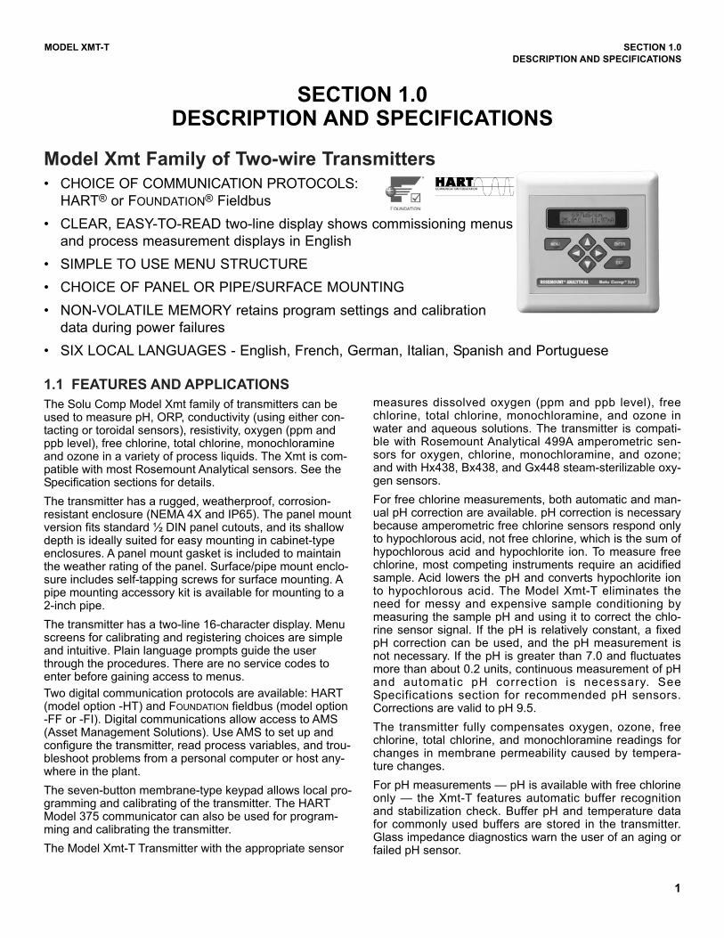
Model Xmt Family of Two-wire Transmitters
• CHOICE OF COMMUNICATION PROTOCOLS:
HART® or FOUNDATION® Fieldbus
• CLEAR, EASY-TO-READ two-line display shows commissioning menus
and process measurement displays in English
• SIMPLE TO USE MENU STRUCTURE
• CHOICE OF PANEL OR PIPE/SURFACE MOUNTING
• NON-VOLATILE MEMORY retains program settings and calibration
data during power failures
• SIX LOCAL LANGUAGES - English, French, German, Italian, Spanish and Portuguese
1.1 FEATURES AND APPLICATIONS
The Solu Comp Model Xmt family of transmitters can beused to measure pH, ORP, conductivity (using either con-tacting or toroidal sensors), resistivity, oxygen (ppm andppb level), free chlorine, total chlorine, monochloramineand ozone in a variety of process liquids. The Xmt is com-patible with most Rosemount Analytical sensors. See theSpecification sections for details.
The transmitter has a rugged, weatherproof, corrosion-resistant enclosure (NEMA 4X and IP65). The panel mountversion fits standard ½ DIN panel cutouts, and its shallowdepth is ideally suited for easy mounting in cabinet-typeenclosures. A panel mount gasket is included to maintainthe weather rating of the panel. Surface/pipe mount enclo-sure includes self-tapping screws for surface mounting. Apipe mounting accessory kit is available for mounting to a2-inch pipe.
The transmitter has a two-line 16-character display. Menuscreens for calibrating and registering choices are simpleand intuitive. Plain language prompts guide the userthrough the procedures. There are no service codes toenter before gaining access to menus.
Two digital communication protocols are available: HART(model option -HT) and FOUNDATION fieldbus (model option-FF or -FI). Digital communications allow access to AMS(Asset Management Solutions). Use AMS to set up andconfigure the transmitter, read process variables, and trou-bleshoot problems from a personal computer or host any-where in the plant.
The seven-button membrane-type keypad allows local pro-gramming and calibrating of the transmitter. The HARTModel 375 communicator can also be used for program-ming and calibrating the transmitter.
The Model Xmt-T Transmitter with the appropriate sensor
measures dissolved oxygen (ppm and ppb level), freechlorine, total chlorine, monochloramine, and ozone inwater and aqueous solutions. The transmitter is compati-ble with Rosemount Analytical 499A amperometric sen-sors for oxygen, chlorine, monochloramine, and ozone;and with Hx438, Bx438, and Gx448 steam-sterilizable oxy-gen sensors.
For free chlorine measurements, both automatic and man-ual pH correction are available. pH correction is necessarybecause amperometric free chlorine sensors respond onlyto hypochlorous acid, not free chlorine, which is the sum ofhypochlorous acid and hypochlorite ion. To measure freechlorine, most competing instruments require an acidifiedsample. Acid lowers the pH and converts hypochlorite ionto hypochlorous acid. The Model Xmt-T eliminates theneed for messy and expensive sample conditioning bymeasuring the sample pH and using it to correct the chlo-rine sensor signal. If the pH is relatively constant, a fixedpH correction can be used, and the pH measurement isnot necessary. If the pH is greater than 7.0 and fluctuatesmore than about 0.2 units, continuous measurement of pHand automatic pH correction is necessary. SeeSpecifications section for recommended pH sensors.Corrections are valid to pH 9.5.
The transmitter fully compensates oxygen, ozone, freechlorine, total chlorine, and monochloramine readings forchanges in membrane permeability caused by tempera-ture changes.
For pH measurements — pH is available with free chlorineonly — the Xmt-T features automatic buffer recognitionand stabilization check. Buffer pH and temperature datafor commonly used buffers are stored in the transmitter.Glass impedance diagnostics warn the user of an aging orfailed pH sensor.
2
MODEL XMT-T SECTION 1.0
DESCRIPTION AND SPECIFICATIONS
1.2 SPECIFICATIONS
1.2.1 GENERAL SPECIFICATIONS
Case: ABS (panel mount), polycarbonate (pipe/wall
mount); NEMA 4X/CSA 4 (IP65)
Dimensions Panel (code -10): 6.10 x 6.10 x 3.72 in. (155 x155 x 94.5 mm)
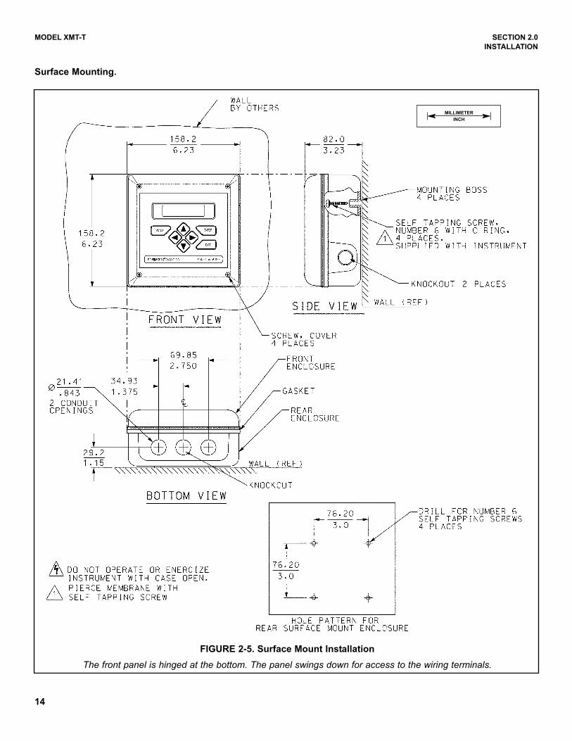
Surface/Pipe (code -11): 6.23 x 6.23 x 3.23 in. (158x 158 x 82 mm); see page 15 for dimensions of pipemounting bracket.
Conduit openings: Accepts PG13.5 or 1/2 in. conduit fit-tings
Ambient Temperature: 32 to 122°F (0 to 50°C). Somedegradation of display above 50°C.
Storage Temperature: -4 to 158°F (-20 to 70°C)
Relative Humidity: 10 to 90% (non-condensing)
Weight/Shipping Weight: 2 lb/3 lb (1 kg/1.5 kg)
Display: Two line, 16-character display. Character height:
4.8 mm; first line shows process variable, second line
shows process temperature and output current. Fault
and warning messages, when triggered, alternate with
temperature and output readings.
During calibration and programming, messages,
prompts, and editable values appear on the two-line
display.
Temperature resolution: 0.1°C (≤99.9°C);
1°C (≥100°C)
Hazardous Location Approval: For details, see specifi-
cations for the measurement of interest.
RFI/EMI: EN-61326
DIGITAL COMMUNICATIONS:
HART —
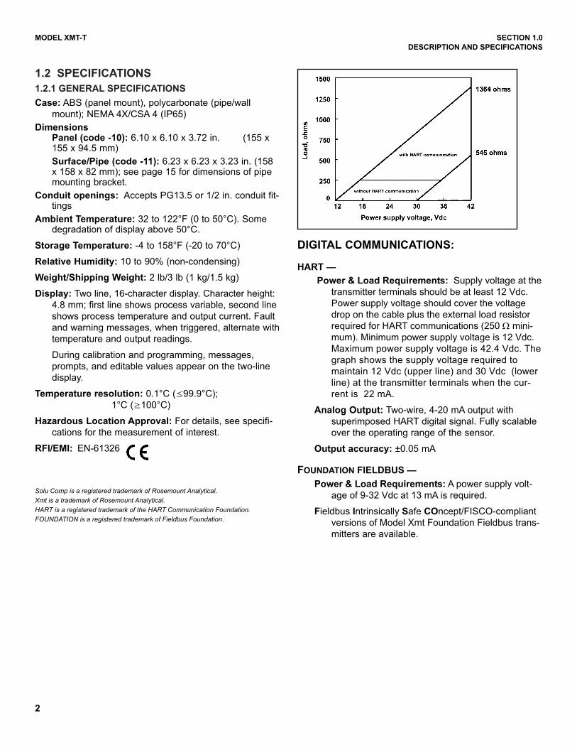
Power & Load Requirements: Supply voltage at the
transmitter terminals should be at least 12 Vdc.
Power supply voltage should cover the voltage
drop on the cable plus the external load resistor
required for HART communications (250 Ω mini-
mum). Minimum power supply voltage is 12 Vdc.
Maximum power supply voltage is 42.4 Vdc. The
graph shows the supply voltage required to
maintain 12 Vdc (upper line) and 30 Vdc (lower
line) at the transmitter terminals when the cur-
rent is 22 mA.
Analog Output: Two-wire, 4-20 mA output with
superimposed HART digital signal. Fully scalable
over the operating range of the sensor.
Output accuracy: ±0.05 mA
FOUNDATION FIELDBUS —
Power & Load Requirements: A power supply volt-
age of 9-32 Vdc at 13 mA is required.
Fieldbus Intrinsically Safe COncept/FISCO-compliant
versions of Model Xmt Foundation Fieldbus trans-
mitters are available.
Solu Comp is a registered trademark of Rosemount Analytical.Xmt is a trademark of Rosemount Analytical.HART is a registered trademark of the HART Communication Foundation. FOUNDATION is a registered trademark of Fieldbus Foundation.
3
MODEL XMT-T SECTION 1.0
DESCRIPTION AND SPECIFICATIONS
3
1.2.2 FUNCTIONAL SPECIFICATIONS
Automatic Temperature Compensation:
3-wire Pt 100 RTD or Pt 1000 RTD
Conductivity: 0 to 200°C (32 to 392°F)
% Concentration: 0 to 100°C (32 to 212°F)
Diagnostics: The internal diagnostics can detect:
Calibration Error ROM Failure
Temperature Slope Error Zero Error
High Temperature Warning CPU Failure
Low Temperature Warning Input Warning
Once one of the above is diagnosed, the LCD will display
a message describing the problem.
Digital Communications:
HART: PV, SV, and TV assignable to measurement
(conductivity, resistivity, or concentration), tempera-
ture, and raw conductivity. Raw conductivity is meas-
ured conductivity before temperature correction.
Fieldbus: Three AI blocks assignable to measurement
(conductivity, resistivity, or concentration), tempera-
ture, and raw conductivity. Raw conductivity is meas-
ured conductivity before temperature correction.
Execution time 75 msec. One PID block; execution
time 150 msec. Device type: 4084. Device revision: 1.
Certified to ITK 4.5.
1.2.3 TRANSMITTER SPECIFICATIONS @ 25°C
Measured Range: 50 to 2,000,000 µS/cm (see chart)
Repeatability: ± 0.25% of reading
Temperature Accuracy:
± 0.2°C between 0 and 50°C
± 0.5°C above 50°C
(excludes inaccuracies in sensor)
Temperature Slope Adjustment: 0-5%/° C
% Concentration Ranges:
Sodium Hydroxide: 0 to 12%
Hydrochloric Acid: 0 to 15%
Sulfuric Acid: 0 to 25% and 96.0 to 99.7%
Sodium Chloride: 0 to 20%
Ambient Temperature Coefficient:
± 0.1% of reading ±2µS/cm per °C
Maximum Cable Length: 100 ft (30 m)
1.2.4 LOOP SPECIFICATIONS
Loop Accuracy: With a standard Model 228 or 225 sen-
sor with 20' cable, following a single point calibration,
laboratory accuracy at 25°C can be as good as ±2% of
reading and ±50 µS/cm.
For optimum performance, standardize the sensor in
the process at the conductivity and temperature of
interest.
Results under real process conditions, at different tem-peratures, or using other sensors may differ fromabove.
Calibration: Calibrate against previously calibrated stan-
dard sensor and analyzer, or calibrate against solution
of known conductivity.
RECOMMENDED SENSORS:
Model 222 Flow-Through
Model 225 Clean-In-Place (CIP)
Model 226 Submersion/Insertion
Model 228 Submersion/Insertion/Retractable
Model 242 Flow-Through
Model 245 Sanitary Flow-Through
Model 247 Submersion/Flow-Tee

4
MODEL XMT-T SECTION 1.0
DESCRIPTION AND SPECIFICATIONS
1.3 HAZARDOUS LOCATION APPROVALS
Intrinsic Safety:
Class I, II, III, Div. 1
Groups A-G
T4 Tamb = 50°C
Class I, II, III, Div. 1
Groups A-G
T4 Tamb = 50°C
ATEX 1180
II 1 G
Baseefa04ATEX0215X
EEx ia IIC T4
Tamb = 0°C to 50°C
Non-Incendive:
Class I, Div. 2, Groups A-D
Dust Ignition Proof
Class II & III, Div. 1, Groups E-G
NEMA 4/4X Enclosure
Class I, Div. 2, Groups A-D
Dust Ignition Proof
Class II & III, Div. 1, Groups E-G
NEMA 4/4X Enclosure
T4 Tamb = 50°C
MODEL XMT-T SECTION 1.0
DESCRIPTION AND SPECIFICATIONS
FIG
UR
E 1
-1.
ME
NU
TR
EE
FO
R M
OD
EL
SO
LU
CO
MP
XM
T-T
-HT
TR
AN
SM
ITT
ER
1.4 MENU TREE FOR MODEL Xmt-T-HT
55
MODEL XMT-T SECTION 1.0
DESCRIPTION AND SPECIFICATIONS
FIG
UR
E 1
-2.
ME
NU
TR
EE
FO
R M
OD
EL
SO
LU
CO
MP
XM
T-T
-FF
TR
AN
SM
ITT
ER
1.5 MENU TREE FOR MODEL Xmt-T-FF
6
7
MODEL XMT-T SECTION 1.0
DESCRIPTION AND SPECIFICATIONS
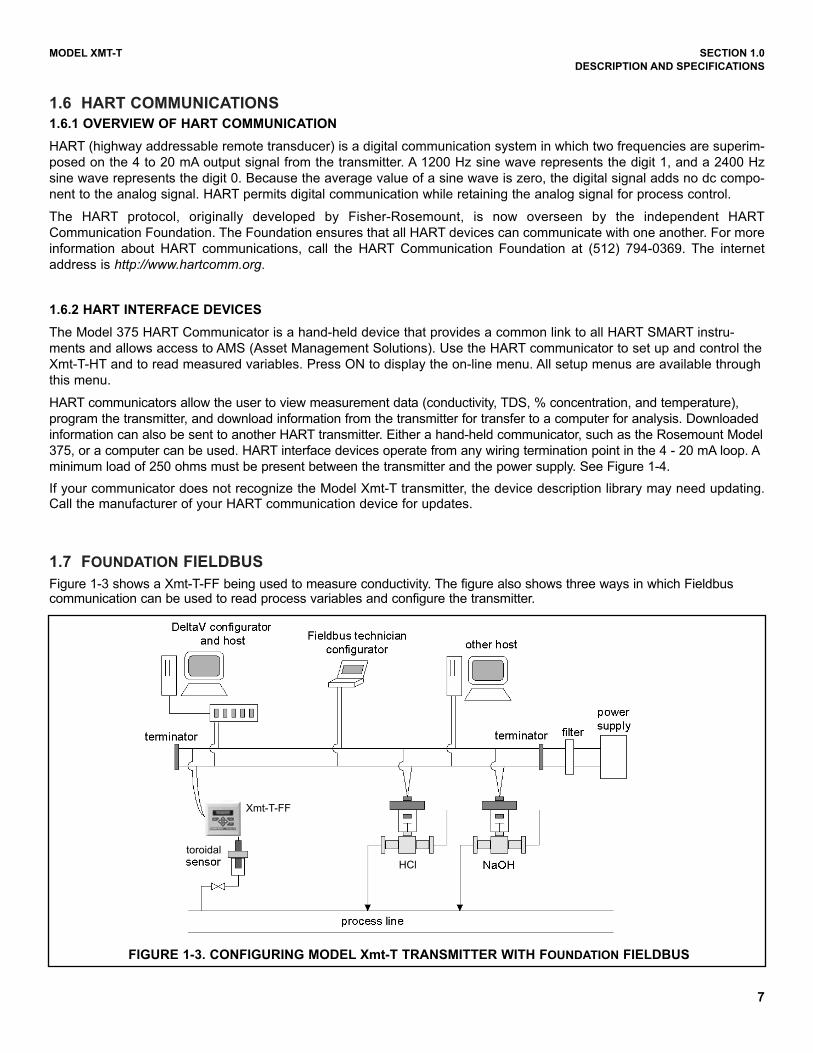
1.7 FOUNDATION FIELDBUS
Figure 1-3 shows a Xmt-T-FF being used to measure conductivity. The figure also shows three ways in which Fieldbuscommunication can be used to read process variables and configure the transmitter.
FIGURE 1-3. CONFIGURING MODEL Xmt-T TRANSMITTER WITH FOUNDATION FIELDBUS
1.6 HART COMMUNICATIONS
1.6.1 OVERVIEW OF HART COMMUNICATION
HART (highway addressable remote transducer) is a digital communication system in which two frequencies are superim-
posed on the 4 to 20 mA output signal from the transmitter. A 1200 Hz sine wave represents the digit 1, and a 2400 Hz
sine wave represents the digit 0. Because the average value of a sine wave is zero, the digital signal adds no dc compo-
nent to the analog signal. HART permits digital communication while retaining the analog signal for process control.
The HART protocol, originally developed by Fisher-Rosemount, is now overseen by the independent HART
Communication Foundation. The Foundation ensures that all HART devices can communicate with one another. For more
information about HART communications, call the HART Communication Foundation at (512) 794-0369. The internet
address is http://www.hartcomm.org.
1.6.2 HART INTERFACE DEVICES
The Model 375 HART Communicator is a hand-held device that provides a common link to all HART SMART instru-
ments and allows access to AMS (Asset Management Solutions). Use the HART communicator to set up and control the
Xmt-T-HT and to read measured variables. Press ON to display the on-line menu. All setup menus are available through
this menu.
HART communicators allow the user to view measurement data (conductivity, TDS, % concentration, and temperature),
program the transmitter, and download information from the transmitter for transfer to a computer for analysis. Downloaded
information can also be sent to another HART transmitter. Either a hand-held communicator, such as the Rosemount Model
375, or a computer can be used. HART interface devices operate from any wiring termination point in the 4 - 20 mA loop. A
minimum load of 250 ohms must be present between the transmitter and the power supply. See Figure 1-4.
If your communicator does not recognize the Model Xmt-T transmitter, the device description library may need updating.Call the manufacturer of your HART communication device for updates.
Xmt-T-FF
toroidal
HCl
8
MODEL XMT-T SECTION 1.0
DESCRIPTION AND SPECIFICATIONS
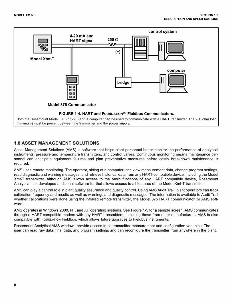
FIGURE 1-4. HART and FOUNDATION™ Fieldbus Communicators.
Both the Rosemount Model 375 (or 275) and a computer can be used to communicate with a HART transmitter. The 250 ohm load
(minimum) must be present between the transmitter and the power supply.
1.8 ASSET MANAGEMENT SOLUTIONS
Asset Management Solutions (AMS) is software that helps plant personnel better monitor the performance of analytical
instruments, pressure and temperature transmitters, and control valves. Continuous monitoring means maintenance per-
sonnel can anticipate equipment failures and plan preventative measures before costly breakdown maintenance is
required.
AMS uses remote monitoring. The operator, sitting at a computer, can view measurement data, change program settings,
read diagnostic and warning messages, and retrieve historical data from any HART-compatible device, including the Model
Xmt-T transmitter. Although AMS allows access to the basic functions of any HART compatible device, Rosemount
Analytical has developed additional software for that allows access to all features of the Model Xmt-T transmitter.
AMS can play a central role in plant quality assurance and quality control. Using AMS Audit Trail, plant operators can track
calibration frequency and results as well as warnings and diagnostic messages. The information is available to Audit Trail
whether calibrations were done using the infrared remote transmitter, the Model 375 HART communicator, or AMS soft-
ware.
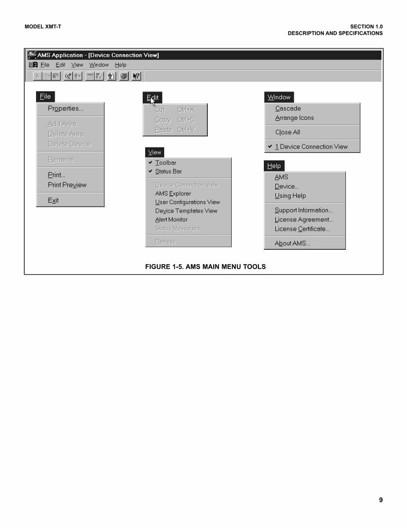
AMS operates in Windows 2000, NT, and XP operating systems. See Figure 1-5 for a sample screen. AMS communicates
through a HART-compatible modem with any HART transmitters, including those from other manufacturers. AMS is also
compatible with FOUNDATION Fieldbus, which allows future upgrades to Fieldbus instruments.
Rosemount Analytical AMS windows provide access to all transmitter measurement and configuration variables. The
user can read raw data, final data, and program settings and can reconfigure the transmitter from anywhere in the plant.
Model Xmt-T
MODEL XMT-T SECTION 1.0
DESCRIPTION AND SPECIFICATIONS
FIGURE 1-5. AMS MAIN MENU TOOLS
9
10
MODEL XMT-T SECTION 1.0
DESCRIPTION AND SPECIFICATIONS
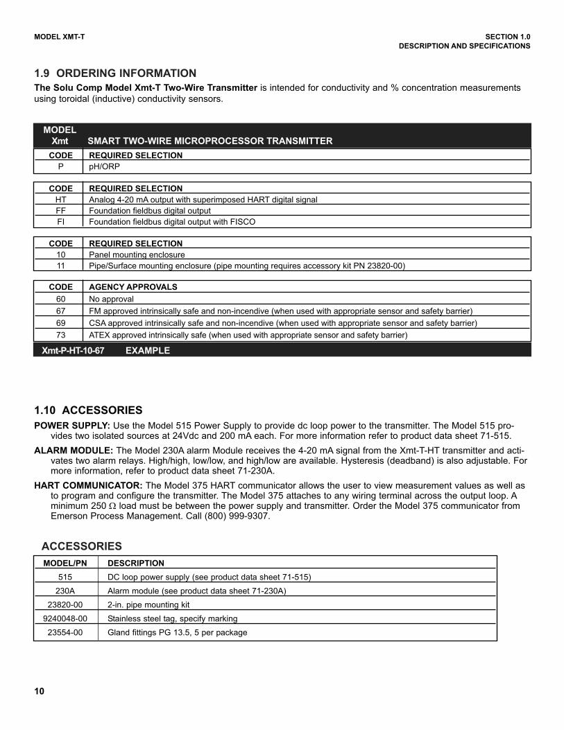
1.10 ACCESSORIES
POWER SUPPLY: Use the Model 515 Power Supply to provide dc loop power to the transmitter. The Model 515 pro-vides two isolated sources at 24Vdc and 200 mA each. For more information refer to product data sheet 71-515.
ALARM MODULE: The Model 230A alarm Module receives the 4-20 mA signal from the Xmt-T-HT transmitter and acti-vates two alarm relays. High/high, low/low, and high/low are available. Hysteresis (deadband) is also adjustable. Formore information, refer to product data sheet 71-230A.
HART COMMUNICATOR: The Model 375 HART communicator allows the user to view measurement values as well asto program and configure the transmitter. The Model 375 attaches to any wiring terminal across the output loop. Aminimum 250 Ω load must be between the power supply and transmitter. Order the Model 375 communicator fromEmerson Process Management. Call (800) 999-9307.
1.9 ORDERING INFORMATION
The Solu Comp Model Xmt-T Two-Wire Transmitter is intended for conductivity and % concentration measurements
using toroidal (inductive) conductivity sensors.
ACCESSORIES
MODEL/PN DESCRIPTION
515 DC loop power supply (see product data sheet 71-515)
230A Alarm module (see product data sheet 71-230A)
23820-00 2-in. pipe mounting kit
9240048-00 Stainless steel tag, specify marking
23554-00 Gland fittings PG 13.5, 5 per package
CODE REQUIRED SELECTION
HT Analog 4-20 mA output with superimposed HART digital signal
FF Foundation fieldbus digital output
FI Foundation fieldbus digital output with FISCO
CODE REQUIRED SELECTION
10 Panel mounting enclosure
11 Pipe/Surface mounting enclosure (pipe mounting requires accessory kit PN 23820-00)
CODE AGENCY APPROVALS
60 No approval
67 FM approved intrinsically safe and non-incendive (when used with appropriate sensor and safety barrier)
69 CSA approved intrinsically safe and non-incendive (when used with appropriate sensor and safety barrier)
73 ATEX approved intrinsically safe (when used with appropriate sensor and safety barrier)
CODE REQUIRED SELECTION
P pH/ORP
MODEL
Xmt SMART TWO-WIRE MICROPROCESSOR TRANSMITTER
Xmt-P-HT-10-67 EXAMPLE
11
MODEL XMT-T SECTION 2.0
INSTALLATION
SECTION 2.0INSTALLATION
2.1 Unpacking and Inspection
2.2 Installation
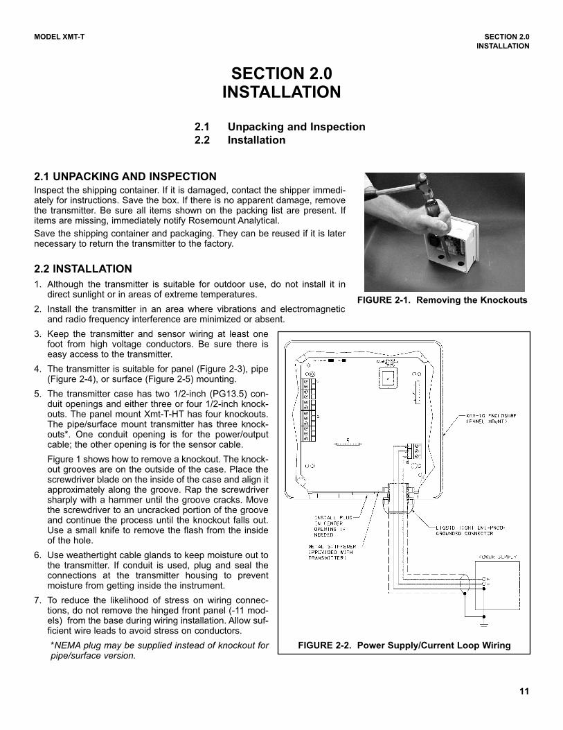
2.1 UNPACKING AND INSPECTIONInspect the shipping container. If it is damaged, contact the shipper immedi-ately for instructions. Save the box. If there is no apparent damage, removethe transmitter. Be sure all items shown on the packing list are present. Ifitems are missing, immediately notify Rosemount Analytical.
Save the shipping container and packaging. They can be reused if it is laternecessary to return the transmitter to the factory.
2.2 INSTALLATION
1. Although the transmitter is suitable for outdoor use, do not install it indirect sunlight or in areas of extreme temperatures.
2. Install the transmitter in an area where vibrations and electromagneticand radio frequency interference are minimized or absent.
3. Keep the transmitter and sensor wiring at least onefoot from high voltage conductors. Be sure there iseasy access to the transmitter.
4. The transmitter is suitable for panel (Figure 2-3), pipe(Figure 2-4), or surface (Figure 2-5) mounting.
5. The transmitter case has two 1/2-inch (PG13.5) con-duit openings and either three or four 1/2-inch knock-outs. The panel mount Xmt-T-HT has four knockouts.The pipe/surface mount transmitter has three knock-outs*. One conduit opening is for the power/outputcable; the other opening is for the sensor cable.
Figure 1 shows how to remove a knockout. The knock-out grooves are on the outside of the case. Place thescrewdriver blade on the inside of the case and align itapproximately along the groove. Rap the screwdriversharply with a hammer until the groove cracks. Movethe screwdriver to an uncracked portion of the grooveand continue the process until the knockout falls out.Use a small knife to remove the flash from the insideof the hole.
6. Use weathertight cable glands to keep moisture out tothe transmitter. If conduit is used, plug and seal theconnections at the transmitter housing to preventmoisture from getting inside the instrument.
7. To reduce the likelihood of stress on wiring connec-tions, do not remove the hinged front panel (-11 mod-els) from the base during wiring installation. Allow suf-ficient wire leads to avoid stress on conductors.
*NEMA plug may be supplied instead of knockout forpipe/surface version.
FIGURE 2-1. Removing the Knockouts
FIGURE 2-2. Power Supply/Current Loop Wiring
12
MODEL XMT-T SECTION 2.0
INSTALLATION
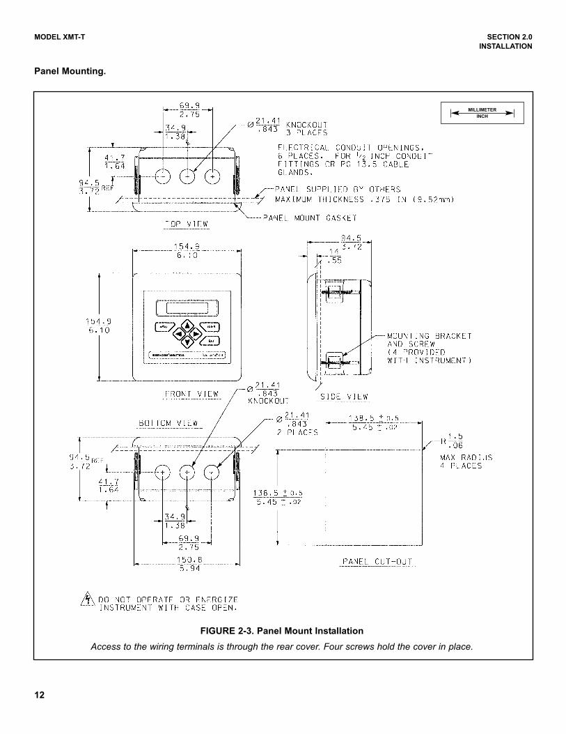
FIGURE 2-3. Panel Mount Installation
Access to the wiring terminals is through the rear cover. Four screws hold the cover in place.
Panel Mounting.
MILLIMETER
INCH
13
MODEL XMT-T SECTION 2.0
INSTALLATION
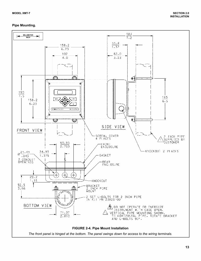
FIGURE 2-4. Pipe Mount Installation
The front panel is hinged at the bottom. The panel swings down for access to the wiring terminals.
Pipe Mounting.
MILLIMETER
INCH
14
MODEL XMT-T SECTION 2.0
INSTALLATION
FIGURE 2-5. Surface Mount Installation
The front panel is hinged at the bottom. The panel swings down for access to the wiring terminals.
Surface Mounting.
MILLIMETER
INCH
15
MODEL XMT-T SECTION 3.0
WIRING
3.1 POWER SUPPLY/CURRENT LOOP — MODEL Xmt-T-HT
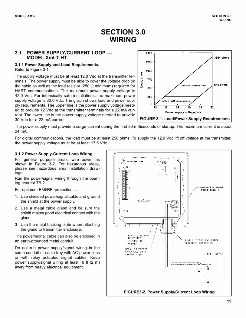
3.1.1 Power Supply and Load Requirements.
Refer to Figure 3-1.
The supply voltage must be at least 12.0 Vdc at the transmitter ter-
minals. The power supply must be able to cover the voltage drop on
the cable as well as the load resistor (250 Ω minimum) required for
HART communications. The maximum power supply voltage is
42.0 Vdc. For intrinsically safe installations, the maximum power
supply voltage is 30.0 Vdc. The graph shows load and power sup-
ply requirements. The upper line is the power supply voltage need-
ed to provide 12 Vdc at the transmitter terminals for a 22 mA cur-
rent. The lower line is the power supply voltage needed to provide
30 Vdc for a 22 mA current.
The power supply must provide a surge current during the first 80 milliseconds of startup. The maximum current is about
24 mA.
For digital communications, the load must be at least 250 ohms. To supply the 12.0 Vdc lift off voltage at the transmitter,
the power supply voltage must be at least 17.5 Vdc.
FIGURE 3-1. Load/Power Supply Requirements
FIGURE3-2. Power Supply/Current Loop Wiring
3.1.2 Power Supply-Current Loop Wiring.
For general purpose areas, wire power asshown in Figure 3-2. For hazardous areas,please see hazardous area installation draw-ings.
Run the power/signal wiring through the open-ing nearest TB-2.
For optimum EMI/RFI protection . . .
1. Use shielded power/signal cable and ground
the shield at the power supply.
2. Use a metal cable gland and be sure the
shield makes good electrical contact with the
gland.
3. Use the metal backing plate when attaching
the gland to transmitter enclosure.
The power/signal cable can also be enclosed in
an earth-grounded metal conduit.
Do not run power supply/signal wiring in the
same conduit or cable tray with AC power lines
or with relay actuated signal cables. Keep
power supply/signal wiring at least 6 ft (2 m)
away from heavy electrical equipment.
SECTION 3.0WIRING
16
MODEL XMT-T SECTION 3.0
WIRING
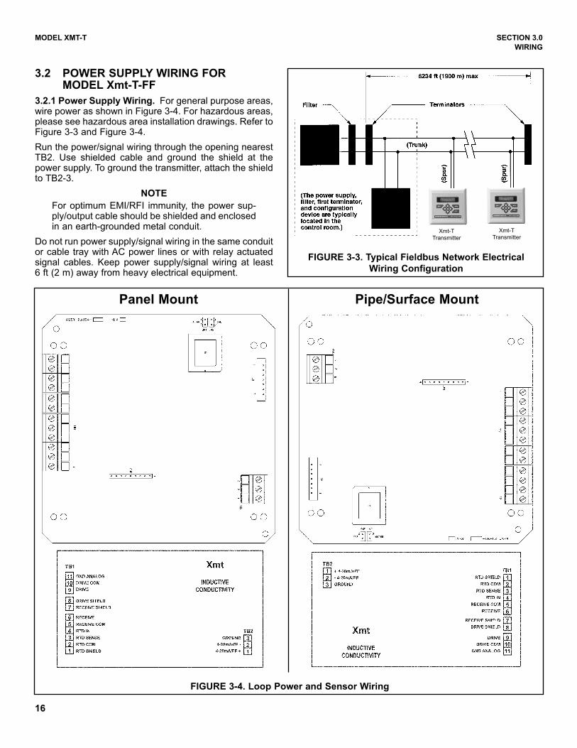
3.2 POWER SUPPLY WIRING FOR MODEL Xmt-T-FF
3.2.1 Power Supply Wiring. For general purpose areas,wire power as shown in Figure 3-4. For hazardous areas,please see hazardous area installation drawings. Refer toFigure 3-3 and Figure 3-4.
Run the power/signal wiring through the opening nearestTB2. Use shielded cable and ground the shield at thepower supply. To ground the transmitter, attach the shieldto TB2-3.
NOTE
For optimum EMI/RFI immunity, the power sup-ply/output cable should be shielded and enclosedin an earth-grounded metal conduit.
Do not run power supply/signal wiring in the same conduitor cable tray with AC power lines or with relay actuatedsignal cables. Keep power supply/signal wiring at least6 ft (2 m) away from heavy electrical equipment.
FIGURE 3-3. Typical Fieldbus Network Electrical
Wiring Configuration
Xmt-T
Transmitter
Xmt-T
Transmitter
FIGURE 3-4. Loop Power and Sensor Wiring
Panel Mount Pipe/Surface Mount
17
MODEL XMT-T SECTION 3.0
WIRING
3.3 SENSOR WIRING
Keep sensor wiring separate from power wiring. For best EMI/RFI protection, use shielded output signal cable in an
earth-grounded metal conduit. See Figure 3-4. Refer to the Instruction Sheet provided with each sensor for specific
wiring instructions.
3.1.1 WIRING THROUGH A JUNCTION BOX
The sensor can be wired to the analyzer through a remote junction box (PN 23550-00). Wire the extension cable and sen-
sor cable point-to-point. See Figure 3-4. Refer to the sensor instruction manual for more details.
Factory-terminated (PN 23294-05) and unterminated (PN 9200276) connecting cable are available. The use of factory-ter-
minated cable is strongly recommended. To prepare unterminated cable for use, follow the instructions in the sensor
instruction manual.
For maximum EMI/RFI protection, the outer braid of the sensor cable should be connected to the outer braided shield of
the extension cable. At the instrument, connect the outer braid of the extension cable to earth ground.
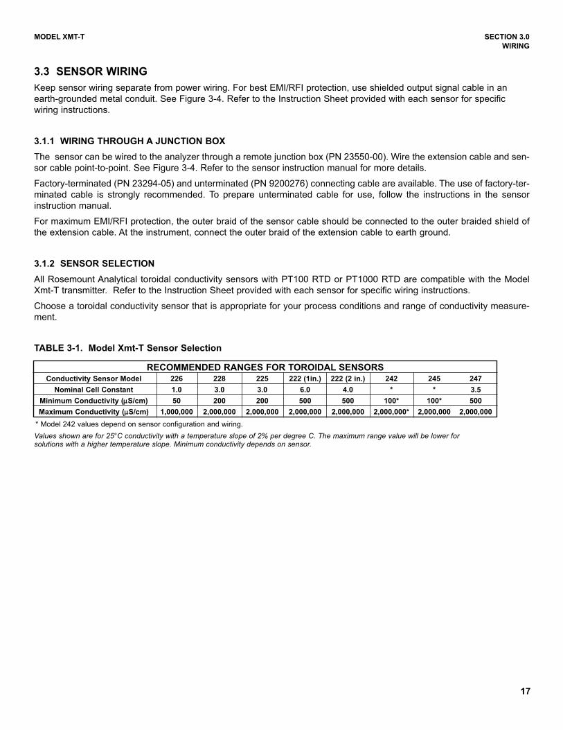
3.1.2 SENSOR SELECTION
All Rosemount Analytical toroidal conductivity sensors with PT100 RTD or PT1000 RTD are compatible with the Model
Xmt-T transmitter. Refer to the Instruction Sheet provided with each sensor for specific wiring instructions.
Choose a toroidal conductivity sensor that is appropriate for your process conditions and range of conductivity measure-
ment.
TABLE 3-1. Model Xmt-T Sensor Selection
Values shown are for 25°C conductivity with a temperature slope of 2% per degree C. The maximum range value will be lower forsolutions with a higher temperature slope. Minimum conductivity depends on sensor.
RECOMMENDED RANGES FOR TOROIDAL SENSORSConductivity Sensor Model 226 228 225 222 (1in.) 222 (2 in.) 242 245 247
Nominal Cell Constant 1.0 3.0 3.0 6.0 4.0 * * 3.5
Minimum Conductivity (µµS/cm) 50 200 200 500 500 100* 100* 500
Maximum Conductivity (µµS/cm) 1,000,000 2,000,000 2,000,000 2,000,000 2,000,000 2,000,000* 2,000,000 2,000,000
* Model 242 values depend on sensor configuration and wiring.
18
MODEL XMT-T SECTION 4.0
INTRINSICALLY SAFE INSTALLATION
SECTION 4.0INTRINSICALLY SAFE INSTALLATION
FIG
UR
E 4
-1.
FM
In
trin
sic
ally S
afe
Lab
el
for
Mo
del
Xm
t-T-H
T
19
FIG
UR
E 4
-2.
FM
In
trin
sic
ally S
afe
In
sta
llati
on
fo
r M
od
el
Xm
t-T-H
T
20
FIG
UR
E 4
-3.
CS
AIn
trin
sic
ally S
afe
Lab
el
for
Mo
del
Xm
t-T-H
T
21
FIG
UR
E 4
-4.
CS
AIn
trin
sic
ally S
afe
In
sta
llati
on
fo
r M
od
el
Xm
t-T-H
T
22
FIG
UR
E 4
-5. A
TE
X I
ntr
insic
ally S
afe
Lab
el
for
Mo
del
Xm
t-T-H
T
23
FIG
UR
E 4
-6. A
TE
X I
ntr
insic
ally S
afe
In
sta
llati
on
fo
r M
od
el
Xm
t-T-H
T

24
FIG
UR
E 4
-7.
FM
In
trin
sic
ally S
afe
Lab
el
for
Mo
del
Xm
t-T-F
F
10
/6
/ 0
4 J
. F
LO
CK
°CT
4
T
am
b =
50
SE
E B
LA
NK
LA
BE
L P
N 9
24
14
06
-01
.S
UP
ER
PR
EM
IUM
BLA
CK
TH
ER
MA
L T
RA
NS
FE
R R
IBB
ON
)N
OM
EN
CL
AT
UR
E T
O B
E P
RIN
TE
D U
SIN
G I
NT
ER
ME
CP
RE
SS
UR
E S
EN
SIT
IVE
AC
RY
LIC
AD
HE
SIV
E.
PN
L72
11210, 2 M
IL G
LO
SS
WH
ITE
PO
LY
ES
TE
R W
ITH
F
AR
SID
E A
ND
SP
LIT
LIN
ER
) O
R (
INT
ER
ME
C T
HIC
KN
ES
S.
PR
ES
SU
RE
SE
NS
ITIV
E A
DH
ES
IVE
, M
YL
AR
OV
ER
LA
MI N
AT
E,
.00
2-.
00
5 F
INIS
H ( .
00
2 R
EF
ER
EN
CE
TH
I CK
NE
SS
CL
EA
R M
AT
TE
( W
HIT
E V
INY
L F
AC
ES
TO
CK
) O
R P
OL
YE
ST
ER
,2
MA
TE
RIA
L: 3
M S
CO
TC
HC
AL #
3650
-10
9241
568 -
00/A
Ro
se
mo
un
t
An
aly
tica
lR
FM
AP
PR
OV
ED
INT
RIN
SIC
AL
LY
SA
FE
FO
R C
LA
SS
I,
II &
III
, D
IVIS
ION
1,
GR
OU
PS
A,
B,
C,
D,
E,
F &
G
HA
ZA
RD
OU
S A
RE
A W
HE
NC
ON
NE
CT
ED
PE
R D
WG
. 1
40
024
8
NO
N-I
NC
EN
DIV
E C
LA
SS
I,
DIV
ISIO
N 2
GR
OU
PS
A,
B,
C &
D
DU
ST
IG
NIT
ION
PR
OO
F C
LA
SS
II
AN
D I
II,
DIV
ISIO
N 1
,
GR
OU
PS
E,
F &
G
WA
RN
ING
: C
OM
PO
NE
NT
SU
BS
TIT
UT
ION
MA
Y I
MP
AIR
IN
TR
INS
IC
SA
FE
TY
OR
SU
ITA
BIL
ITY
FO
R D
IVIS
ION
2
NE
MA
4/4
X E
NC
LO
SU
RE
SU
PP
LY
9
-32
VD
C @
22 m
A
MO
DE
L
XM
T-T
-FF
-67
4.
N
OC
HA
NG
E W
ITH
OU
T F
M A
PP
RO
VA
L.
XM
T-T
-FF
LA
BE
L,
I.S
. F
M2
4X
R .
06
0
1.5
0
2.5
0
1.
A
RT
WO
RK
IS
SH
EE
T 2
OF
2.
M
ED
IUM
. B
AC
KG
RO
UN
D T
O B
E W
HIT
E.
O
N L
AB
EL
TO
BE
BL
AC
K H
EL
VE
TIC
A3.
A
LL A
LP
HA
AN
D N
UM
ER
IC C
HA
RA
CT
ER
S
Irvin
e, C
A 9
2606
2400
Bar
ranc
a P
kwy
Ros
emou
nt A
naly
tical
Div
isio
nE
mer
son
Pro
cess
Man
agem
ent,
Emer
son
10 /6 / 0
4
10/ 1/0
3N
OM
INA
L S
UR
FAC
E F
INIS
H 1
25
10-6
-04
9042
A
9241568-00
B. JO
HN
SO
N
J. F
LO
CK
2:1
A9
24
15
68
- 00
12
SH
EE
T
OF
06- 0
1
TOLE
RA
NC
ES
UN
LE
SS
OT
HE
RW
ISE
SP
EC
IFIE
D
AN
GLE
S+
1/2
-.0
30.X
X
.XX
X.0
10+-+
AP
PR
OV
AL
S
TIT
LE
B
DA
TE
TH
IS D
WG
CO
NV
ER
TE
D T
O
SO
LID
ED
GE
B
to th
ose
who
may
com
pete
with
Ros
emou
ntA
naly
tical
.R
osem
ount
Ana
lytic
al, a
nd is
not
to b
e m
ade
avai
labl
eTh
is d
ocum
ent c
onta
ins
info
rmat
ion
prop
rieta
ry to
CH
KD
ATE
BY
DE
SC
RIP
TIO
N
RE
VIS
ION
S
EC
OLT
R
RE
LEA
SE
DA
TEE
CO
NO
RE
V
NO
TE
S:
UN
LE
SS
OT
HE
RW
ISE
SP
EC
IFIE
D
EN
GR
AP
VD
PR
OJE
CT
CH
EC
KE
D
DR
AW
N
FIN
ISH
MA
TE
RIA
L
BIL
L O
F M
AT
ER
IAL
DW
G N
OR
EV
SIZ
E
SC
ALE
QT
YD
ES
CR
IPT
ION
PA
RT
NO
ITE
M
-
MA
CH
INE
D F
ILLE
T R
AD
II .0
20 M
AX
RE
MO
VE
BU
RR
S &
SH
AR
P E
DG
ES
.020
MA
XD
IME
NS
ION
S A
RE
IN IN
CH
ES
TH
IS D
OC
UM
EN
T I
S
CE
RT
IFIE
D B
Y
RE
V
RE
V
RE
V
RE
V
RE
V
RE
V
REV
ISIO
NS
NO
T PE
RM
ITTE
D
W/O
AG
ENC
Y AP
PRO
VAL
NO
RM
AL
OP
ER
AT
ING
TE
MP
ER
AT
UR
E R
AN
GE
: 0
-50vC
FM
A
25
FIG
UR
E 4
-8.
FM
In
trin
sic
ally S
afe
In
sta
llati
on
fo
r M
od
el
Xm
t-T-F
F
10/6/04
J.FL
OCK
11.M
ETA
L C
ON
DU
ITIS
NO
T R
EQ
UIR
ED
BU
T IF
US
ED
BO
ND
ING
BE
TWE
EN
CO
ND
UIT
IS N
OT
AU
TOM
ATI
C A
ND
MU
STB
E P
RO
VID
ED
AS
PA
RT
OF
THE
INS
TALL
ATI
ON
.
Po;
Isc,
It O
R lo
;V
oc, V
tOR
Uo;
Li+
Lcab
le.
Ci+
Cca
ble;
Pm
ax O
R P
i I
max
OR
Ii V
max
OR
Ui
FIE
LD D
EV
ICE
INP
UT
AS
SO
CIA
TED
AP
PA
RA
TUS
OU
TPU
TW
ITH
AS
SO
CIA
TED
AP
PA
RA
TUS
WH
EN
TH
E F
OLL
OW
ING
IS T
RU
E:
6. T
HE
INTR
INS
ICA
LLY
SA
FE E
NTI
TYC
ON
CE
PT
ALL
OW
S IN
TER
CO
NN
EC
TIO
N O
F IN
TRIN
SIC
ALL
Y S
AFE
DE
VIC
ES
La, L
t OR
Lo
Ca,
Ct O
R C
o
IND
UC
TAN
CE
(La)
WH
ICH
CA
N B
ES
AFE
LY C
ON
NE
CTE
D T
OTH
E A
PP
AR
ATU
S. (
RE
F. T
AB
LE I)
.
& 2
4522
2, 2
25, 2
26, 2
28,
SE
NS
OR
SA
PP
RO
VE
D C
ON
DU
CTI
VIT
Y
10. N
O R
EV
ISIO
N T
O D
RA
WIN
GW
ITH
OU
T P
RIO
R F
MA
PP
RO
VA
L.
9.TH
E A
SS
OC
IATE
D A
PP
AR
ATU
S M
US
T B
E F
MA
PP
RO
VE
D.
WH
EN
INS
TALL
ING
TH
ISE
QU
IPM
EN
T.7.
AS
SO
CIA
TED
AP
PA
RA
TUS
MA
NU
FAC
TUR
ER
'S IN
STA
LLA
TIO
N D
RA
WIN
GM
US
T B
E F
OLL
OW
ED
(SE
E T
AB
LE I)
TAB
LE I
Pm
axN
OT
GR
EA
TER
TH
AN
0.9
W Is
c O
R It
NO
TG
RE
ATE
R T
HA
N 2
00m
A V
oc O
R V
tNO
TG
RE
ATE
R T
HA
N 3
0 V
SU
PP
LY/S
IGN
AL
TER
MIN
ALS
TB
2-1,
2 A
ND
3.
1. A
NY
SIN
GLE
SH
UN
T ZE
NE
R D
IOD
E S
AFE
TY B
AR
RIE
R A
PP
RO
VE
D B
Y FM
HA
VIN
G T
HE
FO
LLO
WIN
G O
UTP
UT
PA
RA
ME
TER
S:
2.IN
TRIN
SIC
ALL
Y S
AFE
AP
PA
RA
TUS
(MO
DE
LXM
T-T-
FF, I
RC
TR
AN
SM
ITTE
R A
ND
MO
DE
L 37
5)
XMTR
XMT-
T-FF
MO
DE
L
XMT-
T-FF
XMT-
T-FF
EN
TITY
PA
RA
ME
TER
S
(FM
AP
PR
OV
ALS
)M
OD
XM
T-T-
FF X
MTR
0.0
SU
PP
LY /
SIG
NA
LTE
RM
INA
LS T
B2-
1, 2
AN
D 3
3 2 1
23456789101112 1
(SE
E N
OTE
S 1
& 9
)S
AFE
TY B
AR
RIE
R
300
30
SYS
TEM
S F
OR
HA
ZAR
DO
US
(CLA
SS
IFIE
D) L
OC
ATI
ON
S" A
ND
TH
E N
ATI
ON
AL
ELE
CTR
ICA
L C
OD
E (A
NS
I/NFP
A 7
0) S
EC
TIO
NS
504
AN
D 5
05.
3. IN
STA
LLA
TIO
N S
HO
ULD
BE
IN A
CC
OR
DA
NC
E W
ITH
AN
SI/I
SA
RP
12.0
6.01
"IN
STA
LLA
TIO
N O
FIN
TRIN
SIC
ALL
YS
AFE
0.4
MO
DE
L N
O.
00.
9V
max
(Vdc
)Li
(mH
)C
i (nF
)P
max
(W)
Imax
(mA
)
0.0
321.
9
EN
TITY
PA
RA
ME
TER
S: R
EM
OTE
TRA
NS
MIT
TER
INTE
RFA
CE
Isc
max
OU
T:uA
Voc
max
OU
T: V
dcPa
mx
IN: W
Imax
IN:m
AV
max
IN: V
dc37
5M
OD
EL
NO
.1.
020
030
Li (m
H)
Ci (
uF)
FIE
LD C
OM
MU
NIC
ATO
RR
OS
EM
OU
NT
MO
DE
L 37
5
CLA
SS
I A
RE
AO
NLY
INTE
RFA
CE
FO
R U
SE
INR
EM
OTE
TR
AN
SM
ITTE
R
SU
ITA
BIL
ITY
FOR
DIV
ISIO
N 2
.S
UB
STI
TUTI
ON
OF
CO
MP
ON
EN
TS M
AY
IMP
AIR
INTR
INS
IC S
AFE
TY O
R
DIS
CO
NN
EC
T P
OW
ER
BE
FOR
E S
ER
VIC
ING
.TO
PR
EV
EN
T IG
NIT
ION
OF
FLA
MM
AB
LE O
R C
OM
BU
STI
BLE
ATM
OS
PH
ER
ES
,
G
RO
UP
S A
, B, C
, D, E
, F, G
;
DIV
ISIO
N 1
,IS
CLA
SS
I, II
, III,
HAZ
ARD
OU
S A
RE
A
WA
RN
ING
-
INC
LUD
ING
INTE
RC
ON
NE
CTI
NG
WIR
ING
, MU
ST
BE
EQ
UA
LO
R L
ES
S T
HA
N T
HE
CA
PA
CIT
AN
CE
(Ca)
AN
D U
NP
RO
TEC
TED
CA
PA
CIT
AN
CE
(Ci)
AN
D IN
DU
CTA
NC
E (L
i) O
FTH
E IN
TRIN
SIC
ALL
Y S
AFE
AP
PA
RA
TUS
, D
ELI
VE
RE
D B
YTH
E A
SS
OC
IATE
D A
PP
AR
ATU
S (S
AFE
TYB
AR
RIE
R).
IN A
DD
ITIO
N,T
HE
MA
XIM
UM
EQ
UA
LTO
OR
GR
EA
TER
TH
AN
TH
EV
OLT
AG
E (V
oc O
R V
t) A
ND
CU
RR
EN
T (Is
c O
R It
) WH
ICH
CA
N B
ETH
E V
OLT
AG
E (V
max
) AN
D C
UR
RE
NT
(Imax
) OF
THE
INTR
INS
ICA
LLY
SA
FE A
PP
AR
ATU
S M
US
T B
EA
ND
AS
SO
CIA
TED
AP
PA
RA
TUS
(SA
FETY
BA
RR
IER
) SH
ALL
ME
ET
THE
FO
LLO
WIN
G R
EQ
UIR
EM
EN
TS:
24V
TYP
30 V
DC
MA
X FO
R IS
PO
WE
R S
UP
PLY
UN
SP
EC
IFIE
D
5. R
ES
ISTA
NC
E B
ETW
EE
N IN
TRIN
SIC
ALL
YS
AFE
GR
OU
ND
AN
D E
AR
TH G
RO
UN
D M
US
TB
E L
ES
STH
AN
1.0
Ohm
.
4. D
US
T-TI
GH
T C
ON
DU
IT S
EA
L M
US
TB
E U
SE
D W
HE
N IN
STA
LLE
D IN
CLA
SS
IIA
ND
CLA
SS
III E
NV
IRO
NM
EN
TS.
WA
RN
ING
-
NO
N-H
AZAR
DO
US
AR
EA
LOA
D
MO
RE
TH
AN
250
Vrm
s O
R V
dc.
8. C
ON
TRO
L E
QU
IPM
EN
T C
ON
NE
CTE
D T
O A
SS
OC
IATE
D A
PP
AR
ATU
S M
US
T N
OT
US
EO
R G
EN
ER
ATE
10/6/04
B. JO
HNSO
N
THIS
DO
CU
MEN
T IS
CER
TIFI
ED
BY
RE
V
RE
V
RE
V
RE
V
RE
V
RE
V
REVIS
IONS
NOT
PERM
ITTED
W/O
AGEN
CYAP
PROV
AL
SC
HE
MAT
IC, I
NS
TALL
ATI
ON
Unilo
c 9/
15/04
NOMI
NAL S
URFA
CE F
INIS
H 12
5
A90
6410
-6-0
4
1400248
11
SHEE
TOF
NON E
J. F
LOCK
A14
0024
8
D
CD
C
B A
12
34
56
78
67
85
43
2
B A
10-9
6
1
D
APPR
OVAL
S.03
0.X
X.X
XX.01
0+ -
ANGL
ES+
1/2
-+-
TOLE
RANC
ES
SOLI
D ED
GE
CHK
REVI
SION
DATE
BYDE
SCRI
PTIO
NEC
OLT
R
NO
TES
: UN
LES
S O
THE
RW
ISE
SP
EC
IFIE
DRE
VEC
O NO
.RE
LEAS
E DA
TE
PART
NO.
ITEM
QTY
BILL
OF
MATE
RIAL
DESC
RIPT
ION
DATE
THIS
DW
GCO
NVER
TED
TO
DRAW
N
CHEC
KED
totho
se w
ho m
ayco
mpete
with
Rose
moun
tAna
lytica
l.Ro
semo
unt A
nalyt
ical, a
nd is
not to
be m
ade a
vaila
bleTh
isdo
cume
ntco
ntains
infor
matio
n pr
oprie
tary t
o
TYPE
SCAL
E
TITL
E
REV
DWG
NO.
SIZE
ENGR
APV
DPR
OJEC
T
MATE
RIAL
FINI
SH
MACH
INED
FILL
ET R
ADII .0
20 M
AXRE
MOVE
BUR
RS &
SHA
RP E
DGES
.020
MAX
DIME
NSIO
NS A
RE IN
INCH
ES
UN
LESS
OTH
ERW
ISE
SP
ECIF
IED
Ros
emou
nt A
naly
tical
,U
nilo
c D
ivis
ion
2400
Bar
ranc
a P
kwy
Irvin
e, C
A92
606
12. T
HE
LE
NG
TH O
FTH
E S
EN
SO
R C
AB
LE M
US
T N
OT
EXC
EE
D 2
50 F
EE
T.
FMA
26
FIG
UR
E 4
-9.
CS
AIn
trin
sic
ally S
afe
Lab
el
for
Mo
del
Xm
t-T-F
F
10
/6
/04
J. F
LO
CK
J. F
LO
CK
°CT
4
T
am
b =
50
9241
576-
00/A
Rosem
ount
Ana
lytical
R
INT
RIN
SIC
AL
LY
SA
FE
FO
R C
LA
SS
I,
II &
III
, D
IVIS
ION
1,
GR
OU
PS
A,
B,
C,
D,
E,
F &
G
HA
ZA
RD
OU
S A
RE
A W
HE
NC
ON
NE
CT
ED
PE
R D
WG
. 1
40
02
64
NO
N-I
NC
EN
DIV
E C
LA
SS
I,
DIV
ISIO
N 2
GR
OU
PS
A,
B,
C &
D
DU
ST
IG
NIT
ION
PR
OO
F C
LA
SS
II
AN
D I
II,
DIV
ISIO
N 1
,
GR
OU
PS
E,
F &
G
WA
RN
ING
: C
OM
PO
NE
NT
SU
BS
TIT
UT
ION
MA
Y I
MP
AIR
IN
TR
INS
IC
SA
FE
TY
OR
SU
ITA
BIL
ITY
FO
R D
IVIS
ION
2
NE
MA
4/4
X E
NC
LO
SU
RE
SU
PP
LY
9
-32
VD
C @
22 m
A
MO
DE
L
XM
T-T
-FF
-69
R-L
R 3
4186
SE
E B
LA
NK
LA
BE
L P
N 9
24
1406-0
1.
SU
PE
R P
RE
MIU
M B
LA
CK
TH
ER
MA
L T
RA
NS
FE
R R
IBB
ON
)N
OM
EN
CL
AT
UR
E T
O B
E P
RIN
TE
D U
SIN
G I
NT
ER
ME
CP
RE
SS
UR
E S
EN
SIT
IVE
AC
RY
LIC
AD
HE
SIV
E.
PN
L72
11210, 2 M
IL G
LO
SS
WH
ITE
PO
LY
ES
TE
R W
ITH
F
AR
SID
E A
ND
SP
LIT
LIN
ER
) O
R (
INT
ER
ME
C T
HIC
KN
ES
S. P
RE
SS
UR
E S
EN
SIT
IVE
AD
HE
SIV
E,
M
YLA
R O
VE
RLA
MIN
AT
E, .0
02-.
005 F
INIS
H
(.0
02
RE
FE
RE
NC
E T
HIC
KN
ES
S C
LE
AR
MA
TT
E
(WH
ITE
VIN
YL F
AC
ES
TO
CK
) O
R P
OLY
ES
TE
R,
2
MA
TE
RIA
L: 3M
SC
OT
CH
CA
L #
3650-1
0
4.
N
OC
HA
NG
E W
ITH
OU
T C
SA
AP
PR
OV
AL
.
LA
BE
L, I.S
. C
SA
XM
T-T
-FF
2
4X
R .060
1.5
0
2.5
0
1. A
RT
WO
RK
IS
SH
EE
T 2
OF
2.
ME
DIU
M.
BA
CK
GR
OU
ND
TO
BE
WH
ITE
. O
N L
AB
EL T
O B
E B
LA
CK
HE
LV
ET
ICA
3.
ALL A
LP
HA
AN
D N
UM
ER
IC C
HA
RA
CT
ER
S
Irvin
e, C
A 9
2606
2400
Bar
ranc
a P
kwy
Ros
emou
nt A
naly
tical
Div
isio
nE
mer
son
Pro
cess
Man
agem
ent,
Emer
son
10 /6/0
4
9/2
4/0
3N
OM
INA
L S
UR
FAC
E F
INIS
H 1
25
10-6
-04
9033
A
9241576-00
B.
JO
HN
SO
N
J. F
LO
CK
2:1
A9
24
15
76
-00
12
SH
EE
T
O
F06
-01
TOLE
RA
NC
ES
UN
LE
SS
OT
HE
RW
ISE
SP
EC
IFIE
D
AN
GLE
S+
1/2
-.0
30.X
X
.XX
X.0
10+-+
AP
PR
OV
AL
S
TIT
LE
B
DA
TE
TH
IS D
WG
CO
NV
ER
TE
D T
O
SO
LID
ED
GE
B
to th
ose
who
may
com
pete
with
Ros
emou
ntA
naly
tical
.R
osem
ount
Ana
lytic
al, a
nd is
not
to b
e m
ade
avai
labl
eTh
is d
ocum
ent c
onta
ins
info
rmat
ion
prop
rieta
ry to
CH
KD
ATE
BY
DE
SC
RIP
TIO
N
RE
VIS
ION
S
EC
OLT
R
RE
LEA
SE
DA
TEE
CO
NO
RE
V
NO
TE
S:
UN
LE
SS
OT
HE
RW
ISE
SP
EC
IFIE
D
EN
GR
AP
VD
PR
OJE
CT
CH
EC
KE
D
DR
AW
N
FIN
ISH
MA
TE
RIA
L
BIL
L O
F M
AT
ER
IAL
DW
G N
OR
EV
SIZ
E
SC
ALE
QT
YD
ES
CR
IPT
ION
PA
RT
NO
ITE
M
-
MA
CH
INE
D F
ILLE
T R
AD
II .0
20 M
AX
RE
MO
VE
BU
RR
S &
SH
AR
P E
DG
ES
.020
MA
XD
IME
NS
ION
S A
RE
IN IN
CH
ES
TH
IS D
OC
UM
EN
T I
S
CE
RT
IFIE
D B
Y
RE
V
RE
V
RE
V
RE
V
RE
V
RE
V
REV
ISIO
NS
NO
T PE
RM
ITTE
D
W/O
AG
ENC
Y AP
PRO
VAL
NO
RM
AL
OP
ER
AT
ING
TE
MP
ER
AT
UR
E R
AN
GE
: 0
-50vC
CS
AA
27
FIG
UR
E 4
-10.
CS
AIn
trin
sic
ally S
afe
In
sta
llati
on
fo
r M
od
el
Xm
t-T-F
F
10/06
/04J.
F LO C
K
10/0 6
/0 4J.
F LOC
K
HAZ
ARD
OU
S A
RE
A
C
LAS
S II
I
CLA
SS
II, G
RP
S E
-GIS
CLA
SS
I, G
RP
S A
-D
Po;
Isc,
It O
R lo
;V
oc, V
tOR
Uo;
9. T
HE
AS
SO
CIA
T ED
AP
PA
RA
TUS
MU
ST
BE
CS
A A
PP
RO
VE
D.
IND
UC
TAN
CE
(La)
WH
ICH
CA
N B
ES
AFE
LY C
ON
NE
CTE
D T
OTH
E A
PP
AR
ATU
S. (
RE
F.TA
BLE
I).
& 2
4522
2, 2
25, 2
26, 2
28,
SE
NS
OR
SA
PP
RO
VE
D C
ON
DU
CTI
VIT
Y
10. N
O R
EV
ISIO
N T
O D
RA
WIN
GW
ITH
OU
T P
RIO
R C
SA
AP
PR
OV
AL.
WH
EN
INS
TALL
ING
TH
ISE
QU
IPM
EN
T.7.
AS
SO
CIA
TED
AP
PA
RA
TUS
MA
NU
FAC
TUR
ER
'S IN
STA
LLA
TIO
N D
RA
WIN
G M
US
T B
E F
OLL
OW
ED
(SE
E T
AB
LE I)
TAB
LE I
Pm
axN
OT
GR
EA
TER
TH
AN
1.3
W Is
c O
R It
NO
TG
RE
ATE
R T
HA
N 3
00 m
A V
oc O
R V
tNO
TG
RE
ATE
R T
HA
N 3
0 V
SU
PP
LY/S
IGN
AL
TER
MIN
ALS
TB
2-1,
2 A
ND
3.
1. A
NY
SIN
GLE
SH
UN
T ZE
NE
R D
IOD
E S
AFE
TY B
AR
RIE
R A
PP
RO
VE
D B
Y C
SA
HA
VIN
GTH
E F
OLL
OW
ING
OU
TPU
TP
AR
AM
ETE
RS
:
2.IN
TRIN
SIC
ALL
Y S
AFE
AP
PA
RA
TUS
(MO
DE
L XM
T-T-
FF, I
RC
TR
AN
SM
ITTE
R A
ND
MO
DE
L 37
5)
XMTR
XMT-
T-FF
MO
DE
L
XMT-
T-FF
XMT-
T-FF
EN
TITY
PA
RA
ME
TER
S
0.0
SU
PP
LY /
SIG
NA
LTE
RM
INA
LS T
B2-
1, 2
AN
D 3
3 2 1
23456789101112 1
(SE
E N
OTE
S 1
& 9
)S
AFE
TY B
AR
RIE
R
Li+
Lcab
le.
Ci+
Cca
ble;
Pm
ax O
R P
iIm
ax O
RIi
Vm
ax O
R U
iFI
ELD
DE
VIC
E IN
PU
T A
SS
OC
IATE
D A
PP
AR
ATU
S O
UTP
UT
WIT
H A
SS
OC
IATE
D A
PP
AR
ATU
S W
HE
N T
HE
FO
LLO
WIN
G IS
TRU
E:
6.T
HE
INTR
INS
ICA
LLY
SA
FE E
NTI
TY C
ON
CE
PT
ALL
OW
S IN
TER
CO
NN
EC
TIO
N O
F IN
TRIN
SIC
ALL
Y S
AFE
DE
VIC
ES
300
30
La, L
t OR
Lo
Ca,
Ct O
R C
o
SYS
TEM
S F
OR
HA
ZAR
DO
US
(CLA
SS
IFIE
D) L
OC
ATI
ON
S" A
ND
TH
E C
AN
AD
IAN
ELE
CTR
ICA
L C
OD
E, C
SA
C22
.1, P
AR
T 1,
AP
PE
ND
IX F
.3.
INS
TALL
ATI
ON
SH
OU
LD B
E IN
AC
CO
RD
AN
CE
WIT
H A
NS
I/IS
A R
P12
.06.
01 "I
NS
TALL
ATI
ON
OF
INTR
INS
ICA
LLY
SA
FE
0.4
MO
DE
L N
O.
01.
3V
max
(Vdc
)Li
(mH
)C
i (nF
)P
max
(W)
Imax
(mA
)
0.0
321.
9
EN
TITY
PA
RA
ME
TER
S: R
EM
OTE
TRA
NS
MIT
TER
INTE
RFA
CE
Isc
max
OU
T:uA
Voc
max
OU
T: V
dcP
max
IN: W
Imax
IN:m
AV
max
IN: V
dc37
5M
OD
EL
NO
.1.
020
030
Li (m
H)
Ci (
uF)
FIE
LD C
OM
MU
NIC
ATO
RR
OS
EM
OU
NT
MO
DE
L 37
5
CLA
SS
I A
RE
AO
NLY
INTE
RFA
CE
FO
R U
SE
INR
EM
OTE
TR
AN
SM
ITTE
R
SU
ITA
BIL
ITY
FOR
DIV
ISIO
N 2
.S
UB
STI
TUTI
ON
OF
CO
MP
ON
EN
TS M
AY
IMP
AIR
INTR
INS
IC S
AFE
TY O
R
DIS
CO
NN
EC
T P
OW
ER
BE
FOR
E S
ER
VIC
ING
.TO
PR
EV
EN
T IG
NIT
ION
OF
FLA
MM
AB
LE O
R C
OM
BU
STI
BLE
ATM
OS
PH
ER
ES
,W
AR
NIN
G-
IN
CLU
DIN
G IN
TER
CO
NN
EC
TIN
G W
IRIN
G, M
US
T B
E E
QU
AL
OR
LE
SS
THA
N T
HE
CA
PA
CIT
AN
CE
(Ca)
AN
D U
NP
RO
TEC
TED
CA
PA
CIT
AN
CE
(Ci)
AN
D IN
DU
CTA
NC
E (L
i) O
FTH
E IN
TRIN
SIC
ALL
YS
AFE
AP
PA
RA
TUS
, D
ELI
VE
RE
D B
YTH
E A
SS
OC
IATE
D A
PP
AR
ATU
S (S
AFE
TYB
AR
RIE
R).
IN A
DD
ITIO
N,T
HE
MA
XIM
UM
EQ
UA
L TO
OR
GR
EA
TER
TH
AN
TH
EV
OLT
AG
E (V
oc O
R V
t) A
ND
CU
RR
EN
T (Is
c O
R It
) WH
ICH
CA
N B
ETH
E V
OLT
AG
E (V
max
) AN
D C
UR
RE
NT
(Imax
) OF
THE
INTR
INS
ICA
LLY
SA
FE A
PP
AR
ATU
S M
US
T B
E A
ND
AS
SO
CIA
TED
AP
PA
RA
TUS
(SA
FETY
BA
RR
IER
) SH
ALL
ME
ET
THE
FO
LLO
WIN
G R
EQ
UIR
EM
EN
TS:
24V
TYP
30 V
DC
MA
X FO
R IS
PO
WE
R S
UP
PLY
UN
SP
EC
IFIE
D
5. R
ES
ISTA
NC
E B
ETW
EE
N IN
TRIN
SIC
ALL
YS
AFE
GR
OU
ND
AN
D E
AR
TH G
RO
UN
D M
US
TB
E L
ES
S T
HA
N 1
.0 O
hm.
4. D
US
T-TI
GH
T C
ON
DU
IT S
EA
L M
US
TB
E U
SE
D W
HE
N IN
STA
LLE
D IN
CLA
SS
IIA
ND
CLA
SS
III E
NV
IRO
NM
EN
TS.
WA
RN
ING
-
NO
N-H
AZAR
DO
US
AR
EA
LOA
D
MO
RE
TH
AN
250
Vrm
sO
R V
dc.
8. C
ON
TRO
L E
QU
IPM
EN
T C
ON
NE
CTE
D T
OA
SS
OC
IATE
D A
PP
AR
ATU
S M
US
T N
OT
US
E O
R G
EN
ER
ATE
THIS
DO
CU
MEN
T IS
CER
TIFI
ED
BY
RE
V
RE
V
RE
V
RE
V
RE
V
RE
V
REVIS
IONS
NOT
PERM
ITTED
W/O
AGEN
CYAP
PROV
AL
(CS
A)
MO
D X
MT-
T-FF
XM
TR
B. JO
HNSO
NS
CH
EM
ATIC
, IN
STA
LLA
TIO
N
Unilo
c 9/
15/04
NOMI
NAL S
URFA
CE F
INIS
H 12
5
A90
4710
-6-0
4
1400264
11
SHEE
TOF
NONE
A14
0026
4
D
CD
C
B A
12
34
56
78
67
85
43
2
B A
10-9
6
1
D
APPR
OVAL
S.03
0.X
X.X
XX.01
0+ -
ANGL
ES+
1/2
-+-
TOLE
RANC
ES
SOLI
D ED
GE
CHK
REVI
SION
DATE
BYDE
SCRI
PTIO
NEC
OLT
R
NO
TES
: UN
LES
S O
THE
RW
ISE
SP
EC
IFIE
DRE
VEC
O NO
.RE
LEAS
E DA
TE
PART
NO.
ITEM
QTY
BILL
OF
MATE
RIAL
DESC
RIPT
ION
DATE
THIS
DW
GCO
NVER
TED
TO
DRAW
N
CHEC
KED
totho
se w
ho m
ayco
mpete
with
Rose
moun
tAna
lytica
l.Ro
semo
unt A
nalyt
ical, a
nd is
not to
be m
ade a
vaila
bleTh
isdo
cume
ntco
ntains
infor
matio
n pr
oprie
tary t
o
T YPE
SCAL
E
TITL
E
REV
DWG
NO.
SIZE
ENGR
APV
DPR
OJEC
T
MATE
RIAL
FINI
SH
MACH
INED
FILL
ET R
ADII .0
20 M
AXRE
MOVE
BUR
RS &
SHA
RP E
DGES
.020
MAX
DIME
NSIO
NS A
RE IN
INCH
ES
UN
LESS
OTH
ERW
ISE
SP
ECIF
IED
Ros
emou
nt A
naly
tical
,U
nilo
c D
ivis
ion
2400
Bar
ranc
a P
kwy
Irvin
e, C
A92
606
CS
AA
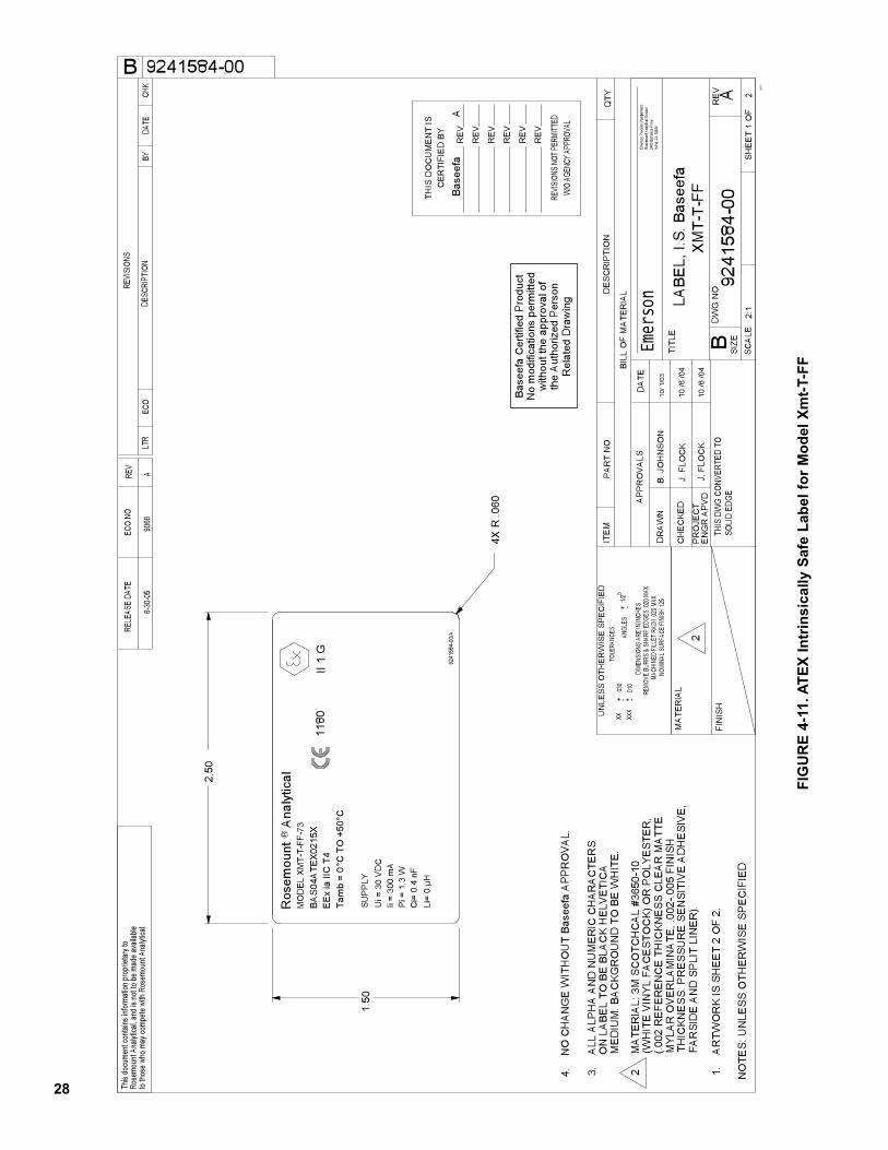
28
FIG
UR
E 4
-11. A
TE
X I
ntr
insic
ally S
afe
Lab
el
for
Mo
del
Xm
t-T-F
F
10 /6
/04
°C°C
TO
+50
Tam
b =
0
9241
584-
00/A
Ros
emou
nt
Ana
lytic
alR
SU
PP
LY
II 1
G11
80E
Ex ia
IIC
T4
BA
S04
ATE
X021
5X
Ui =
30
VD
CIi
= 30
0m
AP
i = 1
.3 W
MO
DE
L XM
T-T-
FF-7
3
Ci=
0.4
nF
Li=
0 µH
No
mod
ifica
tions
perm
itted
with
out t
he a
ppro
val o
fth
e A
utho
rized
Per
son
Rel
ated
Dra
win
g
Bas
eefa
Cer
tifie
d P
rodu
ct
4.
NO
CH
ANG
E W
ITH
OU
T B
asee
fa A
PPR
OV
AL.
LAB
EL,
I.S
. Bas
eefa
XMT-
T-FF
2
4XR
.060
1.50
2.50
1.
AR
TWO
RK
IS S
HE
ET
2 O
F 2.
F
ARSI
DE
AN
D S
PLI
T LI
NE
R).
T
HIC
KNE
SS.
PR
ES
SUR
E S
ENSI
TIV
E A
DH
ESI
VE
,
MY
LAR
OV
ERLA
MIN
ATE
, .00
2-.0
05 F
INIS
H
(.00
2 R
EFE
REN
CE
TH
ICKN
ES
S C
LEAR
MA
TTE
(W
HIT
E V
INY
L FA
CE
STO
CK)
OR
PO
LYE
STE
R,
2
MA
TER
IAL:
3M
SC
OTC
HC
AL
#365
0-10
M
ED
IUM
. BA
CKG
RO
UN
D T
O B
E W
HIT
E.
O
N L
AB
EL
TO B
E B
LAC
K H
ELV
ETI
CA
3.
ALL
ALP
HA
AN
D N
UM
ER
IC C
HAR
ACTE
RS
Irvine
, CA
9260
624
00 B
arra
nca P
kwy
Rose
moun
t Ana
lytica
l Divi
sion
Emer
son P
roce
ss M
anage
ment,
Emer
son
10 /6
/04
10/ 1
/03
NOMI
NAL S
URFA
CE FI
NISH
125
6-30
-05
9066
A
9241584-00
B. J
OH
NS
ON
J. F
LOC
K
J. F
L OC
K
2:1
A92
4158
4-00
12
SH
EE
T
OF
06-0 1
TOLE
RANC
ESU
NLE
SS O
THE
RW
ISE
SPE
CIF
IED
ANGL
ES+
1/2
-.03
0.X
X.X
XX.01
0+-+
APP
RO
VAL
S
TITL
E
B
DA
TE
THIS
DW
G CO
NVER
TED
TOSO
LID
EDGE
B
to tho
se w
homa
y com
pete
with
Rose
moun
tAna
lytica
l.Ro
semo
unt A
nalyt
ical, a
nd is
notto
be m
ade a
vaila
bleTh
is do
cume
nt co
ntains
infor
matio
n pro
priet
ary t
o
CHK
DATE
BYDE
SCRI
PTIO
N
REVI
SION
S
ECO
LTR
RELE
ASE
DATE
ECO
NORE
V
NO
TES
: UN
LES
S O
THER
WIS
E S
PE
CIF
IED
EN
GR
APV
DP
RO
JEC
T
CH
EC
KED
DR
AW
N
FIN
ISH
MA
TER
IAL
BIL
L O
F M
ATE
RIA
L
DW
G N
OR
EV
SIZ
ESC
ALE
QTY
DE
SCR
IPTI
ON
PAR
T N
OIT
EM
-
MACH
INED
FILL
ET R
ADII .
020 M
AXRE
MOVE
BURR
S &
SHAR
P ED
GES
.020 M
AXDI
MENS
IONS
ARE
IN IN
CHES
THIS
DO
CU
MEN
T IS
CER
TIFI
ED
BY
RE
V
RE
V
RE
V
RE
V
RE
V
RE
V
REVIS
IONS
NOT
PERM
ITTED
W/O
AGEN
CY A
PPRO
VAL
Bas
eefa
A
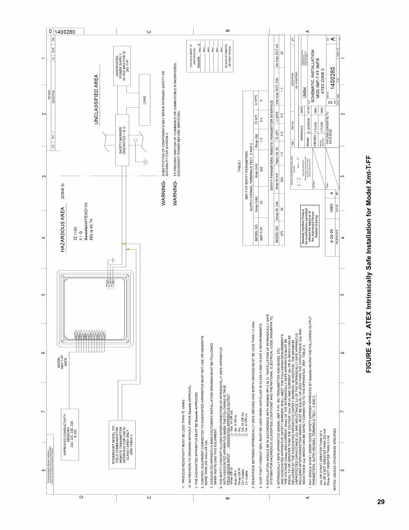
29
FIG
UR
E 4
-12. A
TE
X I
ntr
insic
ally S
afe
In
sta
llati
on
fo
r M
od
el
Xm
t-T-F
F
10/6/
04
10/6/
04
Po;
Isc ,
I t O
R lo
;V
oc, V
tOR
Uo;
Li+
Lcab
le.
Ci+
Cca
ble;
Pm
ax O
R P
iIm
ax O
RIi
Vm
ax O
R U
iF I
ELD
DE
VIC
E IN
PU
T A
SS
OC
IAT E
D A
PP
AR
ATU
S O
UTP
UT
WI T
H A
SS
OC
IATE
D A
PP
AR
ATU
S W
HE
N T
HE
FO
LLO
WIN
G IS
TRU
E:
6 . T
HE
EN
TIT Y
CO
NC
EP
TA
LLO
WS
INTE
RC
ON
NE
CTI
ON
OF
INTR
INS
ICA
LLY
SA
FE A
PP
AR
ATU
S
La, L
t OR
Lo
Ca,
Ct O
R C
o
J. FL
OCK
911
. PR
OC
ES
SR
ES
ISTI
VIT
Y M
US
TB
ELE
SS
THA
N 1
0O
HM
S.
10. N
O R
EV
ISIO
N T
O D
RA
WIN
G W
ITH
OU
T P
RIO
R B
asee
fa A
PP
RO
VA
L.
9. T
HE
AS
SO
CIA
TED
AP
PA
RA
TUS
MU
ST
BE
Bas
eefa
AP
PR
OV
ED
.
Pm
axN
OT
GR
EA
TER
TH
AN
0.9
WIs
cO
R It
NO
T G
RE
ATE
R T
HA
N 2
00 m
AV
oc O
R V
t NO
T G
RE
ATE
R T
HA
N 3
0 V
PA
RA
ME
TER
S: S
UP
PLY
/SIG
NA
L TE
RM
INA
LS T
B2-
1, 2
AN
D 3
.1.
AN
Y S
ING
LE S
HU
NT
ZEN
ER
DIO
DE
SA
FETY
BA
RR
IER
AP
PR
OV
ED
BY
Bas
eefa
HA
VIN
G T
HE
FO
LLO
WIN
G O
UTP
UT
No
mod
ifica
tions
per
mitt
edw
ithou
t the
app
rova
l of
the
Aut
horiz
ed P
erso
nR
elat
ed D
raw
ing
Bas
eefa
Cer
tifie
d P
rodu
ct
EE
x ia
IIC
T4
Bas
eefa
04A
TEX0
215X
II 1
G
1180
(ZO
NE
0)
HAZ
ARD
OU
S A
RE
A
IND
UC
TAN
CE
(La)
WH
ICH
CA
N B
ES
AFE
LY C
ON
NEC
TED
TO
THE
AP
PA
RA
TUS
. (R
EF.
TA
BLE
I).
& 24
522
2, 2
25, 2
26, 2
28,
SE
NS
OR
SA
PP
RO
VE
D C
ON
DU
CTI
VIT
Y
WH
EN
INS
TALL
ING
THIS
EQ
UIP
ME
NT.
7. A
SS
OC
IATE
D A
PP
AR
ATU
S M
AN
UFA
CTU
RE
R'S
INS
TALL
ATI
ON
DR
AW
ING
MU
ST
BE
FO
LLO
WE
D
(SE
E T
AB
LE I)
TAB
LE I
2.IN
TRIN
SIC
ALL
Y S
AFE
AP
PA
RA
TUS
(MO
DE
LXM
T-T-
FF, I
RC
TR
AN
SM
ITTE
R A
ND
MO
DE
L 37
5)
XMTR
XMT-
T-FF
MO
DE
L
XMT-
T-FF
XMT-
T-FF
EN
TITY
PA
RA
ME
TER
S
0.0
SU
PP
LY /
SIG
NA
LTE
RM
INA
LS T
B2-
1, 2
AN
D 3
3 2 1
23456789101112 1
(SE
E N
OTE
S 1
& 9
)S
AFE
TY B
AR
RIE
R
300
30
SYS
TEM
S F
OR
HA
ZAR
DO
US
(CLA
SS
IFIE
D) L
OC
ATI
ON
S"A
ND
TH
E N
ATI
ON
AL
ELE
CTR
ICA
L C
OD
E (A
NS
I/NFP
A 7
0).
3.IN
STA
LLA
TIO
N S
HO
ULD
BE
IN A
CC
OR
DA
NC
E W
ITH
AN
SI/I
SA
RP
12.0
6.01
"IN
STA
LLA
TIO
N O
F IN
TRIN
SIC
ALL
YS
AFE
0.4
MO
DE
L N
O.
01.
3V
max
(Vdc
)Li
(mH
)C
i (nF
)P
max
(W)
Imax
(mA
)
0.0
321.
9
EN
TITY
PA
RA
ME
TER
S: R
EM
OTE
TRA
NS
MIT
TER
INTE
RFA
CE
Isc
max
OU
T:uA
Voc
max
OU
T: V
dcPa
mx
IN: W
Imax
IN:m
AV
max
IN: V
dc37
5M
OD
EL
NO
.1.
020
030
Li (m
H)
Ci (
uF)
FIE
LD C
OM
MU
NIC
ATO
RR
OS
EM
OU
NT
MO
DE
L 37
5
CLA
SS
I A
RE
AO
NLY
INTE
RFA
CE
FO
R U
SE
INR
EM
OTE
TR
AN
SM
ITTE
R
SU
ITA
BIL
ITY
FOR
DIV
ISIO
N 2
.S
UB
STI
TUTI
ON
OF
CO
MP
ON
EN
TS M
AY
IMP
AIR
INTR
INS
IC S
AFE
TY O
R
DIS
CO
NN
EC
T P
OW
ER
BE
FOR
E S
ER
VIC
ING
.TO
PR
EV
EN
T IG
NIT
ION
OF
FLA
MM
AB
LE O
R C
OM
BU
STI
BLE
ATM
OS
PH
ER
ES
,W
AR
NIN
G-
IN
CLU
DIN
G IN
TER
CO
NN
EC
TIN
G W
IRIN
G, M
US
T B
E E
QU
AL
OR
LE
SS
THA
N T
HE
CA
PA
CIT
AN
CE
(Ca)
AN
D U
NP
RO
TEC
TED
CA
PA
CIT
AN
CE
(Ci)
AN
D IN
DU
CTA
NC
E (L
i) O
FTH
E IN
TRIN
SIC
ALL
YS
AFE
AP
PA
RA
TUS
, D
ELI
VE
RE
D B
YTH
E A
SS
OC
IATE
D A
PP
AR
ATU
S (S
AFE
TY B
AR
RIE
R).
IN A
DD
ITIO
N, T
HE
MA
XIM
UM
EQ
UA
L TO
OR
GR
EA
TER
TH
AN
TH
EV
OLT
AG
E(V
oc O
R V
t) AN
D C
UR
RE
NT
(Isc
OR
It) W
HIC
H C
AN
BE
THE
VO
LTA
GE
(Vm
ax) A
ND
CU
RR
EN
T (Im
ax) O
F TH
E IN
TRIN
SIC
ALL
YS
AFE
AP
PA
RA
TUS
MU
ST
BE
AN
D A
SS
OC
IATE
D A
PP
AR
ATU
S (S
AFE
TY B
AR
RIE
R) S
HA
LLM
EE
TTH
E F
OLL
OW
ING
RE
QU
IRE
ME
NTS
:
24V
TYP
30 V
DC
MA
X FO
R IS
PO
WE
R S
UP
PLY
UN
SP
EC
IFIE
D
5. R
ES
ISTA
NC
E B
ETW
EE
N IN
TRIN
SIC
ALL
Y S
AFE
GR
OU
ND
AN
D E
AR
TH G
RO
UN
D M
US
T B
E L
ES
STH
AN
1.0
Ohm
.
4. D
US
T-TI
GH
T C
ON
DU
IT S
EA
L M
US
TB
E U
SE
D W
HE
N IN
STA
LLE
D IN
CLA
SS
IIA
ND
CLA
SS
III E
NV
IRO
NM
EN
TS.
WA
RN
ING
-
UN
CLA
SS
IFIE
D A
RE
A
LOA
D
MO
RE
TH
AN
250
Vrm
sO
R V
dc.
8. C
ON
TRO
L E
QU
IPM
EN
T C
ON
NE
CTE
D T
OA
SS
OC
IATE
D A
PP
AR
ATU
S M
US
T N
OT
US
E O
R G
EN
ER
ATE
THIS
DO
CU
MEN
T IS
CER
TIFI
ED
BY
RE
V
RE
V
RE
V
RE
V
RE
V
RE
V
REVIS
IONS
NOT
PERM
ITTED
W/O
AGEN
CYAP
PROV
AL
ATE
XZO
NE
0M
OD
XM
T-T-
FF X
MTR
B. JO
HNSO
NS
CH
EM
ATIC
, IN
STA
LLA
TIO
N
Unilo
c 9/
15 /0
4NO
MINA
L SUR
FACE
FIN
ISH
125
A90
656-
30-0
5
1400280
11
SHEE
TOF
NONE
J. FL
OCK
A14
0028
0
D
CD
C
B A
12
34
56
78
67
85
43
2
B A
10-9
6
1
D
APPR
OVAL
S.03
0.X
X.X
XX.01
0+ -
ANGL
ES+
1/2
-+-
TOLE
RANC
ES
SOLI
D ED
GE
CHK
REVI
SION
DATE
BYDE
SCRI
PTIO
NEC
OLT
R
NO
TES
: UN
LES
S O
THE
RW
ISE
SP
EC
IFIE
DRE
VEC
O NO
.RE
LEAS
E DA
TE
PART
NO.
ITEM
QTY
BILL
OF
MATE
RIAL
DESC
RIPT
ION
DATE
THIS
DW
GCO
NVER
TED
TO
DRAW
N
CHEC
KED
totho
se w
ho m
ayco
mpete
with
Rose
moun
tAna
lytica
l.Ro
semo
unt A
nalyt
ical, a
nd is
not to
be m
ade a
vaila
bleTh
isdo
cume
ntco
ntains
infor
matio
n pr
oprie
tary t
o
T YPE
SCAL
E
TITL
E
REV
DWG
NO.
SIZE
ENGR
APV
DPR
OJEC
T
MATE
RIAL
FINI
SH
MACH
INED
FILL
ET R
ADII .0
20 M
AXRE
MOVE
BUR
RS &
SHA
RP E
DGES
.020
MAX
DIME
NSIO
NS A
RE IN
INCH
ES
UN
LESS
OTH
ERW
ISE
SP
ECIF
IED
Ros
emou
nt A
naly
tical
,U
nilo
c D
ivis
ion
2400
Bar
ranc
a P
kwy
Irvin
e, C
A92
606
Bas
eefa
A
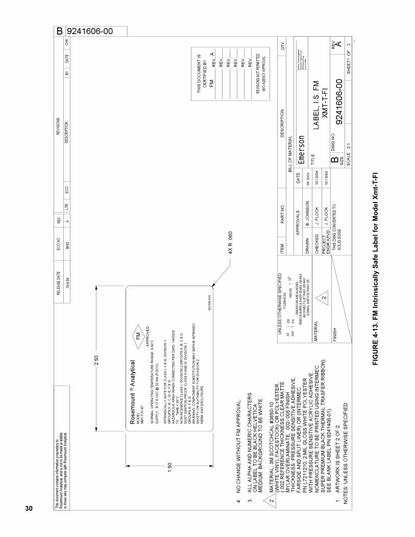
30
FIG
UR
E 4
-13.
FM
In
trin
sic
ally S
afe
Lab
el
for
Mo
del
Xm
t-T-F
I
10
/ 6/0
4 J
. FLO
CK
FAR
S ID
E A
ND
SP
LIT
LIN
ER
) OR
(IN
TER
ME
C
P
N L
7211
210,
2 M
IL G
LOS
S W
HIT
E P
OL Y
ES
TER
WIT
H P
RE
SS U
RE
SE
NS I
TIV
E A
CR
YLI
C A
DH
ES I
VE
.
N
OM
EN
CLA
TUR
E TO
BE
PR
INTE
D U
S IN
G IN
TER
ME
C
S
UP
ER P
RE M
IUM
BLA
CK
THE R
MA
L TR
AS
FER
RIB
BO
N).
SE
E B
LAN
K LA
BE
L P
N 9
2414
06-0
1).
°CT4
T
amb
= 50
R .0
60
XMT-
T-FI
-67
MO
DE
L
4.
NO
CH
ANG
E W
ITH
OU
T FM
AP
PRO
VA
L.
SU
PP
LY
9-17
.5 V
DC
@ 2
2 m
A (F
ISC
O)
XMT-
T-FI
LAB
EL,
I.S
. FM
2
NE
MA
4/4
X E
NC
LOS
UR
ES
AFE
TY O
R S
UIT
AB
ILIT
Y FO
R D
IVIS
ION
2W
AR
NIN
G: C
OM
PO
NEN
T S
UB
STI
TUTI
ON
MA
Y IM
PA
IR IN
TRIN
SIC
GR
OU
PS
E, F
& G
DU
ST
IGN
ITIO
N P
RO
OF
CLA
SS
II A
ND
III,
DIV
ISIO
N 1
,N
ON
-INC
END
IVE
CLA
SS
I, D
IVIS
ION
2 G
RO
UP
S A
, B, C
& D
HAZ
AR
DO
US
AR
EA
WH
ENC
ON
NEC
TED
PER
DW
G. 1
4003
02G
RO
UP
S A
, B, C
, D, E
, F &
GIN
TRIN
SIC
ALL
Y S
AFE
FO
R C
LAS
S I,
II &
III,
DIV
ISIO
N 1
,
4X
AP
PR
OV
ED
FMR
Ros
emou
nt
Ana
lytic
al
9241
606-
00/A
1.50
2.50
1.
AR
TWO
RK
IS S
HE
ET
2 O
F 2.
THIC
KNE
SS.
PR
ES
SUR
E S
ENSI
TIV
E A
DH
ESI
VE
,
M
YLA
R O
VER
LAM
INA
TE, .
002-
.005
FIN
ISH
(.002
RE
FER
ENC
E TH
ICKN
ES
S C
LEAR
MA
TTE
(WH
ITE
VIN
YL
FAC
ES
TOC
K) O
R P
OLY
ES
TER
,2
M
ATE
RIA
L: 3
M S
CO
TCH
CA
L #3
650-
10
ME
DIU
M. B
AC
KGR
OU
ND
TO
BE
WH
ITE
.
O
N L
AB
EL
TO B
E B
LAC
K H
ELV
ETI
CA
3.
ALL
ALP
HA
AN
D N
UM
ER
IC C
HAR
AC
TER
S
Irvine
, CA
9260
624
00 B
arra
nca P
kwy
Rose
moun
t Ana
lytica
l Divi
sion
Emer
son P
roce
ss M
anage
ment,
Emer
son
10
/ 6/0
4
09/ 2
0/04
NOMI
NAL S
URFA
CE FI
NISH
125
10-6
-04
9042
A
9241606-00
B. J
OH
NS
ON
J. F
LOC
K
2:1
A92
4160
6-00
12
SHE
ET
O
F06
-01
TOLE
RANC
ESU
NLE
SS O
THE
RW
ISE
SPE
CIF
IED
ANGL
ES+
1/2
-.03
0.X
X.X
XX.01
0+-+
APP
RO
VAL
S
TITL
E
B
DA
TE
THIS
DW
G CO
NVER
TED
TOSO
LID
EDGE
B
to tho
se w
homa
y com
pete
with
Rose
moun
tAna
lytica
l.Ro
semo
unt A
nalyt
ical, a
nd is
notto
be m
ade a
vaila
bleTh
is do
cume
nt co
ntains
infor
matio
n pro
priet
ary t
o
CHK
DATE
BYDE
SCRI
PTIO
N
REVI
SION
S
ECO
LTR
RELE
ASE
DATE
ECO
NORE
V
NO
TES
: UN
LES
S O
THER
WIS
E S
PE
CIF
IED
EN
GR
APV
DP
RO
JEC
T
CH
EC
KED
DR
AW
N
FIN
ISH
MA
TER
IAL
BIL
L O
F M
ATE
RIA
L
DW
G N
OR
EV
SIZE
SCA
LE
QTY
DE
SCR
IPTI
ON
PAR
T N
OIT
EM
-
MACH
INED
FILL
ET R
ADII .
020 M
AXRE
MOVE
BURR
S &
SHAR
P ED
GES
.020 M
AXDI
MENS
IONS
ARE
IN IN
CHES
THIS
DO
CU
MEN
T IS
CER
TIFI
ED
BY
RE
V
RE
V
RE
V
RE
V
RE
V
RE
V
REVIS
IONS
NOT
PERM
ITTED
W/O
AGEN
CY A
PPRO
VAL
NO
RM
AL
OP
ER
ATI
NG
TE
MP
ER
ATU
RE
RAN
GE
: 0-5
0vC
FMA
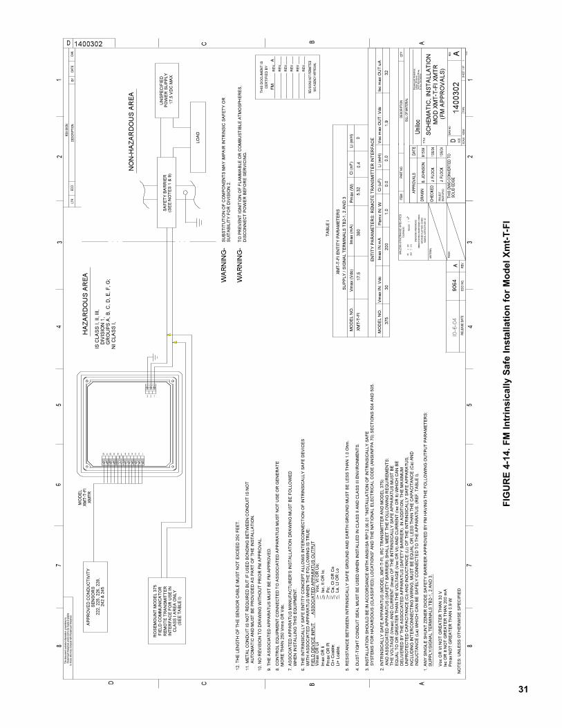
31
FIG
UR
E 4
-14.
FM
In
trin
sic
ally S
afe
In
sta
llati
on
fo
r M
od
el
Xm
t-T-F
I
10/6/
04
10/6/
04
11.M
ETA
L C
ON
DU
ITIS
NO
T R
EQ
UIR
ED
BU
T IF
US
ED
BO
ND
ING
BE
TWE
EN
CO
ND
UIT
IS N
OT
AU
TOM
ATI
C A
ND
MU
STB
E P
RO
VID
ED
AS
PA
RT
OF
THE
INS
TALL
ATI
ON
.
Po;
Isc,
It O
R lo
;V
oc, V
tOR
Uo;
Li+
Lcab
le.
Ci+
Cca
ble;
Pm
ax O
R P
i I
max
OR
Ii V
max
OR
Ui
FIE
LD D
EV
ICE
INP
UT
AS
SO
CIA
TED
AP
PA
RA
TUS
OU
TPU
TW
ITH
AS
SO
CIA
TED
AP
PA
RA
TUS
WH
EN
TH
E F
OLL
OW
ING
IS T
RU
E:
6. T
HE
INTR
INS
ICA
LLY
SA
FE E
NTI
TYC
ON
CE
PT
ALL
OW
S IN
TER
CO
NN
EC
TIO
N O
F IN
TRIN
SIC
ALL
Y S
AFE
DE
VIC
ES
La, L
t OR
Lo
Ca,
Ct O
R C
o
IND
UC
TAN
CE
(La)
WH
ICH
CA
N B
ES
AFE
LY C
ON
NE
CTE
D T
OTH
E A
PP
AR
ATU
S. (
RE
F. T
AB
LE I)
.
242
& 2
4522
2, 2
25, 2
26, 2
28,
SE
NS
OR
SA
PP
RO
VE
D C
ON
DU
CTI
VIT
Y
10. N
O R
EV
ISIO
N T
O D
RA
WIN
GW
ITH
OU
T P
RIO
R F
MA
PP
RO
VA
L.
9.TH
E A
SS
OC
IATE
D A
PP
AR
ATU
S M
US
T B
E F
MA
PP
RO
VE
D.
WH
EN
INS
TALL
ING
TH
ISE
QU
IPM
EN
T.7.
AS
SO
CIA
TED
AP
PA
RA
TUS
MA
NU
FAC
TUR
ER
'S IN
STA
LLA
TIO
N D
RA
WIN
GM
US
T B
E F
OLL
OW
ED
(SE
E T
AB
LE I)
TAB
LE I
Pm
axN
OT
GR
EA
TER
TH
AN
0.9
W Is
c O
R It
NO
TG
RE
ATE
R T
HA
N 2
00m
A V
oc O
R V
tNO
TG
RE
ATE
R T
HA
N 3
0 V
SU
PP
LY/S
IGN
AL
TER
MIN
ALS
TB
2-1,
2 A
ND
3.
1. A
NY
SIN
GLE
SH
UN
T ZE
NE
R D
IOD
E S
AFE
TY B
AR
RIE
R A
PP
RO
VE
D B
Y FM
HA
VIN
G T
HE
FO
LLO
WIN
G O
UTP
UT
PA
RA
ME
TER
S:
2.IN
TRIN
SIC
ALL
Y S
AFE
AP
PA
RA
TUS
(MO
DE
LXM
T-T-
FI, I
RC
TR
AN
SM
ITTE
R A
ND
MO
DE
L 37
5)
XMTR
XMT-
T-FI
MO
DE
L
XMT-
T-FI
XMT-
T-FI
EN
TITY
PA
RA
ME
TER
S
(F
M A
PP
RO
VA
LS)
MO
D X
MT-
T-FI
XM
TR
0.0
SU
PP
LY /
SIG
NA
LTE
RM
INA
LS T
B2-
1, 2
AN
D 3
3 2 1
23456789101112 1
(SE
E N
OTE
S 1
& 9
)S
AFE
TY B
AR
RIE
R
380
17.5
SYS
TEM
S F
OR
HA
ZAR
DO
US
(CLA
SS
IFIE
D) L
OC
ATI
ON
S" A
ND
TH
E N
ATI
ON
AL
ELE
CTR
ICA
L C
OD
E (A
NS
I/NFP
A 7
0) S
EC
TIO
NS
504
AN
D 5
05.
3. IN
STA
LLA
TIO
N S
HO
ULD
BE
IN A
CC
OR
DA
NC
E W
ITH
AN
SI/I
SA
RP
12.0
6.01
"IN
STA
LLA
TIO
N O
FIN
TRIN
SIC
ALL
YS
AFE
0.4
MO
DE
L N
O.
05.
32V
max
(Vdc
)Li
(mH
)C
i (nF
)P
max
(W)
Imax
(mA
)
0.0
321.
9
EN
TITY
PA
RA
ME
TER
S: R
EM
OTE
TRA
NS
MIT
TER
INTE
RFA
CE
Isc
max
OU
T:uA
Voc
max
OU
T: V
dcPa
mx
IN: W
Imax
IN:m
AV
max
IN: V
dc37
5M
OD
EL
NO
.1.
020
030
Li (m
H)
Ci (
uF)
FIE
LD C
OM
MU
NIC
ATO
RR
OS
EM
OU
NT
MO
DE
L 37
5
CLA
SS
I A
RE
AO
NLY
INTE
RFA
CE
FO
R U
SE
INR
EM
OTE
TR
AN
SM
ITTE
R
SU
ITA
BIL
ITY
FOR
DIV
ISIO
N 2
.S
UB
STI
TUTI
ON
OF
CO
MP
ON
EN
TS M
AY
IMP
AIR
INTR
INS
IC S
AFE
TY O
R
DIS
CO
NN
EC
T P
OW
ER
BE
FOR
E S
ER
VIC
ING
.TO
PR
EV
EN
T IG
NIT
ION
OF
FLA
MM
AB
LE O
R C
OM
BU
STI
BLE
ATM
OS
PH
ER
ES
,
NI C
LAS
S I,
G
RO
UP
S A
, B, C
, D, E
, F, G
;
DIV
ISIO
N 1
,IS
CLA
SS
I, II
, III,
HAZ
ARD
OU
S A
RE
A
WA
RN
ING
-
INC
LUD
ING
INTE
RC
ON
NE
CTI
NG
WIR
ING
, MU
ST
BE
EQ
UA
LO
R L
ES
S T
HA
N T
HE
CA
PA
CIT
AN
CE
(Ca)
AN
D U
NP
RO
TEC
TED
CA
PA
CIT
AN
CE
(Ci)
AN
D IN
DU
CTA
NC
E (L
i) O
FTH
E IN
TRIN
SIC
ALL
Y S
AFE
AP
PA
RA
TUS
, D
ELI
VE
RE
D B
YTH
E A
SS
OC
IATE
D A
PP
AR
ATU
S (S
AFE
TYB
AR
RIE
R).
IN A
DD
ITIO
N,T
HE
MA
XIM
UM
EQ
UA
LTO
OR
GR
EA
TER
TH
AN
TH
EV
OLT
AG
E (V
oc O
R V
t) A
ND
CU
RR
EN
T (Is
c O
R It
) WH
ICH
CA
N B
ETH
E V
OLT
AG
E (V
max
) AN
D C
UR
RE
NT
(Imax
) OF
THE
INTR
INS
ICA
LLY
SA
FE A
PP
AR
ATU
S M
US
T B
EA
ND
AS
SO
CIA
TED
AP
PA
RA
TUS
(SA
FETY
BA
RR
IER
) SH
ALL
ME
ET
THE
FO
LLO
WIN
G R
EQ
UIR
EM
EN
TS:
17.5
VD
C M
AX
PO
WE
R S
UP
PLY
UN
SP
EC
IFIE
D
5. R
ES
ISTA
NC
E B
ETW
EE
N IN
TRIN
SIC
ALL
YS
AFE
GR
OU
ND
AN
D E
AR
TH G
RO
UN
D M
US
TB
E L
ES
STH
AN
1.0
Ohm
.
4. D
US
T-TI
GH
T C
ON
DU
IT S
EA
L M
US
TB
E U
SE
D W
HE
N IN
STA
LLE
D IN
CLA
SS
IIA
ND
CLA
SS
III E
NV
IRO
NM
EN
TS.
WA
RN
ING
-
NO
N-H
AZAR
DO
US
AR
EA
LOA
D
MO
RE
TH
AN
250
Vrm
s O
R V
dc.
8. C
ON
TRO
L E
QU
IPM
EN
T C
ON
NE
CTE
D T
O A
SS
OC
IATE
D A
PP
AR
ATU
S M
US
T N
OT
US
EO
R G
EN
ER
ATE
J. F
LOCK
B. JO
HNSO
N
THIS
DO
CU
MEN
T IS
CER
TIFI
ED
BY
RE
V
RE
V
RE
V
RE
V
RE
V
RE
V
REVIS
IONS
NOT
PERM
ITTED
W/O
AGEN
CYAP
PROV
AL
SC
HEM
ATI
C, I
NS
TALL
ATI
ON
Unilo
c 9/
15/04
NOMI
NAL S
URFA
CE F
INIS
H 12
5
A90
6410-6-04
1400302
11
SHEE
TOF
NONE
J. F
LOCK
A14
003 0
2
D
CD
C
B A
12
34
56
78
67
85
43
2
B A
10-9
6
1
D
APPR
OVAL
S.03
0.X
X.X
XX.01
0+ -
ANGL
ES+
1/2
-+-
TOLE
RANC
ES
SOLI
D ED
GE
CHK
REVI
SION
DATE
BYDE
SCRI
PTIO
NEC
OLT
R
NO
TES
: UN
LES
S O
THE
RW
ISE
SP
EC
IFIE
DRE
VEC
O NO
.RE
LEAS
E DA
TE
PART
NO.
ITEM
QTY
BILL
OF
MATE
RIAL
DESC
RIPT
ION
DATE
THIS
DW
GCO
NVER
TED
TO
DRAW
N
CHEC
KED
totho
se w
ho m
ayco
mpete
with
Rose
moun
tAna
lytica
l.Ro
semo
unt A
nalyt
ical, a
nd is
not to
be m
ade a
vaila
bleTh
isdo
cume
ntco
ntains
infor
matio
n pr
oprie
tary t
o
T YPE
SCAL
E
TITL
E
REV
DWG
NO.
SIZE
ENGR
APV
DPR
OJEC
T
MATE
RIAL
FINI
SH
MACH
INED
FILL
ET R
ADII .0
20 M
AXRE
MOVE
BUR
RS &
SHA
RP E
DGES
.020
MAX
DIME
NSIO
NS A
RE IN
INCH
ES
UN
LESS
OTH
ERW
ISE
SP
ECIF
IED
Ros
emou
nt A
naly
tical
,U
nilo
c D
ivis
ion
2400
Bar
ranc
a P
kwy
Irvin
e, C
A92
606
12. T
HE
LE
NG
TH O
FTH
E S
EN
SO
R C
AB
LE M
US
T N
OT
EXC
EE
D 2
50 F
EE
T.
FMA
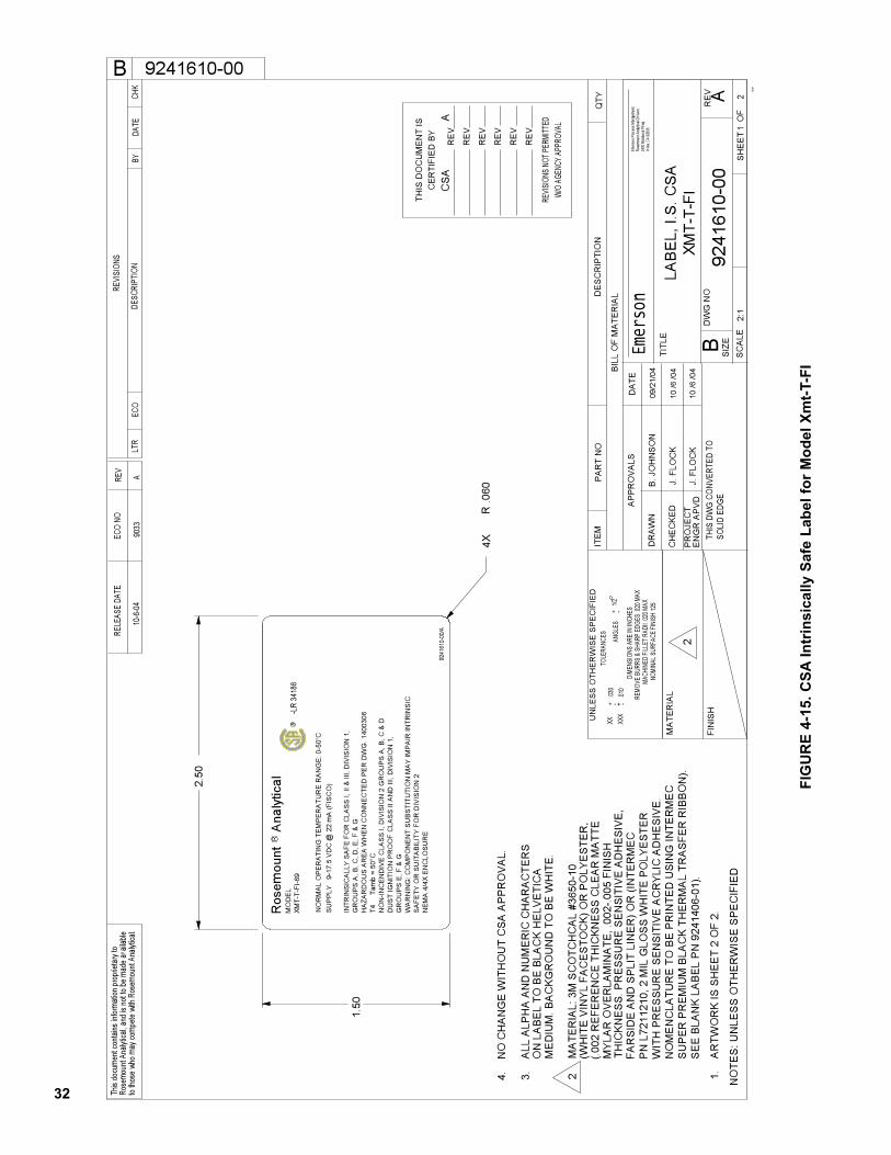
32
FIG
UR
E 4
-15.
CS
AIn
trin
sic
ally S
afe
Lab
el
for
Mo
del
Xm
t-T-F
I
10
/6 /0
4 J
. FLO
CK
FAR
SID
E A
ND
SP
LIT
LIN
ER
) OR
(IN
TER
ME
C
P
N L
7211
210,
2 M
IL G
LOS
S W
HIT
E P
OLY
ES
TER
WIT
H P
RE
SSU
RE
SEN
SITI
VE
AC
RY
LIC
AD
HE
SIV
E.
NO
ME
NC
LATU
RE
TO B
E P
RIN
TED
USI
NG
INTE
RM
EC
SU
PER
PR
EMIU
M B
LAC
K TH
ER
MA
L TR
AS
FER
RIB
BO
N).
SE
E B
LAN
K LA
BE
L P
N 9
2414
06-0
1).
°CT4
T
amb
= 50
R .0
604.
N
O C
HAN
GE
WIT
HO
UT
CS
A A
PP
RO
VA
L.
-LR
3418
6R
LAB
EL,
I.S
. CS
A
XMT-
T-FI
-69
MO
DE
L
SU
PP
LY
9-17
.5 V
DC
@ 2
2 m
A (F
ISC
O)
XMT-
T-FI
2
NE
MA
4/4
X E
NC
LOS
UR
ES
AFE
TY O
R S
UIT
AB
ILIT
Y FO
R D
IVIS
ION
2W
AR
NIN
G: C
OM
PO
NEN
T S
UB
STI
TUTI
ON
MA
Y IM
PA
IR IN
TRIN
SIC
GR
OU
PS
E, F
& G
DU
ST
IGN
ITIO
N P
RO
OF
CLA
SS
II A
ND
III,
DIV
ISIO
N 1
,N
ON
-INC
END
IVE
CLA
SS
I, D
IVIS
ION
2 G
RO
UP
S A
, B, C
& D
HAZ
AR
DO
US
AR
EA
WH
ENC
ON
NEC
TED
PER
DW
G. 1
4003
06G
RO
UP
S A
, B, C
, D, E
, F &
GIN
TRIN
SIC
ALL
Y S
AFE
FO
R C
LAS
S I,
II &
III,
DIV
ISIO
N 1
,
4X
RR
osem
ount
A
naly
tical
9241
610-
00/A
1.50
2.50
1.
AR
TWO
RK
IS S
HE
ET
2 O
F 2.
T
HIC
KNE
SS.
PR
ES
SUR
E S
EN
SITI
VE
AD
HE
SIV
E,
M
YLA
R O
VER
LAM
INA
TE, .
002-
.005
FIN
ISH
(.
002
RE
FER
ENC
E TH
ICKN
ES
S C
LEAR
MA
TTE
(W
HIT
E V
INY
L FA
CE
STO
CK)
OR
PO
LYE
STE
R,
2
MA
TER
IAL:
3M
SC
OTC
HC
AL
#365
0-10
M
ED
IUM
. BA
CKG
RO
UN
D T
O B
E W
HIT
E.
O
N L
AB
EL
TO B
E B
LAC
K H
ELV
ETI
CA
3.
ALL
ALP
HA
AN
D N
UM
ER
IC C
HAR
ACTE
RS
Irvine
, CA
9260
624
00 B
arra
nca P
kwy
Rose
moun
t Ana
lytica
l Divi
sion
Emer
son P
roce
ss M
anage
ment,
Emer
son
10
/6 /0
4
09/
21/0
4NO
MINA
L SUR
FACE
FINI
SH 12
5
10-6
-04
9033
A
9241610-00
B. J
OH
NS
ON
J. F
LOC
K
2:1
A92
4161
0-00
12
SH
EE
T
OF
06-01
TOLE
RANC
ESU
NLE
SS O
THE
RW
ISE
SPE
CIF
IED
ANGL
ES+
1/2
-.03
0.X
X.X
XX.01
0+-+
APP
RO
VAL
S
TITL
E
B
DA
TE
THIS
DW
G CO
NVER
TED
TOSO
LID
EDGE
B
to tho
se w
homa
y com
pete
with
Rose
moun
tAna
lytica
l.Ro
semo
unt A
nalyt
ical, a
nd is
notto
be m
ade a
vaila
bleTh
is do
cume
nt co
ntains
infor
matio
n pro
priet
ary t
o
CHK
DATE
BYDE
SCRI
PTIO
N
REVI
SION
S
ECO
LTR
RELE
ASE
DATE
ECO
NORE
V
NO
TES
: UN
LES
S O
THER
WIS
E S
PE
CIF
IED
EN
GR
APV
DP
RO
JEC
T
CH
EC
KED
DR
AW
N
FIN
ISH
MA
TER
IAL
BIL
L O
F M
ATE
RIA
L
DW
G N
OR
EV
SIZE
SCA
LE
QTY
DE
SCR
IPTI
ON
PAR
T N
OIT
EM
-
MACH
INED
FILL
ET R
ADII .
020 M
AXRE
MOVE
BURR
S &
SHAR
P ED
GES
.020 M
AXDI
MENS
IONS
ARE
IN IN
CHES
THIS
DO
CU
MEN
T IS
CER
TIFI
ED
BY
RE
V
RE
V
RE
V
RE
V
RE
V
RE
V
REVIS
IONS
NOT
PERM
ITTED
W/O
AGEN
CY A
PPRO
VAL
NO
RM
AL
OP
ER
ATI
NG
TE
MP
ER
ATU
RE
RAN
GE
: 0-5
0vC
CS
AA
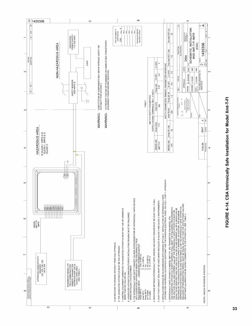
33
FIG
UR
E 4
-14.
CS
AIn
trin
sic
ally S
afe
In
sta
llati
on
fo
r M
od
el
Xm
t-T-F
I
10/6/
04
10/6/
04
J. FL
OCK
J. FL
OCK
HAZ
ARD
OU
S A
RE
A
C
LAS
S II
I
CLA
SS
II, G
RP
S E
-GIS
CLA
SS
I, G
RP
S A
-D
Po;
Isc,
It O
R lo
;V
oc, V
tOR
Uo;
8. T
HE
AS
SO
CIA
T ED
AP
PA
RA
TUS
MU
ST
BE
CS
A A
PP
RO
VE
D.
IND
UC
TAN
CE
(La)
WH
ICH
CA
N B
ES
AFE
LY C
ON
NE
CTE
D T
OTH
E A
PP
AR
ATU
S. (
RE
F.TA
BLE
I).
242
& 2
4522
2, 2
25, 2
26, 2
28,
SE
NS
OR
SA
PP
RO
VE
D C
ON
DU
CTI
VIT
Y
9. N
O R
EV
ISIO
N T
O D
RA
WIN
G W
ITH
OU
T P
RIO
R C
SA A
PP
RO
VA
L.
WH
EN
INS
TALL
ING
TH
ISE
QU
IPM
EN
T.6.
AS
SO
CIA
TED
AP
PA
RA
TUS
MA
NU
FAC
TUR
ER
'S IN
STA
LLA
TIO
N D
RA
WIN
G M
US
T B
E F
OLL
OW
ED
(SE
E T
AB
LE I)
TAB
LE I
1.IN
TRIN
SIC
ALL
Y S
AFE
AP
PA
RA
TUS
(MO
DE
L XM
T-T-
FI, I
RC
TR
AN
SM
ITTE
R A
ND
MO
DE
L 37
5)
XMTR
XMT-
T-FI
MO
DE
L
XMT-
T-FI
XMT-
T-FI
EN
TITY
PA
RA
ME
TER
S
0.0
SU
PP
LY /
SIG
NA
LTE
RM
INA
LS T
B2-
1, 2
AN
D 3
3 2 1
23456789101112 1
(SE
E N
OTE
8)
SA
FETY
BA
RR
IER
Li+
Lcab
le.
Ci+
Cca
ble;
Pm
ax O
R P
iIm
ax O
RIi
Vm
ax O
R U
iFI
ELD
DE
VIC
E IN
PU
T A
SS
OC
IATE
D A
PP
AR
ATU
S O
UTP
UT
WIT
H A
SS
OC
IATE
D A
PP
AR
ATU
S W
HE
N T
HE
FO
LLO
WIN
G IS
TRU
E:
5.T
HE
INTR
INS
ICA
LLY
SA
FE E
NTI
TY C
ON
CE
PT
ALL
OW
S IN
TER
CO
NN
EC
TIO
N O
F IN
TRIN
SIC
ALL
Y S
AFE
DE
VIC
ES
380
17.5
La, L
t OR
Lo
Ca,
Ct O
R C
o
SYS
TEM
S F
OR
HA
ZAR
DO
US
(CLA
SS
IFIE
D) L
OC
ATI
ON
S" A
ND
TH
E C
AN
AD
IAN
ELE
CTR
ICA
L C
OD
E, C
SA
C22
.1, P
AR
T 1,
AP
PE
ND
IX F
.2.
INS
TALL
ATI
ON
SH
OU
LD B
E IN
AC
CO
RD
AN
CE
WIT
H A
NS
I/IS
A R
P12
.06.
01 "I
NS
TALL
ATI
ON
OF
INTR
INS
ICA
LLY
SA
FE
0.4
MO
DE
L N
O.
05.
32V
max
(Vdc
)Li
(mH
)C
i (nF
)P
max
(W)
Imax
(mA
)
0.0
321.
9
EN
TITY
PA
RA
ME
TER
S: R
EM
OTE
TRA
NS
MIT
TER
INTE
RFA
CE
Isc
max
OU
T:uA
Voc
max
OU
T: V
dcP
max
IN: W
Imax
IN:m
AV
max
IN: V
dc37
5M
OD
EL
NO
.1.
020
030
Li (m
H)
Ci (
uF)
FIE
LD C
OM
MU
NIC
ATO
RR
OS
EM
OU
NT
MO
DE
L 37
5
CLA
SS
I A
RE
AO
NLY
INTE
RFA
CE
FO
R U
SE
INR
EM
OTE
TR
AN
SM
ITTE
R
SU
ITA
BIL
ITY
FOR
DIV
ISIO
N 2
.S
UB
STI
TUTI
ON
OF
CO
MP
ON
EN
TS M
AY
IMP
AIR
INTR
INS
IC S
AFE
TY O
R
DIS
CO
NN
EC
T P
OW
ER
BE
FOR
E S
ER
VIC
ING
.TO
PR
EV
EN
T IG
NIT
ION
OF
FLA
MM
AB
LE O
R C
OM
BU
STI
BLE
ATM
OS
PH
ER
ES
,W
AR
NIN
G-
IN
CLU
DIN
G IN
TER
CO
NN
EC
TIN
G W
IRIN
G, M
US
T B
E E
QU
AL
OR
LE
SS
THA
N T
HE
CA
PA
CIT
AN
CE
(Ca)
AN
D U
NP
RO
TEC
TED
CA
PA
CIT
AN
CE
(Ci)
AN
D IN
DU
CTA
NC
E (L
i) O
FTH
E IN
TRIN
SIC
ALL
YS
AFE
AP
PA
RA
TUS
, D
ELI
VE
RE
D B
YTH
E A
SS
OC
IATE
D A
PP
AR
ATU
S (S
AFE
TYB
AR
RIE
R).
IN A
DD
ITIO
N,T
HE
MA
XIM
UM
EQ
UA
L TO
OR
GR
EA
TER
TH
AN
TH
EV
OLT
AG
E (V
oc O
R V
t) A
ND
CU
RR
EN
T (Is
c O
R It
) WH
ICH
CA
N B
ETH
E V
OLT
AG
E (V
max
) AN
D C
UR
RE
NT
(Imax
) OF
THE
INTR
INS
ICA
LLY
SA
FE A
PP
AR
ATU
S M
US
T B
E A
ND
AS
SO
CIA
TED
AP
PA
RA
TUS
(SA
FETY
BA
RR
IER
) SH
ALL
ME
ET
THE
FO
LLO
WIN
G R
EQ
UIR
EM
EN
TS:
17.5
VD
C M
AXP
OW
ER
SU
PP
LYU
NS
PE
CIF
IED
4. R
ES
ISTA
NC
E B
ETW
EE
N IN
TRIN
SIC
ALL
YS
AFE
GR
OU
ND
AN
D E
AR
TH G
RO
UN
D M
US
TB
E L
ES
S T
HA
N 1
.0 O
hm.
3. D
US
T-TI
GH
T C
ON
DU
IT S
EA
L M
US
TB
E U
SE
D W
HE
N IN
STA
LLE
D IN
CLA
SS
IIA
ND
CLA
SS
III E
NV
IRO
NM
EN
TS.
WA
RN
ING
-
NO
N-H
AZAR
DO
US
AR
EA
LOA
D
MO
RE
TH
AN
250
Vrm
sO
R V
dc.
7. C
ON
TRO
L E
QU
IPM
EN
T C
ON
NE
CTE
D T
OA
SS
OC
IATE
D A
PP
AR
ATU
S M
US
T N
OT
US
E O
R G
EN
ER
ATE
THIS
DO
CU
MEN
T IS
CER
TIFI
ED
BY
RE
V
RE
V
RE
V
RE
V
RE
V
RE
V
REVIS
IONS
NOT
PERM
ITTED
W/O
AGEN
CYAP
PROV
AL
(C
SA
)M
OD
XM
T-T-
FI X
MTR
B. JO
HNSO
NS
CH
EM
ATIC
, IN
STA
LLA
TIO
N
Unilo
c 9/
15/04
NOMI
NAL S
URFA
CE F
INIS
H 12
5
A90
47 1
0-6-
04
1400306
11
SHEE
TOF
NONE
A14
0030
6
D
CD
C
B A
12
34
56
78
67
85
43
2
B A
10-9
6
1
D
APPR
OVAL
S.03
0.X
X.X
XX.01
0+ -
ANGL
ES+
1/2
-+-
TOLE
RANC
ES
SOLI
D ED
GE
CHK
REVI
SION
DATE
BYDE
SCRI
PTIO
NEC
OLT
R
NO
TES
: UN
LES
S O
THE
RW
ISE
SP
EC
IFIE
DRE
VEC
O NO
.RE
LEAS
E DA
TE
PART
NO.
ITEM
QTY
BILL
OF
MATE
RIAL
DESC
RIPT
ION
DATE
THIS
DW
GCO
NVER
TED
TO
DRAW
N
CHEC
KED
totho
se w
ho m
ayco
mpete
with
Rose
moun
tAna
lytica
l.Ro
semo
unt A
nalyt
ical, a
nd is
not to
be m
ade a
vaila
bleTh
isdo
cume
ntco
ntains
infor
matio
n pr
oprie
tary t
o
T YPE
SCAL
E
TITL
E
REV
DWG
NO.
SIZE
ENGR
APV
DPR
OJEC
T
MATE
RIAL
FINI
SH
MACH
INED
FILL
ET R
ADII .0
20 M
AXRE
MOVE
BUR
RS &
SHA
RP E
DGES
.020
MAX
DIME
NSIO
NS A
RE IN
INCH
ES
UN
LESS
OTH
ERW
ISE
SP
ECIF
IED
Ros
emou
nt A
naly
tical
,U
nilo
c D
ivis
ion
2400
Bar
ranc
a P
kwy
Irvin
e, C
A92
606
CS
AA
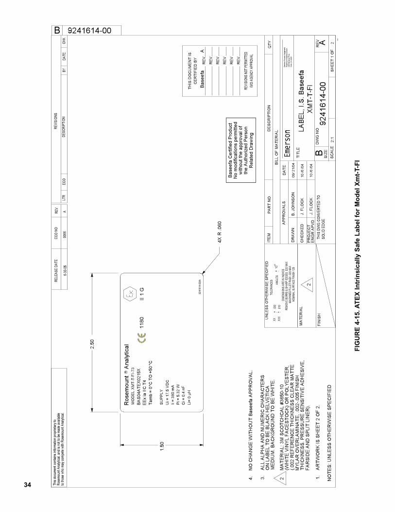
34
FIG
UR
E 4
-15. A
TE
X I
ntr
insic
ally S
afe
Lab
el
for
Mo
del
Xm
t-T-F
I
10 /6
/04
°C°C
TO
+50
Tam
b =
0
R .0
60
No
mod
ifica
tions
perm
itted
with
out t
he a
ppro
val o
fth
e A
utho
rized
Per
son
Rel
ated
Dra
win
g
Bas
eefa
Cer
tifie
d P
rodu
ct
Li=
0 µH
Ci =
0.4
nF
MO
DE
L XM
T-T-
FI-7
3
Pi =
5.3
2 W
Ii =
380
mA
Ui =
17.
5 V
DC
BA
S04
ATE
X021
5XE
Ex ia
IIC
T4
1180
II 1
G
SU
PP
LY
4.
NO
CH
ANG
E W
ITH
OU
T B
asee
fa A
PPR
OV
AL.
LAB
EL,
I.S
. Bas
eefa
XMT-
T-FI
2
4X
RR
osem
ount
A
naly
tical
9241
614-
00/A
1.50
2.50
1.
AR
TWO
RK
IS S
HE
ET
2 O
F 2.
FAR
SID
E A
ND
SP
LIT
LIN
ER
).
TH
ICKN
ES
S. P
RE
SSU
RE
SE
NSI
TIV
E A
DH
ESI
VE
,
MY
LAR
OV
ERLA
MIN
ATE
, .00
2-.0
05 F
INIS
H
(.00
2 R
EFE
REN
CE
THIC
KNE
SS
CLE
AR M
ATT
E
(WH
ITE
VIN
YL
FAC
ES
TOC
K) O
R P
OLY
ES
TER
,2
M
ATE
RIA
L: 3
M S
CO
TCH
CA
L #3
650-
10
M
ED
IUM
. BA
CKG
RO
UN
D T
O B
E W
HIT
E.
O
N L
AB
EL
TO B
E B
LAC
K H
ELV
ETI
CA
3.
ALL
ALP
HA
AN
D N
UM
ER
IC C
HAR
ACTE
RS
Irvine
, CA
9260
624
00 B
arra
nca P
kwy
Rose
moun
t Ana
lytica
l Divi
sion
Emer
son P
roce
ss M
anage
ment,
Emer
son
10 /6
/04
09/ 2
1/04
NOMI
NAL S
URFA
CE FI
NISH
125
6-30
-05
9066
A
9241614-00
B. J
OH
NS
ON
J. F
LOC
K
J. F
LOC
K
2:1
A92
4161
4-00
12
SH
EE
T
OF
06-0 1
TOLE
RANC
ESU
NLE
SS O
THE
RW
ISE
SPE
CIF
IED
ANGL
ES+
1/2
-.03
0.X
X.X
XX.01
0+-+
APP
RO
VAL
S
TITL
E
B
DA
TE
THIS
DW
G CO
NVER
TED
TOSO
LID
EDGE
B
to tho
se w
homa
y com
pete
with
Rose
moun
tAna
lytica
l.Ro
semo
unt A
nalyt
ical, a
nd is
notto
be m
ade a
vaila
bleTh
is do
cume
nt co
ntains
infor
matio
n pro
priet
ary t
o
CHK
DATE
BYDE
SCRI
PTIO
N
REVI
SION
S
ECO
LTR
RELE
ASE
DATE
ECO
NORE
V
NO
TES
: UN
LES
S O
THER
WIS
E S
PE
CIF
IED
EN
GR
APV
DP
RO
JEC
T
CH
EC
KED
DR
AW
N
FIN
ISH
MA
TER
IAL
BIL
L O
F M
ATE
RIA
L
DW
G N
OR
EV
SIZ
ESC
ALE
QTY
DE
SCR
IPTI
ON
PAR
T N
OIT
EM
-
MACH
INED
FILL
ET R
ADII .
020 M
AXRE
MOVE
BURR
S &
SHAR
P ED
GES
.020 M
AXDI
MENS
IONS
ARE
IN IN
CHES
THIS
DO
CU
MEN
T IS
CER
TIFI
ED
BY
RE
V
RE
V
RE
V
RE
V
RE
V
RE
V
REVIS
IONS
NOT
PERM
ITTED
W/O
AGEN
CY A
PPRO
VAL
Bas
eefa
A
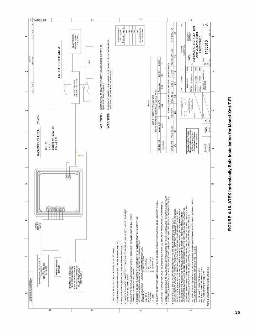
35
FIG
UR
E 4
-16. A
TE
X I
ntr
insic
ally S
afe
In
sta
llati
on
fo
r M
od
el
Xm
t-T-F
I
1 0/6/
04
10/6/
04
Po;
Isc,
It O
R lo
;V
oc, V
tOR
Uo;
Li+
Lcab
le.
Ci+
Cca
ble;
Pm
ax O
R P
iIm
ax O
RIi
Vm
ax O
R U
iFI
ELD
DE
VIC
E IN
PU
T A
SS
OC
IATE
D A
PP
AR
ATU
S O
UTP
UT
WIT
H A
SS
OC
IATE
D A
PP
AR
ATU
S W
HE
N T
HE
FO
LLO
WIN
G IS
TRU
E:
6. T
HE
EN
TITY
CO
NC
EP
TA
LLO
WS
INTE
RC
ON
NE
CTI
ON
OF
INTR
INS
ICA
LLY
SA
FE A
PP
AR
ATU
S
La, L
t OR
Lo
Ca,
Ct O
R C
o
J. F
LOCK
911
. PR
OC
ES
SR
ES
ISTI
VIT
Y M
US
TB
ELE
SS
TH
AN
10
OH
MS
.
SE
NS
OR
AM
PE
RO
ME
TRIC
10. N
O R
EV
ISIO
N T
O D
RA
WIN
G W
ITH
OU
T P
RIO
R B
asee
fa A
PP
RO
VA
L.
9. T
HE
AS
SO
CIA
TED
AP
PA
RA
TUS
MU
ST
BE
Bas
eefa
AP
PR
OV
ED
.
Pm
axN
OT
GR
EA
TER
TH
AN
0.9
WIs
cO
R It
NO
T G
RE
ATE
R T
HA
N 2
00 m
AV
oc O
R V
t NO
T G
RE
ATE
R T
HA
N 3
0 V
PA
RA
ME
TER
S: S
UP
PLY
/SIG
NA
L TE
RM
INA
LS T
B2-
1, 2
AN
D 3
.1.
AN
Y S
ING
LE S
HU
NT
ZEN
ER
DIO
DE
SA
FETY
BA
RR
IER
AP
PR
OV
ED
BY
Bas
eefa
HA
VIN
G T
HE
FO
LLO
WIN
G O
UTP
UT
No
mod
ifica
tions
per
mitt
edw
ithou
t the
app
rova
l of
the
Aut
horiz
ed P
erso
nR
elat
ed D
raw
ing
Bas
eefa
Cer
tifie
d P
rodu
ct
EE
x ia
IIC
T4
Bas
eefa
04A
TEX0
215X
II 1
G
1180
(ZO
NE
0)
HAZ
ARD
OU
S A
RE
A
IND
UC
TAN
CE
(La)
WH
ICH
CA
N B
ES
AFE
LY C
ON
NEC
TED
TO
THE
AP
PA
RA
TUS
. (R
EF.
TA
BLE
I).
242
& 2
4522
2, 2
25, 2
26, 2
28,
SE
NS
OR
SA
PP
RO
VE
D C
ON
DU
CTI
VIT
Y
WH
EN
INS
TALL
ING
THIS
EQ
UIP
ME
NT.
7. A
SS
OC
IATE
D A
PP
AR
ATU
S M
AN
UFA
CTU
RE
R'S
INS
TALL
ATI
ON
DR
AW
ING
MU
ST
BE
FO
LLO
WE
D
(SE
E T
AB
LE I)
TAB
LE I
2. IN
TRIN
SIC
ALL
YS
AFE
AP
PA
RA
TUS
(MO
DE
L XM
T-T-
FI, I
RC
TR
AN
SM
ITTE
R A
ND
MO
DE
L 37
5)
XMTR
XMT-
T-FI
MO
DE
L
XMT-
T-FI
XMT-
T-FI
EN
TITY
PA
RA
ME
TER
S
0.0
SU
PP
LY /
SIG
NA
LTE
RM
INA
LS T
B2-
1, 2
AN
D 3
3 2 1
23456789101112 1
(SE
E N
OTE
S 1
& 9
)S
AFE
TY B
AR
RIE
R
380
17.5
SYS
TEM
S F
OR
HA
ZAR
DO
US
(CLA
SS
IFIE
D) L
OC
ATI
ON
S"A
ND
TH
E N
ATI
ON
AL
ELE
CTR
ICA
L C
OD
E (A
NS
I/NFP
A 7
0).
3.IN
STA
LLA
TIO
N S
HO
ULD
BE
IN A
CC
OR
DA
NC
E W
ITH
AN
SI/I
SA
RP
12.0
6.01
"IN
STA
LLA
TIO
N O
F IN
TRIN
SIC
ALL
YS
AFE
0.4
MO
DE
L N
O.
05.
32V
max
(Vdc
)Li
(mH
)C
i (nF
)P
max
(W)
Imax
(mA
)
0.0
321.
9
EN
TITY
PA
RA
ME
TER
S: R
EM
OTE
TRA
NS
MIT
TER
INTE
RFA
CE
Isc
max
OU
T:uA
Voc
max
OU
T: V
dcPa
mx
IN: W
Imax
IN:m
AV
max
IN: V
dc37
5M
OD
EL
NO
.1.
020
030
Li (m
H)
Ci (
uF)
FIE
LD C
OM
MU
NIC
ATO
RR
OS
EM
OU
NT
MO
DE
L 37
5
CLA
SS
I A
RE
AO
NLY
INTE
RFA
CE
FO
R U
SE
INR
EM
OTE
TR
AN
SM
ITTE
R
SU
ITA
BIL
ITY
FOR
DIV
ISIO
N 2
.S
UB
STI
TUTI
ON
OF
CO
MP
ON
EN
TS M
AY
IMP
AIR
INTR
INS
IC S
AFE
TY O
R
DIS
CO
NN
EC
T P
OW
ER
BE
FOR
E S
ER
VIC
ING
.TO
PR
EV
EN
T IG
NIT
ION
OF
FLA
MM
AB
LE O
R C
OM
BU
STI
BLE
ATM
OS
PH
ER
ES
,W
AR
NIN
G-
IN
CLU
DIN
G IN
TER
CO
NN
EC
TIN
G W
IRIN
G, M
US
T B
E E
QU
AL
OR
LE
SS
THA
N T
HE
CA
PA
CIT
AN
CE
(Ca)
AN
D U
NP
RO
TEC
TED
CA
PA
CIT
AN
CE
(Ci)
AN
D IN
DU
CTA
NC
E (L
i) O
FTH
E IN
TRIN
SIC
ALL
YS
AFE
AP
PA
RA
TUS
, D
ELI
VE
RE
D B
YTH
E A
SS
OC
IATE
D A
PP
AR
ATU
S (S
AFE
TY B
AR
RIE
R).
IN A
DD
ITIO
N, T
HE
MA
XIM
UM
EQ
UA
L TO
OR
GR
EA
TER
TH
AN
TH
EVO
LTA
GE
(Voc
OR
Vt)
AND
CU
RR
EN
T (Is
c O
R It
) WH
ICH
CA
N B
ETH
E V
OLT
AG
E (V
max
) AN
D C
UR
RE
NT
(Imax
) OF
THE
INTR
INS
ICA
LLY
SA
FE A
PP
AR
ATU
S M
US
T B
E A
ND
AS
SO
CIA
TED
AP
PA
RA
TUS
(SA
FETY
BA
RR
IER
) SH
ALL
ME
ET
THE
FO
LLO
WIN
G R
EQ
UIR
EM
EN
TS:
17.5
VD
C M
AX
PO
WE
R S
UP
PLY
UN
SP
EC
IFIE
D
5. R
ES
ISTA
NC
E B
ETW
EE
N IN
TRIN
SIC
ALL
Y S
AFE
GR
OU
ND
AN
D E
AR
TH G
RO
UN
D M
US
T B
E L
ES
STH
AN
1.0
Ohm
.
4. D
US
T-TI
GH
T C
ON
DU
IT S
EA
L M
US
TB
E U
SE
D W
HE
N IN
STA
LLE
D IN
CLA
SS
IIA
ND
CLA
SS
III E
NV
IRO
NM
EN
TS.
WA
RN
ING
-
UN
CLA
SS
IFIE
D A
RE
A
LOA
D
MO
RE
TH
AN
250
Vrm
sO
R V
dc.
8. C
ON
TRO
L E
QU
IPM
EN
T C
ON
NE
CTE
D T
OA
SS
OC
IATE
D A
PP
AR
ATU
S M
US
T N
OT
US
E O
R G
EN
ER
ATE
THIS
DO
CU
MEN
T IS
CER
TIFI
ED
BY
RE
V
RE
V
RE
V
RE
V
RE
V
RE
V
REVIS
IONS
NOT
PERM
ITTED
W/O
AGEN
CYAP
PROV
AL
A
TEX
ZON
E 0
MO
D X
MT-
T-FI
XM
TR
B. JO
HNSO
NS
CH
EM
ATIC
, IN
STA
LLA
TIO
N
Unilo
c 9/
15/04
NOMI
NAL S
URFA
CE F
INIS
H 12
5
A90
656-
30-0
5
1400310
11
SHEE
TOF
NONE
J. F
LOCK
A14
0031
0
D
CD
C
B A
12
34
56
78
67
85
43
2
B A
10-9
6
1
D
APPR
OVAL
S.03
0.X
X.X
XX.01
0+ -
ANGL
ES+
1/2
-+-
TOLE
RANC
ES
SOLI
D ED
GE
CHK
REVI
SION
DATE
BYDE
SCRI
PTIO
NEC
OLT
R
NO
TES
: UN
LES
S O
THE
RW
ISE
SP
EC
IFIE
DRE
VEC
O NO
.RE
LEAS
E DA
TE
PART
NO.
ITEM
QTY
BILL
OF
MATE
RIAL
DESC
RIPT
ION
DATE
THIS
DW
GCO
NVER
TED
TO
DRAW
N
CHEC
KED
totho
se w
ho m
ayco
mpete
with
Rose
moun
tAna
lytica
l.Ro
semo
unt A
nalyt
ical, a
nd is
not to
be m
ade a
vaila
bleTh
isdo
cume
ntco
ntains
infor
matio
n pr
oprie
tary t
o
TYPE
SCAL
E
TITL
E
REV
DWG
NO.
SIZE
ENGR
APV
DPR
OJEC
T
MATE
RIAL
FINI
SH
MACH
INED
FILL
ET R
ADII .0
20 M
AXRE
MOVE
BUR
RS &
SHA
RP E
DGES
.020
MAX
DIME
NSIO
NS A
RE IN
INCH
ES
UN
LESS
OTH
ERW
ISE
SP
ECIF
IED
Ros
emou
nt A
naly
tical
,U
nilo
c D
ivis
ion
2400
Bar
ranc
a P
kwy
Irvin
e, C
A92
606
Bas
eefa
A
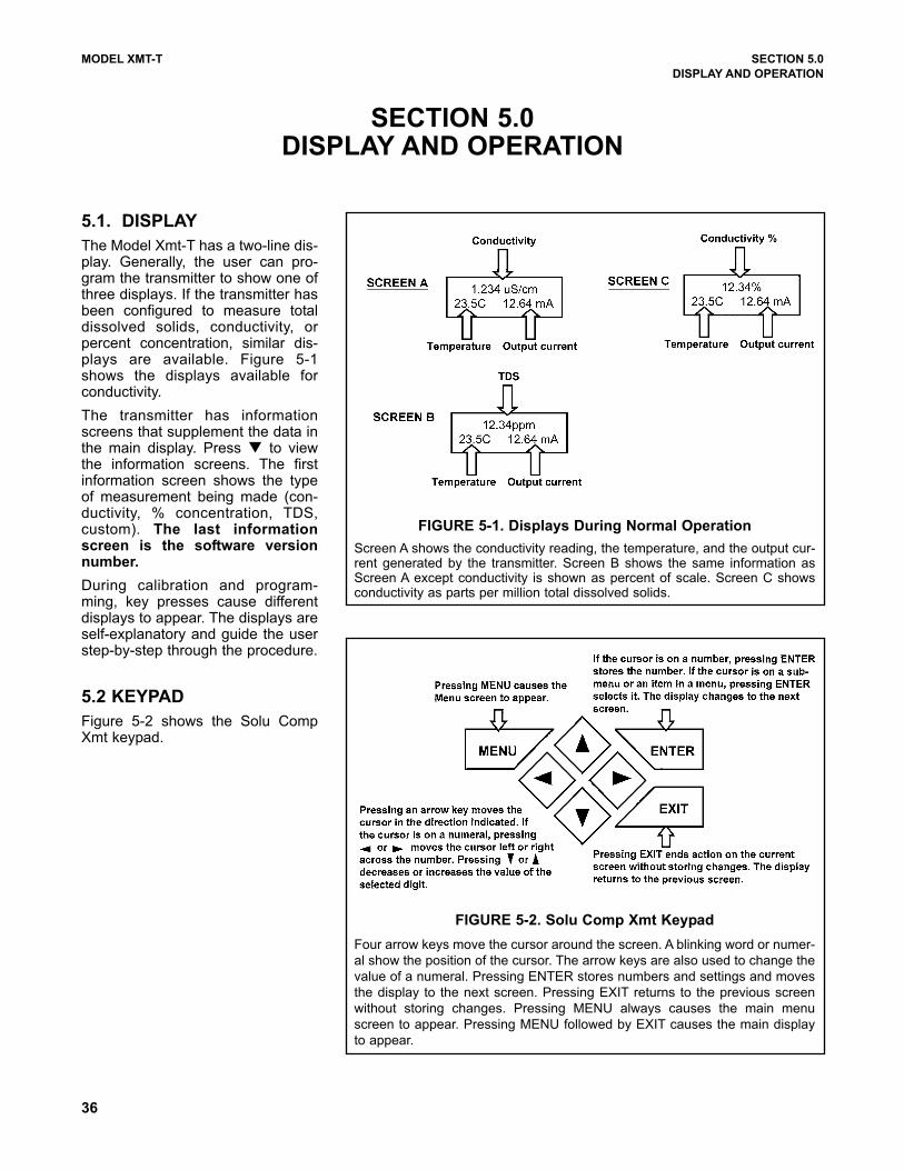
36
MODEL XMT-T SECTION 5.0
DISPLAY AND OPERATION
SECTION 5.0DISPLAY AND OPERATION
5.1. DISPLAY
The Model Xmt-T has a two-line dis-play. Generally, the user can pro-gram the transmitter to show one ofthree displays. If the transmitter hasbeen configured to measure totaldissolved solids, conductivity, orpercent concentration, similar dis-plays are available. Figure 5-1shows the displays available forconductivity.
The transmitter has informationscreens that supplement the data inthe main display. Press to viewthe information screens. The firstinformation screen shows the typeof measurement being made (con-ductivity, % concentration, TDS,custom). The last informationscreen is the software versionnumber.
During calibration and program-ming, key presses cause differentdisplays to appear. The displays areself-explanatory and guide the userstep-by-step through the procedure.
5.2 KEYPAD
Figure 5-2 shows the Solu CompXmt keypad.
FIGURE 5-1. Displays During Normal Operation
Screen A shows the conductivity reading, the temperature, and the output cur-rent generated by the transmitter. Screen B shows the same information asScreen A except conductivity is shown as percent of scale. Screen C showsconductivity as parts per million total dissolved solids.
FIGURE 5-2. Solu Comp Xmt Keypad
Four arrow keys move the cursor around the screen. A blinking word or numer-
al show the position of the cursor. The arrow keys are also used to change the
value of a numeral. Pressing ENTER stores numbers and settings and moves
the display to the next screen. Pressing EXIT returns to the previous screen
without storing changes. Pressing MENU always causes the main menu
screen to appear. Pressing MENU followed by EXIT causes the main display
to appear.
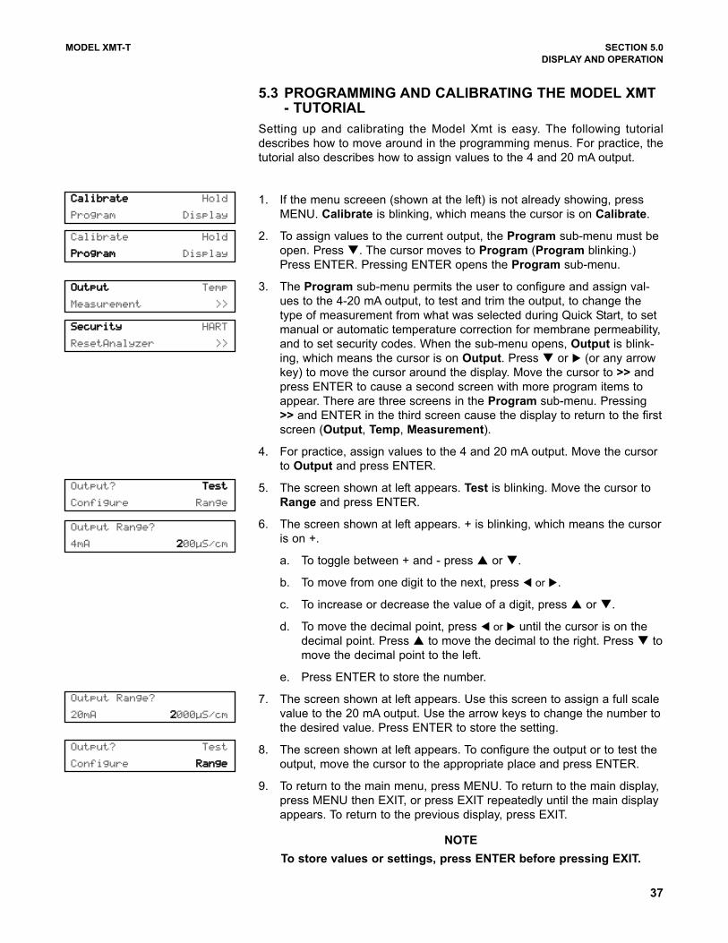
MODEL XMT-T SECTION 5.0
DISPLAY AND OPERATION
5.3 PROGRAMMING AND CALIBRATING THE MODEL XMT- TUTORIAL
Setting up and calibrating the Model Xmt is easy. The following tutorial
describes how to move around in the programming menus. For practice, the
tutorial also describes how to assign values to the 4 and 20 mA output.
1. If the menu screeen (shown at the left) is not already showing, press
MENU. Calibrate is blinking, which means the cursor is on Calibrate.
2. To assign values to the current output, the Program sub-menu must be
open. Press . The cursor moves to Program (Program blinking.)
Press ENTER. Pressing ENTER opens the Program sub-menu.
3. The Program sub-menu permits the user to configure and assign val-
ues to the 4-20 mA output, to test and trim the output, to change the
type of measurement from what was selected during Quick Start, to set
manual or automatic temperature correction for membrane permeability,
and to set security codes. When the sub-menu opens, Output is blink-
ing, which means the cursor is on Output. Press or (or any arrow
key) to move the cursor around the display. Move the cursor to >> and
press ENTER to cause a second screen with more program items to
appear. There are three screens in the Program sub-menu. Pressing
>> and ENTER in the third screen cause the display to return to the first
screen (Output, Temp, Measurement).
4. For practice, assign values to the 4 and 20 mA output. Move the cursor
to Output and press ENTER.
5. The screen shown at left appears. Test is blinking. Move the cursor to
Range and press ENTER.
6. The screen shown at left appears. + is blinking, which means the cursor
is on +.
a. To toggle between + and - press or .
b. To move from one digit to the next, press or .
c. To increase or decrease the value of a digit, press or .
d. To move the decimal point, press or until the cursor is on the
decimal point. Press to move the decimal to the right. Press to
move the decimal point to the left.
e. Press ENTER to store the number.
7. The screen shown at left appears. Use this screen to assign a full scale
value to the 20 mA output. Use the arrow keys to change the number to
the desired value. Press ENTER to store the setting.
8. The screen shown at left appears. To configure the output or to test the
output, move the cursor to the appropriate place and press ENTER.
9. To return to the main menu, press MENU. To return to the main display,
press MENU then EXIT, or press EXIT repeatedly until the main display
appears. To return to the previous display, press EXIT.
NOTE
To store values or settings, press ENTER before pressing EXIT.
CCaalliibbrraattee Hold
Program Display
Calibrate Hold
PPrrooggrraamm Display
OOuuttppuutt Temp
Measurement >>
SSeeccuurriittyy HART
ResetAnalyzer >>
Output Range?
20mA 22000µS/cm
Output Range?
4mA 2200µS/cm
Output? TTeesstt
Configure Range
Output? Test
Configure RRaannggee
37
38
MODEL XMT-T SECTION 5.0
DISPLAY AND OPERATION
5.4 MENU TREES — TOROIDAL CONDUCTIVITY
The Model Xmt-T-HT transmitter has four menus: CALIBRATE, PROGRAM, HOLD, and DISPLAY. Under the
Calibrate and Program menus are several sub-menus. For example, under CALIBRATE, the sub-menus are
Conductivity, % Concentration, and Temperature. Under each sub-menu are prompts. Under PROGRAM,
the sub-menus for Xmt-T-HT are Output, Temp, Measurement, Security, HART, and Reset Analyzer. The
HOLD menu (HART only) enables or disables the 4-20 mA outputs. The DISPLAY menu allows the user to con-
figure the main display information fields and to adjust the LCD display contrast. Figure 5-3 shows the complete
menu tree for Model Xmt-T-HT. Figure 5-4 shows the complete menu tree for Model Xmt-T-FF.
5.5 DIAGNOSTIC MESSAGES
Whenever a warning or fault limit has been exceeded, the transmitter displays diagnostic messages to aid in trou-
bleshooting. “Fault” or “Warn” appears in the main display to alert the user of an adverse condition. The display
alternates between the regular display and the Fault or Warning message. If more than one warning or fault mes-
sage has been generated, the messages appear alternately.
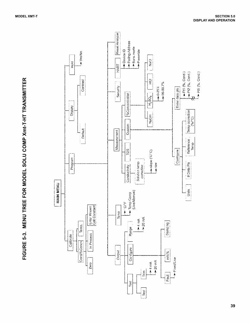
39
MODEL XMT-T SECTION 5.0
DISPLAY AND OPERATION
FIG
UR
E 5
-3.
ME
NU
TR
EE
FO
R M
OD
EL
SO
LU
CO
MP
Xm
t-T-H
T T
RA
NS
MIT
TE
R
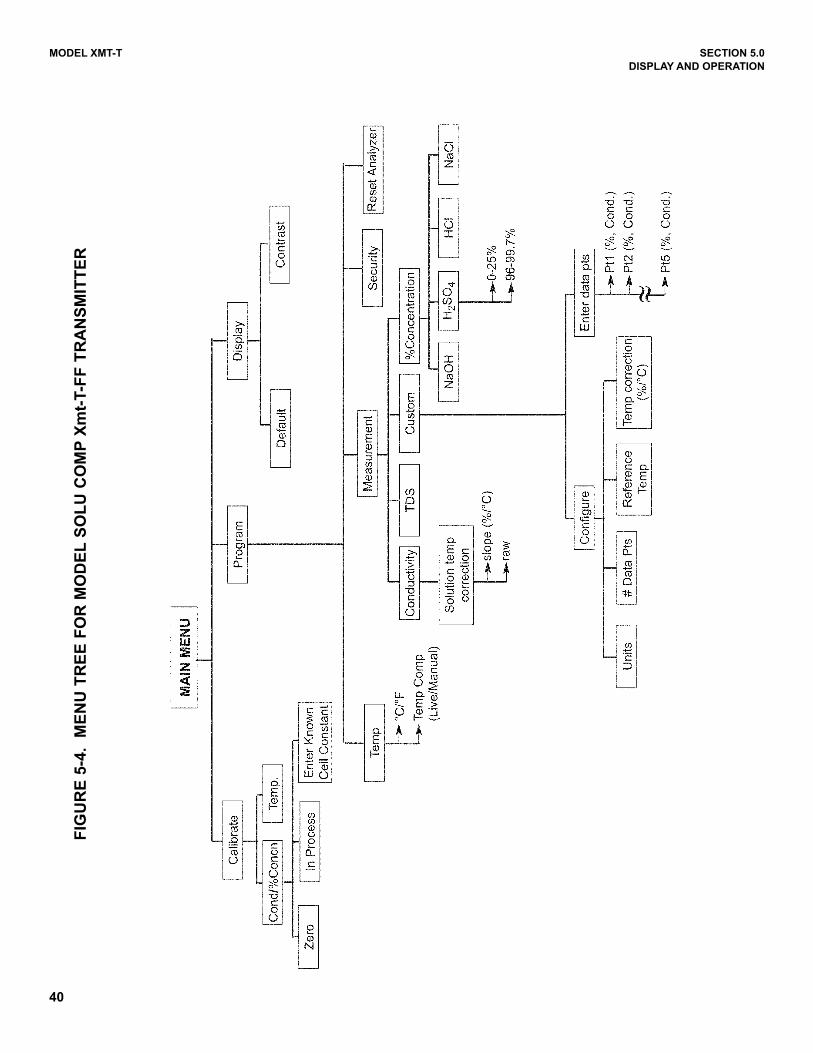
40
MODEL XMT-T SECTION 5.0
DISPLAY AND OPERATION
FIG
UR
E 5
-4.
ME
NU
TR
EE
FO
R M
OD
EL
SO
LU
CO
MP
Xm
t-T-F
F T
RA
NS
MIT
TE
R
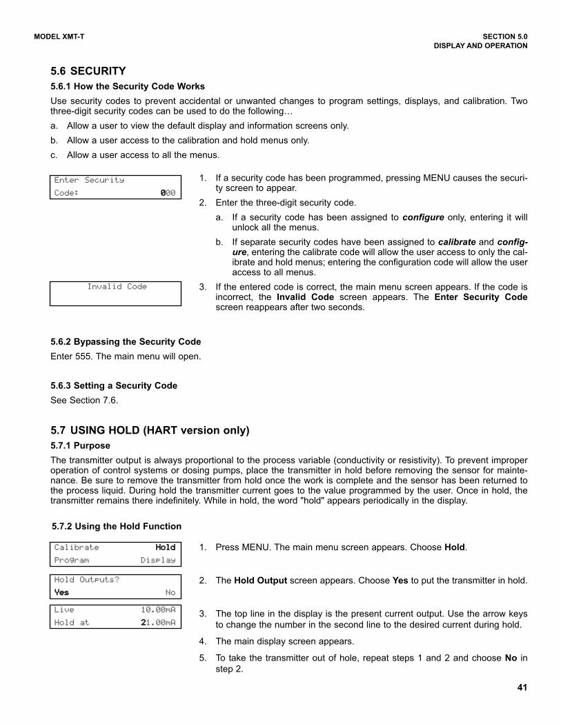
MODEL XMT-T SECTION 5.0
DISPLAY AND OPERATION
1. If a security code has been programmed, pressing MENU causes the securi-ty screen to appear.
2. Enter the three-digit security code.
a. If a security code has been assigned to configure only, entering it willunlock all the menus.
b. If separate security codes have been assigned to calibrate and config-ure, entering the calibrate code will allow the user access to only the cal-ibrate and hold menus; entering the configuration code will allow the useraccess to all menus.
3. If the entered code is correct, the main menu screen appears. If the code isincorrect, the Invalid Code screen appears. The Enter Security Codescreen reappears after two seconds.
Enter Security
Code: 0000
Invalid Code
Calibrate HHoolldd
Program Display
Hold Outputs?
YYeess No
5.6 SECURITY
5.6.1 How the Security Code Works
Use security codes to prevent accidental or unwanted changes to program settings, displays, and calibration. Twothree-digit security codes can be used to do the following…
a. Allow a user to view the default display and information screens only.
b. Allow a user access to the calibration and hold menus only.
c. Allow a user access to all the menus.
5.6.2 Bypassing the Security Code
Enter 555. The main menu will open.
5.6.3 Setting a Security Code
See Section 7.6.
5.7 USING HOLD (HART version only)
5.7.1 Purpose
The transmitter output is always proportional to the process variable (conductivity or resistivity). To prevent improperoperation of control systems or dosing pumps, place the transmitter in hold before removing the sensor for mainte-nance. Be sure to remove the transmitter from hold once the work is complete and the sensor has been returned tothe process liquid. During hold the transmitter current goes to the value programmed by the user. Once in hold, thetransmitter remains there indefinitely. While in hold, the word "hold" appears periodically in the display.
5.7.2 Using the Hold Function
1. Press MENU. The main menu screen appears. Choose Hold.
2. The Hold Output screen appears. Choose Yes to put the transmitter in hold.
3. The top line in the display is the present current output. Use the arrow keys
to change the number in the second line to the desired current during hold.
4. The main display screen appears.
5. To take the transmitter out of hole, repeat steps 1 and 2 and choose No in
step 2.
Live 10.00mA
Hold at 221.00mA
41
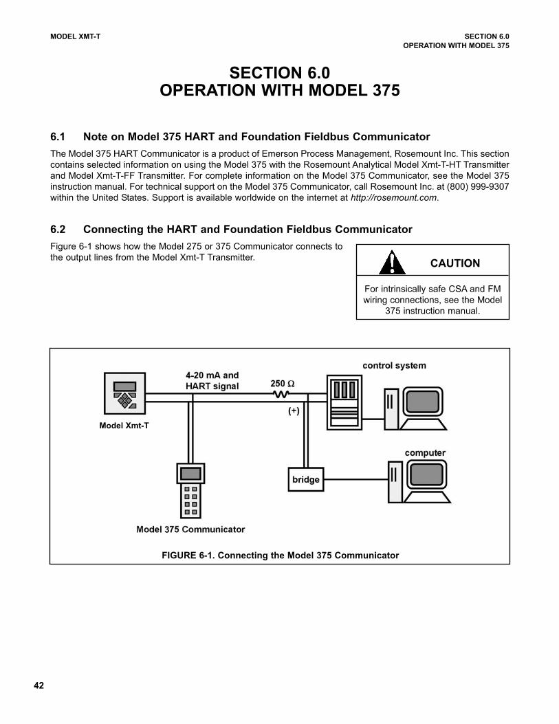
42
MODEL XMT-T SECTION 6.0
OPERATION WITH MODEL 375
SECTION 6.0OPERATION WITH MODEL 375
6.1 Note on Model 375 HART and Foundation Fieldbus Communicator
The Model 375 HART Communicator is a product of Emerson Process Management, Rosemount Inc. This section
contains selected information on using the Model 375 with the Rosemount Analytical Model Xmt-T-HT Transmitter
and Model Xmt-T-FF Transmitter. For complete information on the Model 375 Communicator, see the Model 375
instruction manual. For technical support on the Model 375 Communicator, call Rosemount Inc. at (800) 999-9307
within the United States. Support is available worldwide on the internet at http://rosemount.com.
6.2 Connecting the HART and Foundation Fieldbus Communicator
Figure 6-1 shows how the Model 275 or 375 Communicator connects to
the output lines from the Model Xmt-T Transmitter.CAUTION
For intrinsically safe CSA and FM
wiring connections, see the Model
375 instruction manual.
FIGURE 6-1. Connecting the Model 375 Communicator
Model Xmt-T
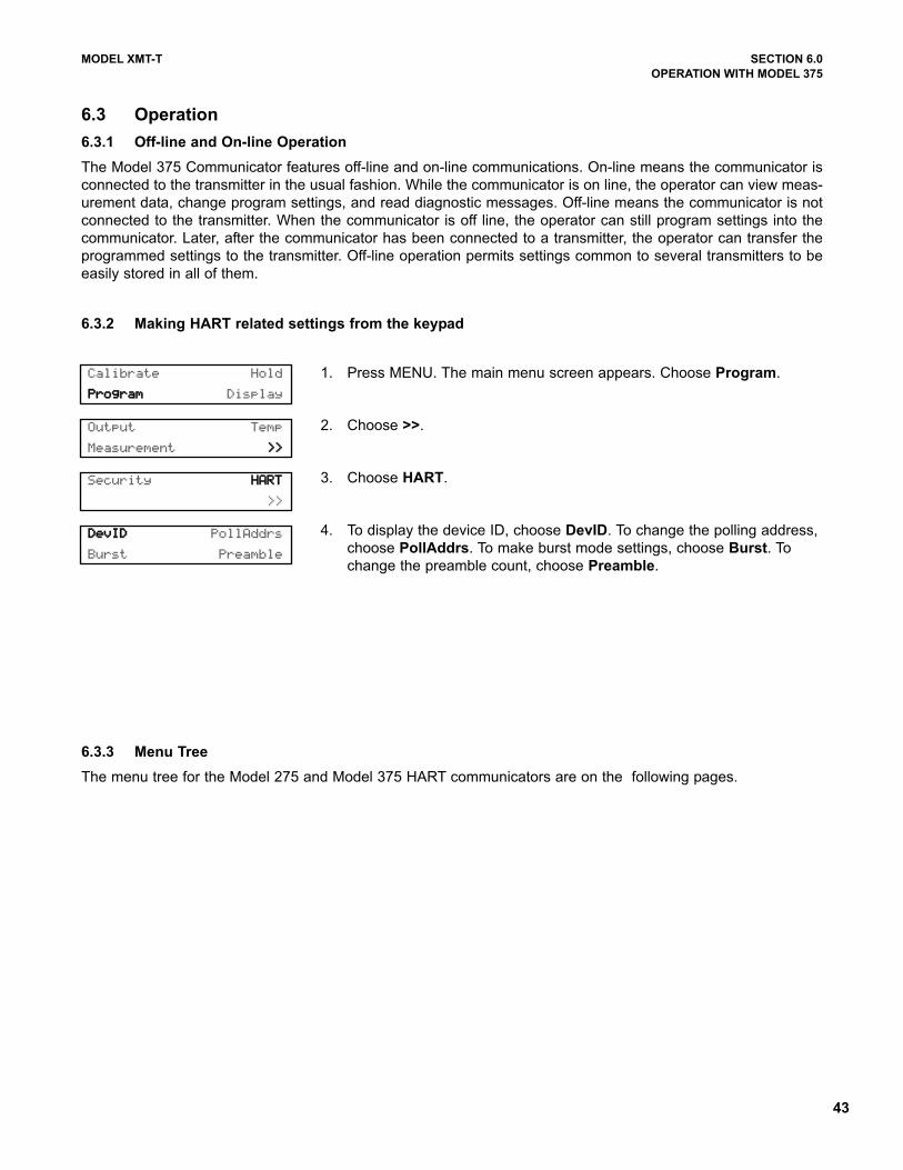
43
MODEL XMT-T SECTION 6.0
OPERATION WITH MODEL 375
6.3 Operation
6.3.1 Off-line and On-line Operation
The Model 375 Communicator features off-line and on-line communications. On-line means the communicator is
connected to the transmitter in the usual fashion. While the communicator is on line, the operator can view meas-
urement data, change program settings, and read diagnostic messages. Off-line means the communicator is not
connected to the transmitter. When the communicator is off line, the operator can still program settings into the
communicator. Later, after the communicator has been connected to a transmitter, the operator can transfer the
programmed settings to the transmitter. Off-line operation permits settings common to several transmitters to be
easily stored in all of them.
6.3.2 Making HART related settings from the keypad
6.3.3 Menu Tree
The menu tree for the Model 275 and Model 375 HART communicators are on the following pages.
1. Press MENU. The main menu screen appears. Choose Program.
2. Choose >>.
3. Choose HART.
4. To display the device ID, choose DevID. To change the polling address,
choose PollAddrs. To make burst mode settings, choose Burst. To
change the preamble count, choose Preamble.
Calibrate Hold
PPrrooggrraamm Display
Output Temp
Measurement >>>>
Security HHAARRTT
>>
DDeevvIIDD PollAddrs
Burst Preamble

44
MODEL XMT-T SECTION 6.0
OPERATION WITH MODEL 375
Device setup
Process variables
Cond *
Raw
Conductance
Temp
Temp res
View status
Diag/Service
Test device
Loop test
View status
Master reset
Fault history
Hold mode
Calibration
Calibrate sensor
Zero in air
Zero in solution **
Adjust temperature
Calibrate input *...
Cell constant
Temp slope ***
D/A trim
Diagnostic vars
Cond *
Temp
Cell constant
Zero offset
Soln offset **
Temp slope ***
Input cal factor
Basic setup
Tag
PV range values
PV LRV
PV URV
PV
PV % rnge
Device information
Distributor
Model
Dev id
Tag
Date
Physicl signl code
Write protect
Snsr text
Descriptor
Message
Revision #'s
Universal rev
Fld dev rev
Software rev
Hardware rev
FIGURE 6-2. Xmt-T-HT HART/Model 375 Menu Tree (1 of 3)
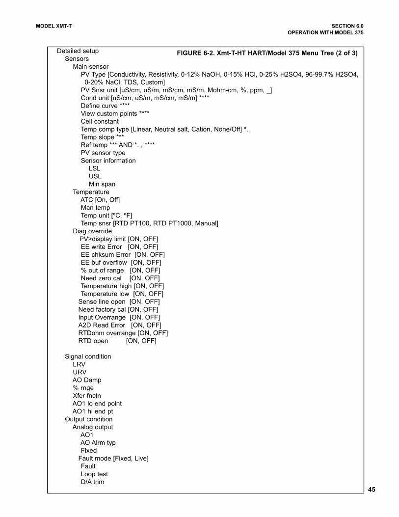
45
MODEL XMT-T SECTION 6.0
OPERATION WITH MODEL 375
Detailed setup
Sensors
Main sensor
PV Type [Conductivity, Resistivity, 0-12% NaOH, 0-15% HCl, 0-25% H2SO4, 96-99.7% H2SO4,
0-20% NaCl, TDS, Custom]
PV Snsr unit [uS/cm, uS/m, mS/cm, mS/m, Mohm-cm, %, ppm, _]
Cond unit [uS/cm, uS/m, mS/cm, mS/m] ****
Define curve ****
View custom points ****
Cell constant
Temp comp type [Linear, Neutral salt, Cation, None/Off] *..
Temp slope ***
Ref temp *** AND *. , ****
PV sensor type
Sensor information
LSL
USL
Min span
Temperature
ATC [On, Off]
Man temp
Temp unit [ºC, ºF]
Temp snsr [RTD PT100, RTD PT1000, Manual]
Diag override
PV>display limit [ON, OFF]
EE write Error [ON, OFF]
EE chksum Error [ON, OFF]
EE buf overflow [ON, OFF]
% out of range [ON, OFF]
Need zero cal [ON, OFF]
Temperature high [ON, OFF]
Temperature low [ON, OFF]
Sense line open [ON, OFF]
Need factory cal [ON, OFF]
Input Overrange [ON, OFF]
A2D Read Error [ON, OFF]
RTDohm overrange [ON, OFF]
RTD open [ON, OFF]
Signal condition
LRV
URV
AO Damp
% rnge
Xfer fnctn
AO1 lo end point
AO1 hi end pt
Output condition
Analog output
AO1
AO Alrm typ
Fixed
Fault mode [Fixed, Live]
Fault
Loop test
D/A trim
FIGURE 6-2. Xmt-T-HT HART/Model 375 Menu Tree (2 of 3)
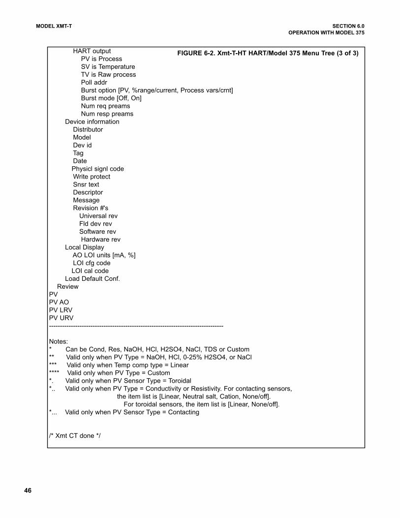
46
MODEL XMT-T SECTION 6.0
OPERATION WITH MODEL 375
HART output
PV is Process
SV is Temperature
TV is Raw process
Poll addr
Burst option [PV, %range/current, Process vars/crnt]
Burst mode [Off, On]
Num req preams
Num resp preams
Device information
Distributor
Model
Dev id
Tag
Date
Physicl signl code
Write protect
Snsr text
Descriptor
Message
Revision #'s
Universal rev
Fld dev rev
Software rev
Hardware rev
Local Display
AO LOI units [mA, %]
LOI cfg code
LOI cal code
Load Default Conf.
Review
PV
PV AO
PV LRV
PV URV
--------------------------------------------------------------------------------
Notes:
* Can be Cond, Res, NaOH, HCl, H2SO4, NaCl, TDS or Custom
** Valid only when PV Type = NaOH, HCl, 0-25% H2SO4, or NaCl
*** Valid only when Temp comp type = Linear
**** Valid only when PV Type = Custom
*. Valid only when PV Sensor Type = Toroidal
*.. Valid only when PV Type = Conductivity or Resistivity. For contacting sensors,
the item list is [Linear, Neutral salt, Cation, None/off].
For toroidal sensors, the item list is [Linear, None/off].
*... Valid only when PV Sensor Type = Contacting
/* Xmt CT done */
FIGURE 6-2. Xmt-T-HT HART/Model 375 Menu Tree (3 of 3)
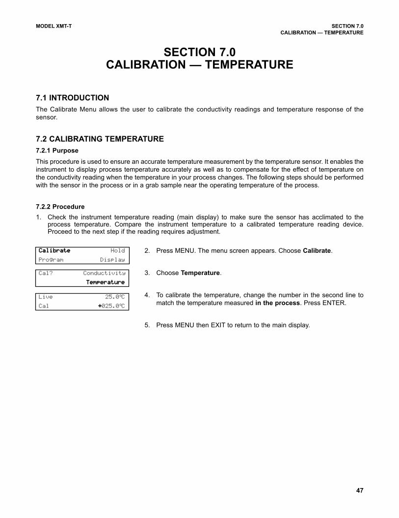
47
MODEL XMT-T SECTION 7.0
CALIBRATION — TEMPERATURE
SECTION 7.0CALIBRATION — TEMPERATURE
7.1 INTRODUCTION
The Calibrate Menu allows the user to calibrate the conductivity readings and temperature response of the
sensor.
7.2 CALIBRATING TEMPERATURE
7.2.1 Purpose
This procedure is used to ensure an accurate temperature measurement by the temperature sensor. It enables the
instrument to display process temperature accurately as well as to compensate for the effect of temperature on
the conductivity reading when the temperature in your process changes. The following steps should be performed
with the sensor in the process or in a grab sample near the operating temperature of the process.
7.2.2 Procedure
1. Check the instrument temperature reading (main display) to make sure the sensor has acclimated to theprocess temperature. Compare the instrument temperature to a calibrated temperature reading device.Proceed to the next step if the reading requires adjustment.
2. Press MENU. The menu screen appears. Choose Calibrate.
3. Choose Temperature.
4. To calibrate the temperature, change the number in the second line to
match the temperature measured in the process. Press ENTER.
5. Press MENU then EXIT to return to the main display.
Cal? Conductivity
TTeemmppeerraattuurree
CCaalliibbrraattee Hold
Program Display
Live 25.0ºC
Cal ++025.0ºC
48
MODEL XMT-T SECTION 8.0
CALIBRATION — CONDUCTIVITY
SECTION 8.0CALIBRATION — CONDUCTIVITY
The following procedures are described in this section:
• Entering the cell constant (Section 8.2)
• Zeroing the transmitter (Section 8.3)
• Calibrating the sensor in a Conductivity Standard (Section 8.4)
• Entering the temperature slope (Section 8.5)
8.1 INTRODUCTION
Calibration is the process of adjusting or standardizing the transmitter to a lab test (such as free acid titration) or
a calibrated laboratory instrument, or standardizing to some known reference (such as a commercial chemical
standard). Calibration ensures that the transmitter reads an accurate, and therefore, repeatable reading of con-
ductivity and temperature. This section contains procedures for the first time use and for routine calibration of the
Model Xmt-T transmitter.
Since conductivity measurements are affected by temperature, the Model Xmt-T reads the temperature at the
probe and compensates for the changing temperature by referencing all conductivity measurements to 25°C
(77°F).
To ensure the transmitter's accuracy, it is important to perform all the calibration procedures provided in this sec-
tion if you are:
• installing this unit for the first time
• changing or replacing a probe
• troubleshooting
After the initial calibration, the accuracy of the conductivity reading should be checked periodically against some
known standard of conductivity and temperature.
Entering the cell constant, zeroing the instrument, and calibrating the sensor should be done when first commis-
sioning the Xmt and when changing the conductivity probe. These operations should be conducted with the con-
ductivity probe wired to the transmitter with full length of extension cable (if any) for best results.
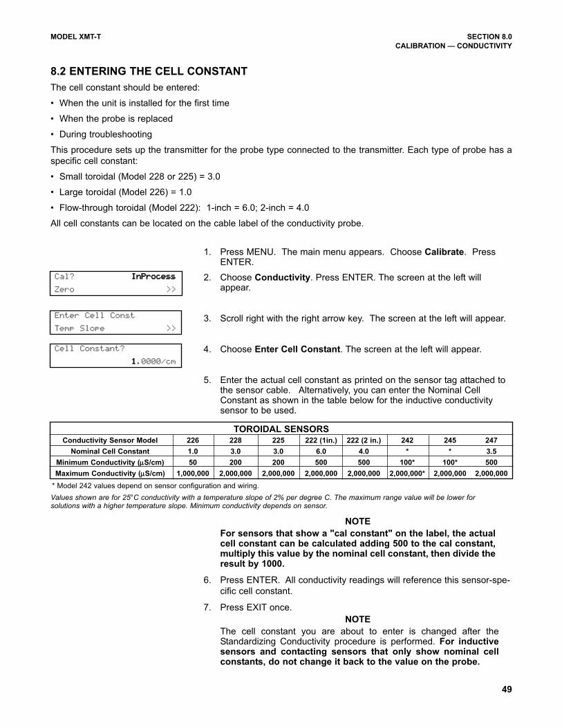
49
MODEL XMT-T SECTION 8.0
CALIBRATION — CONDUCTIVITY
8.2 ENTERING THE CELL CONSTANT
The cell constant should be entered:
• When the unit is installed for the first time
• When the probe is replaced
• During troubleshooting
This procedure sets up the transmitter for the probe type connected to the transmitter. Each type of probe has a
specific cell constant:
• Small toroidal (Model 228 or 225) = 3.0
• Large toroidal (Model 226) = 1.0
• Flow-through toroidal (Model 222): 1-inch = 6.0; 2-inch = 4.0
All cell constants can be located on the cable label of the conductivity probe.
1. Press MENU. The main menu appears. Choose Calibrate. PressENTER.
2. Choose Conductivity. Press ENTER. The screen at the left willappear.
3. Scroll right with the right arrow key. The screen at the left will appear.
4. Choose Enter Cell Constant. The screen at the left will appear.
5. Enter the actual cell constant as printed on the sensor tag attached tothe sensor cable. Alternatively, you can enter the Nominal CellConstant as shown in the table below for the inductive conductivitysensor to be used.
NOTE
For sensors that show a "cal constant" on the label, the actualcell constant can be calculated adding 500 to the cal constant,multiply this value by the nominal cell constant, then divide theresult by 1000.
6. Press ENTER. All conductivity readings will reference this sensor-spe-
cific cell constant.
7. Press EXIT once.
NOTE
The cell constant you are about to enter is changed after theStandardizing Conductivity procedure is performed. For inductivesensors and contacting sensors that only show nominal cellconstants, do not change it back to the value on the probe.
Enter Cell Const
Temp Slope >>
Cal? IInnPPrroocceessss
Zero >>
Cell Constant?
11.0000/cm
Values shown are for 25°C conductivity with a temperature slope of 2% per degree C. The maximum range value will be lower forsolutions with a higher temperature slope. Minimum conductivity depends on sensor.
TOROIDAL SENSORSConductivity Sensor Model 226 228 225 222 (1in.) 222 (2 in.) 242 245 247
Nominal Cell Constant 1.0 3.0 3.0 6.0 4.0 * * 3.5
Minimum Conductivity (µµS/cm) 50 200 200 500 500 100* 100* 500
Maximum Conductivity (µµS/cm) 1,000,000 2,000,000 2,000,000 2,000,000 2,000,000 2,000,000* 2,000,000 2,000,000
* Model 242 values depend on sensor configuration and wiring.
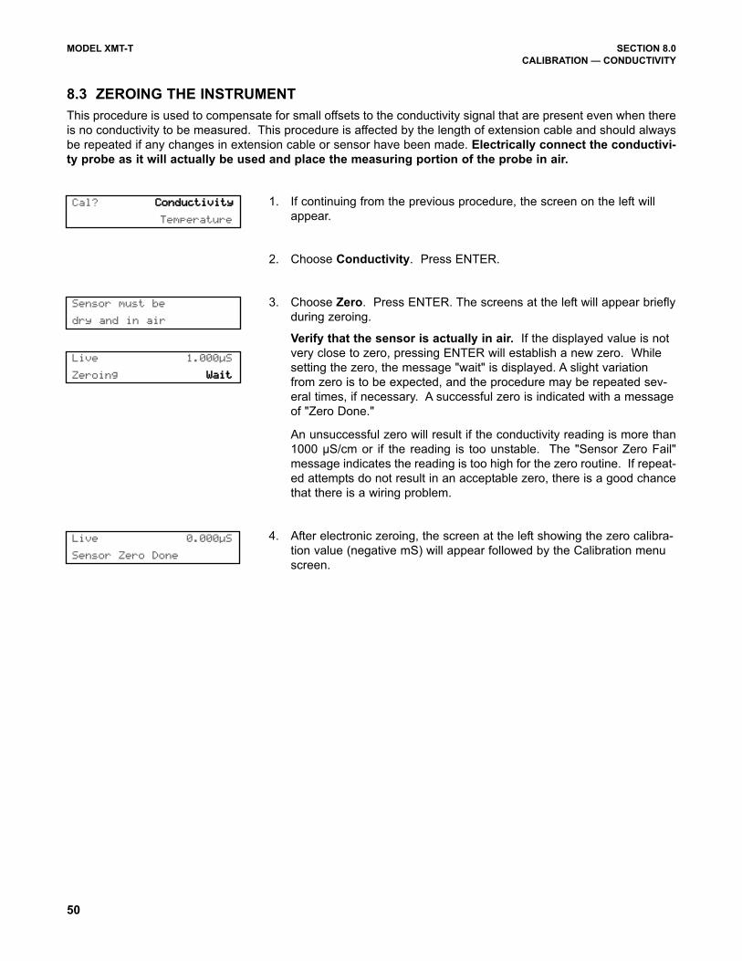
50
MODEL XMT-T SECTION 8.0
CALIBRATION — CONDUCTIVITY
8.3 ZEROING THE INSTRUMENT
This procedure is used to compensate for small offsets to the conductivity signal that are present even when there
is no conductivity to be measured. This procedure is affected by the length of extension cable and should always
be repeated if any changes in extension cable or sensor have been made. Electrically connect the conductivi-
ty probe as it will actually be used and place the measuring portion of the probe in air.
1. If continuing from the previous procedure, the screen on the left will
appear.
2. Choose Conductivity. Press ENTER.
3. Choose Zero. Press ENTER. The screens at the left will appear briefly
during zeroing.
Verify that the sensor is actually in air. If the displayed value is not
very close to zero, pressing ENTER will establish a new zero. While
setting the zero, the message "wait" is displayed. A slight variation
from zero is to be expected, and the procedure may be repeated sev-
eral times, if necessary. A successful zero is indicated with a message
of "Zero Done."
An unsuccessful zero will result if the conductivity reading is more than
1000 µS/cm or if the reading is too unstable. The "Sensor Zero Fail"
message indicates the reading is too high for the zero routine. If repeat-
ed attempts do not result in an acceptable zero, there is a good chance
that there is a wiring problem.
4. After electronic zeroing, the screen at the left showing the zero calibra-
tion value (negative mS) will appear followed by the Calibration menu
screen.
Live 0.000µS
Sensor Zero Done
Live 1.000µS
Zeroing WWaaiitt
Cal? CCoonndduuccttiivviittyy
Temperature
Sensor must be
dry and in air
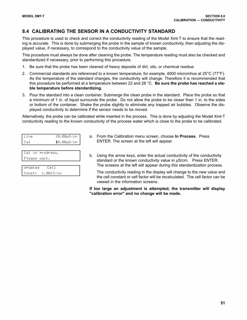
51
MODEL XMT-T SECTION 8.0
CALIBRATION — CONDUCTIVITY
8.4 CALIBRATING THE SENSOR IN A CONDUCTIVITY STANDARD
This procedure is used to check and correct the conductivity reading of the Model Xmt-T to ensure that the read-
ing is accurate. This is done by submerging the probe in the sample of known conductivity, then adjusting the dis-
played value, if necessary, to correspond to the conductivity value of the sample.
This procedure must always be done after cleaning the probe. The temperature reading must also be checked and
standardized if necessary, prior to performing this procedure.
1. Be sure that the probe has been cleaned of heavy deposits of dirt, oils, or chemical residue.
2. Commercial standards are referenced to a known temperature, for example, 4000 micromhos at 25°C (77°F).
As the temperature of the standard changes, the conductivity will change. Therefore it is recommended that
this procedure be performed at a temperature between 22 and 28 °C. Be sure the probe has reached a sta-
ble temperature before standardizing.
3. Pour the standard into a clean container. Submerge the clean probe in the standard. Place the probe so that
a minimum of 1 in. of liquid surrounds the probe. Do not allow the probe to be closer than 1 in. to the sides
or bottom of the container. Shake the probe slightly to eliminate any trapped air bubbles. Observe the dis-
played conductivity to determine if the sensor needs to be moved.
Alternatively, the probe can be calibrated while inserted in the process. This is done by adjusting the Model Xmt-T
conductivity reading to the known conductivity of the process water which is close to the probe to be calibrated.
a. From the Calibration menu screen, choose In Process. Press
ENTER. The screen at the left will appear.
b. Using the arrow keys, enter the actual conductivity of the conductivity
standard or the known conductivity value in µS/cm. Press ENTER.
The screens at the left will appear during this standardization process.
The conductivity reading in the display will change to the new value and
the cell constant or cell factor will be recalculated. The cell factor can be
viewed in the information screens.
If too large an adjustment is attempted, the transmitter will display
"calibration error" and no change will be made.
Updated Cell
Const: 1.0013/cm
Cal in progress.
Please wait.
Live 10.00µS/cm
Cal 110.00µS/cm
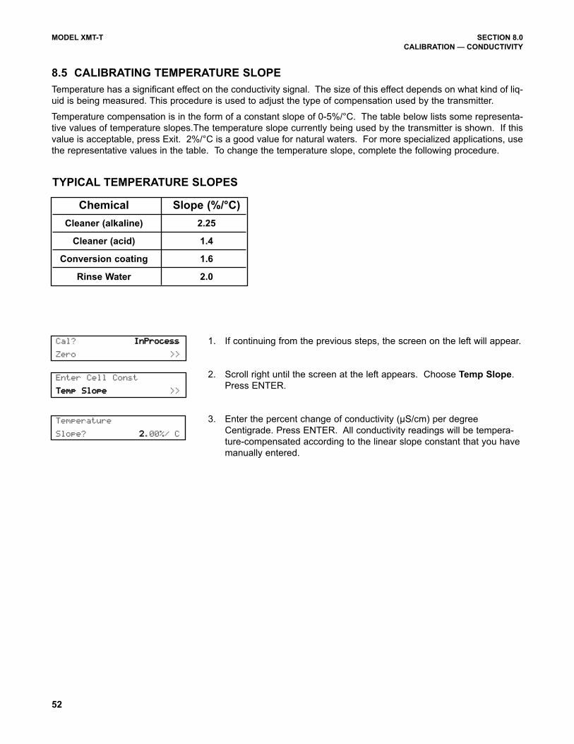
52
MODEL XMT-T SECTION 8.0
CALIBRATION — CONDUCTIVITY
8.5 CALIBRATING TEMPERATURE SLOPE
Temperature has a significant effect on the conductivity signal. The size of this effect depends on what kind of liq-
uid is being measured. This procedure is used to adjust the type of compensation used by the transmitter.
Temperature compensation is in the form of a constant slope of 0-5%/°C. The table below lists some representa-
tive values of temperature slopes.The temperature slope currently being used by the transmitter is shown. If this
value is acceptable, press Exit. 2%/°C is a good value for natural waters. For more specialized applications, use
the representative values in the table. To change the temperature slope, complete the following procedure.
1. If continuing from the previous steps, the screen on the left will appear.
2. Scroll right until the screen at the left appears. Choose Temp Slope.
Press ENTER.
3. Enter the percent change of conductivity (µS/cm) per degree
Centigrade. Press ENTER. All conductivity readings will be tempera-
ture-compensated according to the linear slope constant that you have
manually entered.
Temperature
Slope? 22.00%/ C
Enter Cell Const
TTeemmpp SSllooppee >>
Cal? IInnPPrroocceessss
Zero >>
TYPICAL TEMPERATURE SLOPES
Chemical Slope (%/°C)
Cleaner (alkaline) 2.25
Cleaner (acid) 1.4
Conversion coating 1.6
Rinse Water 2.0
53
MODEL XMT-T SECTION 9.0
PROGRAMMING THE TRANSMITTER
SECTION 9.0PROGRAMMING THE TRANSMITTER
9.1 GENERAL
This section describes how to program the transmitter using the keypad.
1. Configure and assign values to the 4-20 mA output [-HT version only] (Section 9.3)
2. Test and trim the current output [-HT version only] (Section 9.3)
3. Select the measurement to be made [conductivity, TDS, % concentration, or custom] (Section 9.4)
4. Choose temperature units and automatic or manual temperature mode (Section 9.5)
5. Set a security code (Section 9.6)
6. Resetting factory default settings (Section 9.8)
7. Selecting a default display screen and adjusting screen constrast (Section 9.9)
9.2 CHANGING START-UP SETTINGS
When the Solu Comp Xmt is powered up for the first time, startup screens appear. The screens prompt the
user to enter the measurement being made and enter the cell constant of the sensor being used, to select a
specific conductivity concentration curve (if % Concentration was selected), and to select temperature units. If
incorrect settings were entered at startup, enter the correct settings now. To change the measurement, refer
to Section 9.4.
54
MODEL XMT-T SECTION 9.0
PROGRAMMING THE TRANSMITTER
9.3 CONFIGURING AND RANGING THE OUTPUT (-HT version only)
9.3.1 Purpose
1. Configuring an output means
a. displaying the output reading in units of mA or percent of full scale.
b. changing the time constant for output dampening.
c. assigning the value the output current will take if the transmitter detects a fault in itself or the sensor.
2. Ranging the output means assigning values to the 4 mA and 20 mA outputs.
3. Testing an output means entering a test value from the keypad to check the operation of recorders or trans-
mitters.
4. Trimming an output means calibrating the 4 and 20 mA current outputs against a referee milliammeter.
9.3.2 Definitions
1. CURRENT OUTPUT. The transmitter provides a continuous 4-20 mA output current directly proportional to
the pH of the sample.
2. FAULT. The transmitter continuously monitors itself and the sensor for faults. If the transmitter detects a
fault, the 4-20 mA output can be programmed to go to a fixed value or it can be programmed to continue
to display the live current reading. In any event Fault appears intermittently in the second line of the dis-
play.
3. DAMPEN. Output dampening smooths out noisy readings. But it also increases the response time of the out-
put. To estimate the time (in minutes) required for the output to reach 95% of the final reading following a step
change, divide the setting by 20. Thus, a setting of 140 means that, following a step change, the output takes
about seven minutes to reach 95% of final reading. The output dampen setting does not affect the response
time of the process display. The maximum setting is 255.
4. TEST. The transmitter can be programmed to generate a test current.
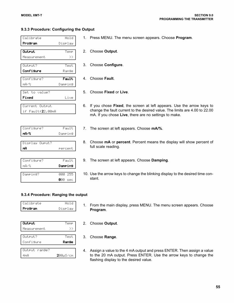
55
MODEL XMT-T SECTION 9.0
PROGRAMMING THE TRANSMITTER
9.3.3 Procedure: Configuring the Output
1. Press MENU. The menu screen appears. Choose Program.
2. Choose Output.
3. Choose Configure.
4. Choose Fault.
5. Choose Fixed or Live.
6. If you chose Fixed, the screen at left appears. Use the arrow keys to
change the fault current to the desired value. The limits are 4.00 to 22.00
mA. If you chose Live, there are no settings to make.
7. The screen at left appears. Choose mA/%.
8. Choose mA or percent. Percent means the display will show percent of
full scale reading.
9. The screen at left appears. Choose Damping.
10. Use the arrow keys to change the blinking display to the desired time con-
stant.
1. From the main display, press MENU. The menu screen appears. Choose
Program.
2. Choose Output.
3. Choose Range.
4. Assign a value to the 4 mA output and press ENTER. Then assign a value
to the 20 mA output. Press ENTER. Use the arrow keys to change the
flashing display to the desired value.
Calibrate Hold
PPrrooggrraamm Display
Display Ouput?
mmAA percent
OOuuttppuutt Temp
Measurement >>
Configure? FFaauulltt
mA/% Damping
Configure? Fault
mmAA//%% Damping
Configure? Fault
mA/% DDaammppiinngg
Set to value?
FFiixxeedd Live
Current Output
if Fault:222.00mA
Damping? 000 255
0000 sec
Output range?
4mA 2200µS/cm
Output? Test
CCoonnffiigguurree Range
OOuuttppuutt Temp
Measurement >>
Output? Test
Configure RRaannggee
9.3.4 Procedure: Ranging the output
Calibrate Hold
PPrrooggrraamm Display
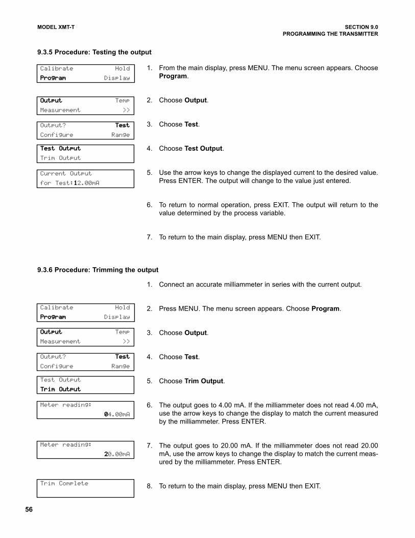
56
MODEL XMT-T SECTION 9.0
PROGRAMMING THE TRANSMITTER
Current Output
for Test:112.00mA
OOuuttppuutt Temp
Measurement >>
TTeesstt OOuuttppuutt
Trim Output
Output? TTeesstt
Configure Range
9.3.5 Procedure: Testing the output
Calibrate Hold
PPrrooggrraamm Display
1. From the main display, press MENU. The menu screen appears. Choose
Program.
2. Choose Output.
3. Choose Test.
4. Choose Test Output.
5. Use the arrow keys to change the displayed current to the desired value.
Press ENTER. The output will change to the value just entered.
6. To return to normal operation, press EXIT. The output will return to the
value determined by the process variable.
7. To return to the main display, press MENU then EXIT.
Meter reading:
004.00mA
Meter reading:
220.00mA
Trim Complete
OOuuttppuutt Temp
Measurement >>
Test Output
TTrriimm OOuuttppuutt
Output? TTeesstt
Configure Range
9.3.6 Procedure: Trimming the output
Calibrate Hold
PPrrooggrraamm Display
1. Connect an accurate milliammeter in series with the current output.
2. Press MENU. The menu screen appears. Choose Program.
3. Choose Output.
4. Choose Test.
5. Choose Trim Output.
6. The output goes to 4.00 mA. If the milliammeter does not read 4.00 mA,
use the arrow keys to change the display to match the current measured
by the milliammeter. Press ENTER.
7. The output goes to 20.00 mA. If the milliammeter does not read 20.00
mA, use the arrow keys to change the display to match the current meas-
ured by the milliammeter. Press ENTER.
8. To return to the main display, press MENU then EXIT.
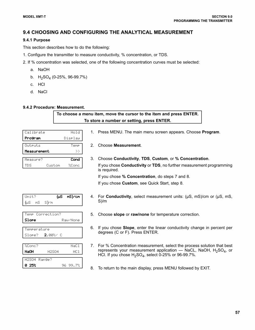
57
MODEL XMT-T SECTION 9.0
PROGRAMMING THE TRANSMITTER
9.4 CHOOSING AND CONFIGURING THE ANALYTICAL MEASUREMENT
9.4.1 Purpose
This section describes how to do the following:
1. Configure the transmitter to measure conductivity, % concentration, or TDS.
2. If % concentration was selected, one of the following concentration curves must be selected:
a. NaOH
b. H2SO4 (0-25%, 96-99.7%)
c. HCl
d. NaCl
9.4.2 Procedure: Measurement.
To choose a menu item, move the cursor to the item and press ENTER.
To store a number or setting, press ENTER.
1. Press MENU. The main menu screen appears. Choose Program.
2. Choose Measurement.
3. Choose Conductivity, TDS, Custom, or % Concentration.
If you chose Conductivity or TDS, no further measurement programmingis required.
If you chose % Concentration, do steps 7 and 8.
If you chose Custom, see Quick Start, step 8.
4. For Conductivity, select measurement units: (µS, mS)/cm or (µS, mS,S)/m
5. Choose slope or raw/none for temperature correction.
6. If you chose Slope, enter the linear conductivity change in percent perdegrees (C or F). Press ENTER.
7. For % Concentration measurement, select the process solution that bestrepresents your measurement application — NaCL, NaOH, H2SO4, orHCl. If you chose H2SO4, select 0-25% or 96-99.7%.
8. To return to the main display, press MENU followed by EXIT.
Calibrate Hold
PPrrooggrraamm Display
Measure? CCoonndd
TDS Custom %Conc
Unit? (µµSS, mmSS)//ccmm
(µS mS S)/m
Temp Correction?
SSllooppee Raw/None
%Conc? NaCl
NNaaOOHH H2SO4 HCl
H2SO4 Range?
00-2255%% 96 99.7%
Temperature
Slope? 22.00%/ C
Outputs Temp
MMeeaassuurreemmeenntt >>
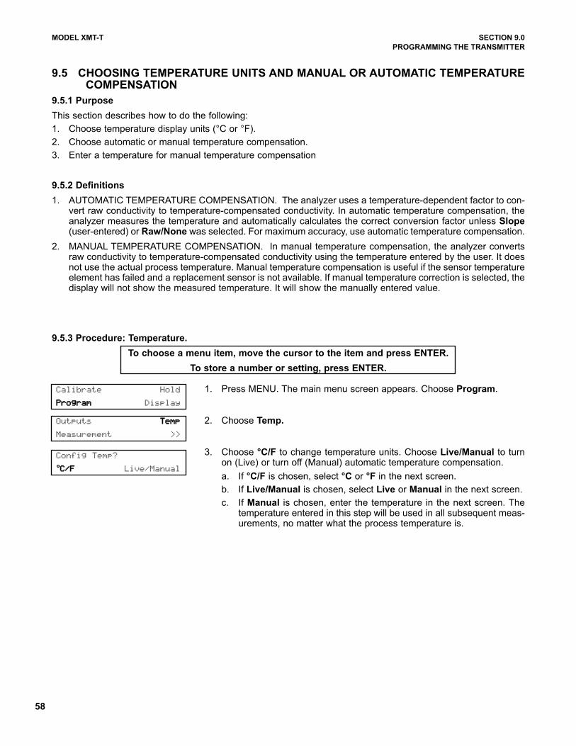
58
MODEL XMT-T SECTION 9.0
PROGRAMMING THE TRANSMITTER
9.5.3 Procedure: Temperature.
To choose a menu item, move the cursor to the item and press ENTER.
To store a number or setting, press ENTER.
1. Press MENU. The main menu screen appears. Choose Program.
2. Choose Temp.
3. Choose °C/F to change temperature units. Choose Live/Manual to turnon (Live) or turn off (Manual) automatic temperature compensation.
a. If °C/F is chosen, select °C or °F in the next screen.
b. If Live/Manual is chosen, select Live or Manual in the next screen.
c. If Manual is chosen, enter the temperature in the next screen. Thetemperature entered in this step will be used in all subsequent meas-urements, no matter what the process temperature is.
Calibrate Hold
PPrrooggrraamm Display
Config Temp?
°CC//FF Live/Manual
Outputs TTeemmpp
Measurement >>
9.5 CHOOSING TEMPERATURE UNITS AND MANUAL OR AUTOMATIC TEMPERATURECOMPENSATION
9.5.1 Purpose
This section describes how to do the following:
1. Choose temperature display units (°C or °F).
2. Choose automatic or manual temperature compensation.
3. Enter a temperature for manual temperature compensation
9.5.2 Definitions
1. AUTOMATIC TEMPERATURE COMPENSATION. The analyzer uses a temperature-dependent factor to con-vert raw conductivity to temperature-compensated conductivity. In automatic temperature compensation, theanalyzer measures the temperature and automatically calculates the correct conversion factor unless Slope(user-entered) or Raw/None was selected. For maximum accuracy, use automatic temperature compensation.
2. MANUAL TEMPERATURE COMPENSATION. In manual temperature compensation, the analyzer convertsraw conductivity to temperature-compensated conductivity using the temperature entered by the user. It doesnot use the actual process temperature. Manual temperature compensation is useful if the sensor temperatureelement has failed and a replacement sensor is not available. If manual temperature correction is selected, thedisplay will not show the measured temperature. It will show the manually entered value.
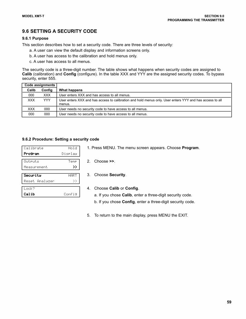
59
MODEL XMT-T SECTION 9.0
PROGRAMMING THE TRANSMITTER
Outputs Temp
Measurement >>>>
SSeeccuurriittyy HART
Reset Analyzer >>
9.6.2 Procedure: Setting a security code
Calibrate Hold
PPrrooggrraamm Display
Lock?
CCaalliibb Config
1. Press MENU. The menu screen appears. Choose Program.
2. Choose >>.
3. Choose Security.
4. Choose Calib or Config.
a. If you chose Calib, enter a three-digit security code.
b. If you chose Config, enter a three-digit security code.
5. To return to the main display, press MENU the EXIT.
9.6 SETTING A SECURITY CODE
9.6.1 Purpose
This section describes how to set a security code. There are three levels of security:
a. A user can view the default display and information screens only.
b. A user has access to the calibration and hold menus only.
c. A user has access to all menus.
The security code is a three-digit number. The table shows what happens when security codes are assigned toCalib (calibration) and Config (configure). In the table XXX and YYY are the assigned security codes. To bypasssecurity, enter 555.
Code assignments
Calib Config What happens
000 XXX User enters XXX and has access to all menus.
XXX YYY User enters XXX and has access to calibration and hold menus only. User enters YYY and has access to all menus.
XXX 000 User needs no security code to have access to all menus.
000 000 User needs no security code to have access to all menus.
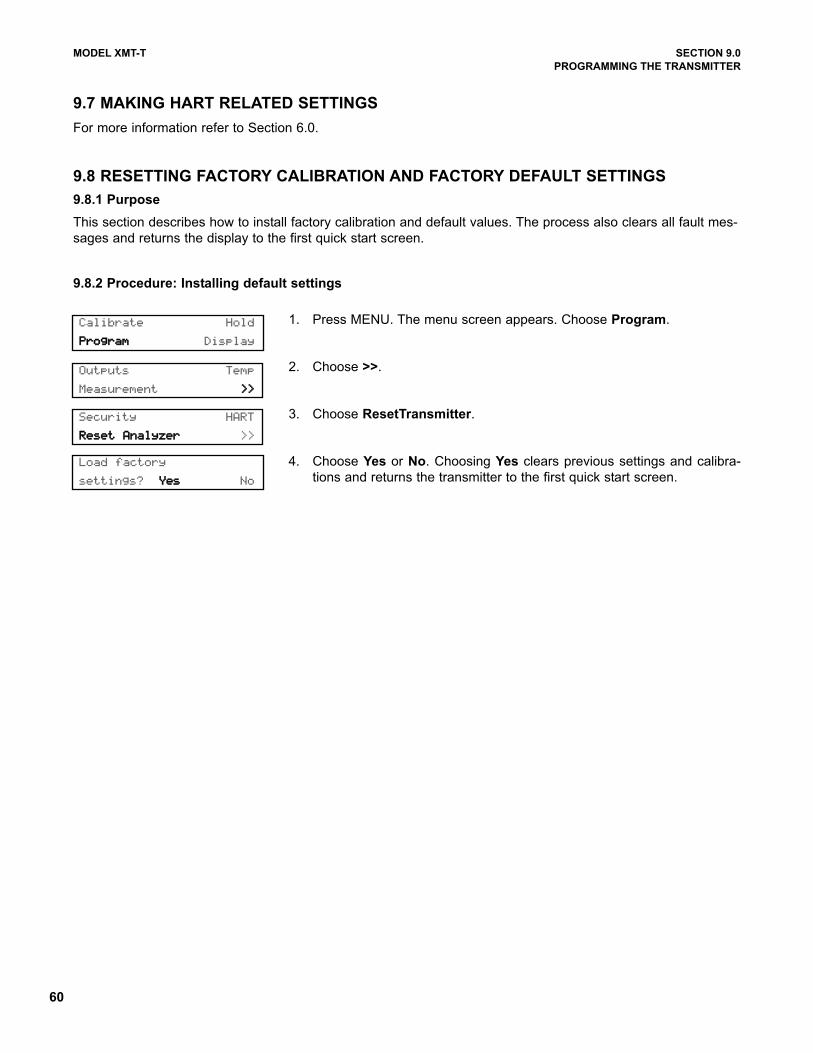
60
MODEL XMT-T SECTION 9.0
PROGRAMMING THE TRANSMITTER
9.7 MAKING HART RELATED SETTINGS
For more information refer to Section 6.0.
9.8 RESETTING FACTORY CALIBRATION AND FACTORY DEFAULT SETTINGS
9.8.1 Purpose
This section describes how to install factory calibration and default values. The process also clears all fault mes-
sages and returns the display to the first quick start screen.
9.8.2 Procedure: Installing default settings
Outputs Temp
Measurement >>>>
Security HART
RReesseett AAnnaallyyzzeerr >>
Calibrate Hold
PPrrooggrraamm Display
Load factory
settings? YYeess No
1. Press MENU. The menu screen appears. Choose Program.
2. Choose >>.
3. Choose ResetTransmitter.
4. Choose Yes or No. Choosing Yes clears previous settings and calibra-
tions and returns the transmitter to the first quick start screen.
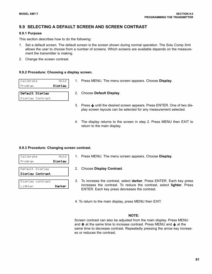
61
MODEL XMT-T SECTION 9.0
PROGRAMMING THE TRANSMITTER
DDeeffaauulltt DDiissppllaayy
Display Contrast
9.9.2 Procedure: Choosing a display screen.
Calibrate Hold
Program DDiissppllaayy
1. Press MENU. The menu screen appears. Choose Display.
2. Choose Default Display.
3. Press until the desired screen appears. Press ENTER. One of two dis-
play screen layouts can be selected for any measurement selected.
4. The display returns to the screen in step 2. Press MENU then EXIT to
return to the main display.
9.9 SELECTING A DEFAULT SCREEN AND SCREEN CONTRAST
9.9.1 Purpose
This section describes how to do the following:
1. Set a default screen. The default screen is the screen shown during normal operation. The Solu Comp Xmt
allows the user to choose from a number of screens. Which screens are available depends on the measure-
ment the transmitter is making.
2. Change the screen contrast.
Default Display
DDiissppllaayy CCoonnttrraasstt
Display contrast
Lighter DDaarrkkeerr
9.9.3 Procedure: Changing screen contrast.
Calibrate Hold
Program DDiissppllaayy
1. Press MENU. The menu screen appears. Choose Display.
2. Choose Display Contrast.
3. To increase the contrast, select darker. Press ENTER. Each key press
increases the contrast. To reduce the contrast, select lighter, Press
ENTER. Each key press decreases the contrast.
4. To return to the main display, press MENU then EXIT.
NOTE:
Screen contrast can also be adjusted from the main display. Press MENU
and at the same time to increase contrast. Press MENU and at the
same time to decrease contrast. Repeatedly pressing the arrow key increas-
es or reduces the contrast.
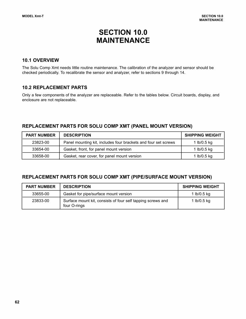
62
MODEL Xmt-T SECTION 10.0
MAINTENANCE
SECTION 10.0MAINTENANCE
REPLACEMENT PARTS FOR SOLU COMP XMT (PANEL MOUNT VERSION)
PART NUMBER DESCRIPTION SHIPPING WEIGHT
23823-00 Panel mounting kit, includes four brackets and four set screws 1 lb/0.5 kg
33654-00 Gasket, front, for panel mount version 1 lb/0.5 kg
33658-00 Gasket, rear cover, for panel mount version 1 lb/0.5 kg
REPLACEMENT PARTS FOR SOLU COMP XMT (PIPE/SURFACE MOUNT VERSION)
PART NUMBER DESCRIPTION SHIPPING WEIGHT
33655-00 Gasket for pipe/surface mount version 1 lb/0.5 kg
23833-00 Surface mount kit, consists of four self tapping screws and 1 lb/0.5 kg
four O-rings
10.1 OVERVIEW
The Solu Comp Xmt needs little routine maintenance. The calibration of the analyzer and sensor should be
checked periodically. To recalibrate the sensor and analyzer, refer to sections 9 through 14.
10.2 REPLACEMENT PARTS
Only a few components of the analyzer are replaceable. Refer to the tables below. Circuit boards, display, and
enclosure are not replaceable.
63
MODEL Xmt-T SECTION 11.0
THEORY OF OPERATION
SECTION 11.0THEORY OF OPERATION
11.1 CONDUCTIVITY / % CONCENTRATION
Liquids can only conduct electrical currents when they contain particles that carry charges. These particles are
called ions, and they are produced when acids, bases, and salts are mixed with water. The conductivity of a sub-
stance determines how well it can carry electrical currents and is used to indicate the concentration of acids, bases,
and salts in water.
Conductance is the reciprocal of resistance. The traditional unit of conductance is mho, a term representing the
reciprocal of ohm. Recently, the unit siemen has replaced the mho, but the amount of conductance is exactly the
same. Liquid water has relatively low conductivity, so measurements are expressed in millisiemens (.001 siemen)
or microsiemens (.000001 siemen), and abbreviated as mS or µS, respectively.
The Model Xmt-T conductivity transmitter is a device used to measure conductivity in most chemical processes.
Conductivity is a function of ion concentration, ionic charge, and ion mobility. Ions in water conduct current when
an electrical potential is applied across electrodes immersed in the solution.
Model Xmt-T is designed for use with inductive (toroidal) probes for measurement of high conductivity. Generally,
inductive probes are used for conductivity above 200 microsiemens. This sensor design is more sensitive to high-
level measurement and water solutions that tend to foul the sensor.
For % concentration measurement, the Model Xmt-T transmitter uses the measured temperature and absolute
conductivity and applies specific algorithms that have been developed for each of the substances available in the
instrument.
11.2 TEMPERATURE CORRECTION
The conductivity of an electrolyte solution depends strongly on temperature. To allow comparison among meas-
urements made at different temperatures, conductivity values are usually converted to the value at 25°C. The
Model Xmt-T performs the correction automatically with a user-programmable linear temperature coefficient
(slope). Temperature correction can also be turned off. If temperature correction is off, the Model Xmt-T displays
the raw or non-temperature corrected conductivity.
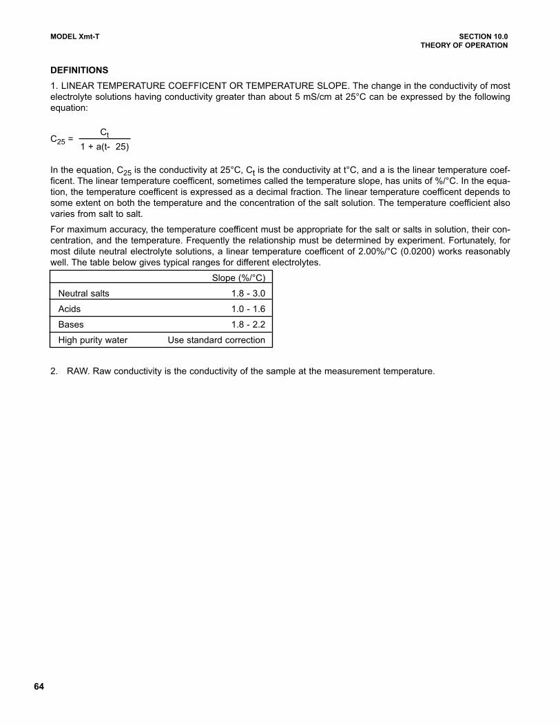
64
MODEL Xmt-T SECTION 10.0
THEORY OF OPERATION
DEFINITIONS
1. LINEAR TEMPERATURE COEFFICENT OR TEMPERATURE SLOPE. The change in the conductivity of most
electrolyte solutions having conductivity greater than about 5 mS/cm at 25°C can be expressed by the following
equation:
C25 =
In the equation, C25 is the conductivity at 25°C, Ct is the conductivity at t°C, and a is the linear temperature coef-
ficent. The linear temperature coefficent, sometimes called the temperature slope, has units of %/°C. In the equa-
tion, the temperature coefficent is expressed as a decimal fraction. The linear temperature coefficent depends to
some extent on both the temperature and the concentration of the salt solution. The temperature coefficient also
varies from salt to salt.
For maximum accuracy, the temperature coefficent must be appropriate for the salt or salts in solution, their con-
centration, and the temperature. Frequently the relationship must be determined by experiment. Fortunately, for
most dilute neutral electrolyte solutions, a linear temperature coefficent of 2.00%/°C (0.0200) works reasonably
well. The table below gives typical ranges for different electrolytes.
Slope (%/°C)
Neutral salts 1.8 - 3.0
Acids 1.0 - 1.6
Bases 1.8 - 2.2
High purity water Use standard correction
2. RAW. Raw conductivity is the conductivity of the sample at the measurement temperature.
Ct
1 + a(t- 25)
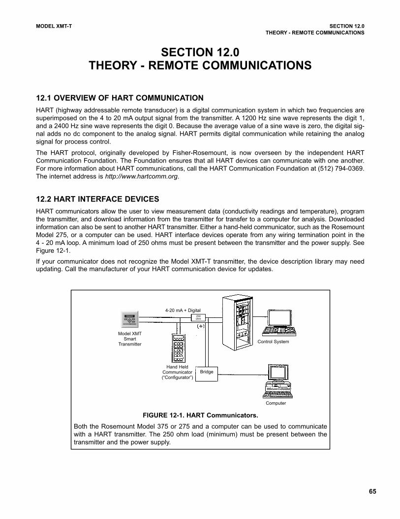
65
12.1 OVERVIEW OF HART COMMUNICATION
HART (highway addressable remote transducer) is a digital communication system in which two frequencies are
superimposed on the 4 to 20 mA output signal from the transmitter. A 1200 Hz sine wave represents the digit 1,
and a 2400 Hz sine wave represents the digit 0. Because the average value of a sine wave is zero, the digital sig-
nal adds no dc component to the analog signal. HART permits digital communication while retaining the analog
signal for process control.
The HART protocol, originally developed by Fisher-Rosemount, is now overseen by the independent HART
Communication Foundation. The Foundation ensures that all HART devices can communicate with one another.
For more information about HART communications, call the HART Communication Foundation at (512) 794-0369.
The internet address is http://www.hartcomm.org.
12.2 HART INTERFACE DEVICES
HART communicators allow the user to view measurement data (conductivity readings and temperature), program
the transmitter, and download information from the transmitter for transfer to a computer for analysis. Downloaded
information can also be sent to another HART transmitter. Either a hand-held communicator, such as the Rosemount
Model 275, or a computer can be used. HART interface devices operate from any wiring termination point in the
4 - 20 mA loop. A minimum load of 250 ohms must be present between the transmitter and the power supply. See
Figure 12-1.
If your communicator does not recognize the Model XMT-T transmitter, the device description library may needupdating. Call the manufacturer of your HART communication device for updates.
MODEL XMT-T SECTION 12.0
THEORY - REMOTE COMMUNICATIONS
SECTION 12.0THEORY - REMOTE COMMUNICATIONS
4-20 mA + Digital250 ohm
Control System
Computer
Model XMTSmart
Transmitter
BridgeHand Held
Communicator(“Configurator”)
FIGURE 12-1. HART Communicators.
Both the Rosemount Model 375 or 275 and a computer can be used to communicate
with a HART transmitter. The 250 ohm load (minimum) must be present between the
transmitter and the power supply.
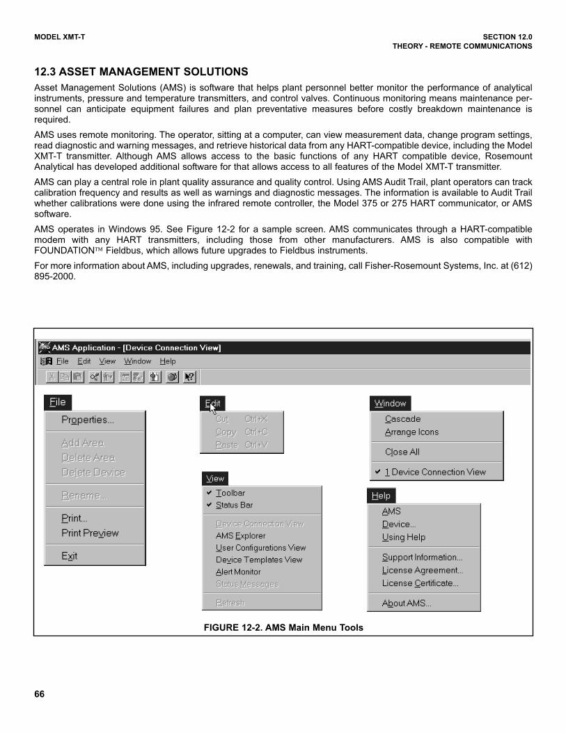
66
MODEL XMT-T SECTION 12.0
THEORY - REMOTE COMMUNICATIONS
12.3 ASSET MANAGEMENT SOLUTIONS
Asset Management Solutions (AMS) is software that helps plant personnel better monitor the performance of analyticalinstruments, pressure and temperature transmitters, and control valves. Continuous monitoring means maintenance per-sonnel can anticipate equipment failures and plan preventative measures before costly breakdown maintenance isrequired.
AMS uses remote monitoring. The operator, sitting at a computer, can view measurement data, change program settings,read diagnostic and warning messages, and retrieve historical data from any HART-compatible device, including the ModelXMT-T transmitter. Although AMS allows access to the basic functions of any HART compatible device, RosemountAnalytical has developed additional software for that allows access to all features of the Model XMT-T transmitter.
AMS can play a central role in plant quality assurance and quality control. Using AMS Audit Trail, plant operators can trackcalibration frequency and results as well as warnings and diagnostic messages. The information is available to Audit Trailwhether calibrations were done using the infrared remote controller, the Model 375 or 275 HART communicator, or AMSsoftware.
AMS operates in Windows 95. See Figure 12-2 for a sample screen. AMS communicates through a HART-compatiblemodem with any HART transmitters, including those from other manufacturers. AMS is also compatible withFOUNDATION™ Fieldbus, which allows future upgrades to Fieldbus instruments.
For more information about AMS, including upgrades, renewals, and training, call Fisher-Rosemount Systems, Inc. at (612)895-2000.
FIGURE 12-2. AMS Main Menu Tools
67
MODEL XMT-T SECTION 13.0RETURN OF MATERIAL
SECTION 13.0
RETURN OF MATERIAL
13.1 GENERAL.
To expedite the repair and return of instruments, proper
communication between the customer and the factory
is important. Call 1-949-757-8500 for a Return
Materials Authorization (RMA) number.
13.2 WARRANTY REPAIR.
The following is the procedure for returning instru-
ments still under warranty:
1. Call Rosemount Analytical for authorization.
2. To verify warranty, supply the factory sales order
number or the original purchase order number. In
the case of individual parts or sub-assemblies, the
serial number on the unit must be supplied.
3. Carefully package the materials and enclose your
“Letter of Transmittal” (see Warranty). If possible,
pack the materials in the same manner as they
were received.
4. Send the package prepaid to:
Emerson Process Management
Liquid Division
2400 Barranca Parkway
Irvine, CA 92606
Attn: Factory Repair
RMA No. ____________
Mark the package: Returned for Repair
Model No. ____
13.3 NON-WARRANTY REPAIR.
The following is the procedure for returning for repair
instruments that are no longer under warranty:
1. Call Rosemount Analytical for authorization.
2. Supply the purchase order number, and make
sure to provide the name and telephone number
of the individual to be contacted should additional
information be needed.
3. Do Steps 3 and 4 of Section 13.2.
NOTE
Consult the factory for additional informa-
tion regarding service or repair.

68
WARRANTY
Goods and part(s) (excluding consumables) manufactured by Seller are warranted to be free from defects in workman-
ship and material under normal use and service for a period of twelve (12) months from the date of shipment by Seller.
Consumables, pH electrodes, membranes, liquid junctions, electrolyte, O-rings, etc. are warranted to be free from defects
in workmanship and material under normal use and service for a period of ninety (90) days from date of shipment by Seller.
Goods, part(s) and consumables proven by Seller to be defective in workmanship and / or material shall be replaced or
repaired, free of charge, F.O.B. Seller's factory provided that the goods, parts(s), or consumables are returned to Seller's
designated factory, transportation charges prepaid, within the twelve (12) month period of warranty in the case of goods
and part(s), and in the case of consumables, within the ninety (90) day period of warranty. This warranty shall be in effect
for replacement or repaired goods, part(s) and consumables for the remaining portion of the period of the twelve (12)
month warranty in the case of goods and part(s) and the remaining portion of the ninety (90) day warranty in the case of
consumables. A defect in goods, part(s) and consumables of the commercial unit shall not operate to condemn such com-
mercial unit when such goods, parts(s) or consumables are capable of being renewed, repaired or replaced.
The Seller shall not be liable to the Buyer, or to any other person, for the loss or damage, directly or indirectly, arising
from the use of the equipment or goods, from breach of any warranty or from any other cause. All other warranties,
expressed or implied are hereby excluded.
IN CONSIDERATION OF THE STATED PURCHASE PRICE OF THE GOODS, SELLER GRANTS ONLY THE ABOVE
STATED EXPRESS WARRANTY. NO OTHER WARRANTIES ARE GRANTED INCLUDING, BUT NOT LIMITED TO,
EXPRESS AND IMPLIED WARRANTIES OF MERCHANTABILITY AND FITNESS FOR A PARTICULAR PURPOSE.
RETURN OF MATERIAL
Material returned for repair, whether in or out of warranty, should be shipped prepaid to:
Emerson Process Management
Liquid Division
2400 Barranca Parkway
Irvine, CA 92606
The shipping container should be marked:
Return for Repair
Model _______________________________
The returned material should be accompanied by a letter of transmittal which should include the following information
(make a copy of the "Return of Materials Request" found on the last page of the Manual and provide the following there-
on):
1. Location type of service, and length of time of service of the device.
2. Description of the faulty operation of the device and the circumstances of the failure.
3. Name and telephone number of the person to contact if there are questions about the returned material.
4. Statement as to whether warranty or non-warranty service is requested.
5. Complete shipping instructions for return of the material.
Adherence to these procedures will expedite handling of the returned material and will prevent unnecessary additional
charges for inspection and testing to determine the problem with the device.
If the material is returned for out-of-warranty repairs, a purchase order for repairs should be enclosed.

Credit Cards for U.S. Purchases Only.
The right people,the right answers,right now. ON-LINE ORDERING NOW AVAILABLE ON OUR WEB SITE
http://www.raihome.com
Specifications subject to change without notice.
Emerson Process Management
Liquid Division2400 Barranca Parkway
Irvine, CA 92606 USA
Tel: (949) 757-8500
Fax: (949) 474-7250
http://www.raihome.com
© Rosemount Analytical Inc. 2006