Embed Size (px)
Citation preview

Revision H Issued: 12/11
Model SG-100 Plasma Spray Gun Operator’s Manual
Manual Part Number: 05001760

EC Declaration of Conformity
We, Praxair Surface Technologies, 146 Pembroke Road, Concord, NH 03301 USA, declare under sole responsibility that the Model SG-100 Plasma Spray Gun to which this declaration relates is in conformity with the relevant provisions of the following standard(s) or other document(s): Electromagnetic Compatibility Directive 2004/108/EC EN 60974-10:2003: CISPR 11:1997, 5.1.2, Table 2A CISPR 11:1997, 5.2.2, Table 3 EN60974-10:2003: EN 61000-4-2:1995/A1:1998/A2:2001 EN 61000-4-4:2004, EN 61000-4-6 :1996/A1:2001 EN 61000-4-11:2004, Machinery Directive(s) 2006/42/EC, EU Low Voltage Directive(s) 2006/95/EC EN 60204-1:2006 We hereby declare that the equipment specified above conforms to the above directive(s) and standard(s).
Signature:
Full Name: Stephen Ford Position: Engineering Manager
Praxair Surface Technologies, Inc. 146 Pembroke Road Concord, NH 03301 (603) 224-9585 phone (603) 225-4342 fax
DISCLAIMERS
All information referred to and/or included in this manual is current as of the original issue date of this manual. Praxair Surface Technologies, Inc. makes no warranty or representation with respect to the accuracy of the information contained therein nor with respect to the suitability of the use of such information outside Praxair Surface Technologies, neither does Praxair Surface Technologies assume responsibility for any injury or damage which may result, directly or indirectly, from the use of such information.
The information contained herein is offered for use by technically qualified personnel at their discretion and risk without warranty of any kind. Praxair Surface Technologies is constantly improving its products, and specifications are subject to change without notice.
This manual could include technical inaccuracies or typographical errors. Changes are made periodically to the information herein; these changes will be incorporated in subsequent revisions of the manual. Praxair Surface Technologies reserves the right to make improvements and/or changes to the product(s) and/or programs described in this manual at any time and without notice. Illustrations are meant to be representative of, but not exact duplicates of, existing equipment.
BUSINESS CONFIDENTIAL
THIS MANUAL CONTAINS CONFIDENTIAL AND PROPRIETARY INFORMATION OF PRAXAIR SURFACE TECHNOLOGIES. THIS INFORMATION IS PROVIDED IN CONFIDENCE SOLELY FOR USE WITH OUR MODEL SG-100 PLASMA SPRAY GUN. THIS MANUAL MAY NOT BE REPRODUCED IN ANY FORM OR ITS CONTENTS DISCLOSED TO THIRD PARTIES WITHOUT THE PRIOR WRITTEN CONSENT OF PRAXAIR SURFACE TECHNOLOGIES.
TRADEMARK INFORMATION
Praxair and the Flowing Airstream design are trademarks or registered trademarks of Praxair
Technology, Inc. in the United States and other countries.
TAFA and the TAFA Flame design are trademarks or registered trademarks of Praxair S.T.
Technology, Inc. in the United States and other countries.
Other trademarks used herein are trademarks or registered trademarks of their respective owners.
Praxair Surface Technologies, Inc. Printed in the United States of America. Copyright © 2011 Praxair S.T. Technology, Inc.

Model SG-100 Plasma Spray Gun Operator’s Manual
_____________________________________________________________________________________________________________________
Issued: 12/11 Page iii
Safety First Read This Before Using Thermal Spray Equipment
WARNING
Read and understand operator’s manual before using this machine. Failure to follow operating instructions could result in injury or damage to equipment.
Thermal spraying is powerful technology. Do not use equipment carelessly or without observing safe practices. Be safe! Learn the recommended procedures and standards. Failure to follow recommended procedures and standards can result in severe injury to people and damage to equipment.
Who should use Thermal Spray Equipment?
Use the equipment only if you have been trained fully in safely using it. Do not allow untrained persons to install, operate, or maintain the equipment.
Understand what to do before you do it!
Make sure that you have read and understand the contents of this manual - especially the safety guidelines and operating procedures - before installing, operating, or maintaining this equipment. Contact a Factory Representative if you do not fully understand any guidelines or instructions.
Model SG-100 Plasma Spray Gun Operator’s Manual
_____________________________________________________________________________________________________________________
Issued: 12/11 Page iv
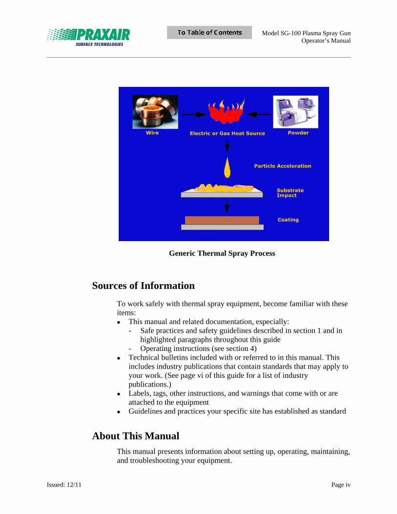
Generic Thermal Spray Process
Sources of Information
To work safely with thermal spray equipment, become familiar with these items: This manual and related documentation, especially:
- Safe practices and safety guidelines described in section 1 and in highlighted paragraphs throughout this guide
- Operating instructions (see section 4) Technical bulletins included with or referred to in this manual. This
includes industry publications that contain standards that may apply to your work. (See page vi of this guide for a list of industry publications.)
Labels, tags, other instructions, and warnings that come with or are attached to the equipment
Guidelines and practices your specific site has established as standard
About This Manual
This manual presents information about setting up, operating, maintaining, and troubleshooting your equipment.
Model SG-100 Plasma Spray Gun Operator’s Manual
_____________________________________________________________________________________________________________________
Issued: 12/11 Page v
Conventions
Throughout this manual, certain words and symbols are used to draw your attention to important information. These symbols and words have the following meaning:
Praxair Surface Technologies
RECOMMENDS
A procedure or setting that will produce optimum results
Information that can help to operate the equipment more effectively.
Refer to the manual before doing any maintenance.
Wear respirator.
Risk of eye injury. Eye protection required.
Wear opaque eye protection.
Wear protective clothing, gloves.
Wear hearing protection.
Pressure Relief
WARNING
This device is designed for use with Argon and/or Nitrogen gas.
The gases used with this device pose and asphyxiation hazard.
USE THIS DEVICE ONLY IN A WELL VENTILATED AREA.

Model SG-100 Plasma Spray Gun Operator’s Manual
_____________________________________________________________________________________________________________________
Issued: 12/11 Page vi
WARNING
PERSONAL INJURY HAZARD:
Use caution when handling the powder feeder, feed lines and fittings. There is a possibility of static electricity discharge from the powder feed system which could result in significant discomfort or injury.
HAZARD
Hazards that can result in minor or major damage to equipment, bodily injury to people, and how to prevent such hazards.
EXPLOSION HAZARD
ELECTRIC SHOCK HAZARD
FIRE HAZARD
HIGH TEMPERATURE HAZARD
ELECTROMAGNETIC FIELDS HAZARD
LIGHT EMISSION HAZARD
People with Heart Pacemakers Not Allowed
Model SG-100 Plasma Spray Gun Operator’s Manual
_____________________________________________________________________________________________________________________
Issued: 12/11 Page vii
Related Publications
Information that can help
OSHA (Occupational Safety and Health Administration) establishes mandatory federal safety regulations. For information about the regulations, refer to OSHA Standards, Code of Federal Regulations, Title 29, Part 1910. Handling compressed gas is among the safety hazards associated with thermal spraying. ANSI/AWS Z49.1, Safety in Welding and Cutting and the Williams-Steiger Occupational Safety and Health Act of 1970 (84 Stat. 1943) cover safe handling of compressed gases. More recently, the Resource Conservation and Recovery Act (RCRA), dealing with the disposal of toxic wastes, potentially affects the thermal spray industry. Occupational Safety and Health Act Standards (29CFR 1910), available from the Superintendent of Documents, U.S. Government Printing Office. Ventilation, Occupational Safety and Health Standard OSHA 1910.94, available from the Occupational Safety and Health Administration. Safety in Welding and Cutting, AWS/ANSI Z49.1, available from the American Welding Society. Environmental, Health, and Safety Guidelines, available from TSS an affiliate society of ASM International (ASM TSS). Requirements for Personal Eye and Face Protection, ANSI Z87.1-2003, available from the American National Standards Institute. Standard Practices for Respiratory Protection, ANSI Z88.2, available from the American National Standards Institute. Safety Requirements for Industrial Head Protection, ANSI Z89.1, available from the American National Standards Institute. National Electrical Code, NFPA 70-2011, available from the National Fire Protection Association, updated annually. Safe Handling of Compressed Gases, CGA Pamphlet P-1, available from the Compressed Gas Association.
Model SG-100 Plasma Spray Gun Operator’s Manual
_____________________________________________________________________________________________________________________
Issued: 12/11 Page viii
Oxygen, CGA Pamphlet G-4, available from the Compressed Gas Association. NFPA 50 Bulk Oxygen Systems at Consumer Sites, available from the National Fire Protection Association. NFPA 55 Compressed Gases and Cryogenic Fluids Code, available from the National Fire Protection Association. NFPA 30 Flammable and Combustible Liquids Code, available from the National Fire Protection Association. Recommended Safe Practices for the Preparation for Welding and Cutting of Containers That Have Held Hazardous Substances, ANSI/AWS F3.2, available from the American Welding Society. Safety Release Device Standards - Cylinders for Compressed Gases, CGA Pamphlet S1.1-1963 and 1965 and S1.2-1963, available from the Compressed Gas Association. Power and Process Piping Package, ANSI B31.1, available from the American National Standards Institute. Acetylene, CGA Pamphlet G-1, available from the Compressed Gas Association. NFPA 51Standard for the Design and Installation of Oxygen-Fuel Gas Systems for Welding, Cutting, and Allied Processes, available from the National Fire Protection Association. NFPA 51B Standard for Fire Prevention During Welding, Cutting and Other Hot Work, available from the National Fire Protection Association. ANSI/NFPA 58 Liquefied Petroleum Gas Code, available from the National Fire Protection Association. Industrial Ventilation: A Manual of Recommended Practice ACGIH (25th Ed., 2004) American National Standard for Hand Protection Selection Criteria, 105-2011, available from the International Safety Equipment Association.
Model SG-100 Plasma Spray Gun Operator’s Manual
_____________________________________________________________________________________________________________________
Issued: 12/11 Page ix
Table of Contents
Read This Before Using Thermal Spray Equipment ................................................................ iii Section 1 Safety Guidelines ....................................................................................................1
1.1 Reminder: Safety First! .......................................................................................................... 1 1.2 General Guidelines ................................................................................................................. 2 1.3 Fire Protection and Prevention .............................................................................................. 2 1.3.1 Keep Work Areas Clean .......................................................................................... 2 1.3.2 High Temperatures ................................................................................................... 2 1.3.3 Hazardous Materials ................................................................................................ 3 1.4 Safe Operating Conditions ..................................................................................................... 3 1.4.1 Compressed Gas Cylinders ...................................................................................... 3 1.4.2 Flow Meters ............................................................................................................. 4 1.4.3 Compressed Air ....................................................................................................... 5 1.4.4 Flame Spray and HVOF Equipment ........................................................................ 5 1.4.5 Plasma and Arc Spray Equipment ............................................................................ 6 1.4.6 Abrasive Blast Machine ........................................................................................... 7 1.4.7 Handling and Manipulating Equipment ................................................................... 7 1.5 Protecting Workers ................................................................................................................. 8 1.5.1 Eye Protection .......................................................................................................... 8 1.5.2 Respiratory Protection .............................................................................................. 9 1.5.3 Noise Protection ..................................................................................................... 10 1.5.3.1 Noise and Noise Level ......................................................................... 10 1.5.3.2 Noise Duration ..................................................................................... 11 1.5.3.3 Hearing Protection ............................................................................... 12 1.5.4 Protective Clothing ................................................................................................ 14 1.5.5 Confined Spaces ..................................................................................................... 15 1.5.5.1 Rapid Emergency Exit ......................................................................... 15 1.5.5.2 Factors to Consider .............................................................................. 15 1.6 Toxic Material ...................................................................................................................... 18 1.6.1 Beryllium and Lead ................................................................................................ 18 1.6.2 Cadmium ................................................................................................................ 18 1.6.3 Cobalt, Chromium, and Tellurium ......................................................................... 18 1.6.4 Tin and Zinc ........................................................................................................... 19 1.6.5 Solvents .................................................................................................................. 19 1.6.6 Threshold Limit Values ......................................................................................... 19 1.7 Safety Standards ................................................................................................................... 20
Section 2 Equipment Description ........................................................................................21
2.1 Plasma Spray Process Description ....................................................................................... 21 Figure 2-1 SG-100 Specifications ........................................................................................ 21 Figure 2-2 SG-100 Gun Dimensions .................................................................................... 22 2.2 SG-100 Gun Description ...................................................................................................... 22 2.3 Water Cooling Requirements ............................................................................................... 22 2.4 Optional Items ...................................................................................................................... 24 A. Adapters .......................................................................................................................... 24 B. Extension Conversions .................................................................................................... 24 C. Y-Splitter ......................................................................................................................... 24
Model SG-100 Plasma Spray Gun Operator’s Manual
_____________________________________________________________________________________________________________________
Issued: 12/11 Page x
D. External Powder Injection Adapter ................................................................................. 24 E. Air Jet Kit ........................................................................................................................ 24 F. Manipulator Adapters ....................................................................................................... 24
Section 3 Installation ............................................................................................................25 3.1 Receiving-Handling ............................................................................................................. 25 3.2 SG-100 Gun Installation ....................................................................................................... 25 Figure 3-1 SG-100 Installation ............................................................................................. 26 3.3 SG-100 AIR JET (Optional) ................................................................................................. 26 Figure 3-2 SG-100 Air Jet Installation ................................................................................. 27 3.4 SG-100 Gun Test Instructions .............................................................................................. 27
Section 4 Operation ..............................................................................................................29 Note for SG-100 Plasma Gun Users ..................................................................................... 30
4.1 Plasma Spray Shop Notes ..................................................................................................... 31 A. Choice of Proper Electrodes ............................................................................................ 31 B. Powder Sprayability......................................................................................................... 31 C. Surface Preparation .......................................................................................................... 32 C-1. Surface Cleanliness ........................................................................................ 32 C-2. Grit Blasting ................................................................................................... 32 C-3. Masking .......................................................................................................... 33 D. Arc Gas Recommendations ............................................................................................. 33 E. Proper Operating Parameters ........................................................................................... 34 F. Powder Injection .............................................................................................................. 35 G. Powder Pulsing ................................................................................................................ 35 G-1. Hose Dress ..................................................................................................... 35 G-2. Gas Leaks ....................................................................................................... 35 G-3. Feeder Main Bearing ..................................................................................... 35 G-4. Shaft Coupling ............................................................................................... 36 G-5. Static .............................................................................................................. 36 G-6. Powder Tube .................................................................................................. 36 G-7. Powder Tube O-ring ...................................................................................... 37 G-8. Carrier Gas Flow ............................................................................................ 37 G-9. Tamper Assembly .......................................................................................... 37 G-10. Wet Powder.................................................................................................. 37 G-11. Improperly Sized Powder ............................................................................ 37 G-12. O-ring Lube ................................................................................................. 37 G-13. System Time Constants ................................................................................ 37 H. Traverse Speed/Pitch ....................................................................................................... 38 I. Substrate Cooling .............................................................................................................. 38 4.2 SG-100 Plasma Gun Spray Parameters ................................................................................ 39
Section 5 Maintenance .........................................................................................................41
5.1 Plasma-arc Starting Problems .............................................................................................. 41 5.2 Anode Removal and Maintenance ........................................................................................ 41 Figure 5-1 Anode Removal Tool Insertion ........................................................................... 42 Figure 5-2 Anode Removal .................................................................................................. 42 Figure 5-3 SG-100 Gun, exploded view ............................................................................... 43 Figure 5-4 SG-100 Gun, assembled view ............................................................................. 44 5.3 Cathode Removal & Maintenance ........................................................................................ 45 Figure 5-5 Cathode Removal Tool ....................................................................................... 45 5.4 Complete SG-100 Disassembly & Maintenance .................................................................. 46
Model SG-100 Plasma Spray Gun Operator’s Manual
_____________________________________________________________________________________________________________________
Issued: 12/11 Page xi
5.5 Complete SG-100 Gun Reassembly ..................................................................................... 47
Section 6 Parts List ...............................................................................................................49
6.1 SG-100 Plasma Spray gun Assembly ................................................................................... 49 Figure 6-1 SG-100 Plasma Spray Gun Assembly ................................................................ 50 SG-100 Plasma Spray Gun Assembly Parts List .................................................................. 51 6.2 SG-100 Electrode Gas Injector Configurations .................................................................... 52 Standard Hardware (non-vortex) ............................................................................ 52 Subsonic Optional Hardware ................................................................................. 52 Mach I Optional Hardware..................................................................................... 53 Mach II Optional Hardware ................................................................................... 53 6.3 Optional Items ...................................................................................................................... 54 6.4 SG-100 Hoses and Cables .................................................................................................... 55
Model SG-100 Plasma Spray Gun Operator’s Manual
_____________________________________________________________________________________________________________________
Issued: 10/11 Page 1
Section 1 Safety Guidelines
This section covers potential hazards and safety issues associated with thermal spraying, preparing for its use, and its finishing processes. Subjects include:
Fire prevention and protection Safe operating conditions Flame spray and HVOF equipment Plasma and arc equipment Abrasive blast machines Safe operation of the equipment Worker’s protection Ventilation Toxic material handling Relevant safety standards
1.1 Reminder: Safety First!
Thermal spraying equipment is very powerful. Do not use equipment carelessly or without observing safe practices. Be safe! Learn the recommended procedures and standards. Failure to follow recommended procedures and standards can result in severe damage to equipment and injury to people.
Use the equipment only if you have been trained fully in its safe operation. Do not allow untrained persons to install, operate, maintain, or troubleshoot the equipment.
Make sure that you have read and understand the contents of this manual - especially the safety guidelines and operating procedures - before installing, operating, or maintaining this equipment. Contact a Factory Representative if you do not fully understand any guidelines or instructions.
Model SG-100 Plasma Spray Gun Operator’s Manual
_____________________________________________________________________________________________________________________
Issued: 10/11 Page 2
1.2 General Guidelines
All persons concerned with thermal spraying must know and understand these safe practices and the safety regulations contained in established standards. Pertinent established standards are listed in "Related Publications" on page vii. Information presented in this manual and on various labels, tags, and plates on the unit pertains to equipment design, installation, operation, maintenance, and troubleshooting that should be read, understood, and followed for the safe and effective use of this equipment. The installation, operation, maintenance, and troubleshooting of thermal spray equipment requires practices and procedures that ensure personal safety and the safety of others. Therefore, this equipment is to be installed, operated, and maintained by qualified persons as specified in this manual and in accordance with all applicable codes such as, but not limited to, those listed in section 1, and the corresponding sections of the manual. You should thoroughly understand and comply with local, state, and federal (OSHA) health standards, especially when handling toxic materials.
1.3 Fire Protection and Prevention
1.3.1 Work Areas
Keep the work area clean! Avoid accumulating metal dusts. Inspect rafters, tops of booths, and floor cracks for dust accumulation. NEVER store paper, wood, oily rags, or cleaning solvents within the spray room or enclosure.
1.3.2 High Temperatures
Thermal spraying operations generate extremely high temperatures. NEVER point thermal spray equipment at any person or flammable material.
Model SG-100 Plasma Spray Gun Operator’s Manual
_____________________________________________________________________________________________________________________
Issued: 10/11 Page 3
1.3.3 Hazardous Materials
Toxic Wastes
Preparations for thermal spraying, the process itself, or subsequent finishing operations may generate toxic materials. Dispose of them according to the EPA Resource Conservation and Recovery Act (RCRA).
Flammable Solvents and Sealer Bases
Certain de-greasing solvents and sealer bases are flammable and require special use, handling, and storage precautions in and around the thermal spray area.
Metal Dusts and Powders
Treat airborne metal dusts, finely divided solids, or accumulations as explosives. Minimize the danger from dust explosions by providing adequate ventilation in spray booths. Install a cartridge-type dry dust collection system to collect spray dust.
1.4 Safe Operating Conditions
1.4.1 Compressed Gas Cylinders
Always comply with local, state, municipal, and federal regulations regarding compressed gas cylinder storage and follow recommendations in ANSI/AWS Z49.1, Safety in Welding and Cutting; CGA Pamphlet P-1, Safe Handling of Compressed Gases; NFPA 55, Compressed & Liquefied Gases in Portable Cylinders; NFPA 51, Oxygen-Fuel Gas Systems in Welding and Cutting; and NFPA 51B Standard for Fire Prevention in the Use of Cutting & Welding Processes. Improper storage, handling, and use of gas cylinders Creates A Safety Hazard. If the site plan includes manifolding cylinders to permit longer spray times before changeover, follow ANSI/AWS Z49.1 recommendations in designing the plan. NEVER use oil or grease on oxygen equipment. Use ONLY special oxidation- resistant lubricants. Consult the equipment manufacturers or a qualified dealer for more information.
Model SG-100 Plasma Spray Gun Operator’s Manual
_____________________________________________________________________________________________________________________
Issued: 10/11 Page 4
Be sure the work area is adequately ventilated before opening any gas valves. Drain the regulator of gas and release the regulator adjusting screw before SLOWLY opening the cylinder valves. ALWAYS stand away from the direction of force when opening cylinder valves.
Install pressure reducing regulators in accordance with ANSI/AWS Z49.1. Use only the appropriate regulator for each gas cylinder: USE ONLY ACETYLENE REGULATORS ON ACETYLENE TANKS OR MANIFOLD SYSTEMS. Always use the correct size wrench to connect the regulator to the cylinder valve outlet; NEVER force or overtighten a connection. NEVER use oil or grease on a regulator.
1.4.2 Flow Meters
Install and use flow meters in accordance with ANSI/AWS Z49.1. Avoid unsafe operating conditions and ensure proper flame balance by installing backflow prevention devices in conjunction with the flow meters. Place a protective shield on flow meters with glass tubes. Install and use hose and hose connections according to ANSI/AWS Z49.1 and the Specification for Rubber Welding Hose published by the Rubber Manufacturer’s Association and the CGA. Handle hoses carefully to avoid damage. Use hoses only in the applications for which they are designed. Blow out hoses to remove any dust. Avoid any ignition sources. Turn regulator adjusting screws slowly to prevent surges that may crack or burst flow meter tubes. Overtightening can collapse the nipple nose, so NEVER OVERTIGHTEN the connecting nuts on pressure reducing regulators and flow meters. If a fitting does not seal without undue force, replace it. NEVER use a flame to check for gas leaks. Use soapy water to check all hose connections for leaks. Soapy water provides a safer, more sensitive test. If any connections leak, depressurize, open the connection, clean the sealing surfaces and threads, re-assemble, pressurize, and test for leaks. If a leak persists, depressurize the system.
Model SG-100 Plasma Spray Gun Operator’s Manual
_____________________________________________________________________________________________________________________
Issued: 10/11 Page 5
EXPLOSION HAZARD:
NEVER USE LEAKING THERMAL SPRAY EQUIPMENT.
Place a “Danger Do Not Operate” tag on the defective equipment to alert others to the unsafe condition.
Obstructed gas lines caused by defective hoses, collapsed hose stems, or dirt in the gun head gas passages or nozzle jets require excessive gas pressure to obtain proper gas flow. If required oxygen and fuel gas pressure are more than 3 psi (0.2 bar) over the recommended pressure, check for a fouled nozzle or incorrect air cap. Low pressures often indicate a serious leak. Shut down the equipment and correct the condition before restarting the system.
EXPLOSION HAZARD:
Acetylene pressures exceeding 15 psi (1.03 bar) may cause the gas to detonate. If this pressure of 15 psi (1.03 bar) is insufficient, use another fuel gas.
1.4.3 Compressed Air
Always refer to gases by their proper names to avoid confusion. Never use compressed air, oxygen, or fuel gas to clean clothing. For thermal spraying or blasting operations, use compressed air only at recommended pressures. Keep the air line free of oil and moisture. Consult an equipment dealer for filter and after-cooler recommendations.
1.4.4 Flame Spray and HVOF Equipment
Thoroughly read and understand this manual and familiarize all operators with gun operation before lighting the gun. Maintain guns according to recommendations.
PERSONAL INJURY (BURN) HAZARD:
Using a match to light a flame spraying gun can result in serious injury. Use a friction lighter, pilot light, or arc ignition instead.
Model SG-100 Plasma Spray Gun Operator’s Manual
_____________________________________________________________________________________________________________________
Issued: 10/11 Page 6
Properly seating and lubricating the gun's oxygen, fuel gas, and compressed air valves helps the gun operate freely and shut off completely.
Extinguish gun backfires as quickly as possible.
Determine the cause of gun backfires or blowouts BEFORE relighting.
When you have completed spray operations, when you are shutting down the equipment, or when you leave the equipment unattended, release all gas pressure from the regulators and hoses.
EXPLOSION OR FIRE HAZARD:
NEVER hang a flame spraying gun or its hoses on regulators or cylinder valves.
1.4.5 Plasma and Arc Spray Equipment
Plasma and arc spray equipment differ from flame and HVOF equipment. They use high voltages and amperages that represent an electrical hazard. Train operators how to use the equipment safely before they actually use it. Specifically, ensure that operators know and understand all the operating and safety recommendations in the operator manuals. Always observe standard safety precautions for electrical equipment and operate in accordance with ANSI/AWS Z49.1. Frequently clean arc guns and power supplies to prevent metal dust accumulation that causes electrical short circuits. Properly insulate or ground the wire feed units used with the arc spray equipment. If the gun is suspended, insulate or ground the suspension hook. Ground or insulate all exposed plasma gun electrodes and cable connections. Interconnect all ground cables. Periodically inspect cables, insulation, hoses, and gas lines. All pushbuttons, pilot lights, plugs, and cables should be intact and meet ANSI/NFPA 70-2011, National Electrical Code standards. Repair or replace faulty equipment at once. Never adjust, clean, or repair any part of the power supply, console, or gun without first disengaging the entire system, including the power supply.
Model SG-100 Plasma Spray Gun Operator’s Manual
_____________________________________________________________________________________________________________________
Issued: 10/11 Page 7
Avoid contact between any ungrounded portion of the plasma or arc gun and the spray booth or chamber. Electrically isolate plasma guns and nozzles from support brackets to prevent stray high frequency current from damaging other electrical equipment and controls.
1.4.6 Abrasive Blast Machine
Maintain and inspect abrasive blast machines according to manufacturer's instructions. Remove and repair or replace worn parts as needed. Do not exceed recommended air pressure in the blast tank. Keep blast hoses as straight as possible between the blast machine and blasting area. Sharp hose bends cause excessive friction and wear that can lead to a blowout at those points. If hoses must be curved around an object, use long radius curves. Store blast hoses in cool, dry areas. Be sure blast hose controls function properly. They should require continuous pressure on the activating lever for operation. Releasing the lever should cause the system to shut off (dead man control).
PERSONAL INJURY:
NEVER point a blast nozzle at a person.
Most blasting operations require respiratory protection for the operator. Select, operate, and maintain the protective device according to ANSI Z88.2, Standard Practices for Respiratory Protection, described in section 1.5.2.
1.4.7 Handling and Manipulating Equipment
Most thermal spray and blasting applications require rotation or other manipulation of the part being worked on. Some handling equipment can impart high rotational speeds to parts being coated. Affix and balance parts when necessary. Provide protection for the operator in case a rotating part becomes airborne. Never leave operating equipment unattended.
Model SG-100 Plasma Spray Gun Operator’s Manual
_____________________________________________________________________________________________________________________
Issued: 10/11 Page 8
1.5 Protecting Workers
The general requirements for the protection of thermal spraying operators and welders are the same as those published in ANSI/AWS Z49.1, Safety in Welding and Cutting; ANSI Z87.1, Standard Practices for Occupational and Educational Eye and Face Protection; ANSI Z88.2, Standard Practices for Respiratory Protection; and ANSI Z89.1, Standard Practices for Industrial Head Protection with Low Voltage Hazards.
1.5.1 Eye Protection
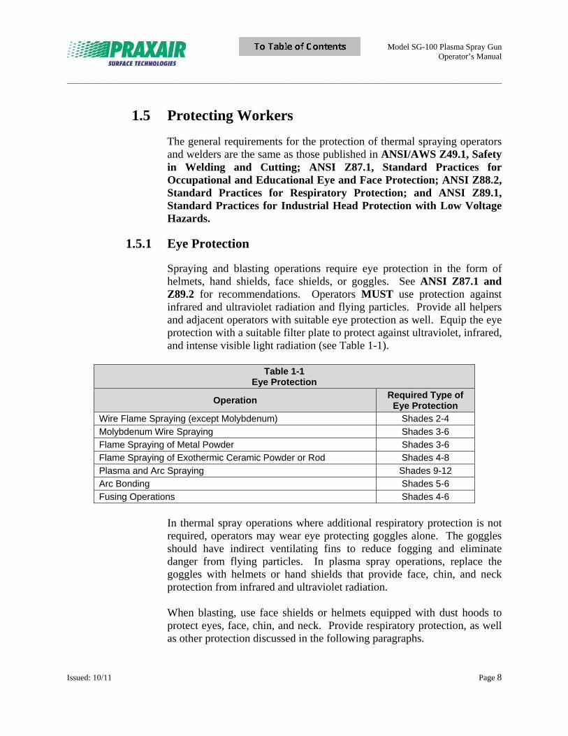
Spraying and blasting operations require eye protection in the form of helmets, hand shields, face shields, or goggles. See ANSI Z87.1 and Z89.2 for recommendations. Operators MUST use protection against infrared and ultraviolet radiation and flying particles. Provide all helpers and adjacent operators with suitable eye protection as well. Equip the eye protection with a suitable filter plate to protect against ultraviolet, infrared, and intense visible light radiation (see Table 1-1).
Table 1-1
Eye Protection
Operation Required Type of
Eye Protection Wire Flame Spraying (except Molybdenum) Shades 2-4
Molybdenum Wire Spraying Shades 3-6
Flame Spraying of Metal Powder Shades 3-6
Flame Spraying of Exothermic Ceramic Powder or Rod Shades 4-8
Plasma and Arc Spraying Shades 9-12
Arc Bonding Shades 5-6
Fusing Operations Shades 4-6
In thermal spray operations where additional respiratory protection is not required, operators may wear eye protecting goggles alone. The goggles should have indirect ventilating fins to reduce fogging and eliminate danger from flying particles. In plasma spray operations, replace the goggles with helmets or hand shields that provide face, chin, and neck protection from infrared and ultraviolet radiation. When blasting, use face shields or helmets equipped with dust hoods to protect eyes, face, chin, and neck. Provide respiratory protection, as well as other protection discussed in the following paragraphs.

Model SG-100 Plasma Spray Gun Operator’s Manual
_____________________________________________________________________________________________________________________
Issued: 10/11 Page 9
1.5.2 Respiratory Protection
Respiratory protection is necessary for most spray and blast operations. Selection of device is determined, in accordance with ANSI Z88.2, by the nature, type, and magnitude of the fume and gas involved. Select only devices approved by the U.S. Bureau of Mines, National Institute of Occupational Safety and Health (NIOSH), or an other approved authority. Suggested devices for typical thermal spraying and blasting operations include: Blasting in the open: use a mechanical filter respirator with a face shield and dust hood or a self-contained breathing apparatus. Thermal spraying in confined or semi-confined spaces: use an air line respirator. Use a device similar to the one described below for abrasive blasting. Abrasive blasting in confined or enclosed spaces: use a continuous flow air line respirator consisting of a continuous flow air line respirator, a full face piece or helmet, and dust hood sufficient to protect the head and neck from rebounding abrasive material. Minimum air flow to the respirator should be 4 CFM (113.3 L/minute) at the face piece and 6 CFM (170 L/minute) entering the helmet or hood. Fresh air blowers are preferred to compressed air as an air source of respirator air. If adequate ventilation is not provided, use an in-line vortex cooler when possible for operator comfort. Filter the air supply line to remove objectionable odors, oil or water mist (or both), and rust particles from the air. Locate the air intake to ensure the respirator receives clean, dry air (CDA). If gaseous air contaminants such as carbon monoxide are possible, use a separate air purifier. Grade D or better compressed air is considered breathable. Thermal spraying in an open or a well-ventilated work area: additional respiratory protection may not be necessary. In borderline cases, use approved mechanical filter respirators for protection against dust and metal fumes. Borderline cases are those that consist of light work or short duration with nontoxic materials, but with some dust exposure.
Continuous flow air line respirators are adequate for thermal spraying operations involving most commonly used materials. If the respirator air supply fails and the contaminant in the space is not immediately harmful to health, the operator may stop operations, remove the supply line, and return to breathable air.
Model SG-100 Plasma Spray Gun Operator’s Manual
_____________________________________________________________________________________________________________________
Issued: 10/11 Page 10
When highly toxic materials are being applied, the contaminated air is considered immediately harmful and the operator MUST NOT remove the respirator. In these applications, the respirator must be equipped with an emergency auxiliary source of breathable air that the operator can breathe while working in the confined space.
1.5.3 Noise Protection
The Occupational Safety and Health Administration (OSHA) requires employers to provide safe working conditions. OSHA also requires employees to comply with all rules, regulations and orders that apply to their actions and conduct. OSHA does not provide thermal spraying-specific rules but establishes general rules for the control of unsafe and unhealthy elements.
1.5.3.1 Noise and Noise Level
Noise is an unneeded and objectionable sound. Excess noise reduces productivity, slows reaction times, and causes tension, hearing impairment, and nervousness. Noise level is a measurement of sound wave energy (pressure). The standard unit of sound measurement is decibels (dB). See Table 1-3 for safe exposure times at different noise levels.
Thermal Spray Noise Levels
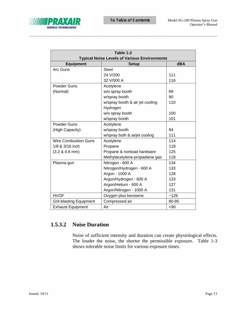
Thermal spray processes generate high noise levels. Table 1-2 shows typical noise levels of various environments. To verify whether a problem exists, measure the noise and noise levels at your site.
Model SG-100 Plasma Spray Gun Operator’s Manual
_____________________________________________________________________________________________________________________
Issued: 10/11 Page 11
Table 1-2 Typical Noise Levels of Various Environments
Equipment Setup dBA
Arc Guns Steel 24 V/200 32 V/500 A
111 116
Powder Guns (Normal)
Acetylene w/o spray booth w/spray booth w/spray booth & air jet cooling Hydrogen w/o spray booth w/spray booth
89 90 110 100 101
Powder Guns (High Capacity)
Acetylene w/spray booth w/spray both & airjet cooling
94 111
Wire Combustion Guns 1/8 & 3/16 inch (3.2 & 4.8 mm)
Acetylene Propane Propane & nonload hardware Methylacetylene-propadiene gas
114 118 125 118
Plasma gun Nitrogen - 600 A Nitrogen/Hydrogen - 600 A Argon - 1000 A Argon/Hydrogen - 600 A Argon/Helium - 600 A Argon/Nitrogen - 1000 A
134 133 128 133 127 131
HVOF Oxygen plus kerosene ~126
Grit-blasting Equipment Compressed air 80-85
Exhaust Equipment Air <90
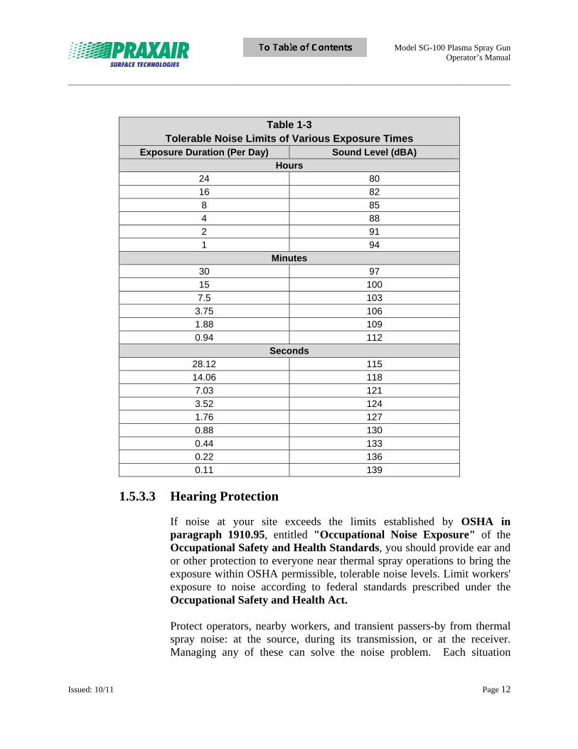
1.5.3.2 Noise Duration
Noise of sufficient intensity and duration can create physiological effects. The louder the noise, the shorter the permissible exposure. Table 1-3 shows tolerable noise limits for various exposure times.
Model SG-100 Plasma Spray Gun Operator’s Manual
_____________________________________________________________________________________________________________________
Issued: 10/11 Page 12
Table 1-3 Tolerable Noise Limits of Various Exposure Times
Exposure Duration (Per Day) Sound Level (dBA)
Hours 24 80
16 82
8 85
4 88
2 91
1 94
Minutes
30 97
15 100
7.5 103
3.75 106
1.88 109
0.94 112
Seconds
28.12 115
14.06 118
7.03 121
3.52 124
1.76 127
0.88 130
0.44 133
0.22 136
0.11 139
1.5.3.3 Hearing Protection
If noise at your site exceeds the limits established by OSHA in paragraph 1910.95, entitled "Occupational Noise Exposure" of the Occupational Safety and Health Standards, you should provide ear and or other protection to everyone near thermal spray operations to bring the exposure within OSHA permissible, tolerable noise levels. Limit workers' exposure to noise according to federal standards prescribed under the Occupational Safety and Health Act. Protect operators, nearby workers, and transient passers-by from thermal spray noise: at the source, during its transmission, or at the receiver. Managing any of these can solve the noise problem. Each situation
Model SG-100 Plasma Spray Gun Operator’s Manual
_____________________________________________________________________________________________________________________
Issued: 10/11 Page 13
contains many variables, so each case must be treated individually. This manual can provide only general suggestions for noise control. Use engineering or administrative controls to reduce noise or noise exposure. Engineering controls include: redesign equipment, relocate equipment, change operating conditions, isolate equipment acoustically, insulate work area, and provide operator hearing protection. Administrative controls include planning and scheduling to reduce exposure. If engineering and administrative controls do not achieve acceptable noise control, OSHA regulations allow use of suitable personal protective equipment. This also applies while engineering and administrative controls are being established. Mufflers on thermal spray equipment are impractical and ineffective. Simple baffles between the gun and nearby personnel are not effective because noise scatters around the baffle. Specially designed sound absorbing materials provide a 5 dB reduction to adjacent areas. Sound absorbing materials on walls and hanging baffles can reduce nearby levels but do not solve the problem for the operator.
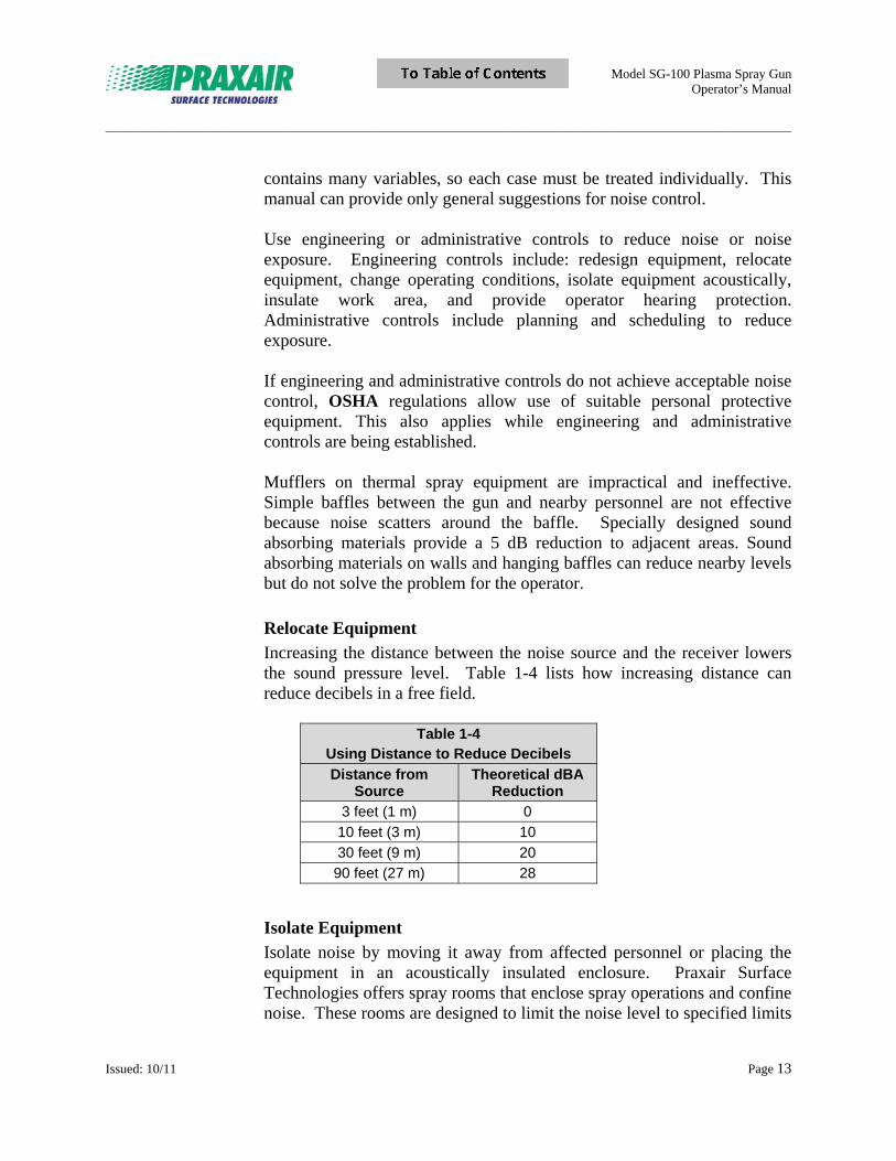
Relocate Equipment
Increasing the distance between the noise source and the receiver lowers the sound pressure level. Table 1-4 lists how increasing distance can reduce decibels in a free field.
Table 1-4
Using Distance to Reduce Decibels
Distance from Source
Theoretical dBA Reduction
3 feet (1 m) 0
10 feet (3 m) 10
30 feet (9 m) 20
90 feet (27 m) 28
Isolate Equipment
Isolate noise by moving it away from affected personnel or placing the equipment in an acoustically insulated enclosure. Praxair Surface Technologies offers spray rooms that enclose spray operations and confine noise. These rooms are designed to limit the noise level to specified limits
Model SG-100 Plasma Spray Gun Operator’s Manual
_____________________________________________________________________________________________________________________
Issued: 10/11 Page 14
outside the room. Contact Praxair Surface Technologies for additional information.
Insulate Work Area
Blocking the path of sound transmission by lining the work area with sound absorbing materials provides significant noise reduction. Consult noise control experts for material recommendations.
Plan and Schedule to Reduce Exposure Time
Engineering controls focus on eliminating, reducing, or containing the noise hazard. Administrative controls attempt to reduce exposure time. Planning and scheduling are best used where spraying is intermittent. Usually, spraying time is a small percentage of the total job compared with setup, surface preparation, and finishing. If spraying time exceeds the permissible levels for noise exposure, schedule jobs over more than one shift or day to keep exposure within maximum limits. More than one operator can spray jobs to keep the exposure of any one person within limits. Spraying outside of regular plant hours can control exposure of persons near the operation. Also, rotate personnel assignments in the vicinity of the thermal spraying operation to control exposure.
1.5.4 Protective Clothing
When working in confined spaces, wear flame resistant clothing, and leather or rubber gauntlet gloves. Clothing should fit snugly around the wrists and ankles to keep sprayed materials and dust away from the skin. For work in the open, ordinary clothing may be sufficient. However, open shirt collars and unbuttoned pocket flaps are potential hazards. Always wear high-top shoes and cuffless trousers that cover the tops of the shoes. If workers will be spraying toxic materials, consult a material supplier for information on protective clothing. Plasma spraying generates intense ultraviolet radiation that can cause a "sunburn" through normal clothing. When plasma spraying, wear clothing such as thick, tightly woven wool clothing that provides protection against radiation. Also wear appropriate eye protection. For more intense exposure, leather capes or aluminized clothing is necessary. Take care to attach aluminized clothing to the outside of the face shield so radiation is
Model SG-100 Plasma Spray Gun Operator’s Manual
_____________________________________________________________________________________________________________________
Issued: 10/11 Page 15
not reflected onto the face shield. Wear aluminized gloves and dark, fire-retardant clothing. Arc spraying radiation protection is similar to that for electric arc welding and is outlined in ANSI/AWS Z49.1. Some arc spraying guns are equipped with an arc shield that protects the operator from direct exposure to the arc. Also use a helmet if any parts of the body are exposed to direct arc radiation or if exceptionally reflective substrates are being sprayed.
1.5.5 Confined Spaces
Spaces such as a closed tank, boiler, pressure vessel, or ship compartment are considered confined spaces. Review AWS F3.2, Recommended Safe Practices for the Preparation for Welding and Cutting of Containers and Piping That Have Held Hazardous Substances, if the confined space previously held combustible materials. Work in confined spaces requires ventilation. See the standards referred to in "Compressed Gas Cylinders" in section 1.4.1 of this manual for ventilation requirements. When you are thermal spraying in any confined space, keep the gas cylinders out of the work space.
1.5.5.1 Rapid Emergency Exit
If operators must enter a confined space through a small opening, provide the means for rapid emergency exit. If operators are using safety belts and life lines for this purpose, attach them to the operator's body so they will not jam in a small exit space. Station at least one attendant trained in rescue work outside the confined space at all times and verify this person's ability to remove the operator from the confined space if an emergency should occur.
Model SG-100 Plasma Spray Gun Operator’s Manual
_____________________________________________________________________________________________________________________
Issued: 10/11 Page 16
1.5.5.2 Factors to Consider
To eliminate the chance of gas escaping through leaks or improperly closed valves, prior to entering the confined space, close the gun valve, and shut off the gas supply at a point outside the confined space. If possible, remove the gun and hose from the confined space. Evaluate oxygen level inside the confined space with oxygen monitoring equipment. The amount of contamination to which an operator is exposed during spray operations depends on many factors. Consider the following factors when selecting ventilation systems for operator safety:
Volume of space in which the operation is performed Number of spray/abrasive blast units operating in that space Sources of hazardous fumes, gases, or dusts (varies depending on
material sprayed) Heat generated by the spraying process Presence of volatile solvents
Where thermal spraying operations are incidental to general operations, apply local exhaust ventilation to the spray areas to prevent contamination of the general work area. Carefully maintain individual respiratory protective devices. Clean and disinfect devices before transferring them between employees (see ANSI Z88.2). Provide mechanical ventilation for operations not performed in the open or in a properly designed and ventilated room. Ventilation equipment usually consists of motor driven portable exhausters with flexible piping or ducts that remove dust rapidly and allows operators suitable visibility. A ventilation system does not preclude the need for respiratory protection devices. See "Respiratory Protection," section 1.5.2, for recommendations on protective devices and filtration systems. When thermal spraying on a machine tool such as a lathe, mount an exhaust hood at the end of the carriage so that it travels with the gun, exhausting dust and fumes into the dust collector. Aim the gun so the sprayed material enters the face of the hood. An average lathe hood is about 2 ft2 (0.2m2) and the velocity of air entering the opening should be at least 200 feet/minute (1 m/s). The hood opening design should eliminate turbulence along the sides that could force spray dust into the operator's
Model SG-100 Plasma Spray Gun Operator’s Manual
_____________________________________________________________________________________________________________________
Issued: 10/11 Page 17
breathing zone. In permanent installations, the entire tool is enclosed except the front; air enters the enclosure at approximately 300 feet/minute (1.5 m/s). The hood top can be hinged to facilitate loading and unloading with a crane. In automatic and production spraying, the entire mechanism is often totally enclosed. Refer to "Industrial Ventilation" published by the American Conference of Governmental Industrial Hygienists (ACGIH). Provide exhaust equipment for dry grinding or lapping operations performed on sprayed coatings. Consult OSHA Occupational Safety and Health Standard 1910.94, Ventilation. Equip spray cabinets used for spraying small and medium size parts with exhaust ventilation with an air velocity of 200 to 400 feet/minute (1 to 2 m/s) entering the hood opening. This is often referred to as the "face velocity." Operate the spray equipment within the face area of the hood and direct the spray into it. Design the cabinet to eliminate turbulent currents. Refer to "Industrial Ventilation" published by ACGIH.
Blasting Rooms
Design and maintain separate rooms for grit-blasting and thermal spraying. Design of a blasting room should include adequate lighting and a dry cartridge-type ventilation system having ventilation down draft and longitudinal air flow at a velocity of at least 80 to 100 feet/minute (0.4 to 0.5 m/s). Thoroughly investigate local, state, and federal regulations before exhausting directly into the atmosphere. A blasting room should include a dust collection system that satisfies all laws and local ordinances for the type of work being done in the room. Grit-blasting and thermal spraying will require their own independent dust collectors. Although dry cartridge-type dust collectors are suitable for use in both the grit blast and thermal spray environments, it is suggested to refer to "Industrial Ventilation", a manual of recommended practice with a compilation of research data and information on design, maintenance and evaluation of industrial exhaust ventilation systems. This manual is not intended to be used as law, but rather as a guide. In addition, the NFPA guidelines should be used for the handling of metallic and other materials. Avoid using the grit-blasting room for thermal spraying because the dust collectors can quickly become clogged with a combination of thermal spray and grit dust. Also, an accumulation of metallic dust may create a fire or an explosion hazard.
Model SG-100 Plasma Spray Gun Operator’s Manual
_____________________________________________________________________________________________________________________
Issued: 10/11 Page 18
Replace ventilation-removed air with clean, breathable air. Choose fans that provide at least 10 air changes per minute. If your site uses portable gasoline or diesel engines to drive ventilators, position them so that engine exhaust cannot be drawn into the ventilating system or the intake of the respirator air compressor. Provide operators with respiratory protection as detailed in "Respiratory Protection" in section 1.5.2. Ground all fans, pipes, dust arrestors, and motors. DO NOT ground to piping that carries fuel gas, oxygen, or other flammables or combustibles. Run ventilation fans when operators are cleaning out booths, pipes, etc. to prevent accumulation of dust or fumes in the system. NEVER weld or cut while repairing any ventilation or dust collecting equipment unless the equipment has been thoroughly cleaned.
1.6 Toxic Material
PERSONAL INJURY HAZARD:
Almost any material, in finely divided form, can damage the respiratory system. Damage is often not sensed immediately. Take care to keep floors, work benches, and booths free of dusty residues. Carefully clean protective clothing to remove dust, or discard clothing after use. Specific precautions for protecting the health of spray equipment operators vary according to the type of material being sprayed.
1.6.1 Beryllium and Lead
Praxair Surface Technologies does not recommend spraying beryllium, lead, or their compounds because they are highly toxic and hazardous.
1.6.2 Cadmium
Cadmium is highly toxic and hazardous. Use respiratory protective equipment such as fume respirators approved by the U.S. Bureau of Mines, National Institute of Occupational Safety and Health (NIOSH), or other approving authority.
Model SG-100 Plasma Spray Gun Operator’s Manual
_____________________________________________________________________________________________________________________
Issued: 10/11 Page 19
1.6.3 Cobalt, Chromium, and Tellurium
The principal hazard when spraying or blasting these materials comes from ingestion, inhalation, and the subsequent absorption of fumes, dust, or vapors. The fumes and dust from chromium alloys (such as stainless steels, nickel chromium, and chromium oxide) and tellurium are toxic and hazardous. Provide respiratory protection and adequate ventilation wherever the fume and dust concentration is above the threshold limit (see "Threshold Limit Valves" in section 1.6.6).
1.6.4 Tin and Zinc
Usually encountered in the forms of their oxides and not considered toxic, tin and zinc may cause violent illness, including coughing, headache and, particularly in the case of zinc oxide fumes, nausea, vomiting, chills, fever, muscle and joint pain, and marked thirst. (In the case of zinc oxide, the effect has been known as "brass founder's ague," "brass chills," "zinc fever," or "metal fume fever.") Temporary short term immunity can be developed. Prevention consists of adequate ventilation and proper respirators (see "Respiratory Protection" in section 1.5.2 and "Confined Spaces" in section 1.5.5). Preclude from the work any operators with pulmonary disease or those who continue to suffer discomfort even with proper ventilation and respirator measures.
1.6.5 Solvents
The radiation generated by plasma or arc spraying causes rapid decomposition of some solvent vapors into noxious and toxic gases, even at considerable distance from the arc. Slow extraction of the part from the solvent cleaning tank can reduce this problem. When spraying vapor-degreased parts, take extra care to see that all solvent (vapors or liquid films or drops of solvent caught by pockets and crevices) is removed prior to thermal spraying. The ultraviolet radiation from plasma and arc spraying generates airborne ozone. The amount of ozone produced may exceed the maximum allowable concentration in confined spaces. Excess ozone production should be avoided.
Model SG-100 Plasma Spray Gun Operator’s Manual
_____________________________________________________________________________________________________________________
Issued: 10/11 Page 20
1.6.6 Threshold Limit Values
Threshold Limit Values (TLV) are air concentration levels of hazardous materials for exposures not exceeding a total of eight hours daily. TLVs are published annually by the ACGIH. Consult a current TLV list concerning the maximum allowable concentration of toxic material allowed. Conduct air sampling to determine the ventilation requirements for operations involving the previously listed materials. When less toxic metals are sprayed, the concentration of dust or fumes in the work area must not exceed the TLV for eight-hour exposure. Provide respiratory protection devices and exhaust ventilation when the dust or fume concentration is sufficiently high to cause operator discomfort even when the appropriate TLV is not exceeded.
1.7 Safety Standards
In addition to the contents of this chapter, a variety of industry publications contain safety standards. See the related publications list on page vii.
Model SG-100 Plasma Spray Gun Operator’s Manual
_____________________________________________________________________________________________________________________
Issued: 12/11 Page 21
Section 2 Equipment Description
2.1 Plasma Spray Process Description
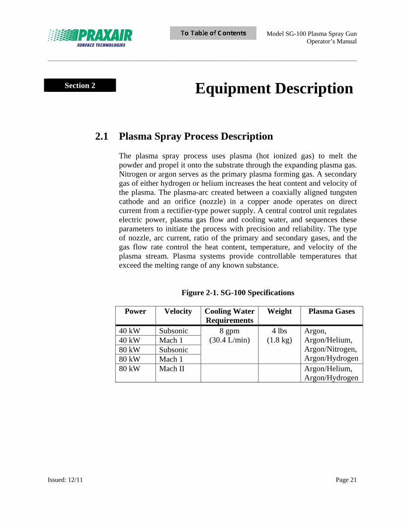
The plasma spray process uses plasma (hot ionized gas) to melt the powder and propel it onto the substrate through the expanding plasma gas. Nitrogen or argon serves as the primary plasma forming gas. A secondary gas of either hydrogen or helium increases the heat content and velocity of the plasma. The plasma-arc created between a coaxially aligned tungsten cathode and an orifice (nozzle) in a copper anode operates on direct current from a rectifier-type power supply. A central control unit regulates electric power, plasma gas flow and cooling water, and sequences these parameters to initiate the process with precision and reliability. The type of nozzle, arc current, ratio of the primary and secondary gases, and the gas flow rate control the heat content, temperature, and velocity of the plasma stream. Plasma systems provide controllable temperatures that exceed the melting range of any known substance.
Figure 2-1. SG-100 Specifications
Power Velocity Cooling Water Requirements
Weight Plasma Gases
40 kW Subsonic 8 gpm (30.4 L/min)
4 lbs (1.8 kg)
Argon, Argon/Helium, Argon/Nitrogen,Argon/Hydrogen
40 kW Mach 1 80 kW Subsonic 80 kW Mach 1 80 kW Mach II Argon/Helium,
Argon/Hydrogen
Model SG-100 Plasma Spray Gun Operator’s Manual
_____________________________________________________________________________________________________________________
Issued: 12/11 Page 22
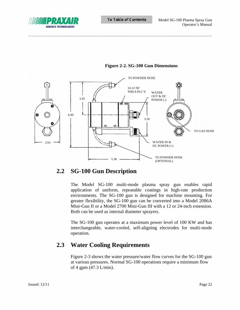
Figure 2-2. SG-100 Gun Dimensions
2.2 SG-100 Gun Description
The Model SG-100 multi-mode plasma spray gun enables rapid application of uniform, repeatable coatings in high-rate production environments. The SG-100 gun is designed for machine mounting. For greater flexibility, the SG-100 gun can be converted into a Model 2086A Mini-Gun II or a Model 2700 Mini-Gun III with a 12 or 24-inch extension. Both can be used as internal diameter sprayers.
The SG-100 gun operates at a maximum power level of 100 KW and has interchangeable, water-cooled, self-aligning electrodes for multi-mode operation.
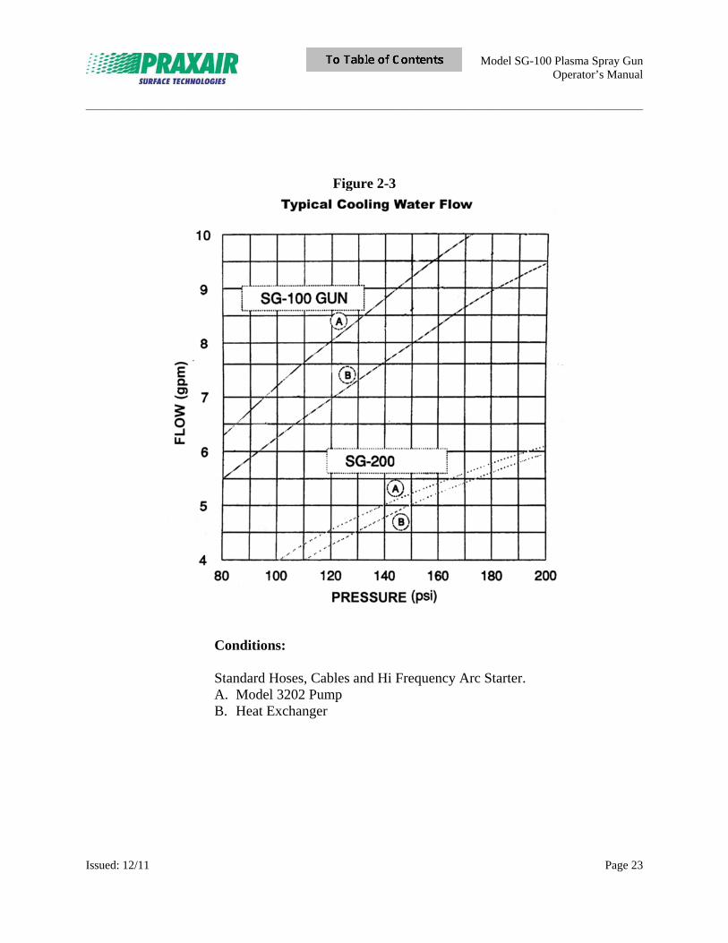
2.3 Water Cooling Requirements
Figure 2-3 shows the water pressure/water flow curves for the SG-100 gun at various pressures. Normal SG-100 operations require a minimum flow of 4 gpm (47.3 L/min).
6.90
3.45
3.50
2.63
5.38
WATER IN & DC POWER (+)
TO POWDER HOSE (OPTIONAL)
TO GAS HOSE
WATER OUT & DC POWER (-)
TO POWDER HOSE
10-32 NF THD 8 PLC’S
Model SG-100 Plasma Spray Gun Operator’s Manual
_____________________________________________________________________________________________________________________
Issued: 12/11 Page 23
Figure 2-3
Conditions: Standard Hoses, Cables and Hi Frequency Arc Starter.
A. Model 3202 Pump B. Heat Exchanger
Model SG-100 Plasma Spray Gun Operator’s Manual
_____________________________________________________________________________________________________________________
Issued: 12/11 Page 24
2.4 Optional Items The following items are each sold separately.
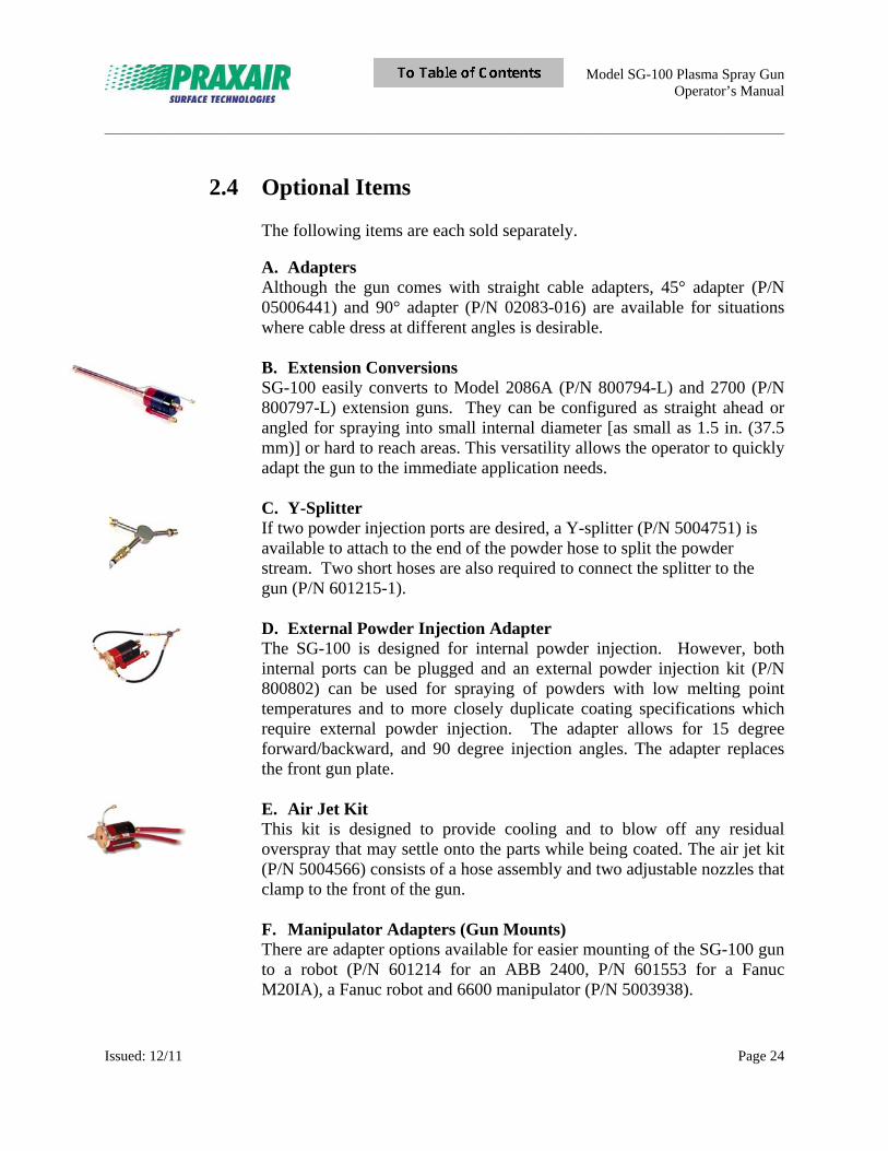
A. Adapters Although the gun comes with straight cable adapters, 45° adapter (P/N 05006441) and 90° adapter (P/N 02083-016) are available for situations where cable dress at different angles is desirable. B. Extension Conversions SG-100 easily converts to Model 2086A (P/N 800794-L) and 2700 (P/N 800797-L) extension guns. They can be configured as straight ahead or angled for spraying into small internal diameter [as small as 1.5 in. (37.5 mm)] or hard to reach areas. This versatility allows the operator to quickly adapt the gun to the immediate application needs. C. Y-Splitter If two powder injection ports are desired, a Y-splitter (P/N 5004751) is available to attach to the end of the powder hose to split the powder stream. Two short hoses are also required to connect the splitter to the gun (P/N 601215-1). D. External Powder Injection Adapter The SG-100 is designed for internal powder injection. However, both internal ports can be plugged and an external powder injection kit (P/N 800802) can be used for spraying of powders with low melting point temperatures and to more closely duplicate coating specifications which require external powder injection. The adapter allows for 15 degree forward/backward, and 90 degree injection angles. The adapter replaces the front gun plate. E. Air Jet Kit This kit is designed to provide cooling and to blow off any residual overspray that may settle onto the parts while being coated. The air jet kit (P/N 5004566) consists of a hose assembly and two adjustable nozzles that clamp to the front of the gun. F. Manipulator Adapters (Gun Mounts) There are adapter options available for easier mounting of the SG-100 gun to a robot (P/N 601214 for an ABB 2400, P/N 601553 for a Fanuc M20IA), a Fanuc robot and 6600 manipulator (P/N 5003938).
Model SG-100 Plasma Spray Gun Operator’s Manual
_____________________________________________________________________________________________________________________
Issued: 12/11 Page 25
Section 3 Installation
3.1 Receiving-Handling Before installing this equipment, clean all packing material from around the unit and carefully inspect for any damage that may have occurred during shipment. Any claim for loss or damage that may have occurred in transit must be filed by the purchaser with the carrier. A copy of the bill of lading will be furnished by the manufacturer on request if occasion to file a claim arises.
3.2 SG-100 Gun Installation
The SG-100 gun must be installed onto a secure structure such as a robot arm, X-Y manipulator, or lathe, using one of the available optional brackets.
WARNING: ELECTRIC SHOCK can kill. Do not touch live electrical parts. The gun is electrically “live” while the power source is ON (approx. 32 VDC). Never touch the plasma gun while it is in operation.
Shut down unit and disconnect input power and employ “lockout/tagging procedures” on power source before making any connections to the gun. Lockout/tagging procedures consist of padlocking line disconnect switch in open position, removing fuses from fuse box, or shutting off and red-tagging circuit breaker or other disconnecting device.
ELECTRICALLY ISOLATE SG-100 gun when gun is to be machine mounted. Only use non-conductive brackets supplied by the manufacturer for machine mounting of SG-100 gun.
Model SG-100 Plasma Spray Gun Operator’s Manual
_____________________________________________________________________________________________________________________
Issued: 12/11 Page 26
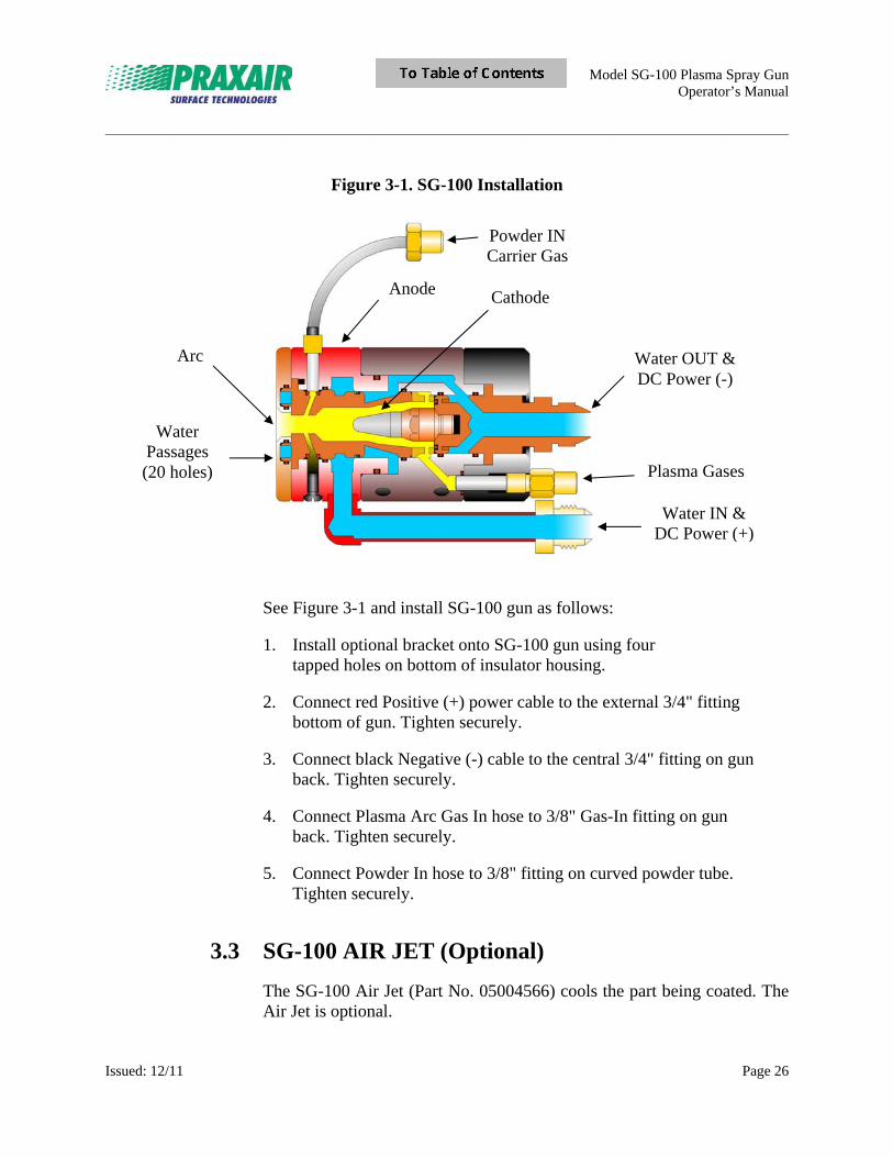
Figure 3-1. SG-100 Installation
See Figure 3-1 and install SG-100 gun as follows: 1. Install optional bracket onto SG-100 gun using four tapped holes on bottom of insulator housing.
2. Connect red Positive (+) power cable to the external 3/4" fitting bottom of gun. Tighten securely.
3. Connect black Negative (-) cable to the central 3/4" fitting on gun back. Tighten securely.
4. Connect Plasma Arc Gas In hose to 3/8" Gas-In fitting on gun back. Tighten securely.
5. Connect Powder In hose to 3/8" fitting on curved powder tube. Tighten securely.
3.3 SG-100 AIR JET (Optional)
The SG-100 Air Jet (Part No. 05004566) cools the part being coated. The Air Jet is optional.
Water Passages (20 holes)
Arc
Anode
Powder IN Carrier Gas
Cathode
Water OUT & DC Power (-)
Plasma Gases
Water IN & DC Power (+)
Model SG-100 Plasma Spray Gun Operator’s Manual
_____________________________________________________________________________________________________________________
Issued: 12/11 Page 27
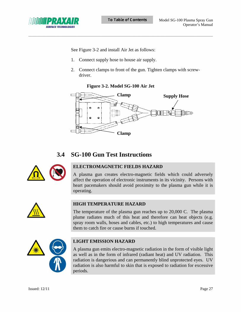
See Figure 3-2 and install Air Jet as follows: 1. Connect supply hose to house air supply.
2. Connect clamps to front of the gun. Tighten clamps with screw- driver.
Figure 3-2. Model SG-100 Air Jet
3.4 SG-100 Gun Test Instructions
ELECTROMAGNETIC FIELDS HAZARD
A plasma gun creates electro-magnetic fields which could adversely affect the operation of electronic instruments in its vicinity. Persons with heart pacemakers should avoid proximity to the plasma gun while it is operating.
HIGH TEMPERATURE HAZARD
The temperature of the plasma gun reaches up to 20,000 C. The plasma plume radiates much of this heat and therefore can heat objects (e.g. spray room walls, hoses and cables, etc.) to high temperatures and cause them to catch fire or cause burns if touched.
LIGHT EMISSION HAZARD
A plasma gun emits electro-magnetic radiation in the form of visible light as well as in the form of infrared (radiant heat) and UV radiation. This radiation is dangerious and can permanently blind unprotected eyes. UV radiation is also harmful to skin that is exposed to radiation for excessive periods.
Clamp Supply Hose
Clamp
Model SG-100 Plasma Spray Gun Operator’s Manual
_____________________________________________________________________________________________________________________
Issued: 12/11 Page 28
Wear hearing protection.
Operation of a plasma gun generates strong noise emissions (> 130 dBa), which can cause damage or loss of hearing.
3.4.1 Setup and pretest:
3.4.1.1 Mount the gun. 3.4.1.2 Connect the positive and negative water cooled cables to
the gun, making sure that they are connected to the correct fittings of the gun in the proper polarity.
3.4.1.3 Connect the arc gas (argon) hose to the arc gas fitting at
the back of the gun, taking care to not over tighten the fitting as this will cause the back insulator to crack.
3.4.1.4 Turn on the cooling water system and set the water flow
to give a minimum of 6 gpm (22.7 L/min). 3.4.1.5 Initiate the arc gas flow and set the regulator to give 60
psi (120 SCFH) [4.1 bar (56.6 L/min)].
3.4.1.6 Check for water leaks. Do not continue if leaks are present.
3.4.2 Unit Test:
3.4.2.1 Energize the power supply.
3.4.2.2 Set for 700 amps/ max 750 amps.
3.4.2.3 Start the arc and inspect the plume to see if it is fluttering or off center.
3.4.2.4 Allow the gun to run for 10 minutes.
3.4.2.5 Check that the amps are stable and that the system volts are 30 V +/- 2 V, gun volts are 24 V +/- 2 V.
3.4.2.6 Press the arc start button again just before shutting off the gun; this helps eliminate the hard starting of a new anode on the second start.
Re-start the gun twice more to check for ease of starting.

Model SG-100 Plasma Spray Gun Operator’s Manual
_____________________________________________________________________________________________________________________
Issued: 12/11 Page 29
Section 4 Operation
WARNING: ELECTRIC SHOCK can kill. Do not touch live electrical parts. The gun is electrically “live” while power source is ON (approx. 32 VDC).
Shut down unit and disconnect input power and employ “lockout/tagging procedures” on power source before making any connections to the gun. Lockout/tagging procedures consist of padlocking line disconnect switch in open position, removing fuses from fuse box, or shutting off and red-tagging circuit breaker or other disconnecting device.
ELECTRICALLY ISOLATE SG-100 gun when gun is to be machine mounted. Only use non-conductive brackets supplied by the manufacturer for machine mounting of SG-100 gun.
ELECTROMAGNETIC FIELDS HAZARD
A plasma gun creates electro-magnetic fields which could adversely affect the operation of electronic instruments in its vicinity. Persons with heart pacemakers should avoid proximity to the plasma gun while it is operating.
HIGH TEMPERATURE HAZARD
The temperature of the plasma gun reaches up to 20,000° C. The plasma plume radiates much of this heat and therefore can heat objects (e.g. spray room walls, hoses and cables, etc.) to high temperatures and cause them to catch fire or cause burns if touched.
LIGHT EMISSION HAZARD
A plasma gun emits electro-magnetic radiation in the form of visible light as well as in the form of infrared (radiant heat) and UV radiation. This radiation is dangerous and can permanently blind unprotected eyes. UV radiation is also harmful to skin that is exposed to radiation for excessive periods.
Model SG-100 Plasma Spray Gun Operator’s Manual
_____________________________________________________________________________________________________________________
Issued: 12/11 Page 30
Wear hearing protection.
Operation of a plasma gun generates strong noise emissions (> 130 dBa), which can cause damage or loss of hearing.
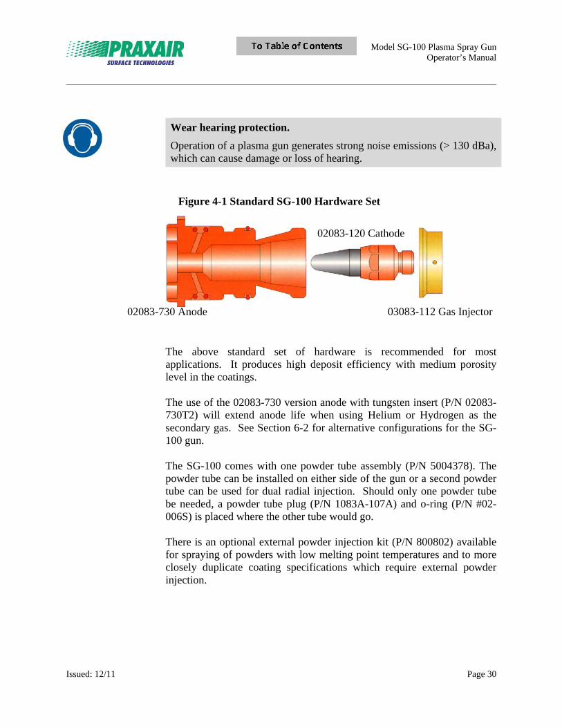
Figure 4-1 Standard SG-100 Hardware Set
The above standard set of hardware is recommended for most applications. It produces high deposit efficiency with medium porosity level in the coatings. The use of the 02083-730 version anode with tungsten insert (P/N 02083-730T2) will extend anode life when using Helium or Hydrogen as the secondary gas. See Section 6-2 for alternative configurations for the SG-100 gun.
The SG-100 comes with one powder tube assembly (P/N 5004378). The powder tube can be installed on either side of the gun or a second powder tube can be used for dual radial injection. Should only one powder tube be needed, a powder tube plug (P/N 1083A-107A) and o-ring (P/N #02-006S) is placed where the other tube would go. There is an optional external powder injection kit (P/N 800802) available for spraying of powders with low melting point temperatures and to more closely duplicate coating specifications which require external powder injection.
02083-730 Anode 03083-112 Gas Injector
02083-120 Cathode
Model SG-100 Plasma Spray Gun Operator’s Manual
_____________________________________________________________________________________________________________________
Issued: 12/11 Page 31
4.1 Plasma Spray Shop Notes Factors that contribute to a quality plasma sprayed coating include equipment choice, powder quality, surface preparation, gun operating parameters, powder feed rates, part and gun manipulation, part cooling, and overspray cleaning. Disregarding any of these factors causes poor coating quality.
A. Choice of Proper Electrodes
Several operating regimes and powder injection schemes are necessary to spray the variety of materials used for plasma spraying. This is because of the variations in their physical and thermal properties. The relative gas velocity for Praxair Surface Technologies’ (PST) plasma guns is given in terms of subsonic, MACH I, and MACH II. Gas velocity dictates powder particle velocity. PST guns are made in configurations for spraying both external and internal surfaces. Additionally, internal and external powder injection points are available, with a range of injection angles, to accommodate the melting characteristics and particle sizes of the range of powders to be sprayed. This flexibility enables proper heating of the powder preventing the deposition of unmelted powder or the vaporization of fine particulate. Each coating material requires a different electrode set to obtain the desired coating characteristics, e.g., density or adhesion.
B. Powder Sprayability Most powders that have a definite melting point and a liquid phase can be plasma sprayed. Some powders may require special processing. For example, zirconium oxide powders must be partially stabilized to control the phase changes during heating and cooling. Hydrides of reactive metals are sometimes used to overcome oxidation problems. Particle size (mesh size), distribution (mesh range), and tolerances must be considered from both sprayability and economic standpoints. Powders larger than 150 mesh are not normally recommended for plasma spraying. Normally, coarser powders yield thicker coatings with lower residual stress (higher bond strength). Finer powders produce coatings that are smoother in the as-sprayed condition and have a finer microstructural texture. However, residual stress is higher with finer powder, which limits thickness buildup and decreases measured bond strength. Good cuts of powder, whether coarse or fine, will produce dense coatings.
Model SG-100 Plasma Spray Gun Operator’s Manual
_____________________________________________________________________________________________________________________
Issued: 12/11 Page 32
Powder that is too widely distributed (too many particles above and below the specified range) reduces deposit efficiency, produces poor quality coatings, and negatively affects gun operation. PST considered these factors when setting up specifications for use of this equipment with PST Powders.
C. Surface Preparation One of the most important requirements for producing a quality plasma sprayed coating is surface preparation. Usually the surface must be clean and rough.
C-1. Surface Cleanliness Before grit blasting, vapor degreasing, ultrasonic cleaning, etc. of the part is recommended. Clean the surface again after grit blasting by blowing with clean, dry gas or air and/or by rinsing with alcohol, acetone, or other solvents that do not leave a residue.
C-2. Grit Blasting Grit blasting is the most common method of surface roughening for preparation of surfaces to be coated. A surface roughness range of 125 to 400 RMS is recommended. The appropriate roughness is determined primarily by substrate and coating thicknesses. Roughness needs to be accomplished without distortion of the part to be coated. Aluminum oxide grit in the mesh ranges of -10+30, -14+40, and -30+80 are common in thermal spray. If the part to be coated is thin and could distort, reduce the blasting pressure and/or use a smaller grit size.
Replace the blasting medium when it becomes dull, fractured, or contaminated.
Coat grit blasted parts as soon as possible after grit blasting to prevent oxidation or recontamination of the part. Most steels should be coated within two hours to four hours. Coat reactive materials such as aluminum and titanium immediately after roughening and cleaning.
Since coating bond strength is closely related to surface cleanliness, the grit blast equipment used for plasma spray preparation should not be used for cleaning operations. The grit blasting operation is a roughening operation, not a cleaning operation.
Model SG-100 Plasma Spray Gun Operator’s Manual
_____________________________________________________________________________________________________________________
Issued: 12/11 Page 33
Make sure the air supplied to the grit blast equipment is clean, oil-free, and dry.
C-3. Masking Sometimes the plasma sprayed coating must be confined to a specific area of the substrate. This requires masking of some type, for both grit blasting and spraying.
Metal or silicone rubber tooling is best suited for production applications. Tooling fabrication costs are justified by the elimination of the hand masking operation. Use graphite, marking ink, or other parting compounds on the tooling to decrease clean up time and extend life.
Avoid welding anti-spatter or anti-stick compounds that may run or char when heated.
Electrical glass tape has proven successful in many applications where lower coating and substrate temperatures can be maintained. Teflon-impregnated glass tape has proven successful in applications with higher substrate temperatures. In either case, tapes using silicone mastic are less prone to degradation during spraying. Both tooling and a resilient tape have proven satisfactory for masking purposes for grit blasting and spraying operations.
D. Arc Gas Recommendations
Argon is recommended as the primary arc gas because:
1. Argon is an inert gas. It does not react with the powder or substrate. Argon also tends to provide an inert cover for the deposit.
2. Arc temperatures are extremely high, approximately 35,000°F, but the heat content of an argon plasma stream or plume is low, relative to those of the molecular or diatomic gases, e.g., nitrogen. This means the argon plasma transfers much less heat to the substrate than do other gas plasmas, thus enhancing substrate cooling.
3. Unlike nitrogen, argon forms no dangerous compounds.
Model SG-100 Plasma Spray Gun Operator’s Manual
_____________________________________________________________________________________________________________________
Issued: 12/11 Page 34
Some circumstances may call for adding small percentages of either helium or other secondary gases to the arc gas. If the plasma is not hot enough to completely melt the powder, a small percentage of secondary gas is added to the primary arc gas. Adding these gases creates entirely different operating characteristics.
E. Proper Operating Parameters
Various materials require different operating conditions, depending on thermal properties (melting temperatures, specific heat, thermal conductivity, etc.) specific gravity, and particle size and distribution. The primary objective is to have the powder particles reach an optimum temperature and velocity at the time of impact on the substrate.
The temperature of the powder particle at the time of impact with the substrate is governed primarily by the net energy of the plasma stream and the total gas flow through the plasma gun. Gas flow determines velocity, which in turn determines particle dwell time (time the particle is resident in the plasma stream). Powder particle velocity at the time of impact is governed primarily by total plasma gas flow, and particle size and density.
The plasma gun is primarily an electrical device. Increasing electrical power input normally results in an increase in net energy or enthalpy (energy in the plasma stream). Usually, an increase in electrical power input is indicated when the powder particles are not sufficiently melted before impinging on the substrate. However, circumstances may exist where the same effect can be accomplished by reducing total arc gas flow while increasing the current input. Reduced total arc gas flow decreases gas velocity thus lengthening the particle dwell time. If the particles are overheated to the point of vaporization, decrease the electrical power input, or in some cases, increase the total arc gas flow.
If using a material for which there are no operating parameters, begin with parameters for a comparable powder for which settings are available. Select a powder that has similar thermal characteristics, specific gravity and powder sizing.
Model SG-100 Plasma Spray Gun Operator’s Manual
_____________________________________________________________________________________________________________________
Issued: 12/11 Page 35
F. Powder Injection An important aspect of the plasma spray operation is obtaining maximum heat transfer efficiency from the plasma to the powder particles. There is a pronounced temperature gradient along the length and across the width of the plasma, so powder particles should be entrained in the core of the plasma, not in the cooler outer regions. Insufficient powder carrier gas flow will not push the powder up into the core, and too much carrier gas will push the powder through the core. Either too much or too little powder carrier gas results in an inferior deposit, because of insufficient heating or overheating of the powder particles. Improper carrier gas settings can also cause powder “spitting” from the gun face.
PST plasma systems currently use variable speed powder wheel feeders, which have proven to be exceptionally consistent feeding mechanisms for a wide range of particle sizes.
The optimum powder feed condition is reached when most of the powder injected into the plasma stream is carried along its axis.
G. Powder Pulsing
Pulsing is defined as inconsistent powder feed into the spray process and is usually observed as surging in the spray stream. Pulsing affects application consistency and reduces application efficiency and effectiveness.
The various known causes for pulsing, and their remedies, are:
G-1. Hose Dress Make sure the powder hose to the gun is as short as is practical and free of loops. If possible, the hose should have a downward drape toward the gun to prevent pockets of powder from forming in the hose.
G-2. Gas Leaks Gas leaks in the feeder or the powder hose, from the point of control within the console to the powder tube, can cause pulsing. Periodically check for leaks and inspect gas fittings and o-rings as part of a preventative maintenance program.
G-3. Feeder Main Bearing When deteriorated, the double row ball bearing (Part No. 012010) (in the 1264 Powder Feeder) can cause pulsing, particularly when used with the old style electric motor shaft joint coupling). Replace stiff or dirty bearings.
Model SG-100 Plasma Spray Gun Operator’s Manual
_____________________________________________________________________________________________________________________
Issued: 12/11 Page 36
G-4. Shaft Coupling In some instances, certain combinations of powder characteristics and wheel speed can cause harmonic oscillations of 1264 old style electric motor shaft coupling (P/N 015117), producing pulsation. Replace coupling with the new style flexible universal joint (P/N 01270-514).
WARNING: ELECTRIC SHOCK can kill. Do NOT connect copper wire to gun. Do NOT allow copper wire to touch the gun.
G-5. Static Static causes powder to cling to the walls of the powder hose. When sufficient powder buildup occurs, powder breaks loose and causes pulsing.
Static buildup becomes more of a problem as humidity falls. Winter is typically the worst season for static. Nonconductive materials such as ceramics and polymers aggravate the problem.
Powder hose Part No. 0985-4-12AS can help prevent static. Or, loosely spiral wrap a small, bare copper wire around the hose from the hopper-to-hose connection to a point two inches behind the gun. The copper wire drains the static charge. Take great care that the copper wire does not touch the gun as this prevents the high frequency arc starter from feeding back to the feeder circuit board.
G-6. Powder Tube Replacing the straight powder tube (Part No. 01083B-210) with the curved powder tube (Part No. 05004378) relieves pulsing problems associated with hose dress. (Operators occasionally pull the powder hose back too tightly, kinking the hose at the fitting and partially blocking flow.)
When using straight powder tubes, allow feed hose to form a natural bend at the tube to prevent internal diameter tube distortion. Internal diameter tube distortion impedes flow. PST developed curved feed tubes to alleviate this problem.
Model SG-100 Plasma Spray Gun Operator’s Manual
_____________________________________________________________________________________________________________________
Issued: 12/11 Page 37
G-7. Powder Tube O-ring When worn or damaged, the o-ring in the anode powder port can upset the powder stream and cause pulsing. Pulsing may also result if the o-ring is left out during gun assembly.
Check o-rings regularly and replace when necessary. Do not apply o-ring lube on powder tube o-ring.
G-8. Carrier Gas Flow Insufficient carrier gas flow can cause powder to accumulate in the powder hose. When build-up is sufficient a surge occurs as the powder breaks loose.
G-9. Tamper Assembly Using the tamper assembly with free flowing powders can cause over-packing of the feed wheel resulting in pulsing. G-10. Wet Powder Improperly stored powder can absorb moisture, resulting in erratic feeding and, in worst cases, severe pulsing.
Store powders properly, preferably in an oven, and use the hopper heater blanket to help prevent wet powder problems. Typical blanket temperatures are lower than 125° F (52° C).
G-11. Improperly Sized Powder Thermal spraying powder should be monomodal (normally distributed) and narrowly distributed. Powders that do not exhibit a normal distribution (having only one bump in the curve, i.e., bimodal distributions) cause pulsing and coating problems.
G-12. O-ring Lube Over application of o-ring lube in hopper metering components may contaminate and obstruct the powder feed path. Do not lubricate hopper components that make contact with the powder.
G-13. System Time Constants Pulsing can occur when the time constants approach equality throughout the spray system. Hose length and powder velocity in the powder feed hose create one time constant: the time required for powder to leave the feeder and reach the gun. A shorter time constant is found in that portion of the hose in motion at the gun end.
Model SG-100 Plasma Spray Gun Operator’s Manual
_____________________________________________________________________________________________________________________
Issued: 12/11 Page 38
One time constant interaction relates to gun motion. For example, assume the gun’s linear motion is one second left to right. Assume also, that powder traverses the hose’s moving portion in one second. In this scenario, the gun motion can overcome the powder’s velocity in the hose, resulting in slowed powder flow or pulsing. The solution lies in changing the parameters which affect the time constants:
• Adjust the carrier gas flow, optimizing the spray pattern and deposit efficiency.
• Change gun manipulation parameters (velocity), if possible.
• Change the powder hose length, or alter the free length at the gun end, to change the time constant.
• Change the powder feed hose’s internal diameter (usually smaller) to significantly alter the time constant. Decreasing the I.D. from 3/16" (4.8 mm) to 1/8" (3.2 mm) halves the time constant.
H. Traverse Speed/Pitch
Generally, a traverse speed of about 1200 in./min. (0.5 m/sec) is a good rule-of-thumb. Proper traverse speed creates deposits of approximately .001 in. (25.4 µm)/pass for metallic and coarse materials and .0005 in. (127 µm)/pass for ceramic and fine materials. Following these guidelines decreases residual stress (hence bond strength is increased), increases thickness buildup, and decreases porosity. Adjust traverse to obtain an appropriate thickness buildup rate in terms of mils/pass.
Pitch or increment is the step or feed of the gun motion associated with traverse. Generally, pitch is 0.125 - 0.200 in. (3.2 - 5.0 mm)/revolution or step. Pitch is adjusted to prevent striping or “barber poling.”
I. Substrate Cooling
Cooling jets should be used to provide a stream of gas or dry air at or near the point of impingement of the powder stream on the substrate. Cooling air cools the substrate and blows away the unmolten particles and smoke (overspray). The type of cooling gas used depends on the powder being sprayed. Argon or nitrogen can be used for most materials that oxidize readily. With materials such as titanium, which forms a nitride easily, argon is the better choice. Carbon dioxide can also be used for cooling. Dry air may be used if oxides are not a concern.
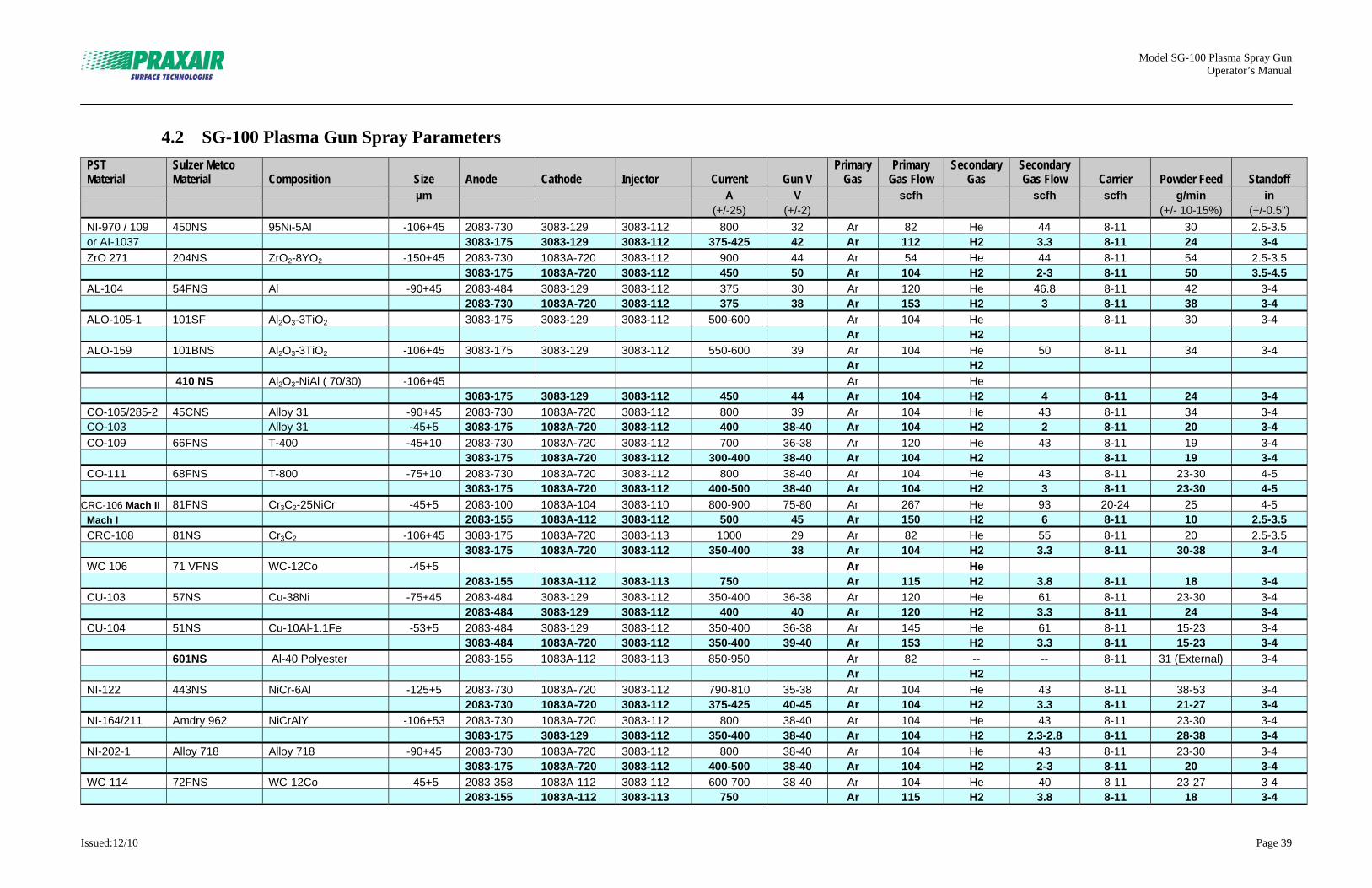
Model SG-100 Plasma Spray Gun Operator’s Manual
Issued:12/10 Page 39
4.2 SG-100 Plasma Gun Spray Parameters
PST Material
Sulzer Metco Material Composition Size Anode Cathode Injector Current Gun V
Primary Gas
Primary Gas Flow
Secondary Gas
Secondary Gas Flow Carrier Powder Feed Standoff
µm A V scfh scfh scfh g/min in (+/-25) (+/-2) (+/- 10-15%) (+/-0.5")
NI-970 / 109 450NS 95Ni-5Al -106+45 2083-730 3083-129 3083-112 800 32 Ar 82 He 44 8-11 30 2.5-3.5 or AI-1037 3083-175 3083-129 3083-112 375-425 42 Ar 112 H2 3.3 8-11 24 3-4
ZrO 271 204NS ZrO2-8YO2 -150+45 2083-730 1083A-720 3083-112 900 44 Ar 54 He 44 8-11 54 2.5-3.5 3083-175 1083A-720 3083-112 450 50 Ar 104 H2 2-3 8-11 50 3.5-4.5
AL-104 54FNS Al -90+45 2083-484 3083-129 3083-112 375 30 Ar 120 He 46.8 8-11 42 3-4 2083-730 1083A-720 3083-112 375 38 Ar 153 H2 3 8-11 38 3-4
ALO-105-1 101SF Al2O3-3TiO2 3083-175 3083-129 3083-112 500-600 Ar 104 He 8-11 30 3-4 Ar H2
ALO-159 101BNS Al2O3-3TiO2 -106+45 3083-175 3083-129 3083-112 550-600 39 Ar 104 He 50 8-11 34 3-4 Ar H2
410 NS Al2O3-NiAl ( 70/30) -106+45 Ar He 3083-175 3083-129 3083-112 450 44 Ar 104 H2 4 8-11 24 3-4
CO-105/285-2 45CNS Alloy 31 -90+45 2083-730 1083A-720 3083-112 800 39 Ar 104 He 43 8-11 34 3-4 CO-103 Alloy 31 -45+5 3083-175 1083A-720 3083-112 400 38-40 Ar 104 H2 2 8-11 20 3-4
CO-109 66FNS T-400 -45+10 2083-730 1083A-720 3083-112 700 36-38 Ar 120 He 43 8-11 19 3-4 3083-175 1083A-720 3083-112 300-400 38-40 Ar 104 H2 8-11 19 3-4
CO-111 68FNS T-800 -75+10 2083-730 1083A-720 3083-112 800 38-40 Ar 104 He 43 8-11 23-30 4-5 3083-175 1083A-720 3083-112 400-500 38-40 Ar 104 H2 3 8-11 23-30 4-5
CRC-106 Mach II 81FNS Cr3C2-25NiCr -45+5 2083-100 1083A-104 3083-110 800-900 75-80 Ar 267 He 93 20-24 25 4-5 Mach I 2083-155 1083A-112 3083-112 500 45 Ar 150 H2 6 8-11 10 2.5-3.5
CRC-108 81NS Cr3C2 -106+45 3083-175 1083A-720 3083-113 1000 29 Ar 82 He 55 8-11 20 2.5-3.5 3083-175 1083A-720 3083-112 350-400 38 Ar 104 H2 3.3 8-11 30-38 3-4
WC 106 71 VFNS WC-12Co -45+5 Ar He 2083-155 1083A-112 3083-113 750 Ar 115 H2 3.8 8-11 18 3-4
CU-103 57NS Cu-38Ni -75+45 2083-484 3083-129 3083-112 350-400 36-38 Ar 120 He 61 8-11 23-30 3-4 2083-484 3083-129 3083-112 400 40 Ar 120 H2 3.3 8-11 24 3-4
CU-104 51NS Cu-10Al-1.1Fe -53+5 2083-484 3083-129 3083-112 350-400 36-38 Ar 145 He 61 8-11 15-23 3-4 3083-484 1083A-720 3083-112 350-400 39-40 Ar 153 H2 3.3 8-11 15-23 3-4
601NS Al-40 Polyester 2083-155 1083A-112 3083-113 850-950 Ar 82 -- -- 8-11 31 (External) 3-4 Ar H2
NI-122 443NS NiCr-6Al -125+5 2083-730 1083A-720 3083-112 790-810 35-38 Ar 104 He 43 8-11 38-53 3-4 2083-730 1083A-720 3083-112 375-425 40-45 Ar 104 H2 3.3 8-11 21-27 3-4
NI-164/211 Amdry 962 NiCrAlY -106+53 2083-730 1083A-720 3083-112 800 38-40 Ar 104 He 43 8-11 23-30 3-4 3083-175 3083-129 3083-112 350-400 38-40 Ar 104 H2 2.3-2.8 8-11 28-38 3-4
NI-202-1 Alloy 718 Alloy 718 -90+45 2083-730 1083A-720 3083-112 800 38-40 Ar 104 He 43 8-11 23-30 3-4 3083-175 1083A-720 3083-112 400-500 38-40 Ar 104 H2 2-3 8-11 20 3-4
WC-114 72FNS WC-12Co -45+5 2083-358 1083A-112 3083-112 600-700 38-40 Ar 104 He 40 8-11 23-27 3-4 2083-155 1083A-112 3083-113 750 Ar 115 H2 3.8 8-11 18 3-4

Model SG-100 Plasma Spray Gun Operator’s Manual
Issued:12/10 Page 40
Notes
Model SG-100 Plasma Spray Gun Operator’s Manual
_____________________________________________________________________________________________________________________
Issued: 12/11 Page 41
Section 5 Maintenance
Inspect labels on this unit every six months for legibility. Maintain all precautionary labels in a clearly readable state and replace when necessary. See parts list for label part numbers.
5.1 Plasma-arc Starting Problems
There are several possible causes throughout a plasma system that could cause plasma-arc starting problems. To help prevent these problems, inspect and clean anodes, cathodes, housings, and other metallic components, when maintenance is performed on guns. Mineral deposits and corrosion from poor quality water can inhibit arc starting. Oxidation of the electrodes (anodes and cathodes), which is usually the result of gas supply leaks or contaminated gases, will affect the ability of the RF to initiate the plasma. It is necessary to keep plasma-gas distribution systems free of leaks. This is best accomplished through scheduled inspections, leak checks, and maintenance. Generally, plasma gases should contain less than 50 ppm Oxygen. For a more comprehensive list of possible plasma-arc starting problems caused by other factors, see Service Bulletin 4.3.2.
5.2 Anode Removal and Maintenance
The anode is one of the SG-100 gun’s most critical parts. Anode life is affected by unit operating conditions and regular maintenance. Remove, clean, and inspect the anode after each use, and replace as necessary until a regular maintenance and replacement schedule for the spray parameters used becomes apparent. Completely disassemble and clean the gun daily when the gun is used on a production basis. See Figures 5-1, 5-2, 5-3, and 5-4, and remove anode as follows:
1. Remove two socket head cap screws (item 12) from powder tube
(item 9). Pull powder tube from gun body.
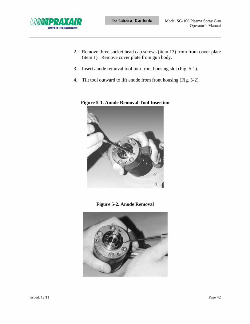
Model SG-100 Plasma Spray Gun Operator’s Manual
_____________________________________________________________________________________________________________________
Issued: 12/11 Page 42
2. Remove three socket head cap screws (item 13) from front cover plate (item 1). Remove cover plate from gun body.
3. Insert anode removal tool into front housing slot (Fig. 5-1). 4. Tilt tool outward to lift anode from front housing (Fig. 5-2).
Figure 5-1. Anode Removal Tool Insertion
Figure 5-2. Anode Removal
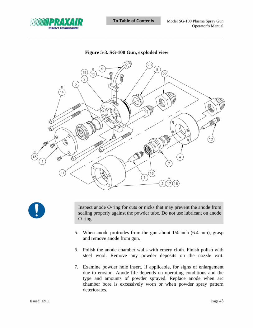
Model SG-100 Plasma Spray Gun Operator’s Manual
_____________________________________________________________________________________________________________________
Issued: 12/11 Page 43
Figure 5-3. SG-100 Gun, exploded view
Inspect anode O-ring for cuts or nicks that may prevent the anode from sealing properly against the powder tube. Do not use lubricant on anode O-ring.
5. When anode protrudes from the gun about 1/4 inch (6.4 mm), grasp
and remove anode from gun. 6. Polish the anode chamber walls with emery cloth. Finish polish with
steel wool. Remove any powder deposits on the nozzle exit.
7. Examine powder hole insert, if applicable, for signs of enlargement due to erosion. Anode life depends on operating conditions and the type and amounts of powder sprayed. Replace anode when arc chamber bore is excessively worn or when powder spray pattern deteriorates.
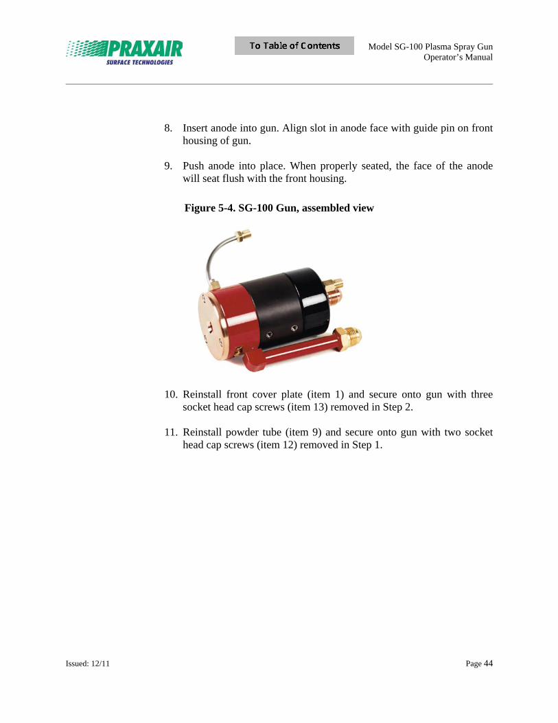
Model SG-100 Plasma Spray Gun Operator’s Manual
_____________________________________________________________________________________________________________________
Issued: 12/11 Page 44
8. Insert anode into gun. Align slot in anode face with guide pin on front
housing of gun. 9. Push anode into place. When properly seated, the face of the anode
will seat flush with the front housing.
Figure 5-4. SG-100 Gun, assembled view
10. Reinstall front cover plate (item 1) and secure onto gun with three socket head cap screws (item 13) removed in Step 2.
11. Reinstall powder tube (item 9) and secure onto gun with two socket
head cap screws (item 12) removed in Step 1.
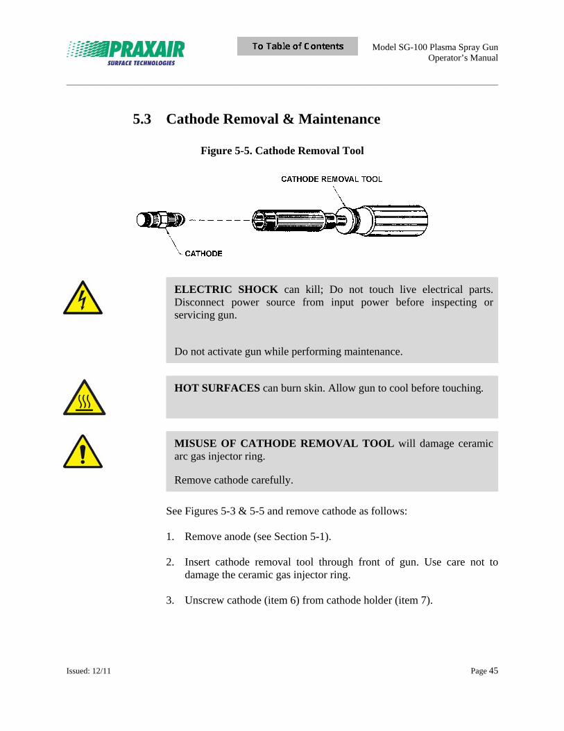
Model SG-100 Plasma Spray Gun Operator’s Manual
_____________________________________________________________________________________________________________________
Issued: 12/11 Page 45
5.3 Cathode Removal & Maintenance
Figure 5-5. Cathode Removal Tool
ELECTRIC SHOCK can kill; Do not touch live electrical parts. Disconnect power source from input power before inspecting or servicing gun.
Do not activate gun while performing maintenance.
HOT SURFACES can burn skin. Allow gun to cool before touching.
MISUSE OF CATHODE REMOVAL TOOL will damage ceramic arc gas injector ring.
Remove cathode carefully.
See Figures 5-3 & 5-5 and remove cathode as follows: 1. Remove anode (see Section 5-1). 2. Insert cathode removal tool through front of gun. Use care not to
damage the ceramic gas injector ring. 3. Unscrew cathode (item 6) from cathode holder (item 7).
Model SG-100 Plasma Spray Gun Operator’s Manual
_____________________________________________________________________________________________________________________
Issued: 12/11 Page 46
5.4 Complete SG-100 Disassembly & Maintenance
ELECTRIC SHOCK can kill. Do not touch live electrical parts. The gun is electrically “live” while power source is ON (approx. 32 VDC).
Disconnect input power before inspecting or servicing gun.
HOT SURFACES can burn skin. Allow gun to cool before touching.
Remove all power to system, see Figures 5-3 and 5-4, and disassemble SG-100 gun as follows: 1. Disconnect all hoses from gun body. 2. Remove the gun from the gun mount bracket. 3. Remove two socket head cap screws (item 12) from powder tube
(item 9). Remove powder tube. 4. Remove three socket head cap screws (item 13) from front cover plate
(item 1). Remove cover plate. 5. Remove four socket head cap screws (item 14) from front housing
(item 2). Remove rear insulator housing (item 4). 6. Firmly grasp cathode holder (item 7) and pull straight out from
insulator housing (item 3). 7. Gently twist and pull front housing (item 2) apart from insulator
housing (item 3). 8. Push anode (item 5) out of front housing (item 2) from rear. 9. Remove O-rings (items 15, 17, and 18) from insulator housing.
Model SG-100 Plasma Spray Gun Operator’s Manual
_____________________________________________________________________________________________________________________
Issued: 12/11 Page 47
Perform these maintenance procedures when gun is fully disassembled: • Dress anode (see Section 5-2). • Polish cathode with emery cloth. • Check gas injector for signs of wear. Replace if required. • Check O-rings for signs of over heating, damage, or wear spots. Replace if required.
5.5 Complete SG-100 Gun Reassembly
See Figures 5-3 and 5-4, and reassemble SG-100 gun as follows: 1. Install gas injector (item 8) into insulator housing (item 3) with taper
toward rear of the insulator housing. 2. Install O-ring (item 18) in groove forward to gas injector (item 8). Be
sure O-ring seats properly in groove. 3. Be sure O-ring (item 19) on flange of front housing is properly seated
in groove. Press insulator housing onto front housing. Align water cooled power tube between four tapped mounting holes in insulator housing.
ELECTRIC SHOCK can kill. Do not turn power source ON during test procedure.
Powder tube can be installed into top or bottom powder inlet holes in front housing, or two powder tubes can be installed when using two powders. When using only one powder tube, be sure powder hole plug (item 11) and O-ring (P/N 02-006S) are installed in the powder tube inlet not being used.
Powder gas must be ON at all times when operating or test firing the SG-100 gun.
4. Install cathode (item 6) and cathode holder (item 7) into rear of
insulator housing (item 3). Push cathode holder firmly into place.
Model SG-100 Plasma Spray Gun Operator’s Manual
_____________________________________________________________________________________________________________________
Issued: 12/11 Page 48
5. Install rear insulator housing (item 4) onto insulator housing (item 3). Be sure O-ring (item 16) fits properly in detent of insulator housing.
6. Install four socket head cap screws (item 14) into holes in front housing (item 2). Tighten securely.
7. Install anode (item 5) into front housing (item 2). Align anode guide pin hole with guide pin in front housing.
8. Press anode (item 5) into front housing (item 2) until face of anode is flush with face of front housing.
9. Install front cover plate (item 1) onto front housing (item 2). Secure with three socket head cap screws (item 13).
10. Install powder tube (item 9) into front housing. Secure with two socket head cap screws (item 12).
11. Reinstall gun to mounting bracket. 12. Connect red Positive (+) cable and black Negative (-) cable to
appropriate connections (see Section 3). Tighten securely. 13. Connect Plasma Gas In hose to 3/8 in. Gas In fitting on gun and
tighten securely. 14. Turn water pump ON and run water through gun. 15. Set primary arc gas pressure to approximately 50 psig to run arc gas
through gun. (DO NOT TEST WITH SECONDARY GAS.)
16. Check gun and hose fittings for water leaks. Look for moisture near gun nozzle exit. If moisture remains after a few seconds, disassemble gun and check O-rings or look for improperly seated components.
17. Install insulator sleeves (located on one end of water-cooled cables) over gun fittings.
18. Install insulator sleeves (located on other end of water-cooled cables) over connections to high-frequency unit.
19. Connect Powder In hose to 3/8 in. fitting on powder tube and tighten securely.
Model SG-100 Plasma Spray Gun Operator’s Manual
_____________________________________________________________________________________________________________________
Issued: 12/11 Page 49
Section 6 Parts List
Inspect labels on this unit every six months for legibility. Maintain all precautionary labels in a clearly readable state and replace when necessary. See parts list for label part numbers.
6.1 SG-100 Plasma Spray Gun Assembly
Item Part Number Description Quantity
1 02083-730 Anode 1 2 02083-120 Cathode 1 3 03083-112 Gas Injector 1
The above standard set of hardware is recommended for most applications. It produces high deposit efficiency with medium porosity level in the coatings. Use of the 02083-730 version anode with tungsten insert (P/N 02083-730T2) will extend anode life when using Helium or Hydrogen as the secondary gas.
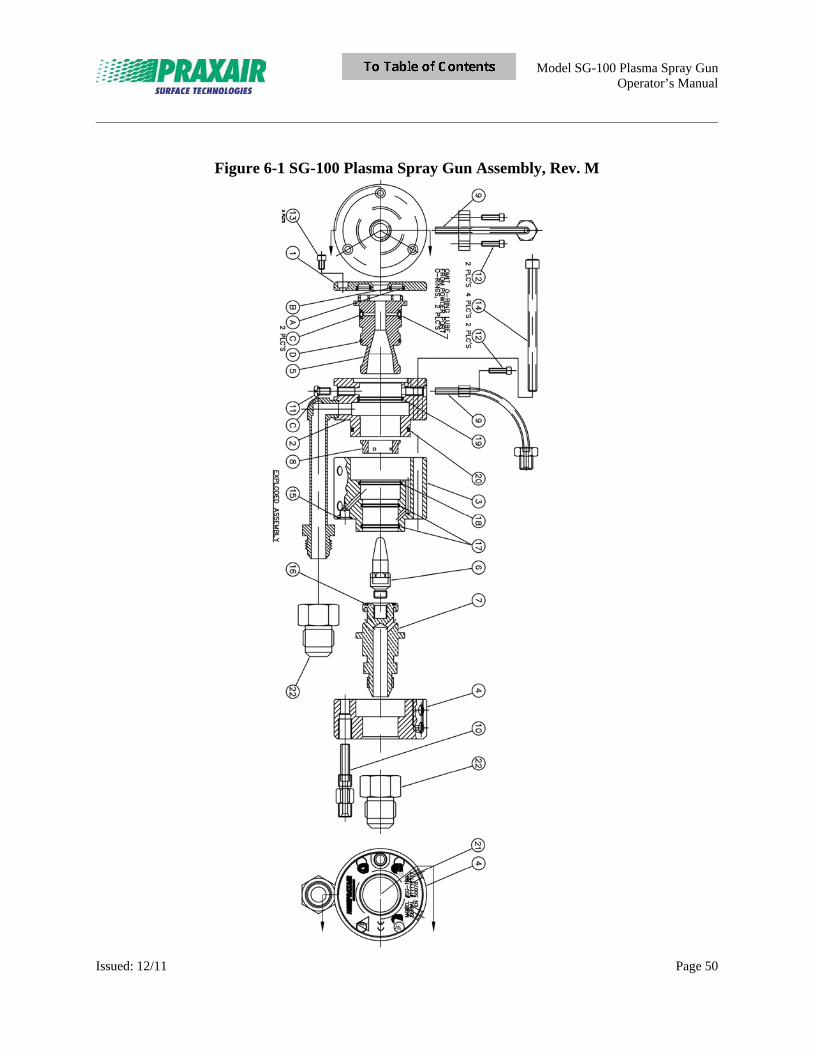
Model SG-100 Plasma Spray Gun Operator’s Manual
_____________________________________________________________________________________________________________________
Issued: 12/11 Page 50
Figure 6-1 SG-100 Plasma Spray Gun Assembly, Rev. M
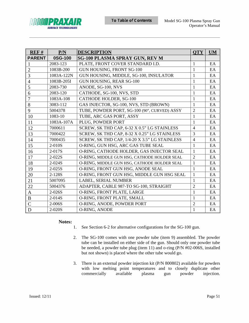
Model SG-100 Plasma Spray Gun Operator’s Manual
_____________________________________________________________________________________________________________________
Issued: 12/11 Page 51
REF # P/N DESCRIPTION QTY UM PARENT 0SG-100 SG-100 PLASMA SPRAY GUN, REV M 1 2083-123 PLATE, FRONT COVER STANDARD I.D. 1 EA 2 1083B-200 GUN HOUSING, FRONT SG-100 1 EA
3 1083A-122N GUN HOUSING, MIDDLE, SG-100, INSULATOR 1 EA 4 1083B-205I GUN HOUSING, REAR SG-100 1 EA 5 2083-730 ANODE, SG-100, NVS 1 EA
6 2083-120 CATHODE, SG-100, NVS, STD 1 EA 7 1083A-108 CATHODE HOLDER, SG-100 1 EA 8 3083-112 GAS INJECTOR, SG-100, NVS, STD (BROWN) 1 EA
9 5004378 TUBE, POWDER PORT, SG-100 (90°, CURVED) ASSY 2 EA 10 1083-10 TUBE, ARC GAS PORT, ASSY 1 EA 11 1083A-107A PLUG, POWDER PORT 1 EA
12 7000611 SCREW, SK THD CAP, 6-32 X 0.5” LG STAINLESS 4 EA 13 7000422 SCREW, SK THD CAP, 8-32 X 0.25” LG STAINLESS 3 EA 14 7000435 SCREW, SK THD CAP, 1/4-20 X 3.5” LG STAINLESS 4 EA 15 2-010S O-RING, GUN HSG, ARC GAS TUBE SEAL 1 EA
16 2-017S O-RING, CATHODE HOLDER, GAS INJECTOR SEAL 1 EA 17 2-022S O-RING, MIDDLE GUN HSG, CATHODE HOLDER SEAL 2 EA 18 2-024S O-RING, MIDDLE GUN HSG, CATHODE HOLDER SEAL 1 EA
19 2-025S O-RING, FRONT GUN HSG, ANODE SEAL 1 EA 20 2-128S O-RING, FRONT GUN HSG, MIDDLE GUN HSG SEAL 1 EA 21 5007095 LABEL, SERIAL NUMBER 1 EA
22 5004376 ADAPTER, CABLE 987-TO SG-100, STRAIGHT 2 EA A 2-026S O-RING, FRONT PLATE, LARGE 1 EA B 2-014S O-RING, FRONT PLATE, SMALL 1 EA
C 2-006S O-RING, ANODE, POWDER PORT 2 EA D 2-020S O-RING, ANODE 1 EA
Notes:
1. See Section 6-2 for alternative configurations for the SG-100 gun. 2. The SG-100 comes with one powder tube (item 9) assembled. The powder
tube can be installed on either side of the gun. Should only one powder tube be needed, a powder tube plug (item 11) and o-ring (P/N #02-006S, installed but not shown) is placed where the other tube would go.
3. There is an external powder injection kit (P/N 800802) available for powders
with low melting point temperatures and to closely duplicate other commercially available plasma gun powder injection.
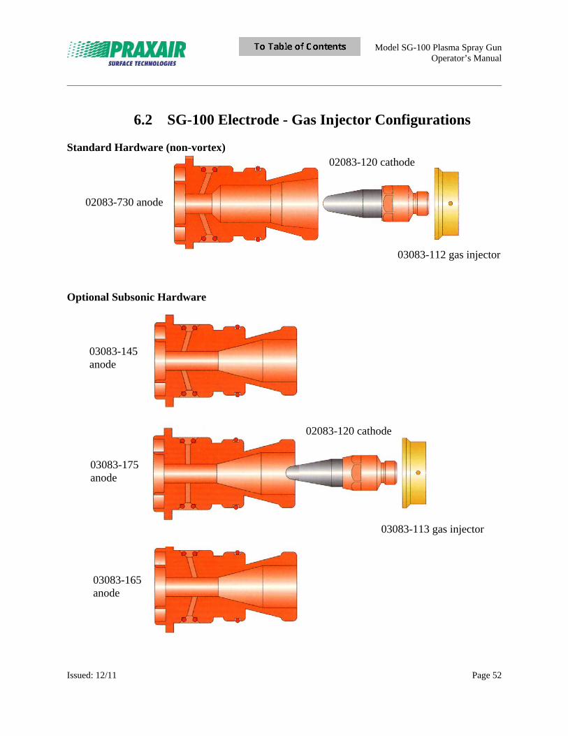
Model SG-100 Plasma Spray Gun Operator’s Manual
_____________________________________________________________________________________________________________________
Issued: 12/11 Page 52
6.2 SG-100 Electrode - Gas Injector Configurations
Standard Hardware (non-vortex)
Optional Subsonic Hardware
03083-145 anode
03083-175 anode
03083-165 anode
03083-113 gas injector
02083-730 anode
02083-120 cathode
03083-112 gas injector
02083-120 cathode
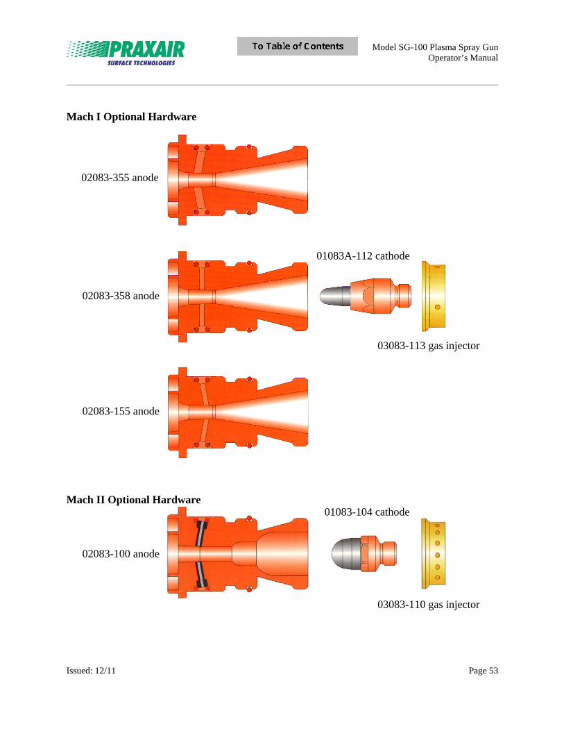
Model SG-100 Plasma Spray Gun Operator’s Manual
_____________________________________________________________________________________________________________________
Issued: 12/11 Page 53
Mach I Optional Hardware
Mach II Optional Hardware
03083-113 gas injector
02083-355 anode
02083-358 anode
02083-155 anode
02083-100 anode
03083-110 gas injector
01083A-112 cathode
01083-104 cathode
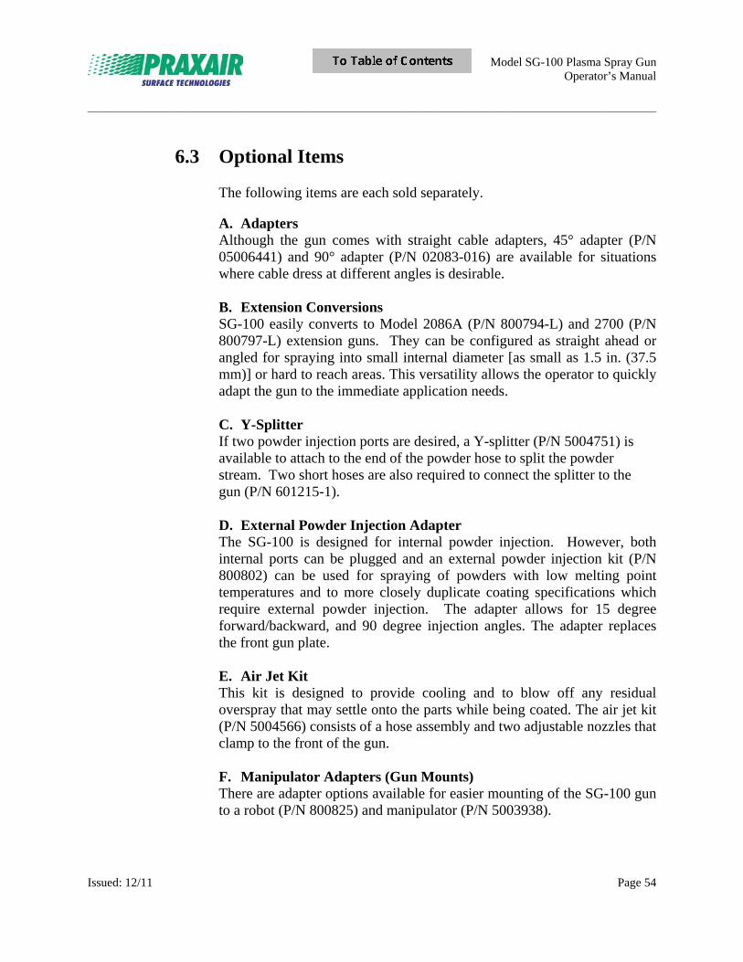
Model SG-100 Plasma Spray Gun Operator’s Manual
_____________________________________________________________________________________________________________________
Issued: 12/11 Page 54
6.3 Optional Items The following items are each sold separately.
A. Adapters Although the gun comes with straight cable adapters, 45° adapter (P/N 05006441) and 90° adapter (P/N 02083-016) are available for situations where cable dress at different angles is desirable. B. Extension Conversions SG-100 easily converts to Model 2086A (P/N 800794-L) and 2700 (P/N 800797-L) extension guns. They can be configured as straight ahead or angled for spraying into small internal diameter [as small as 1.5 in. (37.5 mm)] or hard to reach areas. This versatility allows the operator to quickly adapt the gun to the immediate application needs. C. Y-Splitter If two powder injection ports are desired, a Y-splitter (P/N 5004751) is available to attach to the end of the powder hose to split the powder stream. Two short hoses are also required to connect the splitter to the gun (P/N 601215-1). D. External Powder Injection Adapter The SG-100 is designed for internal powder injection. However, both internal ports can be plugged and an external powder injection kit (P/N 800802) can be used for spraying of powders with low melting point temperatures and to more closely duplicate coating specifications which require external powder injection. The adapter allows for 15 degree forward/backward, and 90 degree injection angles. The adapter replaces the front gun plate. E. Air Jet Kit This kit is designed to provide cooling and to blow off any residual overspray that may settle onto the parts while being coated. The air jet kit (P/N 5004566) consists of a hose assembly and two adjustable nozzles that clamp to the front of the gun. F. Manipulator Adapters (Gun Mounts) There are adapter options available for easier mounting of the SG-100 gun to a robot (P/N 800825) and manipulator (P/N 5003938).
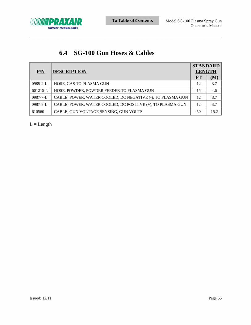
Model SG-100 Plasma Spray Gun Operator’s Manual
_____________________________________________________________________________________________________________________
Issued: 12/11 Page 55
6.4 SG-100 Gun Hoses & Cables
P/N DESCRIPTION STANDARD
LENGTH FT (M)
0985-2-L HOSE, GAS TO PLASMA GUN 12 3.7
601215-L HOSE, POWDER, POWDER FEEDER TO PLASMA GUN 15 4.6
0987-7-L CABLE, POWER, WATER COOLED, DC NEGATIVE (-), TO PLASMA GUN 12 3.7
0987-8-L CABLE, POWER, WATER COOLED, DC POSITIVE (+), TO PLASMA GUN 12 3.7
610560 CABLE, GUN VOLTAGE SENSING, GUN VOLTS 50 15.2
L = Length

Model SG-100 Plasma Spray Gun Operator’s Manual
_____________________________________________________________________________________________________________________
Issued: 12/11 Page 56
Notes

Praxair Surface Technologies, Inc. 146 Pembroke Road Concord, NH 03301 www.praxairsurfacetechnologies.com [email protected] Telephone: 1-603-224-9585 Fax: 1-603-225-4342