Embed Size (px)
Citation preview
User’sManual
IM 12D03D02-01E
Model SC72Personal Conductivity Meter
IM 12D03D02-01E3rd Edition
1
Preface
IM 12D03D02-01E3rd Edition: Aug. 2009 (YK)All Rights Reserved, Copyright © 2004, Yokogawa Electric Corporation
Preface
Before using the Model SC72 Personal Conductivity Meter, read this manual thoroughly.
For safe use of this meter, the meter and the instruction manual include the followingsymbol marks.
WARNING : Indicates that serious injury may result, if users fail to follow
instruction manual procedures.
CAUTION : Indicates that minor injury to personnel, or serious damage to
the product, may result if users fail to follow procedures in the
instruction manual.
WARNING
Do NOT use this instrument where there is a possibility of electrical shock.
Do NOT touch any part of the electrode immediately after measuring very hot liquids —otherwise, you may get burnt.
CAUTIONIf the meter will not be used for an extended period of time, be sure to remove thebattery. Otherwise battery leakage may occur, and may cause damage to the meter orcause erroneous meter operation.
The contents of this manual are subject to change without prior notice.
Yokogawa Electric Corporation assumes no liability for damage, defects, or loss of theproduct caused by any of the following:
User error;
Inappropriate or out-of-specifications use of the product;
Use in an unsuitable environment;
Repair or modification of this or related products by persons other than Yokogawa-authorized engineers.
IM 12D03D02-01E2
Preface
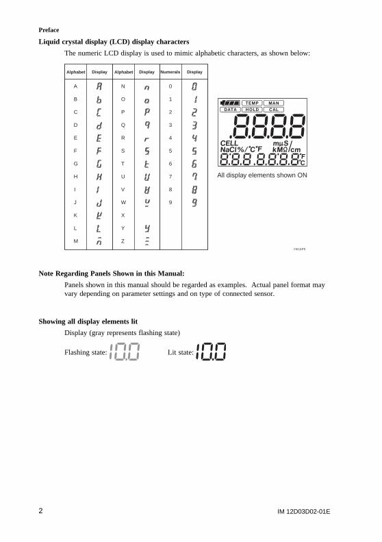
Liquid crystal display (LCD) display characters
The numeric LCD display is used to mimic alphabetic characters, as shown below:
9
8
7
6
5
4
3
2
1
0
Z
Y
X
W
V
U
T
S
R
Q
P
O
N
M
L
K
J
I
H
G
F
E
D
C
B
A
Alphabet Displa y Alphabet Displa y Displa yNumerals
F00.EPS
All display elements shown ON
Note Regarding Panels Shown in this Manual:
Panels shown in this manual should be regarded as examples. Actual panel format mayvary depending on parameter settings and on type of connected sensor.
Showing all display elements lit
Display (gray represents flashing state)
Flashing state: Lit state:
IM 12D03D02-01E 3
Preface
Warranty and Service
Yokogawa products and parts are guaranteed to be free from defects in workmanship andmaterials under normal use and service for a period of (typically) 12 months from thedate of shipment from the manufacturer.
Individual sales units may offer different warranty periods, so the original purchase ordershould be consulted for the conditions of sale. Damage caused by normal wear and tear,inadequate maintenance, corrosion, or due to chemical processes, is excluded from thiswarranty coverage.
In the event of a warranty claim, any items that are considered to be defective should besent (freight paid) for repair or replacement (at Yokogawa discretion) to the servicedepartment of the relevant sales unit. The following information must be included in aletter accompanying the returned items:
Model code and serial number
Copy of original purchase order showing the date
Length of time used, and the measuring environment
Fault symptoms, and circumstances of failure
Statement whether service under warranty or out-of-warranty service is requested
Complete shipping and billing instructions for return of goods, plus the name andphone number of a contact person who can be reached for further information
Goods that have been in contact with process fluids must be decontaminated / disinfectedbefore shipment, and a statement to this effect should be included. Safety data sheets forall process components that the goods have exposed to should also be included.
IM 12D03D02-01E4
Contents
CONTENTS
Preface ...................................................................................................................... 1-1
1. Outline ................................................................................................................. 1-11.1 Features ......................................................................................................................... 1-11.2 Personal Conductivity Meter Specifications .................................................................. 1-21.3 When You Receive This Conductivity Meter ................................................................. 1-31.4 Contents of Model SC72 Personal Conductivity Meter Package ................................. 1-41.5 Component Names and Functions ................................................................................ 1-51.6 Sensor Part Names and Functions ............................................................................... 1-61.7 Options (Available Separately) ...................................................................................... 1-81.8 Spare Parts .................................................................................................................... 1-8
2. Preparation .......................................................................................................... 2-12.1 Installing the Batteries ................................................................................................... 2-12.2 Connecting Sensor Cable .............................................................................................. 2-22.3 Setting Date and Time ................................................................................................... 2-32.4 Setting Temperature Unit .............................................................................................. 2-42.5 Setting Cell Constant ..................................................................................................... 2-42.6 Setting Temperature Compensation Coefficient ........................................................... 2-6
3. Measurement ...................................................................................................... 3-13.1 Precautions .................................................................................................................... 3-13.2 Measurement Procedures ............................................................................................. 3-23.3 Measurement Panel ....................................................................................................... 3-33.4 Saving Measured Value ................................................................................................ 3-3
4. Keyswitch Functions .......................................................................................... 4-14.1 Names and Functions of Keys ...................................................................................... 4-24.2 Liquid Crystal Display and Display Items ...................................................................... 4-44.3 Function Modes ............................................................................................................. 4-5
5. Handling of the SC72 Personal Conductivity Meter ........................................ 5-15.1 Tips to Maintain Meter Performance ............................................................................. 5-15.2 Washing the Electrode .................................................................................................. 5-25.3 Cleaning and Drying Connector .................................................................................... 5-35.4 Calibration with Standard Solution ................................................................................ 5-45.5 Storage and Maintenance ............................................................................................. 5-7
6. Troubleshooting ................................................................................................. 6-16.1 Causes of Abnormal Conductivity Display .................................................................... 6-16.2 Error Messages and Corrective Action ......................................................................... 6-26.3 Causes of Abnormal Measured Value .......................................................................... 6-46.4 Other conditions ............................................................................................................. 6-4
7. Measuring Principles of this Instrument .......................................................... 7-17.1 What Is Conductivity? .................................................................................................... 7-17.2 Principles of Operation .................................................................................................. 7-27.3 Temperature Compensation and Finding Temperature Compensation Coefficient ..... 7-37.4 Wetted Part Materials of Sensors ................................................................................. 7-4
Appendix ..................................................................................................................... 1
Revision Record .......................................................................................................... i
IM 12D03D02-01E 1-1
1. Outline
1. Outline
The Model SC72 Personal Conductivity Meter is an accurate, portable, easy-to-useconductivity meter. It includes not only self-diagnostic functions, to help ensure validityof readings, but also data storage functions to allow users to check past data. The meteris of waterproof construction so that it can safely be used outdoors on a rainy day, andcan also withstand being accidentally dropped into water.
1.1 Features
Water resistant caseWhen this meter is used with its dedicated sensor, it meets the requirements of class IP67“Degree of Protection to be Provided by Enclosures” in IEC 60529.
Wide measurement range, and convenient “Auto Range” functionSensors are available to cover measurement ranges between 0 to 2.000 mS/cm and 0 to 2S/cm. Auto-range functions automatically set the optimum measurement range, makingmeasurement easy.
Automatic temperature compensationAutomatic temperature compensation functions are provided for liquid measurement.Conductivity referenced to 258C can be obtained in solutions with temperaturecoefficients between 0.00 and 9.99%/8C. The temperature coefficients for NaCl solutionsare already stored in the meter.
Calendar and time functionsInternal time functions allow “one-touch checking” of measurement date and time.
Data storage functionUp to 300 conductivities and temperature measurements, and their measurement date andtime, can be saved. This function allows you to check past measurement data.
Automatic power off functionThe meter will power off automatically if not operated during a preset time interval.
The time interval can be set in one-minute increments in the range 1 to 120 minutes tomeet your application requirements. This automatic power off function can also bedisabled, but it is wise to leave it enabled to conserve the batteries.
Simple alarm clock functionThe meter can issue an alarm signal at a specified time. Even when meter power isturned off, the internal clock can issue an alarm signal.
Internal self-diagnostic functions display messages when appropriate.
Bright easy-to view large LCDDisplays liquid conductivity, liquid temperature, temperature coefficient, date and time.
IM 12D03D02-01E1-2
1. Outline
1.2 Personal Conductivity Meter SpecificationsApplicable measurement range:
• Sensors for high purity water measurement (cell constant: 0.05 cm-1)
Conductivity: 0 to 2mS/cm, 0 to 20mS/cm, 0 to 200mS/cm, 0 to 40MV•cm
Temperature: 0 to 808C*1
• For general-purpose sensors (cell constant: 5 cm-1)
Conductivity: 0 to 20mS/cm, 0 to 200mS/cm, 0 to 2mS/cm, 0 to 20mS/cm,0 to 200mS/cm,
Temperature: 0 to 808C*1
• For chemical-corrosion-resistant sensors (cell constant: 5 cm-1)
Conductivity: 0 to 20mS/cm, 0 to 200mS/cm, 0 to 2mS/cm, 0 to 20mS/cm,0 to 200mS/cm
Temperature: 0 to 808C*1
• Sensors for high-conductivity measurement (cell constant: 50 cm-1)
Conductivity: 0 to 2mS/cm, 0 to 20mS/cm, 0 to 200mS/cm, 0 to 2S/cm
Temperature: 0 to 808C*1
Resolution: Conductivity: Least significant digit: 1 digit;
Temperature: 0.18C
Repeatability (Conductivity):
62% (65% for general-purpose sensor on 0 to 200mS/cm measurement range)
Accuracy (Temperature):60.78C (in the range 0 to 708C)
618C (when exceeding 708C)
Temperature compensation range:
variable 0.00 to 9.99%/8C, also (preset) NaCl solution temperature coefficient
Measurement converted to conductivity at standard temperature of 258C
Measured liquid temperature: 0 to 808C (0 to 508C when the sensor cable is immersed inwater)
Ambient temperature:0 to 508C
Construction: IEC 60529, IP67 class of protection from environment
Power requirement: Two of size AA batteries (LR6)
Automatic power off interval: May be set in range 1 to 120 minutes
Battery life: About 200 hours of continuous use, for long-life alkaline battery (lifemay vary depending on battery type and ambient conditions)
External dimensions: Approximately 150 (H) x 61 (W) x 42 (D) mm (not includingprotruding portions)
Weight: Approximately 220 g (including batteries)
*1: Display range is from -10 to 1208C.
IM 12D03D02-01E 1-3
1. Outline
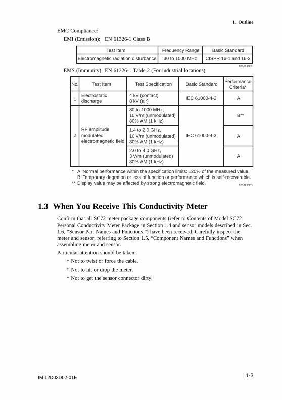
EMC Compliance:
EMI (Emission): EN 61326-1 Class B
Test Item
Electromagnetic radiation disturbance
Frequency Range
30 to 1000 MHz
Basic Standard
CISPR 16-1 and 16-2
T0101.EPS
EMS (Immunity): EN 61326-1 Table 2 (For industrial locations)
Test ItemNo.
1Electrostatic discharge
Test Specification Basic Standard
IEC 61000-4-2
PerformanceCriteria*
* A: Normal performance within the specification limits: ±20% of the measured value. B: Temporary degration or less of function or performance which is self-recoverable.** Display value may be affected by strong electromagnetic field.
A4 kV (contact)8 kV (air)
A2.0 to 4.0 GHz,3 V/m (unmodulated)80% AM (1 kHz)
2RF amplitude modulated electromagnetic field
IEC 61000-4-3
B**80 to 1000 MHz,10 V/m (unmodulated)80% AM (1 kHz)
A1.4 to 2.0 GHz,10 V/m (unmodulated)80% AM (1 kHz)
T0102.EPS
1.3 When You Receive This Conductivity MeterConfirm that all SC72 meter package components (refer to Contents of Model SC72Personal Conductivity Meter Package in Section 1.4 and sensor models described in Sec.1.6, “Sensor Part Names and Functions.”) have been received. Carefully inspect themeter and sensor, referring to Section 1.5, “Component Names and Functions” whenassembling meter and sensor.
Particular attention should be taken:
* Not to twist or force the cable.
* Not to hit or drop the meter.
* Not to get the sensor connector dirty.
IM 12D03D02-01E1-4
1. Outline
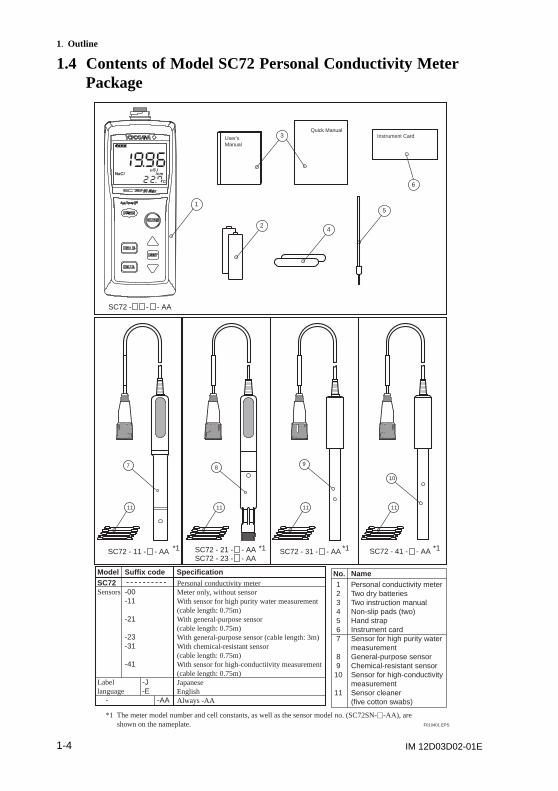
1.4 Contents of Model SC72 Personal Conductivity MeterPackage
11 11 11 11
Instrument Card
7 89
10
1
2
5
6
4
3Quick Manual
User'sManual
SC72 - - - AA
SC72 - 11 - - AA SC72 - 31 - - AA SC72 - 41 - - AA*1 *1 *1 *1
*1 The meter model number and cell constants, as well as the sensor model no. (SC72SN-u-AA), are shown on the nameplate.
SC72 - 21 - - AASC72 - 23 - - AA
SC72Sensors -00 -11
-21
-23 -31
-41
Label -Jlanguage -E - -AA
Specification
1234567
89
10
11
No.Personal conductivity meterTwo dry batteriesTwo instruction manualNon-slip pads (two)Hand strapInstrument cardSensor for high purity water measurementGeneral-purpose sensorChemical-resistant sensorSensor for high-conductivity measurementSensor cleaner (five cotton swabs)
NameModel Suffix codePersonal conductivity meterMeter only, without sensorWith sensor for high purity water measurement (cable length: 0.75m)With general-purpose sensor (cable length: 0.75m)With general-purpose sensor (cable length: 3m)With chemical-resistant sensor (cable length: 0.75m)With sensor for high-conductiivity measurement (cable length: 0.75m)JapaneseEnglishAlways -AA
F010401.EPS
IM 12D03D02-01E 1-5
1. Outline
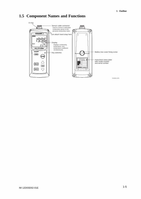
1.5 Component Names and Functions
PERSONALSC METER
2004.
SC72
S1.0
E000001
MODEL
No.
STYLE
Sensor cable connector
Display
Key switches
O-ring
Used to connect a dedicated conductivity sensor to the personal conductivity meter.
Displays conductivity, temperature, and temperature coefficient simultaneously.
Can attach hand strap here
Instrument name plate with model number and serial number
Battery box cover fixing screw
F010501.EPS
IM 12D03D02-01E1-6
1. Outline
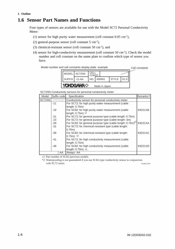
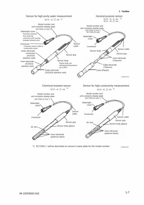
1.6 Sensor Part Names and FunctionsFour types of sensors are available for use with the Model SC72 Personal ConductivityMeter:
(1) sensor for high purity water measurement (cell constant 0.05 cm-1),
(2) general-purpose sensor (cell constant 5 cm-1),
(3) chemical-resistant sensor (cell constant 50 cm-1), and
(4) sensor for high-conductivity measurement (cell constant 50 cm-1). Check the modelnumber and cell constant on the name plate to confirm which type of sensor youhave.
Conductivity sensor for personal conductivity meterFor SC72; for high purity water measurement (cable length: 0.75m)For SC82; for high purity water measurement (cable length: 0.75m)For SC72; for general purpose type (cable length: 0.75m)For SC72; for general purpose type (cable length: 3m)For SC82; for general purpose type (cable length: 0.75m)For SC72; for chemical-resistant type (cable length: 0.75m)For SC82; for chemical-resistant type (cable length: 0.75m)For SC72; for high conductivity measurement (cable length: 0.75m)For SC82; for high conductivity measurement (cable length: 0.75m)Always -AA
SC72SN -11
-19
-21 -23 -29 -31
-39
-41
-49
-AA
Specification
K9221XB
K9221XA
K9221XC
K9221XD
RemarksModel Suffix code
Model number and cell constants display plate example
SC72SN Conductivity sensors for personal conductivity meter
F010601.EPS
*1
*2
*2
*2
*2
S1.0000001-11-AA STYLE
CELLCONST
Made in Japan
MODEL
SUFFIX NO.
SC72SN
Cell constants
*1: Part number of SC82 (previous model).*2: Waterproofing is not guaranteed if you use SC82-type conductivity sensor in conjunction
with SC72 meter.
IM 12D03D02-01E 1-7
1. Outline
F010602.EPS
Sensor for high purity water measurement
Outer electrode(SUS316 stainless seel)
Outer electrode connection
(SUS316 stainless seel)
Sensor body
Sensor gripSensor grip
Sensor cable
Watertight cover
Connector
Model number and cell constants display plate
Inner electrode(SUS316
stainless seel)
General-purpose sensor
Cover (Plastic)
Sensor bodySensor cable
Watertight cover
Connector
Model number and cell constants display plate
Edge electrode(Titanium)
Inner electrode(Titanium)
Prevents moisture from entering connector and causing leakage between pins.
Connects sensor cable to conductivity meter
Plastic body can withstand temperatures up to 808C.
SC72 - 11 - - AA *1
*1
*1SC72 - 21 - - AASC72 - 23 - - AA
(SC72SN-11-AA)*1(SC72SN-21-AA,
SC72SN-23-AA)
F010603.EPS
Chemical-resistant sensor
Inner electrode(platinum black)
Air vent Sensor body (glass)
Inner electrode(platinum black)
Air ventSensor body (glass)
Sensor cable
Watertight cover
Connector
Model number and cell constants display plate
Sensor for high-conductivity measurement
Sensor cable
Watertight cover
Connector
Model number and cell constants display plate
*1 SC72SN-u will be described on sensor's name plate for the model number.
SC72 - 31 - - AA SC72 - 41 - - AA*1 *1
Sensor gripSensor grip
*1(SC72SN-31-AA)*1(SC72SN-41-AA)
IM 12D03D02-01E1-8
1. Outline
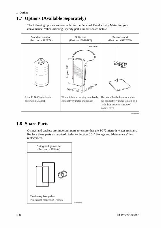
1.7 Options (Available Separately)The following options are available for the Personal Conductivity Meter for yourconvenience. When ordering, specify part number shown below.
Sensor stand(Part no.: K9220XN)
Soft case(Part no.: B9269KJ)
Standard solution(Part no.: K9221ZA)
This stand holds the sensor when the conductivity meter is used on a table. It is made of rustproof stailess steel.
0.1mol/l NaCl solution for calibration (250ml)
This soft black carrying case holds conductivity meter and sensor.
Unit: mm
Approx. 30
Approx. 140
App
rox.
280
F010701.EPS
1.8 Spare PartsO-rings and gaskets are important parts to ensure that the SC72 meter is water resistant.Replace these parts as required. Refer to Section 5.5, “Storage and Maintenance” forreplacement.
O-ring and gasket set(Part no.: K9654AY)
Two battery box gasketsTwo sensor connection O-rings
F010801.EPS
IM 12D03D02-01E 2-1
2. Preparation
2. Preparation
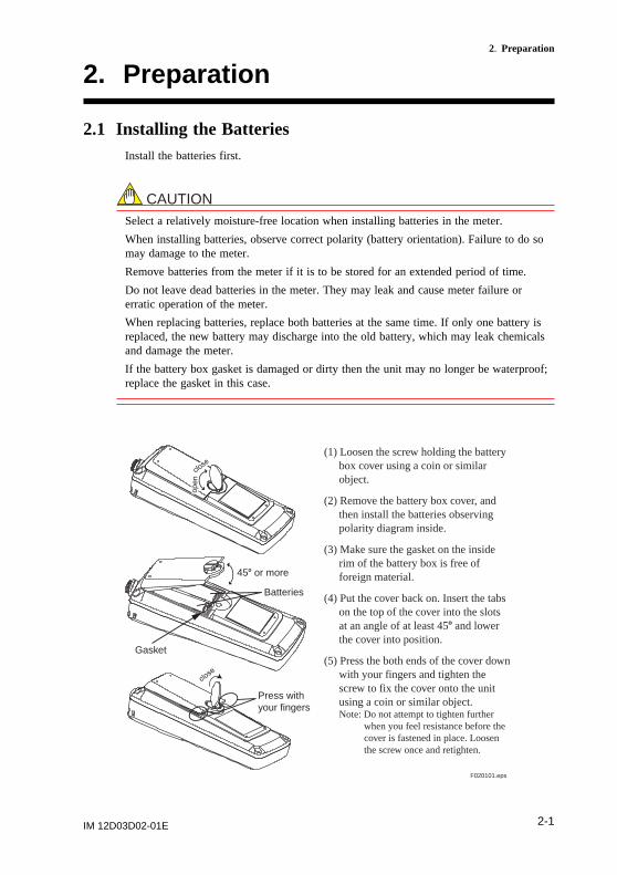
2.1 Installing the BatteriesInstall the batteries first.
CAUTIONSelect a relatively moisture-free location when installing batteries in the meter.
When installing batteries, observe correct polarity (battery orientation). Failure to do somay damage to the meter.
Remove batteries from the meter if it is to be stored for an extended period of time.
Do not leave dead batteries in the meter. They may leak and cause meter failure orerratic operation of the meter.
When replacing batteries, replace both batteries at the same time. If only one battery isreplaced, the new battery may discharge into the old battery, which may leak chemicalsand damage the meter.
If the battery box gasket is damaged or dirty then the unit may no longer be waterproof;replace the gasket in this case.
F020101.eps
Press with your fingers
Gasket
Batteries
(1) Loosen the screw holding the battery box cover using a coin or similar object.
(2) Remove the battery box cover, and then install the batteries observing polarity diagram inside.
(3) Make sure the gasket on the inside rim of the battery box is free of foreign material.
(4) Put the cover back on. Insert the tabs on the top of the cover into the slots at an angle of at least 458 and lower the cover into position.
(5) Press the both ends of the cover down with your fingers and tighten the screw to fix the cover onto the unit using a coin or similar object.Note: Do not attempt to tighten further
when you feel resistance before the cover is fastened in place. Loosen the screw once and retighten.
458 or more
IM 12D03D02-01E2-2
2. Preparation
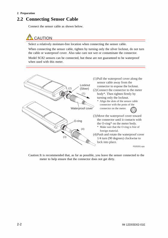
2.2 Connecting Sensor CableConnect the sensor cable as shown below.
CAUTIONSelect a relatively moisture-free location when connecting the sensor cable.
When connecting the sensor cable, tighten by turning only the silver locknut, do not turnthe cable or waterproof cover. Also take care not wet or contaminate the connector.
Model SC82 sensors can be connected, but these are not guaranteed to be waterproofwhen used with this meter.
F020201.eps
O-ring
(1) Pull the waterproof cover along the sensor cable away from the connector to expose the locknut.
(2) Connect the connector to the meter body*. Then tighten firmly by turning only the locknut.* Align the slots of the sensor cable
connector with the posts of the connector on the meter.
(3) Move the waterproof cover toward the connector until it contacts with the O-ring* on the meter body.* Make sure that the O-ring is free of
foreign material.(4) Push and rotate the waterproof cover
1/4 turn (90 degrees) clockwise to lock into place.
Locknut(Silver)
Waterproof cover
(1)
(2)
(4)
(3)
Caution:It is recommended that, as far as possible, you leave the sensor connected to themeter to help ensure that the connector does not get dirty.
IM 12D03D02-01E 2-3
2. Preparation
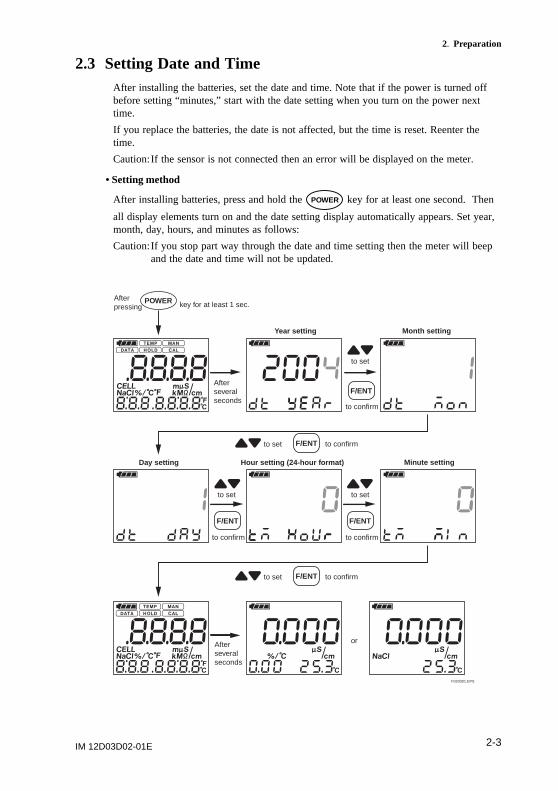
2.3 Setting Date and TimeAfter installing the batteries, set the date and time. Note that if the power is turned offbefore setting “minutes,” start with the date setting when you turn on the power nexttime.
If you replace the batteries, the date is not affected, but the time is reset. Reenter thetime.
Caution:If the sensor is not connected then an error will be displayed on the meter.
• Setting method
After installing batteries, press and hold the POWER key for at least one second. Then
all display elements turn on and the date setting display automatically appears. Set year,month, day, hours, and minutes as follows:
Caution:If you stop part way through the date and time setting then the meter will beepand the date and time will not be updated.
F020301.EPS
key for at least 1 sec.After pressing
to set
to confirm
to set
to set
to confirm
to confirm
to set
to confirm
Year setting
Day setting Hour setting (24-hour fo rmat)
Month setting
Minute setting
Afterseveralseconds
Afterseveralseconds
POWER
F/ENT
F/ENT F/ENT
F/ENT
to set to confirm
or
F/ENT
IM 12D03D02-01E2-4
2. Preparation
2.4 Setting Temperature UnitDefault temperature units are 8C. To change to 8F, refer to Sec. 4.3 (13) Set temperatureunits (tP.U) panel.
2.5 Setting Cell ConstantEven for sensors of the same type, each sensor has its own distinct cell constant. So, setthe proper cell constant as indicated on the sensor cable.
Whenever sensors are replaced, be sure to change the cell constant setting in the meteraccordingly. Cell constants once set are stored in non-volatile memory and are not losteven when the batteries are replaced.
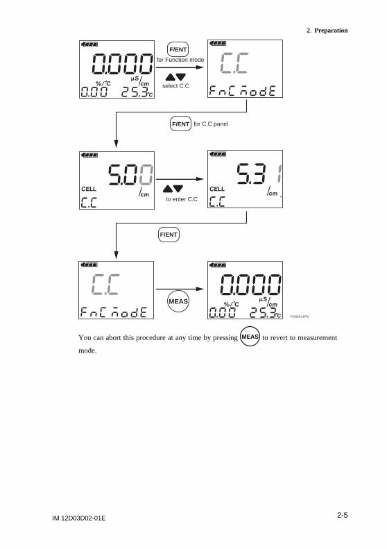
• Setting cell constants
Press the F/ENT key to switch to function mode. Then select the C.C display with the
key and access the cell constant setting display with the F/ENT key. Use the
key to set the cell constant, then press the F/ENT key to confirm it.
Refer to Sec. 4.3 (4).
IM 12D03D02-01E 2-5
2. Preparation
F020501.EPS
F/ENT
F/ENT
F/ENT
MEAS
for Function mode
for C.C panel
to enter C.C
select C.C
You can abort this procedure at any time by pressing MEAS to revert to measurement
mode.
IM 12D03D02-01E2-6
2. Preparation
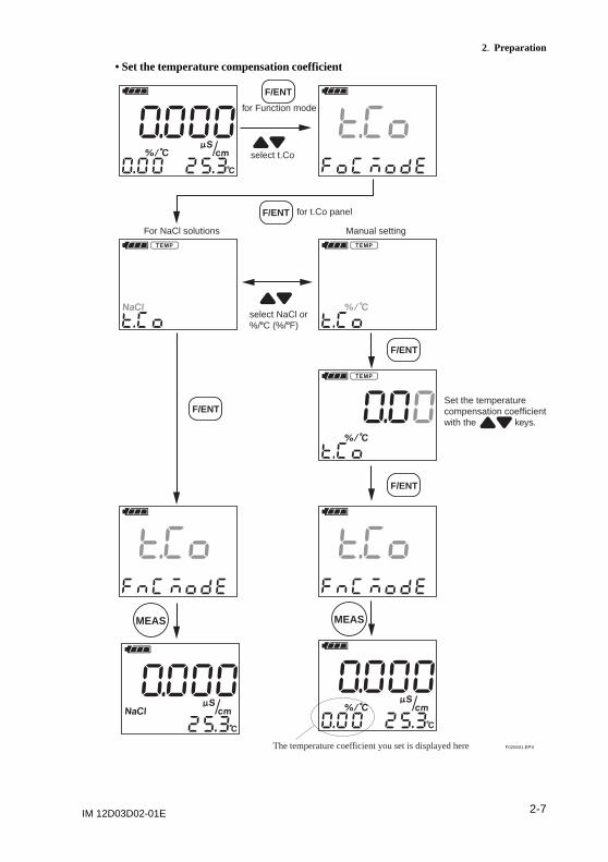
2.6 Setting Temperature Compensation CoefficientAs described in Section 7.3, liquid conductivity varies with liquid temperature.Therefore, if concentration is measured by conductivity, the conductivity must beconverted to equivalent conductivity at a certain temperature. This instrumentincorporates standard temperature conversion functions to convert liquid conductivitymeasurements to equivalent conductivity at 258C. To display equivalent liquidconductivity at 258C, set the temperature compensation coefficient as described in thissection.
Temperature coefficient for NaCl solutions is stored in this instrument. If any othersolution is used, set the temperature compensation coefficient manually.
Refer to Sec. 4.3 (2) Temperature compensation setting (t.Co) panel.
IM 12D03D02-01E 2-7
2. Preparation
• Set the temperature compensation coefficient
F020601.EPS
For NaCl solutions Manual setting
Set the temperaturecompensation coefficientwith the keys.
MEAS MEAS
F/ENT
F/ENT
F/ENT
F/ENT
F/ENT
The temperature coefficient you set is displayed here
for Function mode
for t.Co panel
select t.Co
select NaCl or%/8C (%/8F)

IM 12D03D02-01E2-8
2. Preparation
IM 12D03D02-01E 3-1
3. Measurement
3. Measurement
3.1 Precautions(1) Be sure to check that the cell constant and the temperature coefficient are set
correctly.
(2) Check that the plastic cover (for general-purpose sensor) and outer electrode (forhigh purity water measurement) are secure.
(3) Do not use the SC72 meter to measure liquids with temperatures over 808C. (If thesensor grip is immersed, liquid temperature shall be below 508C.) Do not use themeter to measure extremely corrosive liquids such as solutions of hydrofluoricacid.
(4) Remove dirt and stains from the meter with soft tissue. If necessary, wipe themeter case with neutral detergent.
(5) If any problem with the meter arises during measurement, refer to theTroubleshooting section later in this manual to determine the cause.
(6) After finishing measurement, flush stains on the sensor and measured solutionswith water, and store the meter (refer to Chapter 5, “Handling of the SC72Personal Conductivity Meter”).
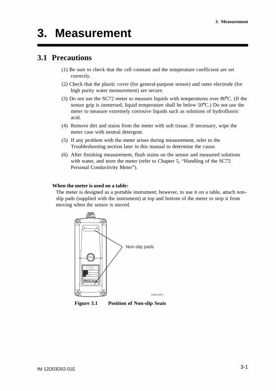
When the meter is used on a table:The meter is designed as a portable instrument; however, to use it on a table, attach non-slip pads (supplied with the instrument) at top and bottom of the meter to stop it frommoving when the sensor is moved.
SC METERPERSONAL
2004.
SC72
S1.0
E00000 1
M ODEL
No.
STYLE
Non-slip pads
F0301.EPS
Figure 3.1 Position of Non-slip Seats
IM 12D03D02-01E3-2
3. Measurement
3.2 Measurement Procedures
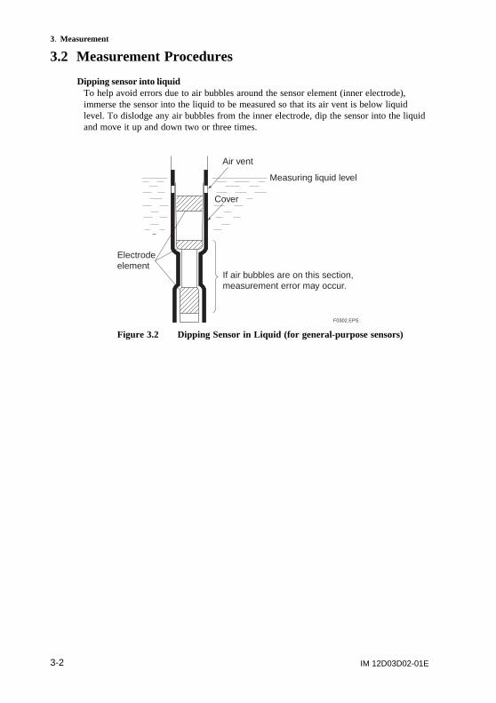
Dipping sensor into liquidTo help avoid errors due to air bubbles around the sensor element (inner electrode),immerse the sensor into the liquid to be measured so that its air vent is below liquidlevel. To dislodge any air bubbles from the inner electrode, dip the sensor into the liquidand move it up and down two or three times.
Air vent
Measuring liquid level
Cover
If air bubbles are on this section, measurement error may occur.
Electrode element
F0302.EPS
Figure 3.2 Dipping Sensor in Liquid (for general-purpose sensors)
IM 12D03D02-01E 3-3
3. Measurement
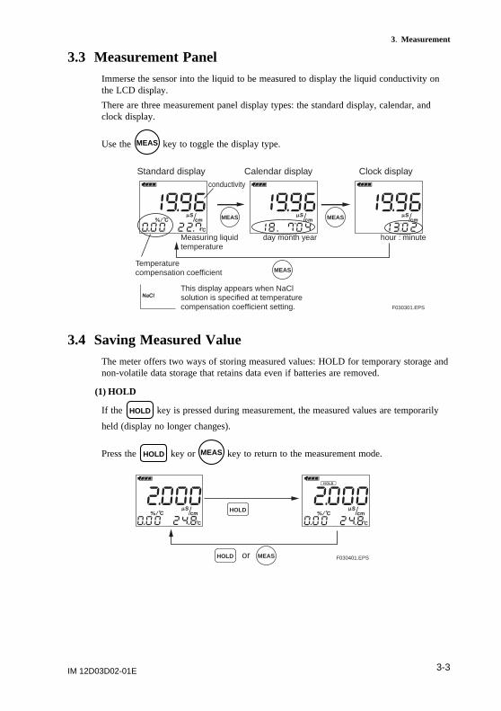
3.3 Measurement PanelImmerse the sensor into the liquid to be measured to display the liquid conductivity onthe LCD display.
There are three measurement panel display types: the standard display, calendar, andclock display.
Use the MEAS key to toggle the display type.
F030301.EPS
Standard display Calendar display Clock display
MEAS MEAS
MEAS
day month yearMeasuring liquid temperature
Temperature compensation coefficient
This display appears when NaCl solution is specified at temperature compensation coefficient setting.
conductivity
hour : minute
3.4 Saving Measured ValueThe meter offers two ways of storing measured values: HOLD for temporary storage andnon-volatile data storage that retains data even if batteries are removed.
(1) HOLD
If the HOLD key is pressed during measurement, the measured values are temporarily
held (display no longer changes).
Press the HOLD key or MEAS key to return to the measurement mode.
F030401.EPSorHOLD
HOLD
MEAS
IM 12D03D02-01E3-4
3. Measurement
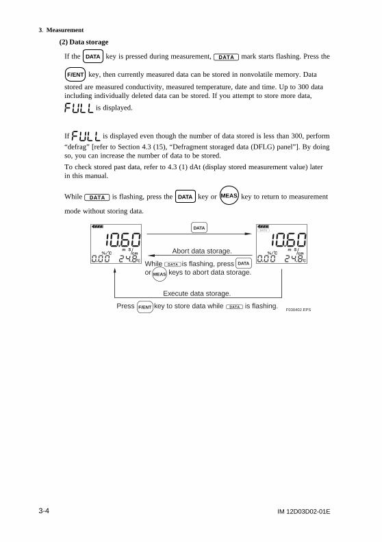
(2) Data storage
If the DATA key is pressed during measurement, mark starts flashing. Press the
F/ENT key, then currently measured data can be stored in nonvolatile memory. Data
stored are measured conductivity, measured temperature, date and time. Up to 300 dataincluding individually deleted data can be stored. If you attempt to store more data,
is displayed.
If is displayed even though the number of data stored is less than 300, perform
“defrag” [refer to Section 4.3 (15), “Defragment storaged data (DFLG) panel”]. By doingso, you can increase the number of data to be stored.
To check stored past data, refer to 4.3 (1) dAt (display stored measurement value) laterin this manual.
While is flashing, press the DATA key or MEAS key to return to measurement
mode without storing data.
F030402.EPS
Abort data storage.
Execute data storage.
Press key to store data while is flashing.
While is flashing, pressor keys to abort data storage.
F/ENT
MEAS
DATA
DATA
IM 12D03D02-01E 4-1
4. Keyswitch Functions
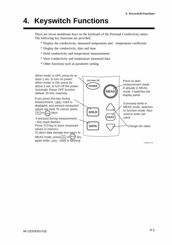
4. Keyswitch Functions
There are seven membrane keys on the keyboard of the Personal Conductivity meter.The following key functions are provided.
* Display the conductivity, measured temperature and temperature coefficient.
* Display the conductivity, date and time.
* Hold conductivity and temperature measurements.
* Store conductivity and temperature measured data.
* Other functions such as parameter setting.
POWER
Auto Power Off
HOLD
F/ENT
MEAS
DATA
F040001.EPS
When meter is OFF, press for at least 1 sec. to turn on power. When meter is ON, press for about 2 sec. to turn off the power. Automatic Power OFF function default: 20 min. inactivity.
Press to start measurement mode. If already in MEAS mode, it switches the display panel.
Change set value.
If pressed while in MEAS mode, switches to function mode. Also used to enter set value.
If you press this key during measurement, mark is displayed, and present measured values are held. To cancel, press or keys.
If pressed during measurement, mark flashes. Press key to store measured values in memory. To abort data storage and return to
MEAS mode, press or key again while mark is flashing.
MEAS
MEAS
F/ENT
HOLD
DATA
IM 12D03D02-01E4-2
4. Keyswitch Functions
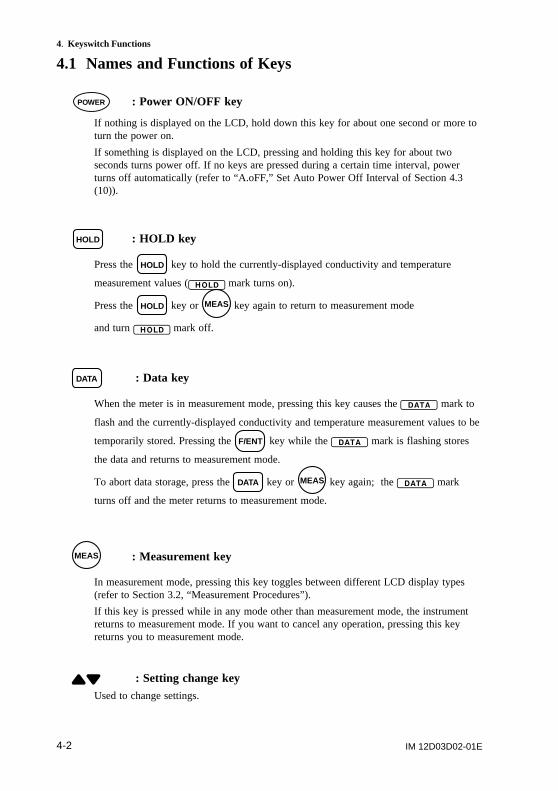
4.1 Names and Functions of Keys
POWER : Power ON/OFF key
If nothing is displayed on the LCD, hold down this key for about one second or more toturn the power on.
If something is displayed on the LCD, pressing and holding this key for about twoseconds turns power off. If no keys are pressed during a certain time interval, powerturns off automatically (refer to “A.oFF,” Set Auto Power Off Interval of Section 4.3(10)).
HOLD : HOLD key
Press the HOLD key to hold the currently-displayed conductivity and temperature
measurement values ( mark turns on).
Press the HOLD key or MEAS key again to return to measurement mode
and turn mark off.
DATA : Data key
When the meter is in measurement mode, pressing this key causes the mark to
flash and the currently-displayed conductivity and temperature measurement values to be
temporarily stored. Pressing the F/ENT key while the mark is flashing stores
the data and returns to measurement mode.
To abort data storage, press the DATA key or MEAS key again; the mark
turns off and the meter returns to measurement mode.
MEAS : Measurement key
In measurement mode, pressing this key toggles between different LCD display types(refer to Section 3.2, “Measurement Procedures”).
If this key is pressed while in any mode other than measurement mode, the instrumentreturns to measurement mode. If you want to cancel any operation, pressing this keyreturns you to measurement mode.
: Setting change keyUsed to change settings.
IM 12D03D02-01E 4-3
4. Keyswitch Functions
F/ENT : Entry key
In measurement mode, pressing this key switches the meter to function mode (seeSection 4.3, “Function Modes”). This key is also used to confirm set values.
Buzzer (Beep) soundWhen a key is pressed, the buzzer beeps. Where the buzzer beeps once, or when it beepsthree times continuously, the meaning is as follows:
(1) When the buzzer beeps once:This means that key operation was accepted.
(2) When the buzzer beeps three times continuously:This means that the key operation was not accepted.
To disable the above key entry beep, refer to Sec. 4.3 (11) Set buzzer ON/OFF (bZ.o)panel.
Note: the sound volume level of the beep cannot be adjusted by the user.
IM 12D03D02-01E4-4
4. Keyswitch Functions
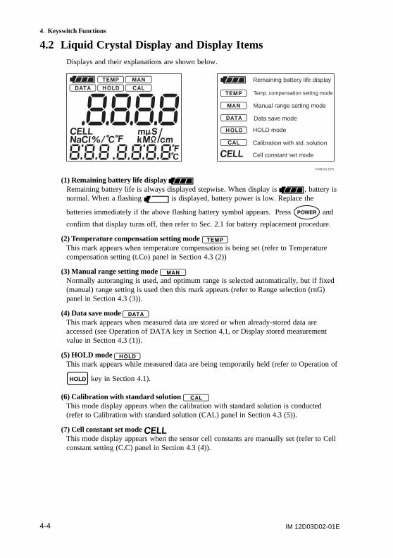
4.2 Liquid Crystal Display and Display ItemsDisplays and their explanations are shown below.
F040201.EPS
Remaining battery life display
Manual range setting mode
Temp. compensation setting mode
Data save mode
HOLD mode
Calibration with std. solution
Cell constant set mode
(1) Remaining battery life display Remaining battery life is always displayed stepwise. When display is , battery isnormal. When a flashing is displayed, battery power is low. Replace the
batteries immediately if the above flashing battery symbol appears. Press POWER and
confirm that display turns off, then refer to Sec. 2.1 for battery replacement procedure.
(2) Temperature compensation setting mode This mark appears when temperature compensation is being set (refer to Temperaturecompensation setting (t.Co) panel in Section 4.3 (2))
(3) Manual range setting mode Normally autoranging is used, and optimum range is selected automatically, but if fixed(manual) range setting is used then this mark appears (refer to Range selection (rnG)panel in Section 4.3 (3)).
(4) Data save mode This mark appears when measured data are stored or when already-stored data areaccessed (see Operation of DATA key in Section 4.1, or Display stored measurementvalue in Section 4.3 (1)).
(5) HOLD mode This mark appears while measured data are being temporarily held (refer to Operation of
HOLD key in Section 4.1).
(6) Calibration with standard solution This mode display appears when the calibration with standard solution is conducted(refer to Calibration with standard solution (CAL) panel in Section 4.3 (5)).
(7) Cell constant set mode This mode display appears when the sensor cell constants are manually set (refer to Cellconstant setting (C.C) panel in Section 4.3 (4)).
IM 12D03D02-01E 4-5
4. Keyswitch Functions
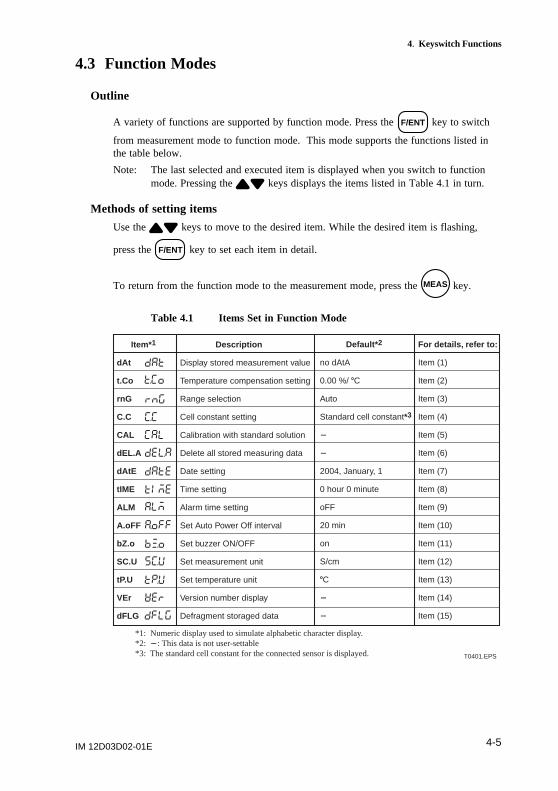
4.3 Function Modes
Outline
A variety of functions are supported by function mode. Press the F/ENT key to switch
from measurement mode to function mode. This mode supports the functions listed inthe table below.
Note: The last selected and executed item is displayed when you switch to functionmode. Pressing the keys displays the items listed in Table 4.1 in turn.
Methods of setting items
Use the keys to move to the desired item. While the desired item is flashing,
press the F/ENT key to set each item in detail.
To return from the function mode to the measurement mode, press the MEAS key.
Table 4.1 Items Set in Function Mode
Default* 2
no dAtA
0.00 %/ 8C
Auto
Standard cell constant*3
2
2
2004, January, 1
0 hour 0 minute
oFF
20 min
on
S/cm
8C
2
2
For details, refer to:
Item (1)
Item (2)
Item (3)
Item (4)
Item (5)
Item (6)
Item (7)
Item (8)
Item (9)
Item (10)
Item (11)
Item (12)
Item (13)
Item (14)
Item (15)
T0401.EPS
*1: Numeric display used to simulate alphabetic character display.*2: 2: This data is not user-settable*3: The standard cell constant for the connected sensor is displayed.
Item*1
dAt
t.Co
rnG
C.C
CAL
dEL.A
dAtE
tIME
ALM
A.oFF
bZ.o
SC.U
tP.U
VEr
dFLG
Description
Display stored measurement value
Temperature compensation setting
Range selection
Cell constant setting
Calibration with standard solution
Delete all stored measuring data
Date setting
Time setting
Alarm time setting
Set Auto Power Off interval
Set buzzer ON/OFF
Set measurement unit
Set temperature unit
Version number display
Defragment storaged data
IM 12D03D02-01E4-6
4. Keyswitch Functions
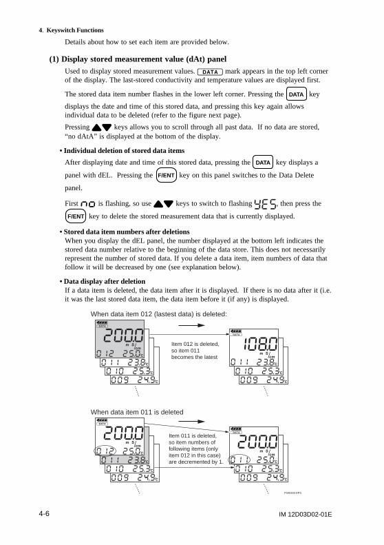
Details about how to set each item are provided below.
(1) Display stored measurement value (dAt) panelUsed to display stored measurement values. mark appears in the top left cornerof the display. The last-stored conductivity and temperature values are displayed first.
The stored data item number flashes in the lower left corner. Pressing the DATA key
displays the date and time of this stored data, and pressing this key again allowsindividual data to be deleted (refer to the figure next page).
Pressing keys allows you to scroll through all past data. If no data are stored,“no dAtA” is displayed at the bottom of the display.
• Individual deletion of stored data items
After displaying date and time of this stored data, pressing the DATA key displays a
panel with dEL. Pressing the F/ENT key on this panel switches to the Data Delete
panel.
First is flashing, so use keys to switch to flashing , then press the
F/ENT key to delete the stored measurement data that is currently displayed.
• Stored data item numbers after deletionsWhen you display the dEL panel, the number displayed at the bottom left indicates thestored data number relative to the beginning of the data store. This does not necessarilyrepresent the number of stored data. If you delete a data item, item numbers of data thatfollow it will be decreased by one (see explanation below).
• Data display after deletionIf a data item is deleted, the data item after it is displayed. If there is no data after it (i.e.it was the last stored data item, the data item before it (if any) is displayed.
When data item 012 (lastest data) is deleted:
When data item 011 is deleted
Item 012 is deleted, so item 011 becomes the latest
Item 011 is deleted, so item numbers of following items (only item 012 in this case) are decremented by 1.
F040300.EPS
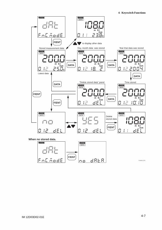
IM 12D03D02-01E 4-7
4. Keyswitch Functions
F040301.EPS
"Delete stored data" panel
Stored measurement data
to display other data
Latest data
Delete stored data
Year that data was storedDsy, month data was stored
Time stored
F/ENT
When no stored data.
F/ENT
F/ENT
F/ENT
F/ENT
DATA DATA
DATA
DATA
DATA
IM 12D03D02-01E4-8
4. Keyswitch Functions
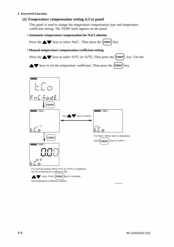
(2) Temperature compensation setting (t.Co) panelThis panel is used to change the temperature compensation type and temperaturecoefficient setting. The TEMP mark appears on the panel.
• Automatic temperature compensation for NaCl solution
Press the keys to select NaCl . Then press the F/ENT key.
• Manual temperature compensation coefficient setting
Press the keys to select %/8C (or %/8F). Then press the F/ENT key. Use the
keys to set the temperature coefficient. Then press the F/ENT key.
Use keys to select
For NaCl: When NaCl is displayed,
press key to confirm.F/ENT
F/ENT
F040302.EPS
For manual setting: When %/8C (or %/8F) is displayed, set the temperature coefficient with
keys. Press key to complete
the temperature coefficient setting.
F/ENT
F/ENT
IM 12D03D02-01E 4-9
4. Keyswitch Functions
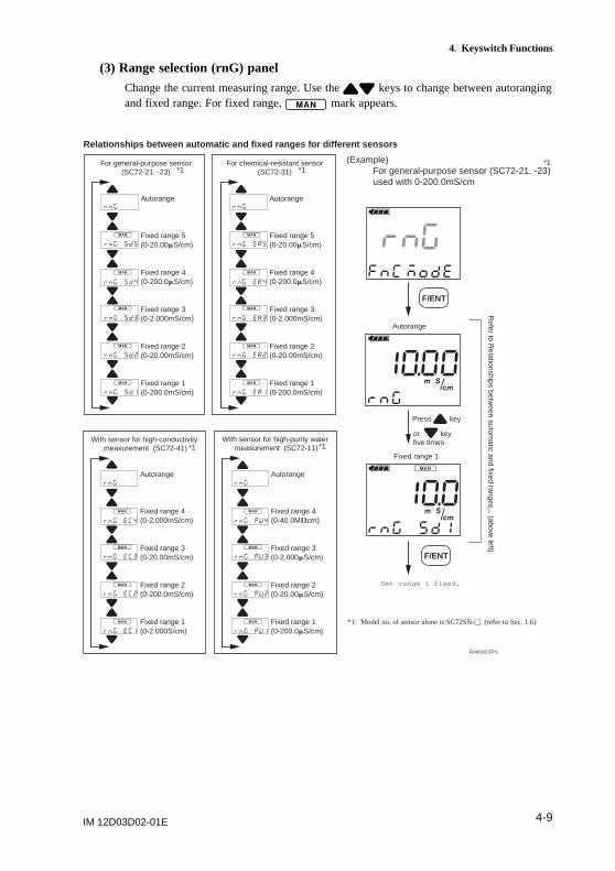
(3) Range selection (rnG) panel
Change the current measuring range. Use the keys to change between autorangingand fixed range. For fixed range, mark appears.
F040303.EPS
*1: Model no. of sensor alone is SC72SN-u. (refer to Sec. 1.6)
Press key
or key five times
Autorange
Fixed range 1
Relationships between automatic and fixed ranges for different sensors
For general-purpose sensor(SC72-21, -23)
(Example) For general-purpose sensor (SC72-21, -23) used with 0-200.0mS/cm
Autorange
Fixed range 5(0-20.00mS/cm)
Fixed range 4(0-200.0mS/cm)
Fixed range 3(0-2.000mS/cm)
Fixed range 2(0-20.00mS/cm)
Fixed range 1(0-200.0mS/cm)
For chemical-resistant sensor(SC72-31)
Autorange
Fixed range 5(0-20.00mS/cm)
Fixed range 4(0-200.0mS/cm)
Fixed range 3(0-2.000mS/cm)
Fixed range 2(0-20.00mS/cm)
Fixed range 1(0-200.0mS/cm)
With sensor for high-conductivity measurement (SC72-41)
Autorange
Fixed range 4(0-2.000mS/cm)
Fixed range 3(0-20.00mS/cm)
Fixed range 2(0-200.0mS/cm)
Fixed range 1(0-2.000S/cm)
With sensor for high-purity water measurement (SC72-11)
Autorange
Fixed range 4(0-40.0MVcm)
Fixed range 3(0-2.000mS/cm)
Fixed range 2(0-20.00mS/cm)
Fixed range 1(0-200.0mS/cm)
F/ENT
Set range 1 fixed.
F/ENT
*1 *1*1
*1 *1
Refer to R
elationships between autom
atic and fixed ranges... (above left)
IM 12D03D02-01E4-10
4. Keyswitch Functions
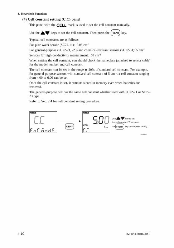
(4) Cell constant setting (C.C) panelThis panel with the mark is used to set the cell constant manually.
Use the keys to set the cell constant. Then press the F/ENT key.
Typical cell constants are as follows:
For pure water sensor (SC72-11): 0.05 cm-1
For general-purpose (SC72-21, -23) and chemical-resistant sensors (SC72-31): 5 cm-1
Sensors for high-conductivity measurement: 50 cm-1
When setting the cell constant, you should check the nameplate (attached to sensor cable)for the model number and cell constant.
The cell constant can be set in the range 6 20% of standard cell constant. For example,for general-purpose sensors with standard cell constant of 5 cm-1, a cell constant rangingfrom 4.00 to 6.00 can be set.
Once the cell constant is set, it remains stored in memory even when batteries areremoved.
The general-purpose cell has the same cell constant whether used with SC72-21 or SC72-23 type.
Refer to Sec. 2.4 for cell constant setting procedure.
F040304.EPS
Use key to set
the cell constant. Then press
the key to complete setting.F/ENT F/ENT
IM 12D03D02-01E 4-11
4. Keyswitch Functions
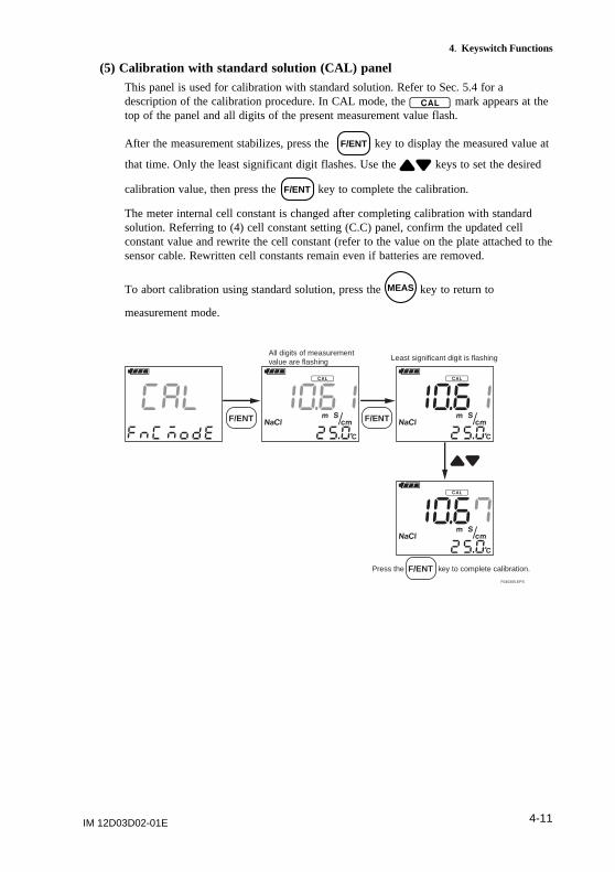
(5) Calibration with standard solution (CAL) panelThis panel is used for calibration with standard solution. Refer to Sec. 5.4 for adescription of the calibration procedure. In CAL mode, the mark appears at thetop of the panel and all digits of the present measurement value flash.
After the measurement stabilizes, press the F/ENT key to display the measured value at
that time. Only the least significant digit flashes. Use the keys to set the desired
calibration value, then press the F/ENT key to complete the calibration.
The meter internal cell constant is changed after completing calibration with standardsolution. Referring to (4) cell constant setting (C.C) panel, confirm the updated cellconstant value and rewrite the cell constant (refer to the value on the plate attached to thesensor cable. Rewritten cell constants remain even if batteries are removed.
To abort calibration using standard solution, press the MEAS key to return to
measurement mode.
F040305.EPS
All digits of measurement value are flashing Least significant digit is flashing
Press the key to complete calibration.F/ENT
F/ENTF/ENT
IM 12D03D02-01E4-12
4. Keyswitch Functions
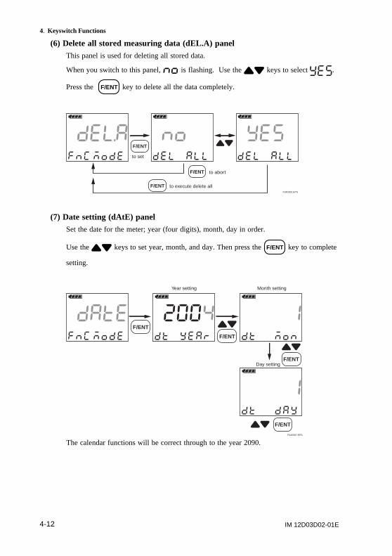
(6) Delete all stored measuring data (dEL.A) panelThis panel is used for deleting all stored data.
When you switch to this panel, is flashing. Use the keys to select .
Press the F/ENT key to delete all the data completely.
F040306.EPS
to set
F/ENT
to abortF/ENT
to execute delete allF/ENT
(7) Date setting (dAtE) panelSet the date for the meter; year (four digits), month, day in order.
Use the keys to set year, month, and day. Then press the F/ENT key to complete
setting.
F040307.EPS
Year setting Month setting
Day setting
F/ENT
F/ENT
F/ENT
F/ENT
The calendar functions will be correct through to the year 2090.
IM 12D03D02-01E 4-13
4. Keyswitch Functions
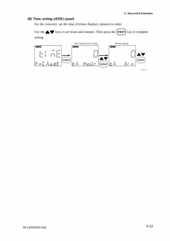
(8) Time setting (tIME) panelFor the converter, set the time (24-hour display), minutes in order.
Use the keys to set hours and minutes. Then press the F/ENT key to complete
setting.
F040308.EPS
Hour setting (24-hr clock) Minute setting
F/ENT F/ENT
F/ENT
IM 12D03D02-01E4-14
4. Keyswitch Functions
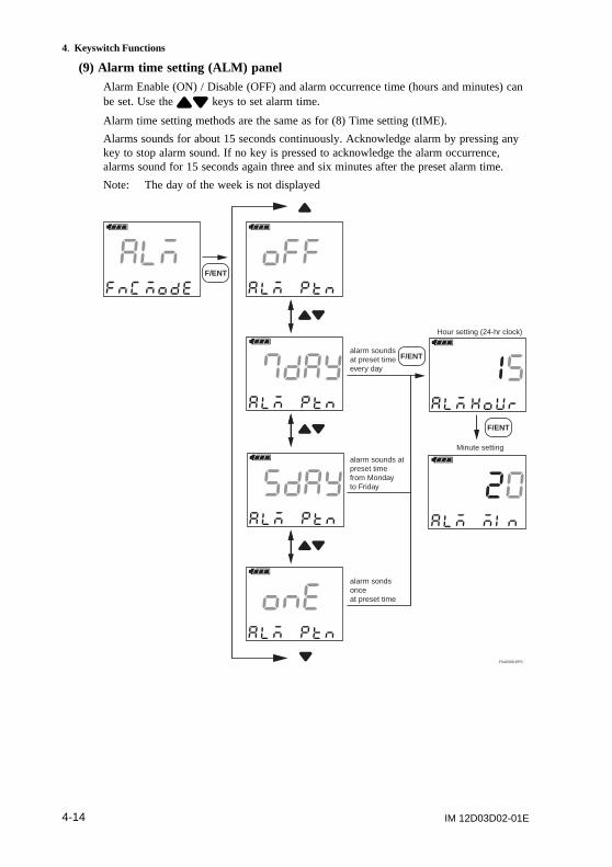
(9) Alarm time setting (ALM) panelAlarm Enable (ON) / Disable (OFF) and alarm occurrence time (hours and minutes) canbe set. Use the keys to set alarm time.
Alarm time setting methods are the same as for (8) Time setting (tIME).
Alarms sounds for about 15 seconds continuously. Acknowledge alarm by pressing anykey to stop alarm sound. If no key is pressed to acknowledge the alarm occurrence,alarms sound for 15 seconds again three and six minutes after the preset alarm time.
Note: The day of the week is not displayed
F040309.EPS
Hour setting (24-hr clock)
Minute setting
alarm sounds at preset timeevery day
alarm sounds atpreset timefrom Monday to Friday
alarm sonds once at preset time
F/ENT
F/ENT
F/ENT
IM 12D03D02-01E 4-15
4. Keyswitch Functions
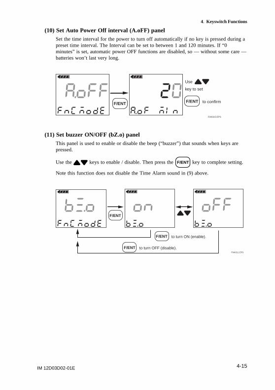
(10) Set Auto Power Off interval (A.oFF) panelSet the time interval for the power to turn off automatically if no key is pressed during apreset time interval. The Interval can be set to between 1 and 120 minutes. If “0minutes” is set, automatic power OFF functions are disabled, so — without some care —batteries won’t last very long.
F040310.EPS
F/ENT
Use
key to set
to confirmF/ENT
(11) Set buzzer ON/OFF (bZ.o) panelThis panel is used to enable or disable the beep (“buzzer”) that sounds when keys arepressed.
Use the keys to enable / disable. Then press the F/ENT key to complete setting.
Note this function does not disable the Time Alarm sound in (9) above.
F040311.EPS
F/ENT
to turn ON (enable).F/ENT
to turn OFF (disable).F/ENT
IM 12D03D02-01E4-16
4. Keyswitch Functions
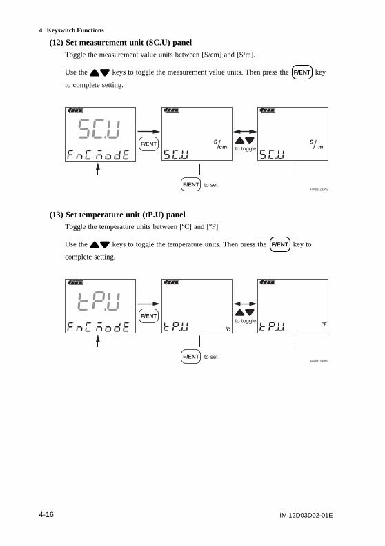
(12) Set measurement unit (SC.U) panelToggle the measurement value units between [S/cm] and [S/m].
Use the keys to toggle the measurement value units. Then press the F/ENT key
to complete setting.
F040312.EPS
to toggleF/ENT
to setF/ENT
(13) Set temperature unit (tP.U) panelToggle the temperature units between [8C] and [8F].
Use the keys to toggle the temperature units. Then press the F/ENT key to
complete setting.
F040313.EPS
to toggleF/ENT
to setF/ENT
IM 12D03D02-01E 4-17
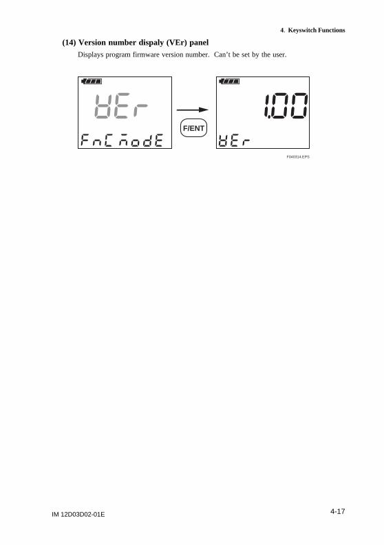
4. Keyswitch Functions
(14) Version number dispaly (VEr) panelDisplays program firmware version number. Can’t be set by the user.
F040314.EPS
F/ENT
IM 12D03D02-01E4-18
4. Keyswitch Functions
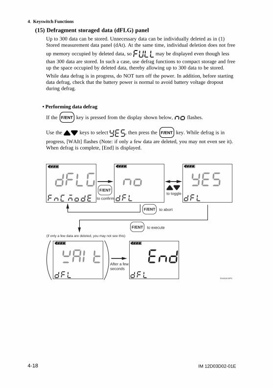
(15) Defragment storaged data (dFLG) panelUp to 300 data can be stored. Unnecessary data can be individually deleted as in (1)Stored measurement data panel (dAt). At the same time, individual deletion does not free
up memory occupied by deleted data, so may be displayed even though less
than 300 data are stored. In such a case, use defrag functions to compact storage and freeup the space occupied by deleted data, thereby allowing up to 300 data to be stored.
While data defrag is in progress, do NOT turn off the power. In addition, before startingdata defrag, check that the battery power is normal to avoid battery voltage dropoutduring defrag.
• Performing data defrag
If the F/ENT key is pressed from the display shown below, flashes.
Use the keys to select , then press the F/ENT key. While defrag is in
progress, [WAIt] flashes (Note: if only a few data are deleted, you may not even see it).When defrag is complete, [End] is displayed.
F040315.EPS
to toggleto confirm
F/ENT
to abortF/ENT
to executeF/ENT
After a few seconds
(if only a few data are deleted, you may not see this)
IM 12D03D02-01E 5-1
5. Handling of the SC72 Personal Conductivity Meter
5. Handling of the SC72 PersonalConductivity Meter
5.1 Tips to Maintain Meter PerformanceThe SC72 meter appears to be very simple, but is a precision instrument. To ensure thatmeasurement accuracy is maintained, observe the following precautions regardingpreliminary setting, measurement, maintenance and storage.
Preliminary setting, measurement, maintenance and storage:
Measurement
MaintenancePreliminary
setting
Storage
F050101.EPS
Table 5.1 Observe the following precautions
Prel iminarysett ing
Measurement
Maintenenace
Storage
T0501.EPS
Setting cell constant
• Set specific electrode cell constant.
Setting temperature coefficient
• Set liquid temperature coefficient when the standard temperature
conversion is required (see Section 2.5)
If standard temperature conversion is not requiresd, set 0.00.
• Select one of the three conductivity measurement ranges (0 to
200mS/cm, 0 to 200mS/cm, or 0 to 2S/cm) corresponding to the type of
electrode used.
Temperature measuring range is 0 to 808C.
• When measurement is completed, thoughly wash electrode to remove the
measured liquid.
• If the electrode gets stained or deformed, its cell constant may change.
In this case, calibrate the meter with standard solution (see Section 5.4).
• Avoid high-temperature, high-humidity storage locations.
IM 12D03D02-01E5-2
5. Handling of the SC72 Personal Conductivity Meter
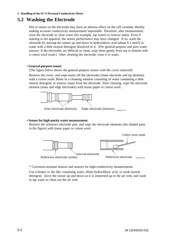
5.2 Washing the ElectrodeDirt or stains on the electrode may have an adverse effect on the cell constant, therebymaking accurate conductivity measurement impossible. Therefore, after measurement,rinse the electrode in clean water (for example, tap water) to remove stains. Even ifstaining is not apparent, the sensor performance may have changed. If so, wash theelectrode by moving the sensor up and down in hydrochloric acid (about 0.1 mol/l) orwater with a little neutral detergent dissolved in it. [For general-purpose and pure-watersensors: if the electrodes are difficult to clean, wipe them gently from top to bottom witha cotton wool swab.] After cleaning the electrode, rinse it in water.
• General-purpose sensor(The figure below shows the general-purpose sensor with the cover removed).
Remove the cover, and wipe stains off the electrodes (inner electrode and tip element)with a cotton swab. Rinse in a cleaning solution consisting of water containing a littleneutral detergent, to remove stains from the electrode. After cleaning, wipe the electrodeelement (inner and edge electrodes) with tissue paper or cotton wool.
Inner electrode (titanium) Edge electrode (titanium)F050201.EPS
• Sensor for high-purity water measurementRemove the reference electrode part, and wipe the electrode elements (the shaded partsin the figure) with tissue paper or cotton wool.
Reference electrode contactInternal electrode
Reference electrode
Cotton wool swab
F050202.EPS
* Corrosion-resistant sensors and sensors for high-conductivity measurements
Use a beaker or the like containing water, dilute hydrochloric acid, or weak neutraldetergent; move the sensor up and down so it is immersed up to the air vent, and washin tap water to clean out the air vent.
IM 12D03D02-01E 5-3
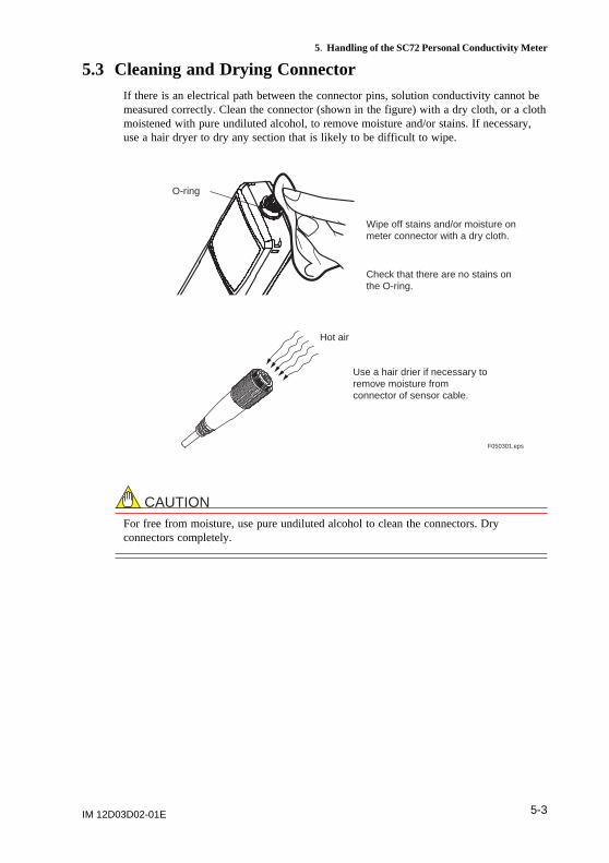
5. Handling of the SC72 Personal Conductivity Meter
5.3 Cleaning and Drying ConnectorIf there is an electrical path between the connector pins, solution conductivity cannot bemeasured correctly. Clean the connector (shown in the figure) with a dry cloth, or a clothmoistened with pure undiluted alcohol, to remove moisture and/or stains. If necessary,use a hair dryer to dry any section that is likely to be difficult to wipe.
Wipe off stains and/or moisture onmeter connector with a dry cloth.
Check that there are no stains onthe O-ring.
O-ring
Hot air
Use a hair drier if necessary toremove moisture fromconnector of sensor cable.
F050301.eps
CAUTIONFor free from moisture, use pure undiluted alcohol to clean the connectors. Dryconnectors completely.
IM 12D03D02-01E5-4
5. Handling of the SC72 Personal Conductivity Meter
5.4 Calibration with Standard SolutionNote: Calibration with standard solution means to measure a standard solution of
accurately-known conductivity and to adjust SC72 meter so that the displayedmeasured value is the same as the known conductivity value of the standardsolution.
If the sensor has been used for a long time, and does not look clean despite washing,recalibrate the SC72 meter with standard solution to check if cell constant is normal.
If “ ” occurs during calibration with standard solution, replace the sensor.
Note that if calibration with the standard solution shows that the cell constant haschanged, update the cell constant value on the sensor cable with the new data.
Notes for calibration with standard solution:
Types of standard solutionUse NaCl (sodium chloride) or KCl (potassium chloride) solutions.
(1) NaCl (sodium chloride) solutionWhen NaCl solution is used, the temperature coefficient of NaCl is built into thetemperature compensation functions of the meter so conductivity converted to 25 8C canbe readily obtained regardless of liquid temperature. Standard NaCl solution of 0.1 mol/l(normal unit expressing concentration of solution) is available as an option fromYokogawa. For more details, see Section 1.7.
When the sensor for high purity water measurement is used, dilute the standard solutionwith pure water to obtain 0.001 ml/l solution of conductivity 1 mS/cm. Conductivity is asfollows:
0.1 mol - NaCl solution: conductivity 10.67 mS/cm at 258C
0.001 mol/l - NaCl: conductivity 123.9 mS/cm at 258C
(2) KCl solutionTable 5.2 describes how to make KCl solution of different concentrations, and lists theirconductivities.
Table 5.2 How to make KCl solutions, and their conductivities(based on JIS K 0102)
KClsolution
A
B
C
D
08C
65176
7138
773.8
188C
97838
11167
1220.5
258C
111342
12856
1408.8
146.93
KCl standard solution, mS/cm
T0502.EPS
How to make
Dissolve 74.2460g of KCl in water to
get 1l at 20618C.
Dissolve 7.4365g of KCl in water to get
1l at 20618C.
Dissolve 0.7440g of KCl in water to get
1l at 20618C.
Dissolve 100ml of standard solution C
avobe in water to get 1l at 20618C.
IM 12D03D02-01E 5-5
5. Handling of the SC72 Personal Conductivity Meter
* Before calibrating the meter with standard solution, check that the electrode is clean. Ifstains are found, clean the electrode first. Also check that the cover (of general-purposesensor) and outer electrode (of sensor for high purity water measurement) are secure.Cell constant is affected by stains or loose cover.
When calibrating, ensure that measuring range is set so that you can enter conductivity toas many digits as possible. For example, in the table above, the conductivity of standardsolution C at 258C is 1408.8. If the meter is set to autorange, or to a manual range of 0to 2.000 mS/cm, you could set this as 1.409 (four digits). However if the range were setto 0 to 200.0 mS/cm, you could only enter conductivity value as 1.4 (only two digitsaccuracy, which is inadequate for calibration with standard solution.
Before calibrating the meter with standard solutionCheck and set the following items before calibrating the meter with standard solution.
(1) Check sensor for stainsCheck that there are no stains on the sensor. Also check that the meter cover (forgeneral-purpose sensor) or outer electrode (for sensor for high purity water sensor) arenot loose.
(2) Setting temperature coefficientsWhen the meter is calibrated with a NaCl solution, set a temperature coefficient(indicated by “NaCl”) for NaCl solution. When it is calibrated with a KCl standardsolution, set a temperature coefficient of 0.00 (%/8C).
(3) Standard solution temperatureFor a NaCl standard solution, check that the standard solution temperature is in the range258C 6 108C.
For a KCl standard solution, stabilize its temperature at 258C 6 18C or 188C 6 18C.
If it is difficult to maintain the above temperatures, set the temperature coefficient of KClstandard solution in the meter. To find the temperature coefficient, refer to table 5.2above and to Section 7.3, “Temperature Compensation and Finding TemperatureCompensation Coefficient.”
IM 12D03D02-01E5-6
5. Handling of the SC72 Personal Conductivity Meter
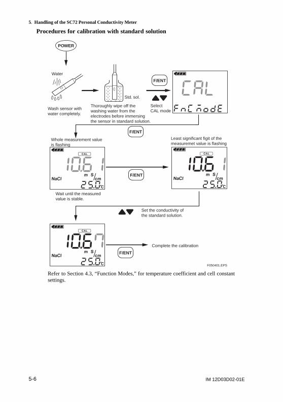
Procedures for calibration with standard solution
F050401.EPS
Whole measurement value is flashing
Complete the calibration
Least significant figit of the measuremet value is flashing
Select CAL mode
POWER
F/ENT
F/ENT
F/ENT
F/ENT
Std. sol.
Water
Wash sensor with water completely.
Wait until the measured value is stable.
Set the conductivity of the standard solution.
Thoroughly wipe off the washing water from the electrodes before immersing the sensor in standard solution.
Refer to Section 4.3, “Function Modes,” for temperature coefficient and cell constantsettings.
IM 12D03D02-01E 5-7
5. Handling of the SC72 Personal Conductivity Meter
5.5 Storage and Maintenance
• Method of storageCare is required when storing the SC72 meter. To maintain the SC72 meter in goodcondition, observe the following:
(1) After measurement, thoroughly wash the sensor in water.
(2) Leave the sensor connected to the meter body, to protect the connector fromstaining. Connector contamination could affect connector leakage resistance andthus conductivity reading accuracy, or affect the waterproofing afforded by the O-ring.
(3) Do not place any object on top of the sensor or on the top of SC72 meter.
• Storage locationWhen the SC72 meter is not being used, store it in a safe place. If it is to be stored for along time, store it:
* In a dry place (low humidity) at normal temperatures.
* Out of direct sunshine.
* Do not store it in a corrosive gas atmosphere.
* In a location free from water condensation.
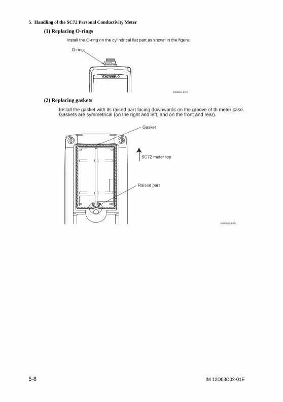
• Replacing O-rings or gasketsGaskets for the battery box and O-rings for sensor connections can be replaced. If theyare very dirty or damaged, replace them with new ones.
CAUTIONWhen installing O-rings and gaskets, clean them and their mounting surface with a clothmoistened with alcohol so that they are free from dirt. Otherwise, water resistance maynot be assured.
IM 12D03D02-01E5-8
5. Handling of the SC72 Personal Conductivity Meter
(1) Replacing O-rings
O-ring
Install the O-ring on the cylindrical flat part as shown in the figure.
F050501.EPS
(2) Replacing gaskets
Gasket
Raised part
SC72 meter top
Install the gasket with its raised part facing downwards on the groove of th meter case.Gaskets are symmetrical (on the right and left, and on the front and rear).
F050502.EPS
IM 12D03D02-01E 6-1
6. Troubleshooting
6. Troubleshooting
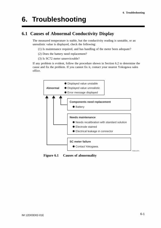
6.1 Causes of Abnormal Conductivity DisplayThe measured temperature is stable, but the conductivity reading is unstable, or anunrealistic value is displayed, check the following:
(1) Is maintenance required, and has handling of the meter been adequate?
(2) Does the battery need replacement?
(3) Is SC72 meter unserviceable?
If any problem is evident, follow the procedure shown in Section 6.2 to determine thecause and fix the problem. If you cannot fix it, contact your nearest Yokogawa salesoffice.
Abnormal
Components need replacement
d Displayed value unstable
d Displayed value unrealistic
d Error message displayed
d Battery
Needs maintenance
d Needs recalibration with standard solution
d Electrode stained
d Electrical leakage in connector
SC meter failure
d Contact Yokogawa.F0601.EPS
Figure 6.1 Causes of abnormality
IM 12D03D02-01E6-2
6. Troubleshooting
6.2 Error Messages and Corrective Action
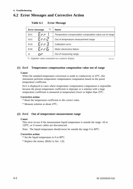
Table 6.1 Error Message
T0601.EPS
Error message
Err1
Err2
Err3
Err6
or
Name
Temperature compensation computation value out of range
Out of temperature measurement range
Calibration error
Meter electronics failure
Out of measuring range
*1 Alphabet values simulated on a numeric display
*1
(1) Err1 Temperature compensation computation value out of range
Cause:When the standard temperature conversion is made to conductivity at 258C, thisinstrument performs temperature compensation computation based on the presettemperature coefficient.
Err1 is displayed in cases where temperature compensation computation is impossiblebecause the preset temperature coefficient is improper or a solution with a largetemperature coefficient is measured at temperatures lower or higher than 258C.
Corrective action:* Reset the temperature coefficient to the correct value.
* Measure solution at about 258C.
(2) Err2 Out of temperature measurement range
Cause:This error occurs if the measurement liquid temperature is outside the range -10 to1208C, or if sensor cables are disconnected.
Note: The liquid temperature should never be outside the range 0 to 808C.
Corrective action:* Set the liquid temperature to 0 to 808C.
* Replace the sensor. (Refer to Sec. 1.6)
IM 12D03D02-01E 6-3
6. Troubleshooting
(3) Err3 Calibration error
Cause:When the calibration with standard solution is made, each time cell constants arechanged. Err3 occurs if the conductivity of the standard solution is wrong, or changedcell constants are beyond 6 20% of the standard cell constant, due to a damaged sensor.
Corrective action:* Use correct standard solution conductivity. (Refer to Sec. 5.4)
* Replace the sensor. (Refer to Sec. 1.6)
(4) Err6 Meter electronics failure
Cause:Err6 occurs if the meter electronics fails.
Corrective action:* Contact your nearest Yokogawa sales office.
(5) or Out of measurement range
Cause:Conductivity is over the maximum value on the range.
Corrective action:For manual ranging, select an appropriate range. If value exceeds maximum of highestrange (or when on autorange), use a more appropriate sensor (see Sec. 4.3 (3)).
IM 12D03D02-01E6-4
6. Troubleshooting
6.3 Causes of Abnormal Measured ValueIf error messages do not occur, but measured values seem incorrect, check the following:
* Are cell constants and temperature coefficients correctly set?
* Is the sensor properly connected to the meter?
* Are bubbles attached to the electrode portion?
* Is the sensor damaged or dirty?
6.4 Other conditions
• An alarm soundsThe alarm clock is set (see Sec. 4.3 (9) and change setting as required).
• To Enable / Disable Key-Press Audible Feedback (buzzer)Refer to Sec. 4.3 (11) to change setting as required.
IM 12D03D02-01E 7-1
7. Measuring Principles of this Instrument
7. Measuring Principles of thisInstrument
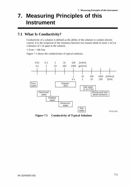
7.1 What Is Conductivity?Conductivity of a solution is defined as the ability of the solution to conduct electriccurrent. It is the reciprocal of the resistance between two sensors (both of areas 1 m2) ata distance of 1 m apart in the solution.
1 S/cm = 100 S/m
Figure 7.1 shows the conductivities of typical solutions.
Pure water
Sea water
Deionized water
Distilled water
Reservoir water
Strong acid and alkali solutions
Salt water (1 to 27%)
Organic acid
0.1 1 10 100 1000 [mS/cm]
0.01 0.1 1 10 100 [mS/m]
1 10 100 1000 [mS/cm]0.1 1 10 100 [S/m]
F0701.EPS
Figure 7.1 Conductivity of Typical Solutions
IM 12D03D02-01E7-2
7. Measuring Principles of this Instrument
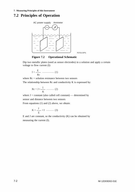
7.2 Principles of Operation
F0702.EPS
AC power supply Ammeter
Figure 7.2 Operational Schematic
Dip two metallic plates (used as sensor electrodes) in a solution and apply a certainvoltage to flow current (I):
I = (1)E
Rcwhere Rc = solution resistance between two sensors
The relationship between Rc and conductivity K is expressed by:
Rc = J • (2)1
Kwhere J = constant (also called cell constant) — determined by
sensor and distance between two sensors
From equations (1) and (2) above, we obtain:
K = • I (3)J
EE and J are constant, so the conductivity (K) can be obtained by
measuring the current (I).
IM 12D03D02-01E 7-3
7. Measuring Principles of this Instrument
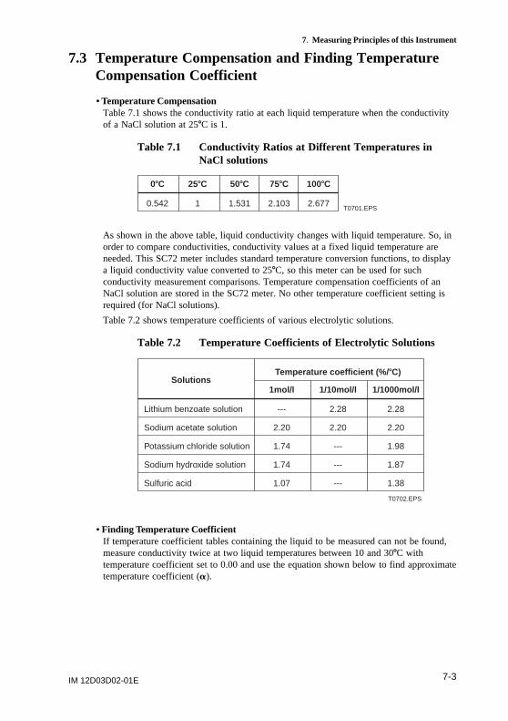
7.3 Temperature Compensation and Finding TemperatureCompensation Coefficient
• Temperature CompensationTable 7.1 shows the conductivity ratio at each liquid temperature when the conductivityof a NaCl solution at 258C is 1.
Table 7.1 Conductivity Ratios at Different Temperatures inNaCl solutions
T0701.EPS0.542 1 1.531
08C 258C 508C
2.103
758C
2.677
1008C
As shown in the above table, liquid conductivity changes with liquid temperature. So, inorder to compare conductivities, conductivity values at a fixed liquid temperature areneeded. This SC72 meter includes standard temperature conversion functions, to displaya liquid conductivity value converted to 258C, so this meter can be used for suchconductivity measurement comparisons. Temperature compensation coefficients of anNaCl solution are stored in the SC72 meter. No other temperature coefficient setting isrequired (for NaCl solutions).
Table 7.2 shows temperature coefficients of various electrolytic solutions.
Table 7.2 Temperature Coefficients of Electrolytic Solutions
T0702.EPS
Solutions
Lithium benzoate solution
Sodium acetate solution
Potassium chloride solution
Sodium hydroxide solution
Sulfuric acid
---
2.20
1.74
1.74
1.07
2.28
2.20
---
---
---
2.28
2.20
1.98
1.87
1.38
Temperature coefficient (%/8C)
1mol/l 1/10mol/l 1/1000mol/l
• Finding Temperature CoefficientIf temperature coefficient tables containing the liquid to be measured can not be found,measure conductivity twice at two liquid temperatures between 10 and 308C withtemperature coefficient set to 0.00 and use the equation shown below to find approximatetemperature coefficient (a).
IM 12D03D02-01E7-4
7. Measuring Principles of this Instrument
a = Temp. coef. 3 100 (%/8C)K 2 K
K ( t 2 25 ) 2 K ( t 2 25 ) 1
1 2
1 1
2 2
2 2 1
2 1
where t , t : liquid temperature (8C)K : conductivity at tK : conductivity at t
(Calculation example)
To find the temperature coefficient of liquid with conductivity - 124.5 (S/cm at liquidtemperature 18.08C and 147.6 (S/cm at liquid temperature 31.08C, substitute t1 = 18.0,t2 = 31.0, K1 = 124.5, K2 = 147.6 in the equation above, thus we can obtain:
a = 3 100147.6 2 124.5
124.53(31.0225)2147.6 3(18.0225)
= 3 10023.1
747.02(21033.2)
= 1.298
Set the temperature coefficient 1.30 in the SC72 meter (as meter allows three digits to beentered).
• Checking if meter is working correctlyWhen the temperature coefficient already set is accurate, the conductivity displayedshould be constant regardless of liquid temperature (within permitted temperature range).Check that the temperature coefficient already set is accurate. When the liquidtemperature is lowered, if a larger conductivity is indicated, the temperature coefficientalready set is too small; whereas, if a smaller conductivity is indicated, the temperaturecoefficient already set is too large. In such a case, change the temperature coefficientsuch that the measured conductivity does not change with temperature.
7.4 Wetted Part Materials of Sensors
• For general-purpose sensorTitanium (sensor)
Polyphenylene sulfite resin, Polypropylene resin (insulated area and cover)
Fluoro rubber (O-ring)
• Sensor for high purity water measurementSUS 316 stainless steel (electrode element)
Polypropylene resin (insulated area)
Fluoro rubber (O-ring)
• Chemical-resistant sensorGlass, platinum black (electrode element)
Sensor for high-conductivity measurementGlass, platinum black (electrode element)
IM 12D03D02-01E 1
Appendix
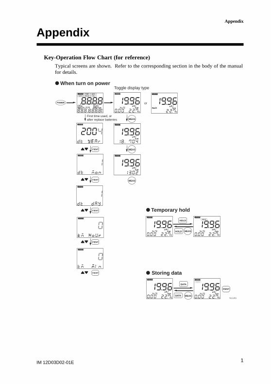
Appendix
Key-Operation Flow Chart (for reference)Typical screens are shown. Refer to the corresponding section in the body of the manualfor details.
T01.EPS
POWER
F/ENT
F/ENT
F/ENT
F/ENT
F/ENT
d When turn on power
First time used, orafter replace batteries MEAS
MEAS
MEAS
Toggle display type
or
HOLD
HOLD
MEAS
d Temporar y hold
F/ENT
MEAS
DATA
DATA
d Storing data
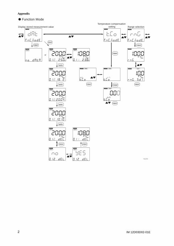
IM 12D03D02-01E2
Appendix
F/ENT
T02.EPS
F/ENTF/ENT
DATA
DATA
DATA
DATA
F/ENT
d Function Mode
or
Display stored measurement value
F/ENT
F/ENT
F/ENT
F/ENT
Temperature compensation setting
F/ENT
F/ENT
Range selection
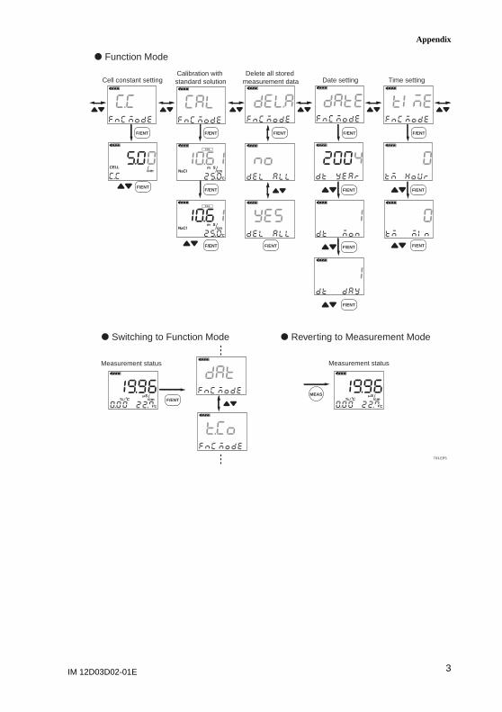
IM 12D03D02-01E 3
Appendix
F/ENT
F/ENT
T03.EPS
d Function Mode
Cell constant setting
F/ENT
F/ENT
F/ENT
Calibration with standard solution
F/ENT
F/ENT
Delete all stored measurement data
F/ENT
F/ENT
F/ENT
F/ENT
Date setting
F/ENT
F/ENT
F/ENT
Time setting
d Switching to Function Mode d Reverting to Measurement Mode
Measurement status Measurement status
F/ENTMEAS
IM 12D03D02-01E4
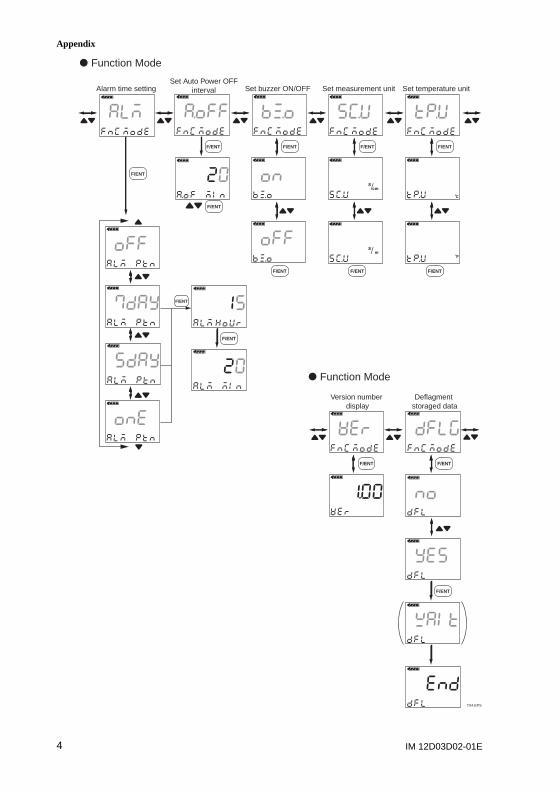
Appendix
F/ENT
F/ENT
F/ENT
d Function Mode
d Function Mode
Alarm time setting
F/ENT
F/ENT
Set Auto Power OFFinterval
F/ENT
F/ENT
Set buzzer ON/OFF
F/ENT
F/ENT
Set measurement unit
F/ENT
F/ENT
Set temperature unit
F/ENT
Version number display
F/ENT
F/ENT
T04.EPS
Deflagment storaged data
Revision Record
Manual Title : Model SC72 Personal Conductivity Meter
Manual Number : IM 12D03D02-01E
Edition Date Remark (s)
1st Aug. 2004 Newly published
2nd Apr. 2008 Addition of information on EMC compliance: P.1-3
Addition of CAUTION: P2-2
Correction: P.1, 1-2, 1-6, 2-1, 2-3, 3-1, 3-3, 4-1. 4-5,
App-1, App-4
3rd Aug. 2009 Change of information on EMC compliance: P.1-3
User'sManual
Model SC72Personal Conductivity Meter
© Copyright 2009. 9th Edition : Feb., 2016 (YK) IM 12D03D02-01E
3rd Edition
Thank you for selecting our Model SC72 Personal Conductivity Meter.There is a part of correction in User's Manual, IM 12D03D02-01E, 3rd Edition, supplied with the product.Please correct as follows in your copy.
Note• p. 1 The related documents (User's Manual) are as follows.
IM 12D03D02-01E Model SC72 Personal Conductivity Meter (this manual) IM 12D03D02-02E Model SC72 Personal Conductivity Meter Quick Manual * the “E” in the document number is the language code.
• p. 3 Preface, Some revision of "Warranty and Service", addition of "How to replace and dispose the batteries."
• p. 1-4 Deletion of instrument sheet and addition code -NB. In South Korea and Malaysia, primary battery is limited by regulations. Please use batteries with the authorized certification mark for each country.
• p. 1-8 Some revision of section 1.7 "Options."• p. 1-3
EMC Regulatory Arrangement in Australia and New Zealand (RCM) EN 55011 Class B, Group 1 Korea Electromagnetic Conformity Standard Class B 한국 전자파적합성 기준
B급 기기 (가정용 방송통신기자재) 이 기기는 가정용(B급) 전자파적합기기로서 주로 가정에서 사용하는 것을 목적으로 하며, 모든 지역에서 사용할 수 있습니다.
Environmental resistance: Compliant with RoHS *, WEEE, and EU battery directive*: RoHS conformity is after style S2.
• How to dispose this product (This directive is valid only in the EU.)This product complies with the WEEE Directive marking requirement.This marking indicates that you must not discard this electrical/electronic product in domestic household waste.Product CategoryWith reference to the equipment types in the WEEE directive Annex I, this product is classified as a “Monitoring and Control instruments” product.Do not dispose in domestic household waste. When disposing products in the EU, contact your local Yokogawa Europe B. V. office.
• Authorized Representative in EEAThe Authorized Representative for this product in EEA is Yokogawa Europe B.V. (Euroweg 2, 3825 HD Amersfoort, The Netherlands).
Supplement
IM 12D03D02-01E 3
Preface
Warranty and Service
Yokogawa products and parts are guaranteed to be free from defects in workmanship andmaterials under normal use and service for a period of (typically) 12 months from thedate of shipment from the manufacturer.
Individual sales units may offer different warranty periods, so the original purchase ordershould be consulted for the conditions of sale. Damage caused by normal wear and tear,inadequate maintenance, corrosion, or due to chemical processes, is excluded from thiswarranty coverage. In addition, performance deterioration of the sensor caused by theoperating environment mentioned above is not considered to be a defect. Yokogawacannot carry out repairs in such a case so please replace the sensor.
In the event of a warranty claim, any items that are considered to be defective should besent (freight paid) for repair or replacement (at Yokogawa discretion) to the servicedepartment of the relevant sales unit. The following information must be included in aletter accompanying the returned items:
Model code and serial number
Copy of original purchase order showing the date
Length of time used, and the measuring environment
Fault symptoms, and circumstances of failure
Statement whether service under warranty or out-of-warranty service is requested
Complete shipping and billing instructions for return of goods, plus the name andphone number of a contact person who can be reached for further information
Goods that have been in contact with process fluids must be decontaminated / disinfectedbefore shipment, and a statement to this effect should be included. Safety data sheets forall process components that the goods have exposed to should also be included.
How to replace and dispose the batteries:
This is an explanation about the new EU Battery Directive (DIRECTIVE 2006/66/EC).This directive is only valid in the EU.
Batteries are included in this product.
When you remove batteries from this product and dispose them, discard them inaccordance with domestic law concerning disposal.
Take a right action on waste batteries, because the collection system in the EU on wastebatteries are regulated.
Battery type: Alcaline dry cell
Notice:
The symbol (see above), which is marked on the batteries, means they shall be sorted outand collected as ordained in ANNEX II in DIRECTIVE 2006/66/EC.
How to remove batteries safely: Refer to subsection "2.1 Installing the Batteries".
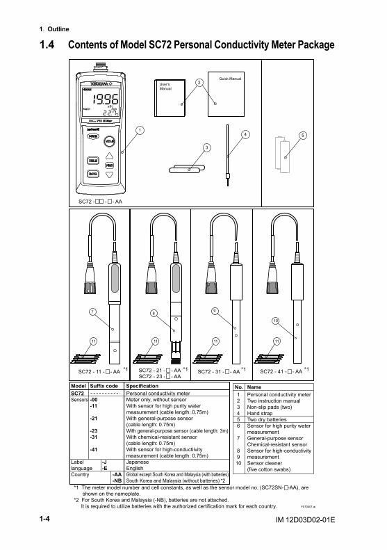
IM 12D03D02-01E1-4
1. Outline
1.4 Contents of Model SC72 Personal Conductivity Meter Package
11 11 11 11
7 89
10
154
3
2Quick Manual
User'sManual
SC72 - - - AA
SC72 - 11 - - AA SC72 - 31 - - AA SC72 - 41 - - AA*1 *1 *1 *1
*1 The meter model number and cell constants, as well as the sensor model no. (SC72SN- -AA), are shown on the nameplate.*2 For South Korea and Malaysia (-NB), batteries are not attached. It is required to utilize batteries with the authorized certification mark for each country.
SC72 - 21 - - AASC72 - 23 - - AA
SC72Sensors -00 -11
-21
-23 -31
-41
Label -Jlanguage -ECountry -AA -NB
Specification123456
7
89
10
No.Personal conductivity meterTwo instruction manualNon-slip pads (two)Hand strapTwo dry batteriesSensor for high purity water measurementGeneral-purpose sensorChemical-resistant sensorSensor for high-conductivity measurementSensor cleaner (five cotton swabs)
NameModel Suffix codePersonal conductivity meterMeter only, without sensorWith sensor for high purity water measurement (cable length: 0.75m)With general-purpose sensor (cable length: 0.75m)With general-purpose sensor (cable length: 3m)With chemical-resistant sensor (cable length: 0.75m)With sensor for high-conductiivity measurement (cable length: 0.75m)JapaneseEnglishGlobal except South Korea and Malaysia (with batteries)South Korea and Malaysia (without batteries) *2
F010401.ai
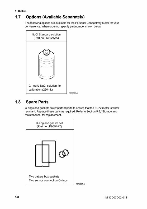
IM 12D03D02-01E1-8
1. Outline
1.7 Options (Available Separately)The following options are available for the Personal Conductivity Meter for your convenience. When ordering, specify part number shown below.
NaCl Standard solution(Part no.: K9221ZA)
0.1mol/L NaCl solution for calibration (250mL)
F010701.ai
1.8 Spare PartsO-rings and gaskets are important parts to ensure that the SC72 meter is water resistant. Replace these parts as required. Refer to Section 5.5, “Storage and Maintenance” for replacement.
O-ring and gasket set(Part no.: K9654AY)
Two battery box gasketsTwo sensor connection O-rings
F010801.ai


![User’s - Yokogawa Electric s Manual Yokogawa Electric Corporation IM 21B3C1-01E VP200 Current-to-Pneumatic Positioner [Style : S3] IM 21B3C1-01E 7th Edition IM 21B3C1-01E i INTRODUCTION](https://img.pdfslide.us/doc/110x75/5abb71277f8b9a441d8cd2f8/users-yokogawa-electric-s-manual-yokogawa-electric-corporation-im-21b3c1-01e.jpg)