Embed Size (px)
Citation preview

1
TYPE 95IR/95UV/95DSMODEL S1, S2
Integrated Flame Scannerwith Internal Flame Relay
RoHS Compliant to EU Directive 2002/95/EC
TUVSIL2
DESCRIPTIONThe FIREYE InSight Type 95IR, 95UV, and 95DS flame scanners are micro-processor based flamescanners utilizing solid state infrared (IR) or ultraviolet (UV) or dual (IR and UV) sensors.
The FIREYE InSight Type 95 flame scanners incorporate an internal flame relay with adjustableON/OFF thresholds, thereby eliminating the need for a remote flame amplifier.
The InSight scanners are now a replacement to the FIREYE Type 45FS1 and 45UVFS1 SignatureScanners™ as well as the Type 45RM4 to detect the presence or absence of a target flame in singleor multi-burner applications.
The InSight scanners measure the amplitude of the modulations (the flame “flicker”) that occurwithin the targeted flame. During the scanner set-up procedure, the modulation frequency that yieldsthe best flame ON/OFF discrimination is selected. The appropriate modulation frequency and sensorgain is either manually selected (S1 models), or automatically selected with manual override capa-bility (S2 models).
The InSight 95IR, 95UV, and 95DS scanners are each available in two models differentiated by fea-ture levels.
The Standard Model S1 has three choices of modulation frequency, adjustable sensor gain, adjust-able flame relay ON/OFF thresholds, 4-20 mA analog signal strength output, fault relay, and twoselectable programmable files to store setpoints (for two different fuels or firing rates).
The Expanded Model S2 adds automatic programming (AutoTune) with manual override capability,21 choices of flame flicker frequency, a total of four selectable programmable files to store setpoints,plus adds remote communication capability via Fireye Windows 95/98/NT user software.
All FIREYE InSight scanner models are powered by 24 Vdc and contain electronic self-checking(no mechanical shutter required). The scanners contain an eight character alpha-numeric LED dis-play and a four (4) push-button keypad to enable the user to view operating parameters and selectsetpoints.
“CG” models include a 10 ft. (3m) captive cable and gland. Non-“CG” models have a twelve-pinelectrical quick-disconnect. Fiber optic-mount versions of the InSight scanners are also available.Refer to bulletin CU-101 for installation instructions.
CU-95NOVEMBER 9, 2016
2
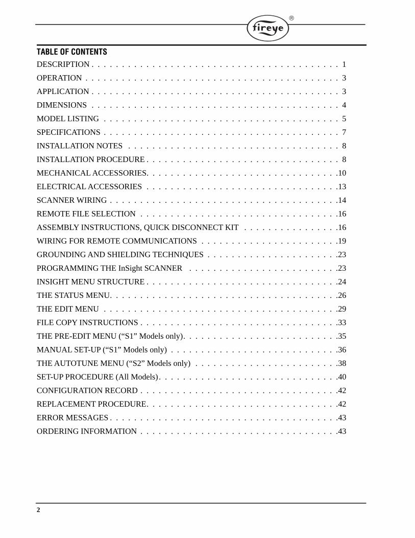
TABLE OF CONTENTSDESCRIPTION . . . . . . . . . . . . . . . . . . . . . . . . . . . . . . . . . . . . . . . . . 1
OPERATION . . . . . . . . . . . . . . . . . . . . . . . . . . . . . . . . . . . . . . . . . . 3
APPLICATION . . . . . . . . . . . . . . . . . . . . . . . . . . . . . . . . . . . . . . . . . 3
DIMENSIONS . . . . . . . . . . . . . . . . . . . . . . . . . . . . . . . . . . . . . . . . . 4
MODEL LISTING . . . . . . . . . . . . . . . . . . . . . . . . . . . . . . . . . . . . . . . 5
SPECIFICATIONS . . . . . . . . . . . . . . . . . . . . . . . . . . . . . . . . . . . . . . . 7
INSTALLATION NOTES . . . . . . . . . . . . . . . . . . . . . . . . . . . . . . . . . . . 8
INSTALLATION PROCEDURE . . . . . . . . . . . . . . . . . . . . . . . . . . . . . . . . 8
MECHANICAL ACCESSORIES. . . . . . . . . . . . . . . . . . . . . . . . . . . . . . . .10
ELECTRICAL ACCESSORIES . . . . . . . . . . . . . . . . . . . . . . . . . . . . . . . .13
SCANNER WIRING . . . . . . . . . . . . . . . . . . . . . . . . . . . . . . . . . . . . . .14
REMOTE FILE SELECTION . . . . . . . . . . . . . . . . . . . . . . . . . . . . . . . . .16
ASSEMBLY INSTRUCTIONS, QUICK DISCONNECT KIT . . . . . . . . . . . . . . . .16
WIRING FOR REMOTE COMMUNICATIONS . . . . . . . . . . . . . . . . . . . . . . .19
GROUNDING AND SHIELDING TECHNIQUES . . . . . . . . . . . . . . . . . . . . . .23
PROGRAMMING THE InSight SCANNER . . . . . . . . . . . . . . . . . . . . . . . . .23
INSIGHT MENU STRUCTURE . . . . . . . . . . . . . . . . . . . . . . . . . . . . . . . .24
THE STATUS MENU. . . . . . . . . . . . . . . . . . . . . . . . . . . . . . . . . . . . . .26
THE EDIT MENU . . . . . . . . . . . . . . . . . . . . . . . . . . . . . . . . . . . . . . .29
FILE COPY INSTRUCTIONS . . . . . . . . . . . . . . . . . . . . . . . . . . . . . . . . .33
THE PRE-EDIT MENU (“S1” Models only). . . . . . . . . . . . . . . . . . . . . . . . . .35
MANUAL SET-UP (“S1” Models only) . . . . . . . . . . . . . . . . . . . . . . . . . . . .36
THE AUTOTUNE MENU (“S2” Models only) . . . . . . . . . . . . . . . . . . . . . . . .38
SET-UP PROCEDURE (All Models) . . . . . . . . . . . . . . . . . . . . . . . . . . . . . .40
CONFIGURATION RECORD . . . . . . . . . . . . . . . . . . . . . . . . . . . . . . . . .42
REPLACEMENT PROCEDURE. . . . . . . . . . . . . . . . . . . . . . . . . . . . . . . .42
ERROR MESSAGES . . . . . . . . . . . . . . . . . . . . . . . . . . . . . . . . . . . . . .43
ORDERING INFORMATION . . . . . . . . . . . . . . . . . . . . . . . . . . . . . . . . .43
3
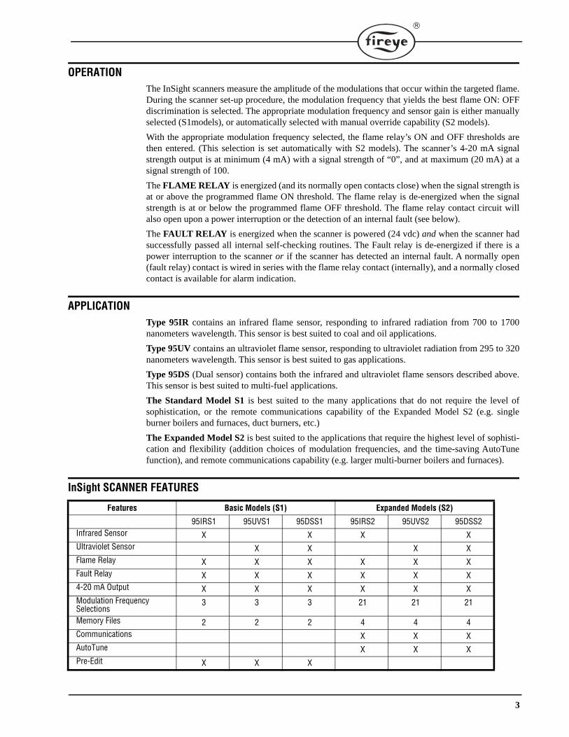
OPERATIONThe InSight scanners measure the amplitude of the modulations that occur within the targeted flame.During the scanner set-up procedure, the modulation frequency that yields the best flame ON: OFFdiscrimination is selected. The appropriate modulation frequency and sensor gain is either manuallyselected (S1models), or automatically selected with manual override capability (S2 models).
With the appropriate modulation frequency selected, the flame relay’s ON and OFF thresholds arethen entered. (This selection is set automatically with S2 models). The scanner’s 4-20 mA signalstrength output is at minimum (4 mA) with a signal strength of “0”, and at maximum (20 mA) at asignal strength of 100.
The FLAME RELAY is energized (and its normally open contacts close) when the signal strength isat or above the programmed flame ON threshold. The flame relay is de-energized when the signalstrength is at or below the programmed flame OFF threshold. The flame relay contact circuit willalso open upon a power interruption or the detection of an internal fault (see below).
The FAULT RELAY is energized when the scanner is powered (24 vdc) and when the scanner hadsuccessfully passed all internal self-checking routines. The Fault relay is de-energized if there is apower interruption to the scanner or if the scanner has detected an internal fault. A normally open(fault relay) contact is wired in series with the flame relay contact (internally), and a normally closedcontact is available for alarm indication.
APPLICATIONType 95IR contains an infrared flame sensor, responding to infrared radiation from 700 to 1700nanometers wavelength. This sensor is best suited to coal and oil applications.
Type 95UV contains an ultraviolet flame sensor, responding to ultraviolet radiation from 295 to 320nanometers wavelength. This sensor is best suited to gas applications.
Type 95DS (Dual sensor) contains both the infrared and ultraviolet flame sensors described above.This sensor is best suited to multi-fuel applications.
The Standard Model S1 is best suited to the many applications that do not require the level ofsophistication, or the remote communications capability of the Expanded Model S2 (e.g. singleburner boilers and furnaces, duct burners, etc.)
The Expanded Model S2 is best suited to the applications that require the highest level of sophisti-cation and flexibility (addition choices of modulation frequencies, and the time-saving AutoTunefunction), and remote communications capability (e.g. larger multi-burner boilers and furnaces).
InSight SCANNER FEATURES
Features Basic Models (S1) Expanded Models (S2)
95IRS1 95UVS1 95DSS1 95IRS2 95UVS2 95DSS2Infrared Sensor X X X XUltraviolet Sensor X X X XFlame Relay X X X X X XFault Relay X X X X X X4-20 mA Output X X X X X X Modulation Frequency Selections
3 3 3 21 21 21
Memory Files 2 2 2 4 4 4Communications X X XAutoTune X X XPre-Edit X X X

4
DIMENSIONSFIGURE 1. TYPE 95IR/95UV/95DS SCANNER, with ELECTRICAL QUICK-DISCONNECT (mounting flange ordered
separately)
FIGURE 2. TYPE 95IR/95UV/95DS SCANNER, “CG” MODEL with 10 FT CABLE (mounting flange ordered separately)
FIGURE 3. INSIGHT SCANNER in CENELEC HAZARDOUS AREA HOUSING (mounting flange kit ordered separately)
4.25"(107.95)
4.62"(117.35)
10.89"(276.68)
1.72"(43.74)
75°
PURGE AIR CONNECTION3/8" NPT or3/8" BSP
HOUSING MATERIAL: CAST ALUMINUM (A356)FINISH: GREY POLYESTER POWDER COAT
1 23/32" HEX(43.68)1" NPT OR
1" BSP SIGHTPIPE CONNECTION
12 - PIN ELECTRICAL CONNECTOR
LOCKING RING
MOUNTING FLANGE
4.25"(107.95)
4.62"(117.35)
11.30"(287.02)
1.72"(43.74)
75°
PURGE AIR CONNECTION3/8" NPT or3/8" BSP
HOUSING MATERIAL: CAST ALUMINUM (A356)FINISH: GREY POLYESTER POWDER COAT
1 23/32"(43.68)
1" NPT OR1" BSP SIGHTPIPE CONNECTION
LOCKING RING
MOUNTING FLANGE
14.05"(356.87)
CABLE GLAND WITH 10 FT (3 METER) CABLE
MOUNTING FLANGE
HEX
FOR WIRING INSTRUCTIONS REFER TO FIGURE 18
*HOUSING FLANGE KIT, ORDERED SEPARATELY(INCLUDES NPT OR BSP FLANGE, GASKET, MOUNTING SCREWS) P/N 129-168-1 (NPT)P/N 129-168-2 (BSP)
DIMENSIONS IN INCHES (MM)ASSEMBLY SHOWN WITH HOUSING FLANGE KIT, ORDERED SEPARATELY
3/4" NPT THREADED OPENING FOR CABLE ENTRY
MOUNTING SCREWS (4 PLC.)
3/8" THREADED OPENING FOR COOLING AIR
1" FEMALE THREADSIGHT PIPE MOUNT
VIEWING WINDOW
*HOUSING FLANGE KIT
FLANGE GASKET
0.35" (9)
4.41"(112)
5.28"(134)
8.94" (227)
4.53" (115) 4.41" (112)
3.56" (90)
5
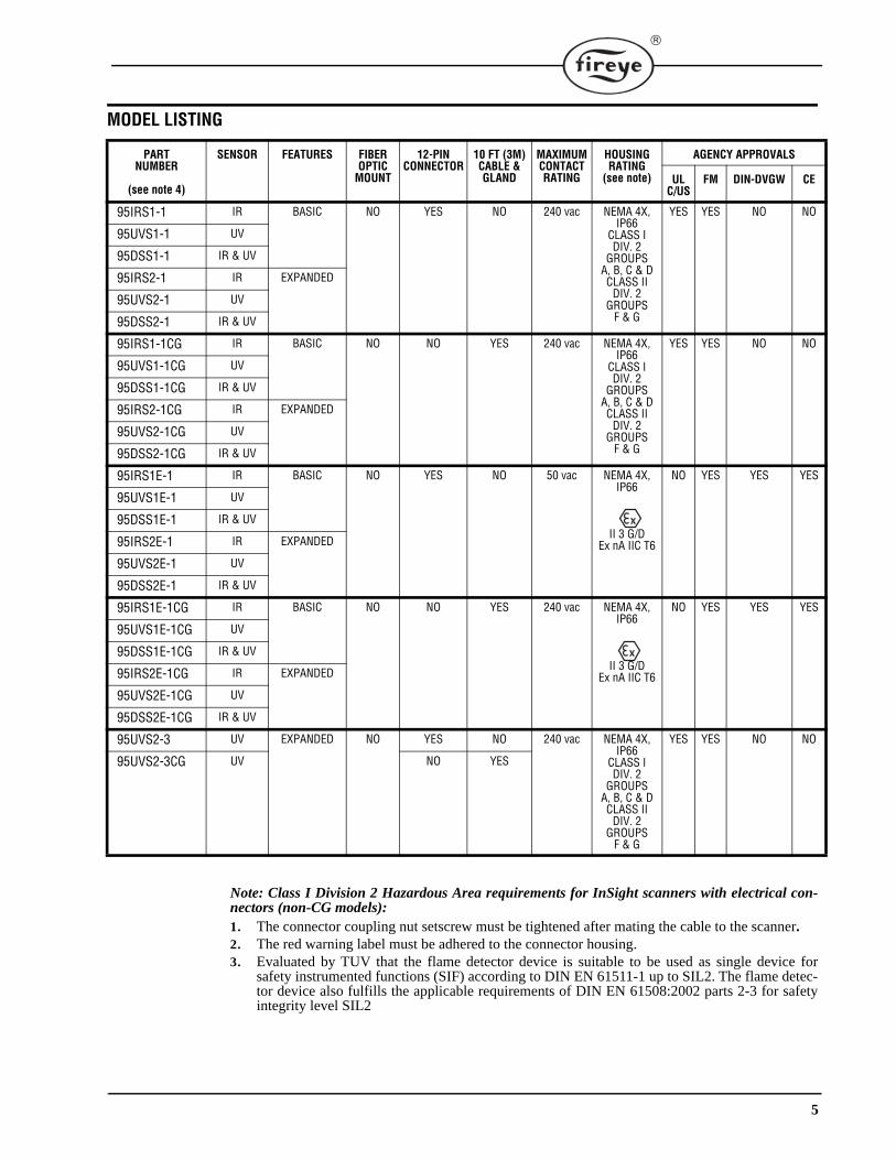
MODEL LISTING
Note: Class I Division 2 Hazardous Area requirements for InSight scanners with electrical con-nectors (non-CG models):1. The connector coupling nut setscrew must be tightened after mating the cable to the scanner.2. The red warning label must be adhered to the connector housing.3. Evaluated by TUV that the flame detector device is suitable to be used as single device for
safety instrumented functions (SIF) according to DIN EN 61511-1 up to SIL2. The flame detec-tor device also fulfills the applicable requirements of DIN EN 61508:2002 parts 2-3 for safetyintegrity level SIL2
PART NUMBER
(see note 4)
SENSOR FEATURES FIBEROPTIC
MOUNT
12-PINCONNECTOR
10 FT (3M)CABLE & GLAND
MAXIMUM CONTACT RATING
HOUSING RATING
(see note)
AGENCY APPROVALS
ULC/US
FM DIN-DVGW CE
95IRS1-1 IR BASIC NO YES NO 240 vac NEMA 4X, IP66
CLASS I DIV. 2
GROUPS A, B, C & DCLASS II
DIV. 2GROUPS
F & G
YES YES NO NO
95UVS1-1 UV
95DSS1-1 IR & UV
95IRS2-1 IR EXPANDED
95UVS2-1 UV
95DSS2-1 IR & UV
95IRS1-1CG IR BASIC NO NO YES 240 vac NEMA 4X, IP66
CLASS I DIV. 2
GROUPS A, B, C & DCLASS II
DIV. 2GROUPS
F & G
YES YES NO NO
95UVS1-1CG UV
95DSS1-1CG IR & UV
95IRS2-1CG IR EXPANDED
95UVS2-1CG UV
95DSS2-1CG IR & UV
95IRS1E-1 IR BASIC NO YES NO 50 vac NEMA 4X, IP66
II 3 G/DEx nA IIC T6
NO YES YES YES
95UVS1E-1 UV
95DSS1E-1 IR & UV
95IRS2E-1 IR EXPANDED
95UVS2E-1 UV
95DSS2E-1 IR & UV
95IRS1E-1CG IR BASIC NO NO YES 240 vac NEMA 4X, IP66
II 3 G/DEx nA IIC T6
NO YES YES YES
95UVS1E-1CG UV
95DSS1E-1CG IR & UV
95IRS2E-1CG IR EXPANDED
95UVS2E-1CG UV
95DSS2E-1CG IR & UV
95UVS2-3 UV EXPANDED NO YES NO 240 vac NEMA 4X, IP66
CLASS I DIV. 2
GROUPS A, B, C & DCLASS II
DIV. 2GROUPS
F & G
YES YES NO NO
95UVS2-3CG UV NO YES
6
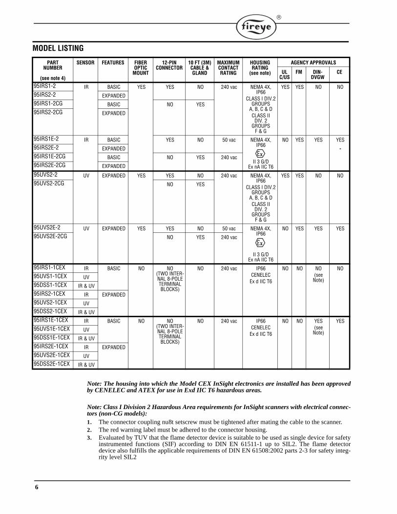
MODEL LISTING
Note: The housing into which the Model CEX InSight electronics are installed has been approvedby CENELEC and ATEX for use in Exd IIC T6 hazardous areas.
Note: Class I Division 2 Hazardous Area requirements for InSight scanners with electrical connec-tors (non-CG models):1. The connector coupling nu8t setscrew must be tightened after mating the cable to the scanner.2. The red warning label must be adhered to the connector housing.3. Evaluated by TUV that the flame detector device is suitable to be used as single device for safety
instrumented functions (SIF) according to DIN EN 61511-1 up to SIL2. The flame detectordevice also fulfills the applicable requirements of DIN EN 61508:2002 parts 2-3 for safety integ-rity level SIL2
PART NUMBER
(see note 4)
SENSOR FEATURES FIBEROPTIC
MOUNT
12-PINCONNECTOR
10 FT (3M)CABLE & GLAND
MAXIMUM CONTACT RATING
HOUSING RATING
(see note)
AGENCY APPROVALS
ULC/US
FM DIN-DVGW
CE
95IRS1-2 IR BASIC YES YES NO 240 vac NEMA 4X, IP66
CLASS I DIV.2GROUPS
A, B, C & DCLASS II
DIV. 2 GROUPS
F & G
YES YES NO NO95IRS2-2 EXPANDED95IRS1-2CG BASIC NO YES95IRS2-2CG EXPANDED
95IRS1E-2 IR BASIC YES NO 50 vac NEMA 4X, IP66
II 3 G/DEx nA IIC T6
NO YES YES YES95IRS2E-2 EXPANDED95IRS1E-2CG BASIC NO YES 240 vac95IRS2E-2CG EXPANDED
95UVS2-2 UV EXPANDED YES YES NO 240 vac NEMA 4X, IP66
CLASS I DIV.2GROUPS
A, B, C & DCLASS II
DIV. 2GROUPS
F & G
YES YES NO NO95UVS2-2CG NO YES
95UVS2E-2 UV EXPANDED YES YES NO 50 vac NEMA 4X, IP66
II 3 G/DEx nA IIC T6
NO YES YES YES95UVS2E-2CG NO YES 240 vac
95IRS1-1CEX IR BASIC NO NO(TWO INTER-NAL 8-POLE TERMINAL BLOCKS)
NO 240 vac IP66 CENELEC
Ex d IIC T6
NO NO NO(see Note)
NO95UVS1-1CEX UV95DSS1-1CEX IR & UV95IRS2-1CEX IR EXPANDED95UVS2-1CEX UV95DSS2-1CEX IR & UV95IRS1E-1CEX IR BASIC NO NO
(TWO INTER-NAL 8-POLE TERMINAL BLOCKS)
NO 240 vac IP66 CENELEC
Ex d IIC T6
NO NO YES(see Note)
YES95UVS1E-1CEX UV95DSS1E-1CEX IR & UV95IRS2E-1CEX IR EXPANDED95UVS2E-1CEX UV95DSS2E-1CEX IR & UV
7
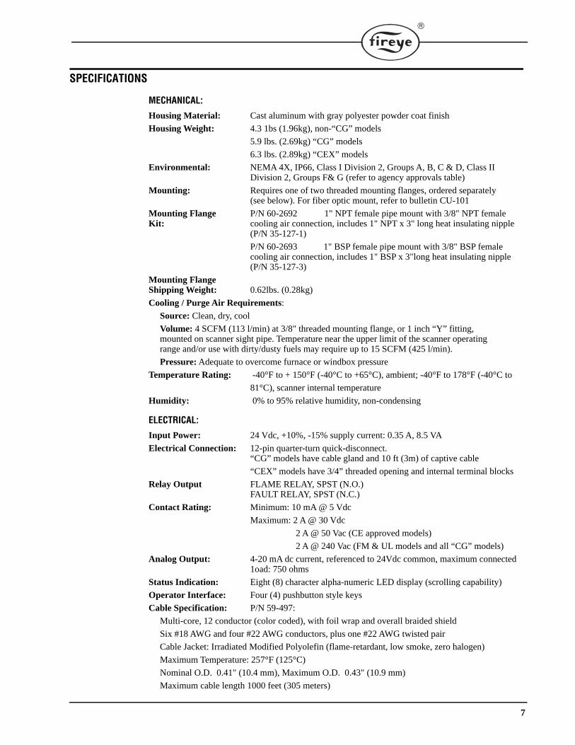
SPECIFICATIONS
MECHANICAL:
Housing Material: Cast aluminum with gray polyester powder coat finish
Housing Weight: 4.3 1bs (1.96kg), non-“CG” models
5.9 lbs. (2.69kg) “CG” models
6.3 lbs. (2.89kg) “CEX” models
Environmental: NEMA 4X, IP66, Class I Division 2, Groups A, B, C & D, Class II Division 2, Groups F& G (refer to agency approvals table)
Mounting: Requires one of two threaded mounting flanges, ordered separately (see below). For fiber optic mount, refer to bulletin CU-101
Mounting Flange P/N 60-2692 1" NPT female pipe mount with 3/8" NPT female Kit: cooling air connection, includes 1" NPT x 3" long heat insulating nipple
(P/N 35-127-1)
P/N 60-2693 1" BSP female pipe mount with 3/8" BSP femalecooling air connection, includes 1" BSP x 3"long heat insulating nipple(P/N 35-127-3)
Mounting Flange Shipping Weight: 0.62lbs. (0.28kg)
Cooling / Purge Air Requirements:
Source: Clean, dry, cool
Volume: 4 SCFM (113 l/min) at 3/8" threaded mounting flange, or 1 inch “Y” fitting, mounted on scanner sight pipe. Temperature near the upper limit of the scanner operatingrange and/or use with dirty/dusty fuels may require up to 15 SCFM (425 l/min).
Pressure: Adequate to overcome furnace or windbox pressure
Temperature Rating: -40°F to + 150°F (-40°C to +65°C), ambient; -40°F to 178°F (-40°C to
81°C), scanner internal temperature
Humidity: 0% to 95% relative humidity, non-condensing
ELECTRICAL:
Input Power: 24 Vdc, +10%, -15% supply current: 0.35 A, 8.5 VA
Electrical Connection: 12-pin quarter-turn quick-disconnect. “CG” models have cable gland and 10 ft (3m) of captive cable
“CEX” models have 3/4” threaded opening and internal terminal blocks
Relay Output FLAME RELAY, SPST (N.O.)FAULT RELAY, SPST (N.C.)
Contact Rating: Minimum: 10 mA @ 5 Vdc
Maximum: 2 A @ 30 Vdc
2 A @ 50 Vac (CE approved models)
2 A @ 240 Vac (FM & UL models and all “CG” models)
Analog Output: 4-20 mA dc current, referenced to 24Vdc common, maximum connected1oad: 750 ohms
Status Indication: Eight (8) character alpha-numeric LED display (scrolling capability)
Operator Interface: Four (4) pushbutton style keys
Cable Specification: P/N 59-497:
Multi-core, 12 conductor (color coded), with foil wrap and overall braided shield
Six #18 AWG and four #22 AWG conductors, plus one #22 AWG twisted pair
Cable Jacket: Irradiated Modified Polyolefin (flame-retardant, low smoke, zero halogen)
Maximum Temperature: 257°F (125°C)
Nominal O.D. 0.41" (10.4 mm), Maximum O.D. 0.43" (10.9 mm)
Maximum cable length 1000 feet (305 meters)

8
INSTALLATION NOTESThe InSight flame scanners determine the presence or absence of flame by monitoring the frequencyspectrum of the flame. The scanner should initially be mounted so that the primary combustion zoneis within the scanner’s line of sight.
The location and sighting instructions listed in the following sections are rough guidelines for thelocation of the scanner. The scanner provides feedback via its LED display to assist in the adjustmentand proper alignment of the flame scanner. Refer to the setpoint procedures described in this bulletin.
Note: An acceptable scanner location must ensure the following:
Reliable main flame and/or ignitor flame detection at all air flow and furnace loads (ranges of fuelfiring).
Rejection of the ignitor flame if too short or in the wrong position to ignite the main flame reliably,thus prohibiting the delivery of fuel to the burner.
Note: Due to the microprocessor based design of the InSight scanner, the heat insulating nipple (P/N 35-127-1 or 35-127-3) must be used to isolate the scanner from ground and to reduce con-ducted energy and noise. See Figure 7. The nipple is included in mounting flange kit P/N 60-2692,60-2693.
INSTALLATION PROCEDURE
WARNING: Protective filtered lenses should be worn when viewing flame. Infrared andultraviolet energy from the flame can be damaging to the eyes.
1. The best results are obtained when the scanner is aimed so that the scanner’s line of sight inter-sects the burner center at a slight angle (e.g. 5 degrees) and sees a maximum of the primary com-bustion zone, as shown in Figure 4. If only one scanner is used per burner, the line of sightshould also intersect the igniting flame.
2. For installations where separate scanners are used to monitor main and ignitor flames, the mainflame scanner should be sighted so it does not detect the ignitor flame.
3. The scanner should have an unrestricted view of flame as far as possible. Physical obstructionssuch as air register blades, interfering vanes, or other hardware should be cut away or notched sothey do not fall within the scanner’s line of sight as shown in Figure 6.
Note: Always check with the burner manufacturer before you trim the register blades.FIGURE 4. SINGLE BURNER SCANNER SIGHTING
4. Consideration must be given to burner secondary air rotation, some burners have clockwise(CW) air rotation and others have counterclockwise (CCW) air rotation. If combustion air entersthe furnace with a rotational movement of sufficient velocity to deflect the ignitor flame in thedirection of rotation, position the scanner 10 to 30 degrees downstream of the ignitor as shown inFigure 5 and close to the periphery of the burner throat (See Figure 4).
PRIMARYCOMBUSTION
ZONE
AIR REGISTERBLADES
SCANNERLINE OFSIGHT
BURNERTHROAT
FLAMEENVELOPE
BURNERCENTER LINE
BASE
9
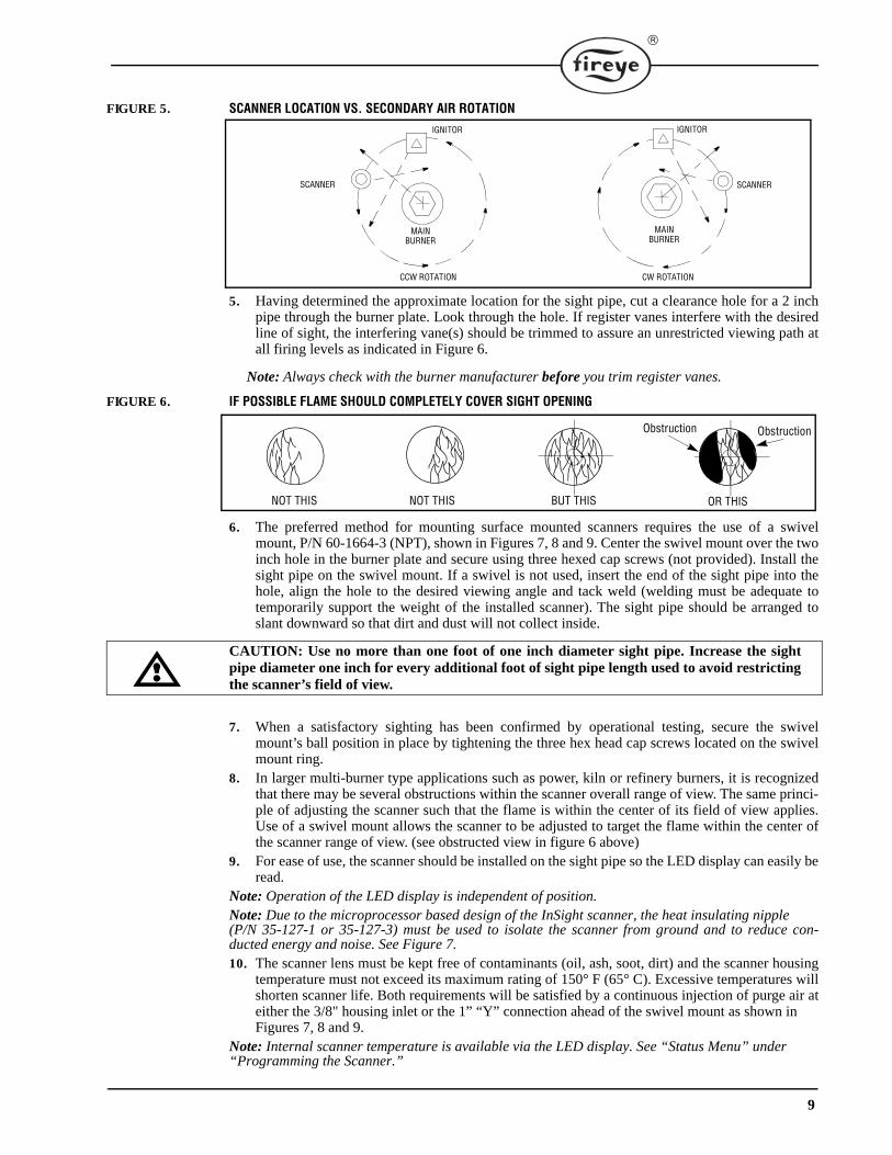
FIGURE 5. SCANNER LOCATION VS. SECONDARY AIR ROTATION
5. Having determined the approximate location for the sight pipe, cut a clearance hole for a 2 inchpipe through the burner plate. Look through the hole. If register vanes interfere with the desiredline of sight, the interfering vane(s) should be trimmed to assure an unrestricted viewing path atall firing levels as indicated in Figure 6.
Note: Always check with the burner manufacturer before you trim register vanes.
FIGURE 6. IF POSSIBLE FLAME SHOULD COMPLETELY COVER SIGHT OPENING
6. The preferred method for mounting surface mounted scanners requires the use of a swivelmount, P/N 60-1664-3 (NPT), shown in Figures 7, 8 and 9. Center the swivel mount over the twoinch hole in the burner plate and secure using three hexed cap screws (not provided). Install thesight pipe on the swivel mount. If a swivel is not used, insert the end of the sight pipe into thehole, align the hole to the desired viewing angle and tack weld (welding must be adequate totemporarily support the weight of the installed scanner). The sight pipe should be arranged toslant downward so that dirt and dust will not collect inside.
CAUTION: Use no more than one foot of one inch diameter sight pipe. Increase the sightpipe diameter one inch for every additional foot of sight pipe length used to avoid restrictingthe scanner’s field of view.
7. When a satisfactory sighting has been confirmed by operational testing, secure the swivelmount’s ball position in place by tightening the three hex head cap screws located on the swivelmount ring.
8. In larger multi-burner type applications such as power, kiln or refinery burners, it is recognizedthat there may be several obstructions within the scanner overall range of view. The same princi-ple of adjusting the scanner such that the flame is within the center of its field of view applies.Use of a swivel mount allows the scanner to be adjusted to target the flame within the center ofthe scanner range of view. (see obstructed view in figure 6 above)
9. For ease of use, the scanner should be installed on the sight pipe so the LED display can easily beread.
Note: Operation of the LED display is independent of position.Note: Due to the microprocessor based design of the InSight scanner, the heat insulating nipple (P/N 35-127-1 or 35-127-3) must be used to isolate the scanner from ground and to reduce con-ducted energy and noise. See Figure 7.10. The scanner lens must be kept free of contaminants (oil, ash, soot, dirt) and the scanner housing
temperature must not exceed its maximum rating of 150° F (65° C). Excessive temperatures willshorten scanner life. Both requirements will be satisfied by a continuous injection of purge air ateither the 3/8" housing inlet or the 1” “Y” connection ahead of the swivel mount as shown in Figures 7, 8 and 9.
Note: Internal scanner temperature is available via the LED display. See “Status Menu” under “Programming the Scanner.”
IGNITOR
SCANNER
MAINBURNER
CCW ROTATION
IGNITOR
SCANNER
MAIN
CW ROTATION
BURNER
BUT THISNOT THIS NOT THIS OR THIS
ObstructionObstruction
10
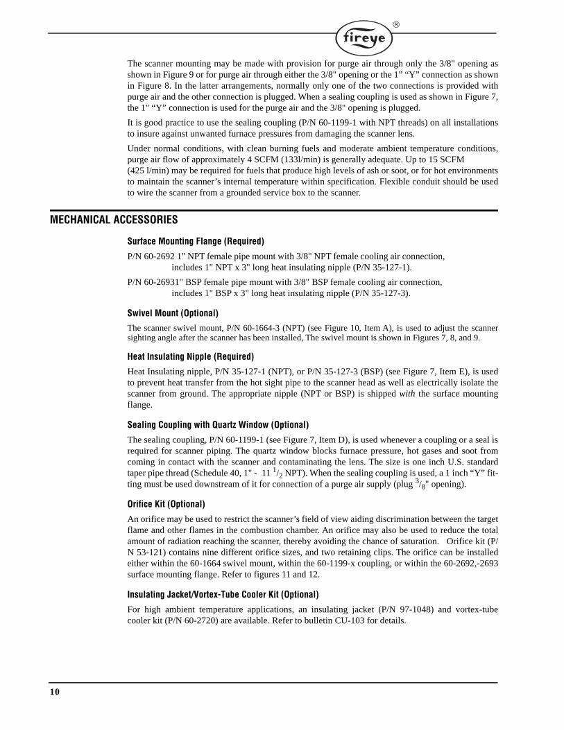
The scanner mounting may be made with provision for purge air through only the 3/8" opening asshown in Figure 9 or for purge air through either the 3/8" opening or the 1” “Y” connection as shownin Figure 8. In the latter arrangements, normally only one of the two connections is provided withpurge air and the other connection is plugged. When a sealing coupling is used as shown in Figure 7,the 1" “Y” connection is used for the purge air and the 3/8" opening is plugged.
It is good practice to use the sealing coupling (P/N 60-1199-1 with NPT threads) on all installationsto insure against unwanted furnace pressures from damaging the scanner lens.
Under normal conditions, with clean burning fuels and moderate ambient temperature conditions,purge air flow of approximately 4 SCFM (133l/min) is generally adequate. Up to 15 SCFM (425 l/min) may be required for fuels that produce high levels of ash or soot, or for hot environmentsto maintain the scanner’s internal temperature within specification. Flexible conduit should be usedto wire the scanner from a grounded service box to the scanner.
MECHANICAL ACCESSORIES
Surface Mounting Flange (Required)
P/N 60-2692 1" NPT female pipe mount with 3/8" NPT female cooling air connection, includes 1" NPT x 3" long heat insulating nipple (P/N 35-127-1).
P/N 60-26931" BSP female pipe mount with 3/8" BSP female cooling air connection,includes 1" BSP x 3" long heat insulating nipple (P/N 35-127-3).
Swivel Mount (Optional)
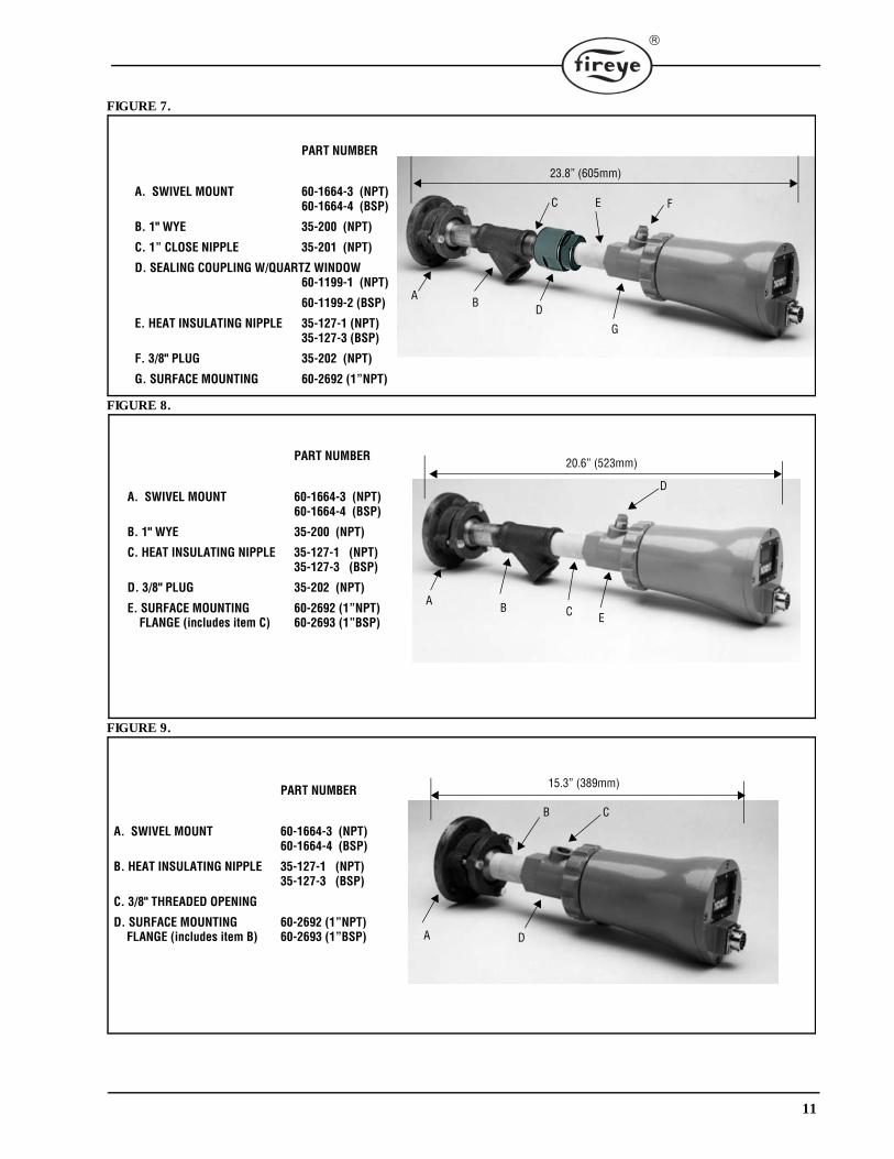
The scanner swivel mount, P/N 60-1664-3 (NPT) (see Figure 10, Item A), is used to adjust the scannersighting angle after the scanner has been installed, The swivel mount is shown in Figures 7, 8, and 9.
Heat Insulating Nipple (Required)
Heat Insulating nipple, P/N 35-127-1 (NPT), or P/N 35-127-3 (BSP) (see Figure 7, Item E), is usedto prevent heat transfer from the hot sight pipe to the scanner head as well as electrically isolate thescanner from ground. The appropriate nipple (NPT or BSP) is shipped with the surface mountingflange.
Sealing Coupling with Quartz Window (Optional)
The sealing coupling, P/N 60-1199-1 (see Figure 7, Item D), is used whenever a coupling or a seal isrequired for scanner piping. The quartz window blocks furnace pressure, hot gases and soot fromcoming in contact with the scanner and contaminating the lens. The size is one inch U.S. standardtaper pipe thread (Schedule 40, 1" - 11 1/2 NPT). When the sealing coupling is used, a 1 inch “Y” fit-ting must be used downstream of it for connection of a purge air supply (plug 3/8" opening).
Orifice Kit (Optional)
An orifice may be used to restrict the scanner’s field of view aiding discrimination between the targetflame and other flames in the combustion chamber. An orifice may also be used to reduce the totalamount of radiation reaching the scanner, thereby avoiding the chance of saturation. Orifice kit (P/N 53-121) contains nine different orifice sizes, and two retaining clips. The orifice can be installedeither within the 60-1664 swivel mount, within the 60-1199-x coupling, or within the 60-2692,-2693surface mounting flange. Refer to figures 11 and 12.
Insulating Jacket/Vortex-Tube Cooler Kit (Optional)
For high ambient temperature applications, an insulating jacket (P/N 97-1048) and vortex-tubecooler kit (P/N 60-2720) are available. Refer to bulletin CU-103 for details.
11
FIGURE 7.
FIGURE 8.
FIGURE 9.
PART NUMBER
A. SWIVEL MOUNT 60-1664-3 (NPT)60-1664-4 (BSP)
B. 1" WYE 35-200 (NPT)
C. 1” CLOSE NIPPLE 35-201 (NPT)
D. SEALING COUPLING W/QUARTZ WINDOW60-1199-1 (NPT)
60-1199-2 (BSP)
E. HEAT INSULATING NIPPLE 35-127-1 (NPT)35-127-3 (BSP)
F. 3/8" PLUG 35-202 (NPT)
G. SURFACE MOUNTING 60-2692 (1”NPT)
C E F
AB
D
G
23.8” (605mm)
PART NUMBER
A. SWIVEL MOUNT 60-1664-3 (NPT)60-1664-4 (BSP)
B. 1" WYE 35-200 (NPT)
C. HEAT INSULATING NIPPLE 35-127-1 (NPT)35-127-3 (BSP)
D. 3/8" PLUG 35-202 (NPT)
E. SURFACE MOUNTING 60-2692 (1”NPT)FLANGE (includes item C) 60-2693 (1”BSP)
AB C
D
E
20.6” (523mm)
PART NUMBER
A. SWIVEL MOUNT 60-1664-3 (NPT)60-1664-4 (BSP)
B. HEAT INSULATING NIPPLE 35-127-1 (NPT)35-127-3 (BSP)
C. 3/8" THREADED OPENING
D. SURFACE MOUNTING 60-2692 (1”NPT)FLANGE (includes item B) 60-2693 (1”BSP)
CB
A D
15.3” (389mm)
12
FIGURE 10.
FIGURE 11.
ORIFICESFigure Qty. Part Number Description11 1 53-121 Orifice Kit: Contains following items:11A 1 53-121-2 Orifice: Diameter = 0.062"11B 1 53-121-3 Orifice: Diameter = 0.078"11C 1 53-121-4 Orifice: Diameter = 0.093"11D 1 53-121-5 Orifice: Diameter = 0.109"11E 1 53-121-6 Orifice: Diameter = 0.125"11F 1 53-121-7 Orifice: Diameter = 0.187"11G 1 53-121-8 Orifice: Diameter = 0.250"11H 1 53-121-9 Orifice: Diameter = 0.375"11I 1 53-121-10 Orifice: Diameter = 0.500"11J 2 34-181 Orifice Retainer
PART NUMBER
A. SWIVEL MOUNT 60-1664-3 (NPT)
SWIVEL MOUNT 60-1664-4 (BSP)
B. SEALING COUPLING W/QUARTZ WINDOW60-1199-1 (NPT)
60-1199-2 (BSP)
C. SCANNER CABLE 59-497
A
B
C
A-I. Orifices: 0.062" - 0.5" DIAJ. Orifice Retainer 34-181K. Heat Insulating Nipple 35-127-1 (NPT)
Heat Insulating Nipple 35-127-3 (BSP)

13
FIGURE 12.
ELECTRICAL ACCESSORIES (see note)
Note: Class I Division 2 Hazardous Area requirements for InSight scanners with electrical con-nectors (non-CG models):1. The connector coupling nut setscrew must be tightened after mating the cable to the scanner.2. The red warning label must be adhered to the connector housing.
Scanner Cable, P/N 59-497
Fireye recommends P/N 59-497 multi-core, 12 conductor (color coded), foil wrap and overallbraided shield cable. This cable includes six #18 AWG and four #22 AWG conductors, plus one #22AWG twisted pair. The cable jacket is Irradiated Modified Polyolefin (flame-retardant, low smoke,zero halogen) with a maximum diameter of 0.43" (10.9 mm). Maximum temperature: 257°F(125°C). The maximum cable length is 1000 feet (305 meters) per scanner. This raw stock cablerequires the Quick-Disconnect Kit described below. Refer to Figure 14 for color code and connec-tion information.
Quick-Disconnect Kit, P/N 129-164, 129-164R, 129-164C, 129-164RC
A twelve-pin (male) electrical connector is factory installed on non-“CG” InSight scanners. Fireyeoffers the mating (female) connector for field installation onto the 59-497 cable. Refer to Quick-Dis-connect assembly instructions. P/N 129-164 is straight, P/N 129-164R is right-angle. P/N 129-164Cand 129-164RC are supplied with fittings for use with 1/2" flexible conduit.
Scanner Cable with Female Connector, P/N 59-497-XXX, -XXXR, -XXXC, -XXXRC
Fireye offers the 59-497 12-conductor cable in pre-cut lengths with the female quick-disconnect fac-tory installed. These assemblies are offered in lengths from 10 feet (3m) to 300 feet (91m). P/N 59-497-XXXR has a right-angle connector. P/N 59-497-XXXC and 59-497-XXXRC are sup-plied with fittings for use with 1/2" flexible conduit.
Wiring Harness Assembly, P/N 61-6944-XXX, -XXXR
If remote communication is required (Model S2 only), and the distance between the InSight scannerand the control room exceeds 200 feet (61m), then a small junction box must be installed near eachscanner.
The two communications wires must be separated out of the twelve-conductor scanner cable at thejunction box and wired independently in a multi-drop (“daisy-chain”) configuration to each scannerin the loop, and finally to the computer. The Fireye Wiring Harness Assembly, available in lengthsfrom 3 to 50 feet (0.9 to 15.2m), provides a convenient method to accomplish this.
On one end, the harness has a female quick-disconnect to connect to the non-“CG” InSight scanner.Harness part numbers ending in “R” have a 90° quick-disconnect. Fireye twelve-conductor cable, P/
SWIVEL MOUNT
ORIFICE RETAINER
PURGE
ORIFICE
FIELD OF VIEW
FIELD OF VIEW
BALL
AIR SUPPLY
3/8" PLUG 1" SWIVEL MOUNT
60-1199-1,2SEALING COUPLING
14
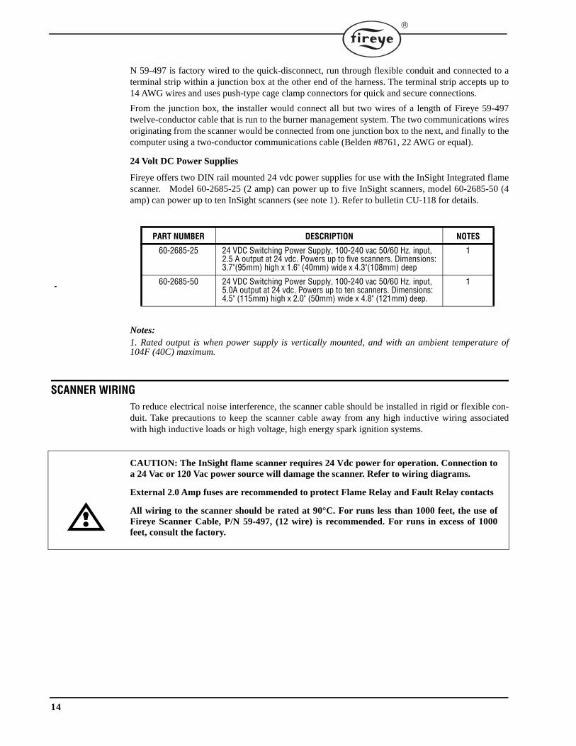
N 59-497 is factory wired to the quick-disconnect, run through flexible conduit and connected to aterminal strip within a junction box at the other end of the harness. The terminal strip accepts up to14 AWG wires and uses push-type cage clamp connectors for quick and secure connections.
From the junction box, the installer would connect all but two wires of a length of Fireye 59-497twelve-conductor cable that is run to the burner management system. The two communications wiresoriginating from the scanner would be connected from one junction box to the next, and finally to thecomputer using a two-conductor communications cable (Belden #8761, 22 AWG or equal).
24 Volt DC Power Supplies
Fireye offers two DIN rail mounted 24 vdc power supplies for use with the InSight Integrated flamescanner. Model 60-2685-25 (2 amp) can power up to five InSight scanners, model 60-2685-50 (4amp) can power up to ten InSight scanners (see note 1). Refer to bulletin CU-118 for details.
Notes:1. Rated output is when power supply is vertically mounted, and with an ambient temperature of104F (40C) maximum.
SCANNER WIRINGTo reduce electrical noise interference, the scanner cable should be installed in rigid or flexible con-duit. Take precautions to keep the scanner cable away from any high inductive wiring associatedwith high inductive loads or high voltage, high energy spark ignition systems.
CAUTION: The InSight flame scanner requires 24 Vdc power for operation. Connection toa 24 Vac or 120 Vac power source will damage the scanner. Refer to wiring diagrams.
External 2.0 Amp fuses are recommended to protect Flame Relay and Fault Relay contacts
All wiring to the scanner should be rated at 90°C. For runs less than 1000 feet, the use ofFireye Scanner Cable, P/N 59-497, (12 wire) is recommended. For runs in excess of 1000feet, consult the factory.
PART NUMBER DESCRIPTION NOTES
60-2685-25 24 VDC Switching Power Supply, 100-240 vac 50/60 Hz. input, 2.5 A output at 24 vdc. Powers up to five scanners. Dimensions: 3.7"(95mm) high x 1.6" (40mm) wide x 4.3"(108mm) deep
1
60-2685-50 24 VDC Switching Power Supply, 100-240 vac 50/60 Hz. input, 5.0A output at 24 vdc. Powers up to ten scanners. Dimensions: 4.5" (115mm) high x 2.0" (50mm) wide x 4.8" (121mm) deep.
1
15
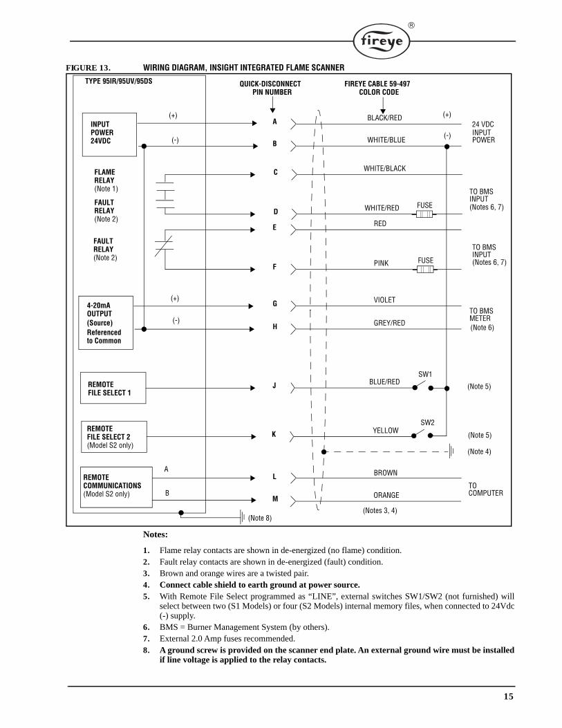
FIGURE 13. WIRING DIAGRAM, INSIGHT INTEGRATED FLAME SCANNER
Notes:
1. Flame relay contacts are shown in de-energized (no flame) condition.2. Fault relay contacts are shown in de-energized (fault) condition.3. Brown and orange wires are a twisted pair.4. Connect cable shield to earth ground at power source.5. With Remote File Select programmed as “LINE”, external switches SW1/SW2 (not furnished) will
select between two (S1 Models) or four (S2 Models) internal memory files, when connected to 24Vdc(-) supply.
6. BMS = Burner Management System (by others).7. External 2.0 Amp fuses recommended.8. A ground screw is provided on the scanner end plate. An external ground wire must be installed
if line voltage is applied to the relay contacts.
TYPE 95IR/95UV/95DS QUICK-DISCONNECTPIN NUMBER
FIREYE CABLE 59-497COLOR CODE
A BLACK/RED
B WHITE/BLUE
C WHITE/BLACK
D WHITE/RED
E RED
F PINK
G VIOLET
H GREY/RED
J BLUE/RED
K YELLOW
L BROWN
M ORANGE
(Notes 3, 4)
A
B
(+)
(-)
(+)
(-)
INPUT POWER24VDC
FAULT RELAY(Note 2)
4-20mAOUTPUT
Referenced
REMOTEFILE SELECT 1
REMOTEFILE SELECT 2(Model S2 only)
REMOTECOMMUNICATIONS(Model S2 only)
TO COMPUTER
(Note 5)
(Note 5)
TO BMSMETER
TO BMSINPUT
TO BMSINPUT
INPUT POWER
SW1
SW2
to Common
(+)
(-)
(Note 6)
(Notes 6, 7)
(Notes 6, 7)
24 VDC
FLAME RELAY(Note 1)
FAULT RELAY(Note 2)
FUSE
FUSE
(Note 4)
(Note 8)
(Source)

16
REMOTE FILE SELECTIONThe InSight scanners have more than one internal memory file. The user has the option of storingdifferent scanner setpoints for different operating conditions (e.g. Gas / Oil, Pilot / Main, Low Fire /High Fire, etc.) in these files. The “S1” models have two programmable files (A & B), and “S2”models have four (A,B,C, & D). With RFS selected as “LINE”, one or two external switches (sup-plied by user) will select between the files when the RFS1 or RFS2 wires are connected to24 vdc (-).
RFS1 (Blue) RFS2 (Yellow) File Selected
(Note 1)
Open Open A
Closed Open B
Open Closed C
Closed Closed D
Note 1: RFS2 function is available in the “S2” models only.Note 2: The user may also select RFS as “KEY” which will allow manual file selection at the scanner keypad.Note 3: With FM & UL approved “S2” models, the user may also select RFS as “COMM” whichwill allow manual selection at a remote computer running Fireye software. This feature is not available with CE approved “S2E” models.Note 4: Fireye recommends the use of shielded cable for the two remote file select switches (orrelays). The switch contacts should be rated for low current operation (3mA dc).
ASSEMBLY INSTRUCTIONS, QUICK DISCONNECT KIT P/N 129-164FIGURE 14. 59-497 CABLE, CONDUCTOR ORIENTATION
WT/RD
COLOR CODE:
BK = BLACKRD = REDWT = WHITEPK = PINKVT = VIOLETGY = GREYBU = BLUEYL = YELLOWBN = BROWNOR = ORANGE
RDPK
VT
GY/RD
BU/RD
BN
OR
YLBK/RD
WT/BK
WT/BU
For ease of assembly, install the 129-164 connector on the 59-497 cable end where the 3 white wires are clockwise to the red wire, as shown.
PLUG CONNECTORORANGE GROMMET INSTALLED
17
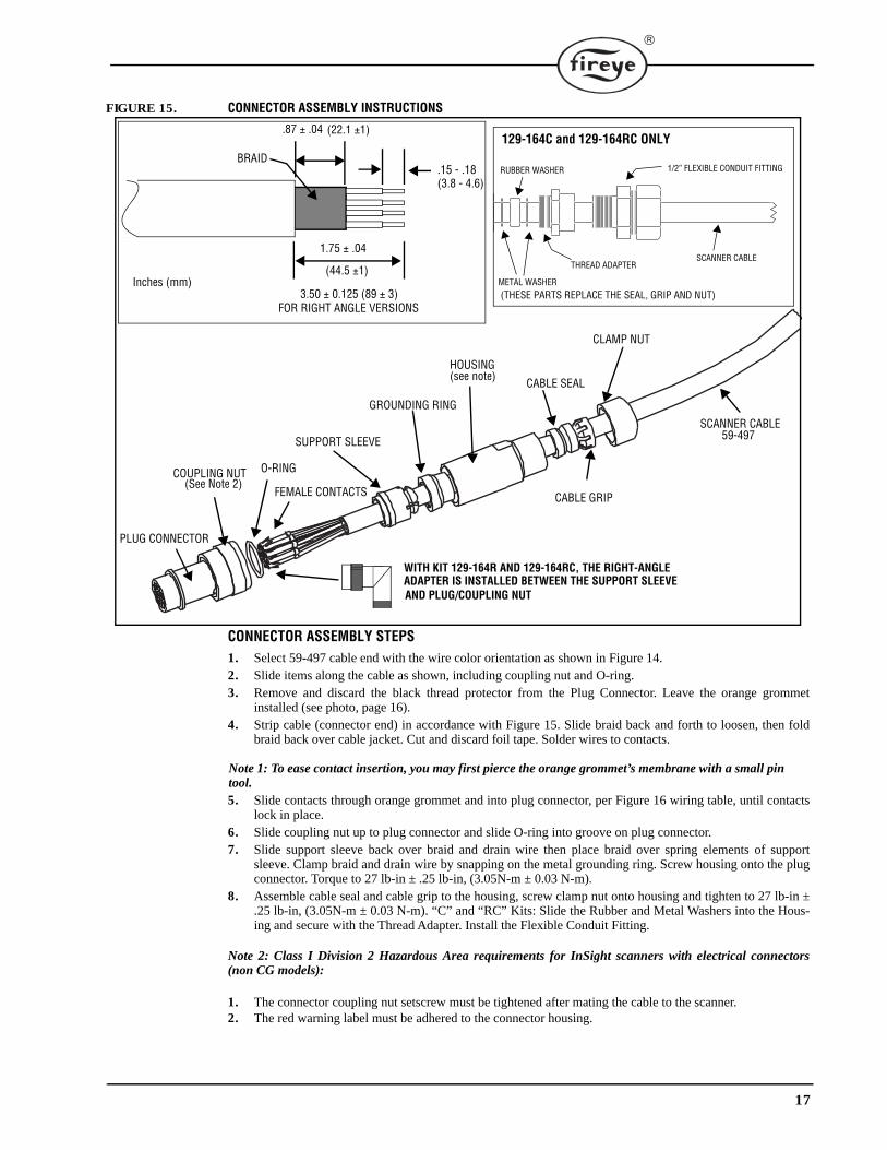
FIGURE 15. CONNECTOR ASSEMBLY INSTRUCTIONS
CONNECTOR ASSEMBLY STEPS1. Select 59-497 cable end with the wire color orientation as shown in Figure 14.2. Slide items along the cable as shown, including coupling nut and O-ring.3. Remove and discard the black thread protector from the Plug Connector. Leave the orange grommet
installed (see photo, page 16).4. Strip cable (connector end) in accordance with Figure 15. Slide braid back and forth to loosen, then fold
braid back over cable jacket. Cut and discard foil tape. Solder wires to contacts.
Note 1: To ease contact insertion, you may first pierce the orange grommet’s membrane with a small pintool.5. Slide contacts through orange grommet and into plug connector, per Figure 16 wiring table, until contacts
lock in place.6. Slide coupling nut up to plug connector and slide O-ring into groove on plug connector.7. Slide support sleeve back over braid and drain wire then place braid over spring elements of support
sleeve. Clamp braid and drain wire by snapping on the metal grounding ring. Screw housing onto the plugconnector. Torque to 27 lb-in ± .25 lb-in, (3.05N-m ± 0.03 N-m).
8. Assemble cable seal and cable grip to the housing, screw clamp nut onto housing and tighten to 27 lb-in ±.25 lb-in, (3.05N-m ± 0.03 N-m). “C” and “RC” Kits: Slide the Rubber and Metal Washers into the Hous-ing and secure with the Thread Adapter. Install the Flexible Conduit Fitting.
Note 2: Class I Division 2 Hazardous Area requirements for InSight scanners with electrical connectors(non CG models):
1. The connector coupling nut setscrew must be tightened after mating the cable to the scanner.2. The red warning label must be adhered to the connector housing.
.87 ± .04
.15 - .18
1.75 ± .04
BRAID
Inches (mm) (44.5 ±1)
(3.8 - 4.6)
(22.1 ±1)
3.50 ± 0.125 (89 ± 3) FOR RIGHT ANGLE VERSIONS
COUPLING NUT O-RING
SUPPORT SLEEVE
GROUNDING RING
HOUSING
CABLE SEAL
CABLE GRIP
SCANNER CABLE
CLAMP NUT
PLUG CONNECTOR
FEMALE CONTACTS
59-497
WITH KIT 129-164R AND 129-164RC, THE RIGHT-ANGLEADAPTER IS INSTALLED BETWEEN THE SUPPORT SLEEVE
129-164C and 129-164RC ONLY
METAL WASHER
RUBBER WASHER
SCANNER CABLETHREAD ADAPTER
1/2” FLEXIBLE CONDUIT FITTING
(THESE PARTS REPLACE THE SEAL, GRIP AND NUT)
AND PLUG/COUPLING NUT
(See Note 2)
(see note)
18
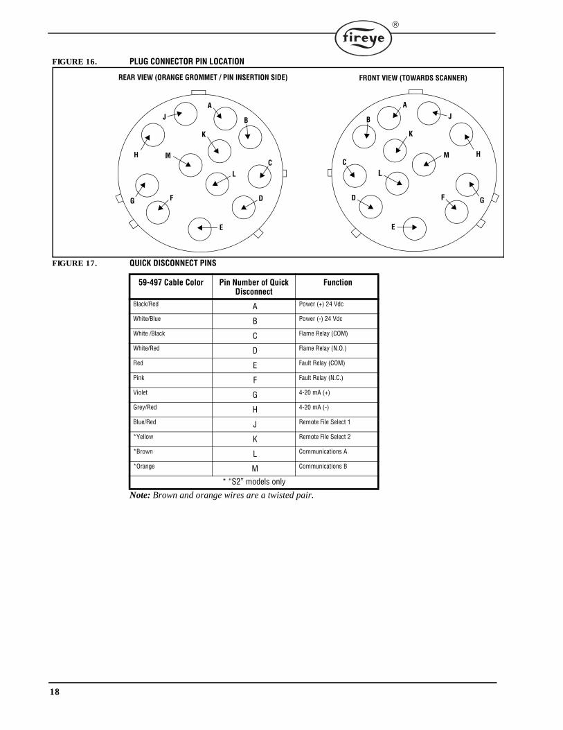
FIGURE 16. PLUG CONNECTOR PIN LOCATION
FIGURE 17. QUICK DISCONNECT PINS
Note: Brown and orange wires are a twisted pair.
59-497 Cable Color Pin Number of Quick Disconnect
Function
Black/Red A Power (+) 24 Vdc
White/Blue B Power (-) 24 Vdc
White /Black C Flame Relay (COM)
White/Red D Flame Relay (N.O.)
Red E Fault Relay (COM)
Pink F Fault Relay (N.C.)
Violet G 4-20 mA (+)
Grey/Red H 4-20 mA (-)
Blue/Red J Remote File Select 1
*Yellow K Remote File Select 2
*Brown L Communications A
*Orange M Communications B
* “S2” models only
REAR VIEW (ORANGE GROMMET / PIN INSERTION SIDE)
A
B
C
D
E
FG
H
J
K
L
M
A
B
C
D
E
F G
H
J
K
L
M
FRONT VIEW (TOWARDS SCANNER)
19
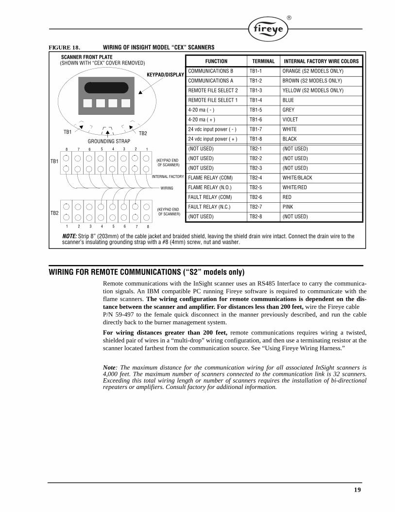
FIGURE 18. WIRING OF INSIGHT MODEL “CEX” SCANNERS
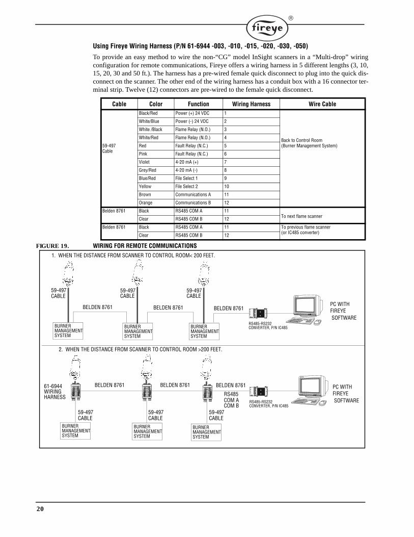
WIRING FOR REMOTE COMMUNICATIONS (“S2” models only)Remote communications with the InSight scanner uses an RS485 Interface to carry the communica-tion signals. An IBM compatible PC running Fireye software is required to communicate with theflame scanners. The wiring configuration for remote communications is dependent on the dis-tance between the scanner and amplifier. For distances less than 200 feet, wire the Fireye cable P/N 59-497 to the female quick disconnect in the manner previously described, and run the cabledirectly back to the burner management system.
For wiring distances greater than 200 feet, remote communications requires wiring a twisted,shielded pair of wires in a “multi-drop” wiring configuration, and then use a terminating resistor at thescanner located farthest from the communication source. See “Using Fireye Wiring Harness.”
Note: The maximum distance for the communication wiring for all associated InSight scanners is4,000 feet. The maximum number of scanners connected to the communication link is 32 scanners.Exceeding this total wiring length or number of scanners requires the installation of bi-directionalrepeaters or amplifiers. Consult factory for additional information.
FUNCTION TERMINAL INTERNAL FACTORY WIRE COLORS
COMMUNICATIONS B TB1-1 ORANGE (S2 MODELS ONLY)
COMMUNICATIONS A TB1-2 BROWN (S2 MODELS ONLY)
REMOTE FILE SELECT 2 TB1-3 YELLOW (S2 MODELS ONLY)
REMOTE FILE SELECT 1 TB1-4 BLUE
4-20 ma ( - ) TB1-5 GREY
4-20 ma ( + ) TB1-6 VIOLET
24 vdc input power ( - ) TB1-7 WHITE
24 vdc input power ( + ) TB1-8 BLACK
(NOT USED) TB2-1 (NOT USED)
(NOT USED) TB2-2 (NOT USED)
(NOT USED) TB2-3 (NOT USED)
FLAME RELAY (COM) TB2-4 WHITE/BLACK
FLAME RELAY (N.O.) TB2-5 WHITE/RED
FAULT RELAY (COM) TB2-6 RED
FAULT RELAY (N.C.) TB2-7 PINK
(NOT USED) TB2-8 (NOT USED)
SCANNER FRONT PLATE (SHOWN WITH “CEX” COVER REMOVED)
TB1 TB2
KEYPAD/DISPLAY
8 7 6 4 3 2 15
1 2 3 4 5 6 7 8
TB1
TB2
(KEYPAD END OF SCANNER)
(KEYPAD END OF SCANNER)
INTERNAL FACTORY
WIRING
GROUNDING STRAP
NOTE: Strip 8” (203mm) of the cable jacket and braided shield, leaving the shield drain wire intact. Connect the drain wire to the scanner’s insulating grounding strap with a #8 (4mm) screw, nut and washer.
20
Using Fireye Wiring Harness (P/N 61-6944 -003, -010, -015, -020, -030, -050)
To provide an easy method to wire the non-“CG” model InSight scanners in a “Multi-drop” wiringconfiguration for remote communications, Fireye offers a wiring harness in 5 different lengths (3, 10,15, 20, 30 and 50 ft.). The harness has a pre-wired female quick disconnect to plug into the quick dis-connect on the scanner. The other end of the wiring harness has a conduit box with a 16 connector ter-minal strip. Twelve (12) connectors are pre-wired to the female quick disconnect.
FIGURE 19. WIRING FOR REMOTE COMMUNICATIONS
Cable Color Function Wiring Harness Wire Cable
59-497Cable
Black/Red Power (+) 24 VDC 1
Back to Control Room(Burner Management System)
White/Blue Power (-) 24 VDC 2
White /Black Flame Relay (N.O.) 3
White/Red Flame Relay (N.O.) 4
Red Fault Relay (N.C.) 5
Pink Fault Relay (N.C.) 6
Violet 4-20 mA (+) 7
Grey/Red 4-20 mA (-) 8
Blue/Red File Select 1 9
Yellow File Select 2 10
Brown Communications A 11
Orange Communications B 12
Belden 8761 Black RS485 COM A 11To next flame scannerClear RS485 COM B 12
Belden 8761 Black RS485 COM A 11 To previous flame scanner (or IC485 converter)Clear RS485 COM B 12
BURNER
BELDEN 8761 BELDEN 8761
1. WHEN THE DISTANCE FROM SCANNER TO CONTROL ROOM< 200 FEET.
2. WHEN THE DISTANCE FROM SCANNER TO CONTROL ROOM >200 FEET.
BELDEN 8761 PC WITH
BELDEN 8761
59-497
BELDEN 8761 BELDEN 876161-6944WIRINGHARNESS RS485
COM ACOM B
SOFTWARE
CABLE59-497CABLE
59-497CABLE
RS485-RS232CONVERTER, P/N IC485
RS485-RS232CONVERTER, P/N IC485
59-497CABLE
59-497CABLE
MANAGEMENTSYSTEM
BURNER MANAGEMENT
SYSTEM
BURNER MANAGEMENT
SYSTEM
BURNER MANAGEMENT
SYSTEM
BURNER MANAGEMENT
SYSTEM
BURNER MANAGEMENT
SYSTEM
FIREYE
PC WITH
SOFTWAREFIREYE
59-497CABLE
21
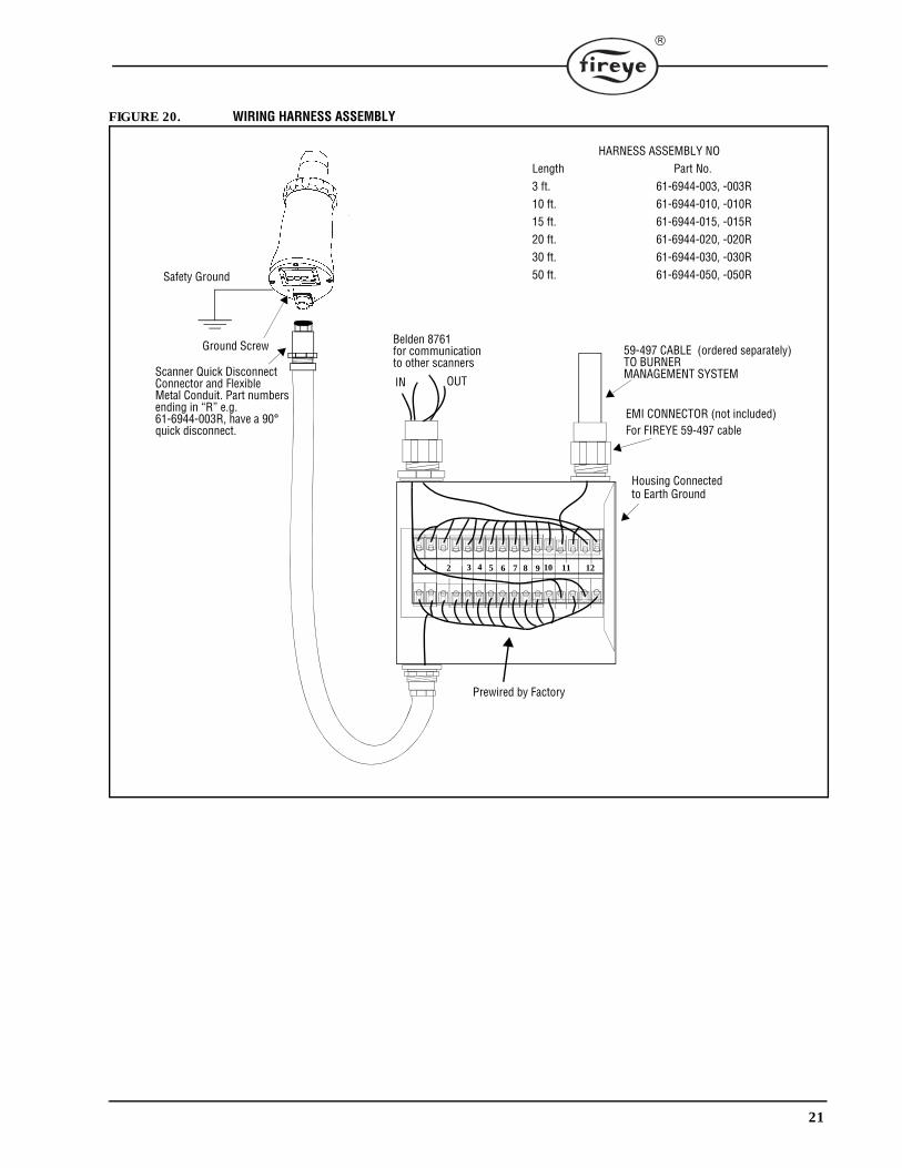
FIGURE 20. WIRING HARNESS ASSEMBLY
EMI CONNECTOR (not included)For FIREYE 59-497 cable
Housing Connectedto Earth Ground
59-497 CABLE (ordered separately)TO BURNER
Belden 8761for communicationto other scanners
IN OUTMANAGEMENT SYSTEM
1 3 5 74 6 8 9 10 11
HARNESS ASSEMBLY NOLength Part No.3 ft. 61-6944-003, -003R10 ft. 61-6944-010, -010R15 ft. 61-6944-015, -015R20 ft. 61-6944-020, -020R30 ft. 61-6944-030, -030R50 ft. 61-6944-050, -050R
2
Safety Ground
Ground Screw
12
Prewired by Factory
Scanner Quick DisconnectConnector and FlexibleMetal Conduit. Part numbersending in “R” e.g. 61-6944-003R, have a 90°quick disconnect.
22
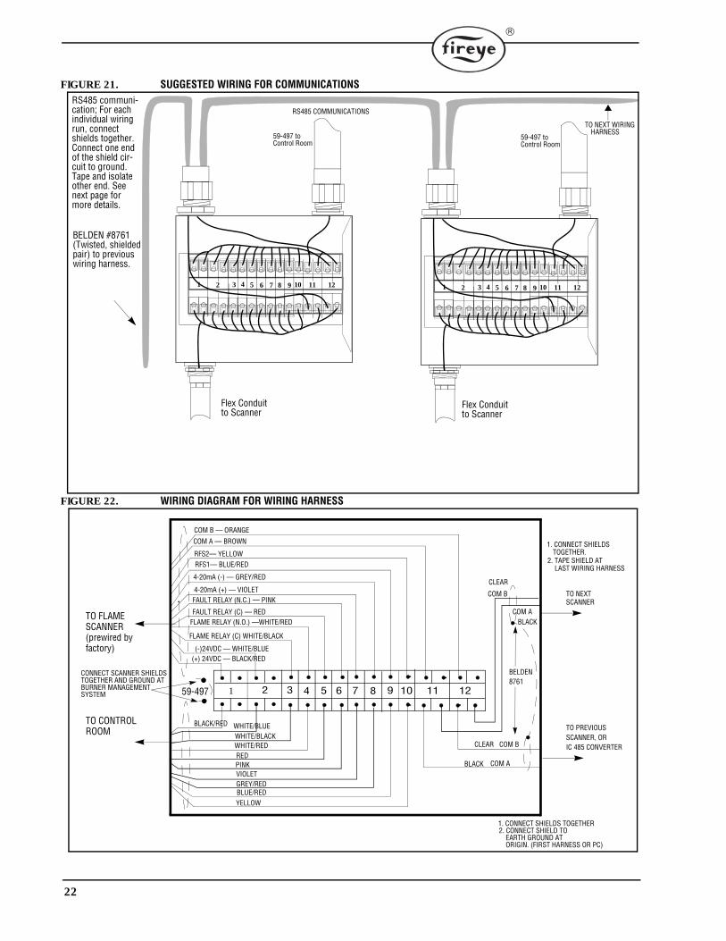
FIGURE 21. SUGGESTED WIRING FOR COMMUNICATIONS
FIGURE 22. WIRING DIAGRAM FOR WIRING HARNESS
RS485 COMMUNICATIONS
BELDEN #8761(Twisted, shieldedpair) to previous
RS485 communi-cation; For each individual wiring run, connect shields together. Connect one end of the shield cir-cuit to ground. Tape and isolate other end. See next page for more details.
wiring harness.
TO NEXT WIRINGHARNESS
1 3 5 74 6 8 9 10 112 12 1 3 5 74 6 8 9 10 112 12
Flex Conduit to Scanner
Flex Conduit to Scanner
59-497 toControl Room
59-497 toControl Room
2 3 4 5 6 11 12
(+) 24VDC — BLACK/RED(-)24VDC — WHITE/BLUE
FLAME RELAY (C) WHITE/BLACK
COM B — ORANGE
COM A — BROWN
RFS2— YELLOWRFS1— BLUE/RED
WHITE/BLUEBLACK/RED
YELLOW
PINK
WHITE/REDWHITE/BLACK
59-497
COM A
COM B
COM B
COM A
BELDEN8761
TO CONTROLROOM
TO FLAMESCANNER
1. CONNECT SHIELDS TOGETHER
1. CONNECT SHIELDS
2. CONNECT SHIELD TO EARTH GROUND AT ORIGIN. (FIRST HARNESS OR PC)
TO PREVIOUS SCANNER, OR
TO NEXTSCANNER
TOGETHER.2. TAPE SHIELD AT
LAST WIRING HARNESS
(prewired byfactory)
CLEAR
BLACK
CLEAR
BLACK
CONNECT SCANNER SHIELDS TOGETHER AND GROUND ATBURNER MANAGEMENT
IC 485 CONVERTER
1 7 8 9 10
FAULT RELAY (N.C.) — PINK
4-20mA (-) — GREY/RED
4-20mA (+) — VIOLET
FAULT RELAY (C) — REDFLAME RELAY (N.O.) —WHITE/RED
BLUE/REDGREY/REDVIOLET
SYSTEM
RED
23
GROUNDING AND SHIELDING TECHNIQUESFOR USE ON SCANNERS OR SCANNER CABLE LOCATED WITHIN 12" OF A HIGHENERGY OR HIGH VOLTAGE SOURCE.
1. Connect a safety ground to scanner housing (Figure 13).
2. The scanner and scanner cable (preferably within flexible conduit) MUST be located at least 12"from the ignition source.
3. Run a ground wire from the ignition transformer chassis to the ignitor assembly.4. Replace all frayed, cracked, or dirty (oily) ignition wire. Ignition wire must be in good working
condition.5. Electrically isolate the scanner from the burner using a heat insulating nipple provided with the
surface mounting flange.6. Cooling/Purge Air must be electrically isolated from the scanner (e.g. isolated short rubber
hose).
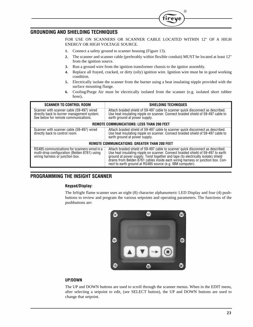
PROGRAMMING THE INSIGHT SCANNER
Keypad/Display:
The InSight flame scanner uses an eight (8) character alphanumeric LED Display and four (4) push-buttons to review and program the various setpoints and operating parameters. The functions of thepushbuttons are:
UP/DOWN
The UP and DOWN buttons are used to scroll through the scanner menus. When in the EDIT menu,after selecting a setpoint to edit, (see SELECT button), the UP and DOWN buttons are used tochange that setpoint.
SCANNER TO CONTROL ROOM SHIELDING TECHNIQUESScanner with scanner cable (59-497) wired directly back to burner management system. See below for remote communications.
Attach braided shield of 59-497 cable to scanner quick disconnect as described. Use heat insulating nipple on scanner. Connect braided shield of 59-497 cable to earth ground at power supply.
REMOTE COMMUNICATIONS: LESS THAN 200 FEETScanner with scanner cable (59-497) wired directly back to control room.
Attach braided shield of 59-497 cable to scanner quick disconnect as described. Use heat insulating nipple on scanner. Connect braided shield of 59-497 cable to earth ground at power supply.
REMOTE COMMUNICATIONS: GREATER THAN 200 FEETRS485 communications for scanners wired in a multi-drop configuration (Belden 8761) using wiring harness or junction box.
Attach braided shield of 59-497 cable to scanner quick disconnect as described. Use heat insulating nipple on scanner. Connect braided shield of 59-497 to earth ground at power supply. Twist together and tape (to electrically isolate) shield drains from Belden 8761 cables inside each wiring harness or junction box. Con-nect to earth ground at RS485 source (e.g. IBM computer).
24
SELECT
When in the EDIT menu, the UP / DOWN buttons are used to display the setpoints. Depressing theSELECT button displays the stored value of the setpoint, allowing it to be changed.
PROGRAM
The PROGRAM button saves a change made to a setpoint. It is also used to execute the Auto Tunefunction (“S2” Models only) or Pre-Edit function (“S1” Models only).
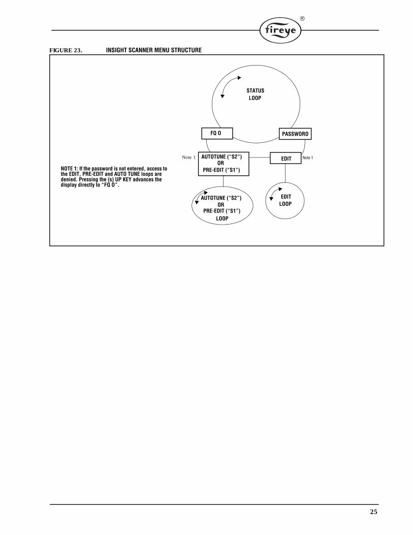
INSIGHT MENU STRUCTUREFor ease of operation, the InSight scanner contains three menus (or loops) accessed via the keypadand viewed on the scanner’s display.
STATUS MENU
The Status menu is the default display, and appears as soon as power is applied. Use the UP andDOWN buttons to scroll through the menu and view the current operating status. No operatingparameters can be changed from the Status menu. To change any setpoint, you must enter a four digitpassword then enter the Edit, or Pre-Edit (“S1”) or AutoTune (“S2”) menus.
EDIT MENU
The Edit Menu contains all the user-selected setpoints for the InSight scanner. The Edit menu isentered from the Status menu after first entering a four-digit password. In the Edit menu, the user isallowed to change the setpoints to optimize the scanner performance.
PRE-EDIT MENU (“S1” Models only)
From the Pre-Edit menu, the user views the flame signal intensity and physically aims the scannerfor optimum signal. The user then commands the scanner to set an appropriate internal front-endgain (FEG) level. As with the Edit menu, the Pre-Edit menu is entered from the Status menu afterfirst entering a four-digit password.
AUTOTUNE MENU (“S2” Models Only)
From the AutoTune menu, the user views the flame signal intensity and physically aims the scannerfor optimum signal.The user then commands the InSight scanner to analyze the flame ON and OFF(background radiation) conditions, and automatically select the optimum setpoints. As with the Editmenu, the AutoTune menu is entered from the Status menu after first entering a four-digit password.
25
FIGURE 23. INSIGHT SCANNER MENU STRUCTURE
FQ O PASSWORD
AUTOTUNE (“S2”) EDIT
LOOP
EDITLOOP
NOTE 1: If the password is not entered, access to the EDIT, PRE-EDIT and AUTO TUNE loops are denied. Pressing the (s) UP KEY advances the display directly to “FQ O”.
Note 1 Note 1
STATUS LOOP
PRE-EDIT (“S1”)
AUTOTUNE (“S2”)
PRE-EDIT (“S1”)OR
OR
26
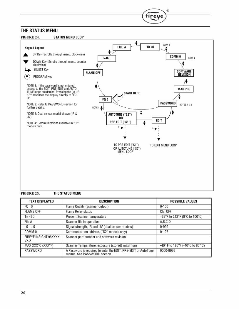
THE STATUS MENUFIGURE 24. STATUS MENU LOOP
FIGURE 25. THE STATUS MENU
TEXT DISPLAYED DESCRIPTION POSSIBLE VALUESFQ 0 Flame Quality (scanner output) 0-100FLAME OFF Flame Relay status ON, OFFT= 46C Present Scanner temperature +32°F to 212°F (0°C to 100°C)File A Scanner file in operation A,B,C,Di 0 u 0 Signal strength, IR and UV (dual sensor models) 0-999COMM 0 Communication address (“S2” models only) 0-127FIREYE INSIGHT 95XXXX VX.X
Scanner part number and software revision
MAX XXX°C (XXX°F) Scanner Temperature, exposure (stored) maximum -40° F to 185°F (-40°C to 85° C)PASSWORD A Password is required to enter the EDIT, PRE-EDIT or AutoTune
menus. See PASSWORD section.0000-9999
T=46C
FILE A
PASSWORD
FLAME OFF
FQ 0
START HERE
SELECT Key
PROGRAM Key
UP Key (Scrolls through menu, clockwise)
Keypad Legend
DOWN Key (Scrolls through menu, counter
EDIT
MAX 51C
SOFTWARE
COMM 0
iO uO
NOTES 1 & 2NOTE 1
TO EDIT MENU LOOPTO PRE-EDIT (“S1”)
NOTE 1: If the password is not entered, access to the EDIT, PRE-EDIT and AUTO TUNE loops are denied. Pressing the (s) UP KEY advances the display directly to “FQ O”.
NOTE 2: Refer to PASSWORD section for further details.
NOTE 3: Dual sensor model shown (IR & UV).
NOTE 4: Communications available in “S2” models only.
clockwise)
PRE-EDIT (“S1”)
AUTOTUNE (“S2”)
OR AUTOTUNE (“S2”)MENU LOOP
NOTE 3
NOTE 4
REVISION
OR
27
Flame Quality
The “Flame Quality” number can range from 0 to 100. It represents the scanner’s 4-20 mA analogflame signal strength OUTPUT (in percent), and is the scale by which the internal Flame Relay ONand OFF thresholds are set.
The “Flame Quality” number is determined by the input of the IR and / or UV sensor, (in dual sensormodels it is the sum of the two). This sensor signal strength value can be viewed in the Status menuas “Signal Strength”, see description below.
For clarity, the “Flame Quality” number is capped at 100, while under certain firing conditions theIR or UV “signal strength” (or their sum) may normally exceed 100 (maximum of 999).
In normal burner operation after the scanner has been properly setup, “FQ 100” will be displayedwith occasional movement depending on the stability of the flame.
Flame ON/OFF
This item refers to the energized / de-energized status of the internal Flame relay. “Flame ON” is dis-played when the flame quality rises above the relay “On Threshold” set in the Edit menu. When theflame quality drops below the relay “Off Threshold”, “Flame OFF” will be displayed.
Temperature
The scanner’s present temperature in degrees, expressed in either Fahrenheit or Centigrade depend-ing on which was selected in the Edit menu.
File Selected
The current running file is displayed. Choices are files “A, B” for S1 Models, and files “A, B, C, D”for S2 Models.
Signal Strength
The Signal Strength number represents the intensity of the “flame flicker”, as sensed by the IR and /or UV sensor(s), and is a function of the individual sensor “Gain” and “Bandpass” (flicker fre-quency) settings. The Signal Strength number is related to the Flame Quality number (see SignalStrength expanded description on following page).
Comm Address (“S2” Models Only)
This number refers to the remote communications address of the scanner. The address can rangefrom 0 to 127, as selected in the Edit menu. No two scanners in a communications loop should havethe same address.
Software Revision
This displays the part number and internal software revision.
Maximum Temperature
This displays the highest scanner temperature recorded.
Password
A four-digit Password is required to enter the EDIT and AUTOTUNE menus. If a Password is notentered, pressing the UP key will advance directly to the “Flame Quality” display, pressing theDOWN key will return to the “Maximum Temperature” display.
To enter the EDIT or AUTOTUNE menus, you must enter the four-digit Password. The followingexample is for the factory installed password of 0205:
28
1. With “PASSWORD” displayed, depress the SELECT key. “0xxx” will be displayed, the firstdigit (“0”) is adjustable. (If the factory password was changed, use the UP/DOWN keys to selectthe appropriate first digit).
2. With the first digit selected (e.g. “0xxx”) depress the PROGRAM key. “00xx” will be displayed,the second digit (“0”) is adjustable. Depress the UP key twice to display “2”. (If the factorypassword was changed, use the UP/DOWN keys to select the appropriate second digit).
3. With the second digit selected (e.g. “02xx”) depress the PROGRAM key. “020x” will be dis-played, the third digit (“0”) is adjustable. (If the factory password was changed, use the UP/DOWN keys to select the appropriate third digit).
4. With the third digit selected (e.g. “020x”) depress the PROGRAM key. “0200” will be dis-played, the fourth digit (“0”) is adjustable. Depress the UP key five times to display “5”. (If thefactory password was changed, use the UP/DOWN keys to select the appropriate fourth digit).
5. With all four digits selected (e.g. “0205”) depress the PROGRAM key.
If the Password was not entered correctly, the display will read “Wrong Password”. Depress theSELECT key to re-enter the password.
If the Password was entered correctly, the display will read “Valid Password. Press SELECT tochange password”. If you wish to change the password at this time, see the “Change Password” sec-tion below. Otherwise, depress the UP key to advance to the EDIT and AUTOTUNE menus.
Entering the correct Password allows the user 20 minute access to the EDIT and AUTOTUNEmenus. Saving any parameter will re-start this 20 minute time-out period.
Change Password
The user may change the password (the factory set password is “0205”) to any four-digit codedesired. To change the password, you first enter the current password as described above.
When the display reads “Valid Password. Press SELECT to change password”, press the SELECTkey and “0xxx NEW” is displayed, the first digit (“0”) is adjustable. For example, enter a NEW pass-word of “1357”. Use the UP/DOWN key and the PROGRAM key (as described in the above section)to enter the new password. When complete, in this example the display will now read “New pass-word 1357”. Depress the UP/DOWN keys to return to the menu loops.
Signal Strength & Flame Quality (FQ), Expanded Description
Single sensor models (Type 95IR, 95UV): The value of Signal Strength is the same as the “FlameQuality” number except that the Signal Strength value is allowed to exceed 100 (maximum of 999)while “Flame Quality” is capped at 100.
Dual sensor models (Type 95DS): This screen shows the individual sensor’s contribution to theFlame Quality number. Each value is preceded by the corresponding lower case letter indicatingwhether it is the IR (i) or UV (u) sensor. Under most firing conditions, the sum of these individualvalues will exceed 100 (maximum of 999).
Important Note: The Flame Quality number is the Flame Signal number, but is capped at 100. Indual sensor (95DS) models, it is the sum of the IR + UV Signal Strength numbers, but the sum iscapped at 100.
Example 1 (Single Sensor Model 95IR, infrared):
If “I 80” is displayed as signal strength, you would see a Flame Quality number of “FQ 80” dis-played on the Flame Quality screen.
If “I 120” is displayed as signal strength, you would see a Flame Quality number of “FQ 100” on theFlame Quality screen, because Flame Quality is capped at 100.
Example 2 (Dual Sensor Model 95DS):
If “i80 u15” is displayed as signal strength, you would see a Flame Quality number (the IR and UVsignal sum) of “FQ 95” displayed on the Flame Quality screen.
If “i70 u 40” is displayed as signal strength, although the sum is 110, you would see a Flame Qualitynumber of “FQ 100” on the Flame Quality screen, because Flame Quality is capped at 100.
29
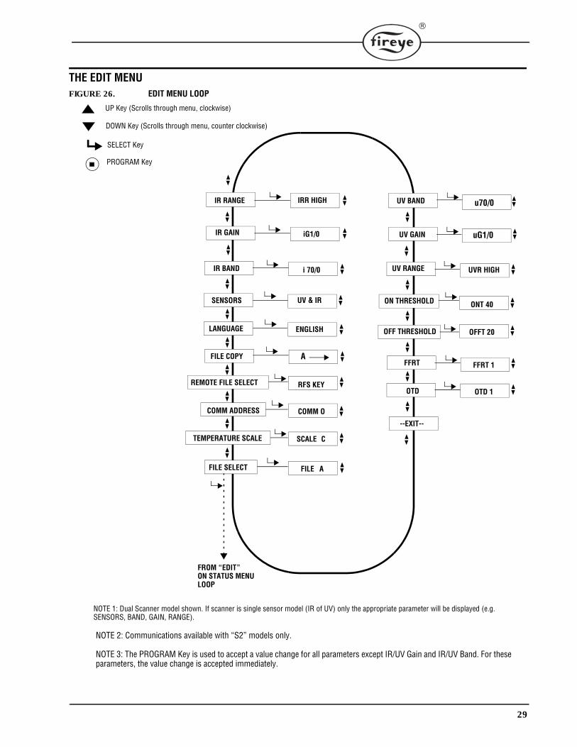
THE EDIT MENUFIGURE 26. EDIT MENU LOOP
P
SELECT Key
PROGRAM Key
UP Key (Scrolls through menu, clockwise)
DOWN Key (Scrolls through menu, counter clockwise)
IR RANGE
IR GAIN
IR BAND
SENSORS
LANGUAGE
FILE COPY
REMOTE FILE SELECT
COMM ADDRESS
TEMPERATURE SCALE
FILE SELECT
IRR HIGH
iG1/0
i 70/0
UV & IR
ENGLISH
A
RFS KEY
COMM O
SCALE C
FILE A
UV BAND
UV GAIN
UV RANGE
ON THRESHOLD
OFF THRESHOLD
FFRT
OTD
u70/0
uG1/0
UVR HIGH
ONT 40
OFFT 20
FFRT 1
OTD 1
FROM “EDIT”ON STATUS MENULOOP
--EXIT--
NOTE 1: Dual Scanner model shown. If scanner is single sensor model (IR of UV) only the appropriate parameter will be displayed (e.g. SENSORS, BAND, GAIN, RANGE).
NOTE 2: Communications available with “S2” models only.
NOTE 3: The PROGRAM Key is used to accept a value change for all parameters except IR/UV Gain and IR/UV Band. For these parameters, the value change is accepted immediately.
30
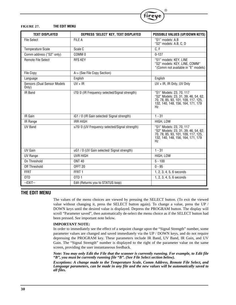
FIGURE 27. THE EDIT MENU
THE EDIT MENUThe values of the menu choices are viewed by pressing the SELECT button. (To exit the viewedvalue without changing it, press the SELECT button again). To change a value, press the UP /DOWN keys until the desired value is displayed. Depress the PROGRAM button. The display willscroll “Parameter saved”, then automatically de-select the menu choice as if the SELECT button hadbeen pressed. See important note below.
IMPORTANT NOTE:In order to immediately see the effect of a setpoint change upon the “Signal Strength” number, someparameter values are changed and saved immediately via the UP / DOWN keys, and do not requiredepressing the PROGRAM key. These parameters include IR Band, UV Band, IR Gain, and UVGain. The “Signal Strength” number is displayed to the right of the parameter value on the samescreen, providing the user instantaneous feedback.
Note: You may only Edit the File that the scanner is currently running. For example, to Edit file“B”, you must be currently running file “B”. (See File Select section below).Exceptions: A change made to the Temperature Scale, Comm Address, Remote File Select, andLanguage parameters, can be made in any file and the new values will be automatically saved toall files.
TEXT DISPLAYED DEPRESS ‘SELECT’ KEY, TEXT DISPLAYED POSSIBLE VALUES (UP/DOWN KEYS)
File Select FILE A “S1” models: A.B“S2” models: A.B, C, D
Temperature Scale Scale C C, F
Comm address (“S2” only) COMM 0 0-127
Remote File Select RFS KEY “S1” models: KEY, LINE“S2” models: KEY, LINE, COMM**(Comm not available in “E” models)
File Copy A-> (See File Copy Section)
Language English English
Sensors (Dual Sensor Models Only)
UV + IR UV + IR, IR Only, UV Only
IR Band i70/ 0 (IR Frequency selected/Signal strength) “S1” Models: 23, 70, 117“S2” Models: 23, 31, 39, 46, 54, 62, 70, 78, 85, 93, 101, 109, 117, 125, 132, 140, 148, 156, 164, 171, 179 Hz
IR Gain iG1 / 0 (IR Gain selected/ Signal strength) 1 - 31
IR Range IRR HIGH HIGH, LOW
UV Band u70/ 0 (UV Frequency selected/Signal strength) “S1” Models: 23, 70, 117“S2” Models: 23, 31, 39, 46, 54, 62, 70, 78, 85, 93, 101, 109, 117, 125, 132, 140, 148, 156, 164, 171, 179 Hz
UV Gain uG1 / 0 (UV Gain selected/ Signal strength) 1 - 31
UV Range UVR HIGH HIGH, LOW
On Threshold ONT 40 5 - 100
Off Threshold OFFT 20 0 - 95
FFRT FFRT 1 1, 2, 3, 4, 5, 6 seconds
OTD OTD 1 1, 2, 3, 4, 5, 6 seconds
--EXIT-- Edit (Returns you to STATUS loop)

31
File Select
The user can manually choose which file to run (and to Edit) by selecting this menu choice providedthe Remote File Select “KEY” choice is selected (see below). If the user wants to Edit the contents ofa file, they must first select and run that particular file. (See “exceptions” in note above).
Temperature Scale(Affects all files)
The scale may be selected to be Fahrenheit “F”, or Celsius “C”.
Comm Address (“S2” Models Only)(Affects all files)
The communications address selected may range from 0 to 127. Each scanner must have a uniqueaddress. No two scanners in a communications loop can have the same address.
Remote File Select(Affects all files)
Choices are KEY, LINE, COMM*
KEY allows the file selection to be made only at the scanner keypad (See File Select menu choice above).LINE allows the file selection to be made only via an external switch or relay.COMM allows the file selection to be made only via an external computer running Fireye Software.This feature is only available with FM & UL approved “S2” models. This feature is not availablewith CE approved “S2E” models.
FileCopy
This function allows the user to copy the contents of one internal scanner file to another. “S1” Models have two user configurable files, “A,B”, plus two factory configured files, “F1, F2”. “S2” Models add two additional user files, “C, D”.
Refer to “FILE COPY INSTRUCTIONS” for details.
Language(Affects all files)
This allows the user to select which language the menu system will use. The available choice is“English”.
Sensors (dual sensor units only, Type 95DS)
Choices include: UV only, IR only, or UV+IRThis parameter is used to manually select which sensor(s) are used in a particular file.
IR Band
The display is broken into two halves. The left side displays the selected IR flicker frequency (band-pass). The right side displays the signal strength attributed to the IR sensor.
For example with a model “S2” scanner, “i 23 / 80” indicates that 23Hz is selected and the currentsignal strength is 80 (as viewed in the Status loop).
Frequency choices range from 23Hz to 179Hz (“S2” models), or from 23Hz, 70Hz, 117Hz (“S1”models). The signal strength number can range from 0-999.
Note: Remember that while the signal strength number can range to 999, the “Flame Quality” num-ber viewed in the Status menu is capped at 100. In dual sensor models the “Flame Quality” numberis the sum of the IR and UV sensor signal strengths, capped at 100.
Pressing the UP and DOWN keys changes the frequency displayed and immediately stores the value(pressing the PROGRAM key is not required). The user will immediately see the effect on the signalstrength number displayed on the right side of the display.
32
IR Gain
The display is broken into two halves. The left side displays the selected IR Gain. The right half dis-plays the signal strength attributed to the IR sensor.
The IR sensor Gain is selectable from 1 (lowest) to 31 (highest). The signal strength number canrange from 0-999.
Note: Remember that while the signal strength number can range to 999, the “Flame Quality” num-ber viewed in the Status menu is capped at 100. In dual sensor models the “Flame Quality” numberis the sum of the IR and UV sensor signal strengths, capped at 100.
Pressing the UP and DOWN keys changes the IR Gain displayed and immediately stores the value(pressing the PROGRAM key is not required). The user will immediately see the effect on the signalstrength number displayed on the right side of the display. See MANUAL ADJUSTMENT note atthe end of this section.
IR Range
There are two selectable internal “ranges” for the IR sensor Gain, “High” and “Low”. If, when“Aiming” the scanner, a flashing IR number is observed, then the signal is over-range and the“Range” should be set to “LOW”. If, when “Aiming” the scanner, an IR number of less than 10 isobserved, then the gain Range should be set to “HIGH”. Refer to application note on page 36.
UV Band
The display is broken into two halves. The left side displays the selected UV flicker frequency(bandpass). The right side displays the signal strength attributed to the UV sensor.
For example with a model “S2” scanner, “u 23 / 80” indicates that 23Hz is selected and the currentsignal strength is 80 (as viewed in the Status loop).
Frequency choices range from 23Hz to 179Hz (“S2” models), or from 23Hz, 70Hz, 117Hz (“S1”models). The signal strength number can range from 0-999.
Note: Remember that while the signal strength number can range to 999, the “Flame Quality” num-ber viewed in the Status menu is capped at 100. In dual sensor models the “Flame Quality” numberis the sum of the IR and UV sensor signal strengths, capped at 100.
Pressing the UP and DOWN keys changes the frequency displayed and immediately stores the value(pressing the PROGRAM key is not required). The user will immediately see the effect on the signalstrength number displayed on the right side of the display.
UV Gain
The display is broken into two halves. The left side displays the selected UV Gain. The right half dis-plays the signal strength attributed to the UV sensor.The UV sensor Gain is selectable from 1(lowest) to 31(highest). The signal strength number canrange from 0-999.
Note: Remember that while the signal strength number can range to 999, the “Flame Quality” num-ber viewed in the Status menu is capped at 100. In dual sensor models the “Flame Quality” numberis the sum of the IR and UV sensor signal strengths, capped at 100.
Pressing the UP and DOWN keys changes the UV Gain displayed and immediately stores the value(pressing the PROGRAM key is not required). The user will immediately see the effect on the signalstrength number displayed on the right side of the display. See MANUAL ADJUSTMENT note atthe end of this section.
UV Range
There are two selectable internal “ranges” for the UV sensor Gain, “High” and “Low”. If, when“Aiming” the scanner, a flashing UV number is observed, then the signal is over-range and the“Range” should be set to “LOW”. If, when “Aiming” the scanner, a UV number of less than 10 isobserved, then the gain Range should be set to “HIGH”. Refer to application note on page 36.
33
On Threshold
This refers to the “pull-in” threshold of the internal Flame Relay, in terms of “Flame Quality”. TheON Threshold can be set from 5 to 100. The ON Threshold must be at least 5 units higher than theOFF Threshold.When the Flame Quality is equal to or greater than the ON Threshold (for a time equal to the “OnTime Delay setting, see below), the flame relay will energize.
Off Threshold
This refers to the “drop-out” threshold of the internal Flame Relay, in terms of “Flame Quality”. TheOFF Threshold can be set from 0 to 95. The OFF Threshold must be at least 5 units lower than theON Threshold.When the Flame Quality is equal to or less than the OFF Threshold (for a time equal to the “FlameFailure Response Time” setting, see below), the flame relay will de-energize.
FFRT
When the Flame Quality drops to or below the Flame Relay OFF Threshold, the Flame relay will de-energize after the selected Flame Failure Response Time (FFRT). The choices range from 1 to 6 sec-onds. The maximum allowable FFRT setting is determined by local safety code, and is factoryselected at 1 second.
OTD
When the Flame Quality rises to or above the Flame Relay ON Threshold, the Flame relay will ener-gize after the selected On Time Delay (OTD). The choices, range from 1 to 6 seconds.
--EXIT--
Pressing the SELECT key will return the user to the “Edit” display in the Status menu.
FILE COPY INSTRUCTIONSEXAMPLE:This function allows the user to copy the contents of one internal scanner file to another. “S1” Mod-els have two user configurable files, “A, B”, plus two factory configured files, “F1, F2”. “S2” Mod-els add two additional user files, “C, D”.
You may copy from any file to a user file. You are not allowed to copy from a user file to a factoryfile. You must first enter the source file, then the destination file.
The Factory Configured Files (“F1” and “F2”) contain factory default settings.
In File “F1”, the sensor gain is set at maximum (31) and the flicker frequency is set at 23 Hz. Atthese settings the scanner will respond to flame but will not likely discriminate between the targetflame and other nearby flames.
In File “F2”, the sensor gain is set at minimum (1) and the flicker frequency is set at 70 Hz. Atthese settings the scanner will not likely respond to flame until the scanner gain is increased.
Note: As shipped, all user files (A, B, C, D) contain the same setpoints as factory file “F2”.EXAMPLE:
With “FileCopy” displayed (EDIT menu), depress the SELECT key. The display will read “AÔ”with “A” being the source file. Use the UP/DOWN keys to select a different source file if desired.
With the desired source file displayed, press the PROGRAM key. The arrow will flash and the desti-nation file will appear (e.g. “A Ô A”). Initially the destination is displayed is “A”. Use the UP/DOWN keys to select the desired destination file (e.g. “A Ô B”).
Press the PROGRAM key to copy the source file to the destination file. The display will read “FileCopied”. (Pressing the SELECT key at any time before pressing the PROGRAM key for the secondtime will cancel the operation).
Press the UP/DOWN keys to scroll through the EDIT loop.
34
Manual Adjustment of IR or UV Gain
When manually adjusting the IR and / or UV “Gain” in the EDIT loop, the display will show both theselected gain (1-31), and the Signal Strength (Sensor Flame Quality) number (0-999) associated witheither the IR or UV sensor, e.g. “iG30 / 80”, “uG12 / 40”. (In this case, the total Flame Quality is“120”, and the FQ number viewed in the Status loop would be 100 [capped at 100]).
Each increment of the gain will increase the Signal Strength (Sensor Flame Quality) number for theselected sensor by 50%. In the above example, changing the UV sensor gain from 12 to 13 wouldincrease the UV Signal Strength from 40 to 60. Decreasing the IR sensor gain from 30 to 29 woulddecrease the IR Signal Strength from 80 to 53. (In this case, the total Flame Quality is “113”, and theFQ number as viewed in the Status loop would be 100 [capped at 100]).
For best scanner operation, the total Flame ON Signal Strength (IR Signal Strength + UV Signal Strength) should be between 100 and 150 or higher even though the Flame Quality display (Status Loop) is capped at 100.
35
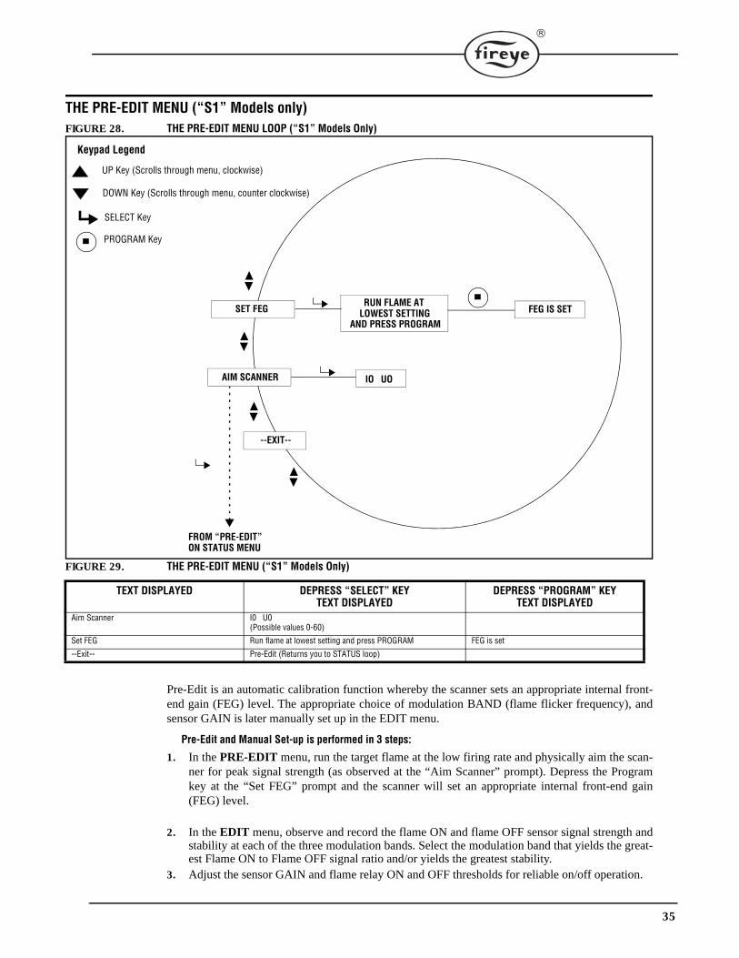
THE PRE-EDIT MENU (“S1” Models only)FIGURE 28. THE PRE-EDIT MENU LOOP (“S1” Models Only)
FIGURE 29. THE PRE-EDIT MENU (“S1” Models Only)
Pre-Edit is an automatic calibration function whereby the scanner sets an appropriate internal front-end gain (FEG) level. The appropriate choice of modulation BAND (flame flicker frequency), andsensor GAIN is later manually set up in the EDIT menu.
Pre-Edit and Manual Set-up is performed in 3 steps:
1. In the PRE-EDIT menu, run the target flame at the low firing rate and physically aim the scan-ner for peak signal strength (as observed at the “Aim Scanner” prompt). Depress the Programkey at the “Set FEG” prompt and the scanner will set an appropriate internal front-end gain(FEG) level.
2. In the EDIT menu, observe and record the flame ON and flame OFF sensor signal strength andstability at each of the three modulation bands. Select the modulation band that yields the great-est Flame ON to Flame OFF signal ratio and/or yields the greatest stability.
3. Adjust the sensor GAIN and flame relay ON and OFF thresholds for reliable on/off operation.
TEXT DISPLAYED DEPRESS “SELECT” KEYTEXT DISPLAYED
DEPRESS “PROGRAM” KEYTEXT DISPLAYED
Aim Scanner I0 U0(Possible values 0-60)
Set FEG Run flame at lowest setting and press PROGRAM FEG is set
--Exit-- Pre-Edit (Returns you to STATUS loop)
--EXIT--
FROM “PRE-EDIT”ON STATUS MENU
SET FEG
AIM SCANNER
RUN FLAME AT LOWEST SETTING
AND PRESS PROGRAMFEG IS SET
IO UO
SELECT Key
PROGRAM Key
UP Key (Scrolls through menu, clockwise)
Keypad Legend
DOWN Key (Scrolls through menu, counter clockwise)
36
Aim Scanner
When SELECT is depressed, “Ix Ux” is displayed (dual sensor models). The value of “x” may rangefrom 0 to 60. The value displayed represents the flame flicker intensity of the flame for the entireflicker frequency spectrum as individually sensed by the UV (U) sensor and/or IR (I) sensor(s).
The numbers should be at their peak (highest numerically) when the scanner is aimed at the primarycombustion zone (first 1/3) of the flame. If the scanner is equipped with both an IR and UV sensor,priority should be given to maximizing the UV intensity.
Run the flame at low fire rate and observe the signal intensity.
Physically aim the scanner at the first 1/3 of the flame to maximize the intensity reading. (Allow thescanner reading to stabilize two seconds after each movement.)
If the reading is l0 or less, the intensity is marginal. Verify that the appropriate sensor “Range”parameter (IR Range or UV Range) in the Edit menu is set to “HIGH”.
If the reading is greater than 26 (the number will blink) the signal is excessive. Verify that the appro-priate sensor “Range” parameter (IR Range or UV Range) in the Edit menu is set to “LOW”.
Application Note: In rare applications where the flame is extremely bright, it is possible to satu-rate the sensor. The symptom could be a very low signal, an erratic signal, or no signal at all. Ifthis situation is suspected, the installation of a sight-pipe orifice (kit P/N 53-121) is recom-mended.
Set FEG
Run the flame at low fire and press the PROGRAM button. The scanner will set an appropriate inter-nal front-end gain (FEG) level based upon the flame intensity (brightness) then display “FEG is set”.
--EXIT--
Pressing the SELECT key will return the user to the “Pre-Edit” menu choice of the main statusmenu.
Manual Set-up in Edit menu (“S1” Models only)In the EDIT menu with the target flame ON (at low fire), observe and record the sensor signalstrength and stability at each of the three modulation BANDS: 23, 70, and 117 Hz. The signalstrength display has a range of 0-999.
During set-up it may be necessary to adjust the sensor GAIN in order to keep the signal strengthvalue on scale. If so, observe and record the sensor GAIN value (1-31) selected.
With dual sensor models, perform this step for each sensor.
In the EDIT menu with the target flame OFF (leaving other burners firing), observe and recordthe sensor signal strength and stability at each of the three modulation BANDS: 23, 70, and 117 Hz.Do not adjust the sensor GAIN at this time.
With dual sensor models, perform this step for each sensor.
At each of the three modulation frequencies, compare the recorded Flame ON signal strengthto the recorded Flame OFF signal strength. Select the modulation BAND that yielded the greatestFlame ON to Flame OFF signal ratio and/or yielded the greatest stability.
With dual sensor models, perform this step for each sensor.
Adjust the sensor gain (1-31) so that the flame ON signal strength is well above the flame relay ONthreshold, and the flame OFF signal strength is well below the flame relay OFF threshold (see“Flame Relay Thresholds” on following page).
When manually adjusting the IR and / or UV “Gain” in the EDIT loop, the display will show both theselected gain (1-31), and the Signal Strength (Sensor Flame Quality) number (0-999) associated witheither the IR or UV sensor, e.g. “iG30 / 80”, “uG12 / 40”. (In this case, the total Flame Quality is“120”, and the FQ number viewed in the Status loop would be 100 [capped at 100]).

37
Each increment of the gain will increase the Signal Strength (Sensor Flame Quality) number for theselected sensor by 50%. In the above example, changing the UV sensor gain from 12 to 13 wouldincrease the UV Signal Strength from 40 to 60. Decreasing the IR sensor gain from 30 to 29 woulddecrease the IR Signal Strength from 80 to 53. (In this case, the total Flame Quality is “113”, and theFQ number as viewed in the Status loop would be 100 [capped at 100]).
For best scanner operation, the total Flame ON Signal Strength (IR Signal Strength + UV Signal Strength) should be between 100 and 150 or higher even though the Flame Quality dis-play (Status loop) is capped at 100.
Example:At the selected BAND the Flame ON signal ranged from 800 to 999, and the Flame OFF signalranged from 50 to 130 (a 6:1 on/off ratio).The user must reduce the sensor gain so that flame ON signal strength is well above the flame relayON threshold (factory programmed at 40), and the flame OFF signal strength is well below the flamerelay OFF threshold (factory programmed at 20).In this example, the user may reduce the gain to have a flame OFF signal of 0, and a flame ON signalof 150.
Special Note for Dual Sensor Models:With dual sensor models, the flame relay and 4-20 mA output will operate on the SUM of both theIR and UV signals. When setting the final GAIN adjustments, the user should favor the sensor (IR orUV) which exhibited the greatest flame ON:OFF signal ratio, and/or greatest stability.If the user chooses to use the input from only one sensor and disable the input from the other, he maydo so by selecting “IR ONLY” or “UV ONLY” as Sensors in the Edit menu.
Flame Relay Thresholds
The flame relay has a factory programmed FLAME ON threshold of 40, and a FLAME OFF thresh-old of 20 (0-100 scale). With these settings, it is recommended that the flame ON signal normally beat least 150. Other on and off thresholds may be selected to suit particular applications.
CAUTION: After selecting Sensor TYPE, Sensor BAND, Sensor GAIN, and Flame RelayON & OFF Thresholds, proper flame detection and flame discrimination must be verifiedby starting and stopping the burner several times. The flame relay must reliably de-energizefor all flame out conditions. This testing should be done with various adjacent burners onand off, and at various load levels. This is a requirement for proper operation.
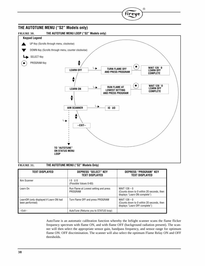
38
THE AUTOTUNE MENU (“S2” Models only) FIGURE 30. THE AUTOTUNE MENU LOOP (“S2” Models only)
FIGURE 31. THE AUTOTUNE MENU (“S2” Models Only)
AutoTune is an automatic calibration function whereby the InSight scanner scans the flame flickerfrequency spectrum with flame ON, and with flame OFF (background radiation present). The scan-ner will then select the appropriate sensor gain, bandpass frequency, and sensor range for optimumflame ON: OFF discrimination. The scanner will also select the optimum Flame Relay ON and OFFthresholds.
TEXT DISPLAYED DEPRESS “SELECT” KEYTEXT DISPLAYED
DEPRESS “PROGRAM” KEYTEXT DISPLAYED
Aim Scanner I 0 U 0(Possible Values 0-60)
Learn On Run Flame at Lowest setting and press PROGRAM
WAIT 128 – 0(Counts down to 0 within 20 seconds, then displays “Learn ON complete“)
LearnOff (only displayed if Learn ON had been performed)
Turn Flame OFF and press PROGRAM WAIT 128 – 0(Counts down to 0 within 20 seconds, then displays “Learn OFF complete”)
--Exit-- AutoTune (Returns you to STATUS loop)
--EXIT--
TO “AUTOTUNE”ON STATUS MENULOOP
LEARN OFF
LEARN ON
AIM SCANNER
TURN FLAME OFFAND PRESS PROGRAM
RUN FLAME AT LOWEST SETTING
AND PRESS PROGRAM
LEARN OFF COMPLETE
IO UO
SELECT Key
PROGRAM Key
UP Key (Scrolls through menu, clockwise)
Keypad Legend
DOWN Key (Scrolls through menu, counter clockwise)
WAIT 128 ‘ 0
LEARN OFF COMPLETE
WAIT 128 ‘ 0
39
AutoTune is performed in 3 steps:
1. Run the target flame at the low firing rate. Enter the AutoTune menu loop, press the UP key until“AIM SCANNER” is displayed then press SELECT. Physically aim the scanner for peak signalstrength as described in the “Aim Scanner” section below. Press the UP key when complete.
2. Press the UP key until “LEARN ON” is displayed then press SELECT. Press PROGRAM and thescanner will memorize the flame ON condition as described in the “Learn ON” section below. Pressthe UP key when complete.
3. Turn the target flame off. Press the UP key until “LEARN OFF” is displayed then press SELECT.Press PROGRAM and the scanner will memorize the flame OFF condition as described in the “LearnOFF” section below. Press the UP key when complete.
Aim Scanner
Scroll to “AIM SCANNER” and press the SELECT key.When SELECT is depressed, “Ix Ux” is displayed (dual sensor models). The value of “x” may range from0 to 60. The value displayed represents the flame flicker intensity of the flame for the entire flicker fre-quency spectrum as individually sensed by the UV (U) sensor and/or IR (I) sensor(s).The numbers should be at their peak (highest numerically) when the scanner is aimed at the primary com-bustion zone (first 1/3) of the flame. If the scanner is equipped with both an IR and UV sensor, priorityshould be given to maximizing the UV intensity.
Run the flame at low fire rate and observe the signal intensity.
Physically aim the scanner at the first 1/3 of the flame to maximize the intensity reading. (Allow the scan-ner reading to stabilize two seconds after each movement).
If the reading is l0 or less, the intensity is marginal. Verify that the appropriate sensor “Range” parameter(IR Range or UV Range) in the Edit menu is set to “HIGH”.
If the reading is greater than 26 (the number will blink) the signal is excessive. Verify that the appropriatesensor “Range” parameter (IR Range or UV Range) in the Edit menu is set to “LOW”.
When scanner is properly aimed, press the UP key.
Application Note: In rare applications where the flame is extremely bright, it is possible to saturatethe sensor. The symptom could be a very low signal, an erratic signal, or no signal at all. If this situ-ation is suspected, the installation of a sight-pipe orifice kit (P/N 53-121) is recommended.
Learn ON
Scroll to “LEARN ON” and press the SELECT key.
Run the flame at low fire and press the PROGRAM button. The scanner will display “Wait” followed by anumber that will count down from 128 to 0 in about 20 seconds. This will temporarily store the spectrumof the monitored flame and the adjacent flames. The front-end gain number, used in the ON/OFF calcula-tion, will be stored at this time. Press the UP key when complete.
Learn OFF
Scroll to “LEARN OFF” and press the SELECT key.
Turn off the monitored flame leaving adjacent flames operating, then press the PROGRAM button. Thescanner will display “Wait” followed by a number that will count down from 128 to 0 in about 20 seconds.This will temporarily store the spectrum of the adjacent flames.The “ON” spectrum will then be compared to the “OFF” spectrum and the frequency and gain for opti-mum discrimination will be selected.The IR and UV gain settings will be automatically selected based on the proportionality of their flameON: OFF ratios. (On dual sensor models, the contribution of the IR and UV signal strengths to the FlameQuality is also determined at this time by the selection of their respective gain numbers. The gain settingswill be selected to yield a total “signal strength” of between 100 and 150, which would yield a FlameQuality number of 100.The Flame relay ON and OFF thresholds will be automatically set to 40 and 20, respectively, unless the“off” signal level is exceptionally high, which usually indicates poor aiming of the scanner.
Note: If after learning flame OFF, an insufficient on/off ratio is not found in at least one sensor, the dis-play will show, “Warning: Poor discrimination, try re-aiming scanner”.
Press the UP key when complete.
--EXIT--
Pressing the SELECT key will return the user to the “AutoTune” menu choice of the main menu.
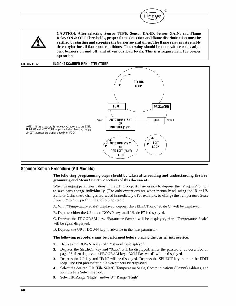
40
FIGURE 32. INSIGHT SCANNER MENU STRUCTURE
Scanner Set-up Procedure (All Models)The following programming steps should be taken after reading and understanding the Pro-gramming and Menu Structure sections of this document.
When changing parameter values in the EDIT loop, it is necessary to depress the “Program” buttonto save each change individually. (The only exceptions are when manually adjusting the IR or UVBand or Gain; these changes are saved immediately). For example, to change the Temperature Scalefrom “C” to “F”, perform the following steps:
A. With “Temperature Scale” displayed, depress the SELECT key. “Scale C” will be displayed.
B. Depress either the UP or the DOWN key until “Scale F” is displayed.
C. Depress the PROGRAM key. “Parameter Saved” will be displayed, then “Temperature Scale”will be again displayed.
D. Depress the UP or DOWN key to advance to the next parameter.
The following procedure may be performed before placing the burner into service:
1. Depress the DOWN key until “Password” is displayed.
2. Depress the SELECT key and “0xxx” will be displayed. Enter the password, as described onpage 27, then depress the PROGRAM key. “Valid Password” will be displayed.
3. Depress the UP key and “Edit” will be displayed. Depress the SELECT key to enter the EDITloop. The first parameter “File Select” will be displayed.
4. Select the desired File (File Select), Temperature Scale, Communications (Comm) Address, andRemote File Select method.
5. Select IR Range “High”, and/or UV Range “High”.
CAUTION: After selecting Sensor TYPE, Sensor BAND, Sensor GAIN, and FlameRelay ON & OFF Thresholds, proper flame detection and flame discrimination must beverified by starting and stopping the burner several times. The flame relay must reliablyde-energize for all flame out conditions. This testing should be done with various adja-cent burners on and off, and at various load levels. This is a requirement for properoperation.
FQ O PASSWORD
AUTOTUNE (“S2”) EDIT
LOOP
EDITLOOP
NOTE 1: If the password is not entered, access to the EDIT,PRE-EDIT and AUTO TUNE loops are denied. Pressing the (s)UP KEY advances the display directly to “FQ O”.
Note 1
STATUS LOOP
PRE-EDIT (“S1”)
AUTOTUNE (“S2”)
PRE-EDIT (“S1”)OR
ORNote 1
41
6. Select the desired Flame Failure Response Time (FFRT) and On-Time Delay (OTD).7. Depress the UP key until “-Exit-” is displayed.8. Depress the SELECT key to return to the status loop. (“Edit” will be displayed).
“S1” Models: The following procedure is performed with the burner operating (Review the“PRE-EDIT” section of this document).
1. Depress the UP key until “PRE-EDIT” is displayed. (Note: If “PRE-EDIT” is not displayed, itwill be necessary to re-enter the password).
2. With “PRE-EDIT” displayed, depress the SELECT key to enter the Pre-Edit menu. “Aim Scan-ner” will be displayed.
3. Depress the SELECT key and “Ix Ux” will be displayed. With the burner OFF, “x” will equalzero, i.e. “I0 U0”.
4. Place the burner in service (at low firing rate). Physically aim the scanner until the highest AIMnumbers are displayed. Secure the scanner in position, then depress the SELECT key. “AimScanner” will again be displayed. Refer to application note on page 39.
5. Depress the UP key until “SET FEG” is displayed.6. Depress the SELECT key and “Run flame at lowest setting and press PROGRAM” will be dis-
played.7. Depress the PROGRAM key and the scanner will display “FEG is SET”.8. Depress the SELECT key and “-EXIT-” is displayed.9. Depress the SELECT key to return to the Status menu. “PRE-EDIT” will be displayed.10. Depress the DOWN key and “EDIT” will be displayed.11. Depress the SELECT key to again enter the EDIT loop.12. Record the flame signal strength at each of the three modulation BANDS (23, 70, and 117 Hz)
as described in the “Manual Set-Up in Edit Menu” section on page 36.13. Turn the burner off and again record the flame signal strength at each of the three modulation
BANDS (23, 70, and 117 Hz).14. Select the BAND and GAIN where the greatest flame ON / flame OFF signal ratio occurs.15. Turn the burner ON then OFF again to verify proper detection and discrimination. If necessary,
you may further adjust the gain, or band, or enable or disable a sensor. For future reference, listthe final setpoints on the following Configuration Record.
“S2” Models: The following procedure is performed with the burner operating (Review the“AutoTune” section of this document).
1. Depress the UP key until “AutoTune” is displayed. (Note: If “AutoTune” is not displayed, it willbe necessary to re-enter the password).
2. With “AutoTune” displayed, depress the SELECT key to enter the AutoTune menu. “Aim Scan-ner” will be displayed.
3. Depress the SELECT key and “Ix Ux” will be displayed. With the burner OFF, “x” will equalzero, i.e. “I0 U0”.
4. Place the burner in service (at low firing rate). Physically aim the scanner until the highest AIMnumbers are displayed. Secure the scanner in position, then depress the SELECT key. “AimScanner” will again be displayed. Refer to application note on page 39.
5. Depress the UP key until “Learn ON” is displayed.6. Depress the SELECT key and “Run flame at lowest setting and press PROGRAM” will be dis-
played.7. Depress the PROGRAM key and the scanner will count down from 128 to 0 then display “Learn
ON complete”.8. Depress the SELECT key and “Learn ON” is again displayed.9. Depress the UP key and “Learn OFF” is displayed.10. Depress the SELECT key and “Turn flame OFF and press PROGRAM” will be displayed.11. Press the PROGRAM key (with the target burner turned OFF) and the scanner will count down
from 128 to 0, then display “Learn flame OFF complete”.12. Depress the UP key and “-EXIT-” is displayed.
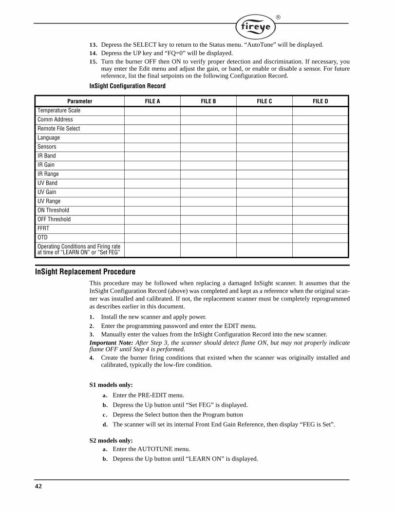
42
13. Depress the SELECT key to return to the Status menu. “AutoTune” will be displayed.14. Depress the UP key and “FQ=0” will be displayed.15. Turn the burner OFF then ON to verify proper detection and discrimination. If necessary, you
may enter the Edit menu and adjust the gain, or band, or enable or disable a sensor. For futurereference, list the final setpoints on the following Configuration Record.
InSight Replacement ProcedureThis procedure may be followed when replacing a damaged InSight scanner. It assumes that theInSight Configuration Record (above) was completed and kept as a reference when the original scan-ner was installed and calibrated. If not, the replacement scanner must be completely reprogrammedas describes earlier in this document.
1. Install the new scanner and apply power.
2. Enter the programming password and enter the EDIT menu.3. Manually enter the values from the InSight Configuration Record into the new scanner.Important Note: After Step 3, the scanner should detect flame ON, but may not properly indicateflame OFF until Step 4 is performed.4. Create the burner firing conditions that existed when the scanner was originally installed and
calibrated, typically the low-fire condition.
S1 models only:
a. Enter the PRE-EDIT menu.
b. Depress the Up button until “Set FEG” is displayed.
c . Depress the Select button then the Program button
d. The scanner will set its internal Front End Gain Reference, then display “FEG is Set”.
S2 models only: a. Enter the AUTOTUNE menu.
b. Depress the Up button until “LEARN ON” is displayed.
InSight Configuration Record
Parameter FILE A FILE B FILE C FILE D
Temperature Scale
Comm Address
Remote File Select
Language
Sensors
IR Band
IR Gain
IR Range
UV Band
UV Gain
UV Range
ON Threshold
OFF Threshold
FFRT
OTD
Operating Conditions and Firing rate at time of “LEARN ON” or “Set FEG”
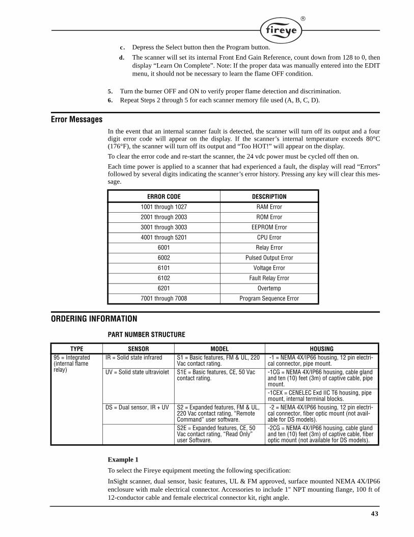
43
c . Depress the Select button then the Program button.
d. The scanner will set its internal Front End Gain Reference, count down from 128 to 0, thendisplay “Learn On Complete”. Note: If the proper data was manually entered into the EDITmenu, it should not be necessary to learn the flame OFF condition.
5. Turn the burner OFF and ON to verify proper flame detection and discrimination.6. Repeat Steps 2 through 5 for each scanner memory file used (A, B, C, D).
Error MessagesIn the event that an internal scanner fault is detected, the scanner will turn off its output and a fourdigit error code will appear on the display. If the scanner’s internal temperature exceeds 80°C(176°F), the scanner will turn off its output and “Too HOT!” will appear on the display.
To clear the error code and re-start the scanner, the 24 vdc power must be cycled off then on.
Each time power is applied to a scanner that had experienced a fault, the display will read “Errors”followed by several digits indicating the scanner’s error history. Pressing any key will clear this mes-sage.
ORDERING INFORMATION
PART NUMBER STRUCTURE
Example 1
To select the Fireye equipment meeting the following specification:
InSight scanner, dual sensor, basic features, UL & FM approved, surface mounted NEMA 4X/IP66enclosure with male electrical connector. Accessories to include 1" NPT mounting flange, 100 ft of12-conductor cable and female electrical connector kit, right angle.
ERROR CODE DESCRIPTION
1001 through 1027 RAM Error
2001 through 2003 ROM Error
3001 through 3003 EEPROM Error
4001 through 5201 CPU Error
6001 Relay Error
6002 Pulsed Output Error
6101 Voltage Error
6102 Fault Relay Error
6201 Overtemp
7001 through 7008 Program Sequence Error
TYPE SENSOR MODEL HOUSING95 = Integrated (internal flame relay)
IR = Solid state infrared S1 = Basic features, FM & UL, 220 Vac contact rating.
-1 = NEMA 4X/IP66 housing, 12 pin electri-cal connector, pipe mount.
UV = Solid state ultraviolet S1E = Basic features, CE, 50 Vac contact rating.
-1CG = NEMA 4X/IP66 housing, cable gland and ten (10) feet (3m) of captive cable, pipe mount. -1CEX = CENELEC Exd IIC T6 housing, pipe mount, internal terminal blocks.
DS = Dual sensor, IR + UV S2 = Expanded features, FM & UL, 220 Vac contact rating, “Remote Command” user software.
-2 = NEMA 4X/IP66 housing, 12 pin electri-cal connector, fiber optic mount (not avail-able for DS models).
S2E = Expanded features, CE, 50 Vac contact rating, “Read Only” user Software.
-2CG = NEMA 4X/IP66 housing, cable gland and ten (10) feet (3m) of captive cable, fiber optic mount (not available for DS models).
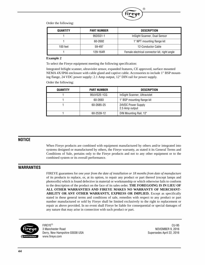
44
Order the following:
Example 2
To select the Fireye equipment meeting the following specification:
Integrated InSight scanner, ultraviolet sensor, expanded features, CE approved, surface mounted NEMA 4X/IP66 enclosure with cable gland and captive cable. Accessories to include 1" BSP mount-ing flange, 24 VDC power supply: 2.1 Amp output, 12" DIN rail for power supply.
Order the following:
NOTICEWhen Fireye products are combined with equipment manufactured by others and/or integrated intosystems designed or manufactured by others, the Fireye warranty, as stated it its General Terms andConditions of Sale, pertains only to the Fireye products and not to any other equipment or to thecombined system or its overall performance.
WARRANTIESFIREYE guarantees for one year from the date of installation or 18 months from date of manufactureof its products to replace, or, at its option, to repair any product or part thereof (except lamps andphotocells) which is found defective in material or workmanship or which otherwise fails to conformto the description of the product on the face of its sales order. THE FOREGOING IS IN LIEU OFALL OTHER WARRANTIES AND FIREYE MAKES NO WARRANTY OF MERCHANT-ABILITY OR ANY OTHER WARRANTY, EXPRESS OR IMPLIED. Except as specificallystated in these general terms and conditions of sale, remedies with respect to any product or partnumber manufactured or sold by Fireye shall be limited exclusively to the right to replacement orrepair as above provided. In no event shall Fireye be liable for consequential or special damages ofany nature that may arise in connection with such product or part.
QUANTITY PART NUMBER DESCRIPTION
1 95DSS1-1 InSight Scanner, Dual Sensor
1 60-2692 1" NPT mounting flange kit
100 feet 59-497 12-Conductor Cable
1 129-164R Female electrical connector kit, right angle
QUANTITY PART NUMBER DESCRIPTION
1 95UVS2E-1CG InSight Scanner, Ultraviolet
1 60-2693 1" BSP mounting flange kit
1 60-2685-25 24VDC Power Supply2.5 Amp output
1 60-2539-12 DIN Mounting Rail, 12"
FIREYE CU-953 Manchester Road NOVEMBER 9, 2016Derry, New Hampshire 03038 USA Supersedes April 22, 2016www.fireye.com