Embed Size (px)
Citation preview

FFBB
F. BLOCKNeue TechnikEntwicklungund Vertrieb
Model R
Operation manual
Processing unit for Flow switches
/-guards
Tribloc E - „R”- Processing unit
www.fblock.de
Karl-Carstens-Straße 12
D-52146 Würselen
Tel.: +49 - 2405 - 40 80 10 - 0
Fax.: +49 - 2405 - 40 80 10 - 10
FFBB
F. BLOCKNeue TechnikEntwicklungund Vertrieb
Table of contents:
1 Features and application 3
2 Installation & wiring 4
3 Indicators at the processing unit 6
- LED Operation 6
- Level indicator 6
- LED Relay 6
- LED Test 6
4 e zation interface 7
5 erization 8
7a Paramet ri
9 Contact F. Block 20
Paramet ri
Paramet
- Amplification 8
- Threshold 8
- Damping 9
- DIP switches 9
6 Current loop (optional) 10
e zation utilizing the programming device 11
- Adjustment to a given sensor 13
7b Parameterization utilizing a PC 14
8 Adjustment of the Tribloc system to the conveying situation 15
Page 3
1 Features and application
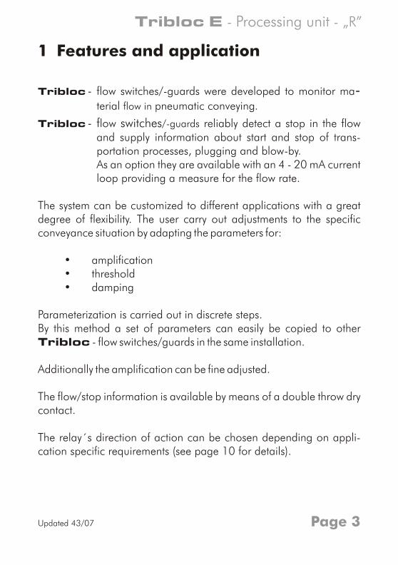
Tribloc - flow switches/-guards were developed to monitor ma-terial flow in pneumatic conveying.
Tribloc - flow switches/-guards reliably detect a stop in the flow and supply information about start and stop of trans-portation processes, plugging and blow-by.As an option they are available with an 4 - 20 mA current loop providing a measure for the flow rate.
The system can be customized to different applications with a great degree of flexibility. The user carry out adjustments to the specific conveyance situation by adapting the parameters for:
• amplification• threshold• damping
Parameterization is carried out in discrete steps.By this method a set of parameters can easily be copied to other Tribloc - flow switches/guards in the same installation.
Additionally the amplification can be fine adjusted.
The flow/stop information is available by means of a double throw dry contact.
The relay´s direction of action can be chosen depending on appli-cation specific requirements (see page 10 for details).
Tribloc E - „R”- Processing unit
Updated 43/07
2 Installation & wiring
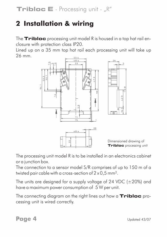
The Tribloc processing unit model R is housed in a top hat rail en-closure with protection class IP20.Lined up on a 35 mm top hat rail each processing unit will take up26 mm.
The processing unit model R is to be installed in an electronics cabinet or a junction box.The connection to a sensor model S/R comprises of up to 150 m of a twisted pair cable with a cross-section of 2 x 0,5 mm².
The units are designed for a supply voltage of 24 VDC (±20%) and have a maximum power consumption of 5 W per unit.
The connecting diagram on the right lines out how a Tribloc pro-cessing unit is wired correctly.
Dimensioned drawing ofTribloc processing unit
Page 4
Tribloc E - - „R”Processing unit
Updated 43/07
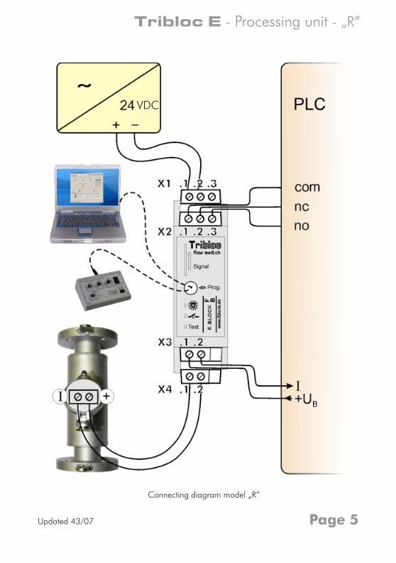
Connecting diagram model „R”
Page 5
Tribloc E - - „R”Processing unit
VDC
Updated 43/07
3 Indicators at the processing unit
LED
all LEDs
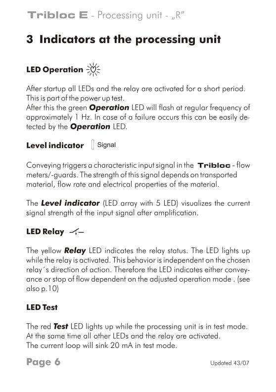
After this the green Operation will flash at regular frequency of approximately 1 Hz. In case of a failure occurs this can be easily detected by the Operation LED.
Level indicator
LED
Operation
After startup and the relay are activated for a short period.This is part of the power up test.
LED -
Conveying triggers a characteristic input signal in the Tribloc - flow meters/-guards. The strength of this signal depends on transportedmaterial, flow rate and electrical properties of the material.
The Level indicator (LED array with 5 LED) visualizes the currentsignal strength of the input signal after amplification.
Relay
The yellow Relay LED indicates the relay status. The LED lights up while the relay is activated. This behavior is independent on the chosen relay´s direction of action. Therefore the LED indicates either convey-ance or stop of flow dependent on the adjusted operation mode . (see also p.10)
LED Test
The red Test LED lights up while the processing unit is in test mode.At the same time all other LEDs and the relay are activated.The current loop will sink 20 mA in test mode.
Signal
Page 6
Tribloc E - „R”- Processing unit
Updated 43/07
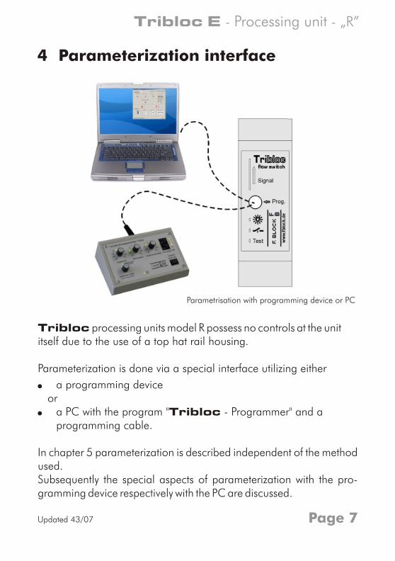
Tribloc processing units model R possess no controls at the unititself due to the use of a top hat rail housing.
Parameterization is done via a special interface utilizing either
! a programming device or! a PC with the program "Tribloc - Programmer" and a
programming cable.
In chapter 5 parameterization is described independent of the method used.Subsequently the special aspects of parameterization with the pro-gramming device respectively with the PC are discussed.
4 Parameterization interface
Parametrisation with programming device or PC
Page 7
Tribloc E - - „R”Processing unit
Updated 43/07
5 Parameterization
By means of three multiple position switches (each with positions 0 to 9) and can be adjusted.
DIP switch.Potentiometer allows a fine adjustment.
Amplification
With the Amplification switch the amplification of the signal can be adjusted.The signal strength is visualized by the 5 LEDs of the level indicator.The positions 0 to 9 of the switch correspond to an amplification of 1 to 10.
Threshold
With the Threshold switch the threshold of the device can be ad-justed.
The device will detect flow whenever the selected threshold is exceeded.
amplification, threshold dampingThe mode of operation can be selected with a quadruple A
Amplification fine
The potentiometer Amplification fine can be used to make several devices display exactly the same reading.
The positions 0 to 9 of the switch correspond to a threshold of 0 to 90%.
Page 8
Tribloc E - „R”- Processing unit
Updated 43/07
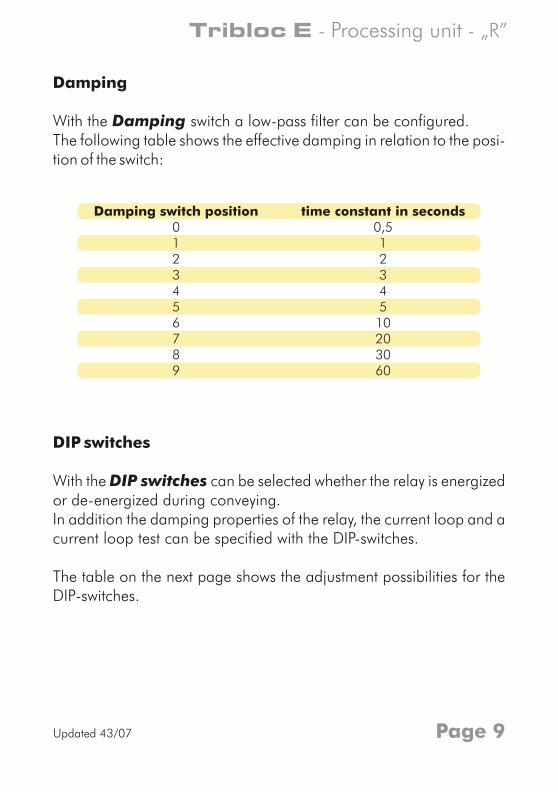
Damping
With the Damping switch a low-pass filter can be configured.The following table shows the effective damping in relation to the posi-tion of the switch:
DIP switches
With the DIP switches can be selected whether the relay is energizedor de-energized during conveying. In addition the damping properties of the relay, the current loop and acurrent loop test can be specified with the DIP-switches.
The table on the next page shows the adjustment possibilities for the DIP-switches.
Damping switch position time constant in seconds0123456789
0,512345
10203060
Page 9
Tribloc E - - „R” Processing unit
Updated 43/07
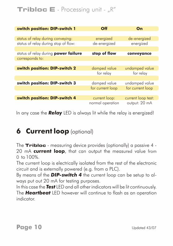
6 Current loop (optional)
The Tribloc - measuring device provides (optionally) a passive 4 - 20 mA current loop, that can output the measured value from
0 to 100%.The current loop is electrically isolated from the rest of the electroniccircuit and is externally powered (e.g. from a PLC).By means of the DIP-switch 4 the current loop can be setup to al-ways put out 20 mA for testing purposes. In this case the Test LED and all other indicators will be lit continuously.The Heartbeat LED however will continue to flash as an operation indicator.
In any case the Relay LED is always lit while the relay is energized!
switch position: DIP-switch 1 Off On
status of relay during conveying: energized de-energizedstatus of relay during stop of flow: de-energized energized
status of relay during stop of flow conveyancepower failurecorresponds to:
damped value undamped valueswitch position: DIP-switch 2for relay for relay
switch position: DIP-switch 3 damped value undamped valuefor current loop for current loop
switch position: DIP-switch 4 current loop: current loop test: normal operation output: 20 mA
Page 10
Tribloc E - „R”- Processing unit
Updated 43/07
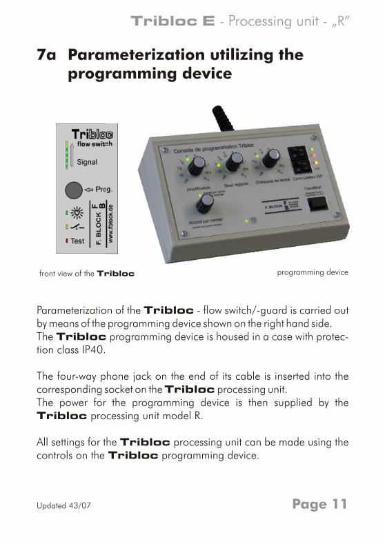
Parameterization of the Tribloc - flow switch/-guard is carried out by means of the programming device shown on the right hand side.The Tribloc programming device is housed in a case with protec-tion class IP40.
The four-way phone jack on the end of its cable is inserted into the corresponding socket on the Tribloc processing unit. The power for the programming device is then supplied by theTribloc processing unit model R.
All settings for the Tribloc processing unit can be made using thecontrols on the Tribloc programming device.
7a utilizing the programming device
Parameterization
front view of the Tribloc programming device
Page 11
Tribloc E - - „R” Processing unit
Updated 43/07
Verstärkung
Feinabgleich(drücken für Mittelstellung)
Schwelle DämpfungFeinabgleichMittelstellung
DIP-Schalter
Übernahme5s gedrückt halten für
Nullpunktabgleich( )
Tribloc-Programmiergerät
0
1
9
8
7
6
54
3
2
0
1
9
8
7
6
54
3
2
0
1
9
8
7
6
54
3
2
1
2
3
4
0 1
0 1
0 1
0 1
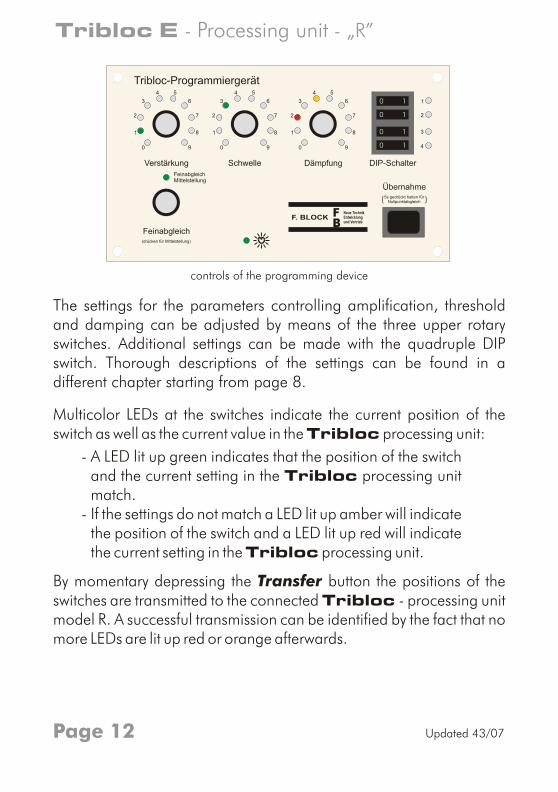
The settings for the parameters controlling amplification, threshold and damping can be adjusted by means of the three upper rotary switches. Additional settings can be made with the quadruple DIP switch. Thorough descriptions of the settings can be found in adifferent chapter starting from page 8.
Multicolor LEDs at the switches indicate the current position of theswitch as well as the current value in the Tribloc processing unit:
- A LED lit up green indicates that the position of the switch and the current setting in the Tribloc processing unit match.
- If the settings do not match a LED lit up amber will indicate the position of the switch and a LED lit up red will indicate the current setting in the Tribloc processing unit.
By momentary depressing the Transfer button the positions of the switches are transmitted to the connected Tribloc - processing unit model R. A successful transmission can be identified by the fact that no more LEDs are lit up red or orange afterwards.
controls of the programming device
Page 12
Tribloc E - - „R”Processing unit
Updated 43/07
amplification threshold damping
0
1
9
8
7
6
54
3
2
0
1
9
8
7
6
54
3
2
0
1
9
8
7
6
54
3
2
amplification threshold damping
0
1
9
8
7
6
54
3
2
0
1
9
8
7
6
54
3
2
0
1
9
8
7
6
54
3
2
amplification threshold damping
0
1
9
8
7
6
54
3
2
0
1
9
8
7
6
54
3
2
0
1
9
8
7
6
54
3
2
With the dial "Fine adjustment" the output of the current loop can be adjusted within a certain range. To get a medial position the dial can be pushed in. The medial position will be indicated by the LED located above the dial.
After approximately 3 minutes without operation of any control theTribloc programming device will enter a power save mode.In this mode all LEDs are off. Only the indictor will flash once every two seconds. As soon as any control is operated the device will return to normal operation.
Adjustment to a given sensor
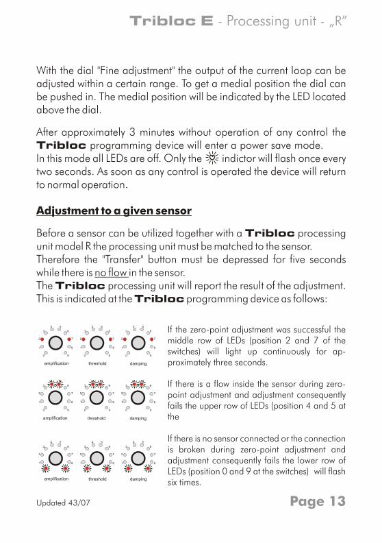
Before a sensor can be utilized together with a Tribloc processing unit model R the processing unit must be matched to the sensor.Therefore the "Transfer" button must be depressed for five seconds while there is no flow in the sensor.The Tribloc processing unit will report the result of the adjustment. This is indicated at the Tribloc programming device as follows:
If the zero-point adjustment was successful the middle row of LEDs (position 2 and 7 of the switches) will light up continuously for ap-proximately three seconds.
If there is a flow inside the sensor during zero-point adjustment and adjustment consequently fails the upper row of LEDs (position 4 and 5 at the
If there is no sensor connected or the connection is broken during zero-point adjustment and adjustment consequently fails the lower row of LEDs (position 0 and 9 at the switches) will flash six times.
Page 13
Tribloc E - - „R” Processing unit
Updated 43/07
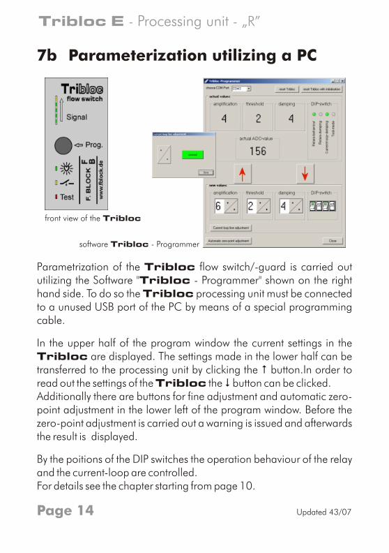
Parametrization of the Tribloc flow switch/-guard is carried out utilizing the Software "Tribloc - Programmer" shown on the right hand side. To do so the Tribloc processing unit must be connected to a unused USB port of the PC by means of a special programming cable.
In the upper half of the program window the current settings in the Tribloc are displayed. The settings made in the lower half can be transferred to the processing unit by clicking the # button.In order to read out the settings of the Tribloc the $ button can be clicked. Additionally there are buttons for fine adjustment and automatic zero-point adjustment in the lower left of the program window. Before the zero-point adjustment is carried out a warning is issued and afterwards the result is displayed.
By the poitions of the DIP switches the operation behaviour of the relay and the current-loop are controlled. For details see the chapter starting from page 10.
7b Parameterization utilizing a PC
front view of the Tribloc
software Tribloc - Programmer
Page 14
Tribloc E - - „R”Processing unit
Updated 43/07
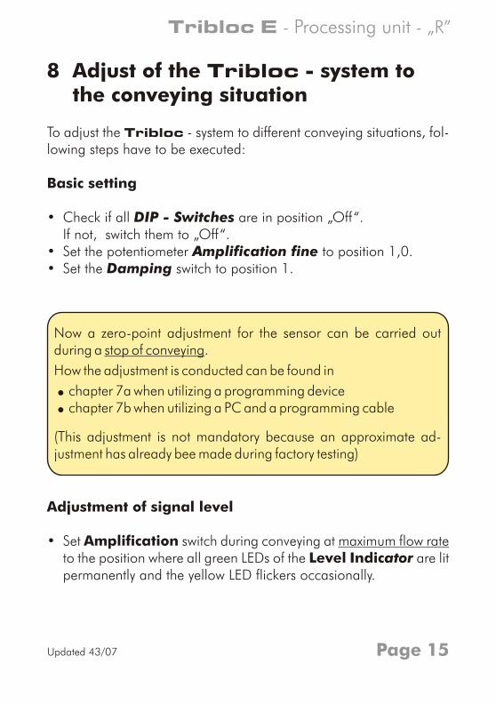
8 Adjust of the Tribloc - system to the conveying situation
To adjust the Tribloc - system to different conveying situations, fol-lowing steps have to be executed:
Basic setting
• Check if all DIP - Switches are in position „Off“.If not, switch them to „Off“.
• Set the potentiometer Amplification fine to position 1,0.• Set the Damping switch to position 1.
Adjustment of signal level
• Set Amplification switch during conveying at maximum flow rate to the position where all green LEDs of the Level Indicator are litpermanently and the yellow LED flickers occasionally.
Now a zero-point adjustment for the sensor can be carried out during a stop of conveying.
How the adjustment is conducted can be found in
! chapter 7a when utilizing a programming device! chapter 7b when utilizing a PC and a programming cable
(This adjustment is not mandatory because an approximate ad-justment has already bee made during factory testing)
Page 15
Tribloc E - - „R” Processing unit
Updated 43/07
Adjustment of the threshold for conveying
• Choose position 9 for Threshold
• Decrease the setting of the Threshold switch slowly from position9 until the relay is energized and the LED Relay is lit per-manently.
! If conveying can not be interrupted due to operational reasons the next step can be skipped and the proper function of the Tribloc system should be checked later at the next stop of conveying.
Adjustment of the threshold for stop of flow
• Now check if the relay is de-energized when conveying stops. If not, set the Threshold switch to next higher position.
! If the adjustment of threshold for stop and for conveying can not be carried out successfully with the same position of the Threshold switch restart with the step Adjustment of signal level and increase or decrease the position of the Amplification switch by one.
• Restart conveying
Time response / Damping
• Adjust the Damping switch to the desired value for damping. (refer to table on page 9)
Page 16
Tribloc E - - „R”Processing unit
Updated 43/07
Relay´s direction of action
• With the DIP switch 2 the direction of action for the relay can be set up.It can be selected whether the relay should be energized or de-en-ergized during conveying. With this setting the failsafe-behavior in case of a power loss can be controlled. (refer to table on page 10)
Additional settings
• With the DIP switch 2 can be selected whether the relay reacts to the damped or the undamped measured value.
• In the same way DIP switch 3 is used to select the damped or the undamped measured value for the output of the current loop.
• The DIP switch 4 is only for testing the current loop (see page 10) and must be in position "off" for normal operation.
! Because all adjustments are made in discrete steps it is possible to
transfer a configuration to other Tribloc processing units oper-ating at the same conveyance conditions.
Page 17
Tribloc E - - „R” Processing unit
Updated 43/07
Notes:
Page 18
Tribloc E - - „R”Processing unit
Updated 43/07
Notes:
Page 19
Tribloc E - - „R” Processing unit
Updated 43/07
FFBB
F. BLOCKNeue TechnikEntwicklungund Vertrieb
Contact:
F. Block
52146 Würselen Fax.: GermanyeMail: [email protected] Website: www.fblock.de
Karl-Carstens-Straße 12 Tel.: +49 - 2405 - 40 80 10 - 0+49 - 2405 - 40 80 10 - 10
Updated 43/07© 2007 F.Block Right of modification reserved, errors excepted.
Model R
Processing unit forFlow switches
-guards