Embed Size (px)
Citation preview
Model Q46 Modbus Communications
Manual
Home Office European Office Analytical Technology, Inc. ATI (UK) Limited 6 Iron Bridge Drive Unit 1 & 2 Gatehead Business Park Collegeville, PA19426 Delph New Road, Delph Saddleworth OL3 5DE Ph: 800-959-0299 Ph: +44 (0)1457-873-318 610-917-0991 Fax: 610-917-0992 Fax: + 44 (0)1457-874-468 Email: [email protected] Email:[email protected]

2 O&M Manual Rev-D (2/16)
PRODUCT WARRANTY Analytical Technology, Inc. (Manufacturer) warrants to the Customer that if any part(s) of the Manufacturer's equipment proves to be defective in materials or workmanship within the earlier of 18 months of the date of shipment or 12 months of the date of start-up, such defective parts will be repaired or replaced free of charge. Inspection and repairs to products thought to be defective within the warranty period will be completed at the Manufacturer's facilities in Collegeville, PA. Products on which warranty repairs are required shall be shipped freight prepaid to the Manufacturer. The product(s) will be returned freight prepaid and allowed if it is determined by the manufacturer that the part(s) failed due to defective materials or workmanship. This warranty does not cover consumable items, batteries, or wear items subject to periodic replacement including lamps and fuses. Gas sensors carry a 12 months from date of shipment warranty and are subject to inspection for evidence of misuse, abuse, alteration, improper storage, or extended exposure to excessive gas concentrations. Should inspection indicate that sensors have failed due to any of the above, the warranty shall not apply. The Manufacturer assumes no liability for consequential damages of any kind, and the buyer by acceptance of this equipment will assume all liability for the consequences of its use or misuse by the Customer, his employees, or others. A defect within the meaning of this warranty is any part of any piece of a Manufacturer's product which shall, when such part is capable of being renewed, repaired, or replaced, operate to condemn such piece of equipment. This warranty is in lieu of all other warranties ( including without limiting the generality of the foregoing warranties of merchantability and fitness for a particular purpose), guarantees, obligations or liabilities expressed or implied by the Manufacturer or its representatives and by statute or rule of law. This warranty is void if the Manufacturer's product(s) has been subject to misuse or abuse, or has not been operated or stored in accordance with instructions, or if the serial number has been removed. Analytical Technology, Inc. makes no other warranty expressed or implied except as stated above.
ATI Q46 Modbus Communications Manual
3
O&M Manual Rev-D (2/16)
Table of Contents
Part 1 – Modbus Description ____________________________________________________ 4
1.1 Modbus Technical Overview........................................................................................ 4 1.2 Modbus Connection .................................................................................................... 6 1.3 Registers and Coils ..................................................................................................... 7 1.4 RS-485 Communication .............................................................................................. 8 1.5 Cable Specification ...................................................................................................... 9 1.6 RS-485 Line Drivers/Receivers ................................................................................. 10 1.7 120 Ohm Termination ................................................................................................ 11 1.8 Bias ........................................................................................................................... 11 1.9 Drops ........................................................................................................................ 11 1.10 Daisy Chaining .......................................................................................................... 12 1.11 Shielding ................................................................................................................... 12 1.12 Slave Connection Detail ............................................................................................ 13 1.13 Q46 Register Assignment .......................................................................................... 14
Table of Figures
Figure 1 - Modbus Terminal Connections ........................................................................ 6 Figure 2 - Modbus Set-up Screen .................................................................................. 14 Figure 3 - Q46 Modbus Input Register Data .................................................................. 15 Figure 4 - Status Register Bitfield Flags ........................................................................ 16
Tables of Registers
Q46H/62, Q45H/63 or Q46H/79PR Residual Chlorine Tables ___________________ 17 Q46H/64 Dissolved Ozone Tables _______________________________________ 18 Q46H/65 Dissolved Chlorine Dioxide Tables ________________________________ 19 Q46P & Q46R pH and ORP Tables ______________________________________ 20 Q46N Total and Free Ammonia Tables ____________________________________ 21 Q46C4 or Q46CT Conductivity Tables ____________________________________ 22 Q46F Fluoride Tables _________________________________________________ 23 Q46T Turbidity Tables _________________________________________________ 24
ATI Q46 Modbus Communications Manual
4
O&M Manual Rev-D (2/16)
Part 1 – Modbus Description 1.1 Modbus Technical Overview
Modbus protocol is a messaging structure, widely used to establish master-slave communication between intelligent devices. A message sent from a master to a slave contains a one-byte slave address, a one-byte command, data bytes (depending on command), and a two byte CRC. The protocol is independent of the underlying physical layer and is traditionally implemented using RS232, RS422, or RS485 over a variety of media (e.g. fiber, radio, cellular, etc.). The protocol comes in 2 flavors – ASCII and RTU. The formats of messages are identical in both forms, except that the ASCII form transmits each byte of the message as two ASCII hexadecimal characters. Therefore, ASCII messages are twice as long as RTU messages. The main advantage of the RTU mode is that it achieves higher throughput, while the ASCII mode allows time intervals of up to 1 second to occur between characters without causing an error. As stated earlier, the transmitter uses the RTU form and does not support the ASCII form. The basic structure of an RTU frame is shown below:
[ADDRESS][FUNCTION][DATA][CRC]
The address field of a message frame contains an eight-bit slave device address in the range of 0 ... 247 decimal. The individual slave devices are assigned addresses in the range of 1 ... 247, and address 0 is reserved as a broadcast address. A master addresses a slave by placing the slave address in the address field of the message. When the slave sends its response message, it places its own address in this address field of the response to let the master know which slave is responding. All slaves accept broadcast messages (address 0) as though they were addressed specifically to them, but do not transmit a response message. The function code field of a message frame contains an eight-bit code in the range of 1 ... 255 decimal. When a query message is sent from the master, the function code field tells the slave device what kind of action to perform. Examples include reading the contents of a group of registers, writing to a single register, writing to a group of registers, and reading the exception status.
ATI Q46 Modbus Communications Manual
5
O&M Manual Rev-D (2/16)
When the slave device responds to the master, it uses the function code field to indicate either a normal (error-free) response or that some kind of error occurred (called an exception response). For a normal response, the slave simply echoes the original function code. For an exception response, the slave returns a code that is equivalent to the original function code with its most significant bit set to logic 1. The data field is constructed of one or more bytes and contains additional information, which the slave must use to take the action defined by the function code. This can include items like discrete and register addresses, the quantity of items to be handled, and the count of actual data bytes in the field. If no error occurs, the data field of a response from a slave to a master contains the data requested. If an error occurs, the field contains an exception code that the master application can use to determine the next action to be taken.
The data field can be nonexistent (of zero length) in certain kinds of messages. For example, in a request from a master device for a slave to respond with its communications event log (function code 0B hexadecimal), the slave does not require any additional information. The function code alone specifies the action. Messages are terminated with a 16-bit CRC value that is computed from all of the bytes of the message. The two byte CRC is superior to just simple checksums because it can help reject more types of errors.
ATI Q46 Modbus Communications Manual
6
O&M Manual Rev-D (2/16)
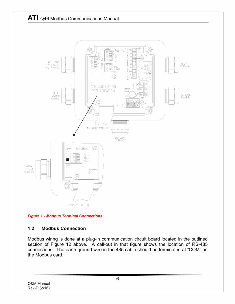
Figure 1 - Modbus Terminal Connections
1.2 Modbus Connection Modbus wiring is done at a plug-in communication circuit board located in the outlined section of Figure 12 above. A call-out in that figure shows the location of RS-485 connections. The earth ground wire in the 485 cable should be terminated at “COM” on the Modbus card.
ATI Q46 Modbus Communications Manual
7
O&M Manual Rev-D (2/16)
1.3 Registers and Coils
Modbus protocol was originally designed to transfer data to and from PLCs (Programmable Logic Controllers), which organize data into groups of registers and coils. PLC registers containing i/o information are called input registers and are numbered 30001 to 39999, while registers containing data or the results of calculations are known as holding registers and are numbered from 40001 to 49999. The term coils, on the other hand, refers to discrete (0 or 1) inputs and outputs. Traditionally, these are inputs from such things as switch closures and outputs to the coils of relays, which are under the control of the PLC. All registers are 16 bit values, which may be read or written to individually, or in blocks by using specific functions. Likewise for coils, which are one bit values. Since register functions transfer 16 bits and discrete (coil) functions transfer only one, it is usually more efficient to use register functions, which reduces the number of messages required to transfer data. For this reason, the Q46 Series transmitter organizes all of its data into input registers only, or more specifically, data is organized into the holding registers starting at 30001. The protocol specifies which registers to access by the value of the function code embedded into the message. For example, to read one or more holding registers in a slave device, the master must use function 3 – “Read Holding Register”. Similarly, the master must use function 4 – “Read Input Register” to read one or more of the input registers. The Q46 only responds to request for reading input registers (Function 4).
For more information on the protocol, please refer to the “Modicon Modbus Protocol Reference Guide” at http://www.modicon.com/techpubs/toc7.html or, “Modbus Protocol Specification”, available for download at http://www.modbus-ida.org/specs.php. Deviations from this guide are noted in the appropriate section. More information regarding Modbus, in general, may be viewed at: http://www.modbus-ida.org/
ATI Q46 Modbus Communications Manual
8
O&M Manual Rev-D (2/16)
1.4 RS-485 Communication
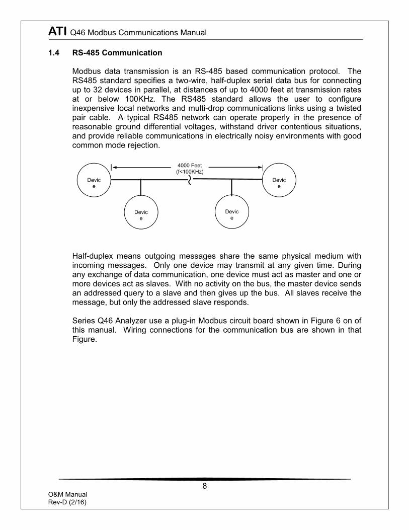
Modbus data transmission is an RS-485 based communication protocol. The RS485 standard specifies a two-wire, half-duplex serial data bus for connecting up to 32 devices in parallel, at distances of up to 4000 feet at transmission rates at or below 100KHz. The RS485 standard allows the user to configure inexpensive local networks and multi-drop communications links using a twisted pair cable. A typical RS485 network can operate properly in the presence of reasonable ground differential voltages, withstand driver contentious situations, and provide reliable communications in electrically noisy environments with good common mode rejection.
Half-duplex means outgoing messages share the same physical medium with incoming messages. Only one device may transmit at any given time. During any exchange of data communication, one device must act as master and one or more devices act as slaves. With no activity on the bus, the master device sends an addressed query to a slave and then gives up the bus. All slaves receive the message, but only the addressed slave responds. Series Q46 Analyzer use a plug-in Modbus circuit board shown in Figure 6 on of this manual. Wiring connections for the communication bus are shown in that Figure.
Devic
e
Devic
e
Devic
e
4000 Feet (f<100KHz)
Device
ATI Q46 Modbus Communications Manual
9
O&M Manual Rev-D (2/16)
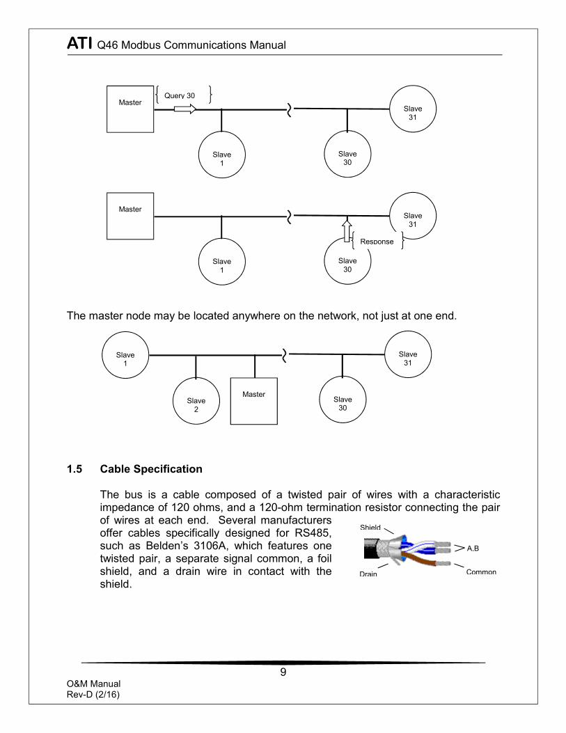
The master node may be located anywhere on the network, not just at one end. 1.5 Cable Specification
The bus is a cable composed of a twisted pair of wires with a characteristic impedance of 120 ohms, and a 120-ohm termination resistor connecting the pair of wires at each end. Several manufacturers offer cables specifically designed for RS485, such as Belden’s 3106A, which features one twisted pair, a separate signal common, a foil shield, and a drain wire in contact with the shield.
Drain
A,B
Common
Shield
Slave
1
Slave
30
Slave
31
Master
Query 30
Slave
1
Slave
30
Slave
31
Master
Response
Slave
1
Slave
30
Slave
31
Master
Slave 2
ATI Q46 Modbus Communications Manual
10
O&M Manual Rev-D (2/16)
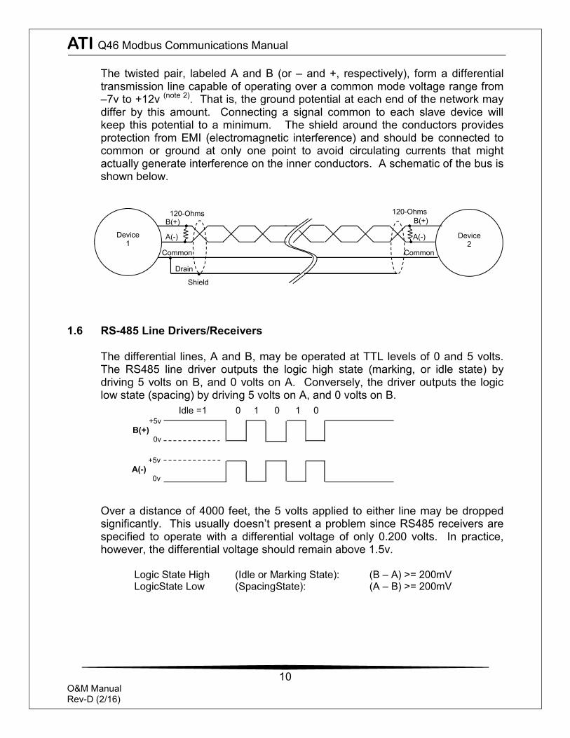
The twisted pair, labeled A and B (or – and +, respectively), form a differential transmission line capable of operating over a common mode voltage range from –7v to +12v (note 2). That is, the ground potential at each end of the network may differ by this amount. Connecting a signal common to each slave device will keep this potential to a minimum. The shield around the conductors provides protection from EMI (electromagnetic interference) and should be connected to common or ground at only one point to avoid circulating currents that might actually generate interference on the inner conductors. A schematic of the bus is shown below.
1.6 RS-485 Line Drivers/Receivers
The differential lines, A and B, may be operated at TTL levels of 0 and 5 volts. The RS485 line driver outputs the logic high state (marking, or idle state) by driving 5 volts on B, and 0 volts on A. Conversely, the driver outputs the logic low state (spacing) by driving 5 volts on A, and 0 volts on B.
Over a distance of 4000 feet, the 5 volts applied to either line may be dropped significantly. This usually doesn’t present a problem since RS485 receivers are specified to operate with a differential voltage of only 0.200 volts. In practice, however, the differential voltage should remain above 1.5v.
Logic State High (Idle or Marking State): (B – A) >= 200mV LogicState Low (SpacingState): (A – B) >= 200mV
Device
1
Device
2 A(-)
B(+)
Common
Shield
Drain
B(+)
A(-)
Common
120-Ohms 120-Ohms
+5v A(-)
0v
+5v B(+)
0v
Idle =1 0 1 0 1 0
ATI Q46 Modbus Communications Manual
11
O&M Manual Rev-D (2/16)
1.7 120 Ohm Termination
The two devices at the furthest end of the bus require termination resistors to cancel reflections. Intermediate devices do not. The Q46 has a selectable termination resistor on the Modbus card just behind the terminal strip. ONLY set to “ON” position if the Q46 is an End-of-Bus unit.
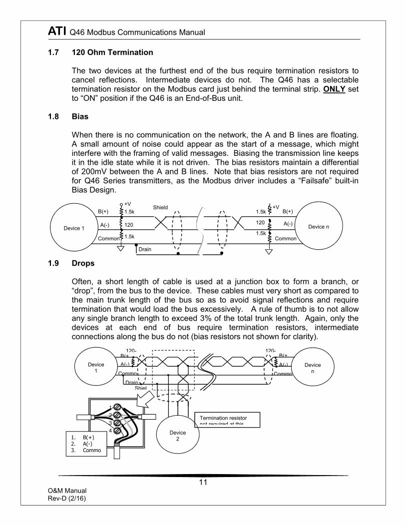
1.8 Bias
When there is no communication on the network, the A and B lines are floating. A small amount of noise could appear as the start of a message, which might interfere with the framing of valid messages. Biasing the transmission line keeps it in the idle state while it is not driven. The bias resistors maintain a differential of 200mV between the A and B lines. Note that bias resistors are not required for Q46 Series transmitters, as the Modbus driver includes a “Failsafe” built-in Bias Design.
1.9 Drops
Often, a short length of cable is used at a junction box to form a branch, or “drop”, from the bus to the device. These cables must very short as compared to the main trunk length of the bus so as to avoid signal reflections and require termination that would load the bus excessively. A rule of thumb is to not allow any single branch length to exceed 3% of the total trunk length. Again, only the devices at each end of bus require termination resistors, intermediate connections along the bus do not (bias resistors not shown for clarity).
1
34
Device
1
Device
n A(-) B(+
Commo
ShielDrain
B(+
A(-)
Commo
Device
2
120- 120-
Termination resistor not required at this
2
1. B(+) 2. A(-) 3. Commo
n
Device 1
A(-)
B(+)
Common
Shield
Drain
B(+)
A(-)
Common
120
+V
120
Device n
+V 1.5k
1.5k
1.5k
1.5k
ATI Q46 Modbus Communications Manual
12
O&M Manual Rev-D (2/16)
Long branches requiring termination may be connected, however, a repeater must be used at a short distance from the connection. Star topologies should be avoided, since terminating each spoke will load the network excessively and reliable communications cannot be guaranteed.
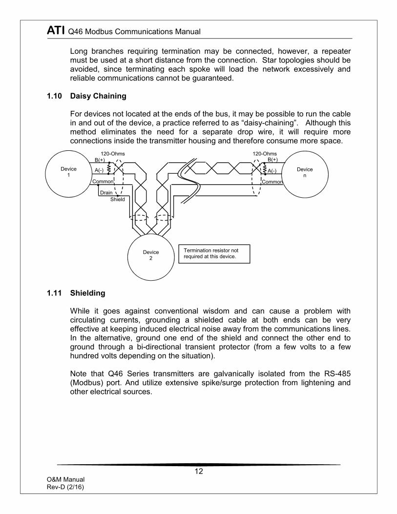
1.10 Daisy Chaining
For devices not located at the ends of the bus, it may be possible to run the cable in and out of the device, a practice referred to as “daisy-chaining”. Although this method eliminates the need for a separate drop wire, it will require more connections inside the transmitter housing and therefore consume more space.
1.11 Shielding
While it goes against conventional wisdom and can cause a problem with circulating currents, grounding a shielded cable at both ends can be very effective at keeping induced electrical noise away from the communications lines. In the alternative, ground one end of the shield and connect the other end to ground through a bi-directional transient protector (from a few volts to a few hundred volts depending on the situation). Note that Q46 Series transmitters are galvanically isolated from the RS-485 (Modbus) port. And utilize extensive spike/surge protection from lightening and other electrical sources.
Device
1
Device
n A(-)
B(+)
Common
Shield Drain
B(+)
A(-)
Common
Device
2
120-Ohms 120-Ohms
Termination resistor not required at this device.
ATI Q46 Modbus Communications Manual
13
O&M Manual Rev-D (2/16)
1.12 Slave Connection Detail
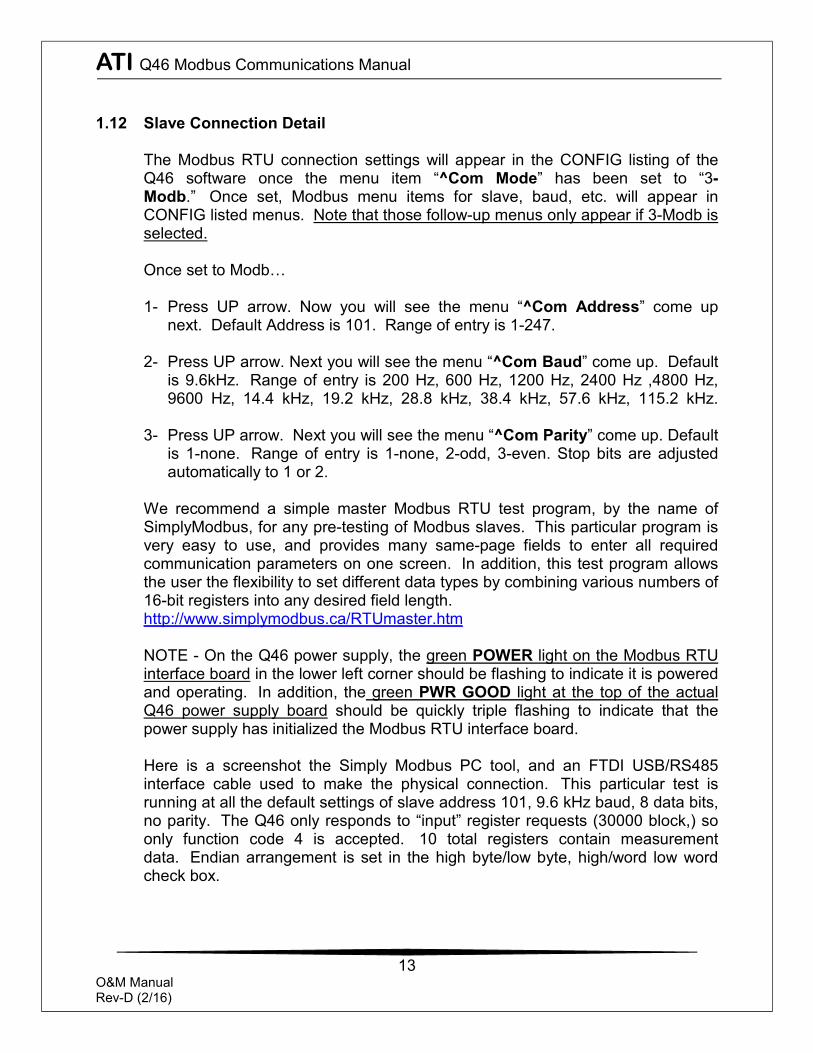
The Modbus RTU connection settings will appear in the CONFIG listing of the Q46 software once the menu item “^Com Mode” has been set to “3-Modb.” Once set, Modbus menu items for slave, baud, etc. will appear in CONFIG listed menus. Note that those follow-up menus only appear if 3-Modb is selected.
Once set to Modb…
1- Press UP arrow. Now you will see the menu “^Com Address” come up
next. Default Address is 101. Range of entry is 1-247. 2- Press UP arrow. Next you will see the menu “^Com Baud” come up. Default
is 9.6kHz. Range of entry is 200 Hz, 600 Hz, 1200 Hz, 2400 Hz ,4800 Hz, 9600 Hz, 14.4 kHz, 19.2 kHz, 28.8 kHz, 38.4 kHz, 57.6 kHz, 115.2 kHz.
3- Press UP arrow. Next you will see the menu “^Com Parity” come up. Default is 1-none. Range of entry is 1-none, 2-odd, 3-even. Stop bits are adjusted automatically to 1 or 2.
We recommend a simple master Modbus RTU test program, by the name of SimplyModbus, for any pre-testing of Modbus slaves. This particular program is very easy to use, and provides many same-page fields to enter all required communication parameters on one screen. In addition, this test program allows the user the flexibility to set different data types by combining various numbers of 16-bit registers into any desired field length. http://www.simplymodbus.ca/RTUmaster.htm
NOTE - On the Q46 power supply, the green POWER light on the Modbus RTU interface board in the lower left corner should be flashing to indicate it is powered and operating. In addition, the green PWR GOOD light at the top of the actual Q46 power supply board should be quickly triple flashing to indicate that the power supply has initialized the Modbus RTU interface board.
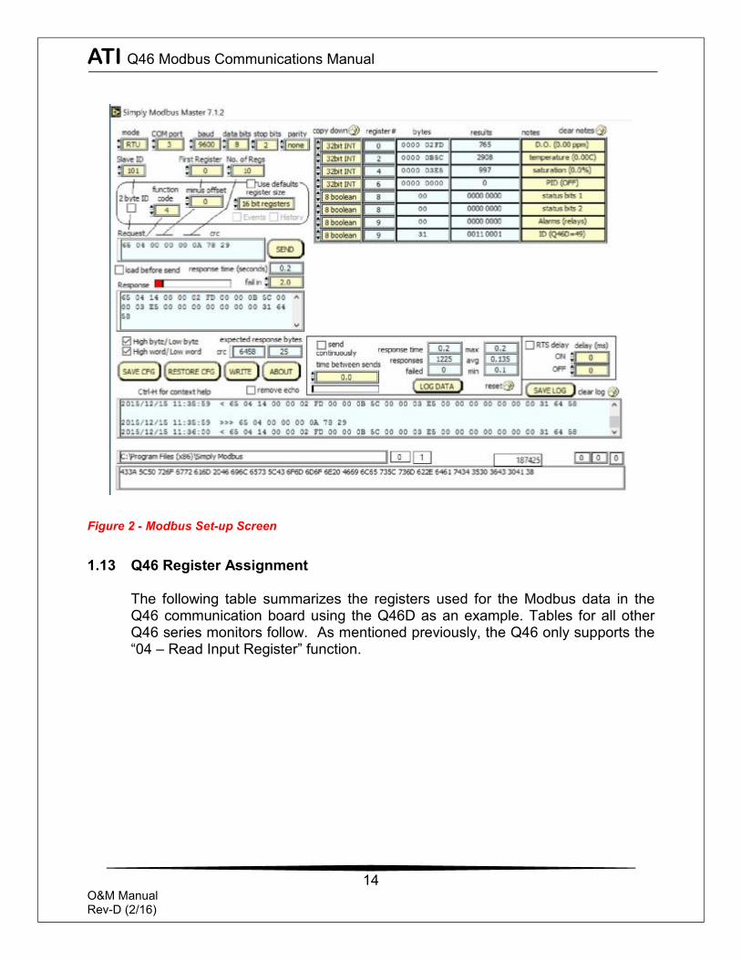
Here is a screenshot the Simply Modbus PC tool, and an FTDI USB/RS485 interface cable used to make the physical connection. This particular test is running at all the default settings of slave address 101, 9.6 kHz baud, 8 data bits, no parity. The Q46 only responds to “input” register requests (30000 block,) so only function code 4 is accepted. 10 total registers contain measurement data. Endian arrangement is set in the high byte/low byte, high/word low word check box.
ATI Q46 Modbus Communications Manual
14
O&M Manual Rev-D (2/16)
Figure 2 - Modbus Set-up Screen
1.13 Q46 Register Assignment
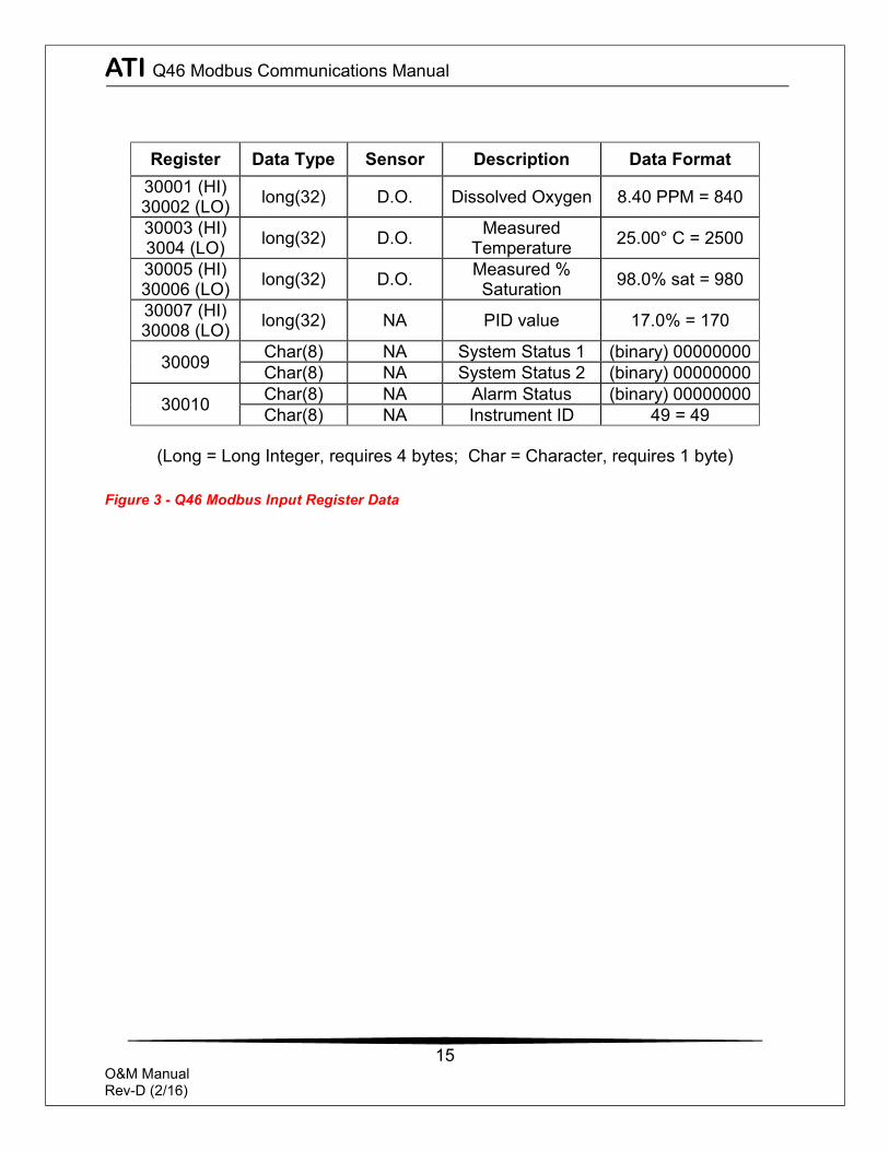
The following table summarizes the registers used for the Modbus data in the Q46 communication board using the Q46D as an example. Tables for all other Q46 series monitors follow. As mentioned previously, the Q46 only supports the “04 – Read Input Register” function.
ATI Q46 Modbus Communications Manual
15
O&M Manual Rev-D (2/16)
(Long = Long Integer, requires 4 bytes; Char = Character, requires 1 byte)
Figure 3 - Q46 Modbus Input Register Data
Register Data Type Sensor Description Data Format 30001 (HI) 30002 (LO) long(32) D.O. Dissolved Oxygen 8.40 PPM = 840
30003 (HI) 3004 (LO) long(32) D.O. Measured
Temperature 25.00° C = 2500
30005 (HI) 30006 (LO) long(32) D.O. Measured %
Saturation 98.0% sat = 980
30007 (HI) 30008 (LO) long(32) NA PID value 17.0% = 170
30009 Char(8) NA System Status 1 (binary) 00000000 Char(8) NA System Status 2 (binary) 00000000
30010 Char(8) NA Alarm Status (binary) 00000000 Char(8) NA Instrument ID 49 = 49
ATI Q46 Modbus Communications Manual
16
O&M Manual Rev-D (2/16)
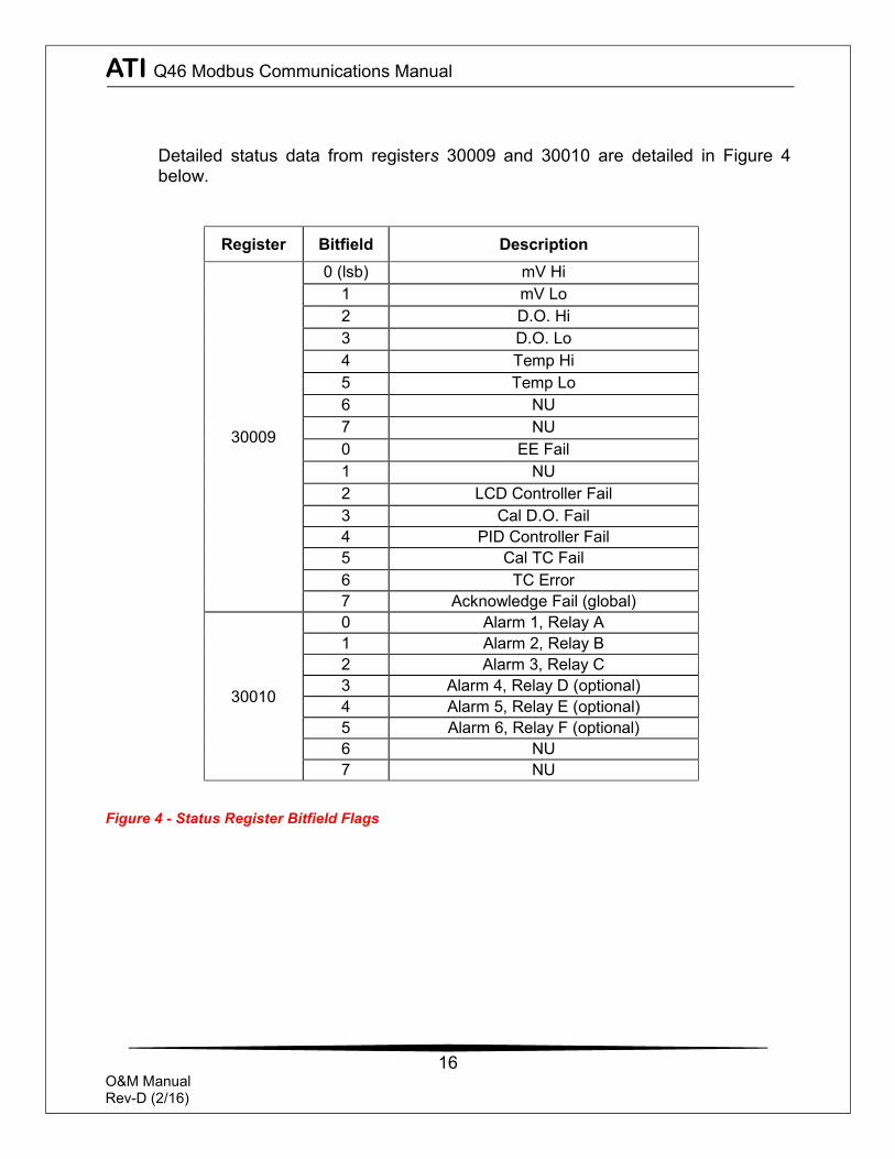
Detailed status data from registers 30009 and 30010 are detailed in Figure 4 below.
Register Bitfield Description
30009
0 (lsb) mV Hi 1 mV Lo 2 D.O. Hi 3 D.O. Lo 4 Temp Hi 5 Temp Lo 6 NU 7 NU 0 EE Fail 1 NU 2 LCD Controller Fail 3 Cal D.O. Fail 4 PID Controller Fail 5 Cal TC Fail 6 TC Error 7 Acknowledge Fail (global)
30010
0 Alarm 1, Relay A 1 Alarm 2, Relay B 2 Alarm 3, Relay C 3 Alarm 4, Relay D (optional) 4 Alarm 5, Relay E (optional) 5 Alarm 6, Relay F (optional) 6 NU 7 NU
Figure 4 - Status Register Bitfield Flags
ATI Q46 Modbus Communications Manual
17
O&M Manual Rev-D (2/16)
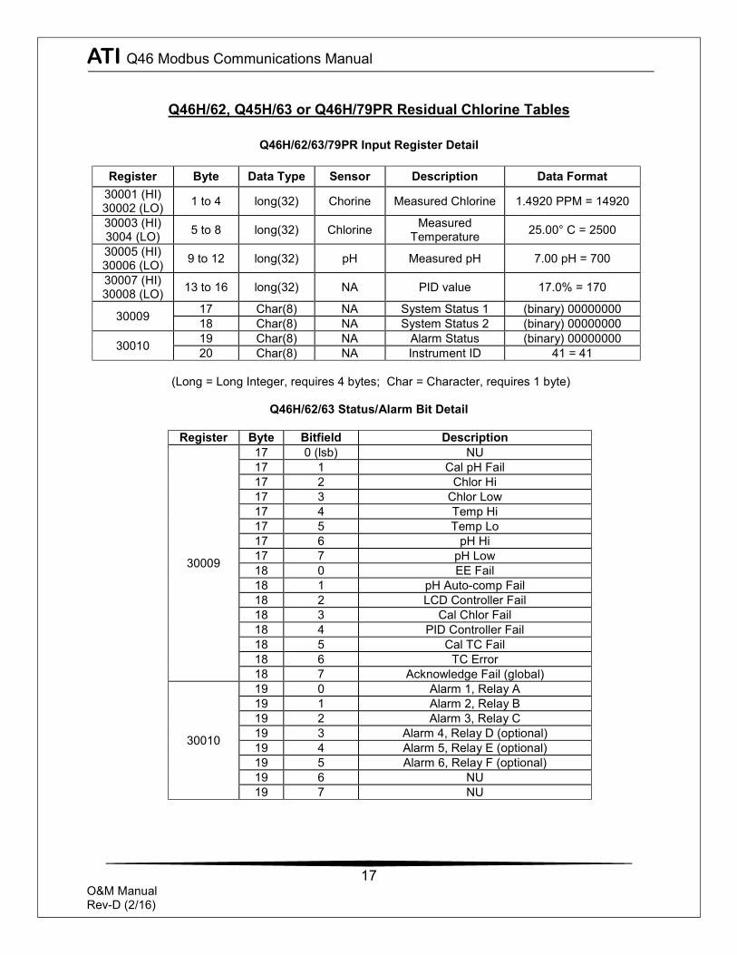
Q46H/62, Q45H/63 or Q46H/79PR Residual Chlorine Tables
Q46H/62/63/79PR Input Register Detail
Register Byte Data Type Sensor Description Data Format 30001 (HI) 30002 (LO) 1 to 4 long(32) Chorine Measured Chlorine 1.4920 PPM = 14920
30003 (HI) 3004 (LO) 5 to 8 long(32) Chlorine Measured
Temperature 25.00° C = 2500
30005 (HI) 30006 (LO) 9 to 12 long(32) pH Measured pH 7.00 pH = 700
30007 (HI) 30008 (LO) 13 to 16 long(32) NA PID value 17.0% = 170
30009 17 Char(8) NA System Status 1 (binary) 00000000 18 Char(8) NA System Status 2 (binary) 00000000
30010 19 Char(8) NA Alarm Status (binary) 00000000 20 Char(8) NA Instrument ID 41 = 41
(Long = Long Integer, requires 4 bytes; Char = Character, requires 1 byte)
Q46H/62/63 Status/Alarm Bit Detail
Register Byte Bitfield Description
30009
17 0 (lsb) NU 17 1 Cal pH Fail 17 2 Chlor Hi 17 3 Chlor Low 17 4 Temp Hi 17 5 Temp Lo 17 6 pH Hi 17 7 pH Low 18 0 EE Fail 18 1 pH Auto-comp Fail 18 2 LCD Controller Fail 18 3 Cal Chlor Fail 18 4 PID Controller Fail 18 5 Cal TC Fail 18 6 TC Error 18 7 Acknowledge Fail (global)
30010
19 0 Alarm 1, Relay A 19 1 Alarm 2, Relay B 19 2 Alarm 3, Relay C 19 3 Alarm 4, Relay D (optional) 19 4 Alarm 5, Relay E (optional) 19 5 Alarm 6, Relay F (optional) 19 6 NU 19 7 NU
ATI Q46 Modbus Communications Manual
18
O&M Manual Rev-D (2/16)
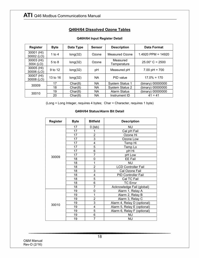
Q46H/64 Dissolved Ozone Tables
Q46H/64 Input Register Detail
Register Byte Data Type Sensor Description Data Format 30001 (HI) 30002 (LO) 1 to 4 long(32) Ozone Measured Ozone 1.4920 PPM = 14920
30003 (HI) 3004 (LO) 5 to 8 long(32) Ozone Measured
Temperature 25.00° C = 2500
30005 (HI) 30006 (LO) 9 to 12 long(32) pH Measured pH 7.00 pH = 700
30007 (HI) 30008 (LO) 13 to 16 long(32) NA PID value 17.0% = 170
30009 17 Char(8) NA System Status 1 (binary) 00000000 18 Char(8) NA System Status 2 (binary) 00000000
30010 19 Char(8) NA Alarm Status (binary) 00000000 20 Char(8) NA Instrument ID 41 = 41
(Long = Long Integer, requires 4 bytes; Char = Character, requires 1 byte)
Q46H/64 Status/Alarm Bit Detail
Register Byte Bitfield Description
30009
17 0 (lsb) NU 17 1 Cal pH Fail 17 2 Ozone Hi 17 3 Ozone Low 17 4 Temp Hi 17 5 Temp Lo 17 6 pH Hi 17 7 pH Low 18 0 EE Fail 18 1 NU 18 2 LCD Controller Fail 18 3 Cal Ozone Fail 18 4 PID Controller Fail 18 5 Cal TC Fail 18 6 TC Error 18 7 Acknowledge Fail (global)
30010
19 0 Alarm 1, Relay A 19 1 Alarm 2, Relay B 19 2 Alarm 3, Relay C 19 3 Alarm 4, Relay D (optional) 19 4 Alarm 5, Relay E (optional) 19 5 Alarm 6, Relay F (optional) 19 6 NU 19 7 NU
ATI Q46 Modbus Communications Manual
19
O&M Manual Rev-D (2/16)
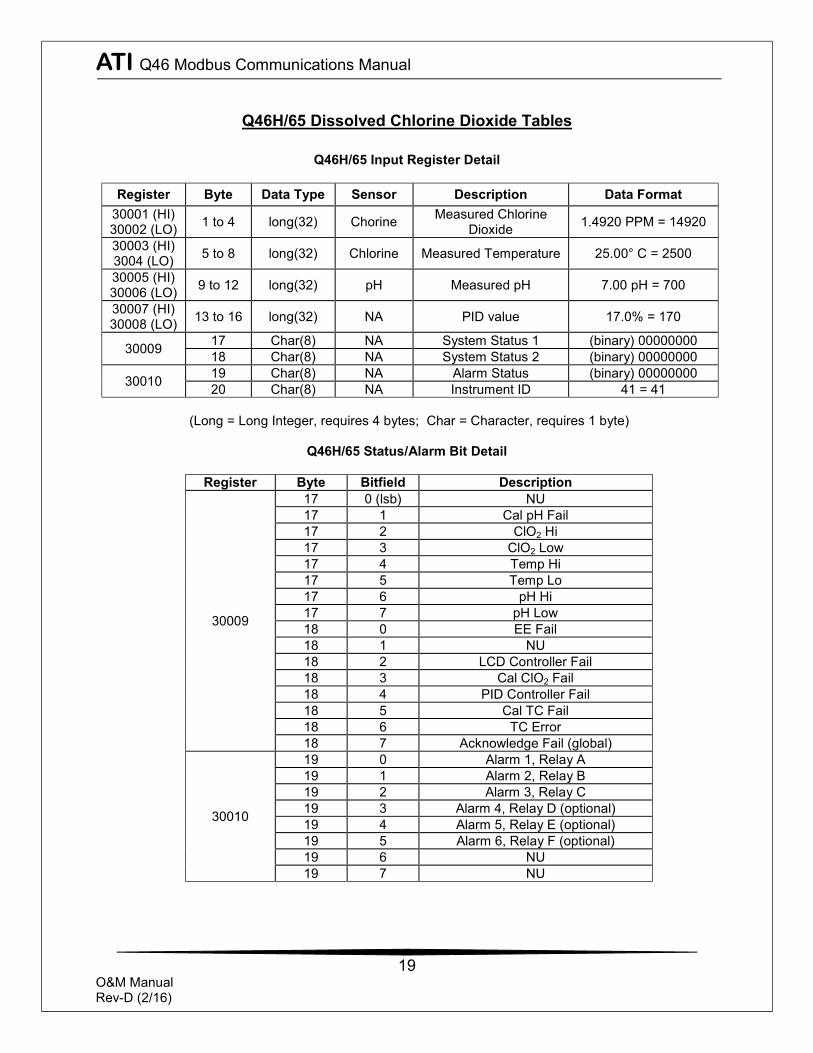
Q46H/65 Dissolved Chlorine Dioxide Tables
Q46H/65 Input Register Detail
Register Byte Data Type Sensor Description Data Format 30001 (HI) 30002 (LO) 1 to 4 long(32) Chorine Measured Chlorine
Dioxide 1.4920 PPM = 14920
30003 (HI) 3004 (LO) 5 to 8 long(32) Chlorine Measured Temperature 25.00° C = 2500
30005 (HI) 30006 (LO) 9 to 12 long(32) pH Measured pH 7.00 pH = 700
30007 (HI) 30008 (LO) 13 to 16 long(32) NA PID value 17.0% = 170
30009 17 Char(8) NA System Status 1 (binary) 00000000 18 Char(8) NA System Status 2 (binary) 00000000
30010 19 Char(8) NA Alarm Status (binary) 00000000 20 Char(8) NA Instrument ID 41 = 41
(Long = Long Integer, requires 4 bytes; Char = Character, requires 1 byte)
Q46H/65 Status/Alarm Bit Detail
Register Byte Bitfield Description
30009
17 0 (lsb) NU 17 1 Cal pH Fail 17 2 ClO2 Hi 17 3 ClO2 Low 17 4 Temp Hi 17 5 Temp Lo 17 6 pH Hi 17 7 pH Low 18 0 EE Fail 18 1 NU 18 2 LCD Controller Fail 18 3 Cal ClO2 Fail 18 4 PID Controller Fail 18 5 Cal TC Fail 18 6 TC Error 18 7 Acknowledge Fail (global)
30010
19 0 Alarm 1, Relay A 19 1 Alarm 2, Relay B 19 2 Alarm 3, Relay C 19 3 Alarm 4, Relay D (optional) 19 4 Alarm 5, Relay E (optional) 19 5 Alarm 6, Relay F (optional) 19 6 NU 19 7 NU
ATI Q46 Modbus Communications Manual
20
O&M Manual Rev-D (2/16)
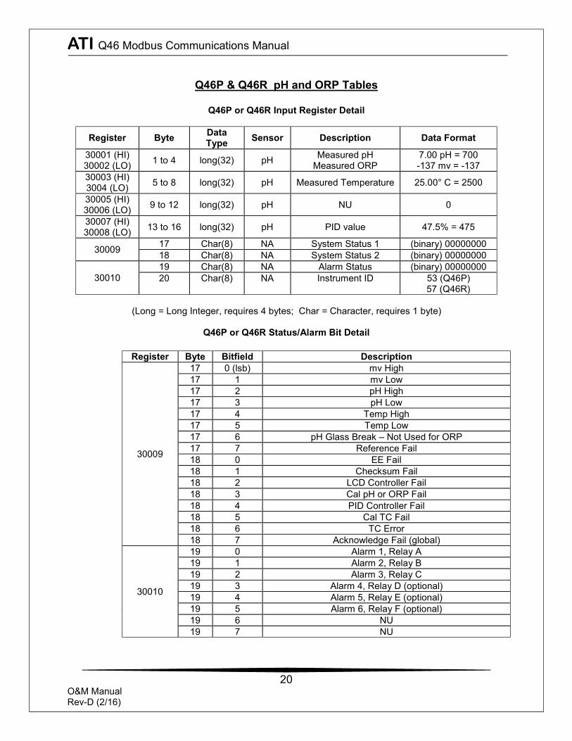
Q46P & Q46R pH and ORP Tables
Q46P or Q46R Input Register Detail
Register Byte Data Type Sensor Description Data Format
30001 (HI) 30002 (LO) 1 to 4 long(32) pH Measured pH
Measured ORP 7.00 pH = 700 -137 mv = -137
30003 (HI) 3004 (LO) 5 to 8 long(32) pH Measured Temperature 25.00° C = 2500
30005 (HI) 30006 (LO) 9 to 12 long(32) pH NU 0
30007 (HI) 30008 (LO) 13 to 16 long(32) pH PID value 47.5% = 475
30009 17 Char(8) NA System Status 1 (binary) 00000000 18 Char(8) NA System Status 2 (binary) 00000000
30010 19 Char(8) NA Alarm Status (binary) 00000000 20 Char(8) NA Instrument ID 53 (Q46P)
57 (Q46R)
(Long = Long Integer, requires 4 bytes; Char = Character, requires 1 byte)
Q46P or Q46R Status/Alarm Bit Detail
Register Byte Bitfield Description
30009
17 0 (lsb) mv High 17 1 mv Low 17 2 pH High 17 3 pH Low 17 4 Temp High 17 5 Temp Low 17 6 pH Glass Break – Not Used for ORP 17 7 Reference Fail 18 0 EE Fail 18 1 Checksum Fail 18 2 LCD Controller Fail 18 3 Cal pH or ORP Fail 18 4 PID Controller Fail 18 5 Cal TC Fail 18 6 TC Error 18 7 Acknowledge Fail (global)
30010
19 0 Alarm 1, Relay A 19 1 Alarm 2, Relay B 19 2 Alarm 3, Relay C 19 3 Alarm 4, Relay D (optional) 19 4 Alarm 5, Relay E (optional) 19 5 Alarm 6, Relay F (optional) 19 6 NU 19 7 NU

ATI Q46 Modbus Communications Manual
21
O&M Manual Rev-D (2/16)
Q46N Total and Free Ammonia Tables
Q46N & Q46FN Input Register Detail
Register Byte Data Type Sensor Description Data Format
30001 (HI) 30002 (LO) 1 to 4 long(32) Ammonia Measured Total
Ammonia 1.00 PPM = 100
30003 (HI) 3004 (LO) 5 to 8 long(32) Ammonia Measured Temperature 25.00°C = 2500
30005 (HI) 30006 (LO) 9 to 12 long(32) Monochlor Measured
Monochloramine 0.51 PPM = 51
30007 (HI) 30008 (LO) 13 to 16 long(32) Amm/Mono Measured Free
Ammonia 3.21 PPM = 321
30009 17 Char(8) NA System Status 1 (binary) 00000000 18 Char(8) NA System Status 2 (binary) 00000000
30010 19 Char(8) NA Alarm Status (binary) 00000000 20 Char(8) NA Instrument ID 45 = 45
(Long = Long Integer, requires 4 bytes; Char = Character, requires 1 byte)
Q46N & Q46FN Status/Alarm Bit Detail
Register Bitfield Description
30009
0 (lsb) NU 1 NU 2 Ammonia Hi 3 Ammonia Low 4 Temp Hi 5 Temp Lo 6 MonoChlor Hi 7 MonoChlor Low 0 Cal Monochlor Fail 1 NU 2 LCD Controller Fail 3 Cal Ammonia Fail 4 PID Controller Fail 5 Cal TC Fail 6 TC Error 7 Acknowledge Fail (global)
30010
0 Alarm 1, Relay A 1 Alarm 2, Relay B 2 Alarm 3, Relay C 3 Alarm 4, Relay D (optional) 4 Alarm 5, Relay E (optional) 5 Alarm 6, Relay F (optional) 6 NU 7 NU
ATI Q46 Modbus Communications Manual
22
O&M Manual Rev-D (2/16)
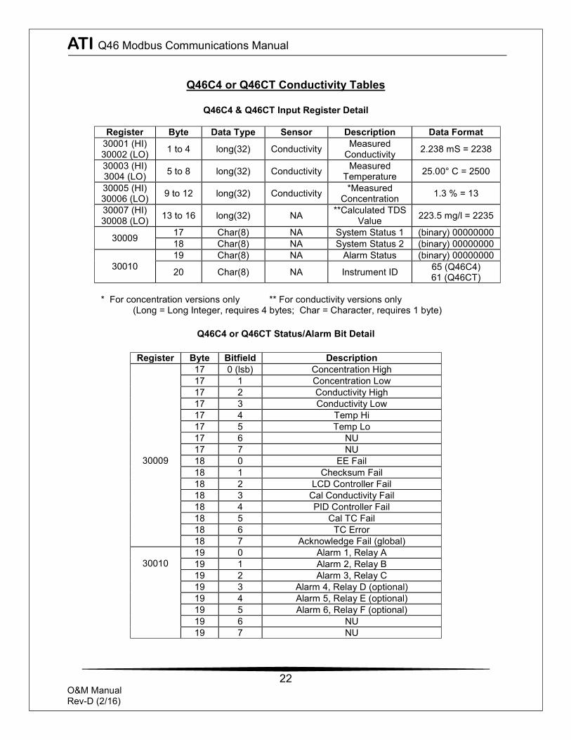
Q46C4 or Q46CT Conductivity Tables
Q46C4 & Q46CT Input Register Detail
Register Byte Data Type Sensor Description Data Format 30001 (HI) 30002 (LO) 1 to 4 long(32) Conductivity Measured
Conductivity 2.238 mS = 2238
30003 (HI) 3004 (LO) 5 to 8 long(32) Conductivity Measured
Temperature 25.00° C = 2500
30005 (HI) 30006 (LO) 9 to 12 long(32) Conductivity *Measured
Concentration 1.3 % = 13
30007 (HI) 30008 (LO) 13 to 16 long(32) NA **Calculated TDS
Value 223.5 mg/l = 2235
30009 17 Char(8) NA System Status 1 (binary) 00000000 18 Char(8) NA System Status 2 (binary) 00000000
30010 19 Char(8) NA Alarm Status (binary) 00000000
20 Char(8) NA Instrument ID 65 (Q46C4) 61 (Q46CT)
* For concentration versions only ** For conductivity versions only
(Long = Long Integer, requires 4 bytes; Char = Character, requires 1 byte)
Q46C4 or Q46CT Status/Alarm Bit Detail
Register Byte Bitfield Description
30009
17 0 (lsb) Concentration High 17 1 Concentration Low 17 2 Conductivity High 17 3 Conductivity Low 17 4 Temp Hi 17 5 Temp Lo 17 6 NU 17 7 NU 18 0 EE Fail 18 1 Checksum Fail 18 2 LCD Controller Fail 18 3 Cal Conductivity Fail 18 4 PID Controller Fail 18 5 Cal TC Fail 18 6 TC Error 18 7 Acknowledge Fail (global)
30010
19 0 Alarm 1, Relay A 19 1 Alarm 2, Relay B 19 2 Alarm 3, Relay C 19 3 Alarm 4, Relay D (optional) 19 4 Alarm 5, Relay E (optional) 19 5 Alarm 6, Relay F (optional) 19 6 NU 19 7 NU
ATI Q46 Modbus Communications Manual
23
O&M Manual Rev-D (2/16)
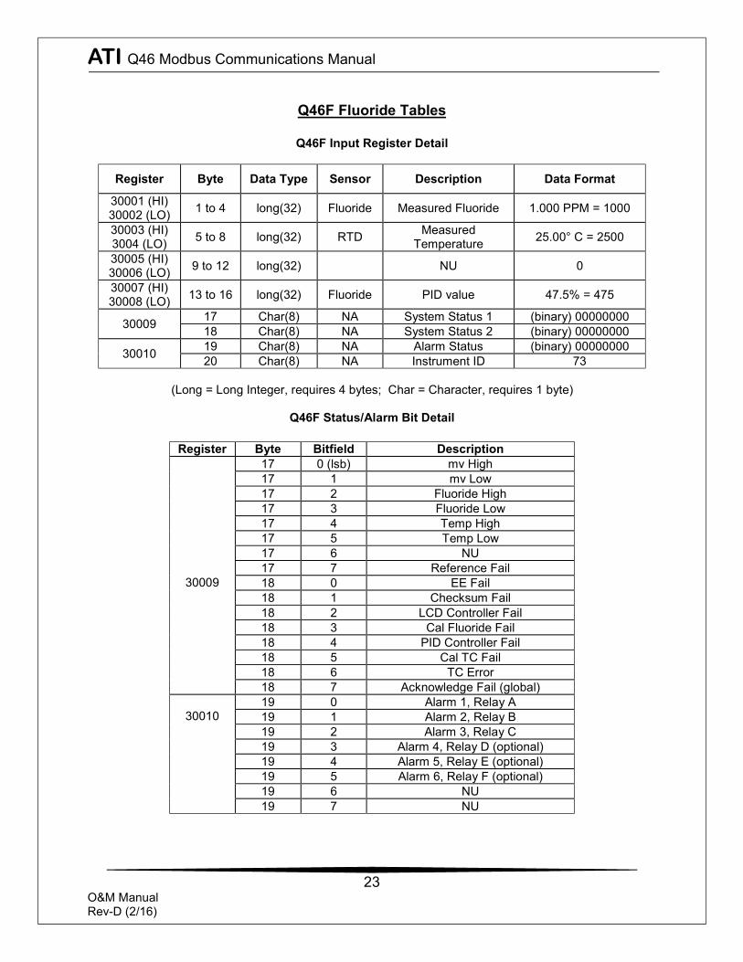
Q46F Fluoride Tables
Q46F Input Register Detail
Register Byte Data Type Sensor Description Data Format
30001 (HI) 30002 (LO) 1 to 4 long(32) Fluoride Measured Fluoride 1.000 PPM = 1000
30003 (HI) 3004 (LO) 5 to 8 long(32) RTD Measured
Temperature 25.00° C = 2500
30005 (HI) 30006 (LO) 9 to 12 long(32) NU 0
30007 (HI) 30008 (LO) 13 to 16 long(32) Fluoride PID value 47.5% = 475
30009 17 Char(8) NA System Status 1 (binary) 00000000 18 Char(8) NA System Status 2 (binary) 00000000
30010 19 Char(8) NA Alarm Status (binary) 00000000 20 Char(8) NA Instrument ID 73
(Long = Long Integer, requires 4 bytes; Char = Character, requires 1 byte)
Q46F Status/Alarm Bit Detail
Register Byte Bitfield Description
30009
17 0 (lsb) mv High 17 1 mv Low 17 2 Fluoride High 17 3 Fluoride Low 17 4 Temp High 17 5 Temp Low 17 6 NU 17 7 Reference Fail 18 0 EE Fail 18 1 Checksum Fail 18 2 LCD Controller Fail 18 3 Cal Fluoride Fail 18 4 PID Controller Fail 18 5 Cal TC Fail 18 6 TC Error 18 7 Acknowledge Fail (global)
30010
19 0 Alarm 1, Relay A 19 1 Alarm 2, Relay B 19 2 Alarm 3, Relay C 19 3 Alarm 4, Relay D (optional) 19 4 Alarm 5, Relay E (optional) 19 5 Alarm 6, Relay F (optional) 19 6 NU 19 7 NU
ATI Q46 Modbus Communications Manual
24
O&M Manual Rev-D (2/16)
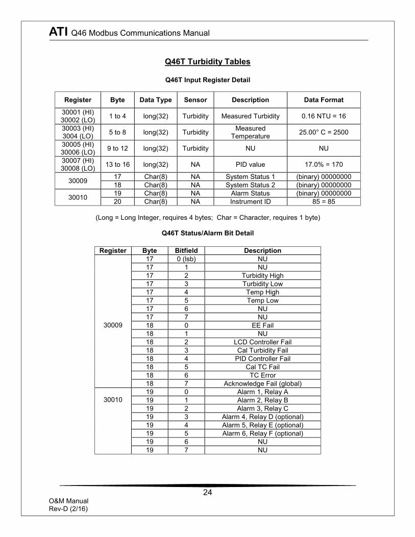
Q46T Turbidity Tables
Q46T Input Register Detail
Register Byte Data Type Sensor Description Data Format
30001 (HI) 30002 (LO) 1 to 4 long(32) Turbidity Measured Turbidity 0.16 NTU = 16
30003 (HI) 3004 (LO) 5 to 8 long(32) Turbidity Measured
Temperature 25.00° C = 2500
30005 (HI) 30006 (LO) 9 to 12 long(32) Turbidity NU NU
30007 (HI) 30008 (LO) 13 to 16 long(32) NA PID value 17.0% = 170
30009 17 Char(8) NA System Status 1 (binary) 00000000 18 Char(8) NA System Status 2 (binary) 00000000
30010 19 Char(8) NA Alarm Status (binary) 00000000 20 Char(8) NA Instrument ID 85 = 85
(Long = Long Integer, requires 4 bytes; Char = Character, requires 1 byte)
Q46T Status/Alarm Bit Detail
Register Byte Bitfield Description
30009
17 0 (lsb) NU 17 1 NU 17 2 Turbidity High 17 3 Turbidity Low 17 4 Temp High 17 5 Temp Low 17 6 NU 17 7 NU 18 0 EE Fail 18 1 NU 18 2 LCD Controller Fail 18 3 Cal Turbidity Fail 18 4 PID Controller Fail 18 5 Cal TC Fail 18 6 TC Error 18 7 Acknowledge Fail (global)
30010
19 0 Alarm 1, Relay A 19 1 Alarm 2, Relay B 19 2 Alarm 3, Relay C 19 3 Alarm 4, Relay D (optional) 19 4 Alarm 5, Relay E (optional) 19 5 Alarm 6, Relay F (optional) 19 6 NU 19 7 NU