Embed Size (px)
Citation preview

MODEL : PP 180 SP
GENERATING SET PERFORMANCE 50Hz 60Hz
VOLTAGE V400
PHASES Three
PRIME RATED POWER 180kVA
STANDBY RATED POWER 200kVA
POWER FACTOR 0.80 PF
FUEL USAGE @ 75% 31.0 L/hr
Powered by:

ENGINE PERKINS 1106C-E66TAG4
PERFORMANCE 50Hz 60Hz
BASELOAD RATED POWER TBA
PRIME RATED POWER 175KWm
STANDBY RATED POWER 158KWm
FUEL CONSUMPTION 206g/KWh @ 100% 212g/KWh @ 75% 211g/KWh @ 50%
TYPE Diesel 4 stroke
ASPIRATION
INJECTION TYPE Direct injection
ENGINE GOVERNOR Electronic governor
CYLINDERS AND ARRANGEMENT Six in line
BORE AND STROKE 105mm x 127mm
COMPRESSION RATIO 16.2 : 1
ELECTRICAL SYSTEM VOLTAGE 12 volt
BATTERY TYPE Lead acid, 12V
DERATING FOR TEMPERATURE 40 deg C
DERATING FOR ALTITUDE 1000m
DERATING FOR HUMIDITY 90%
Turbocharged air to air charge cooled
Murphy EL150K water level sensor to constantly monitor the radiator water level. It will put the generator into shut down in event of loss of coolant regardless of if the unit is running or not.
Powered by a world renowned Perkins Engine backed by a world wide OEM warranty.
Water jacket heater to keep the engine at optimum temperature whilst in standby. Configured to sense water temperature whilst stationary and provide an alarm in event of a failure of the heater.
ENGINE

ALTERNATOR STAMFORD
PERFORMANCE 50Hz 60Hz
MODEL UCI274H
BASELOAD RATED POWER 40 deg C 182kVA
PRIME RATED POWER 40 deg C 200kVA
STANDBY RATED POWER 40 deg C 212kVA
STANDBY RATED POWER 27 deg C 220kVA
EFFICIENCY 93%
STANDARD WING CONNECTIONS Star Delta
EXCITER
POLES 4 poles
PHASES Three phases
WIRES 12 leads
VOLTAGE REGULATION +/- 1.0%
INSULATION CLASS Class H
ENCLOSURE IP23
MAXIMUM OVERSPEED 150%
STANDARD AVR MODEL MX341
OPTIONAL AVR MODEL MX321
DERATING FOR TEMPERATURE 40 deg C
DERATING FOR ALTITUDE 1000mm
Separately excited by P.M.G.
Electrical power is generated using the well recognised Stamford Newage alternator.
Anti condensation heater to keep the alternator windings at optimum temperature whilst the generator is in standby.
Permanent Magnet Generator separate excitation system to offer optimum load response and durability to unbalanced or highly harmonic load types.
ALTERNATOR
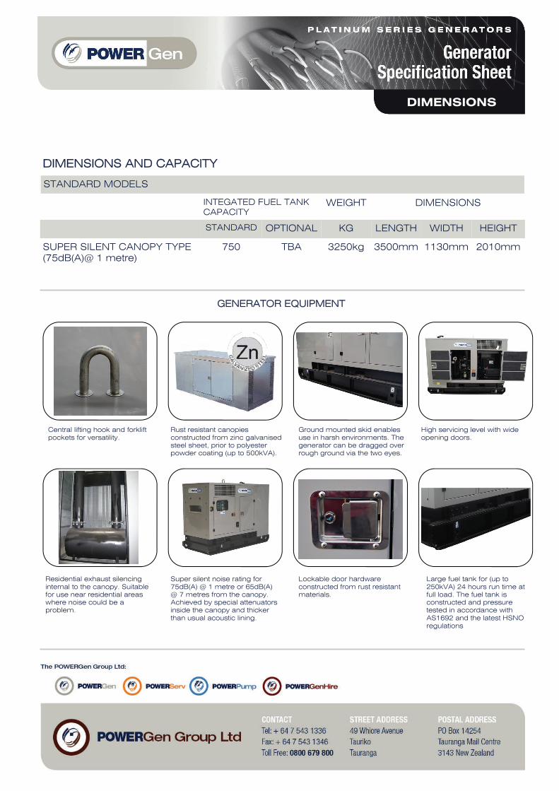
GENERATOR EQUIPMENT
DIMENSIONS AND CAPACITY
STANDARD MODELS
INTEGATED FUEL TANK CAPACITY
WEIGHT
STANDARD OPTIONAL KG LENGTH WIDTH HEIGHT
SUPER SILENT CANOPY TYPE (75dB(A)@ 1 metre)
750 TBA 3250kg 3500mm 1130mm 2010mm
DIMENSIONS
Central lifting hook and forklift pockets for versatility.
Rust resistant canopies constructed from zinc galvanised steel sheet, prior to polyester powder coating (up to 500kVA).
Ground mounted skid enables use in harsh environments. The generator can be dragged over rough ground via the two eyes.
High servicing level with wide opening doors.
Residential exhaust silencing internal to the canopy. Suitable for use near residential areas where noise could be a problem.
Super silent noise rating for 75dB(A) @ 1 metre or 65dB(A) @ 7 metres from the canopy. Achieved by special attenuators inside the canopy and thicker than usual acoustic lining.
Lockable door hardware constructed from rust resistant materials.
Large fuel tank for (up to 250kVA) 24 hours run time at full load. The fuel tank is constructed and pressure tested in accordance with AS1692 and the latest HSNO regulations
DIMENSIONS

AUTOMATIC MODELS – EQUIPMENT
4 poles ABB circuit breaker, electronic control unit ComAp AMF25-NT control panel box key, emergency stop button, water jacket heater, battery charger, anti condensation heater.
AUTOMATIC MODELS – PROTECTORS
Low oil pressure, low fuel level, overload, over/ under frequency, low voltage, over/ under battery voltage, belt breakage.
AUTOMATIC MODELS – INSTRUMENTATION
Voltmeter, ammeter (3 phases), frequency meter, hour meter, battery voltage, fuel level.
Dedicated battery charger with boost and flat modes. Battery charger is configured to provide an alarm in event of a fault with the charging system.
Wiring and protection in accordance with AS3000 and AS3010. Robust, clear labelling system with comprehensive schematic drawings.
Option of a high spec controller capable of synchronising with other generators or the mains supply. Standard controller can be used in key start or standard AMF mode.
Battery isolator to enable the battery to be switched off in the event of the generator being put into storage for extended periods.
Range of standard New Zealand series 56 single phase and three phase sockets on units up to 150kVA. Additional sockets available on request.
CONTROLLER
Four pole MCCB in accordance with AS3010. The motorised MCCB is fitted with a stunt trip to protect the generator in event of a sudden shutdown.

The 1106C-E66TAG ElectropaKs arethe latest addition to Perkins 1100Series Electric Power line-up. Offeringimproved power density from acompact package, these ElectropaK’sbuild on Perkins reputation within thePower Generation Industry.
These ultra clean engines areassembled on a new high technologyproduction line. Frequent computerisedchecks during the production processensure high build quality is maintainedthroughout.
Hitting the key power nodes requiredby the market, the 1106C-E66TAGproduct line-up consists of threemodels offering a power solution forboth Prime and Standby applications,in 50 Hz and 60 Hz territories.
1100 Series1106C-E66TAG4Diesel Engine - ElectropaK
175.5 kWm @ 1500 rev/min196.3 kWm @ 1800 rev/min
Power to Meet your NeedsHitting the key power nodes required by the market, the 1106C-E66TAG4 ElectropaKhas been developed to provide a clean and cost effective power solution.
State of the Art DesignThe 1106C-E66TAG4 incorporates the latest common-rail fuel system technologieswith a closely optimised air-management system which is overseen by the latestgeneration of electronic engine control. This allows the 1106C ElectropaK range todeliver high power density, low exhaust emissions with the minimum of heat rejectionand excellent fuel economy.
Worldwide Power SolutionThe 1106C has been designed to be worldwide fuel tolerant, including kerosene, jetaviation fuel and 5% biofuel (RME). Options are available to meet local market needs.
Product Support� Perkins actively pursues product support excellence by ensuring our distribution
network invest in their territory - strengthening relationships and providing morevalue to you, our customer
� Through an experienced global network of distributors and dealers, fully trainedengine experts deliver total service support around the clock, 365 days a year.They have a comprehensive suite of web based tools at their fingertips coveringtechnical information, parts identification and ordering systems, all dedicated tomaximising the productivity of your engine
� Throughout the entire life of a Perkins engine, we provide access to genuine OEspecification parts and service. We give 100% reassurance that you receive thevery best in terms of quality for lowest possible cost .. wherever your Perkinspowered machine is operating in the world
Long-term Power SolutionThe 1106C-E66TAG ElectropaK range has been designed to fully comply with EUStage II emissions regulations, providing an emissions compliant power solution forthe future.
Certified against the requirements of EU2007 legislation for non-road mobile machinery,powered by constant speed engines (EU97/68/EC Stage II).
Engine speed Type of Typical generator Engine power
(rev/min) Operation output (net) Gross NetkVA kWe kWm bhp kWm bhp
1500 Prime 180.0 144.0 163.3 218.9 158.4 212.4Standby (maximum) 200.0 160.0 180.4 242.0 175.5 235.3
1800 Prime 200.0 160.0 185.3 248.4 177.3 237.7Standby (maximum) 219.0 175.0 204.3 274.0 196.3 263.2
The above ratings represent the engine performance capabilities to conditions specified in ISO 8528/5Derating may be required for conditions outside the test conditions; consult Perkins Engines Company LimitedGenerator powers are typical and are based on typical alternator efficiencies and a power factorFuel specification: Consult Perkins Engines Company Limited (various fuel specifications are available)Lubricating oil: multi-grade oil conforming to API-CH4/CI4 must be usedRating DefinitionsPrime Power: Power available at variable load in lieu of a main power network. Overload of 10% is permitted for 1 hour in every 12 hours’ operationStandby (maximum): Power available at variable load in the event of a main power network failure. No overload is permitted
All information in this document is substantially correct at time of printing and may be altered subsequently Publication No.1863/10/08 Produced in England ©2006 Perkins Engines Company Limited

Perkins Engines Company LimitedPeterborough PE1 5NAUnited KingdomTelephone +44 (0)1733 583000Fax +44 (0)1733 582240www.perkins.com
All information in this document is substantially correct at time of printing and may be altered subsequentlyPublication No.1863/10/08 Produced in England ©2006 Perkins Engines Company Limited
Standard ElectropaK Specification
Air inlet� Mounted air filter and turbocharger
Cooling system� 27” belt-driven pusher fan and guards� Radiator (incorporating air-to-air charge cooler + fuel cooler)� Water pump
Electric system� 12 volt starter motor� 12 volt, 100 amp alternator with DC output
Flywheel and housing� High inertia flywheel� SAE2 flywheel housing
Fuel system� Electronic governing (confirms to Class G3 ISO 8528-5)� Fuel filter
Literature� User’s Handbook
Lubrication system� Flat-bottomed isolated aluminium sump� Oil filter
Start aids� Glow plugs
Distributed by
1100 Series1106C-E66TAG4
General DataNumber of cylinders 6 in-lineBore and stroke 105 mm x 127 mmDisplacement 6.6 litresAspiration Turbocharged air-to-air
charge cooledCycle 4 strokeCombustion system Direct injectionCompression ratio 16.2:1Rotation Anti-clockwise viewed on
flywheelCooling system WaterDimensions Length 1784 mm*
Width 777 mmHeight 1144 mm
Dry weight 714 kgWet weight 757 kg
* Length includes air cleanerFinal weight and dimensions will depend on completed specification
1784 mm 777 mm
1144 mm
1144 mm
Fuel Consumption
Engine Speed1500 rev/min 1800 rev/min
g/kWh l/hr g/kWh l/hr
Standby 204.9 44.0 207.5 50.5
Prime power 206.9 40.2 211.1 41.3
110% of prime 205.1 43.8 208.0 50.4power
75% of prime 212.7 31.0 222.7 36.8power
50% of prime 211.6 20.5 231.6 25.5power


New InteliLiteNT
SINGLE SET GEN-SET CONTROLLER
CREATIVE ENGINEERING
ComAp is a member of AMPS(The Association of Manufacturers of Power generating Systems).
ComAp products meet the highest standards, with every stage of production undertaken in accordance with the ISO certification obtained in 1998.
Description
InteliLiteNT models are the new integrated controllers for gen-sets operating in single standby mode. Based on the field proven InteliLite architecture, the new controllers fulfill every requirement needed for AMF and MRS applications – including modem and Internet control, user configuration and complete gen-set monitoring and protection.
InteliLiteNT controllers are easy to use and feature an intuitive user interface with graphic display. The built-in event and performance log with backed-up real time clock makes troubleshooting even simpler.
The new design brings seamless integration with the latest breed of EFI diesel engines from all major manufacturers. This offers a higher level of functionality with users able to display a full range of values from the EFI engine on standard analog gauges and true RMS measurement of electric values.
Benefits
Less wiring and componentsLess engineering and programmingHistory log – easy troubleshooting and warranty claim handlingRemote monitoring reduced call-out costs of service engineersAnalog gauge (VDO, Datcon, …) outputs – operator friendlyPerfect price/performance ratio

Features
3 phase AMF function* Over/Under frequencyOver/Under voltageVoltage asymmetry
3 phase generator protectionsOver/Under frequencyOver/Under voltageCurrent/Voltage asymmetryOvercurrent/Overload
True RMS Voltage measurement3 phase generator and mains* voltagesVoltage range 277 V p-n, 480 V p-p Maximal measured voltage 300 V p-nPT ratio range 0.1–500
True RMS current measurements3 generator phase currentsCurrent range 5 AMaximal measured current 10 ACT ratio range 1–5000
Power measurementsAct / React Power and Power Factor per phaseActive and Reactive Energy counter
•••
••••
••••
••••
•
•
InteliLiteNT
Event and performance log + RTCEvent based history with 119 events* Reason, Data and Time + all important values are storedBattery backed-up RTCTest Run scheduler
User interfaceGraphic 128 × 64 pixels displayMultiple language capabilitySetpoints adjustable via keyboard or PCButtons with mechanical feedback
Inputs and outputs3 configurable analog inputs6 or 7* Binary inputs6 or 7* Binary outputsMagnetic pick-up inputD+ preexcitation terminal Optional 8 analog gauge drive outputs, compatible with VDO, Datcon gauges
EFI engine supportCummins MODBUSEngine specific J1939 for all major manufacturersDiagnostic messages in plain text
Communication interfaces
•
••
••••
••••••
••
•
Optional USB and RS232 plug-in modulesMODBUS RTU (requires RS232 module)Internet
Mechanical and operation parametersUnit dimension 120 × 180 mmSealed front face rated for IP65Hard plexiglass LCD coverOperation temperature -20°C – +70°C standard version -40°C – +70°C low temperature versionPower supply voltage 8–36 VVoltage drops shorter than 50 ms do not affect operation
Extension modules
IL-NT RS232 RS232 plug-in interfaceIL-NT USB USB plug-in interfaceIL-NT AOUT8 gauge plug-in interfaceIL-NT RD remote display IG-IB Internet moduleIGS-PTM** extension I/O moduleIGS-IOM** extension I/O moduleIGL-RA15** 15 LED remote annunciator
* Only for Models AMF 20 and AMF 25
** Only for Models MRS 15, MRS 16 and AMF 25
•••
••••
••
IG-IB
PC MODEM
+24V
IL-NT RDor
or
STOP
ALARM
or
GENERATOR
DIESEL/GAS ENGINE
1
ENGINE ANALOG
INPUTS
IL-NT
POWER SUPPLY
8 to 36 VDC+ -
BINARY INPUTS
6x MRS xx
7x AMF xx
BINARY OUTPUTS
(OPEN COLLECTOR)
4x MRS xx
5x AMF xx
RS 232INTERFACE
PLUG IN MODULE
BINARYOUTPUTS
(OPENCOLLECTOR)
D+
Oil Pressure
RPM
J1939
1
1 ECU
Start/Stop - Speed Request
Values + Fault Codes
Aux Alternator
Preexcitation
Fuel Solenoid
Starter
2
GENERATOR
CURRENTVO
LTAGE
MEASUREM
ENT
3
8 GAUGE DRIVERS
PLUG IN MODULE
IGL-RA15
IGS-PTM
IG-IOM
or
CAN - J1939
I/O EXTENSION
1
°C
LOAD
3ph
3phG
ENERATOR C.B. CO
NTROL
MAINS C.B. CO
NTROL
3ph
MAINS
MAINS
VOLTAG
EM
EASUREMENT
2
3
2
1 only on Models MRS15, MRS 16 and AMF 25
only on Models AMF 20 and AMF 25
not on Models MRS 10 and MRS 15

MRS 10MANUAL AND REMOTE START CONTROLLER
3 configurable analog inputs magnetic pickup input D+ preexcitation terminal 6 binary inputs6 binary outputs
Available models
MRS 16MANUAL AND REMOTE START CONTROLLER WITH SUPPORT FOR EFI ENGINES
3 configurable analog inputs magnetic pickup input D+ preexcitation terminal 6 binary inputs6 binary outputsGCB controlCAN with J1939 supportextension modules capabilityevent and performance log
AMF 20AUTOMATIC MAINS FAILURE START CONTROLLER
3 configurable analog inputs magnetic pickup input D+ preexcitation terminal 7 binary inputs7 binary outputsGCB and MCB control
AMF 25AUTOMATIC MAINS FAILURE START CONTROLLER WITH SUPPORT FOR EFI ENGINE
3 configurable analog inputs magnetic pickup input D+ preexcitation terminal 7 binary inputs7 binary outputsGCB and MCB controlCAN with J1939 supportextension modules capabilityevent and performance log
MRS 15MANUAL AND REMOTE START CONTROLLER WITH SUPPORT FOR EFI ENGINES
3 configurable analog inputs magnetic pickup input D+ preexcitation terminal 6 binary inputs6 binary outputsCAN with J1939 supportextension modules capabilityevent and performance log
MRS 11MANUAL AND REMOTE START CONTROLLER
3 configurable analog inputs magnetic pickup input D+ preexcitation terminal 6 binary inputs6 binary outputsGCB control

Features and specification are subject to change without prior notice 2007-09
ComAp, spol. s r. o.Czech RepublicPhone: + 420 246 012 111 Fax: + 420 266 316 647E-mail: [email protected]: www.comap.cz
MANUFACTURER: LOCAL DISTRIBUTOR / PARTNER:
www.comap.czFor more information about our products and solutions visit our web-page
FUNCTIONS/CONTROLLERS IL-NT MRS 10 IL-NT MRS 15 IL-NT MRS 11 IL-NT MRS 16 IL-NT AMF 20 IL-NT AMF 25
Binary inputs/outputs 6 / 6 6 / 6 6 / 6 6 / 6 7 / 7 7 / 7
Analog inputs 3 3 3 3 3 3
Magnetic pick-up l l l l l l
AMF function – – – – l l
Input configuration l l l l l l
Output configuration l l l l l l
Voltage measurement Gen. / Mains 3 ph / – 3 ph / – 3 ph / – 3 ph / – 3 ph / 3 ph 3 ph / 3 ph
Current measurement 3 ph3 ph,
IDMT overcurrent3 ph
3 ph, IDMT overcurrent
3 ph3 ph,
IDMT overcurrent
kW/kWh measurement l / – l / l l / – l / l l / – l / l
History file – l – l – l
RTC with battery l l l l l l
GCB/MCB control with feedback –1)/ – –1)/ – l2)/ – l2)/ – l / l l / l
Battery charging alternator circuit l l l l l l
J1939 interface – l – l – l
Internet support with IG-IB with IG-IB with IG-IB with IG-IB with IG-IB with IG-IB
Extension modules –IGL-RA15, IG-IOM,
IGS-PTM–
IGL-RA15, IG-IOM, IGS-PTM
–IGL-RA15, IG-IOM,
IGS-PTM
8 analog gauge drivers O O O O O O
RS232 interface O O O O O O
Modem interface O O O O O O
MODBUS interface O O O O O O
Remote display O O O O O O
Cummins MODBUS O O O O O O
Key: l included – excluded O optional – plug-in module required 1) Automatic GCB control without feedback 2) Manual/Automatic GCB control, but without feedback
Legend: IG-IOM/IGS-PTM: I/O extension modules IGL-RA15: Remote annunciator GCB: Generator circuit breaker MCB: Mains circuit breaker
The Chart of Functions of InteliLiteNT Controllers