Embed Size (px)
Citation preview
nFTXMON°MODEL NUMBER 917.373981
• Assembly• Operation• Customer
Responsibilities• Service• Adjustments• Repair Parts
Caution:Read and Followall Safety Rulesand InstructionsBefore OperatingThis Equipment
OWNER'S MANUAL
OConvertible
144815 03/21/94 Printed in U.S.A.
SAFETY RULES
CAUTION: ALWAYS DISCONNECTSPARKPLUGWIRE ANDPLACEWlRE WHERE ITCANNOT CONTACTSPARK &PLUG TO PREVENT ACCIDENTAL STARTING WHEN SETFING UP, TRANSPORTING, ADJUSTING OR MAKING
REPA,RS IMPORTANTSAFETY STANDARDS REQUIRE OPERATOR PRESENCE CONTROLS TO MINIMIZE THE RISK OF INJURY. YOUR UNIT IS EQUIPPED WITHSUCH CONTROLS. DO NOT A'I-rEMPT TO DEFEAT THE FUNCTION OF THE OPERATOR PRESENCE CONTROLS UNDER ANY CIRCUM-STANCES,
TRAINING:
Read this operator's manual carefully. Become familiar withthe controls and know how to operate your mower properly.Learn-how to quickly stop mower.
Do not allowchildren to use yourmower. Never allowadultsto use mowerwithoutproperinstructions.
Keep the area of operationclear of all persons,especiallysmallchildrenand pets.
Use mower only as the manufacturer intended and as de-scribed in this manual.
Do notoperate mowerifit has beendroppedordamagedin •any manner. Always have damage repaired beforeusingyour mower.
Do notuse accessoryattachmentsthat arenotrecommended •by the manufacturer. Use of such attachmentsmay behazardous.
Be aware that the blade turns when the engine is running.
PREPARATION:
• Always thoroughly check the area to be mowed and clear itofall stones, sticks, wires, bones, and other foreign objects. •These objects will be thrown by the blade and can causesevere injury.
Always wear safety glasses or eye shields when starting andwhile using your mower.
Dress propedy. Do not operate mower when barefoot orwearing open sandals. Wear only solid shoes with goodtraction when mowing.
• Check fuel tank before starting engine. Do not fill gas tankindoors, when the engine is running orwhen the engine is hot. .Allow the engine to cool for several minutes before filling thegas tank. Clean off any spilled gasoline before starting theengine.
Alwaysmake wheel heightadjustments before startingyourmower. Never attemptto dothiswhilethe engineisrunning.
Mow only in daylight or good artificial light.
OPERATION:
Keep your eyes and mind on your mower and the area beingcut. Do not let other interests distract you.
Do not mow wet or slippery grass. Never run while operatingyour mower. Always be sure of your footing - keep a firm holdon the handles and walk.
Do not put hands or feet near or under rotating parts. Keepclear of the discharge opening at all times.
Always stop the blade whenever you leave or are not usingyour mower, or before crossing ddveways, walks, roads, andany gravel-covered areas.
Never direct discharge of matadal toward bystanders norallow anyone near the mower while you are operating it.
Before cleaning, inspecting, or repairing your mower, stopthe engine and make absolutely sure the blade and allmoving parts have stopped. Then disconnect the spark plugwire and keep it away from the spark plug to preventaccidental starting.
Do not continue to run your mower it you hit a foreign object.Follow the procedure outlined above, then repair any dam-age before restarting and operating you mower.
Do not change the governor settings or overspeed theengine. Engine damage or personal injury may result.
Do not operate your mower if it vibrates abnormally. Exces-sive vibration is an indication of damage; stop the engine,safely check for the cause of vibration and repair as required.
Do not run the engine indoors. Exhaust fumes are danger-ous.
Never cut grass by pulling the mower towards you. Mowacross the face of slopes, never up and down or you mightlose your footing. Do not mow excessively steep slopes.Use caution when operating the mower on uneven terrain orwhen changing directions - maintain good footing.
Never operate your mower without proper guards, plates,grass catcher or other safety devices in place.
MAINTENANCE AND STORAGE:
Check the blade and the engine mounting bolts often to besure they are tightened properly.
Check all bolts, nuts and screws at frequent intervals forproper tightness to be sure mower is in safe working condi-tion.
Keep all safety devices in place and working.
To reduce firs hazard, keep the engine free of grass, leavesor excessive grease and oil.
Check grass catcher often for deterioration and wear andreplace worn bags. Use only replacement bags that arerecommended by and comply with specifications of themanufacturer of your mower.
Always keep a sharp blade on your mower.
Allow engine to cool before storing in any enclosure.
Never store mower with fuel in the tank inside a buildingwhere fumes may reach an open flame or an ignitionsourcesuch as a hotwater heater, space heater, clothes dryer, etc.
LOOK FOR THIS SYMBOL TO POINT OUT IMPORTANT SAFETY PRECAUTIONS.IT MEANS - ATi'ENTION!!! BECOME ALERT!!!t YOUR SAFETY IS INVOLVED.
2
CONGRATULATIONS on your purchase of a Sears LawnMower. It has been designed, engineered and manufac-tured to give you the best possible dependability andperformance.
Should you experience any problem you cannot easilyremedy, please contact your nearest Sears AuthorizedService Center/Department. We have competent, well-trained technicians and the proper tools to service or repairthis lawn mower.
Please read and retain this manual. The instructions willenable you to assemble and maintain your lawn mowerproperly. Always observe the "SAFETY RULES".
MODELNUMBER 917.373981
SERIALNUMBER
DATEOFPURCHASE
THE MODELAND SERIAL NUMBERS WILL BE FOUNDON A DECAL ATTACHED TO THE REAR OF THELAWN MOWER HOUSING
YOUSHOULDRECORDBOTHSERIALNUMBERANDDATE OFPURCHASEANDKEEPINASAFEPLACEFOR FUTURE REFERENCE.
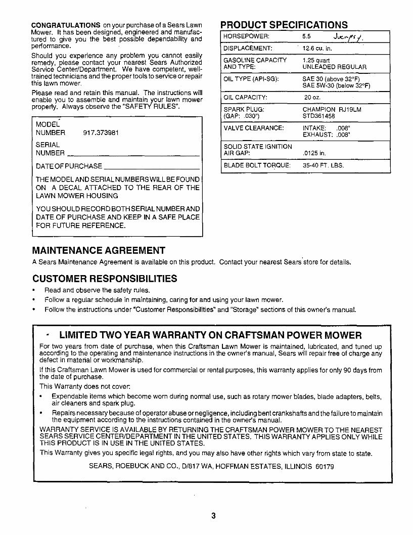
PRODUCT SPECIFICATIONS
HORSEPOWER: 5.5 J_-f_i,
DISPLACEMENT: 12.6 cu. in.
GASOLINE CAPACITY 1.25 quartAND TYPE: UNLEADED REGULAR
OIL TYPE (API-SG): SAE 30 (above 32°F)SAE 5W-30 (below 32°F)
OIL CAPACITY: 20 oz.
;PARK PLUG: CHAMPION RJ19LMGAP: .030") STD361458
VALVE CLEARANCE: INTAKE: .008"EXHAUST: .008"
SOLID STATE IGNITIONA[R GAP: .0125 in.
BLADE BOLT TORQUE: 35-40 FT. LBS.
MAINTENANCE AGREEMENTA Sears Maintenance Agreement is available on this product. Contact your nearest Sears store for details.
CUSTOMER RESPONSIBILITIES• Read and observe the safety rules.
Follow a regular schedule in maintaining, caring for and using your lawn mower.
• Follow the instructions under "Customer Responsibilities" and "Storage" sections of this owner's manual.
LIMITED TWO YEAR WARRANTY ON CRAFTSMAN POWER MOWERFor two years from date of purchase, when this Craftsman Lawn Mower is maintained, lubricated, and tuned upaccording to the operating and maintenance instructions in the owner's manual, Sears will repair free of charge anydefect in material or workmanship.
If this Craftsman Lawn Mower is used for commercial or rental purposes, this warranty applies for only 90 days fromthe date of purchase.
This Warranty does not cover:
• Expendable items which become worn during normal use, such as rotary mower blades, blade adapters, belts,air cleaners and spark plug.
• Repairs necessary because of operator abuse or negligence, including bent crankshafts and the failure to maintainthe equipment according to the instructions contained in the owner's manual.
WARRANTY SERVICE IS AVAILABLE BY RETURNING THE CRAFTSMAN POWER MOWER TO THE NEARESTSEARS SERVICE CENTER/DEPARTMENT IN THE UNITED STATES. THIS WARRANTY APPLIES ONLY WHILETHIS PRODUCT IS IN USE IN THE UNITED STATES.
This Warranty gives you specific legal rights, and you may also have other rights which vary from state to state.
SEARS, ROEBUCK AND CO., D/817 WA, HOFFMAN ESTATES, ILLINOIS 60179
3
TABLE OF CONTENTS
SAFETY RULES ............................................. ............... 2PRODUCT SPECIFICATIONS ....................................... 3CUSTOMER RESPONSIBILITIES ..................... 3, 12-14WARRANTY ................................................................... 3ASSEMBLY .................................................................... 6OPERATION .................................................................. 8
MAINTENANCE SCHEDULE .............. ,....................... 12SERVICE AND ADJUSTMENTS ................................. 15STORAGE .................................................................... 17TROUBLESHOOTING ................................................. 27REPAIR PARTS - LAWN MOWER ........................ 18-22REPAIR PARTS - ENGINE ..................................... 23-25PARTS ORDERING/SERVICE ................ BACK COVER
INDEXA
Accessories.......................................... 5Adjustments:
Carburetor................................... 16EngineSpeed .............................. 16HandleHeight.............................. 16Heightof Cut ................................. 9
Air Filter:Replacement ............................... 14Service ........................................ 14
Assembly.............................................. 6
BBlade:
Sharpening .................................. 13Replacement ............................... 13
CControls:
DriveControl ................................. 9EngineZone Control ..................... 9EngineSpeed Control ................... 9OperatorPresenceControlBar..... 8
CustomerResponsibilities......... 3, 12-14Air Filter.............. :........................ 14Blade Care/Replacement............ 13Driv_eWheels ............................... 13Engine ......................................... 14Lubrication................................... 14Spark Plug................................... 14
CuttingLevels....................................... 9
EEngine:
Air Filter....................................... 14Oil Change ..................................14Oil Level ......................................14Oil Type ....................................... 14Starting........................................10Stopping......................................10Storage........................................17
FFuel:
Capacity ........................................3Storage........................................17Type ............................................10
LLubrication:
Engine......................................... 14Lawn Mower ................................12
MMaintenanceAgreement ......................3Maintenance Schedule ....................... 12Mowing Tips ....................................... 11
Oil:
O
Engine .........................................10Storage ........................................17
Operation:Drive Control ................................. 9Engine Control ............................... 9Grass Catcher ............................. 10Mower ........................................... 9OperatorPresence Control Bar .....9
Options:Accessories ................................... 5
RRepair Parts:
Engine....................................23-25LawnMower........................... 18-22
Responsibilities,Customer........3, 12-14
SSafety Rules ......................................... 2Service and Adjustments .................... 15
Carburetor ................................... 16Engine Speed .............................. 16Handle ......................................... 16
Spark Plug.......................................... 14Specifications ....................................... 3Speed Control:
Engine ......................................... 10Starting the Engine............................. 10Stopping the Engine ........................... 10Storage ............................................... 17
TTroubleshootingChart........................ 27
WWarranty ............................................... 3
4
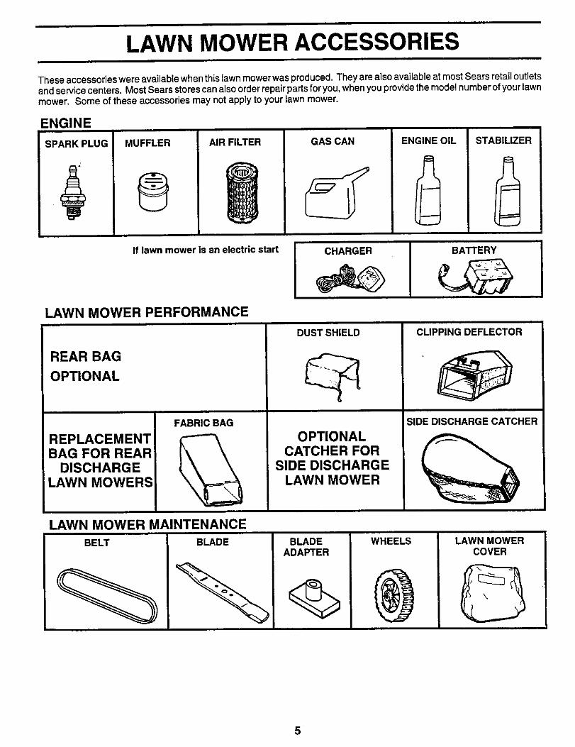
LAWN MOWER ACCESSORIES
These accessories were available when this lawn mower was produced. They are also available at most Sears retail outletsand service centers. Most Sears stores can also order repair parts for you, when you provide the model number of your lawnmower. Some of these accessories may not apply to your lawn mower.
ENGINE
SPARK PLUG MUFFLER
®AIR FILTER GAS CAN ENGINE OIL STABILIZER
If lawn mower is an electric start CHARGER BA'n'ERY
LAWN MOWER PERFORMANCE
REAR BAG
OPTIONAL
REPLACEMENTBAG FOR REAR
DISCHARGELAWN MOWERS:
FABRIC BAG
LAWN MOWER MAINTENANCE
DUST SHIELD
OPTIONALCATCHER FOR
SIDE DISCHARGELAWN MOWER
CLIPPING DEFLECTOR
SIDE DISCHARGECATCHER
5
ASSEMBLYRead these instructions and this manual in its entiretybefore you attempt to assemble or operate your new lawnmower. Your new lawn mower has been assembled at thefactory with the exception of those parts left unassembledfor shipping purposes. To ensure safe and proper opera-tion of your lawn mower, all parts and hardware youassemble must be tightened securely. Use the correcttools as necessary to ensure proper tightness. All partssuch as nuts, washers, bolts, etc., necessary to completethe assembly have been placed in the parts bag.
TO REMOVE LAWN MOWER FROMCARTON
Remove loose parts included with mower.
• Cut down two end corners of carton and lay end paneldown flat.
• Remove all packing materials except padding betweenupper and lower handle and padding holding operatorpresence control bar to upper handle.
• Roll lawn mower out of carton and check carton thor-oughly for additional loose parts.
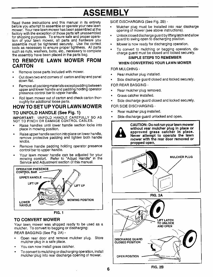
HOWTO SET UPYOUR LAWN MOWER
TO UNFOLD HANDLE (See Fig. 1)IMPORTANT: UNFOLD HANDLE CAREFULLY SO ASNOT TO PINCH OR DAMAGE CONTROL CABLES.
• Raise handles until lower handle section locks intoplace in mowing position.
• Raise upper handle section into place on lower handle,remove protective padding and tighten both handleknobs.
Remove handle padding holding operator presencecontrol bar to upper handle.
Your lawn mower handle can be adjusted for yourmowing comfort. Refer to "Adjust Handle" in theService and Adjustment section of this manual.
OPERATOR PRESENCE
CONTROL BAR
UPPER HA_
LIFT UPLIFT UP
LOWERHANDLE
MOWING POSITION
SIDE DISCHARGING (See Fig. 2B) -
• Mulcher plug must be installed into rear dischargeopening of mower (see above instructions).
• Unlock closed discharge guard by lifting latch and allowguard to swing open to discharging position.
• Mower is now ready for discharging operation.
• To convert to mulching or bagging operation, dis-charge guard must be closed and locked securely.
SIMPLE STEPS TO REMEMBER
WHEN CONVERTING YOUR LAWN MOWER
FOR MULCHING -
• Rear mulcher plug installed.
• Side discharge guard closed and locked securely.
FOR REAR BAGGING -
• Rear mulcher plug removed.
• Grass catcher installed.
• Side discharge guard closed and locked securely,
FOR SiDE DISCHARGING -
Rear mulcher plug installed.
• Side discharge guard unlocked and open.
CAUTION: Do not run your lawn mowerwithout rear mulcher plug in place orapproved grass catcher in place.Never attempt to operate the lawnmower with the rear door removed orpropped open.
MULCHER PLUG
FIG. 2A
FIG. 1
TO CONVERT MOWER
Your lawn mower was shipped ready to be used as amulcher. To convert to bagging or discharging:REAR BAGGING (See Fig. 2A) -
• Open rear door and remove mulcher plug. Storemulcher plug in a safe place.
You can now install grass catcher.
• To convert to mulching or discharging operation, installmulcher plug into rear discharge opening of mower.
DISCHARGE GUARDCLOSED POSITION
OPEN POSITION
LIFT LATCHTO UNLOCKAND OPEN
6 FIG. 2B
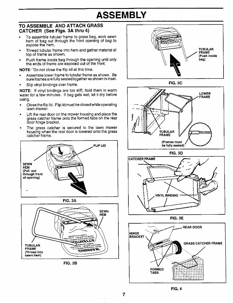
ASSEMBLYTO ASSEMBLE AND A'I'rACH GRASS
CATCHER (See Figs. 3A thru 4)• To assemble tubular frame to grass bag, work sewn
hem of bag out through the front opening of bag toexpose the hem.
• Thread tubular frame into hem and gather material attop of frame as shown.
• Push frame inside bag through the opening until onlythe ends of frame are exposed out of the front.
NOTE:" Do not close the flip lid at this time.• Assemble lower frame to tubular frame as shown. Be
sure frames are fully seated together as shown in inset.
• Slip vinyl bindings over frame.
NOTE: If vinyl bindings are too stiff, hold them in warmwater for a few minutes. If bag gets wet, let it dry beforeusing.
• Close the flip lid. Flip lid must be closed while operatinglawn mower.
Lift the rear door on the mower housing and place thedgrasscatcher frame onto the formed tabs on the rearoor hinge bracket.
The grass catcher is secured to the lawn mowerhousing when the rear door is lowered onto the grasscatcher frame.
FLIP LID
SEWNHEM(Pull outthrough frontof opening)
FIG. 3A
SEWNHEM
TUBULARFRAME(Thread intosewn hem)
_ TUBULAR
FIG. 3C
LOWER
TUBULARFRAME
(Frames mustbe fully seated)
FIG. 3D
CATCHERFRAME
\
FIG. 3E
HINGE
GRABS CATCHER FRAME
FIG. 3B
FORMEDTABS
7
FIG. 4
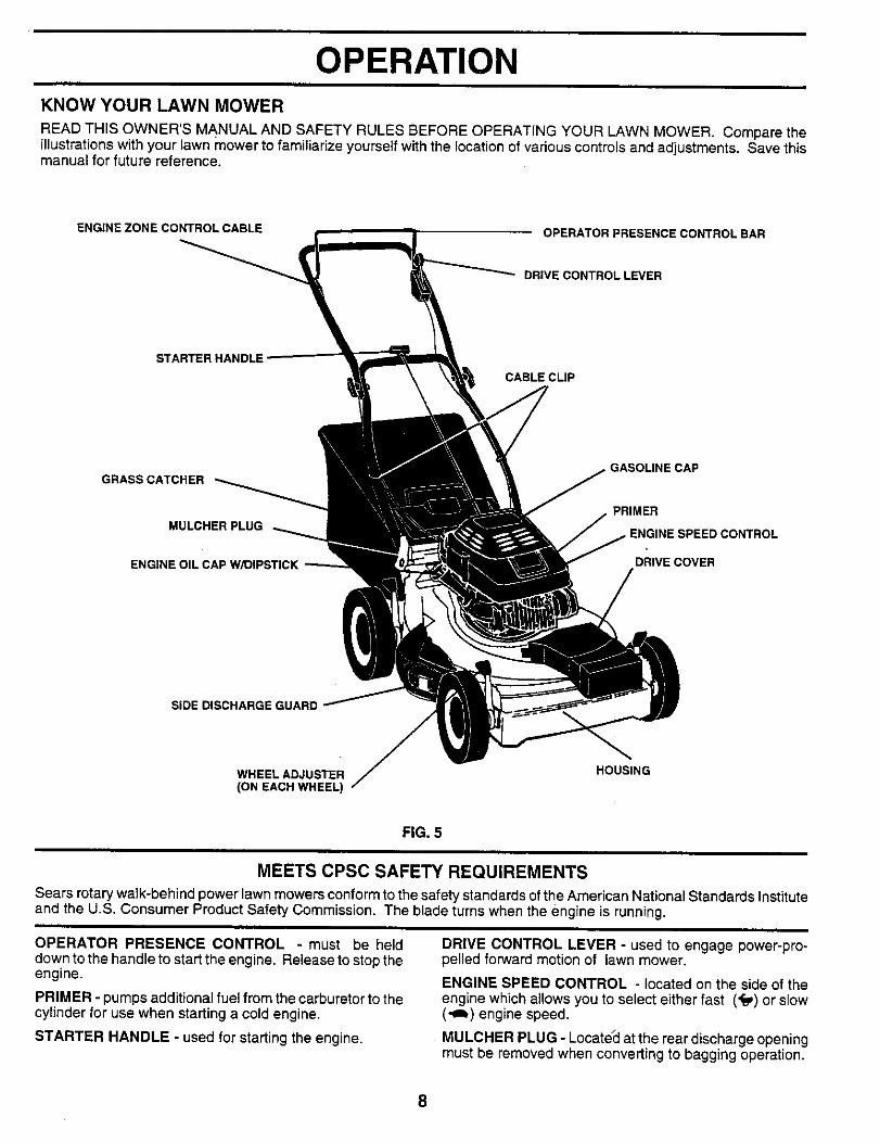
OPERATIONKNOW YOUR LAWN MOWER
READ THIS OWNER'S MANUAL AND SAFETY RULES BEFORE OPERATING YOUR LAWN MOWER. Compare theillustrations with your lawn mower to familiarize yourself with the location of various controls and adjustments. Save thismanual for future reference.
ENGINE ZONECONTROLCABLE OPERATOR PRESENCE CONTROL BAR
DRIVE CONTROL LEVER
STARTER HANDLE
CABLE CLIP
GRASS CATCHER
MULCHER PLUG
ENGINE OIL CAP WfDIPSTICK
GASOLINE CAP
PRIMER
DRIVE COVER
SiDE DISCHARGE GUARD
WHEEL ADJUSTER(ON EACH WHEEL)
HOUSING
FIG. 5
MEETS CPSC SAFETY REQUIREMENTS
Sears rotary walk-behind power lawn mowers conform to the safety standards of the American National Standards Instituteand the U.S. Consumer Product Safety Commission. The blade turns when the engine is running.
OPERATOR PRESENCE CONTROL - must be helddown to the handle to start the engine. Release to stop theengine.
PRIMER - pumps additional fuel from the carburetor to thecylinder for use when starting a cold engine.
STARTER HANDLE - used for starting the engine.
DRIVE CONTROL LEVER - used to engage power-pro-pelled forward motion of lawn mower.
ENGINE SPEED CONTROL - located on the side of theengine which allows you to select either fast ('f_) or slow(,_) engine speed.
MULCHER PLUG - Locate_clat the rear discharge openingmust be removed when converting to bagging operation.
8
OPERATION
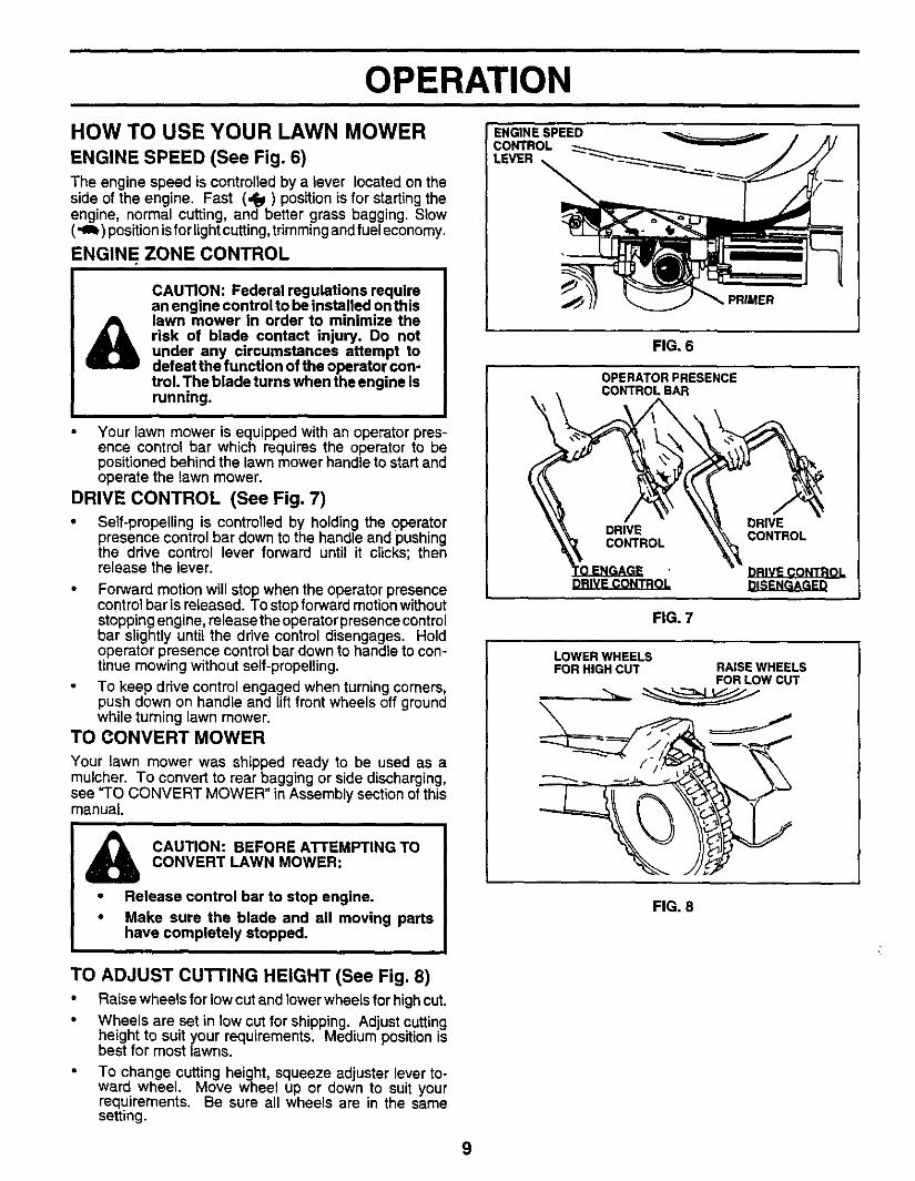
HOW TO USE YOUR LAWN MOWERENGINE SPEED (See Fig. 6)
The engine speed is controlledby a lever locatedon thesideof the engine. Fast (,Pep)positionis for startingtheengine, normal cutting,and better grass bagging.Slow(_ ) positionisfor lightcutting,trimmingandfuel economy.
ENGINE ZONE CONTROL
&CAUTION: Federal regulations requirean engine control to be installed on thislawn mower in order to minimize therisk of blade contact injury, Do notunder any circumstances attempt todefeat the function of the operator con-trol. The blade turns when the engine isrunning.
• Your lawn mower is equipped with an operator pres-ence control bar which requires the operator to bepositioned behind the lawn mower handle to start andoperate the lawn mower.
DRIVE CONTROL (See Fig. 7)
• Self-propelling is controlled by holding the operatorpresence control bar down to the handle and pushingthe drive control lever forward until it clicks; thenrelease the lever.
• Forward motion will stop when the operator presencecontrol bar is released. To stop forward motion withoutstopping engine, release the operator presence controlbar slightly until the drive control disengages. Holdoperator presence control bar down to handle to con-tinue mowing without self-propelling.
To keep drive control engaged when turning corners,push down on handle and lift front wheels off groundwhile turning lawn mower.
TO CONVERT MOWER
Your lawn mower was shipped ready to be used as amulcher. To convert to rear bagging or side discharging,see "TO CONVERT MOWER" in Assembly section of thismanual.
CAUTION: BEFORE ATTEMPTING TOCONVERT LAWN MOWER:
• Release control bar to stop engine.
• Make sure the blade and all moving partshave completely stopped.
TO ADJUST cu'n'ING HEIGHT (See Fig. 8)• Raise wheels for low cut and lower wheels for high cut.
• Wheels are set in low cut for shipping. Adjust cuttingheight to suit your requirements. Medium position isbest for most lawns.
To change cutting height, squeeze adjuster lever to-ward wheel. Move wheel up or down to suit yourrequirements. Be sure all wheels are in the samesetting.
ENGINE SPEEDCONTROL
LEVER
FIG. 6
OPERATOR PRESENCECONTROLBAR
DRIVEDRIVE CONTROLCONTROL
LOWER WHEELSFOR HIGHCUT RAISE WHEELS
FOR LOW CUT
FIG. 8
9
OPERATION
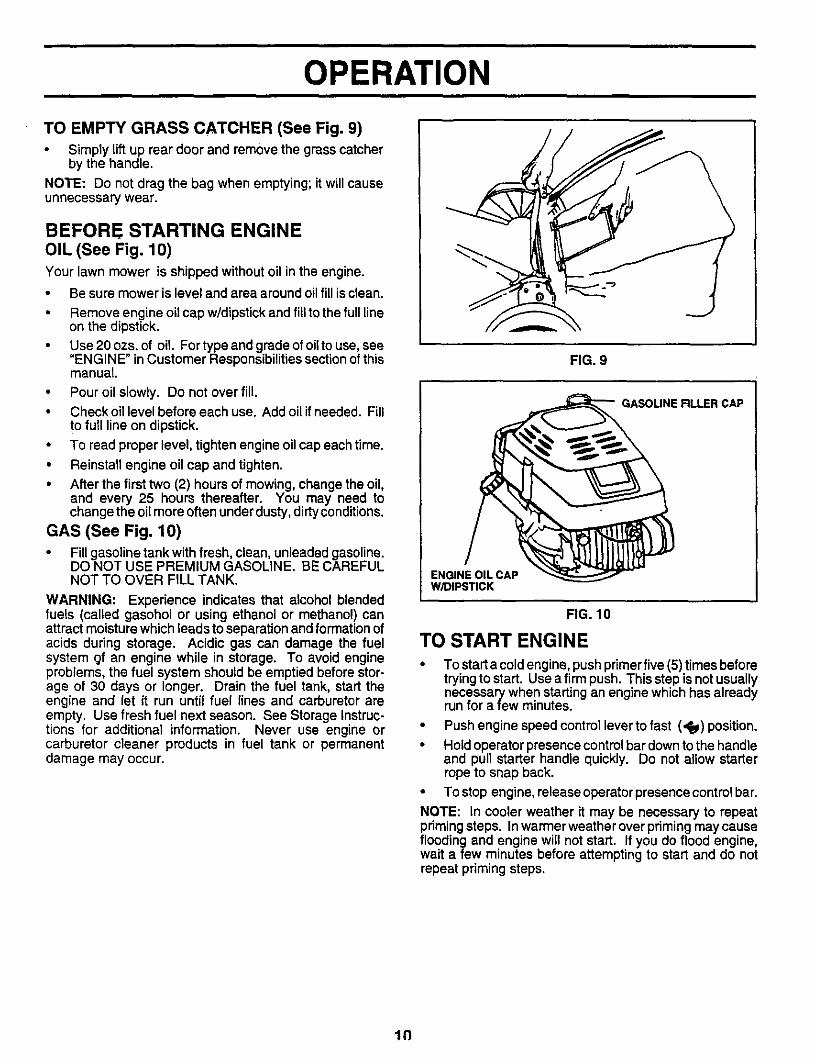
TO EMPTY GRASS CATCHER (See Fig. 9)• Simply lift up rear door and remove the grass catcher
by the handle.
NOTE: Do not drag the bag when emptying; it will causeunnecessary wear.
BEFORE STARTING ENGINEOIL (See Fig. 10)Your lawn mower is shipped without oil in the engine.
Be sure mower is level and area around oil fill is clean.
Remove engine oit cap w/dipstick and fill to the full lineon the dipstick.
Use 20 ozs. of oil. For type and grade of oil to use, see"ENGINE" in Customer Responsibilities section of thismanual.
• Pour oil slowly. Do not over fill.• Check oil level before each use. Add oil if needed. Fill
to full line on dipstick.
• To read proper level, tighten engine oil cap each time.
• Reinstall engine oil cap and tighten.
• After the first two (2) hours of mowing, change the oil,and every 25 hours thereafter. You may need tochange the oil more often under dusty, dirty conditions.
GAS (See Fig. 10)• Fill gasoline tank with fresh, clean, unleaded gasoline.
DO NOT USE PREMIUM GASOLINE. BE CAREFULNOT TO OVER FILL TANK.
WARNING: Experience indicates that alcohol blendedfuels (called gasohol or using ethanol or methanol) canattract moisture which leads to separation and formation ofacids during storage. Acidic gas can damage the fuelsystem gf an engine while in storage. To avoid engineproblems, the fuel system should be emptied before stor-age of 30 days or longer. Drain the fuel tank, start theengine and let it run until fuel lines and carburetor areempty. Use fresh fuel next season. See Storage Instruc-tions for additional information. Never use engine orcarburetor cleaner products in fuel tank or permanentdamage may occur.
FIG. 9
GASOLINEFILLERCAP
ENGINE OIL CAPW/DIPSTICK
FIG. 10
TO START ENGINE• To start a cold engine, push primer five (5) times before
trying to start. Use a firm push. This step is not usuallynecessary when starting an engine which has alreadyrun for afew minutes.
• Push engine speed control lever to fast (,,_) position.
• Hold operator presence control bar down to the handleand pull starter handle quickly. Do not allow starterrope to snap back.
• To stop engine, release operator presence control bar.
NOTE: In cooler weather it may be necessary to repeatpriming steps. In warmerweather over priming maycauseflooding and engine will not start. If you do flood engine,wait a few minutes before attempting to start and do notrepeat priming steps.
113
OPERATION
MOWING TIPSUndercertain conditions, such as very tall grass, it maybe necessary to raise the height of cut to reducepushing effort and to keep from overloading the engineand leaving clumps of grass clippings.
For extremely heavy cutting, reduce the width of cut byoverlapping previously cut path and mow slowly.
For better grass bagging and most cutting conditions,the engine speed should be set in the fast (,_) posi-tion.
When using a rear discharge lawn mower in moist,heavy grass, clumps of cut grass may not enter thegrass catcher. Reduce ground speed (pushing speed)and/or runthe lawn mower ove rthe area a seco ndtime.
If a trail of clippings is left on the right side of a reardischarge mower, mow in a clockwise direction with asmall overlap to collect the clippings on the next pass.
Pores incloth grass catchers can become filled with dirtand dust with use and catchers will collect less grass.To prevent this, regularly hose catcher off with waterand let dry before using.
Keep top of engine around starter clear and clean ofgrass clippings and chaff. This will help engine air flowand extend engine life.
MAX 1/3
FIG. 11
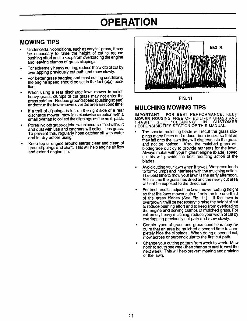
MULCHING MOWING TIPSIMPORTANT: FOR BEST PERFORMANCE, KEEPMOWER HOUSING FREE OF BUILT-UP GRASS ANDTRASH. SEE =CLEANING" IN CUSTOMERRESPONSIBILITIES SECTION OF THIS MANUAL.
The special mulching blade will recut the grass clip-pings many times and reduce them in size so that asthey fall onto the lawn they will disperse into the grassand not be noticed. Also, the mulched grass willbiodegrade quickly to provide nutrients for the lawn.Always mulch with your highest engine (blade) speedas this will provide the best recutting action of theblades.
• Avoid cutting your lawn when it is wet. Wet grass tendsto form clumps and interferes with the mulching action.The best time to mow your lawn is the early afternoon.At this time the grass has dried and the newly cut areawill not be exposed to the direct sun.
• For best results, adjust the lawn mower cutting heightso that the lawn mower cuts off only the tcp one-thirdof the grass blades (See Fig. 11). If the lawn isovergrown it will be necessary to raise the height of cutto reduce pushing effort and to keep from overloadingthe engine and leaving clumps of mulched grass. Forextremely heavy mulching, reduce your width of cut byoverlapping previously cut path and mow slowly.
• Certain types of grass and grass conditions may re-quire that an area be mulched a second time to com-pletely hide the clippings. When doing a second cut,mow across or perpendicular to the first cut path.
• Changeyourcuttingpattemfromweektoweek. Mownorth to south one week then change to east to west thenext week. This will help prevent matting and grainingof the lawn.
11
CUSTOMER RESPONSIBILITIES
FILL IN DATES " _ _-,_'/>'n_-_'/_-,,_'-,_"- ¢_'_J_"ASYouCOMP,ETEREGULAR SERVICE _/_ _£-q(_£'£._ SERVICE DATES
Check for Loose Fasteners _
M Clean/Inspect Grass Catcher V'_(If Equipped) IfClean Lawn Mower
W Drive WheelsInspect/Clean(Self-Propelled Mowers) V'
R Sharpen/Replace Mower Blade I/'3
Lubrication Chart ikf If
Clean Battery/RechargetElectric Start Mowers / If V'4
RE Check Engine Oil Level If I_Change Engine Oil _ 1_1.2
G Clean Air Filter _2Inspect Muffler
NE Replace Spark Plug! Replace Air Filter Paper Cartridge 2
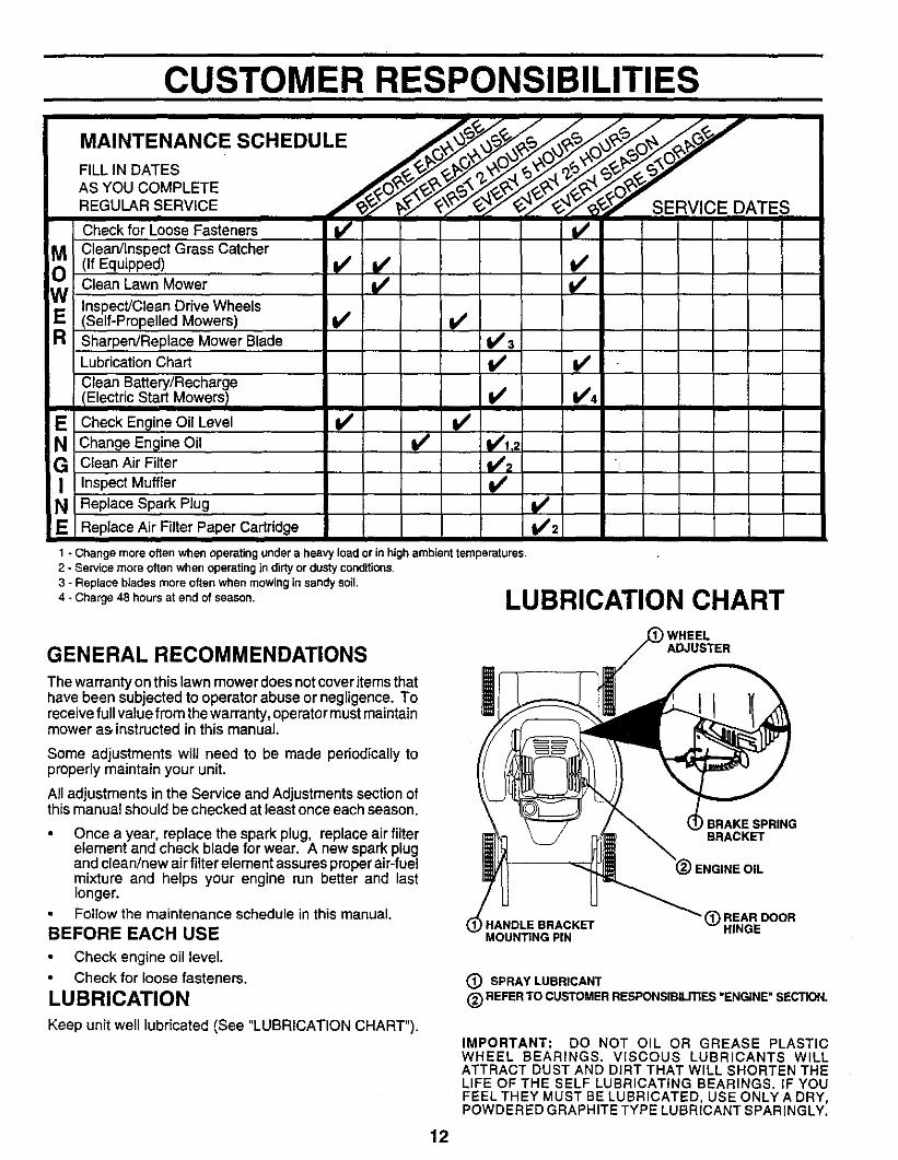
1 - Change more often when operating under a heavy load or in high ambient temperatures.2 - Service more often when operating in dirty or dusty condfflons,3 - Replace blades more often when mowing in sandy soil.
4-Charge 48 hours at end of season. LUBRICATION CHART
GENERAL RECOMMENDATIONS
The warranty on this lawn mower does not cover items thathave been subjected to operator abuse or negligence. Toreceive full value from the warranty, operator must maintainmower as instructed in this manual,
Some adjustments will need to be made periodically toproperly maintain your unit.
All adjustments in the Service and Adjustments section ofthis manual should be checked at least once each season.
• Once a year, replace the spark plug, replace air filterelement and check blade for wear. A new spark plugand clean/new air filter element assures proper air-fuelmixture and helps your engine run better and lastlonger.Follow the maintenance schedule in this manual.
BEFORE EACH USE
• Check engine oil level.Check for loose fasteners.
LUBRICATION
Keep unit well lubricated (See "LUBRICATION CHART").
) WHEELADJUSTER
BRAKE SPRINGBRACKET
i ENGINE OIL
HANDLE BRACKETMOUNTING PIN
_) REAR DOORHINGE
(_) SPRAY LUBRICANT
(_ REFER TO CUSTOMER RESPONSIBILITIES "ENGINE" SECTION.
IMPORTANT: DO NOT OIL OR GREASE PLASTICWHEEL BEARINGS. VISCOUS LUBRICANTS WILLATTRACT DUST AND DIRT THAT WILL SHORTEN THELIFE OF THE SELF LUBRICATING BEARINGS. IF YOUFEEL THEY MUST BE LUBRICATED, USE ONLYA DRY,POWDERED GRAPHITE TYPE LUBRICANT SPARINGLY.
12
CUSTOMER RESPONSIBILITIESLAWN MOWERAlways observe safety rules when performing any mainte-nance.
TIRES
• Keep tires free of gasoline, oil, or insectcontrol chemi-cals which can harm rubber.
• Avoid stumps, stones, deep ruts, sharp objects andother hazards that may cause tire damage.
BLADE CARE
For best results, mower blade must be kept sharp. Re-place bent or damaged blades.
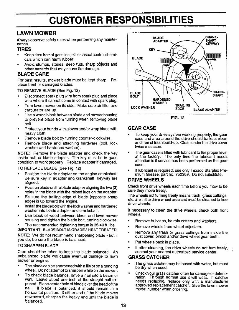
TO REMOVE BLADE (See Fig. 12)
• Disconnect spark plug wire from spark plug and placewire where it cannot come in contact with spark plug.
• Turn lawn mower on its side. Make sure air filter andcarburetor are up.
• Use a wood block between blade and mower housingto prevent blade from turning when removing bladebolt.
• Protect your hands with gloves and/orwrap blade withheavy cloth.
• Remove blade bolt by turning counter-clockwise.Remove blade and attaching hardware (bolt, lockwasher and i_ardened washer).
NOTE: Remove the blade adapter and check the keyinside hub of blade adapter. The key must be in goodcondition to work properly. Replace adapter if damaged•
TO REPLACE BLADE (See Fig. 12)
• Position the blade adapter on the engine crankshaft•Be sure key in adapter and crankshaft keyway arealigned.
• Position blade on the blade adapter aligning the two (2)holes in the blade with the raised lugs on the adapter.
• B_ sure the trailing edge of blade (opposite sharpedge) is up toward the engine.
• Install the blade bolt with the Iockwasher and hardenedwasher into blade adapter and crankshaft.
• Use block of wood between blade and lawn mowerhousing and tighten the blade bolt, turning clockwise.
• The recommended tightening torque is 35-40 ft. Ibs.IMPORTANT: BLADE BOLT IS GRADE 8 HEAT TREATED.
NOTE: We do not recommend sharpening blade - but ifyou do, be sure the blade is balanced.
TO SHARPEN BLADE
Care should be taken to keep the blade balanced. Anunbalanced blade will cause eventual damage to lawnmower or engine.
The blade can be sharpened with a file or on a g rindingwheel. Do not attempt to sharpen while on the mower.
• To check blade balance, drive a nail into a beam orwall. Leave about one inch of the straight nail ex-posed. Place center hole of blade over the head of thenail. If blade is balanced, it should remain in ahorizontal position. If either end of the blade movesdownward, sharpen the heavy end until the blade isbalanced.
BLADE
BLADE
SHAFTHARDENEDWASHER
TRAILINGLOCK WASHER EDGE BLADE ADAPTER
FIG. 12
GEAR CASE
• To keep your drive system working properly, the gearcase and area around the drive should be kept cleanand free of trash build-up. Clean under the drive covertwice a season.
• The gear case is filled with lubricant to the proper levelat the factory. The only time the lubricant needsattention is if service has been performed on the gearcase.
• If lubricant is required, use only Texaco Starplex Pre-mium Grease, part no. 750369. Do not substitute.
DRIVE WHEELS
Check front drive wheels each time before you mow to besure they move freely.The wheels not turning freely means trash, grass cuttings,etc. are in the drive wheel area and must be cleaned to freedrive wheels.
If necessary to clean the drive wheels, check both frontwheels.
• Remove hubcaps, hairpin cotters and washers.
• Remove wheels from wheel adjusters.
• Remove any trash or grass cuttings from inside thedust cover, pinion and/or drive wheel gear teeth.
• Put wheels back in place.
• If after cleaning, the drive wheels do not tum freely,contact your nearest authorized service center.
GRASS CATCHER
The grass catcher may be hosed with water, but mustbe dry when used.
Check your grass catcher often for damage or deterio-ration. Through normal use it will wear. If catcherneeds replacing, replace only with a manufacturerapproved replacement catcher. Give the lawn mowermodel number when ordering•
13
CUSTOMER RESPONSIBILITIES
ENGINELUBRICATION
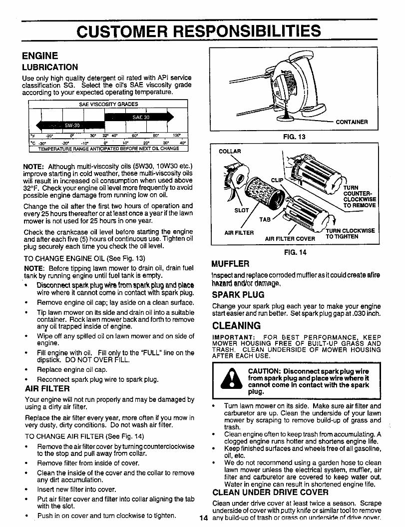
Use only high quality detergent oil rated with API serviceclassification SG. Select the oil's SAE viscosity gradeaccording to your expected operating temperature.
SAE VISCOSITY GRADES
-30" -20" -I0" 0" 10" 20" 30°TEMPERATURE RANGE ANTICIPATED BEFORE NEXT OIL CHANGE
NOTE: Although multi-viscosity oils (5W30, 10W30 etc.)improve starting in cold weather, these multi-viscosity oilswill result in increased oil consumption when used above32°F. Check your engine oil level more frequently to avoidpossible engine damage from running low on oil.
Change the oil after the first two hours of operation andevery 25 hours thereafter or at least once a year if the lawnmower is not used for 25 hours in one year.
Check the crankcase oil level before starting the engineand after each five (5) hours of continuous use. Tighten oilplug securely each time you check the oil level.
TO CHANGE ENGINE OIL (See Fig. 13)
NOTE: Before tipping lawn mower to drain oil, drain fuel•tank by running engine until fuel tank is empty.
Disconnect spark plug wlm Imm sp_,rkplug _nd pllcowire where it cannot come in contact with spark plug.
• Remove engine oil cap; lay aside on a clean surface,
• Tip lawn mower on its side and drain oil into a suitablecontainer. Rock lawn mower back and forth to removean}, oil trapped inside of engine,
• Wipe off any spilled oil on lawn mower and on side ofengine.
• Fill engine with oil. Fill only to the "FULL" line on thedipstick. DO NOT OVER FILL.
• Replace engine oil cap.
• Reconnect spark plug wire to spark plug.AIR FILTER
Your engine will not run properly and may be damaged byusing a dirty air filter.
Replace the air filter every year, more often if you mow invery dusty, dirty conditions. Do not wash air filter.
TO CHANGE AIR FILTER (See Fig. 14)
• Remove the air filter cover by turning counterclockwiseto the stop and pull away from collar.
• Remove filter from inside of cover.
• Clean the inside of the cover and the collar to removeany dirt accumulation.
• Insert new tilter into cover.
• Put air filter cover and filter into collar aligning the tabwith the slot.
• Push in on cover and turn clockwise to tighten.
CONTAINER
FIG. 13
COLLAR
SLOT
COUNTER-CLOCKWISETO REMOVE
AIR FILTERAIR FILTER COVER TO TIGHTEN
FIG, 14
MUFFLER
inspect and replace corroded muffler as itcould create afireh_z_rd_ncl/orcl_m_g_,
SPARK PLUG
Change your spark plug each year to make your enginestart easier and run better. Set spark plug gap at.030 inch.
CLEANINGIMPORTANT: FOR BEST PERFORMANCE, KEEPMOWER HOUSING FREE OF BUILT-UP GRASS ANDTRASH. CLEAN UNDERSIDE OF MOWER HOUSINGAFTER EACH USE,
CAUTION: Disconnect spark plug wire I
from spark plug and place wire where itcannot come in contact with the sparkplug.
• Turn lawn mower on its side. Make sure air filter andcarburetor are up. Clean the underside of your lawnmower by scraping to remove build-up of grass andtrash.
• Clean engine often to keep trash from accumulating. Aclogged engine runs hotter and shortens engine life.
• Keep finished surfaces and wheels free of all gasoline,oil, etc,
• We do not recommend using a garden hose to cleanlawn mower unless the electrical system, muffler, airfilter and carburetor are covered to keep water out.Water in engine can result in shortened engine life.
CLEAN UNDER DRIVE COVER
Clean under drive cover at least twice a season. Scrapeunderside of cover with putty knife or similar tool to remove
14 any build-up of trash or crass on und_rRid_ of drive=P.t_v_r.
SERVICE AND ADJUSTMENTS
CAUTION" BEFORE PERFORMING ANY SERVICE OR ADJUSTMENTS:
! Release control bar.Make sure the blade and all moving parts have completely stopped.
• Disconnect spark plug wire from spark plug and place where it cannot come in contact with plug.
lAWN MOWER
TO ADJUST CU'I-rlNG HEIGHT
See 'TO ADJUST CUFFING HEIGHT" in the Operationsection of this manual.
REAR DEFLECTOR
The rear deflector, attached between the rear wheels ofyour lawn mower, is provided to minimize the possibilitythat objects will be thrown out the rear of the lawn mowerinto the operator's mowing position. If the rear deflectorbecomes damaged, it should be replaced.
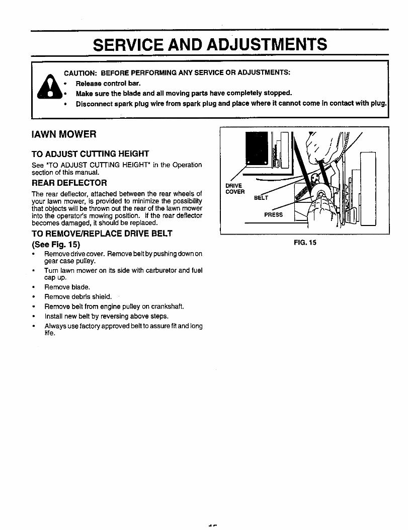
TO REMOVE/REPLACE DRIVE BELT
(See Fig. 15)• Remove drive cover. Remove belt by pushingdown on
gear case pulley.Turn lawn mower on its side with carburetor and fuelcap up.
• Remove blade.
• Remove debris shield.
Remove belt from engine pulley on crankshaft.
Install new belt by reversing above steps.
Always use factory approved belt to assure fit and longlife.
DRIVECOVER
BELT
PRESS
FIG. 15
SERVICE AND ADJUSTMENTS
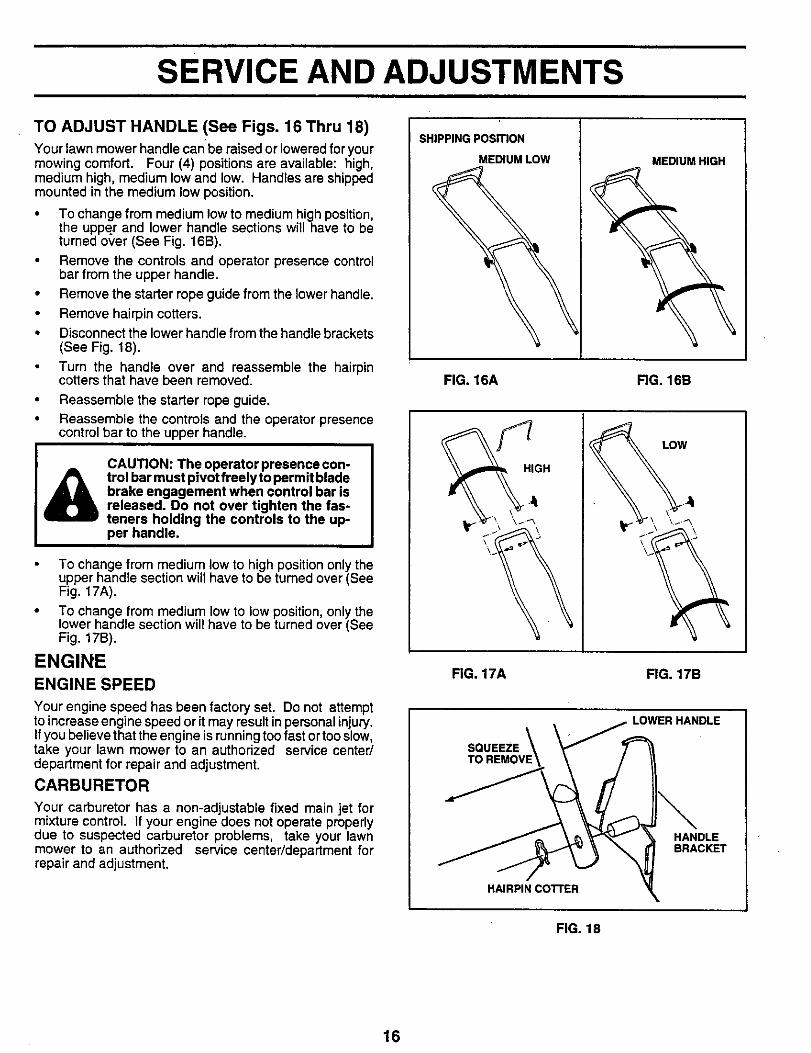
TO ADJUST HANDLE (See Figs. 16 Thru 18)Your lawn mower handle canbe raised or lowered foryourmowing comfort. Four (4) positions are available: high,medium high, medium low and low. Handles are shippedmounted in the medium low position.
• To change from medium low to medium high position,the upper and lower handle sections will have to beturned over (See Fig. 16B).
Remove the controls and operator presence controlbar from the upper handle.
• Remove the starter rope guide from the lower handle.
• Remove hairpin cotters.
• Disconnect the lower handle from the handle brackets(See Fig. 18).
Turn the handle over and reassemble the hairpincotters that have been removed.
• Reassemble the starter rope guide.
• Reassemble the controls and the operator presencecontrol bar to the upper handle.
&CAUTION: The operator presence con-trol bar must pivot freely to permit bladebrake engagement when control bar isreleased. Do not over tighten the fas-teners holding the controls to the up-per handle.
To change from medium low to high position only theupper handle section will have to be turned over (SeeFig. 17A).
To change from medium low to low position, only thelower handle section will have to be turned over (SeeFig. 17B).
ENGINEENGINE SPEED
Your engine speed has been factory set. Do not attemptto increase engine speed or it may result in personal injury.If you believe that the engine is running too fast or too slow,take your lawn mower to an authorized service center/department for repair and adjustment.
CARBURETOR
Your carburetor has a non-adjustable fixed main jet formixture control. If your engine does not operate properlydue to suspected carburetor problems, take your lawnmower to an authorized service center/department forrepair and adjustment.
SHIPPING PosmoN
MEDIUM LOW MEDIUM HIGH
FIG. 16A FIG. 16B
FHIGH
LOW
FIG. 17A FIG. 17B
LOWERHANDLE
SQUEEZE
HANDLEBRACKET
HAIRPIN COI"FER
FIG. 18
16
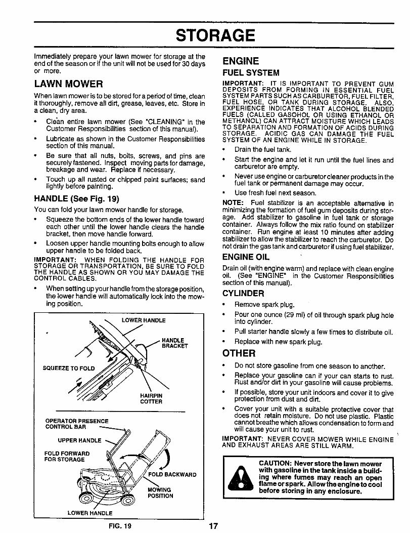
STORAGE
ENGINEImmediately prepare your lawn mower for storage at theend of the season or if the unit will not be used for 30 daysor more.
LAWN MOWERWhen lawn mower is to be stored for a period of time, cleanit thoroughly, remove all dirt, grease, leaves, etc. Store ina clean, dry area.
• Clean entire lawn mower (See "CLEANING" in theCustomer Responsibilities section of this manual).
• Lubricate as shown in the Customer Responsibilitiessection of this manual.
• Be sure that all nuts, bolts, screws, and pins aresecurelyfastened. Inspect movingparfsfordamage,breakage and wear. Replace if necessary.
• Touch up all rusted or chipped paint surfaces; sandlightly before painting.
HANDLE (See Fig. 19)
You can fold your lawn mower handle for storage.
• Squeeze the bottom ends of the lower handle towardeach other until the lower handle clears the handlebracket, then move handle forward.
• Loosen upper handle mounting bolts enough to allowupper handle to be folded back.
IMPORTANT: WHEN FOLDING THE HANDLE FORSTORAGE OR TRANSPORTATION, BE SURE TO FOLDTHE HANDLE AS SHOWN OR YOU MAY DAMAGE THECONTROL CABLES.
• When setting upyour handle from the storage position,the lower handle will automatically lock into the mow-ing position.
LOWER HANDLE
BRACKET
SQUEEZE TO FOLD
HAIRPINCOTTER
OPERATOR PRESENCE
CONTROL eAR
UPPER HANDLE _ _7/.._//_'_"_
FoRFOLDFORWARDsToRAGE /_,_,.--" _f__YJ
_'_"'_'_ h" "_
LOWER HANDLE
FUEL SYSTEMIMPORTANT: IT IS IMPORTANT TO PREVENT GUMDEPOSITS FROM FORMING IN ESSENTIAL FUELSYSTEM PARTS SUCH AS CARBURETOR, FUEL FILTER,FUEL HOSE, OR TANK DURING STORAGE. ALSO,EXPERIENCE INDICATES THAT ALCOHOL BLENDEDFUELS (CALLED GASOHOL OR USING ETHANOL ORMETHANOL) CAN ATTRACT MOISTURE WHICH LEADSTO SEPARATION AND FORMATION OF ACIDS DURINGSTORAGE. ACIDIC GAS CAN DAMAGE THE FUELSYSTEM OF AN ENGINE WHILE IN STORAGE.
• Drain the fuel tank.
• Start the engine and let it run until the fuel lines andcarburetor are empty.
• Never use engine or carburetor cleaner products in thefuel tank or permanent damage may occur.
• Use fresh fuel next season.
NOTE: Fuel stabilizer is an acceptable alternative inminimizing the formation of fuel gum deposits during stor-age. Add stabilizer to gasoline in fuel tank or storagecontainer. Always follow the mix ratio found on stabilizercontainer. Run engine at least 10 minutes after addingstabilizer to allow the stabilizer to reach the carburetor. Donot drain the gas tank and carburetor if using fuel stabilizer.
ENGINE OIL
Drain oil (with engine warm) and replace with clean engineoil. (See "ENGINE" in the Customer Responsibilitiessection of this manual).
CYLINDER
• Remove spark plug.
• Pour one ounce (29 ml) of oil through spark plug holeinto cylinder.
• Pull starter handle slowly a few times to distribute oil.
Replace with new spark plug.
OTHER• Do not store gasoline from one season to another.
• Replace your gasoline can if your can starts to rust.Rust and/or dirt in your gasoline will cause problems.
• If possible, store your unit indoors and cover it to giveprotection from dust and dirt.
• Cover your unit with a suitable protective cover thatdoes not retain moisture. Do not use plastic. Plasticcannot breathe which allows condensation to form andwill cause your unit to rust.
IMPORTANT: NEVER COVER MOWER WHILE ENGINEAND EXHAUST AREAS ARE STILL WARM.
CAUTION: Never store the lawn mowerwith gasoline in the tank inside a build-ing where fumes may reach an openflame or spark. Allow the engine to coolbefore storing in any enclosure.
FIG. 19 17
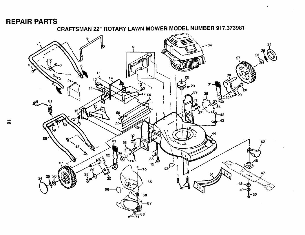
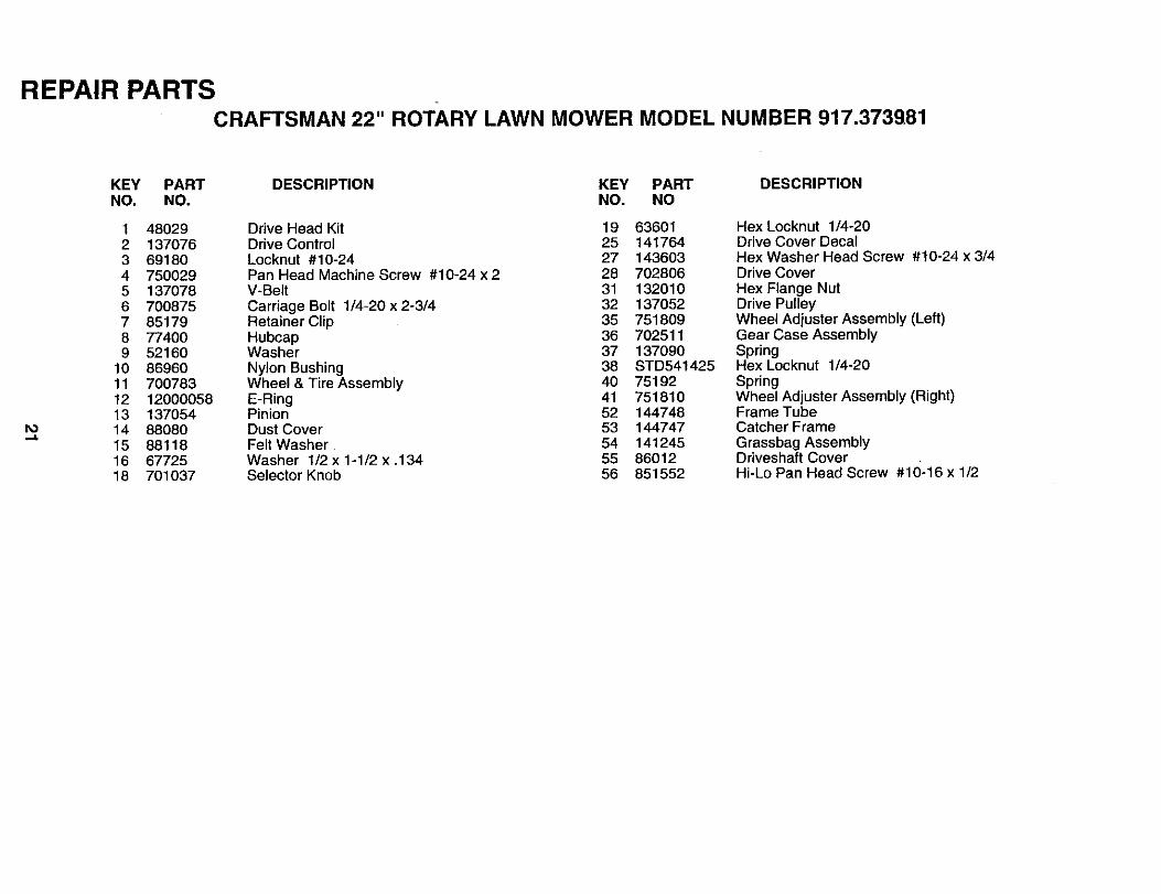
REPAIR PARTSCRAFTSMAN 22" ROTARY LAWN MOWER MODEL NUMBER 917,373981
GO
61I
6\
11
14
56
22
27
3O
24
12
28_ 3 70____ 65
69
67
REPAIR PARTSCRAFTSMAN 22" ROTARY LAWN MOWER MODEL NUMBER 917.373981
.,.I.
{.O
KEY PART DESCRIPTION KEY PART DESCRIPTIONNO. NO NO. NO
1 133088X4792 1308613 743504245 858276 1363767 STD5414258 8515099 48137
11 12841512 STD51250514 700483X47915 700365X47916 133190X47917 140661X47920 14054021 70281322 8554323 8767724 7740025 8517926 5216027 70078128 8492129 6233530 85021X00431 70103732 850855X00434 8492035 133759X00736 133757X00737 5518739 140629X45940 140628X45941 85099842 750097
Upper Handle 43 87930Engine Zone Control Cable 44 48377Hex Head Bolt 1/4-20 x 1-1/2 46 851514Cable Clip 47 141114Handle Knob 48 851074Locknut 1/4-20 49 850263Control Bar 50 851084Rear Door Kit 51 700869X479Pop Rivets 52 85463Hex Tapping Screw 1/4-20 x 1/2 55 751592Back Plate 56 88652Side Baffle 57 51793Discharge Baffle 58 84676X479Rear Baffle 59 131959Rear Skirt 61 103672XMulcher Plug 62 134612Engine Pulley _ 1_L13Z_Hi-Pro Key #505 65 701458Hubcap 66 752240X479Retainer Clip 67 702807Washer 68 141839Wheel & Tire Assembly 69 702808Shoulder Bolt 3/8-16 70 702809Belleville Washer 71 141841Axle Arm Assembly -- 141763Selector Knob - - 144815Selector SpringSpacerWheel Adjusting Bracket (Left)Wheel Adjusting Bracket (Right)Thread Cutting Screw 5/16-18 x 3/4Handle Bracket Assembly (Left)Handle Bracket Assembly (Right)Hex Head Thread Rolling Screw 3/8-16 x 1-1/8Hex Washer Head Screw #10-24 x 1/2
Guide ClipLawn Mower Housing (Incl. Key #14,15,51 &52)Blade AdapterBlade 22"Hardened WasherHelical Washer 3/8-24 x 1-3/8 Grd. 8Hex Head Machine Screw 3/8-24 x 1-3/8 Grd. 8Front BaffleDanger DecalLocknut 3/8-16Hinge ScrewHairpin CotterLower HandleHandle BoltRope GuideDebris ShieldEngine - Craftsman - Model No. 143.945504
o]_55TDoor LatchSide Discharge GuardSpeed NutHinge SpringHinge RodScrewDecalOwner's Manual
Available accessories not included with lawn mower:71 33723 High Wheel Kit71 33623 Gas Can (2.5 gaL)71 33500 Fuel Stabilizer7"133300 SAE 30W Oil (20 oz.)7"133417 Dust Shield7"133316 Mower Cover
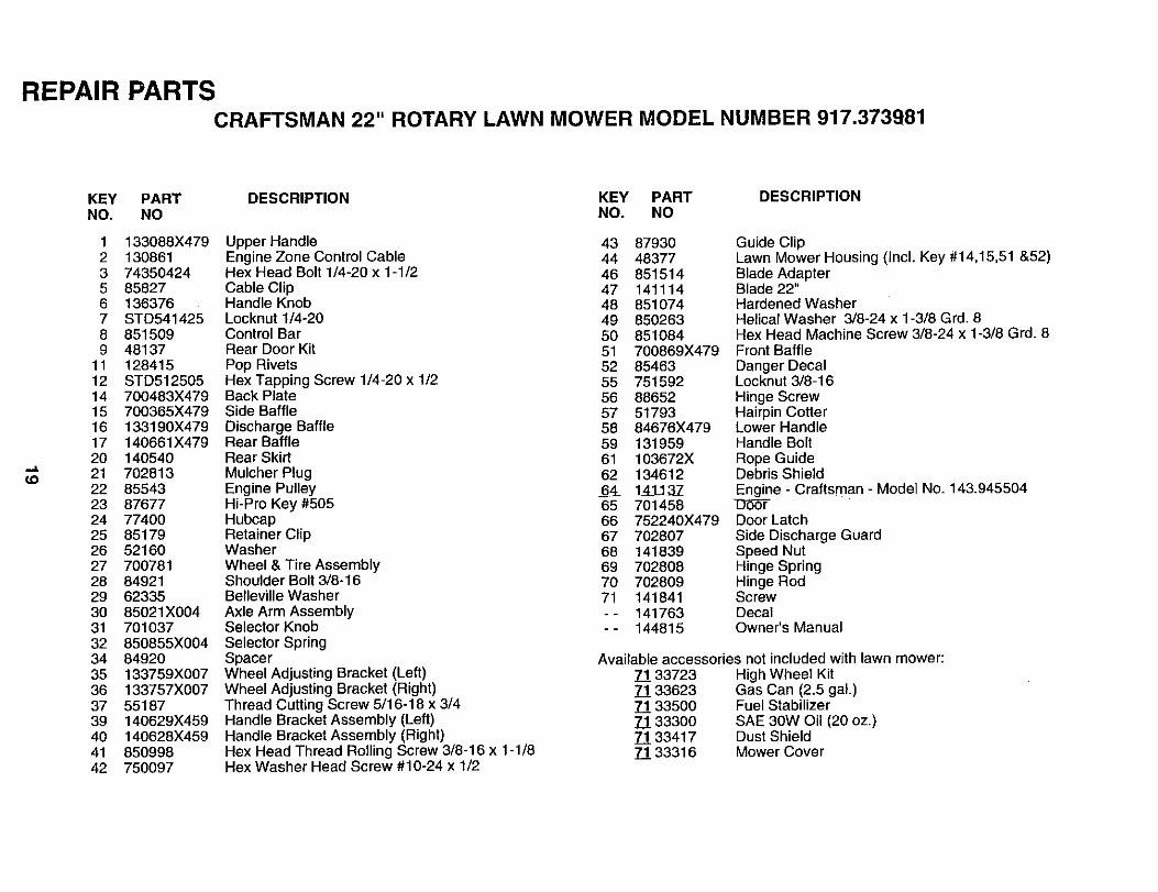
REPAIR PARTSCRAFTSMAN 22" ROTARY LAWN MOWER MODEL NUMBER 917.373981
Ioo
54
18
10
14
41
14 1610
11/ o
|
12
,8
1312
REPAIR PARTSCRAFTSMAN 22" ROTARY LAWN MOWER MODEL NUMBER 917.373981
.,.,,&
KEY PART DESCRIPTION KEY PART DESCRIPTIONNO. NO. NO. NO
1 48029 Drive Head Kit 19 636012 137076 Drive Control 25 1417643 69180 Locknut #10-24 27 1436034 750029 Pan Head Machine Screw #10-24 x 2 28 7028065 137078 V-Belt 31 1320106 700875 Carriage Bolt 1/4-20 x 2-3/4 32 1370527 85179 Retainer Clip 35 7518098 77400 Hubcap 36 7025119 52160 Washer 37 137090
10 86960 Nylon Bushing 38 STD54142511 700783 Wheel & Tire Assembly 40 7519212 12000058 E-Ring 41 75181013 137054 Pinion 52 14474814 88080 Dust Cover 53 14474715 88118 Felt Washer 54 14124516 67725 Washer 1/2 x 1-1/2 x .134 55 8601218 701037 Selector Knob 56 851552
Hex Locknut 1/4-20Drive Cover DecalHex Washer Head Screw #10-24 x 3/4Drive CoverHex Flange NutDrive PulleyWheel Adjuster Assembly (Left)Gear Case AssemblySpringHex Locknut 1/4-20SpringWheel Adjuster Assembly (Right)Frame TubeCatcher FrameGrassbag AssemblyDriveshaft CoverHi-Lo Pan Head Screw #10-16 x 1/2
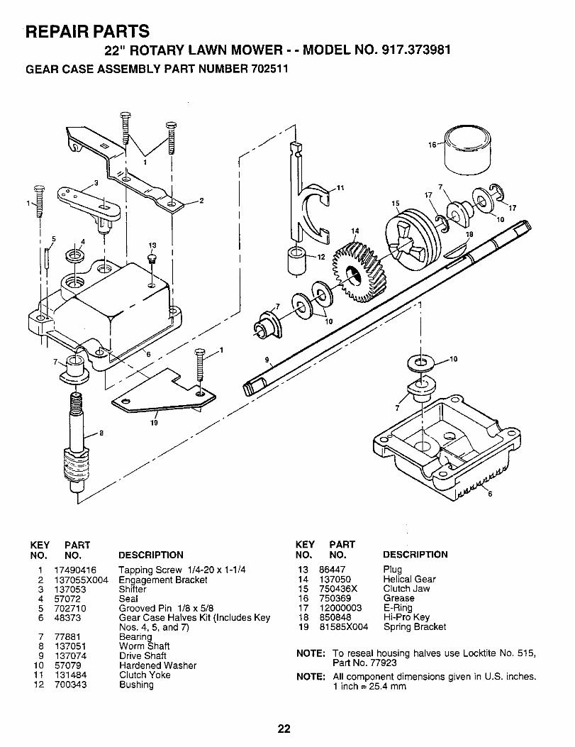
REPAIR PARTS22" ROTARY LAWN MOWER - - MODEL NO. 917.373981
GEAR CASE ASSEMBLY PART NUMBER 702511
13
f
J
J
15
14
17
KEYNO.
123456
789
101t12
PARTNO.
1749O416137055X0041370535707270271048373
7788113705113707457079131484700343
DESCRIPTION
Tapping Screw 1/4-20 x 1-1/4Engagement BracketShifterSealGrooved Pin 1/8 x 5/8Gear Case Halves Kit (Includes KeyNos. 4, 5, and 7)BearingWorm ShaftDrive ShaftHardened WasherClutch YokeBushing
KEY PARTNO. NO. DESCRIP_ON
13 86447 Plug14 137050 Helical Gear15 750436X Clutch Jaw16 750369 Grease17 12000003 E-Ring18 850848 Hi-Pro Key19 81585X004 Spring Bracket
NOTE: To reseal housing halves use Locktite No. 515,Part No. 77923
NOTE: All component dimensions given in U.S. inches.1 inch = 25,4 mm
22
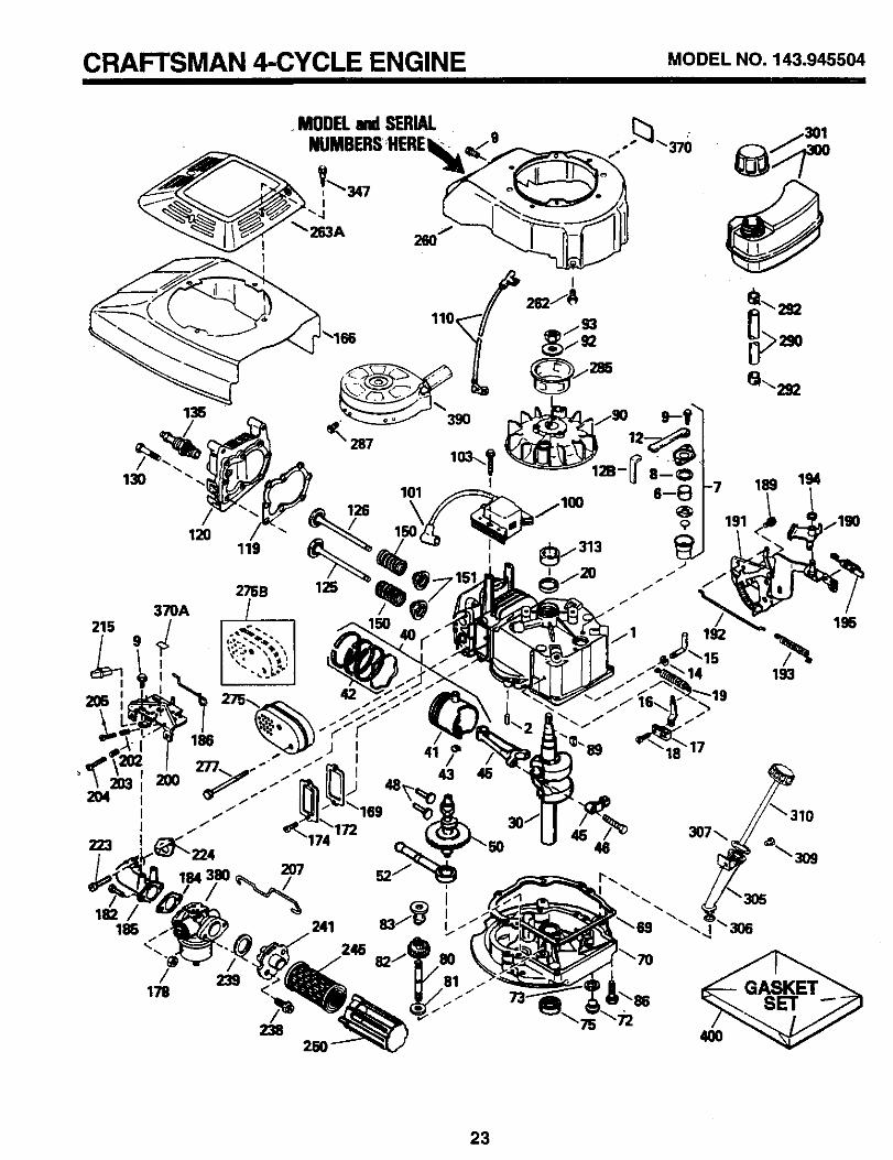
CRAFTSMAN 4-CYCLE ENGINE MODELNO.143.945504
MODELandSERIALNUMBERSHERE
185 / 241
"'/ 239 245 82J_1_1178 /_ _ SET
238 4OO250
23
CRAFTSMAN 4-CYCLE ENGINE MODELNO.143.945504
REF PARTNO. NO.
1 364782 267276 337347 34214A
8 337359 3O2OO
12 3388612B 34695 _14 2827715 3058916 31383A17 3133518 65054819 3628120 3260030 3580140 36073
3607436075
41 360703607136072
42 360763607736078
43 2038145 3287546 32610A48 272415O 3599252 2991469 3526170 34311D72 3057273 2883375 2789780 30574A81 30_90A82 3059183 30588A86 65048889 61100490 61110992 65081593 650816100 34443A101 610118103 650814110 34961119 36477120 36476125 36471
36472126 29314B
29315C
130 6021A135 35395150 35991151 31673166 35827
DESCRIPTIONCylinder (Includes Ref. #2 and 20)Dowel PinBreather ElementBreather Assembly (IncludesReference #6, 8, 9, 12 and 12B)
* Breather GasketScrew #10-24 x 9/16Breather TubeBreather Tube ElbowWasherGovernor Rod (Includes Ref. #14)Governor LeverGovernor Lever ClampScrew #8-32 x 5/16Extension SpringOil SealCrankshaftPiston, Pin & Ring Set, Std. SizePiston, Pin & Ring Set, .010" OverPiston, Pin & Ring Set, .020" OverPiston & Pin Assembly, Std. SizePiston & Pin Assembly, .010" OverPiston & Pin Assembly, .020" Over(Assemblys Include Reference #43)Ring Set, Piston, Standard SizeRing Set, Piston, .010" OversizeRing Set, Piston, .020" OversizePiston Pin Retaining RingConnecting Rod Assy. (IncL #46)Connecting Rod BoltVaive LifterCamshaft (MCR)Oil Pump Assembly
* Mounting Flange GasketMounting Flange (Incl. #72 thru 83)Oil Drain PlugDrain Plug GasketOil SealGovernor ShaftWasherGovernor Gear Assy. (Incl. #81)Governor SpoolScrew 1/4-20 x 1-1/4Flywheel KeyFlywheelBelleviile WasherFlywheel NutSolid State IgnitionSpark Plug CoverScrew, Torx T-15 #10-24 x 1Ground Wire
* Cylinder Head GasketCylinder HeadExhaust Valve, Standard SizeExhaust Valve, 1/32" OversizeIntake Valve, Standard SizeIntake Valve, 1/32" Oversize(Al! Valves Include Reference #151)Screw 5/16-18 x 1-1/2Resistor Spark Plug (RJ19LM)Valve SpringValve Spring CapEngine Shroud
REF PARTNO. NO.169 27234A172 32755174 30200178 29752182 6201184 26756185 31384A186 34337189 650839190 35831191 35039B192 34966193 34965194 32309195 610973200 35727202 36482203 31342204 650549205 650777207 34336215 35511223 650451224 34690A238 650932239 34338241 35797245 35066250 35065260 35826262 850831263A 35821275 36473275B 391020277 650795285 3500O287 65O926290 34357292 26460300 35586301 35355305 35819A306 34265307 35499309 650936310 35822313 34080347 650898370 36261370A 35167380 632681390 690702400 36481
DESCRIPTION* Valve Cover Gasket
Valve CoverScrew #10-24 x 9/16Nut & Lock Washer 1/4-28Screw 1/4-28 x 7/8
* Carburetor To Intake Pipe GasketIntake Pipe (Includes Ref. #224)Governor LinkScrew 1/4-20 x 3/8Brake LeverS.E. Brake Bracket (Includes #195)Brake Control LinkBrake SpringRetaining RingTerminalControl Bracket (Incl. #202-205)Compression SpringCompression SpringScrew #5-40 x 7/16Screw #6-32 x 21/32Throttle LinkControl KnobScrew 1/4-20 x 1
* Intake Pipe GasketScrew #10-32 x 49/64
* Air Cleaner GasketAir Cleaner CollarAir Cleaner FilterAir Cleaner CoverBlower HousingScrew #1/4-20 x 1/2Starter GrillMuffler (Includes Reference #277)Spark Arrestor Muffler (Optional)Screw 1/4-20 x 2-1/4Starter CupScrew #8-32 x 21/64Fuel LineFuel Line ClampFuel Tank (Includes #292 and 301)Fuel CapOil Fill Tube
* O-RingO-RingScrew #10-32 x 13/32DipstickSpacerScrew #10-32 x 27/32Instruction DecalInstruction DecalCarburetor (includes Ref. #184)Rewind StarterGasket Set (Incl. items marked*)
NOTE: This engine could have been built with starter#590637. Refer to the design of the air intake louversfor part identification (individual starter parts do notinterchange).
RPM Settings: Low: 2450-2750, High: 2900-3200
NOTE: All component dimensions given in U.S. inches1 inch = 25.4 mm
24
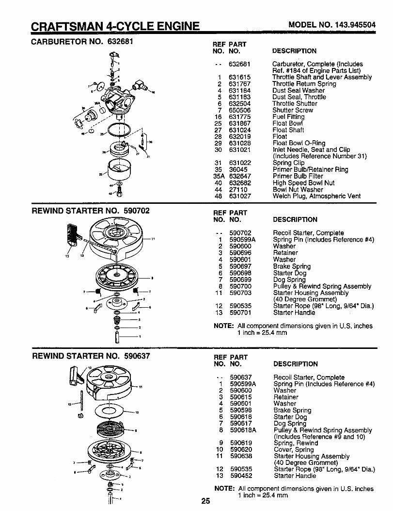
CRAFTSMAN 4-CYCLE ENGINE MODELNO.143.945504CARBURETOR NO. 632681 REF PART
NO. NO.
-- 632681
1 6316152 6317674 6311845 6311836 6325047 650506
16 63177525 63186727 63102428 63201929 63102830 631021
31 63102235 36045
35A 63264740 63268244 2711048 631027
DESCRIPTION
Carburetor, Complete (IncludesRef. #184 of Engine Parts List)Throttle Shaft and Lever AssemblyThrottle Retum SpringDust Seal WasherDust Seal, ThrottleThrottle ShutterShutter ScrewFuel FittingFloat Bow!Float ShaftFloatFloat Bowl O-RingInlet Needle, Seat and Clip(Includes Reference Number 31)Spring ClipPrimer Bulb/Retainer RingPrimer Bulb FilterHigh Speed Bowl NutBowl Nut WasherWelch Plug, Atmospheric Vent
REWIND STARTER NO. 590702 REF PARTNO. NO. DESCRIPTION
-- 5907021 590599A2 5906003 5906964 5906015 5906976 5906987 5906998 590700
11 590703
12 59053513 590701
Recoil Starter, CompleteSpring Pin (Includes Reference #4)WasherRetainerWasherBrake SpringStarter DogDog SpringPulley & Rewind Spring AssemblyStarter Housing Assembly(40 Degree Grommet)Starter Rope (98" Long, 9/64" Dia.)Starter Handle
NOTE: All component dimensions given in U.S. inches1 inch = 25.4 mm
REWIND STARTER NO. 590637 REF PARTNO. NO. DESCRIPTION
-- 5906371 590899A2 5906003 5906154 5906015 5905986 5906167 5906178 590618A
9 59061910 59062011 590638
12 59053513 590452
Recoil Starter, CompleteSpring Pin (Includes Reference #4)WasherRetainerWasherBrake SpringStarter DogDog SpdngPulley & Rewind Spring Assembly_ncludes Reference #9 and 10)
pring, RewindCover, SpringStarter Housing Assembly(40 Degree Grommet)Starter Rope (98" Long, 9/64" Dia.)Starter Handle
NOTE: All component dimensions given in U.S. inches1 inch = 25.4 mm
25
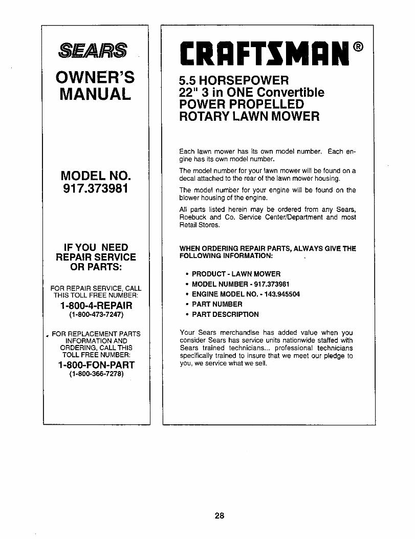
SF_/A/ SOWNER'SMANUAL
MODEL NO.917.373981
IF YOU NEEDREPAIR SERVICE
OR PARTS:
FOR REPAIR SERVICE, CALLTHIS TOLL FREE NUMBER:
1-800-4-REPAIR(1-800-473-7247)
FOR REPLACEMENT PARTSINFORMATION AND
ORDERING, CALL THISTOLL FREE NUMBER:
1-800-FON-PART(1-800-366-7278)
(RrlFTXMRN®5.5 HORSEPOWER22" 3 in ONE ConvertiblePOWER PROPELLEDROTARY LAWN MOWER
Each lawn mower has its own model number. Each en-gine has its own model number.
The model number for your lawn mower will be found on adecal attached to the rear of the lawn mower housing.
The model number for your engine will be found on theblower housing of the engine.
All parts listed herein may be ordered from any Sears,Roebuck and Co. Service Center/Department and mostRetail Stores.
WHEN ORDERING REPAIR PARTS, ALWAYS GIVE THEFOLLOWING INFORMATION:
• PRODUCT- LAWN MOWER
• MODEL NUMBER - 917.373981
• ENGINE MODEL NO. - 143.945504
• PART NUMBER
• PART DESCRIPTION
Your Sears merchandise has added value when youconsider Sears has service units nationwide staffed withSears trained technicians.., professional techniciansspecifically trained to insure that we meet our pledge toyou, we service what we sell.
28


![Dismantling iClass and iClass Eliteflaviog/publications/dismantling.iClass.pdfiClass is an ISO/IEC 15693 [20] compatible contactless smart card manufac-tured by HID Global. It was](https://img.pdfslide.us/doc/110x75/5f3f0bedd8d8cf690f4aac01/dismantling-iclass-and-iclass-flaviogpublicationsdismantlingiclasspdf-iclass.jpg)