Embed Size (px)
Citation preview
USASERVICE OFFICEDometic Corporation2320 Industrial ParkwayElkhart, IN 46516574-294-2511
CANADADometic Corporation46 Zatonski, Unit 3Brantford, ON N3T 5L8CANADA519-720-9578
For Service CenterAssistance Call:800-544-4881
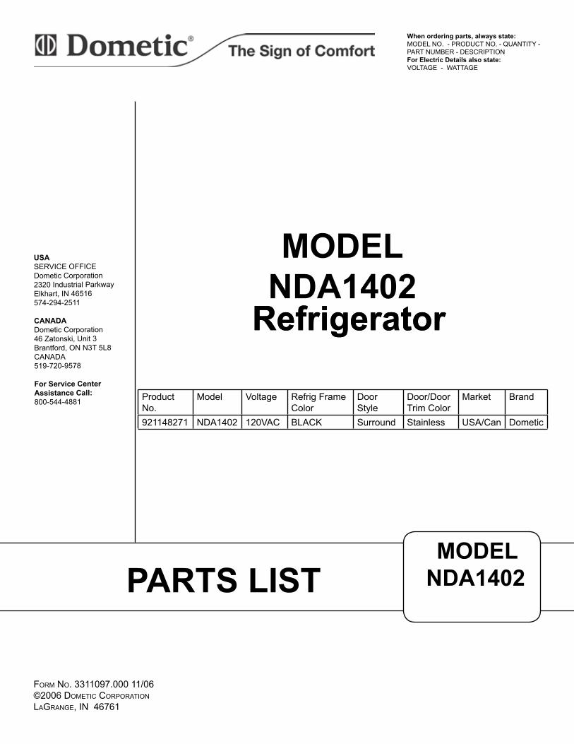
When ordering parts, always state:MODEL NO. - PRODUCT NO. - QUANTITY - PART NUMBER - DESCRIPTIONFor Electric Details also state:VOLTAGE - WATTAGE
MODELNDA1402
Refrigerator
PARTS LISTMODEL
NDA1402
FORM NO. 3311097.000 11/06 ©2006 DOMETIC CORPORATION LAGRANGE, IN 46761
Refrigerator
Product No.
Model Voltage Refrig Frame Color
Door Style
Door/Door Trim Color
Market Brand
921148271 NDA1402 120VAC BLACK Surround Stainless USA/Can Dometic
NDA1402 PARTS LIST
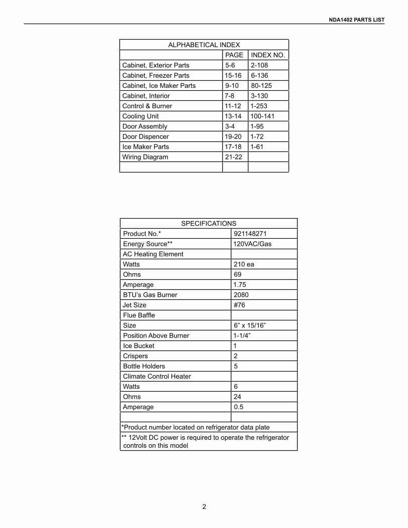
SPECIFICATIONSProduct No.* 921148271Energy Source** 120VAC/GasAC Heating ElementWatts 210 eaOhms 69Amperage 1.75BTU’s Gas Burner 2080Jet Size #76Flue BaffleSize 6” x 15/16”Position Above Burner 1-1/4”Ice Bucket 1Crispers 2Bottle Holders 5Climate Control HeaterWatts 6Ohms 24Amperage 0.5
*Product number located on refrigerator data plate** 12Volt DC power is required to operate the refrigerator controls on this model
ALPHABETICAL INDEXPAGE INDEX NO.
Cabinet, Exterior Parts 5-6 2-108Cabinet, Freezer Parts 15-16 6-136Cabinet, Ice Maker Parts 9-10 80-125Cabinet, Interior 7-8 3-130Control & Burner 11-12 1-253Cooling Unit 13-14 100-141Door Assembly 3-4 1-95Door Dispencer 19-20 1-72Ice Maker Parts 17-18 1-61Wiring Diagram 21-22
2
NDA1402 PARTS LIST
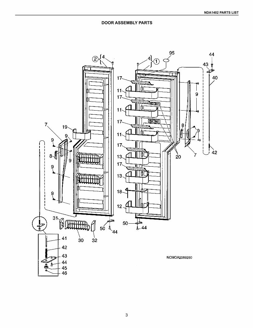
DOOR ASSEMBLY PARTS
3
NDA1402 PARTS LIST
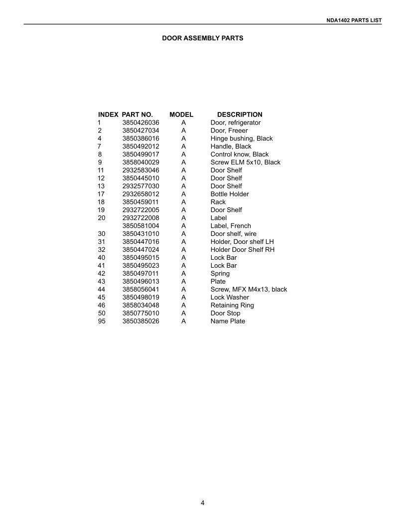
DOOR ASSEMBLY PARTS
INDEX PART NO. MODEL DESCRIPTION1 3850426036 A Door, refrigerator2 3850427034 A Door, Freeer4 3850386016 A Hinge bushing, Black7 3850492012 A Handle, Black8 3850499017 A Control know, Black9 3858040029 A Screw ELM 5x10, Black11 2932583046 A Door Shelf12 3850445010 A Door Shelf13 2932577030 A Door Shelf17 2932658012 A Bottle Holder18 3850459011 A Rack19 2932722005 A Door Shelf 20 2932722008 A Label 3850581004 A Label, French30 3850431010 A Door shelf, wire31 3850447016 A Holder, Door shelf LH32 3850447024 A Holder Door Shelf RH40 3850495015 A Lock Bar41 3850495023 A Lock Bar42 3850497011 A Spring 43 3850496013 A Plate44 3858056041 A Screw, MFX M4x13, black45 3850498019 A Lock Washer46 3858034048 A Retaining Ring50 3850775010 A Door Stop95 3850385026 A Name Plate
4
NDA1402 PARTS LIST
CABINET EXTERIOR PARTS
5
NDA1402 PARTS LIST
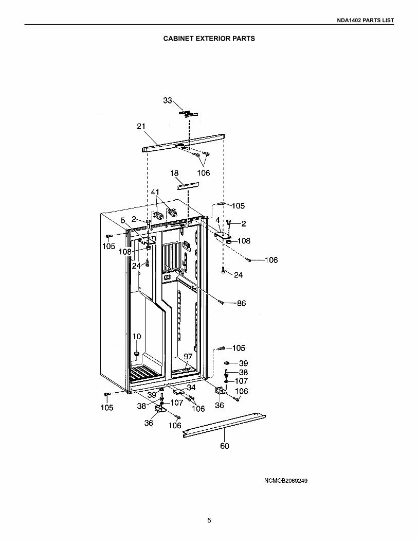
CABINET EXTERIOR PARTS
INDEX PART NO. MODEL DESCRIPTION2 3850400015 A Hinge Pin, Upper4 3850398011 A Hinge, Upper, Black5 3850398026 A Hinge, Upper, Black10 2931715011 A Lid 18 3850682018 A Panel Display Board, Black21 3850460019 A Front Black 24 3858006012 A Scrrew PH4x1033 3850461017 A Holder, Lock, Upper34 3850462015 A Holder, Lock, Lower36 3850397013 A Hinge, Lower Black38 3850399019 A Hinge Pin, Lower39 3858010022 A Washer, Black41 3850456017 A Switch60 2932664093 A Base Cover, Black86 3858004108 A Screw, MRX 5x2595 3851128011 A Spacer, Plastic, Black97 3850693007 A Label105 3858004041 A Screw, MRX 4x6 FZ106 3858039104 A Screw, MRX-TT M4x10 Black107 3858010113 A Washer, BRB 6.4x12.5108 3858009057 A Nut, ML6 M6, Black
6
NDA1402 PARTS LIST
CABINET INTERIOR PARTS
7
NDA1402 PARTS LIST
CABINET INTERIOR PARTS
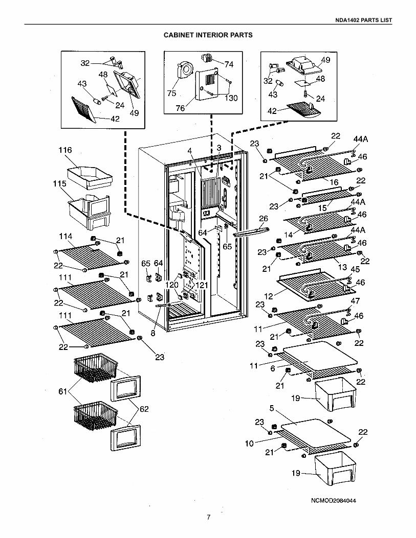
INDEX PART NO. MODEL DESCRIPTION3 3850473020 A Cooling Fins RH4 3850473038 A Cooling Fins LH5 2931117192 A Shelf, Plastic6 2931117184 A Shelf, Plastic8 2931714022 A Outlet10 3850435011 A Shelf11 3850436019 A Shelf12 3850437017 A Shelf 13 3850438015 A Shelf 14 3850440011 A Shelf15 3850439013 A Shelf16 3850441019 A Shelf19 3850442017 A Crisper 21 2932102011 A Shelf Support22 2932101013 A Plug23 2932103019 A Plug24 3858006012 A Screw PH4x1026 3850449012 A Drip tray32 2932108018 A Contact Pin42 3850962014 A Lamp Glass43 2007290006 A Lamp, 10W 12VDC44A 2007337153 A Rack45 2007337237 A Rack46 2930693045 A Holder47 2007337245 A Rack48 3850963012 A Reflector49 3850961016 A Lamp Housing 61 3850430012 A Basket, Wire62 3850444013 A Front, Wire, Basket64 3850484019 A Holder, Outer65 3850485016 A Holder, Inner74 3858062023 A Terminal Black75 3850486014 A Fan76 3850448014 A Cover, Fan111 3850433016 A Shelf114 3850726013 A Shelf115 3850752019 A Ice Box116 3850655014 A Box120 2007393024 A Stop Outside121 2007392026 A Stop, Inside130 3858039013 A Screw, MRX-TT/SW 4x8
8
NDA1402 PARTS LIST
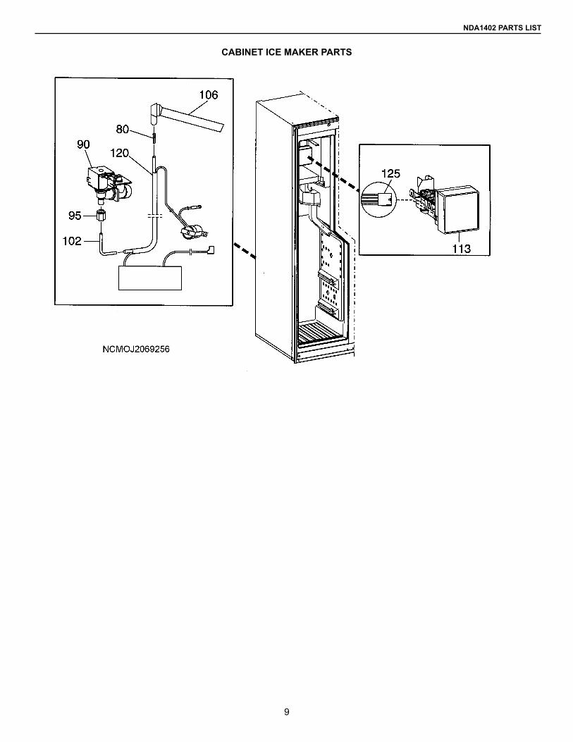
CABINET ICE MAKER PARTS
9
NDA1402 PARTS LISTNDA1402 PARTS LIST
CABINET ICE MAKER PARTS
INDEX PART NO. MODEL DESCRIPTION80 2930841016 A Insert Filler90 3108706.270 A Valve, water95 2930839010 A Nut102 3850220017 A Insert, Copper Water inlet valve106 3105349.009 A Connection113 2932147016 A Ice Maker, Complete120 3850688015 A Kit, Heater water valve125 2954559023 A Harness, wire
10
NDA1402 PARTS LIST
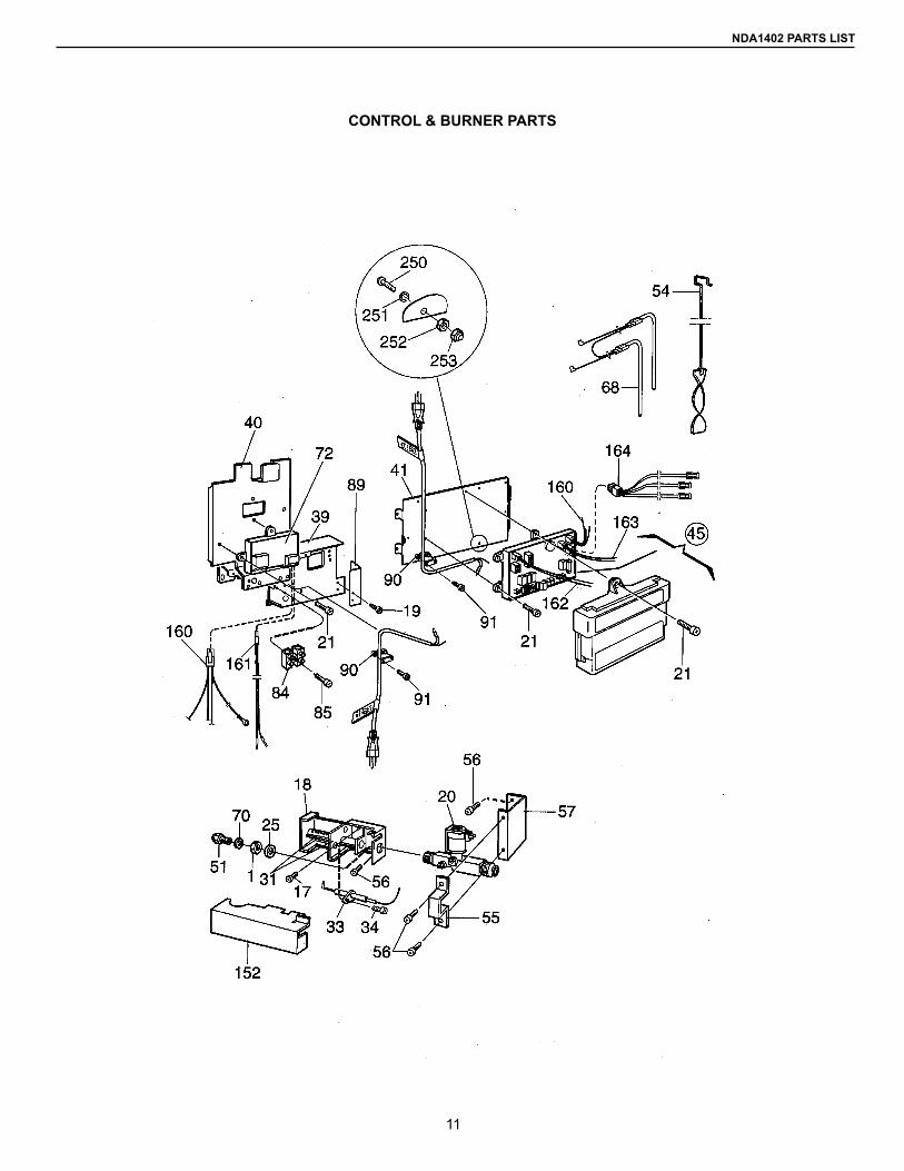
CONTROL & BURNER PARTS
11
NDA1402 PARTS LIST
CONTROL & BURNER PARTS
INDEX PART NO. MODEL DESCRIPTION1 0140207044 A Nut17 3858039039 A Screw, MRX M4x818 2932161017 A Burner Housing19 3858002144 A Screw, RXS B6x920 2932615020 A Solenoid Valve 21 3858002151 A Screw RXS B6x1325 3858010071 A Washer 31 0955001672 A Burner Pipe33 2932781020 A Electrode34 3858002052 A Screw, RXS B6x6.5 39 2932061020 A Bracket40 2932032010 A Holder41 3850710017 A Bracket45 3850681010 A Power Module51 2007419332 A Jet #7654 2932667054 A Flame Spredader55 2932662014 A Bracket56 3858039047 A Screw, MRX M4x1057 2932043017 A Support Plate68 3850644539 A Heater 210W 120VAC70 2007457001 A Washer72 3850708011 A Burner Control84 3858022019 A Terminal Block85 3858002185 A Screw, RXS B6x2589 3850777016 A Bracket, Valve Water91 3858002177 A Cover152 2931401018 A Cover160 2954547028 A Conductor, Burner Control161 2954557019 A Conductor, Solenoid Valve162 3850680012 A Conductor Thermistor, Refr163 3850680020 A Conductor Thermistor Freezer164 2954555013 A Harness250 3858004033 A Screw MRX M4x16251 3858011012 A Lock Washer252 3858009016 A Hex Nut253 3858028024 A Lock Nut
12
NDA1402 PARTS LIST
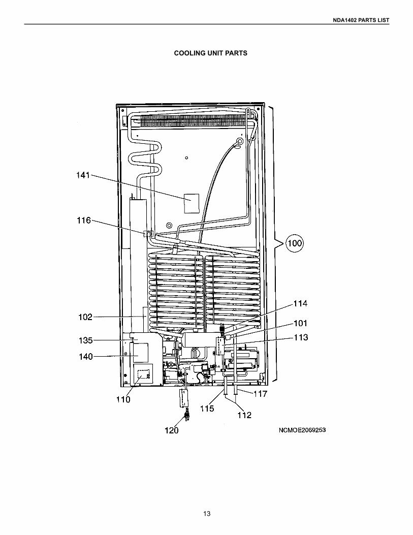
COOLING UNIT PARTS
13
COOLING UNIT PARTS
NDA1402 PARTS LIST
INDEX PART NO. MODEL DESCRIPTION100 2934948106 A Cooling Unit w/fuse, Type 948101 0173228008 A Cap102 2933557023 A Flap110 3850600010 A Blow out protection112 2932115013 A Discharge Pipe Plug113 2932733005 A Label 114 2002699110 A Cord115 2932749035 A Drain Hose116 2932635010 A Drain117 2932749100 A Drain Hose120 2002699177 A Cord135 2932155019 A Support Plate140 3850582002 A Label141 3850583000 A Label
14
NDA1402 PARTS LIST
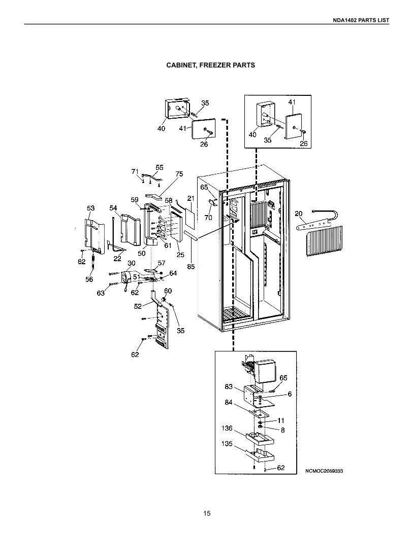
CABINET, FREEZER PARTS
15
INDEX PART NO. MODEL DESCRIPTION6 3858041027 A Screw, M6S 5x25 A2-808 3858009073 A Nut, ML6 M5 11 3858010121 A Washer BRB 6.4x12.5 20 3850674015 A Heating Element, Refrigerator21 3850675012 A Heating Element, Freezer22 3850676010 A Heating Element, Water Drain25 3850629019 A Cooling Fin, Freezer26 3858006046 A Screw, PT 30x1230 3850486022 A Fan, Freezer35 0165521030 A Rivet, Expansion40 3850677018 A Terminal Box, Bottom41 3850678016 A Terminal Box, Cover50 3850648019 A Suction Channel51 3850649017 A Motor Bracket52 3850650015 A Air Distributor53 3850651013 A Cover,W/drip Pan54 3850652011 A Insluation, Cover, Drip Pan55 3850656012 A Support Strip56 3850658018 A Drainage Hose57 3850659016 A Sealing Strip58 3850660014 A Sealing Strip Cooling Fins59 3850661012 A Locking Pin60 3850679014 A Bracket Thermistor61 3858040037 A Screw, EML 5x1262 3858002268 A Screw RXS B8x1963 3858004165 A Screw, MRX M4x4064 3858028032 A Lock Nut, M465 3858004173 A Screw, MRX M4x1070 3850657010 A Support71 3858002235 A Screw, RXS, B6x9.575 3850896014 A Insulation83 3850666011 A Shelf, ice maker84 3850667019 A Plate85 3850734017 A Sealing Strip135 3850668017 A Cover, outer Insulation136 3850669015 A Insulating Plate
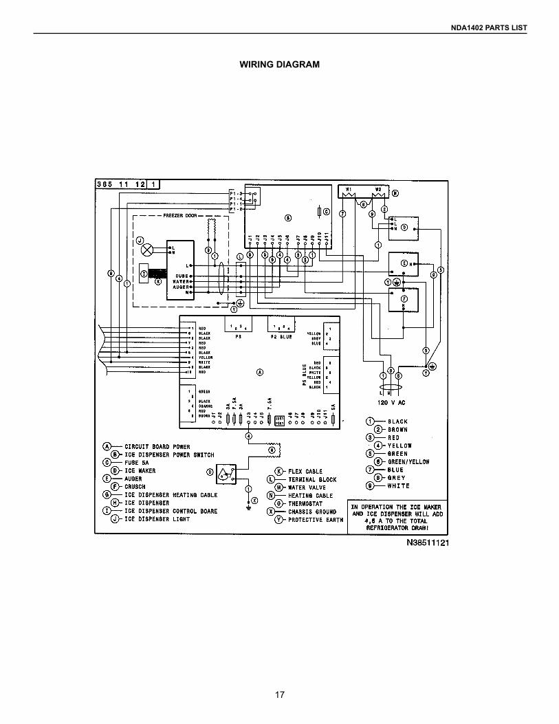
WIRING DIAGRAM
NDA1402 PARTS LIST
17
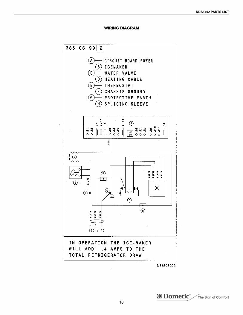
WIRING DIAGRAM
NDA1402 PARTS LIST
18
Form No. 3312186.000 11/07©2007 Dometic CorporationLaGrange, IN. 46761 USA
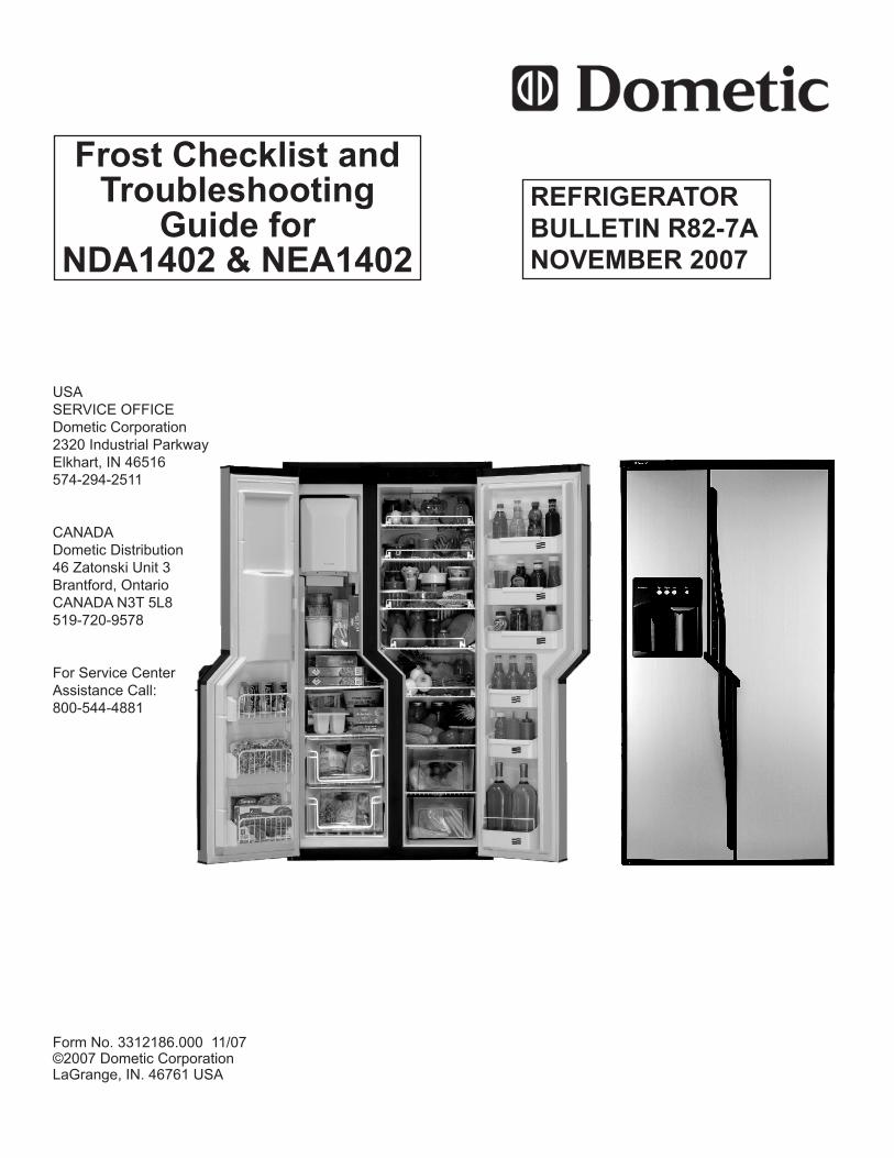
REFRIGERATOR BULLETIN R82-7ANOVEMBER 2007
Frost Checklist andTroubleshooting
Guide forNDA1402 & NEA1402
USASERVICE OFFICEDometic Corporation2320 Industrial ParkwayElkhart, IN 46516574-294-2511
CANADADometic Distribution46 Zatonski Unit 3 Brantford, Ontario CANADA N3T 5L8519-720-9578
For Service CenterAssistance Call:800-544-4881
2
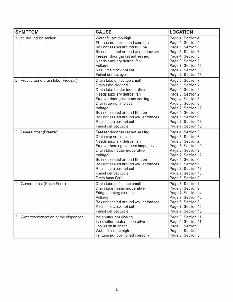
SYMPTOM CAUSE LOCATION1. Ice around Ice maker Water fill set too high
Fill tube not positioned correctlyBox not sealed around fill tube Box not sealed around wall entrancesFreezer door gasket not sealing Needs auxiliary defrost fanVoltageReal time clock not setFailed defrost cycle
Page 4, Section 4Page 5, Section 5Page 5, Section 6Page 5, Section 6Page 4, Section 3Page 3, Section 2Page 7, Section 12Page 7, Section 13Page 7, Section 15
2. Frost around drain tube (Freezer) Drain tube orifice too smallDrain tube cloggedDrain tube heater inoperativeNeeds auxiliary defrost fanFreezer door gasket not sealing Drain cap not in place Voltage Box not sealed around fill tubeBox not sealed around wall entrances Real time clock not set Failed defrost cycle
Page 5, Section 7Page 5, Section 7Page 6, Section 9Page 3, Section 2Page 4, Section 3Page 5, Section 6Page 7, Section 12Page 5, Section 6Page 5, Section 6Page 7, Section 13Page 7, Section 15
3. General frost (Freezer) Freezer door gasket not sealingDrain cap not in placeNeeds auxiliary defrost fanFreezer heating element inoperativeDrain tube heater inoperativeVoltage Box not sealed around fill tubeBox not sealed around wall entrances Real time clock not set Failed defrost cycleDrain hose Split
Page 4, Section 3Page 5, Section 6Page 3, Section 2Page 6, Section 10Page 5, Section 9Page 7, Section 12Page 5, Section 6Page 5, Section 6Page 7, Section 13Page 7, Section 15Page 6, Section 8
4. General frost (Fresh Food) Drain tube orifice too smallDrain tube heater inoperativeFridge heating elementVoltage Box not sealed around wall entrancesReal time clock not setFailed defrost cycle
Page 5, Section 7Page 6, Section 9Page 7, Section 14Page 7, Section 12Page 5, Section 6Page 7, Section 13Page 7, Section 15
5. Water/condensation at the dispenser Ice shutter not closingIce shutter heater inoperativeToo warm in coachWater fill set to high Fill tube not positioned correctly
Page 6, Section 11Page 6, Section 11Page 3, Section 1Page 4, Section 4Page 5, Section 5
3
SAFETY INSTRUCTIONS
This bulletin has safety information and instructions to help users eliminate or reduce the risk of accidents and injuries.
INTRODUCTIONThis Bulletin is applicable for the NDA1402 & NDE1402 model refrigerators. It primarily deals with Frost and Ice issues in the freezer section regarding the auto defrost system.
Make sure the freezer door is sealing properly.• Check if the water supply for the ice maker needs • adjusting.Verify that the ice maker water fill tube is in • place.Check the cabinets wall entrances for wire har-• nesses and fill tube sealing.Make sure the drain plug at the bottom of the • freezer is in place.Inspect the drainage tube to see if it’s blocked or • if the orifice needs to be increased.Check if the drainage heater is looped and mea-• sure the resistance.Verify that the ice shutter is working/sealing prop-• erly.
TOOLS REQUIREDThe refrigerator can be checked with a Phillips screwdriver and a multimeter for checking resistance.
IMPORTANTThe Refrigerator must be completely defrosted before repairs are completed to ensure proper operation.
1. INTERIOR COACH TEMPERATUREIf the interior of the coach is not air conditioned, allowing for higher temperatures and humidity in the inside of the coach, it’s possible to get condensation running out of the dispensing area of the freezer door and onto the floor.
2. AUXILIARY DEFROST FAN KITRefrigerators with serial numbers below 707XXXXX may require an auxiliary fan kit to be installed for proper de-frosting. Contact Technical Service at 800-216-5115 to order an auxiliary fan kit (Part# 385130901). The Refrig-erator must be completely defrosted before repairs are completed to ensure proper operation.
CHECKLISTPerform the following tasks.
4
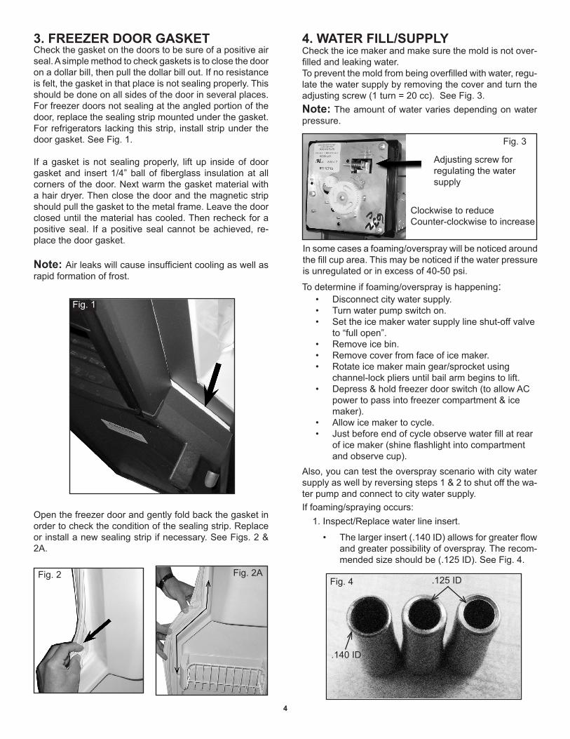
Open the freezer door and gently fold back the gasket in order to check the condition of the sealing strip. Replace or install a new sealing strip if necessary. See Figs. 2 & 2A.
4. WATER FILL/SUPPLY3. FREEZER DOOR GASKETCheck the gasket on the doors to be sure of a positive air seal. A simple method to check gaskets is to close the door on a dollar bill, then pull the dollar bill out. If no resistance is felt, the gasket in that place is not sealing properly. This should be done on all sides of the door in several places. For freezer doors not sealing at the angled portion of the door, replace the sealing strip mounted under the gasket. For refrigerators lacking this strip, install strip under the door gasket. See Fig. 1.
If a gasket is not sealing properly, lift up inside of door gasket and insert 1/4” ball of fiberglass insulation at all corners of the door. Next warm the gasket material with a hair dryer. Then close the door and the magnetic strip should pull the gasket to the metal frame. Leave the door closed until the material has cooled. Then recheck for a positive seal. If a positive seal cannot be achieved, re-place the door gasket.
Note: Air leaks will cause insufficient cooling as well as rapid formation of frost.
Note: The amount of water varies depending on water pressure.
To prevent the mold from being overfilled with water, regu-late the water supply by removing the cover and turn the adjusting screw (1 turn = 20 cc). See Fig. 3.
Check the ice maker and make sure the mold is not over-filled and leaking water.
In some cases a foaming/overspray will be noticed around the fill cup area. This may be noticed if the water pressure is unregulated or in excess of 40-50 psi.
To determine if foaming/overspray is happening:Disconnect city water supply.• Turn water pump switch on.• Set the ice maker water supply line shut-off valve • to “full open”.Remove ice bin.• Remove cover from face of ice maker.• Rotate ice maker main gear/sprocket using • channel-lock pliers until bail arm begins to lift.Depress & hold freezer door switch (to allow AC • power to pass into freezer compartment & ice maker).Allow ice maker to cycle.• Just before end of cycle observe water fill at rear • of ice maker (shine flashlight into compartment and observe cup).
Also, you can test the overspray scenario with city water supply as well by reversing steps 1 & 2 to shut off the wa-ter pump and connect to city water supply.If foaming/spraying occurs:
1. Inspect/Replace water line insert.
Fig. 1
Fig. 2 Fig. 2A
The larger insert (.140 ID) allows for greater flow • and greater possibility of overspray. The recom-mended size should be (.125 ID). See Fig. 4.
Fig. 4
.140 ID
.125 ID
Adjusting screw for regulating the water supply
Fig. 3
Clockwise to reduceCounter-clockwise to increase
5
5. ICE MAKER FILL TUBETo avoid the risk of water leakage outside the inlet, make sure the ice maker fill tube (located behind the ice maker) is inserted far enough in the ice maker water inlet cup. See Fig. 7.
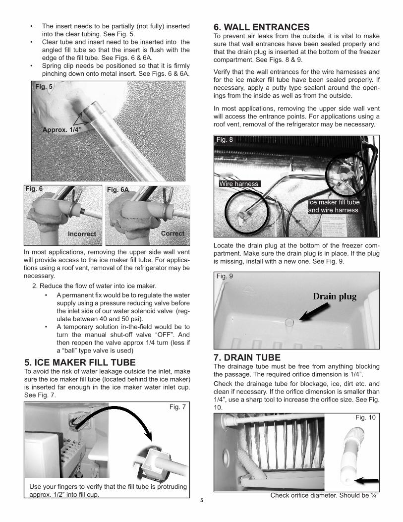
6. WALL ENTRANCESTo prevent air leaks from the outside, it is vital to make sure that wall entrances have been sealed properly and that the drain plug is inserted at the bottom of the freezer compartment. See Figs. 8 & 9.
Verify that the wall entrances for the wire harnesses and for the ice maker fill tube have been sealed properly. If necessary, apply a putty type sealant around the open-ings from the inside as well as from the outside.
Locate the drain plug at the bottom of the freezer com-partment. Make sure the drain plug is in place. If the plug is missing, install with a new one. See Fig. 9.
In most applications, removing the upper side wall vent will access the entrance points. For applications using a roof vent, removal of the refrigerator may be necessary.
The insert needs to be partially (not fully) inserted • into the clear tubing. See Fig. 5.Clear tube and insert need to be inserted into the • angled fill tube so that the insert is flush with the edge of the fill tube. See Figs. 6 & 6A.Spring clip needs be positioned so that it is firmly • pinching down onto metal insert. See Figs. 6 & 6A.
Approx. 1/4”
Fig. 5
Fig. 6A
Correct
Fig. 6
Incorrect
In most applications, removing the upper side wall vent will provide access to the ice maker fill tube. For applica-tions using a roof vent, removal of the refrigerator may be necessary.
2. Reduce the flow of water into ice maker.A permanent fix would be to regulate the water • supply using a pressure reducing valve before the inlet side of our water solenoid valve (reg-ulate between 40 and 50 psi). A temporary solution in-the-field would be to • turn the manual shut-off valve “OFF”. And then reopen the valve approx 1/4 turn (less if a “ball” type valve is used)
Use your fingers to verify that the fill tube is protruding approx. 1/2” into fill cup.
Fig. 7
Fig. 9
Wire harness
Ice maker fill tube and wire harness
Fig. 8
7. DRAIN TUBEThe drainage tube must be free from anything blocking the passage. The required orifice dimension is 1/4”.Check the drainage tube for blockage, ice, dirt etc. and clean if necessary. If the orifice dimension is smaller than 1/4”, use a sharp tool to increase the orifice size. See Fig. 10.
Check orifice diameter. Should be ¼”
Fig. 10
6
11. ICE SHUTTEREnsure the ice shutter closes properly. Give the shutter a little push and watch it close completely. Verify for debris on the shutter that does not allow for a tight seal. If it is not working as intended, the dispenser mechanism should be disassembled for troubleshooting. See Fig. 13.
10. FREEZER HEATING ELEMENT
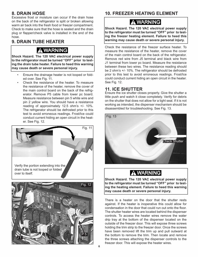
Check the resistance of the freezer surface heater. To measure the resistance of the heater, remove the cover of the main control board on the back of the refrigerator. Remove red wire from J5 terminal and black wire from J1 terminal from lower pc board. Measure the resistance between these two wires. The resistance reading should be 2 ohm’s +/- 10%. The refrigerator should be defrosted prior to this test to avoid erroneous readings. Frost/Ice could conduct current hiding an open circuit in the heater. See Fig. 12.
There is a heater on the door that the shutter rests against. If the heater is inoperative this could allow for condensation in the door that could run out onto the floor. The shutter heater wires are located behind the dispenser controls. To access the heater wires remove the water drip tray at the bottom of the dispenser located on the outside of the freezer door. This will expose three screws holding the trim strip to the freezer door. Once the screws have been removed lift the trim up and pull outward at the bottom to remove the trim. Then locate and remove the three screws attaching the dispenser controls to the freezer door. This will expose the heater wires.
8. DRAIN HOSEExcessive frost or moisture can occur if the drain hose on the back of the refrigerator is split or broken allowing warm air back into the fresh food or freezer compartment. Check to make sure that the hose is sealed and the drain plug or flapper/check valve is installed in the end of the hose.9. DRAIN TUBE HEATER
Ensure the drainage heater is not looped or fold-• ed over. See Fig. 11.Check the resistance of the heater. To measure • the resistance of the heater, remove the cover of the main control board on the back of the refrig-erator. Remove P5 cable from lower pc board. Measure resistance between pin 5 white wire and pin 2 yellow wire. You should have a resistance reading of approximately 12.5 ohm’s +/- 10%. The refrigerator should be defrosted prior to this test to avoid erroneous readings. Frost/Ice could conduct current hiding an open circuit in the heat-er. See Fig. 12.
Shock Hazard. The 120 VAC electrical power supply to the refrigerator must be turned “OFF” prior to test-ing the drain tube heater. Failure to heed this warning may cause death or severe personal injury.
Fig. 11
Verify the portion extending into the drain tube is not looped or folded over to itself.
Check Shutter
Fig. 13
Shock Hazard. The 120 VAC electrical power supply to the refrigerator must be turned “OFF” prior to test-ing the freezer heating element. Failure to heed this warning may cause death or severe personal injury.
Shock Hazard. The 120 VAC electrical power supply to the refrigerator must be turned “OFF” prior to test-ing the heating element. Failure to heed this warning may cause death or severe personal injury.
Fig. 12
J 1J 5
P 5
7
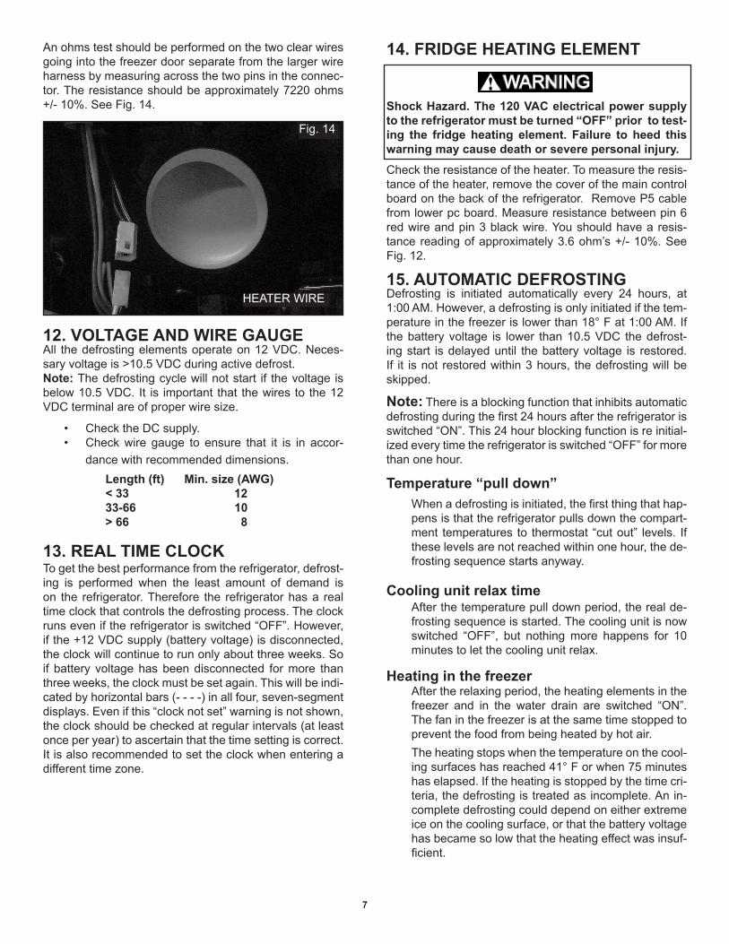
An ohms test should be performed on the two clear wires going into the freezer door separate from the larger wire harness by measuring across the two pins in the connec-tor. The resistance should be approximately 7220 ohms +/- 10%. See Fig. 14.
12. VOLTAGE AND WIRE GAUGEAll the defrosting elements operate on 12 VDC. Neces-sary voltage is >10.5 VDC during active defrost. Note: The defrosting cycle will not start if the voltage is below 10.5 VDC. It is important that the wires to the 12 VDC terminal are of proper wire size.
Check the DC supply. • Check wire gauge to ensure that it is in accor-• dance with recommended dimensions.
Length (ft) Min. size (AWG)< 33 1233-66 10> 66 8
13. REAL TIME CLOCKTo get the best performance from the refrigerator, defrost-ing is performed when the least amount of demand is on the refrigerator. Therefore the refrigerator has a real time clock that controls the defrosting process. The clock runs even if the refrigerator is switched “OFF”. However, if the +12 VDC supply (battery voltage) is disconnected, the clock will continue to run only about three weeks. So if battery voltage has been disconnected for more than three weeks, the clock must be set again. This will be indi-cated by horizontal bars (- - - -) in all four, seven-segment displays. Even if this “clock not set” warning is not shown, the clock should be checked at regular intervals (at least once per year) to ascertain that the time setting is correct. It is also recommended to set the clock when entering a different time zone.
14. FRIDGE HEATING ELEMENT
Check the resistance of the heater. To measure the resis-tance of the heater, remove the cover of the main control board on the back of the refrigerator. Remove P5 cable from lower pc board. Measure resistance between pin 6 red wire and pin 3 black wire. You should have a resis-tance reading of approximately 3.6 ohm’s +/- 10%. See Fig. 12.
HEATER WIRE
Fig. 14
15. AUTOMATIC DEFROSTINGDefrosting is initiated automatically every 24 hours, at 1:00 AM. However, a defrosting is only initiated if the tem-perature in the freezer is lower than 18° F at 1:00 AM. If the battery voltage is lower than 10.5 VDC the defrost-ing start is delayed until the battery voltage is restored. If it is not restored within 3 hours, the defrosting will be skipped.
Note: There is a blocking function that inhibits automatic defrosting during the first 24 hours after the refrigerator is switched “ON”. This 24 hour blocking function is re initial-ized every time the refrigerator is switched “OFF” for more than one hour.
Temperature “pull down”When a defrosting is initiated, the first thing that hap-pens is that the refrigerator pulls down the compart-ment temperatures to thermostat “cut out” levels. If these levels are not reached within one hour, the de-frosting sequence starts anyway.
Cooling unit relax timeAfter the temperature pull down period, the real de-frosting sequence is started. The cooling unit is now switched “OFF”, but nothing more happens for 10 minutes to let the cooling unit relax.
Heating in the freezerAfter the relaxing period, the heating elements in the freezer and in the water drain are switched “ON”. The fan in the freezer is at the same time stopped to prevent the food from being heated by hot air.The heating stops when the temperature on the cool-ing surfaces has reached 41° F or when 75 minutes has elapsed. If the heating is stopped by the time cri-teria, the defrosting is treated as incomplete. An in-complete defrosting could depend on either extreme ice on the cooling surface, or that the battery voltage has became so low that the heating effect was insuf-ficient.
Shock Hazard. The 120 VAC electrical power supply to the refrigerator must be turned “OFF” prior to test-ing the fridge heating element. Failure to heed this warning may cause death or severe personal injury.
8
If 2 incomplete defrostings occur in a row, the warn-ing message “Er 01” is displayed.
Note: The WARNING “Er 01” indicates that 2 or more consecutive defrosting attempts failed. This message will disappear when a defrosting has com-pleted successfully. But it will also be cleared if pow-er is switched “OFF” and then “ON”.
Heating in the fridge
After the defrosting, normal thermostatic operation is restarted again. However, the heating element in the water drain is still “ON” for some time. It is switched “OFF” 30 minutes after the start of the fridge defrost-ing period.
Freezer fan operation during and after a de-frosting
After a defrosting, the fan in the freezer is not started until the temperature on the cooling surfaces be-comes colder than the air temperature in the freez-er.
Note: The warning “Er 02” indicates that the fan in the freezer is blocked (by ice probably). As soon as the fan can move again, this message disappears. The fan has to be blocked for at least one hour be-fore this message is shown. When the fan is “OK” it will only be a delay of about one minute before the message is cleared.
Power breaks during a defrostingIf the +12 VDC is removed for short periods of time or if the refrigerator is switched “OFF” and then “ON” again during a automatic defrost, the defrosting will continue from the point where it was interrupted. However, if power has been “OFF” for more than one hour, the remaining part of the defrost is skipped.
Cancelling of an automatically initiated de-frosting
If, for some reason an automatically initiated defrost-ing needs to be cancelled. Enter the “Service mode”. Then switch the refrigerator “OFF” and then “ON” again. This cancelling will not work immediately after the defrosting is initiated a 1:00 AM. Wait at least three minutes before trying to cancel the defrosting.
17. MANUAL DEFROSTINGA manually initiated defrosting will start if the “AUTO/STORE” button is held down during “power up”. However, if the freezer door is open during this initiation, a drying up period is instead started. (See below). A manually initiated defrosting is identical to an automatically initiated defrost-ing with the exception that the defrosting sequence starts immediately with the “relaxing period”, that is without any initial temperature “pull down” period. A manually initiated defrosting may be cancelled at any time just by switch-ing the refrigerator “OFF” and then “ON” by means of the “ON/OFF” button. However, a short 12 VDC power break will not cancel the defrosting.
18. DRYING FUNCTIONWhen the refrigerator is to be off for some time, the com-partments must have a chance to dry up to prevent mold from forming. The doors should then be left open. Howev-er, the cooling surfaces in the freezer will dry very slowly as they are well encapsulated and the air convection is small. Therefore the refrigerator has a feature that can speed up the drying up of the freezer. To initiate this dry-ing function, start the refrigerator with the “AUTO/STORE” button held down and the freezer door open. If required, the drying function starts with a defrosting. The drying period will take about 3 hours (longer if a defrosting is first performed). Afterwards the refrigerator is automati-cally switched off. The drying function may be terminated by switching off the refrigerator or by closing the freezer door.
16. ENTERING THE SERVICE MODEBefore entering the “Service mode”, switch “OFF” the refrigerator with the “ON/OFF” button. To enter the ser-vice mode, press and hold the “SET” button then press “ON/OFF” button to the “ON” position. In this mode the refrigerator is not operating normally. Instead a number of tests can be performed and the “SET” button is used to step through the tests. The test number and the result of the test are displayed alternating (flashed). Stepping be-yond the last test will result in a restart from test number 1 again. The refrigerator will automatically exit the “Service mode” if no action is detected for 3 minutes. To manu-ally exit, switch the refrigerator “OFF” and then back “ON” again.
The heating is also stopped before the defrosting is completed if the battery voltage drops below the bat-tery protection level.
After the defrosting of the freezer, the cooling unit is restarted again. It takes some time before cold is produced and during that period, the defrosting in the fridge now takes place. After a one minute delay, the heating element in the fridge is switched “ON”. The fan in the fridge is stopped during this defrost-ing cycle. The heating element in the water drain line remains “ON”. The defrosting in the fridge is terminated when the temperature on the cooling surfaces has reached 41° F or when 20 minutes has elapsed.
The fan in the freezer is stopped during defrosting in the freezer, but it is started for short periods at cer-tain intervals for testing and to prevent it from being blocked. A permanently blocked fan will result in the error code “Er 02”.This error message is also shown if the fan is permanently blocked during normal ther-mostatic operation.
9
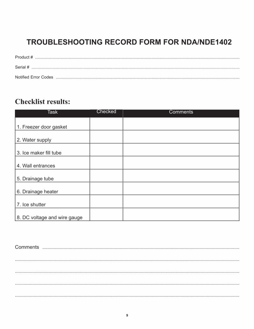
TROUBLESHOOTING RECORD FORM FOR NDA/NDE1402
Product # ................................................................................................................................................................................. Serial # ....................................................................................................................................................................................
Notified Error Codes ...............................................................................................................................................................
Checklist results:
Comments ..............................................................................................................................................................
....................................................................................................................................................................................
....................................................................................................................................................................................
....................................................................................................................................................................................
....................................................................................................................................................................................
1. Freezer door gasket
2. Water supply
3. Ice maker fill tube
4. Wall entrances
5. Drainage tube
6. Drainage heater
7. Ice shutter
8. DC voltage and wire gauge
Task CommentsChecked