Embed Size (px)
Citation preview
SH (NA) 030128-E (1504) MEE Printed in Japan Specifications are subject to change without notice. This Instruction Manual uses recycled paper.
MODEL
MODELCODE
General-Purpose AC Servo
MR
-JE-_A
SE
RV
O A
MP
LIF
IER
INS
TR
UC
TIO
N M
AN
UA
L
HEAD OFFICE : TOKYO BLDG MARUNOUCHI TOKYO 100-8310
MODEL
MR-JE-_ASERVO AMPLIFIER INSTRUCTION MANUAL
General-Purpose Interface AC Servo
1CW706
MR-JE-A SERVOAMPLIFIER INSTRUCTIONMANUAL
E
E
A - 1
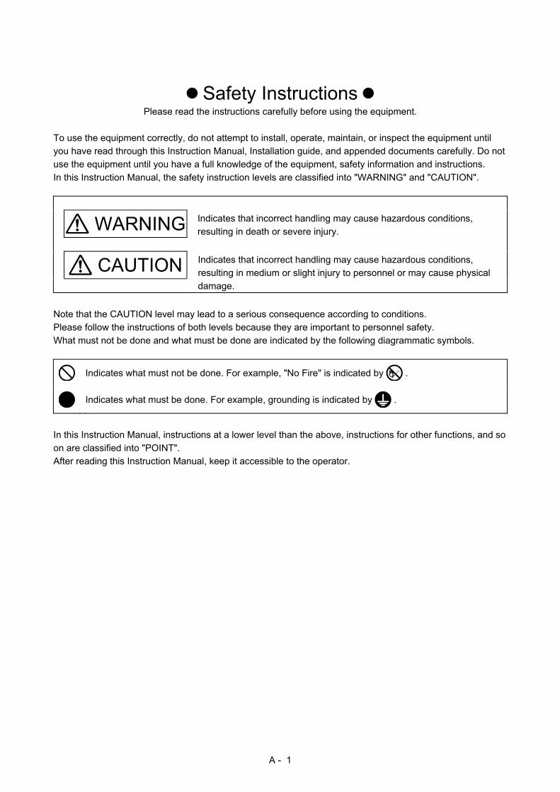
Safety Instructions Please read the instructions carefully before using the equipment.
To use the equipment correctly, do not attempt to install, operate, maintain, or inspect the equipment until
you have read through this Instruction Manual, Installation guide, and appended documents carefully. Do not
use the equipment until you have a full knowledge of the equipment, safety information and instructions.
In this Instruction Manual, the safety instruction levels are classified into "WARNING" and "CAUTION".
WARNING Indicates that incorrect handling may cause hazardous conditions,
resulting in death or severe injury.
CAUTION Indicates that incorrect handling may cause hazardous conditions,
resulting in medium or slight injury to personnel or may cause physical
damage.
Note that the CAUTION level may lead to a serious consequence according to conditions.
Please follow the instructions of both levels because they are important to personnel safety.
What must not be done and what must be done are indicated by the following diagrammatic symbols.
Indicates what must not be done. For example, "No Fire" is indicated by .
Indicates what must be done. For example, grounding is indicated by .
In this Instruction Manual, instructions at a lower level than the above, instructions for other functions, and so
on are classified into "POINT".
After reading this Instruction Manual, keep it accessible to the operator.
A - 2
1. To prevent electric shock, note the following
WARNING Before wiring and inspections, turn off the power and wait for 15 minutes or more until the charge lamp turns off. Otherwise, an electric shock may occur. In addition, when confirming whether the charge lamp is off or not, always confirm it from the front of the servo amplifier. Ground the servo amplifier and servo motor securely. Any person who is involved in wiring and inspection should be fully competent to do the work. Do not attempt to wire the servo amplifier and servo motor until they have been installed. Otherwise, it may cause an electric shock. Do not operate switches with wet hands. Otherwise, it may cause an electric shock. The cables should not be damaged, stressed, loaded, or pinched. Otherwise, it may cause an electric shock. To prevent an electric shock, always connect the protective earth (PE) terminal (marked ) of the servo amplifier to the protective earth (PE) of the cabinet. To avoid an electric shock, insulate the connections of the power supply terminals.
2. To prevent fire, note the following
CAUTION Install the servo amplifier, servo motor, and regenerative resistor on incombustible material. Installing them directly or close to combustibles will lead to smoke or a fire. Always connect a magnetic contactor between the power supply and the power supply (L1, L2, and L3) of the servo amplifier, in order to configure a circuit that shuts down the power supply on the side of the servo amplifier’s power supply. If a magnetic contactor is not connected, continuous flow of a large current may cause smoke or a fire when the servo amplifier malfunctions. Always connect a molded-case circuit breaker, or a fuse to each servo amplifier between the power supply and the main circuit power supply (L1, L2, and L3) of the servo amplifier, in order to configure a circuit that shuts down the power supply on the side of the servo amplifier’s power supply. If a molded-case circuit breaker or fuse is not connected, continuous flow of a large current may cause smoke or a fire when the servo amplifier malfunctions. When using the regenerative resistor, switch power off with the alarm signal. Otherwise, a regenerative transistor malfunction or the like may overheat the regenerative resistor, causing smoke or a fire. When you use a regenerative option with an MR-JE-40A to MR-JE-100A, remove the built-in regenerative resistor and wiring from the servo amplifier. Provide adequate protection to prevent screws and other conductive matter, oil and other combustible matter from entering the servo amplifier and servo motor.
3. To prevent injury, note the following
CAUTION Only the voltage specified in the Instruction Manual should be applied to each terminal. Otherwise, a burst, damage, etc. may occur. Connect cables to the correct terminals. Otherwise, a burst, damage, etc. may occur. Ensure that polarity (+/-) is correct. Otherwise, a burst, damage, etc. may occur. The servo amplifier heat sink, regenerative resistor, servo motor, etc. may be hot while power is on or for some time after power-off. Take safety measures, e.g. provide covers, to avoid accidentally touching the parts (cables, etc.) by hand.
A - 3
4. Additional instructions The following instructions should also be fully noted. Incorrect handling may cause a malfunction, injury,
electric shock, fire, etc.
(1) Transportation and installation
CAUTION Transport the products correctly according to their mass.
Stacking in excess of the specified number of product packages is not allowed.
Do not hold the lead wire of the regenerative resistor when transporting the servo amplifier.
Install the servo amplifier and the servo motor in a load-bearing place in accordance with the Instruction
Manual.
Do not get on or put heavy load on the equipment.
The equipment must be installed in the specified direction.
Leave specified clearances between the servo amplifier and the cabinet walls or other equipment.
Do not install or operate the servo amplifier and servo motor which have been damaged or have any
parts missing.
Do not block the intake and exhaust areas of the servo amplifier. Otherwise, it may cause a malfunction.
Do not drop or strike the servo amplifier and servo motor. Isolate them from all impact loads.
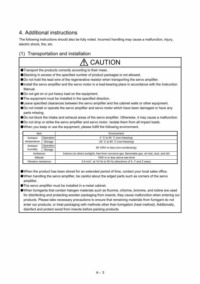
When you keep or use the equipment, please fulfill the following environment.
Item Environment
Ambient temperature
Operation 0 ˚C to 55 ˚C (non-freezing)
Storage -20 ˚C to 65 ˚C (non-freezing)
Ambient humidity
Operation 90 %RH or less (non-condensing)
Storage
Ambience Indoors (no direct sunlight), free from corrosive gas, flammable gas, oil mist, dust, and dirt
Altitude 1000 m or less above sea level
Vibration resistance 5.9 m/s2, at 10 Hz to 55 Hz (directions of X, Y and Z axes)
When the product has been stored for an extended period of time, contact your local sales office.
When handling the servo amplifier, be careful about the edged parts such as corners of the servo
amplifier.
The servo amplifier must be installed in a metal cabinet.
When fumigants that contain halogen materials such as fluorine, chlorine, bromine, and iodine are used
for disinfecting and protecting wooden packaging from insects, they cause malfunction when entering our
products. Please take necessary precautions to ensure that remaining materials from fumigant do not
enter our products, or treat packaging with methods other than fumigation (heat method). Additionally,
disinfect and protect wood from insects before packing products.
A - 4
(2) Wiring
CAUTION Before removing the CNP1 connector of MR-JE-40A to MR-JE-100A, disconnect the lead wires of the
regenerative resistor from the CNP1 connector.
Wire the equipment correctly and securely. Otherwise, the servo motor may operate unexpectedly.
Do not install a power capacitor, surge killer, or radio noise filter (optional FR-BIF) on the servo amplifier
output side.
To avoid a malfunction, connect the wires to the correct phase terminals (U, V, and W) of the servo
amplifier and servo motor.
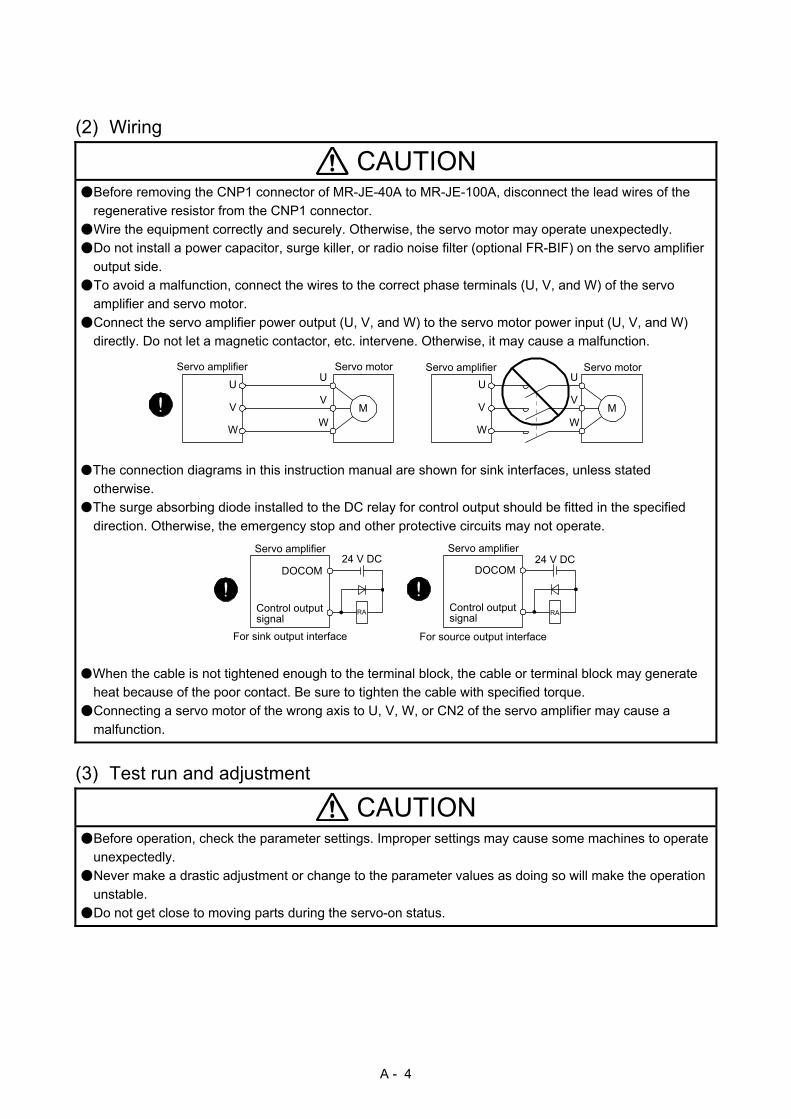
Connect the servo amplifier power output (U, V, and W) to the servo motor power input (U, V, and W)
directly. Do not let a magnetic contactor, etc. intervene. Otherwise, it may cause a malfunction.
U
Servo motor
MV
W
U
V
W
U
MV
W
U
V
W
Servo amplifier Servo motorServo amplifier
The connection diagrams in this instruction manual are shown for sink interfaces, unless stated
otherwise.
The surge absorbing diode installed to the DC relay for control output should be fitted in the specified
direction. Otherwise, the emergency stop and other protective circuits may not operate.
DOCOM
Control outputsignal
Servo amplifier
RA
For sink output interface
24 V DC
DOCOM
Control outputsignal
24 V DCServo amplifier
RA
For source output interface
When the cable is not tightened enough to the terminal block, the cable or terminal block may generate
heat because of the poor contact. Be sure to tighten the cable with specified torque.
Connecting a servo motor of the wrong axis to U, V, W, or CN2 of the servo amplifier may cause a
malfunction.
(3) Test run and adjustment
CAUTION Before operation, check the parameter settings. Improper settings may cause some machines to operate
unexpectedly.
Never make a drastic adjustment or change to the parameter values as doing so will make the operation
unstable.
Do not get close to moving parts during the servo-on status.
A - 5
(4) Usage
CAUTION When it is assumed that a hazardous condition may occur due to a power failure or product malfunction,
use a servo motor with an external brake to prevent the condition.
Do not disassemble, repair, or modify the equipment.
Before resetting an alarm, make sure that the run signal of the servo amplifier is off in order to prevent a
sudden restart. Otherwise, it may cause an accident.
Use a noise filter, etc. to minimize the influence of electromagnetic interference. Electromagnetic
interference may be given to the electronic equipment used near the servo amplifier.
Burning or breaking a servo amplifier may cause a toxic gas. Do not burn or break it.
Use the servo amplifier with the specified servo motor.
The electromagnetic brake on the servo motor is designed to hold the motor shaft and should not be
used for ordinary braking.
For such reasons as service life and mechanical structure (e.g. where a ball screw and the servo motor
are coupled via a timing belt), the electromagnetic brake may not hold the motor shaft. To ensure safety,
install a stopper on the machine side.
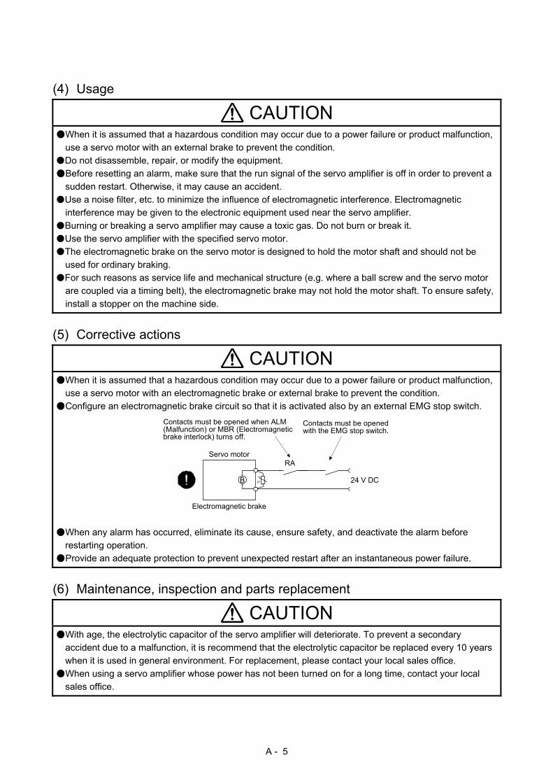
(5) Corrective actions
CAUTION When it is assumed that a hazardous condition may occur due to a power failure or product malfunction,
use a servo motor with an electromagnetic brake or external brake to prevent the condition.
Configure an electromagnetic brake circuit so that it is activated also by an external EMG stop switch.
Servo motor
Electromagnetic brake
B
RA
Contacts must be openedwith the EMG stop switch.
Contacts must be opened when ALM(Malfunction) or MBR (Electromagneticbrake interlock) turns off.
24 V DC
When any alarm has occurred, eliminate its cause, ensure safety, and deactivate the alarm before
restarting operation.
Provide an adequate protection to prevent unexpected restart after an instantaneous power failure.
(6) Maintenance, inspection and parts replacement
CAUTION With age, the electrolytic capacitor of the servo amplifier will deteriorate. To prevent a secondary
accident due to a malfunction, it is recommend that the electrolytic capacitor be replaced every 10 years
when it is used in general environment. For replacement, please contact your local sales office.
When using a servo amplifier whose power has not been turned on for a long time, contact your local
sales office.

A - 6
(7) General instruction To illustrate details, the equipment in the diagrams of this Instruction Manual may have been drawn
without covers and safety guards. When the equipment is operated, the covers and safety guards must
be installed as specified. Operation must be performed in accordance with this Instruction Manual.
DISPOSAL OF WASTE
Please dispose a servo amplifier and other options according to your local laws and regulations.
EEP-ROM life
The number of write times to the EEP-ROM, which stores parameter settings, etc., is limited to 100,000. If
the total number of the following operations exceeds 100,000, the servo amplifier may malfunction when the
EEP-ROM reaches the end of its useful life.
Write to the EEP-ROM due to parameter setting changes
Write to the EEP-ROM due to device changes
Compliance with global standards
Refer to appendix 2 for the compliance with global standard.
Using HF-KN series and HF-SN series servo motors
For the combinations and characteristics when using HF-KN series and HF-SN series servo motors, refer to
appendix 5.
«About the manual»
You must have this Instruction Manual and the following manuals to use this servo. Ensure to prepare
them to use the servo safely.
Relevant manuals
Manual name Manual No.
MELSERVO-JE Servo Amplifier Instruction Manual (Troubleshooting) SH(NA)030166
MELSERVO-JE-_A Servo Amplifier Instruction Manual (Positioning Mode) SH(NA)030150
MELSERVO-JE-_A Servo Amplifier Instruction Manual (Modbus-RTU Protocol) SH(NA)030177
MELSERVO HG-KN/HG-SN Servo Motor Instruction Manual SH(NA)030135
EMC Installation Guidelines IB(NA)67310
«Cables used for wiring»
Wires mentioned in this Instruction Manual are selected based on the ambient temperature of 40 ˚C.

A - 7
«U.S. customary units»
U.S. customary units are not shown in this manual. Convert the values if necessary according to the
following table.
Quantity SI (metric) unit U.S. customary unit
Mass 1 [kg] 2.2046 [lb]
Length 1 [mm] 0.03937 [inch]
Torque 1 [N•m] 141.6 [oz•inch]
Moment of inertia 1 [(× 10-4 kg•m2)] 5.4675 [oz•inch2]
Load (thrust load/axial load) 1 [N] 0.2248 [lbf]
Temperature N [°C] × 9/5 + 32 N [°F]

A - 8
MEMO
1
CONTENTS
1. FUNCTIONS AND CONFIGURATION 1- 1 to 1-14
1.1 Summary ........................................................................................................................................... 1- 1
1.2 Function block diagram ..................................................................................................................... 1- 2
1.3 Servo amplifier standard specifications ............................................................................................ 1- 4
1.4 Combinations of servo amplifiers and servo motors ........................................................................ 1- 6
1.5 Function list ....................................................................................................................................... 1- 7
1.6 Model designation ............................................................................................................................. 1- 9
1.7 Structure .......................................................................................................................................... 1-10
1.7.1 Parts identification ..................................................................................................................... 1-10
1.8 Configuration including peripheral equipment ................................................................................. 1-12
2. INSTALLATION 2- 1 to 2- 6
2.1 Installation direction and clearances ................................................................................................ 2- 2
2.2 Keep out foreign materials ................................................................................................................ 2- 3
2.3 Encoder cable stress ........................................................................................................................ 2- 4
2.4 Inspection items ................................................................................................................................ 2- 4
2.5 Parts having service lives ................................................................................................................. 2- 5
3. SIGNALS AND WIRING 3- 1 to 3-66
3.1 Input power supply circuit ................................................................................................................. 3- 2
3.2 I/O signal connection example .......................................................................................................... 3- 7
3.2.1 Position control mode ................................................................................................................. 3- 7
3.2.2 Speed control mode .................................................................................................................. 3-12
3.2.3 Torque control mode ................................................................................................................. 3-14
3.3 Explanation of power supply system ............................................................................................... 3-16
3.3.1 Signal explanations ................................................................................................................... 3-16
3.3.2 Power-on sequence .................................................................................................................. 3-17
3.3.3 Wiring CNP1 and CNP2 ............................................................................................................ 3-18
3.4 Connectors and pin assignment ...................................................................................................... 3-20
3.5 Signal (device) explanations ............................................................................................................ 3-23
3.6 Detailed explanation of signals ........................................................................................................ 3-31
3.6.1 Position control mode ................................................................................................................ 3-31
3.6.2 Speed control mode .................................................................................................................. 3-36
3.6.3 Torque control mode ................................................................................................................. 3-38
3.6.4 Position/speed control switching mode ..................................................................................... 3-41
3.6.5 Speed/torque control switching mode ....................................................................................... 3-43
3.6.6 Torque/position control switching mode.................................................................................... 3-45
3.7 Forced stop deceleration function ................................................................................................... 3-46
3.7.1 Forced stop deceleration function ............................................................................................. 3-46
3.7.2 Base circuit shut-off delay time function ................................................................................... 3-48
3.7.3 Vertical axis freefall prevention function ................................................................................... 3-49
3.7.4 Residual risks of the forced stop function (EM2) ...................................................................... 3-49
3.8 Alarm occurrence timing chart ......................................................................................................... 3-50
3.8.1 When you use the forced stop deceleration function ................................................................ 3-50
3.8.2 When you do not use the forced stop deceleration function ..................................................... 3-51

2
3.9 Interfaces ......................................................................................................................................... 3-52
3.9.1 Internal connection diagram ...................................................................................................... 3-52
3.9.2 Detailed explanation of interfaces ............................................................................................. 3-54
3.9.3 Source I/O interfaces ................................................................................................................ 3-58
3.10 Servo motor with an electromagnetic brake .................................................................................. 3-60
3.10.1 Safety precautions .................................................................................................................. 3-60
3.10.2 Timing chart ............................................................................................................................ 3-62
3.11 Grounding ...................................................................................................................................... 3-65
4. STARTUP 4- 1 to 4-36
4.1 Switching power on for the first time ................................................................................................. 4- 1
4.1.1 Startup procedure ...................................................................................................................... 4- 1
4.1.2 Wiring check ............................................................................................................................... 4- 2
4.1.3 Surrounding environment ........................................................................................................... 4- 3
4.2 Startup in position control mode ....................................................................................................... 4- 4
4.2.1 Power on and off procedures ..................................................................................................... 4- 4
4.2.2 Stop ............................................................................................................................................ 4- 4
4.2.3 Test operation ............................................................................................................................ 4- 5
4.2.4 Parameter setting ....................................................................................................................... 4- 6
4.2.5 Actual operation ......................................................................................................................... 4- 6
4.2.6 Trouble at start-up ...................................................................................................................... 4- 7
4.3 Startup in speed control mode .......................................................................................................... 4- 9
4.3.1 Power on and off procedures ..................................................................................................... 4- 9
4.3.2 Stop ............................................................................................................................................ 4- 9
4.3.3 Test operation ........................................................................................................................... 4-10
4.3.4 Parameter setting ...................................................................................................................... 4-11
4.3.5 Actual operation ........................................................................................................................ 4-12
4.3.6 Trouble at start-up ..................................................................................................................... 4-12
4.4 Startup in torque control mode ........................................................................................................ 4-13
4.4.1 Power on and off procedures .................................................................................................... 4-13
4.4.2 Stop ........................................................................................................................................... 4-13
4.4.3 Test operation ........................................................................................................................... 4-14
4.4.4 Parameter setting ...................................................................................................................... 4-15
4.4.5 Actual operation ........................................................................................................................ 4-15
4.4.6 Trouble at start-up ..................................................................................................................... 4-16
4.5 Display and operation sections ........................................................................................................ 4-17
4.5.1 Summary ................................................................................................................................... 4-17
4.5.2 Display flowchart ....................................................................................................................... 4-18
4.5.3 Status display mode .................................................................................................................. 4-19
4.5.4 Diagnostic mode ....................................................................................................................... 4-23
4.5.5 Alarm mode ............................................................................................................................... 4-25
4.5.6 Parameter mode ....................................................................................................................... 4-26
4.5.7 External I/O signal display ......................................................................................................... 4-28
4.5.8 Output signal (DO) forced output .............................................................................................. 4-31
4.5.9 Test operation mode ................................................................................................................. 4-32
5. PARAMETERS 5- 1 to 5-46
5.1 Parameter list .................................................................................................................................... 5- 1
5.1.1 Basic setting parameters ([Pr. PA_ _ ]) ...................................................................................... 5- 1
3
5.1.2 Gain/filter setting parameters ([Pr. PB_ _ ]) ............................................................................... 5- 2
5.1.3 Extension setting parameters ([Pr. PC_ _ ]) .............................................................................. 5- 3
5.1.4 I/O setting parameters ([Pr. PD_ _ ]) ......................................................................................... 5- 5
5.1.5 Extension setting 2 parameters ([Pr. PE_ _ ]) ............................................................................ 5- 6
5.1.6 Extension setting 3 parameters ([Pr. PF_ _ ]) ............................................................................ 5- 7
5.2 Detailed list of parameters ................................................................................................................ 5- 8
5.2.1 Basic setting parameters ([Pr. PA_ _ ]) ...................................................................................... 5- 8
5.2.2 Gain/filter setting parameters ([Pr. PB_ _ ]) .............................................................................. 5-17
5.2.3 Extension setting parameters ([Pr. PC_ _ ]) ............................................................................. 5-28
5.2.4 I/O setting parameters ([Pr. PD_ _ ]) ........................................................................................ 5-39
5.2.5 Extension setting 2 parameters ([Pr. PE_ _ ]) ........................................................................... 5-44
5.2.6 Extension setting 3 parameters ([Pr. PF_ _ ]) ........................................................................... 5-44
6. NORMAL GAIN ADJUSTMENT 6- 1 to 6-24
6.1 Different adjustment methods ........................................................................................................... 6- 1
6.1.1 Adjustment on a single servo amplifier ...................................................................................... 6- 1
6.1.2 Adjustment using MR Configurator2 .......................................................................................... 6- 2
6.2 One-touch tuning .............................................................................................................................. 6- 3
6.2.1 One-touch tuning flowchart ........................................................................................................ 6- 3
6.2.2 Display transition and operation procedure of one-touch tuning ............................................... 6- 5
6.2.3 Caution for one-touch tuning ..................................................................................................... 6-13
6.3 Auto tuning ....................................................................................................................................... 6-14
6.3.1 Auto tuning mode ...................................................................................................................... 6-14
6.3.2 Auto tuning mode basis ............................................................................................................. 6-15
6.3.3 Adjustment procedure by auto tuning ....................................................................................... 6-16
6.3.4 Response level setting in auto tuning mode ............................................................................. 6-17
6.4 Manual mode ................................................................................................................................... 6-18
6.5 2 gain adjustment mode .................................................................................................................. 6-22
7. SPECIAL ADJUSTMENT FUNCTIONS 7- 1 to 7-28
7.1 Filter setting ...................................................................................................................................... 7- 1
7.1.1 Machine resonance suppression filter ....................................................................................... 7- 1
7.1.2 Adaptive filter II ........................................................................................................................... 7- 4
7.1.3 Shaft resonance suppression filter ............................................................................................. 7- 6
7.1.4 Low-pass filter ............................................................................................................................ 7- 7
7.1.5 Advanced vibration suppression control II ................................................................................. 7- 7
7.1.6 Command notch filter ................................................................................................................ 7-12
7.2 Gain switching function .................................................................................................................... 7-13
7.2.1 Applications ............................................................................................................................... 7-13
7.2.2 Function block diagram ............................................................................................................. 7-14
7.2.3 Parameter .................................................................................................................................. 7-15
7.2.4 Gain switching procedure ......................................................................................................... 7-17
7.3 Tough drive function ........................................................................................................................ 7-21
7.3.1 Vibration tough drive function.................................................................................................... 7-21
7.3.2 Instantaneous power failure tough drive function ..................................................................... 7-23
7.4 Model adaptive control disabled ...................................................................................................... 7-27

4
8. TROUBLESHOOTING 8- 1 to 8-8
8.1 Explanations of the lists .................................................................................................................... 8- 1 8.2 Alarm list ........................................................................................................................................... 8- 2 8.3 Warning list ....................................................................................................................................... 8- 6
9. DIMENSIONS 9- 1 to 9- 6
9.1 Servo amplifier .................................................................................................................................. 9- 1 9.2 Connector ......................................................................................................................................... 9- 4
10. CHARACTERISTICS 10- 1 to 10- 6
10.1 Overload protection characteristics .............................................................................................. 10- 1 10.2 Power supply capacity and generated loss .................................................................................. 10- 2 10.3 Dynamic brake characteristics ...................................................................................................... 10- 4
10.3.1 Dynamic brake operation ....................................................................................................... 10- 4 10.3.2 Permissible load to motor inertia when the dynamic brake is used ....................................... 10- 5
10.4 Cable bending life ......................................................................................................................... 10- 6 10.5 Inrush current at power-on ........................................................................................................... 10- 6
11. OPTIONS AND PERIPHERAL EQUIPMENT 11- 1 to 11-32
11.1 Cable/connector sets .................................................................................................................... 11- 1 11.1.1 Combinations of cable/connector sets ................................................................................... 11- 2
11.2 Regenerative option ...................................................................................................................... 11- 4 11.2.1 Combination and regenerative power .................................................................................... 11- 4 11.2.2 Selection of regenerative option ............................................................................................ 11- 5 11.2.3 Parameter setting ................................................................................................................... 11- 6 11.2.4 Selection of regenerative option ............................................................................................ 11- 7 11.2.5 Dimensions ........................................................................................................................... 11-11
11.3 Junction terminal block MR-TB50 ................................................................................................ 11-13 11.4 MR Configurator2 ........................................................................................................................ 11-15
11.4.1 Specifications ........................................................................................................................ 11-15 11.4.2 System requirements ............................................................................................................ 11-15 11.4.3 Precautions for using USB communication function ............................................................. 11-17
11.5 Selection example of wires .......................................................................................................... 11-18 11.6 Molded-case circuit breakers, fuses, magnetic contactors ......................................................... 11-19 11.7 Power factor improving AC reactor .............................................................................................. 11-20 11.8 Relay (recommended) ................................................................................................................. 11-21 11.9 Noise reduction techniques ......................................................................................................... 11-22 11.10 Earth-leakage current breaker ................................................................................................... 11-28 11.11 EMC filter (recommended) ........................................................................................................ 11-30
12. COMMUNICATION FUNCTION (MITSUBISHI GENERAL-PURPOSE AC SERVO PROTOCOL) 12- 1 to 12-34
12.1 Structure ....................................................................................................................................... 12- 1 12.1.1 Configuration diagram ............................................................................................................ 12- 1 12.1.2 Precautions for using RS422/USB communication function .................................................. 12- 2
12.2 Communication specifications ...................................................................................................... 12- 3 12.2.1 Outline of communication ...................................................................................................... 12- 3
5
12.2.2 Parameter setting ................................................................................................................... 12- 3 12.3 Protocol ......................................................................................................................................... 12- 4
12.3.1 Transmission data configuration ............................................................................................ 12- 4 12.3.2 Character codes ..................................................................................................................... 12- 5 12.3.3 Error codes ............................................................................................................................. 12- 6 12.3.4 Checksum .............................................................................................................................. 12- 6 12.3.5 Time-out processing............................................................................................................... 12- 6 12.3.6 Retry processing .................................................................................................................... 12- 7 12.3.7 Initialization ............................................................................................................................ 12- 7 12.3.8 Communication procedure example ...................................................................................... 12- 8
12.4 Command and data No. list .......................................................................................................... 12- 9 12.4.1 Reading command ................................................................................................................. 12- 9 12.4.2 Writing commands ................................................................................................................ 12-13
12.5 Detailed explanations of commands ............................................................................................ 12-15 12.5.1 Data processing .................................................................................................................... 12-15 12.5.2 Status display mode .............................................................................................................. 12-17 12.5.3 Parameter ............................................................................................................................. 12-18 12.5.4 External I/O signal status (DIO diagnosis) ............................................................................ 12-22 12.5.5 Input device on/off ................................................................................................................. 12-25 12.5.6 Disabling/enabling I/O devices (DIO) .................................................................................... 12-25 12.5.7 Input devices on/off (test operation) ...................................................................................... 12-26 12.5.8 Test operation mode ............................................................................................................. 12-27 12.5.9 Output signal pin on/off (output signal (DO) forced output) .................................................. 12-30 12.5.10 Alarm history ....................................................................................................................... 12-31 12.5.11 Current alarm ...................................................................................................................... 12-32 12.5.12 Software version ................................................................................................................. 12-33
APPENDIX App. - 1 to App. -17
App. 1 Peripheral equipment manufacturer (for reference) .............................................................. App.- 1 App. 2 Compliance with global standards ........................................................................................ App.- 1 App. 3 Analog monitor ..................................................................................................................... App.-11 App. 4 Low-voltage directive ........................................................................................................... App.-14 App. 5 Using HF-KN series and HF-SN series servo motors ......................................................... App.-15 App. 6 When turning on or off the input power supply with DC power supply ................................ App.-17

6
MEMO

1. FUNCTIONS AND CONFIGURATION
1 - 1
1. FUNCTIONS AND CONFIGURATION
1.1 Summary
The Mitsubishi general-purpose AC servo MELSERVO-JE series have limited functions with keeping high
performance based on MELSERVO-J4 series.
The servo amplifier has position, speed, and torque control modes. In the position control mode, the
maximum pulse train of 4 Mpulses/s is supported. Further, it can perform operation with the control modes
switched, e.g. position/speed control, speed/torque control and torque/position control. Hence, it is
applicable to a wide range of fields, not only precision positioning and smooth speed control of machine tools
and general industrial machines but also line control and tension control.
With one-touch tuning and real-time auto tuning, you can automatically adjust the servo gains according to
the machine.
The tough drive function, drive recorder function, and preventive maintenance support function strongly
support machine maintenance.
The servo amplifier has a USB communication interface. Therefore, you can connect the servo amplifier to
the personal computer with MR Configurator2 installed to perform the parameter setting, test operation, gain
adjustment, and others.
The MELSERVO-JE series servo motor equipped with an incremental encoder whose resolution is 131072
pulses/rev will enable a high-accuracy positioning.
1. FUNCTIONS AND CONFIGURATION
1 - 2
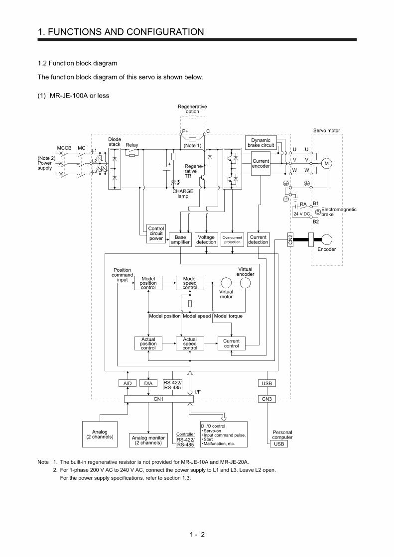
1.2 Function block diagram
The function block diagram of this servo is shown below.
(1) MR-JE-100A or less
Model position
Currentcontrol
Actualpositioncontrol
Actualspeedcontrol
Virtualmotor
Virtualencoder
Encoder
(Note 2)Powersupply
MCMCCB
Positioncommand
input
Model speed Model torque
CN
2
Modelpositioncontrol
Modelspeedcontrol
Servo motor
U U
U
C
L3
L2
L1
Dynamicbrake circuit
Currentdetection
Overcurrentprotection
Voltagedetection
Baseamplifier
U
V
W
U
V
W
Diodestack Relay
P+
(Note 1)
+
B
RA
24 V DC
B1
B2
M
Controlcircuitpower
CHARGElamp
Regene-rativeTR
Currentencoder
Regenerativeoption
Electromagneticbrake
CN3
Analog monitor(2 channels)
I/F
USBA/D D/A
USB
Personalcomputer
Analog(2 channels)
Servo-onInput command pulse.StartMalfunction, etc.
CN1
RS-422/RS-485
Controller
RS-422/RS-485
D I/O control
Note 1. The built-in regenerative resistor is not provided for MR-JE-10A and MR-JE-20A.
2. For 1-phase 200 V AC to 240 V AC, connect the power supply to L1 and L3. Leave L2 open.
For the power supply specifications, refer to section 1.3.

1. FUNCTIONS AND CONFIGURATION
1 - 3
(2) MR-JE-200A or more
MCMCCB
Servo motor
U U
U
L3
L2
L1 U
V
W
U
V
W
B
RA
24 V DC
B1
B2
M
CN
2
N- (Note 2)C DP+
+
Cooling fan
(Note 1)Powersupply
Dynamicbrake circuit
Diodestack Relay
CHARGElamp
Regene-rativeTR
Currentencoder
Regenerativeoption
Encoder
Currentdetection
Overcurrentprotection
Voltagedetection
Baseamplifier
Controlcircuitpower
Electromagneticbrake
Model position
Currentcontrol
Actualpositioncontrol
Actualspeedcontrol
Virtualmotor
Virtualencoder
Positioncommand
input
Model speed Model torque
Modelpositioncontrol
Modelspeedcontrol
CN3
Analog monitor(2 channels)
I/F
USBA/D D/A
USB
Personalcomputer
Analog(2 channels)
CN1
Servo-onInput command pulse.StartMalfunction, etc.
D I/O control
RS-422/RS-485
Controller
RS-422/RS-485
Note 1. For the power supply specifications, refer to section 1.3.
2. This is for manufacturer adjustment. Leave this open.
1. FUNCTIONS AND CONFIGURATION
1 - 4
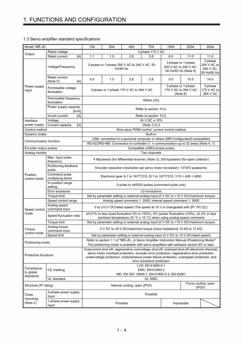
1.3 Servo amplifier standard specifications
Model: MR-JE- 10A 20A 40A 70A 100A 200A 300A
Output Rated voltage 3-phase 170 V AC
Rated current [A] 1.1 1.5 2.8 5.8 6.0 11.0 11.0
Power supply input
Voltage/Frequency 3-phase or 1-phase 200 V AC to 240 V AC, 50
Hz/60 Hz
3-phase or 1-phase 200 V AC to 240 V AC, 50 Hz/60 Hz (Note 6)
3-phase 200 V AC to 240 V AC,
50 Hz/60 Hz
Rated current (Note 5) [A]
0.9 1.5 2.6 3.8 5.0 10.5 14.0
Permissible voltage fluctuation
3-phase or 1-phase 170 V AC to 264 V AC 3-phase or 1-phase
170 V AC to 264 V AC (Note 6)
3-phase 170 V AC to
264 V AC
Permissible frequency fluctuation
Within ±5%
Power supply capacity [kVA]
Refer to section 10.2.
Inrush current [A] Refer to section 10.5.
Interface power supply
Voltage 24 V DC ± 10%
Current capacity [A] (Note 1) 0.3
Control method Sine-wave PWM control, current control method
Dynamic brake Built-in
Communication function USB: connection to a personal computer or others (MR Configurator2-compatible)
RS-422/RS-485: Connection to controller (1: n communication up to 32 axes) (Note 4, 7)
Encoder output pulses Compatible (A/B/Z-phase pulse)
Analog monitor Two channels
Position control mode
Max. input pulse frequency
4 Mpulses/s (for differential receiver) (Note 3), 200 kpulses/s (for open collector)
Positioning feedback pulse
Encoder resolution (resolution per servo motor revolution): 131072 pulses/rev
Command pulse multiplying factor
Electronic gear A:1 to 16777215, B:1 to 16777215, 1/10 < A/B < 4000
In-position range setting
0 pulse to ±65535 pulses (command pulse unit)
Error excessive ±3 revolutions
Torque limit Set by parameter setting or external analog input (0 V DC to +10 V DC/maximum torque)
Speed control mode
Speed control range Analog speed command 1: 2000, internal speed command 1: 5000
Analog speed command input
0 to ±10 V DC/rated speed (The speed at 10 V is changeable with [Pr. PC12].)
Speed fluctuation ratio ±0.01% or less (load fluctuation 0% to 100%), 0% (power fluctuation ±10%), ±0.2% or less
(ambient temperature 25 °C ± 10 °C) when using analog speed command
Torque limit Set by parameter setting or external analog input (0 V DC to +10 V DC/maximum torque)
Torque control mode
Analog torque command input
0 V DC to ±8 V DC/maximum torque (input impedance 10 kΩ to 12 kΩ)
Speed limit Set by parameter setting or external analog input (0 V DC to 10 V DC/rated speed)
Positioning mode Refer to section 1.1 of "MR-JE-_A Servo Amplifier Instruction Manual (Positioning Mode)" The positioning mode is available with servo amplifiers with software version B7 or later.
Protective functions
Overcurrent shut-off, regenerative overvoltage shut-off, overload shut-off (electronic thermal), servo motor overheat protection, encoder error protection, regenerative error protection,
undervoltage protection, instantaneous power failure protection, overspeed protection, and error excessive protection
Compliance to global standards
CE marking LVD: EN 61800-5-1 EMC: EN 61800-3
MD: EN ISO 13849-1, EN 61800-5-2, EN 62061
UL standard UL 508C
Structure (IP rating) Natural cooling, open (IP20) Force cooling, open
(IP20)
Close mounting (Note 2)
3-phase power supply input
Possible
1-phase power supply input
Possible Impossible
1. FUNCTIONS AND CONFIGURATION
1 - 5
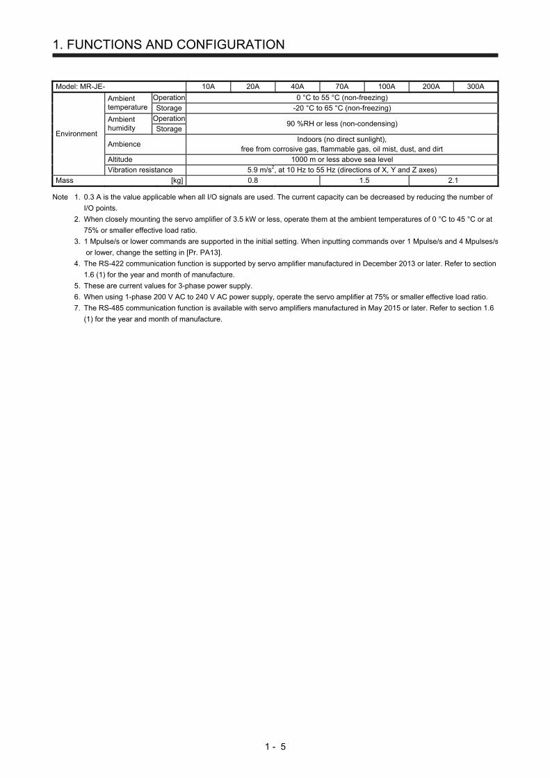
Model: MR-JE- 10A 20A 40A 70A 100A 200A 300A
Environment
Ambient temperature
Operation 0 °C to 55 °C (non-freezing)
Storage -20 °C to 65 °C (non-freezing)
Ambient humidity
Operation 90 %RH or less (non-condensing)
Storage
Ambience Indoors (no direct sunlight),
free from corrosive gas, flammable gas, oil mist, dust, and dirt
Altitude 1000 m or less above sea level
Vibration resistance 5.9 m/s2, at 10 Hz to 55 Hz (directions of X, Y and Z axes)
Mass [kg] 0.8 1.5 2.1 Note 1. 0.3 A is the value applicable when all I/O signals are used. The current capacity can be decreased by reducing the number of
I/O points.
2. When closely mounting the servo amplifier of 3.5 kW or less, operate them at the ambient temperatures of 0 °C to 45 °C or at
75% or smaller effective load ratio.
3. 1 Mpulse/s or lower commands are supported in the initial setting. When inputting commands over 1 Mpulse/s and 4 Mpulses/s
or lower, change the setting in [Pr. PA13].
4. The RS-422 communication function is supported by servo amplifier manufactured in December 2013 or later. Refer to section
1.6 (1) for the year and month of manufacture.
5. These are current values for 3-phase power supply.
6. When using 1-phase 200 V AC to 240 V AC power supply, operate the servo amplifier at 75% or smaller effective load ratio.
7. The RS-485 communication function is available with servo amplifiers manufactured in May 2015 or later. Refer to section 1.6
(1) for the year and month of manufacture.
1. FUNCTIONS AND CONFIGURATION
1 - 6
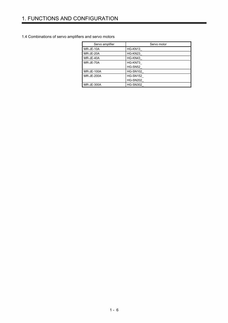
1.4 Combinations of servo amplifiers and servo motors
Servo amplifier Servo motor
MR-JE-10A HG-KN13_
MR-JE-20A HG-KN23_
MR-JE-40A HG-KN43_
MR-JE-70A HG-KN73_ HG-SN52_
MR-JE-100A HG-SN102_
MR-JE-200A HG-SN152_ HG-SN202_
MR-JE-300A HG-SN302_
1. FUNCTIONS AND CONFIGURATION
1 - 7
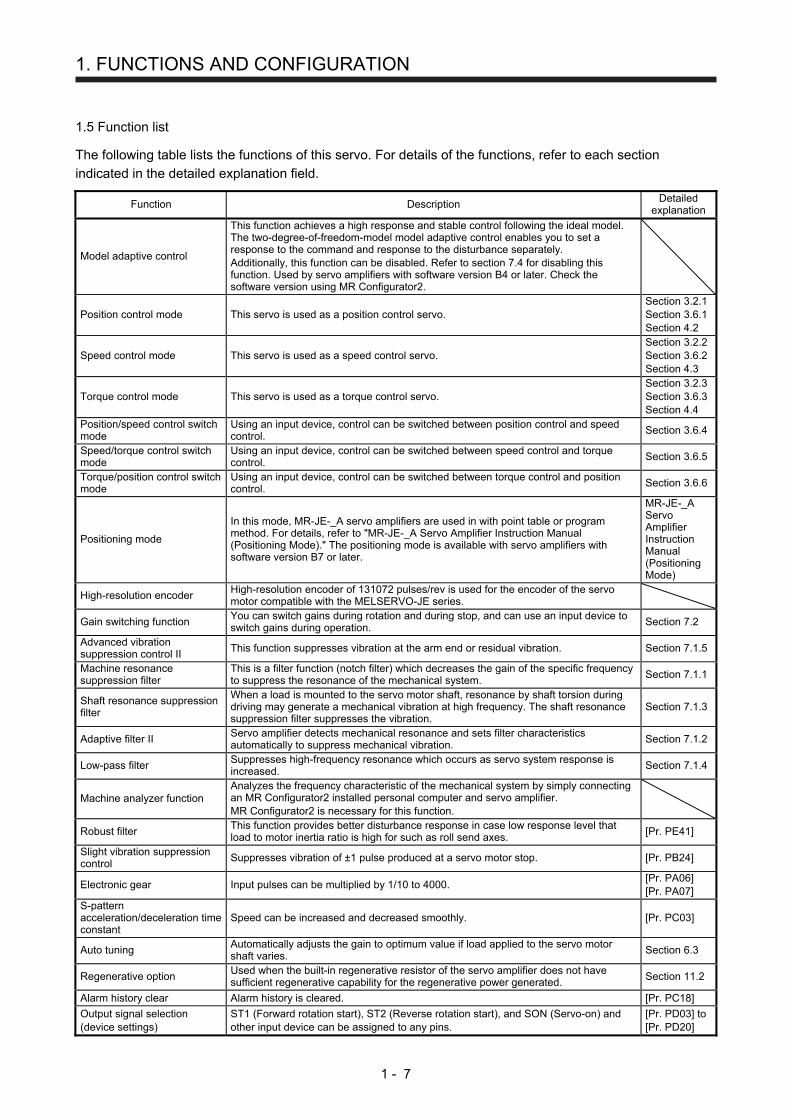
1.5 Function list
The following table lists the functions of this servo. For details of the functions, refer to each section
indicated in the detailed explanation field.
Function Description Detailed
explanation
Model adaptive control
This function achieves a high response and stable control following the ideal model. The two-degree-of-freedom-model model adaptive control enables you to set a response to the command and response to the disturbance separately. Additionally, this function can be disabled. Refer to section 7.4 for disabling this function. Used by servo amplifiers with software version B4 or later. Check the software version using MR Configurator2.
Position control mode This servo is used as a position control servo. Section 3.2.1 Section 3.6.1 Section 4.2
Speed control mode This servo is used as a speed control servo. Section 3.2.2 Section 3.6.2 Section 4.3
Torque control mode This servo is used as a torque control servo. Section 3.2.3 Section 3.6.3 Section 4.4
Position/speed control switch mode
Using an input device, control can be switched between position control and speed control.
Section 3.6.4
Speed/torque control switch mode
Using an input device, control can be switched between speed control and torque control.
Section 3.6.5
Torque/position control switch mode
Using an input device, control can be switched between torque control and position control.
Section 3.6.6
Positioning mode
In this mode, MR-JE-_A servo amplifiers are used in with point table or program method. For details, refer to "MR-JE-_A Servo Amplifier Instruction Manual (Positioning Mode)." The positioning mode is available with servo amplifiers with software version B7 or later.
MR-JE-_A Servo Amplifier Instruction Manual (Positioning Mode)
High-resolution encoder High-resolution encoder of 131072 pulses/rev is used for the encoder of the servo motor compatible with the MELSERVO-JE series.
Gain switching function You can switch gains during rotation and during stop, and can use an input device to switch gains during operation.
Section 7.2
Advanced vibration suppression control II
This function suppresses vibration at the arm end or residual vibration. Section 7.1.5
Machine resonance suppression filter
This is a filter function (notch filter) which decreases the gain of the specific frequency to suppress the resonance of the mechanical system.
Section 7.1.1
Shaft resonance suppression filter
When a load is mounted to the servo motor shaft, resonance by shaft torsion during driving may generate a mechanical vibration at high frequency. The shaft resonance suppression filter suppresses the vibration.
Section 7.1.3
Adaptive filter II Servo amplifier detects mechanical resonance and sets filter characteristics automatically to suppress mechanical vibration.
Section 7.1.2
Low-pass filter Suppresses high-frequency resonance which occurs as servo system response is increased.
Section 7.1.4
Machine analyzer function Analyzes the frequency characteristic of the mechanical system by simply connecting an MR Configurator2 installed personal computer and servo amplifier. MR Configurator2 is necessary for this function.
Robust filter This function provides better disturbance response in case low response level that load to motor inertia ratio is high for such as roll send axes.
[Pr. PE41]
Slight vibration suppression control
Suppresses vibration of ±1 pulse produced at a servo motor stop. [Pr. PB24]
Electronic gear Input pulses can be multiplied by 1/10 to 4000. [Pr. PA06] [Pr. PA07]
S-pattern acceleration/deceleration time constant
Speed can be increased and decreased smoothly. [Pr. PC03]
Auto tuning Automatically adjusts the gain to optimum value if load applied to the servo motor shaft varies.
Section 6.3
Regenerative option Used when the built-in regenerative resistor of the servo amplifier does not have sufficient regenerative capability for the regenerative power generated.
Section 11.2
Alarm history clear Alarm history is cleared. [Pr. PC18]
Output signal selection (device settings)
ST1 (Forward rotation start), ST2 (Reverse rotation start), and SON (Servo-on) and other input device can be assigned to any pins.
[Pr. PD03] to [Pr. PD20]
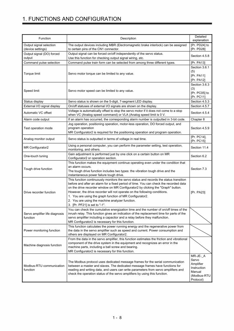
1. FUNCTIONS AND CONFIGURATION
1 - 8
Function Description Detailed
explanation
Output signal selection (device settings)
The output devices including MBR (Electromagnetic brake interlock) can be assigned to certain pins of the CN1 connector.
[Pr. PD24] to [Pr. PD28]
Output signal (DO) forced output
Output signal can be forced on/off independently of the servo status. Use this function for checking output signal wiring, etc.
Section 4.5.8
Command pulse selection Command pulse train form can be selected from among three different types. [Pr. PA13]
Torque limit Servo motor torque can be limited to any value.
Section 3.6.1 (5) [Pr. PA11] [Pr. PA12]
Speed limit Servo motor speed can be limited to any value.
Section 3.6.3 (3) [Pr. PC05] to [Pr. PC11]
Status display Servo status is shown on the 5-digit, 7-segment LED display. Section 4.5.3
External I/O signal display On/off statuses of external I/O signals are shown on the display. Section 4.5.7
Automatic VC offset Voltage is automatically offset to stop the servo motor if it does not come to a stop when VC (Analog speed command) or VLA (Analog speed limit is 0 V.
Section 4.5.4
Alarm code output If an alarm has occurred, the corresponding alarm number is outputted in 3-bit code. Chapter 8
Test operation mode Jog operation, positioning operation, motor-less operation, DO forced output, and program operation MR Configurator2 is required for the positioning operation and program operation.
Section 4.5.9
Analog monitor output Servo status is outputted in terms of voltage in real time. [Pr. PC14], [Pr. PC15]
MR Configurator2 Using a personal computer, you can perform the parameter setting, test operation, monitoring, and others.
Section 11.4
One-touch tuning Gain adjustment is performed just by one click on a certain button on MR Configurator2 or operation section.
Section 6.2
Tough drive function
This function makes the equipment continue operating even under the condition that an alarm occurs. The tough drive function includes two types: the vibration tough drive and the instantaneous power failure tough drive.
Section 7.3
Drive recorder function
This function continuously monitors the servo status and records the status transition before and after an alarm for a fixed period of time. You can check the recorded data on the drive recorder window on MR Configurator2 by clicking the "Graph" button. However, the drive recorder will not operate on the following conditions. 1. You are using the graph function of MR Configurator2. 2. You are using the machine analyzer function. 3. [Pr. PF21] is set to "-1".
[Pr. PA23]
Servo amplifier life diagnosis function
You can check the cumulative energization time and the number of on/off times of the inrush relay. This function gives an indication of the replacement time for parts of the servo amplifier including a capacitor and a relay before they malfunction. MR Configurator2 is necessary for this function.
Power monitoring function This function calculates the power running energy and the regenerative power from the data in the servo amplifier such as speed and current. Power consumption and others are displayed on MR Configurator2.
Machine diagnosis function
From the data in the servo amplifier, this function estimates the friction and vibrational component of the drive system in the equipment and recognizes an error in the machine parts, including a ball screw and bearing. MR Configurator2 is necessary for this function.
Modbus-RTU communication function
The Modbus protocol uses dedicated message frames for the serial communication between a master and slaves. The dedicated message frames have functions for reading and writing data, and users can write parameters from servo amplifiers and check the operation status of the servo amplifiers by using this function.
MR-JE-_A Servo Amplifier Instruction Manual (Modbus-RTU Protocol)

1. FUNCTIONS AND CONFIGURATION
1 - 9
1.6 Model designation
(1) Rating plate
The following shows an example of rating plate for explanation of each item.
Serial numberModelCapacityApplicable power supplyRated output currentStandard, Manual numberAmbient temperatureIP ratingKC certification numberThe year and month of manufactureCountry of origin
TOKYO 100-8310, JAPAN MADE IN JAPAN
DATE: 2014-11
MR-JE-10ASER. S4Y001001
AC SERVO
POWERINPUTOUTPUTSTD.: IEC/EN61800-5-1 MAN.: IB(NA)0300194Max. Surrounding Air Temp.: 55°CIP20
: 100W: 3AC/200-240V 0.9A/1.5A 50/60Hz: 3PH170V 0-360Hz 1.1A
KCC-REI-MEK-TC300A745G51
(2) Model
The following describes what each block of a model name indicates.
SeriesRated output
General-purpose interface
Symbol Rated output [kW]
10 0.1
20 0.2
40 0.4
70 0.75
100 1
200 2
300 3

1. FUNCTIONS AND CONFIGURATION
1 - 10
1.7 Structure
1.7.1 Parts identification
(1) MR-JE-100A or less
(1)
(2)
(7)
(3)
(4)
(5)
(8)
(6)
(9)
Bottom
Side
No. Name/Application Detailed explanati
on
(1) Display The 5-digit, 7-segment LED shows the servo status and the alarm number.
Section 4.5
(2)
Operation section Used to perform status display, diagnostic, alarm, and parameter setting operations. Push the "MODE" and "SET" buttons at the same time for 3 s or more to switch to the one-touch tuning mode.
Used to change the mode.
Used to change thedisplay or data in eachmode.
Used to set data.
To the one-touch tuningmode
Section 4.5
Section 6.2
(3) USB communication connector (CN3) Connect with the personal computer.
Section 11.4
(4)
I/O signal connector (CN1) Digital I/O signal, analog input signal, analog monitor output signal, and RS-422/RS-485 communication controller are connected.
Section 3.2
Section 3.4
Chapter 12
(5) Encoder connector (CN2) Used to connect the servo motor encoder.
Section 3.4
(6)
Power connector (CNP1) Input power supply, built-in regenerative resistor, regenerative option, and servo motor are connected.
Section 3.1
Section 3.3
(7) Rating plate Section
1.6
(8) Charge lamp When the main circuit is charged, this will light up. While this lamp is lit, do not reconnect the cables.
(9)
Protective earth (PE) terminal Grounding terminal
Section 3.1
Section 3.3
1. FUNCTIONS AND CONFIGURATION
1 - 11
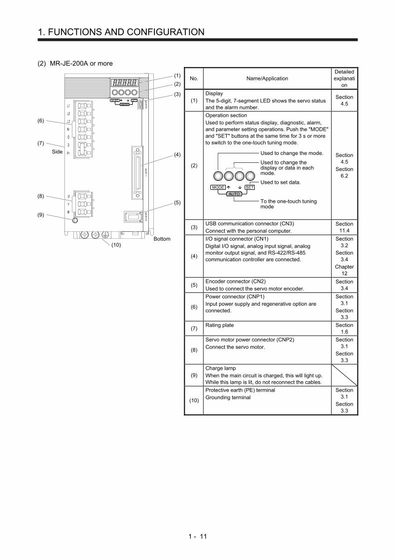
(2) MR-JE-200A or more
(1)
(2)
(6)
(7)
(8)
(9)
(10)Bottom
Side (4)
(5)
(3)
No. Name/Application Detailed explanati
on
(1) Display The 5-digit, 7-segment LED shows the servo status and the alarm number.
Section 4.5
(2)
Operation section Used to perform status display, diagnostic, alarm, and parameter setting operations. Push the "MODE" and "SET" buttons at the same time for 3 s or more to switch to the one-touch tuning mode.
Used to change the mode.
Used to change thedisplay or data in eachmode.
Used to set data.
To the one-touch tuningmode
Section 4.5
Section 6.2
(3) USB communication connector (CN3) Connect with the personal computer.
Section 11.4
(4)
I/O signal connector (CN1) Digital I/O signal, analog input signal, analog monitor output signal, and RS-422/RS-485 communication controller are connected.
Section 3.2
Section 3.4
Chapter 12
(5) Encoder connector (CN2) Used to connect the servo motor encoder.
Section 3.4
(6)
Power connector (CNP1) Input power supply and regenerative option are connected.
Section 3.1
Section 3.3
(7) Rating plate Section
1.6
(8)
Servo motor power connector (CNP2) Connect the servo motor.
Section 3.1
Section 3.3
(9) Charge lamp When the main circuit is charged, this will light up. While this lamp is lit, do not reconnect the cables.
(10)
Protective earth (PE) terminal Grounding terminal
Section 3.1
Section 3.3

1. FUNCTIONS AND CONFIGURATION
1 - 12
1.8 Configuration including peripheral equipment
CAUTION Connecting a servo motor of the wrong axis to U, V, W, or CN2 of the servo
amplifier may cause a malfunction.
POINT
Equipment other than the servo amplifier and servo motor are optional or
recommended products.
(1) MR-JE-100A or less
The diagram shows MR-JE-40A.
Power factorimproving ACreactor(FR-HAL)
Line noisefilter(FR-BSF01)
CN3
Servo motor
Personalcomputer
MR Configurator2
CN1
CN2
W
V
U
L1
L2
L3
(Note 2)Magneticcontactor(MC)
Molded-casecircuit breaker
R S T
Junction terminal block
(Note 1)Powersupply
Note 1. A 1-phase 200 V AC to 240 V AC power supply may be used with the servo amplifier of MR-JE-70A or less. For 1-phase 200 V AC to 240 V AC, connect the power supply to L1 and L3. Leave L2 open. For the power supply specifications, refer to section 1.3.
2. Depending on the power supply voltage and operation pattern, bus voltage can decrease. This can shift the mode to the dynamic brake deceleration during forced stop deceleration. When dynamic brake deceleration is not required, slow the time to turn off the magnetic contactor.
1. FUNCTIONS AND CONFIGURATION
1 - 13
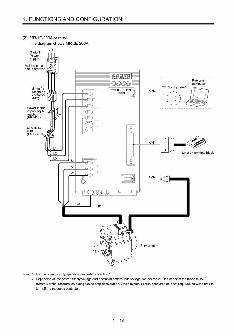
(2) MR-JE-200A or more
The diagram shows MR-JE-200A.
Power factorimproving ACreactor(FR-HAL)
Line noisefilter(FR-BSF01)
CN3
Personalcomputer
MR Configurator2
CN1
CN2W
V
U
L1
L2
L3
(Note 2)Magneticcontactor(MC)
Molded-casecircuit breaker
R S T
Junction terminal block
(Note 1)Powersupply
Servo motor
Note 1. For the power supply specifications, refer to section 1.3.
2. Depending on the power supply voltage and operation pattern, bus voltage can decrease. This can shift the mode to the
dynamic brake deceleration during forced stop deceleration. When dynamic brake deceleration is not required, slow the time to
turn off the magnetic contactor.

1. FUNCTIONS AND CONFIGURATION
1 - 14
MEMO
2. INSTALLATION
2 - 1
2. INSTALLATION
WARNING
To prevent electric shock, ground each equipment securely.
CAUTION
Stacking in excess of the specified number of product packages is not allowed.
Do not hold the lead wire of the regenerative resistor when transporting the servo
amplifier.
Install the equipment on incombustible material. Installing them directly or close to
combustibles will lead to a fire.
Install the servo amplifier and the servo motor in a load-bearing place in
accordance with the Instruction Manual.
Do not get on or put heavy load on the equipment. Otherwise, it may cause injury.
Use the equipment within the specified environment. For the environment, refer to
section 1.3.
Provide an adequate protection to prevent screws and other conductive matter, oil
and other combustible matter from entering the servo amplifier.
Do not block the intake and exhaust areas of the servo amplifier. Otherwise, it
may cause a malfunction.
Do not drop or strike the servo amplifier. Isolate it from all impact loads.
Do not install or operate the servo amplifier which has been damaged or has any
parts missing.
When the product has been stored for an extended period of time, contact your
local sales office.
When handling the servo amplifier, be careful about the edged parts such as
corners of the servo amplifier.
The servo amplifier must be installed in a metal cabinet.
When fumigants that contain halogen materials such as fluorine, chlorine,
bromine, and iodine are used for disinfecting and protecting wooden packaging
from insects, they cause malfunction when entering our products. Please take
necessary precautions to ensure that remaining materials from fumigant do not
enter our products, or treat packaging with methods other than fumigation (heat
method). Additionally, disinfect and protect wood from insects before packing
products.

2. INSTALLATION
2 - 2
2.1 Installation direction and clearances
CAUTION
The equipment must be installed in the specified direction. Otherwise, it may
cause a malfunction.
Leave specified clearances between the servo amplifier and the cabinet walls or
other equipment. Otherwise, it may cause a malfunction.
MR-JE-40A to MR-JE-100A have a regenerative resistor on their back face. The regenerative resistor
generates heat of 100 ˚C higher than the ambient temperature. Please fully consider heat dissipation,
installation position, etc. when mounting it.
(1) Installation clearances of the servo amplifier
(a) Installation of one servo amplifier
40 mmor more
10 mmor more
10 mmor more
40 mmor more
Servoamplifier
Cabinet Cabinet
Wiring allowance80 mmor more
Top
Bottom

2. INSTALLATION
2 - 3
(b) Installation of two or more servo amplifiers
POINT
Close mounting is possible depending on the capacity of the servo amplifier.
Refer to section 1.3 for availability of close mounting.
Leave a large clearance between the top of the servo amplifier and the cabinet walls, and install a
cooling fan to prevent the internal temperature of the cabinet from exceeding the environment.
When mounting the servo amplifiers closely, leave a clearance of 1 mm between the adjacent servo
amplifiers in consideration of mounting tolerances. In this case, keep the ambient temperature within
0 ˚C to 45 ˚C or use the servo amplifier with 75% or less of the effective load ratio.
100 mm or more
10 mm or more
30 mmor more
30 mmor more
40 mm or more
Cabinet
Top
Bottom
100 mm or more
1 mm
30 mmor more
40 mm or more
Cabinet
1 mm
Leaving clearance Mounting closely
(2) Others
When using heat generating equipment such as the regenerative option, install them with full
consideration of heat generation so that the servo amplifier is not affected.
Install the servo amplifier on a perpendicular wall in the correct vertical direction.
2.2 Keep out foreign materials
(1) When drilling in the cabinet, prevent drill chips and wire fragments from entering the servo amplifier.
(2) Prevent oil, water, metallic dust, etc. from entering the servo amplifier through openings in the cabinet or
a cooling fan installed on the ceiling.
(3) When installing the cabinet in a place where toxic gas, dirt and dust exist, conduct an air purge (force
clean air into the cabinet from outside to make the internal pressure higher than the external pressure) to
prevent such materials from entering the cabinet.

2. INSTALLATION
2 - 4
2.3 Encoder cable stress
(1) The way of clamping the cable must be fully examined so that bending stress and cable's own weight
stress are not applied to the cable connection.
(2) For use in any application where the servo motor moves, fix the cables (encoder, power supply, and
brake) with having some slack from the connector connection part of the servo motor to avoid putting
stress on the connector connection part. Use the optional encoder cable within the bending life range.
Use the power supply and brake wiring cables within the bending life of the cables.
(3) Avoid any probability that the cable sheath might be cut by sharp chips, rubbed by a machine corner or
stamped by workers or vehicles.
(4) For installation on a machine where the servo motor moves, the flexing radius should be made as large
as possible. Refer to section 10.4 for the bending life.
2.4 Inspection items
WARNING
Before starting maintenance and/or inspection, turn off the power and wait for 15
minutes or more until the charge lamp turns off. Otherwise, an electric shock may
occur. In addition, when confirming whether the charge lamp is off or not, always
confirm it from the front of the servo amplifier.
To avoid an electric shock, only qualified personnel should attempt inspections.
For repair and parts replacement, contact your local sales office.
CAUTION Do not perform insulation resistance test on the servo amplifier. Otherwise, it may
cause a malfunction.
Do not disassemble and/or repair the equipment on customer side.
It is recommended that the following points periodically be checked.
(1) Check for loose terminal block screws. Retighten any loose screws.
(2) Check the cables and the like for scratches or cracks. Inspect them periodically according to operating
conditions especially when the servo motor is movable.
(3) Check that the connector is securely connected to the servo amplifier.
(4) Check that the wires are not coming out from the connector.
(5) Check for dust accumulation on the servo amplifier.
(6) Check for unusual noise generated from the servo amplifier.
2. INSTALLATION
2 - 5
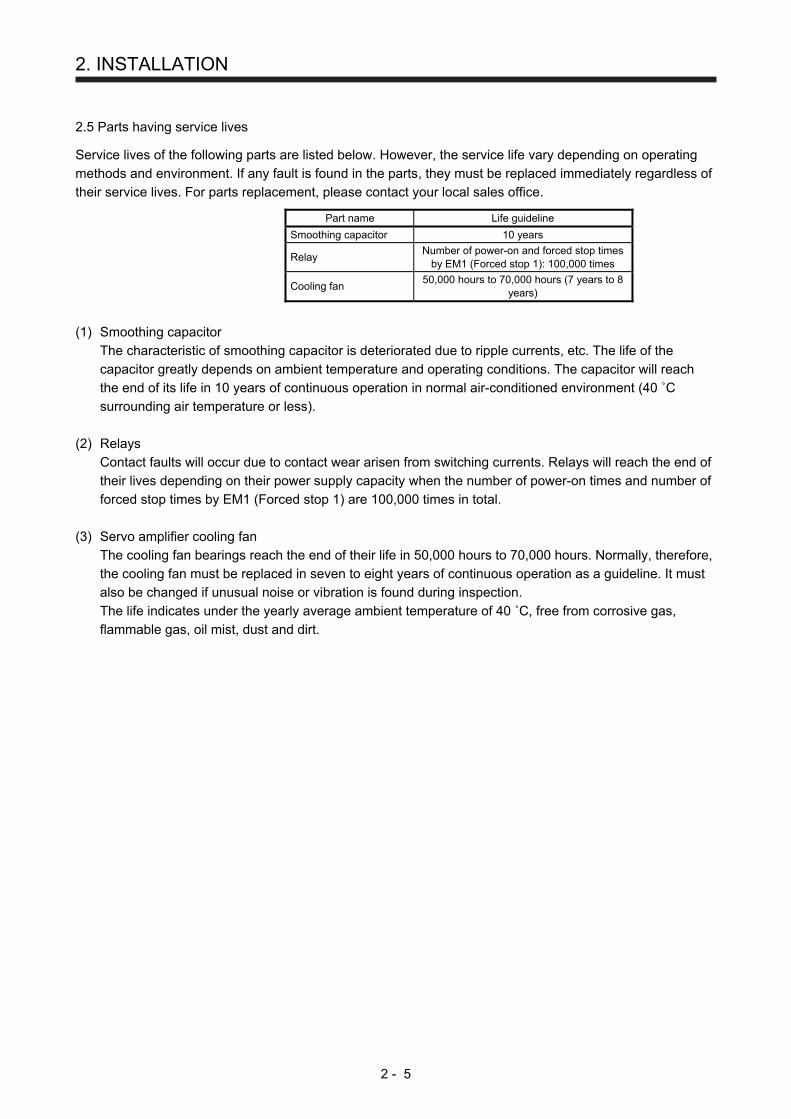
2.5 Parts having service lives
Service lives of the following parts are listed below. However, the service life vary depending on operating
methods and environment. If any fault is found in the parts, they must be replaced immediately regardless of
their service lives. For parts replacement, please contact your local sales office.
Part name Life guideline
Smoothing capacitor 10 years
Relay Number of power-on and forced stop times
by EM1 (Forced stop 1): 100,000 times
Cooling fan 50,000 hours to 70,000 hours (7 years to 8
years)
(1) Smoothing capacitor
The characteristic of smoothing capacitor is deteriorated due to ripple currents, etc. The life of the
capacitor greatly depends on ambient temperature and operating conditions. The capacitor will reach
the end of its life in 10 years of continuous operation in normal air-conditioned environment (40 ˚C
surrounding air temperature or less).
(2) Relays
Contact faults will occur due to contact wear arisen from switching currents. Relays will reach the end of
their lives depending on their power supply capacity when the number of power-on times and number of
forced stop times by EM1 (Forced stop 1) are 100,000 times in total.
(3) Servo amplifier cooling fan
The cooling fan bearings reach the end of their life in 50,000 hours to 70,000 hours. Normally, therefore,
the cooling fan must be replaced in seven to eight years of continuous operation as a guideline. It must
also be changed if unusual noise or vibration is found during inspection.
The life indicates under the yearly average ambient temperature of 40 ˚C, free from corrosive gas,
flammable gas, oil mist, dust and dirt.

2. INSTALLATION
2 - 6
MEMO

3. SIGNALS AND WIRING
3 - 1
3. SIGNALS AND WIRING
WARNING
Any person who is involved in wiring should be fully competent to do the work. Before wiring, turn off the power and wait for 15 minutes or more until the charge lamp turns off. Otherwise, an electric shock may occur. In addition, when confirming whether the charge lamp is off or not, always confirm it from the front of the servo amplifier. Ground the servo amplifier and servo motor securely. Do not attempt to wire the servo amplifier and servo motor until they have been installed. Otherwise, it may cause an electric shock. The cables should not be damaged, stressed, loaded, or pinched. Otherwise, it may cause an electric shock. To avoid an electric shock, insulate the connections of the power supply terminals.
CAUTION
Before removing the CNP1 connector from MR-JE-40A to MR-JE-100A, disconnect the lead wires of the regenerative resistor from the CNP1 connector. Wire the equipment correctly and securely. Otherwise, the servo motor may operate unexpectedly, resulting in injury. Connect cables to the correct terminals. Otherwise, a burst, damage, etc. may occur. Ensure that polarity (+/-) is correct. Otherwise, a burst, damage, etc. may occur. The surge absorbing diode installed to the DC relay for control output should be fitted in the specified direction. Otherwise, the emergency stop and other protective circuits may not operate.
DOCOM
Control outputsignal
Servo amplifier
RA
For sink output interface
24 V DC
DOCOM
Control outputsignal
24 V DCServo amplifier
RA
For source output interface
Use a noise filter, etc. to minimize the influence of electromagnetic interference. Electromagnetic interference may be given to the electronic equipment used near the servo amplifier. Do not install a power capacitor, surge killer or radio noise filter (optional FR-BIF) with the power line of the servo motor. When using the regenerative resistor, switch power off with the alarm signal. Otherwise, a transistor fault or the like may overheat the regenerative resistor, causing a fire. Do not modify the equipment. Connect the servo amplifier power output (U, V, and W) to the servo motor power input (U, V, and W) directly. Do not let a magnetic contactor, etc. intervene. Otherwise, it may cause a malfunction.
U
Servo motor
MV
W
U
V
W
U
MV
W
U
V
W
Servo amplifier Servo motorServo amplifier
Connecting a servo motor of the wrong axis to U, V, W, or CN2 of the servo amplifier may cause a malfunction.

3. SIGNALS AND WIRING
3 - 2
3.1 Input power supply circuit
CAUTION
Always connect a magnetic contactor between the power supply and the power
supply (L1, L2, and L3) of the servo amplifier, in order to configure a circuit that
shuts down the power supply on the side of the servo amplifier’s power supply. If
a magnetic contactor is not connected, continuous flow of a large current may
cause a fire when the servo amplifier malfunctions.
Use ALM (Malfunction) to switch power off. Not doing so may cause a fire when a
regenerative transistor malfunctions or the like may overheat the regenerative
resistor.
Before removing the CNP1 connector from MR-JE-40A to MR-JE-100A,
disconnect the lead wires of the regenerative resistor from the CNP1 connector.
Not doing so may break the lead wires of the regenerative resistor.
Check the servo amplifier model, and then input proper voltage to the servo
amplifier power supply. If input voltage exceeds the upper limit of the
specification, the servo amplifier will break down.
The servo amplifier has a built-in surge absorber (varistor) to reduce noise and to
suppress lightning surge. The varistor can break down due to its aged
deterioration. To prevent a fire, use a molded-case circuit breaker or fuse for input
power supply.
Connecting a servo motor of the wrong axis to U, V, W, or CN2 of the servo
amplifier may cause a malfunction.
The N- terminal is not a neutral point of the power supply. Incorrect wiring will
cause a burst, damage, etc.
POINT
EM2 has the same function as EM1 in the torque control mode.
When a 1-phase 200 V AC to 240 V AC power supply is used, the connection
destination differs depending on the servo amplifier. Ensure that the connection
destination is correct.
Configure the wirings so that the power supply is shut off and SON (Servo-on) is turned off after deceleration
to a stop due to an alarm occurring, enabled servo forced stop, etc. A molded-case circuit breaker (MCCB)
must be used with the input cables of the main circuit power supply.
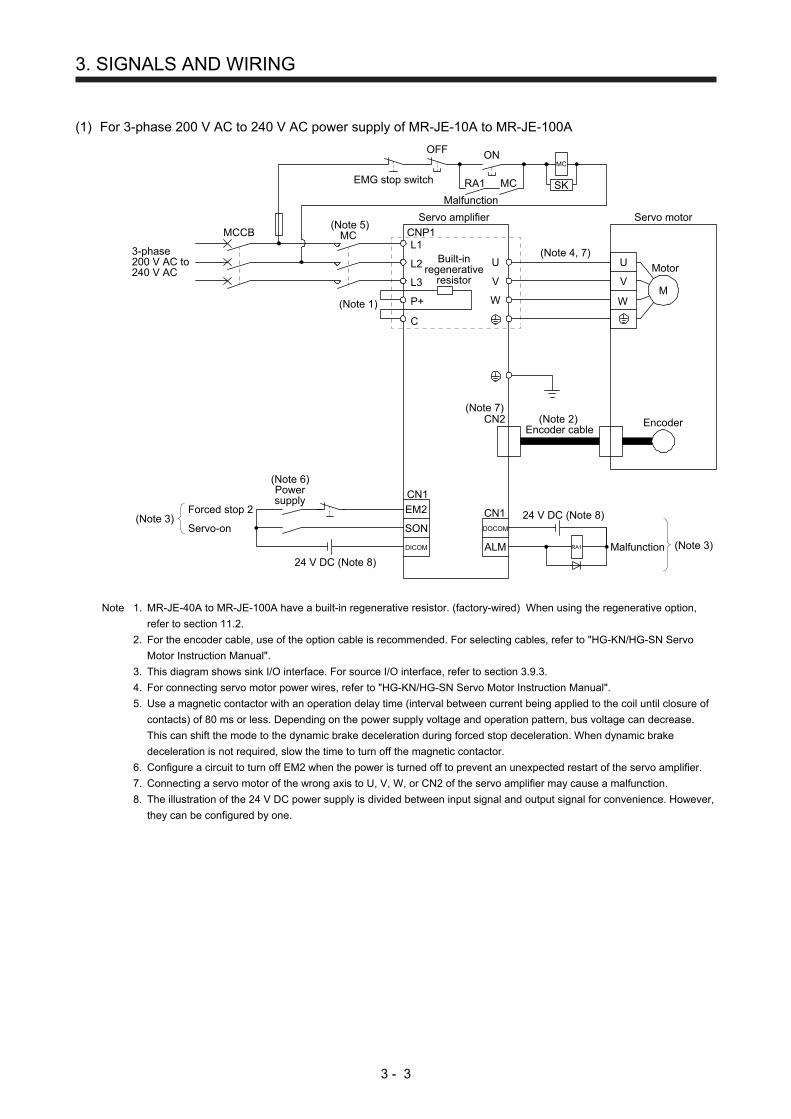
3. SIGNALS AND WIRING
3 - 3
(1) For 3-phase 200 V AC to 240 V AC power supply of MR-JE-10A to MR-JE-100A
(Note 5)MC
ALM
DOCOM
CN1
(Note 3)
24 V DC (Note 8)
24 V DC (Note 8)
MalfunctionRA1
L1
L2
L3
3-phase200 V AC to240 V AC
Servo amplifier
U
V
W(Note 1)
CNP1
Servo motor
U
V
WM
Motor
EncoderCN2 (Note 2)Encoder cable
(Note 4, 7)
RA1
Malfunction
OFF
MC
ONMC
SKEMG stop switch
CN1
Forced stop 2
Servo-on(Note 3)
EM2
SON
DICOM
(Note 6)Powersupply
MCCB
(Note 7)
C
P+
Built-inregenerative
resistor
Note 1. MR-JE-40A to MR-JE-100A have a built-in regenerative resistor. (factory-wired) When using the regenerative option,
refer to section 11.2.
2. For the encoder cable, use of the option cable is recommended. For selecting cables, refer to "HG-KN/HG-SN Servo
Motor Instruction Manual".
3. This diagram shows sink I/O interface. For source I/O interface, refer to section 3.9.3.
4. For connecting servo motor power wires, refer to "HG-KN/HG-SN Servo Motor Instruction Manual".
5. Use a magnetic contactor with an operation delay time (interval between current being applied to the coil until closure of
contacts) of 80 ms or less. Depending on the power supply voltage and operation pattern, bus voltage can decrease.
This can shift the mode to the dynamic brake deceleration during forced stop deceleration. When dynamic brake
deceleration is not required, slow the time to turn off the magnetic contactor.
6. Configure a circuit to turn off EM2 when the power is turned off to prevent an unexpected restart of the servo amplifier.
7. Connecting a servo motor of the wrong axis to U, V, W, or CN2 of the servo amplifier may cause a malfunction.
8. The illustration of the 24 V DC power supply is divided between input signal and output signal for convenience. However,
they can be configured by one.
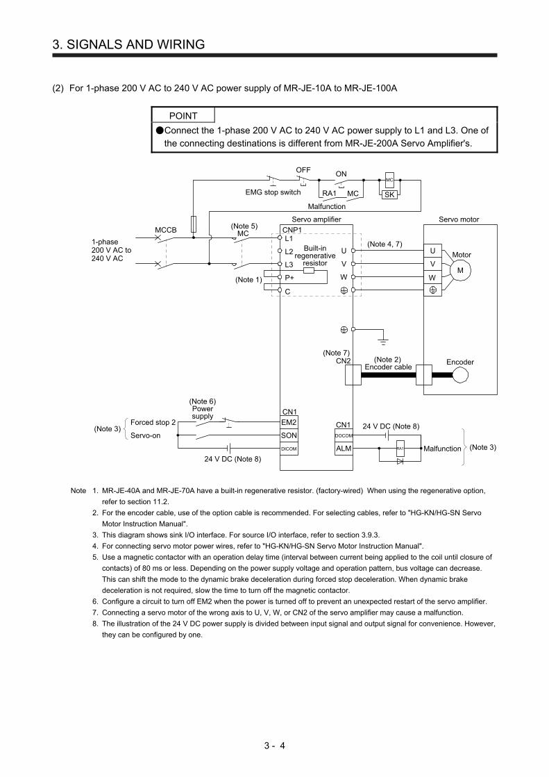
3. SIGNALS AND WIRING
3 - 4
(2) For 1-phase 200 V AC to 240 V AC power supply of MR-JE-10A to MR-JE-100A
POINT
Connect the 1-phase 200 V AC to 240 V AC power supply to L1 and L3. One of
the connecting destinations is different from MR-JE-200A Servo Amplifier's.
(Note 5)MC
ALM
DOCOM
CN1
(Note 3)
24 V DC (Note 8)
24 V DC (Note 8)
MalfunctionRA1
L1
L2
L3
1-phase200 V AC to240 V AC
Servo amplifier
U
V
W(Note 1)
CNP1
Servo motor
U
V
WM
Motor
EncoderCN2 (Note 2)Encoder cable
(Note 4, 7)
CN1
Forced stop 2
Servo-on(Note 3)
EM2
SON
DICOM
(Note 6)Powersupply
MCCB
(Note 7)
C
P+
Built-inregenerative
resistor
RA1
OFF
MC
ONMC
SKEMG stop switch
Malfunction
Note 1. MR-JE-40A and MR-JE-70A have a built-in regenerative resistor. (factory-wired) When using the regenerative option,
refer to section 11.2.
2. For the encoder cable, use of the option cable is recommended. For selecting cables, refer to "HG-KN/HG-SN Servo
Motor Instruction Manual".
3. This diagram shows sink I/O interface. For source I/O interface, refer to section 3.9.3.
4. For connecting servo motor power wires, refer to "HG-KN/HG-SN Servo Motor Instruction Manual".
5. Use a magnetic contactor with an operation delay time (interval between current being applied to the coil until closure of
contacts) of 80 ms or less. Depending on the power supply voltage and operation pattern, bus voltage can decrease.
This can shift the mode to the dynamic brake deceleration during forced stop deceleration. When dynamic brake
deceleration is not required, slow the time to turn off the magnetic contactor.
6. Configure a circuit to turn off EM2 when the power is turned off to prevent an unexpected restart of the servo amplifier.
7. Connecting a servo motor of the wrong axis to U, V, W, or CN2 of the servo amplifier may cause a malfunction.
8. The illustration of the 24 V DC power supply is divided between input signal and output signal for convenience. However,
they can be configured by one.

3. SIGNALS AND WIRING
3 - 5
(3) For 3-phase 200 V AC to 240 V AC power supply of MR-JE-200A or MR-JE-300A
(Note 5)MC
ALM
DOCOM
CN1
(Note 3)
24 V DC (Note 8)
24 V DC (Note 8)
MalfunctionRA1
3-phase200 V AC to240 V AC
Servo amplifier Servo motor
U
V
WM
Motor
EncoderCN2 (Note 2)Encoder cable
(Note 4, 7)
CN1
Forced stop 2
Servo-on(Note 3)
EM2
SON
DICOM
(Note 6)Powersupply
MCCB
(Note 7)
L1
L2
L3
P+
N-
D
C
U
V
W
(Note 1)
CNP1
CNP2
RA1
OFF
MC
ONMC
SKEMG stop switch
Malfunction
Note 1. Always connect between P+ and D terminals. (factory-wired) When using the regenerative option, refer to section 11.2.
2. For the encoder cable, use of the option cable is recommended. For selecting cables, refer to "HG-KN/HG-SN Servo
Motor Instruction Manual".
3. This diagram shows sink I/O interface. For source I/O interface, refer to section 3.9.3.
4. For connecting servo motor power wires, refer to "HG-KN/HG-SN Servo Motor Instruction Manual".
5. Use a magnetic contactor with an operation delay time (interval between current being applied to the coil until closure of
contacts) of 80 ms or less. Depending on the power supply voltage and operation pattern, bus voltage can decrease.
This can shift the mode to the dynamic brake deceleration during forced stop deceleration. When dynamic brake
deceleration is not required, slow the time to turn off the magnetic contactor.
6. Configure a circuit to turn off EM2 when the power is turned off to prevent an unexpected restart of the servo amplifier.
7. Connecting a servo motor of the wrong axis to U, V, W, or CN2 of the servo amplifier may cause a malfunction.
8. The illustration of the 24 V DC power supply is divided between input signal and output signal for convenience. However,
they can be configured by one.

3. SIGNALS AND WIRING
3 - 6
(4) For 1-phase 200 V AC to 240 V AC power supply of MR-JE-200A
POINT
Connect the 1-phase 200 V AC to 240 V AC power supply to L1 and L2. One of
the connecting destinations is different from MR-JE-100A or less Servo
Amplifier's.
ALM
DOCOM
CN1
RA1
CN1
EM2
SON
DICOM
L1
L2
L3
P+
N-
D
C
U
V
W
CNP1
CNP2
(Note 5)MC
(Note 3)
24 V DC (Note 8)
24 V DC (Note 8)
Malfunction
1-phase200 V AC to240 V AC
Servo amplifier
(Note 1)
Servo motor
U
V
WM
Motor
EncoderCN2 (Note 2)Encoder cable
(Note 4, 7)
Forced stop 2
Servo-on(Note 3)
(Note 6)Powersupply
MCCB
(Note 7)
RA1
OFF
MC
ONMC
SKEMG stop switch
Malfunction
Note 1. Always connect between P+ and D terminals. (factory-wired) When using the regenerative option, refer to section 11.2.
2. For the encoder cable, use of the option cable is recommended. For cable selection, refer to "HG-KN/HG-SN Servo
Motor Instruction Manual".
3. This is for the sink I/O interface. For source I/O interface, refer to section 3.9.3.
4. For connection of servo motor power wires, refer to "HG-KN/HG-SN Servo Motor Instruction Manual".
5. Use a magnetic contactor with an operation delay time (interval between current being applied to the coil until closure of
contacts) of 80 ms or less. Depending on the power supply voltage and operation pattern, bus voltage can decrease.
This can shift the mode to the dynamic brake deceleration during forced stop deceleration. When dynamic brake
deceleration is not required, slow the time to turn off the magnetic contactor.
6. Configure a circuit to turn off EM2 when the power is turned off to prevent an unexpected restart of the servo amplifier.
7. Connecting a servo motor of the wrong axis to U, V, W, or CN2 of the servo amplifier may cause a malfunction.
8. The illustration of the 24 V DC power supply is divided between input signal and output signal for convenience. However,
they can be configured by one.
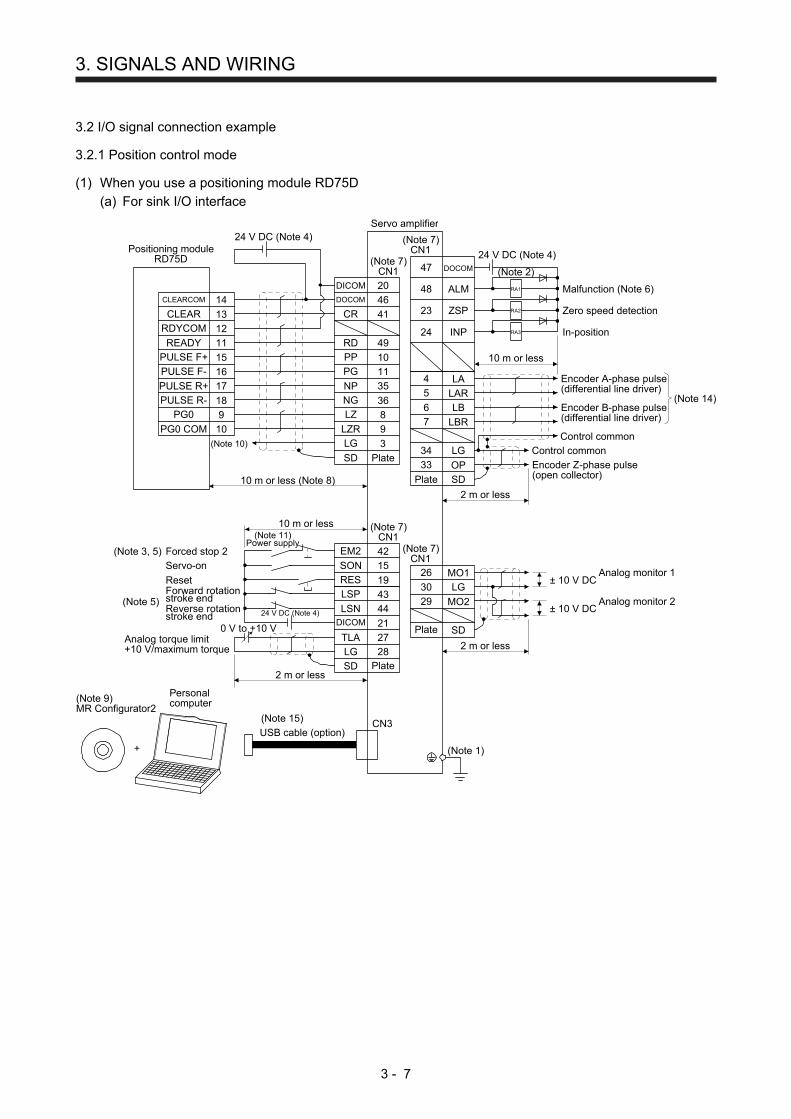
3. SIGNALS AND WIRING
3 - 7
3.2 I/O signal connection example
3.2.1 Position control mode
(1) When you use a positioning module RD75D
(a) For sink I/O interface
Servo amplifier
2 m or less
26 MO1
30 LG
29 MO2
(Note 7)CN1
± 10 V DC
± 10 V DC
Analog monitor 1
(Note 2)
Malfunction (Note 6)
Zero speed detection
Encoder A-phase pulse(differential line driver)
47 DOCOM
48 ALM
23 ZSP
24 INP
4 LA5 LAR
6 LB
7 LBR
34 LG
33 OP
SD
10 m or less
2 m or less
Encoder B-phase pulse(differential line driver)
Control common
Encoder Z-phase pulse(open collector)
(Note 7)CN1
LG
DICOM
10 m or less (Note 8)
41
20
46
49
10
11
35
9
3
36
CLEARCOM
12
15
16
14
13
11
CLEAR
RDYCOM
READY
PULSE F+
PULSE F-
PG0
PG0 COM
PULSE R+
PULSE R- 18
10
17
9
DOCOM
CR
RD
PP
PG
NP
NG
LZ
LZR
8
(Note 10)
(Note 7)CN1
Positioning moduleRD75D
In-position
Control commonSD
RA1
RA2
RA3
24 V DC (Note 4)
24 V DC (Note 4)
24 V DC (Note 4)
Plate
(Note 1)
2 m or less
10 m or less
0 V to +10 V
42
15
19
43
44
21
27
SD
Plate
Plate
Plate
SD
EM2
SON
RES
LSP
LSNDICOM
TLA
LG 28
(Note 7)CN1
Forced stop 2
Servo-on
ResetForward rotationstroke endReverse rotationstroke end
(Note 3, 5)
(Note 5)
+
USB cable (option)
(Note 9)MR Configurator2
CN3
Analog torque limit+10 V/maximum torque
Personalcomputer
(Note 11)Power supply
Analog monitor 2
(Note 15)
(Note 14)
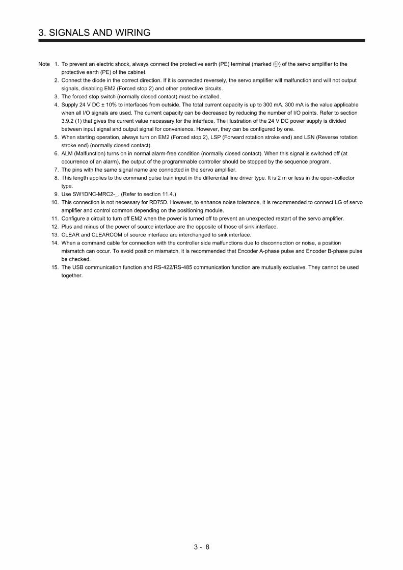
3. SIGNALS AND WIRING
3 - 8
Note 1. To prevent an electric shock, always connect the protective earth (PE) terminal (marked ) of the servo amplifier to the
protective earth (PE) of the cabinet.
2. Connect the diode in the correct direction. If it is connected reversely, the servo amplifier will malfunction and will not output
signals, disabling EM2 (Forced stop 2) and other protective circuits.
3. The forced stop switch (normally closed contact) must be installed.
4. Supply 24 V DC ± 10% to interfaces from outside. The total current capacity is up to 300 mA. 300 mA is the value applicable
when all I/O signals are used. The current capacity can be decreased by reducing the number of I/O points. Refer to section
3.9.2 (1) that gives the current value necessary for the interface. The illustration of the 24 V DC power supply is divided
between input signal and output signal for convenience. However, they can be configured by one.
5. When starting operation, always turn on EM2 (Forced stop 2), LSP (Forward rotation stroke end) and LSN (Reverse rotation
stroke end) (normally closed contact).
6. ALM (Malfunction) turns on in normal alarm-free condition (normally closed contact). When this signal is switched off (at
occurrence of an alarm), the output of the programmable controller should be stopped by the sequence program.
7. The pins with the same signal name are connected in the servo amplifier.
8. This length applies to the command pulse train input in the differential line driver type. It is 2 m or less in the open-collector
type.
9. Use SW1DNC-MRC2-_. (Refer to section 11.4.)
10. This connection is not necessary for RD75D. However, to enhance noise tolerance, it is recommended to connect LG of servo
amplifier and control common depending on the positioning module.
11. Configure a circuit to turn off EM2 when the power is turned off to prevent an unexpected restart of the servo amplifier.
12. Plus and minus of the power of source interface are the opposite of those of sink interface.
13. CLEAR and CLEARCOM of source interface are interchanged to sink interface.
14. When a command cable for connection with the controller side malfunctions due to disconnection or noise, a position
mismatch can occur. To avoid position mismatch, it is recommended that Encoder A-phase pulse and Encoder B-phase pulse
be checked.
15. The USB communication function and RS-422/RS-485 communication function are mutually exclusive. They cannot be used
together.
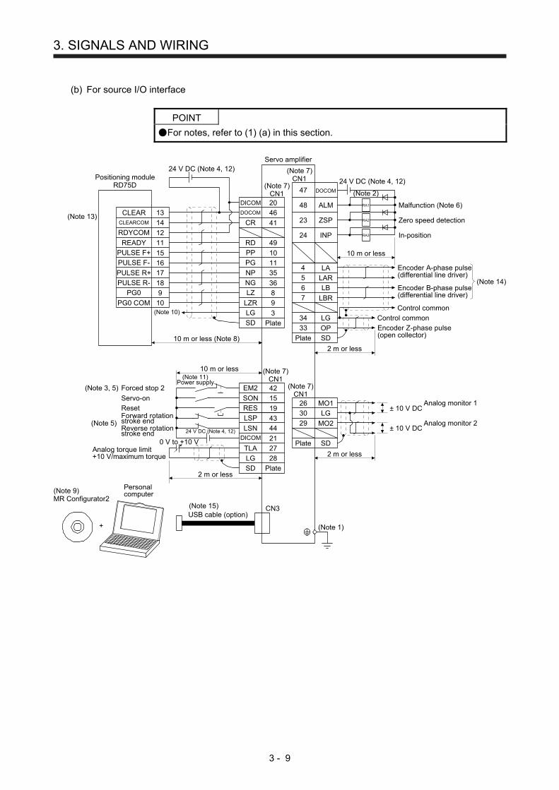
3. SIGNALS AND WIRING
3 - 9
(b) For source I/O interface
POINT
For notes, refer to (1) (a) in this section.
2 m or less
26 MO1
30 LG
29 MO2
± 10 V DC
± 10 V DC
SD
Servo amplifier
(Note 2)
Malfunction (Note 6)
Zero speed detection
47 DOCOM
48 ALM
23 ZSP
24 INP
4 LA5 LAR
6 LB
7 LBR
34 LG
33 OP
SD
10 m or less
2 m or less
(Note 7)CN1
LG
DICOM
10 m or less (Note 8)
41
20
46
49
10
11
35
9
3
36
CLEARCOM
12
15
16
14
13
11
CLEAR
RDYCOM
READY
PULSE F+
PULSE F-
PG0
PG0 COM
PULSE R+
PULSE R- 18
10
17
9
DOCOM
CR
RD
PP
PG
NP
NG
LZ
LZR
8
(Note 10)
(Note 13)
(Note 7)CN1
Positioning moduleRD75D
24 V DC (Note 4, 12)
In-position
SD
RA1
RA2
RA3
24 V DC (Note 4, 12)
24 V DC (Note 4, 12)
(Note 1)
2 m or less
10 m or less
42
15
19
43
44
21
27
SD
EM2
SON
RES
LSP
LSNDICOM
TLA
LG 28
(Note 7)CN1
+
(Note 9)MR Configurator2
(Note 7)CN1
CN3
(Note 11)Power supply
0 V to +10 V
Encoder A-phase pulse(differential line driver)
Encoder B-phase pulse(differential line driver)
Control common
Encoder Z-phase pulse(open collector)
Control common
Forced stop 2
Servo-on
ResetForward rotationstroke endReverse rotationstroke end
(Note 3, 5)
(Note 5)
Analog torque limit+10 V/maximum torque
Plate
Plate
Plate
Plate
USB cable (option)
Personalcomputer
Analog monitor 1
Analog monitor 2
(Note 15)
(Note 14)

3. SIGNALS AND WIRING
3 - 10
(2) When you use a positioning module FX3U-_ _MT/ES (For sink I/O interface)
Servo amplifier
(Note 1)
2 m or less
10 m or less
42
15
19
43
44
21
27
SD
EM2
SON
RES
LSP
LSNDICOM
TLA
LG 28
(Note 7)CN1
+
(Note 9)MR Configurator2
CN3
(Note 10)Power supply
(Note 2)
(Note 7)CN1
47 DOCOM
48 ALM
23 ZSP
4 LA
5 LAR
6 LB
7 LBR
34 LG
SD
8 LZ
9 LZR
RA1
RA2
10 m or less
(Note 7)CN1
COM3
X _ _ _
X000RD
3
49
33
10
12
35
41
20
L
N
COM2
Y000
COM1
Y004
Y010
OP
LG
PP
OPC
NP
DICOM
DOCOM
CR
46
Programmable controllerFX3U-_ _MT/ES (Note 11)
S/S
24 V
0 V
Programmablecontrollerpower supply
2 m or less (Note 8)
24 V DC(Note 4)
24 V DC (Note 4)
24 V DC (Note 4)
(Note 12)
(Note 13)
(Note 14)
X _ _ _ INP 24
SD
2 m or less
26 MO1
30 LG
29 MO2
± 10 V DC
± 10 V DC
SD
(Note 7)CN1
0 V to +10 V
Malfunction (Note 6)
Zero speed detection
Encoder A-phase pulse(differential line driver)
Encoder Z-phase pulse(differential line driver)
Encoder B-phase pulse(differential line driver)
Control common
Plate
Plate
Plate
Plate
Forced stop 2
Servo-on
ResetForward rotationstroke endReverse rotationstroke end
(Note 3, 5)
(Note 5)
Analog torque limit+10 V/maximum torque
USB cable (option)
Personalcomputer
Analog monitor 1
Analog monitor 2
(Note 16)
(Note 15)

3. SIGNALS AND WIRING
3 - 11
Note 1. To prevent an electric shock, always connect the protective earth (PE) terminal (marked ) of the servo amplifier to the
protective earth (PE) of the cabinet.
2. Connect the diode in the correct direction. If it is connected reversely, the servo amplifier will malfunction and will not output
signals, disabling EM2 (Forced stop 2) and other protective circuits.
3. The forced stop switch (normally closed contact) must be installed.
4. Supply 24 V DC ± 10% to interfaces from outside. The total current capacity is up to 300 mA. 300 mA is the value applicable
when all I/O signals are used. The current capacity can be decreased by reducing the number of I/O points. Refer to section
3.9.2 (1) that gives the current value necessary for the interface. The illustration of the 24 V DC power supply is divided
between input signal and output signal for convenience. However, they can be configured by one.
5. When starting operation, always turn on EM2 (Forced stop 2), LSP (Forward rotation stroke end) and LSN (Reverse rotation
stroke end) (normally closed contact).
6. ALM (Malfunction) turns on in normal alarm-free condition (normally closed contact). When this signal is switched off (at
occurrence of an alarm), the output of the programmable controller should be stopped by the sequence program.
7. The pins with the same signal name are connected in the servo amplifier.
8. Connect them within 2 m because of open-collector type.
9. Use SW1DNC-MRC2-_. (Refer to section 11.4.)
10. Configure a circuit to turn off EM2 when the power is turned off to prevent an unexpected restart of the servo amplifier.
11. Select the number of I/O points of the programmable controller depending on your system.
12. It will be COM0 for FX3U-16MT/ES.
13. It will be COM4 for FX3U-16MT/ES.
14. Select it within X000 to X007.
15. When a command cable for connection with the controller side malfunctions due to disconnection or noise, a position
mismatch can occur. To avoid position mismatch, it is recommended that Encoder A-phase pulse and Encoder B-phase pulse
be checked.
16. The USB communication function and RS-422/RS-485 communication function are mutually exclusive. They cannot be used
together.

3. SIGNALS AND WIRING
3 - 12
3.2.2 Speed control mode
(1) For sink I/O interface
(Note 10)Power supply
(Note 1)
(Note 2)
(Note 7)CN1
(Note 7)CN1
Servo amplifier
(Note 7)CN1
47 DOCOM
46 DOCOM
48 ALM
23 ZSP
24 SA
49 RD
4 LA
5 LAR
6 LB
7 LBR
34 LG
33 OP
SD
2 m or less
8 LZ
9 LZR20DICOM
21DICOM
10 m or less
2
2 m or less
28
27
VC
SD
TLA
LG
+
CN3
Analog speed command±10 V/rated speed
(Note 8) Analog torque limit+10 V/maximum torque
(Note 9)MR Configurator2
RA1
RA2
RA3
RA4
24 V DC (Note 4)
24 V DC (Note 4)
42
15
19
41
43
44
EM2
SON
ST1
ST2
LSP
LSN
Forward rotation start
Reverse rotation start
Encoder Z-phase pulse(open collector)
Speed reached
Ready
10 m or less
2 m or less
26 MO1
30 LG29 MO2
± 10 V DC
± 10 V DC
SD
-10 V to +10 V
0 V to +10 V
Forced stop 2
Servo-on
Forward rotationstroke endReverse rotationstroke end
(Note 3, 5)
(Note 5)
Plate
Plate
Plate
USB cable (option)
Personalcomputer
Analog monitor 1
Analog monitor 2
Malfunction (Note 6)
Zero speed detection
Encoder A-phase pulse(differential line driver)
Encoder Z-phase pulse(differential line driver)
Encoder B-phase pulse(differential line driver)
Control common
(Note 12)
Note 1. To prevent an electric shock, always connect the protective earth (PE) terminal (marked ) of the servo amplifier to the
protective earth (PE) of the cabinet.
2. Connect the diode in the correct direction. If it is connected reversely, the servo amplifier will malfunction and will not output
signals, disabling EM2 (Forced stop 2) and other protective circuits.
3. The forced stop switch (normally closed contact) must be installed.
4. Supply 24 V DC ± 10% to interfaces from outside. The total current capacity is up to 300 mA. 300 mA is the value applicable
when all I/O signals are used. The current capacity can be decreased by reducing the number of I/O points. Refer to section
3.9.2 (1) that gives the current value necessary for the interface. The illustration of the 24 V DC power supply is divided
between input signal and output signal for convenience. However, they can be configured by one.
5. When starting operation, always turn on EM2 (Forced stop 2), LSP (Forward rotation stroke end) and LSN (Reverse rotation
stroke end) (normally closed contact).
6. ALM (Malfunction) turns on in normal alarm-free condition (normally closed contact).
7. The pins with the same signal name are connected in the servo amplifier.
8. TLA will be available when TL (External torque limit selection) is enabled with [Pr. PD03], [Pr. PD11], [Pr. PD13], [Pr. PD17],
and [Pr. PD19]. (Refer to section 3.6.1 (5).)
9. Use SW1DNC-MRC2-_. (Refer to section 11.4.)
10. Configure a circuit to turn off EM2 when the power is turned off to prevent an unexpected restart of the servo amplifier.
11. Plus and minus of the power of source interface are the opposite of those of sink interface.
12. The USB communication function and RS-422/RS-485 communication function are mutually exclusive. They cannot be used
together.

3. SIGNALS AND WIRING
3 - 13
(2) For source I/O interface
POINT
For notes, refer to (1) in this section.
(Note 1)
(Note 2)
(Note 7)CN1
(Note 7)CN1
(Note 7)CN1
47 DOCOM
46 DOCOM
48 ALM
23 ZSP
24 SA
49 RD
4 LA
5 LAR
6 LB
7 LBR
34 LG
33 OP
SD
2 m or less
8 LZ
9 LZR
20DICOM
21DICOM
2
2 m or less
28
27
VC
SD
TLA
LG
+
CN3
(Note 9)MR Configurator2
RA1
RA2
RA3
RA4
42
15
19
41
43
44
EM2
SON
ST1
ST2
LSP
LSN10 m or less
2 m or less
26 MO1
30 LG29 MO2
± 10 V DC
± 10 V DC
SD
24 V DC (Note 4, 11)
10 m or less
24 V DC (Note 4, 11)
-10 V to +10 V
0 V to +10 V
Forward rotation start
Reverse rotation start
Forced stop 2
Servo-on
Forward rotationstroke endReverse rotationstroke end
(Note 3, 5)
(Note 5)
Servo amplifier
Plate
Plate
Plate
(Note 10)Power supply
Speed reached
Ready
Malfunction (Note 6)
Zero speed detection
Encoder A-phase pulse(differential line driver)
Encoder Z-phase pulse(differential line driver)
Encoder B-phase pulse(differential line driver)
Control common
Encoder Z-phase pulse(open collector)
Analog monitor 1
Analog monitor 2
USB cable (option)
Personalcomputer
Analog speed command±10 V/rated speed
(Note 8) Analog torque limit+10 V/maximum torque
(Note 12)
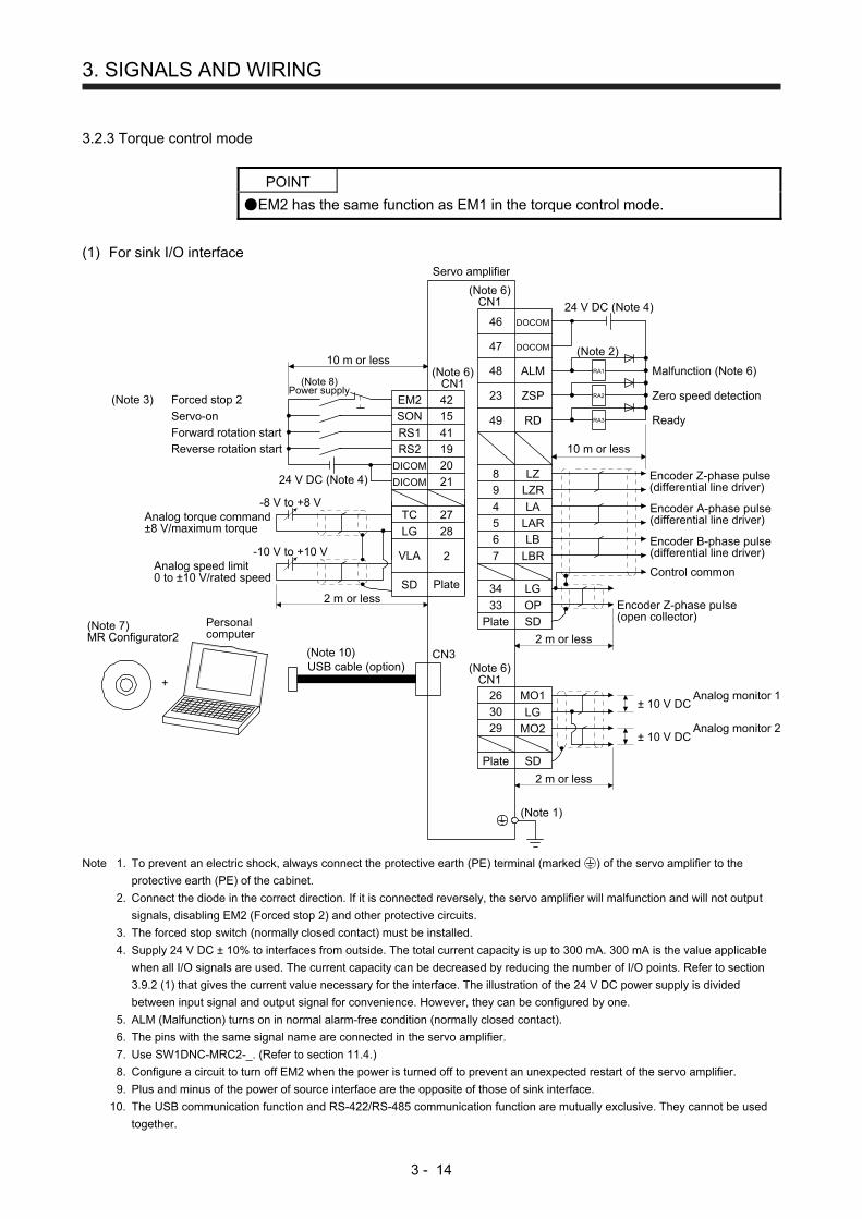
3. SIGNALS AND WIRING
3 - 14
3.2.3 Torque control mode
POINT
EM2 has the same function as EM1 in the torque control mode.
(1) For sink I/O interface Servo amplifier
(Note 6)CN1
(Note 1)
9
(Note 2)47 DOCOM
46 DOCOM
48 ALM
23 ZSP
4 LA
5 LAR
6 LB
7 LBR
34 LG
33 OP
SD
10 m or less
2 m or less
(Note 6)CN1
49 RD
8 LZ
LZR
(Note 6)CN1
20DICOM
21DICOM
+
CN3
27
2 m or less
28
2
TC
SD
VLA
LGAnalog torque command±8 V/maximum torque
Analog speed limit0 to ±10 V/rated speed
(Note 7)MR Configurator2
42
15
19
41
EM2
SON
RS1
RS2
RA1
RA2
RA3
2 m or less
26 MO1
30 LG29 MO2
± 10 V DC
± 10 V DC
SD
24 V DC (Note 4)
10 m or less
24 V DC (Note 4)
-8 V to +8 V
-10 V to +10 V
Forward rotation start
Reverse rotation start
Forced stop 2
Servo-on
(Note 3)
(Note 8)Power supply
Plate
Plate
Plate
Ready
Malfunction (Note 6)
Zero speed detection
Encoder A-phase pulse(differential line driver)
Encoder Z-phase pulse(differential line driver)
Encoder B-phase pulse(differential line driver)
Control common
Encoder Z-phase pulse(open collector)
Analog monitor 1
Analog monitor 2
USB cable (option)
Personalcomputer
(Note 10)
Note 1. To prevent an electric shock, always connect the protective earth (PE) terminal (marked ) of the servo amplifier to the
protective earth (PE) of the cabinet.
2. Connect the diode in the correct direction. If it is connected reversely, the servo amplifier will malfunction and will not output
signals, disabling EM2 (Forced stop 2) and other protective circuits.
3. The forced stop switch (normally closed contact) must be installed.
4. Supply 24 V DC ± 10% to interfaces from outside. The total current capacity is up to 300 mA. 300 mA is the value applicable
when all I/O signals are used. The current capacity can be decreased by reducing the number of I/O points. Refer to section
3.9.2 (1) that gives the current value necessary for the interface. The illustration of the 24 V DC power supply is divided
between input signal and output signal for convenience. However, they can be configured by one.
5. ALM (Malfunction) turns on in normal alarm-free condition (normally closed contact).
6. The pins with the same signal name are connected in the servo amplifier.
7. Use SW1DNC-MRC2-_. (Refer to section 11.4.)
8. Configure a circuit to turn off EM2 when the power is turned off to prevent an unexpected restart of the servo amplifier.
9. Plus and minus of the power of source interface are the opposite of those of sink interface.
10. The USB communication function and RS-422/RS-485 communication function are mutually exclusive. They cannot be used
together.
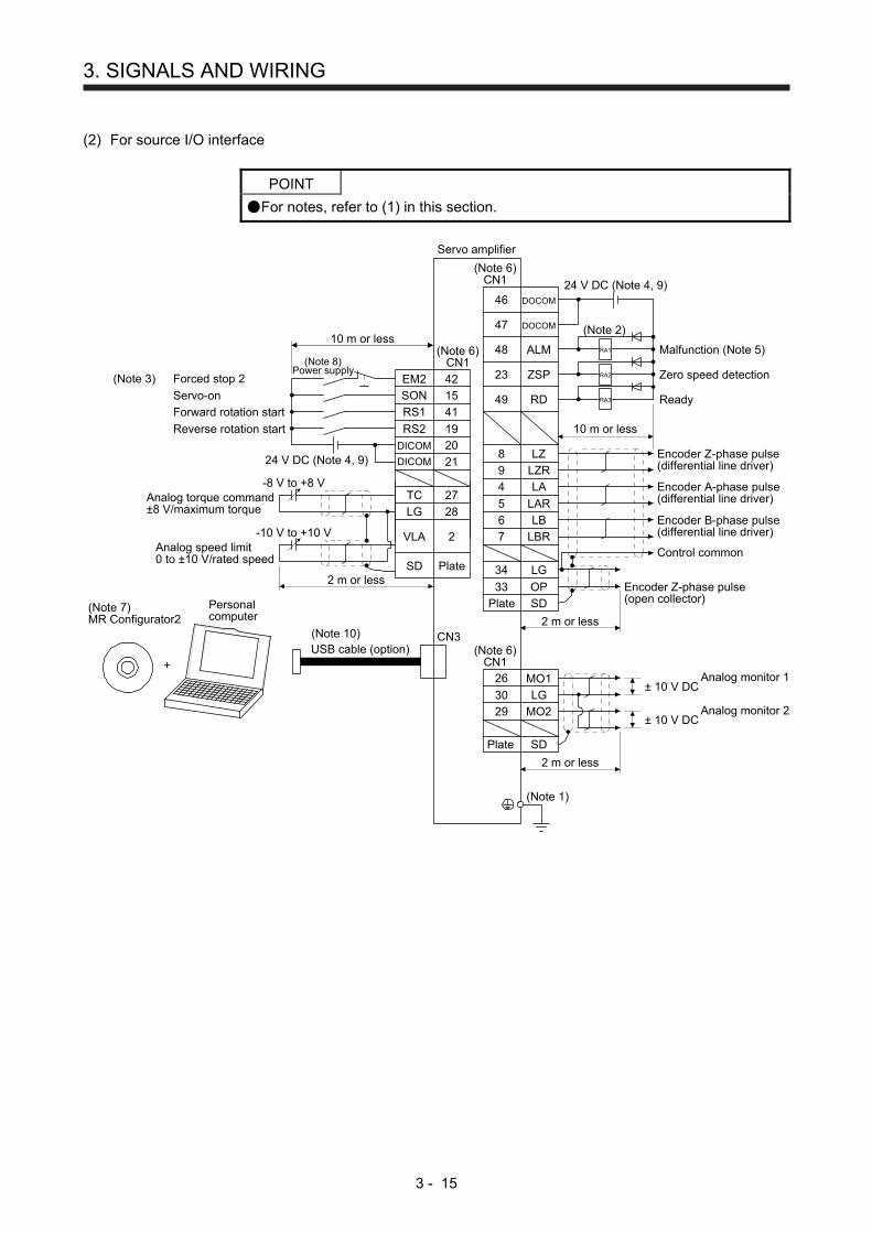
3. SIGNALS AND WIRING
3 - 15
(2) For source I/O interface
POINT
For notes, refer to (1) in this section.
-8 V to +8 V
-10 V to +10 V
24 V DC (Note 4, 9)
Servo amplifier
(Note 6)CN1
(Note 1)
9
(Note 2)47 DOCOM
DICOM
DICOM
46 DOCOM
48 ALM
23 ZSP
4 LA
5 LAR
6 LB
7 LBR
34 LG
33 OP
SD
10 m or less
2 m or less
(Note 6)CN1
49 RD
8 LZ
LZR
(Note 6)CN1
+
CN3
27
2 m or less
28
2
TC
SD
VLA
LG
(Note 7)MR Configurator2
42
15
41
19
20
21
EM2
SON
RS1
RS2
RA1
RA2
RA3
2 m or less
26 MO1
30 LG
29 MO2
± 10 V DC
± 10 V DC
SD
10 m or less
24 V DC (Note 4, 9)
Forward rotation start
Reverse rotation start
Forced stop 2
Servo-on
(Note 3)
(Note 8)Power supply
Plate
Plate
Plate
Ready
Malfunction (Note 5)
Zero speed detection
Encoder A-phase pulse(differential line driver)
Encoder Z-phase pulse(differential line driver)
Encoder B-phase pulse(differential line driver)
Control common
Encoder Z-phase pulse(open collector)
Analog monitor 1
Analog monitor 2
USB cable (option)
Personalcomputer
Analog torque command±8 V/maximum torque
Analog speed limit0 to ±10 V/rated speed
(Note 10)

3. SIGNALS AND WIRING
3 - 16
3.3 Explanation of power supply system
3.3.1 Signal explanations
POINT
For the layout of connector and terminal block, refer to chapter 9 DIMENSIONS.
Symbol Connection target
(application) Description
L1/L2/L3 Power supply
Supply the following power to L1, L2, and L3. For 1-phase 200 V AC to 240 V AC, connect the power supply to L1 and L3. Leave L2 open. When using 1-phase 200 V AC to 240 V AC for MR-JE-200A, connect the power supply to L1 and L2. Leave L3 open.
Servo amplifierPower supply
MR-JE-10A to MR-JE-100A
MR-JE-200A MR-JE-300A
3-phase 200 V AC to 240 V AC, 50 Hz/60 Hz
L1/L2/L3
1-phase 200 V AC to 240 V AC, 50 Hz/60 Hz
L1/L3 L1/L2
P+/C/D Regenerative
option
1) MR-JE-100A or less MR-JE-10A to MR-JE-100A do not have D. When using a servo amplifier built-in regenerative resistor, connect P+ and C. (factory-wired) MR-JE-10A and MR-JE-20A do not have a built-in regenerative resistor. When using a regenerative option, disconnect wires of P+ and C for the built-in regenerative resistor. And then connect wires of the regenerative option to P+ and C.
2) MR-JE-200A or more When using a servo amplifier built-in regenerative resistor, connect P+ and D. (factory-wired) When using a regenerative option, disconnect P+ and D, and connect the regenerative option to P+ and C.
Refer to section 11.2 for details.
U/V/W Servo motor power output
Connect them to the servo motor power supply (U, V, and W). Connect the servo amplifier power output (U, V, and W) to the servo motor power input (U, V, and W) directly. Do not let a magnetic contactor, etc. intervene. Otherwise, it may cause a malfunction.
N- This is for manufacturer adjustment. Leave this open. MR-JE-10A to MR-JE-100A do not have N-.
Protective earth
(PE) Connect it to the grounding terminal of the servo motor and to the protective earth (PE) of the cabinet for grounding.
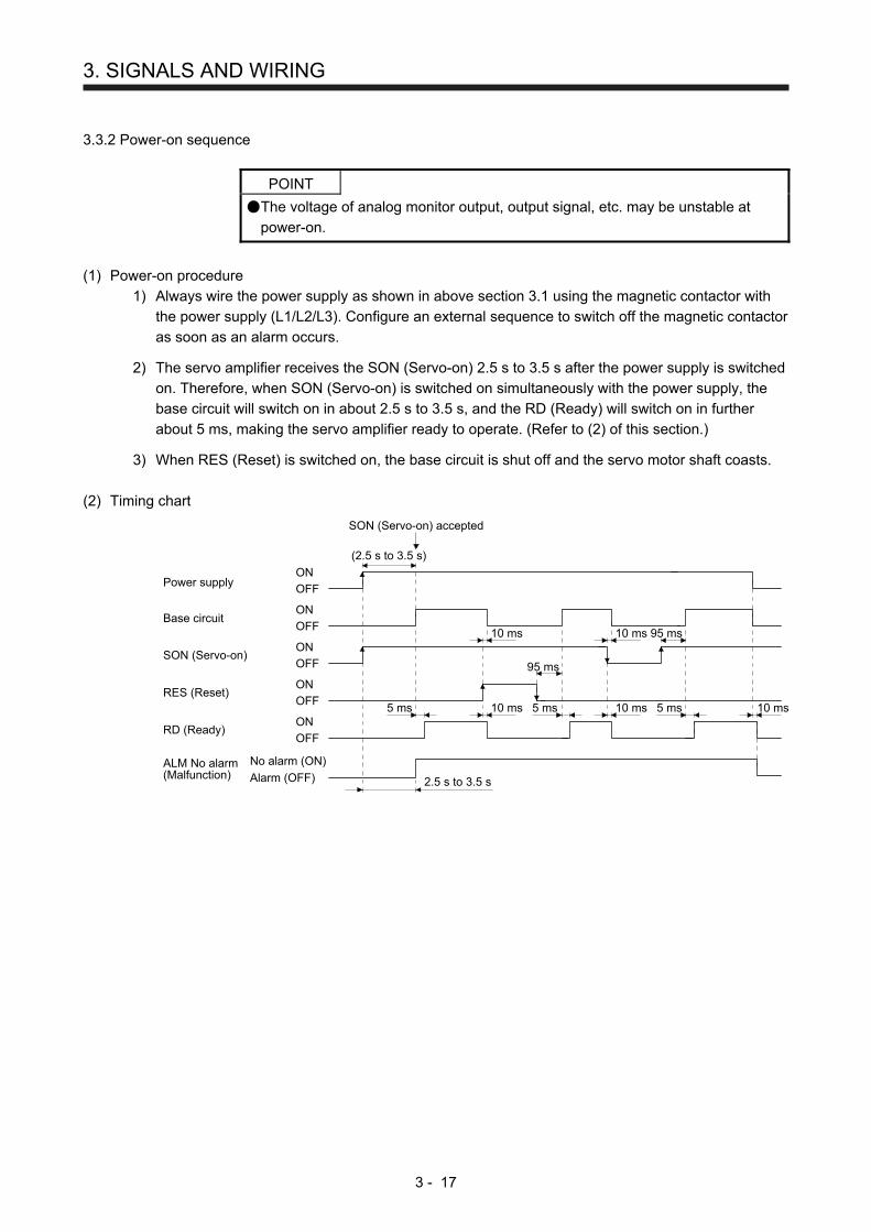
3. SIGNALS AND WIRING
3 - 17
3.3.2 Power-on sequence
POINT
The voltage of analog monitor output, output signal, etc. may be unstable at
power-on.
(1) Power-on procedure
1) Always wire the power supply as shown in above section 3.1 using the magnetic contactor with
the power supply (L1/L2/L3). Configure an external sequence to switch off the magnetic contactor
as soon as an alarm occurs.
2) The servo amplifier receives the SON (Servo-on) 2.5 s to 3.5 s after the power supply is switched
on. Therefore, when SON (Servo-on) is switched on simultaneously with the power supply, the
base circuit will switch on in about 2.5 s to 3.5 s, and the RD (Ready) will switch on in further
about 5 ms, making the servo amplifier ready to operate. (Refer to (2) of this section.)
3) When RES (Reset) is switched on, the base circuit is shut off and the servo motor shaft coasts.
(2) Timing chart
95 ms
95 ms
RD (Ready)
RES (Reset)
SON (Servo-on)OFF
ON
OFF
ON
ON
OFF
Base circuitOFF
ON
Power supplyOFF
ON
10 ms5 ms
10 ms
10 ms5 ms
10 ms
5 ms 10 ms
(2.5 s to 3.5 s)
SON (Servo-on) accepted
Alarm (OFF)
No alarm (ON)ALM No alarm(Malfunction)
2.5 s to 3.5 s
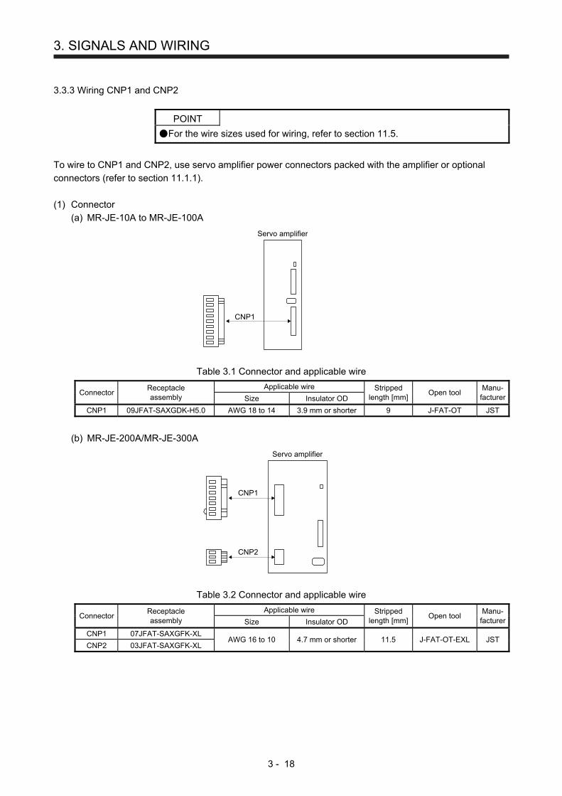
3. SIGNALS AND WIRING
3 - 18
3.3.3 Wiring CNP1 and CNP2
POINT
For the wire sizes used for wiring, refer to section 11.5.
To wire to CNP1 and CNP2, use servo amplifier power connectors packed with the amplifier or optional
connectors (refer to section 11.1.1).
(1) Connector
(a) MR-JE-10A to MR-JE-100A
CNP1
Servo amplifier
Table 3.1 Connector and applicable wire
Connector Receptacle assembly
Applicable wire Stripped length [mm]
Open tool Manu-
facturerSize Insulator OD
CNP1 09JFAT-SAXGDK-H5.0 AWG 18 to 14 3.9 mm or shorter 9 J-FAT-OT JST
(b) MR-JE-200A/MR-JE-300A
CNP1
CNP2
Servo amplifier
Table 3.2 Connector and applicable wire
Connector Receptacle assembly
Applicable wire Stripped length [mm]
Open tool Manu-
facturerSize Insulator OD
CNP1 07JFAT-SAXGFK-XL AWG 16 to 10 4.7 mm or shorter 11.5 J-FAT-OT-EXL JST
CNP2 03JFAT-SAXGFK-XL

3. SIGNALS AND WIRING
3 - 19
(2) Cable connection procedure
(a) Fabrication on cable insulator
Refer to table 3.1 and 3.2 for stripped length of cable insulator. The appropriate stripped length of
cables depends on their type, etc. Set the length considering their status.
Insulator Core
Stripped length
Twist strands lightly and straighten them as follows.
Loose and bent strands Twist and straightenthe strands.
You can also use a ferrule to connect with the connectors. When you use a ferrule, use the following
ferrules and crimp terminal.
Servo amplifier Wire size Ferrule model (Phoenix Contact) Crimp terminal
(Phoenix Contact) For one For two
MR-JE-10A to MR-JE-100A
AWG 16 AI1.5-10BK AI-TWIN2×1.5-10BK
CRIMPFOX-ZA3
AWG 14 AI2.5-10BU
MR-JE-200A to MR-JE-300A
AWG 16 AI1.5-10BK AI-TWIN2×1.5-10BK
AWG 14 AI2.5-10BU AI-TWIN2×2.5-10BU
AWG 12 AI4-10GY
(b) Inserting wire
Insert the open tool as follows and push down it to open the spring. While the open tool is pushed
down, insert the stripped wire into the wire insertion hole. Check the insertion depth so that the wire
insulator does not get caught by the spring.
Release the open tool to fix the wire. Pull the wire lightly to confirm that the wire is surely connected.
The following shows a connection example of the CNP2 connector for 2 kW and 3 kW.
1) Push down the open tool.
3) Release the open tool to fix the wire.
2) Insert the wire.
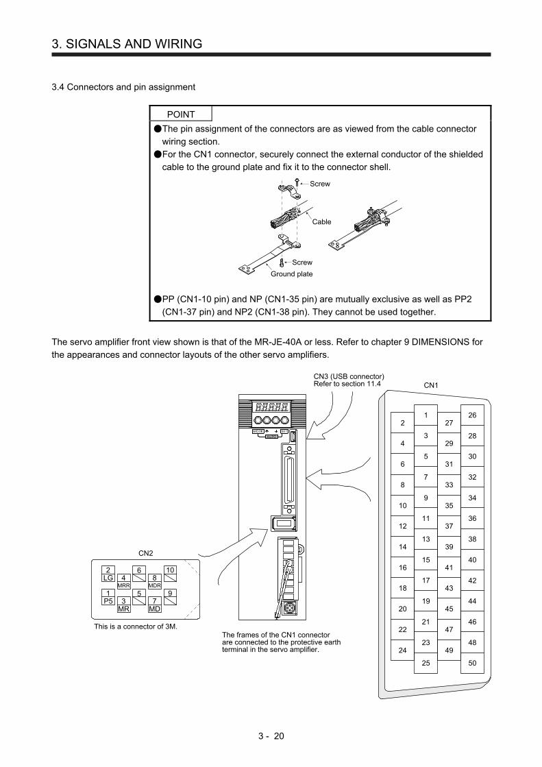
3. SIGNALS AND WIRING
3 - 20
3.4 Connectors and pin assignment
POINT
The pin assignment of the connectors are as viewed from the cable connector
wiring section.
For the CN1 connector, securely connect the external conductor of the shielded
cable to the ground plate and fix it to the connector shell.
Screw
Screw
Ground plate
Cable
PP (CN1-10 pin) and NP (CN1-35 pin) are mutually exclusive as well as PP2
(CN1-37 pin) and NP2 (CN1-38 pin). They cannot be used together.
The servo amplifier front view shown is that of the MR-JE-40A or less. Refer to chapter 9 DIMENSIONS for
the appearances and connector layouts of the other servo amplifiers.
CN1
The frames of the CN1 connectorare connected to the protective earthterminal in the servo amplifier.
CN3 (USB connector)Refer to section 11.4
This is a connector of 3M.
4MRR
2LG 8
6
1P5
5
10
3MR
79
CN2
MDR
MD
2
4
6
8
10
12
14
16
18
20
22
24
1
3
5
7
9
11
13
15
17
19
21
23
27
29
31
33
35
37
39
41
43
45
47
49
26
28
30
32
34
36
38
40
42
44
46
48
25 50

3. SIGNALS AND WIRING
3 - 21
The device assignment of CN1 connector pins changes depending on the control mode. For the pins
which are given parameters in the related parameter column, their devices will be changed using those
parameters.
Pin No. (Note 1)
I/O (Note 2) I/O signals in control modes
Related parameter P P/S S S/T T T/P
1
2 I -/VC VC VC/VLA VLA VLA/-
3 LG LG LG LG LG LG
4 O LA LA LA LA LA LA
5 O LAR LAR LAR LAR LAR LAR
6 O LB LB LB LB LB LB
7 O LBR LBR LBR LBR LBR LBR
8 O LZ LZ LZ LZ LZ LZ
9 O LZR LZR LZR LZR LZR LZR
10 I PP PP/- (Note 5) (Note 5) (Note 5) -/PP Pr. PD43/Pr. PD44 (Note 4)
11 I PG PG/- -/PG
12 OPC OPC/- -/OPC
13 O SDP SDP SDP SDP SDP SDP
14 O SDN SDN SDN SDN SDN SDN
15 I SON SON SON SON SON SON Pr. PD03/Pr. PD04
16
17
18
19 I RES RES/ST1 ST1 ST1/RS2 RS2 RS2/RES Pr. PD11/Pr. PD12
20 DICOM DICOM DICOM DICOM DICOM DICOM
21 DICOM DICOM DICOM DICOM DICOM DICOM
22
23 O ZSP ZSP ZSP ZSP ZSP ZSP Pr. PD24
24 O INP INP/SA SA SA/- -/INP Pr. PD25
25
26 O MO1 MO1 MO1 MO1 MO1 MO1 Pr. PC14
27 I TLA (Note 3)
TLA (Note 3)
TLA (Note 3) TLA/TC
TC (Note 3) TC/TLA
28 LG LG LG LG LG LG
29 O MO2 MO2 MO2 MO2 MO2 MO2 Pr. PC15
30 LG LG LG LG LG LG
31 I TRE TRE TRE TRE TRE TRE
32
33 O OP OP OP OP OP OP
34 LG LG LG LG LG LG
35 I NP NP/- (Note 5) (Note 5) (Note 5) -/NP Pr. PD43/Pr. PD44 (Note 4)
36 I NG NG/- -/NG
37 (Note 7)
I PP2 PP2/- (Note 6) (Note 6) (Note 6) -/PP2 Pr. PD43/Pr. PD44 (Note 4)
38 (Note 7)
I NP2 NP2/- (Note 6) (Note 6) (Note 6) -/NP2 Pr. PD45/Pr. PD46 (Note 4)
39 I RDP RDP RDP RDP RDP RDP
40 I RDN RDN RDN RDN RDN RDN
41 I CR CR/ST2 ST2 ST2/RS1 RS1 RS1/CR Pr. PD13/Pr. PD14
42 I EM2 EM2 EM2 EM2 EM2 EM2
43 I LSP LSP LSP LSP/- -/LSP Pr. PD17/Pr. PD18
44 I LSN LSN LSN LSN/- -/LSN Pr. PD19/Pr. PD20
45

3. SIGNALS AND WIRING
3 - 22
Pin No. (Note 1)
I/O (Note 2) I/O signals in control modes
Related parameter P P/S S S/T T T/P
46 DOCOM DOCOM DOCOM DOCOM DOCOM DOCOM
47 DOCOM DOCOM DOCOM DOCOM DOCOM DOCOM
48 O ALM ALM ALM ALM ALM ALM
49 O RD RD RD RD RD RD Pr. PD28
50
Note 1. I: input signal, O: output signal
2. P: position control mode, S: speed control mode, T: torque control mode, P/S: position/speed control switching
mode, S/T: speed/torque control switching mode, T/P: torque/position control switching mode
3. TLA will be available when TL (External torque limit selection) is enabled with [Pr. PD03], [Pr. PD11], [Pr. PD13],
[Pr. PD17], and [Pr. PD19].
4. This is available with servo amplifiers with software version B7 or later.
5. This is used with sink interface. Input devices are not assigned by default. Assign the input devices with [Pr.
PD43] to [Pr. PD46] as necessary. In addition, supply + of 24 DC V to the CN1-12 pin of OPC (power input for
open-collector sink interface). This is available with servo amplifiers with software version B7 or later.
6. This is used with source interface. Input signals are not assigned by default. Assign the input devices with [Pr.
PD43] to [Pr. PD46] as necessary.
7. These pins are available with servo amplifiers having software version B7 or later, and manufactured in May,
2015 or later.
3. SIGNALS AND WIRING
3 - 23
3.5 Signal (device) explanations
For the I/O interfaces (symbols in I/O division column in the table), refer to section 3.9.2. In the control mode
field of the table
P: position control mode, S: speed control mode, T: torque control mode Torque control mode
: devices used with initial setting status, : devices used by setting [Pr. PA04] and [Pr. PD03] to [Pr.
PD28]
The pin numbers in the connector pin No. column are those in the initial status.
(1) I/O device
(a) Input device
Device Symbol Connector
pin No. Function and application
I/O division
Control mode
P S T
Forced stop 2 EM2 CN1-42 Turn off EM2 (open between commons) to decelerate the servo motor to a stop with commands. Turn EM2 on (short between commons) in the forced stop state to reset that state. The following shows the setting of [Pr. PA04].
DI-1
[Pr. PA04] setting
EM2/EM1Deceleration method
EM2 or EM1 is off Alarm occurred
0 _ _ _ EM1
MBR (Electromagnetic brake interlock) turns off without the forced stop deceleration.
MBR (Electromagnetic brake interlock) turns off without the forced stop deceleration.
2 _ _ _ EM2
MBR (Electromagnetic brake interlock) turns off after the forced stop deceleration.
MBR (Electromagnetic brake interlock) turns off after the forced stop deceleration.
EM2 and EM1 are mutually exclusive. EM2 has the same function as EM1 in the torque control mode.
Forced stop 1 EM1 (CN1-42) When using EM1, set [Pr. PA04] to "0 _ _ _" to enable EM1. Turn EM1 off (open between commons) to bring the motor to a forced stop state. The base circuit is shut off, the dynamic brake is operated and decelerate the servo motor to a stop. Turn EM1 on (short between commons) in the forced stop state to reset that state.
DI-1
Servo-on SON CN1-15 Turn SON on to power on the base circuit and make the servo amplifier ready to operate. (servo-on status) Turn it off to shut off the base circuit and coast the servo motor. Set "_ _ _ 4" in [Pr. PD01] to switch this signal on (keep terminals connected) automatically in the servo amplifier.
DI-1
Reset RES CN1-19 Turn on RES for more than 50 ms to reset the alarm. Some alarms cannot be deactivated by RES (Reset). Refer to section 8.1. Turning RES on in an alarm-free status shuts off the base circuit. The base circuit is not shut off when " _ _ 1 _ " is set in [Pr. PD30]. This device is not designed to make a stop. Do not turn it on during operation.
DI-1

3. SIGNALS AND WIRING
3 - 24
Device Symbol Connector
pin No. Function and application
I/O division
Control mode
P S T
Forward rotation stroke end
LSP CN1-43 To start operation, turn on LSP and LSN. Turn it off to bring the motor to a sudden stop and make it servo-locked. Setting [Pr. PD30] to " _ _ _ 1" will enable a slow stop.
DI-1
Reverse rotation stroke end
LSN CN1-44 (Note) Input device Operation
LSP LSN
CCW direction
CW direction
1 1
0 1
1 0
0 0
Note. 0: Off
1: On
Set [Pr. PD01] as indicated below to switch on the signals (keep terminals connected) automatically in the servo amplifier.
[Pr. PD01]
Status
LSP LSN
_ 4 _ _
Automatic on
_ 8 _ _
Automatic on
_ C _ _
Automatic on
Automatic on
When LSP or LSN turns off, [AL. 99 Stroke limit warning] occurs, and WNG (Warning) turns on. When using WNG, enable it by setting [Pr. PD24], [Pr. PD25] and [Pr. PD28].
External torque limit selection
TL Turning off TL will enable [Pr. PA11 Forward torque limit] and [Pr. PA12 Reverse torque limit], and turning on it will enable TLA (Analog torque limit). For details, refer to section 3.6.1 (5).
DI-1
Internal torque limit selection
TL1 To select [Pr. PC35 Internal torque limit 2], enable TL1 with [Pr. PD03] to [Pr. PD20]. For details, refer to section 3.6.1 (5).
DI-1
Forward rotation start
ST1 This is used to start the servo motor. The following shows the directions.
DI-1
(Note) Input device Servo motor starting direction
ST2 ST1
0 0 Stop (servo-lock)
0 1 CCW
1 0 CW
1 1 Stop (servo-lock)
Note. 0: Off
1: On
Reverse rotation start
ST2 If both ST1 and ST2 are switched on or off during operation, the servo motor will be decelerated to a stop according to the [Pr. PC02] setting and servo-locked. When " _ _ _1" is set in [Pr. PC23], the servo motor is not servo-locked after deceleration to a stop.

3. SIGNALS AND WIRING
3 - 25
Device Symbol Connector
pin No. Function and application
I/O division
Control mode
P S T
Forward rotation selection
RS1 Select a servo motor torque generation directions. The following shows the torque generation directions.
DI-1
(Note) Input device Torque generation direction
RS2 RS1
0 0 Torque is not generated.
Reverse rotation selection
RS2 0 1
Forward rotation in power running mode/reverse rotation
in regenerative mode
1 0
Reverse rotation in power running mode/forward rotation
in regenerative mode
1 1 Torque is not generated.
Note. 0: Off
1: On
Speed selection 1
SP1 1. For speed control mode Select the command speed for operation.
DI-1
Speed selection 2
SP2 (Note) Input device Speed command
DI-1
SP3 SP2 SP1
Speed selection 3
SP3 0 0 0 VC (Analog speed command) DI-1
0 0 1
Pr. PC05 Internal speed command 1
0 1 0
Pr. PC06 Internal speed command 2
0 1 1
Pr. PC07 Internal speed command 3
1 0 0
Pr. PC08 Internal speed command 4
1 0 1
Pr. PC09 Internal speed command 5
1 1 0
Pr. PC10 Internal speed command 6
1 1 1
Pr. PC11 Internal speed command 7
Note. 0: Off
1: On
2. For the torque control mode Select the limited speed for operation.
(Note) Input device Speed limit
SP3 SP2 SP1
0 0 0 VLA (Analog speed limit)
0 0 1 Pr. PC05 Internal speed limit 1
0 1 0 Pr. PC06 Internal speed limit 2
0 1 1 Pr. PC07 Internal speed limit 3
1 0 0 Pr. PC08 Internal speed limit 4
1 0 1 Pr. PC09 Internal speed limit 5
1 1 0 Pr. PC10 Internal speed limit 6
1 1 1 Pr. PC11 Internal speed limit 7
Note. 0: Off
1: On

3. SIGNALS AND WIRING
3 - 26
Device Symbol Connector
pin No. Function and application
I/O division
Control mode
P S T
Proportion control
PC Turn PC on to switch the speed amplifier from the proportional integral type to the proportional type. If the servo motor at a stop is rotated even one pulse due to any external factor, it generates torque to compensate for a position shift. When the servo motor shaft is to be locked mechanically after positioning completion (stop), switching on the PC (Proportion control) upon positioning completion will suppress the unnecessary torque generated to compensate for a position shift. When the shaft is to be locked for a long time, switch on the PC (Proportion control) and TL (External torque limit selection) at the same time to make the torque less than the rated by TLA (Analog torque limit).
DI-1
Clear CR CN1-41 Turn CR on to clear the position control counter droop pulse on its leading edge. The pulse width should be 10 ms or longer. The delay amount set in [Pr. PB03 Position command acceleration/deceleration time constant] is also cleared. When " _ _ _1 " is set to [Pr. PD32], the pulses are always cleared while CR is on.
DI-1
Electronic gear selection 1
CM1 The combination of CM1 and CM2 enables you to select four different electronic gear numerators set in the parameters.
DI-1
(Note) Input device Electronic gear numerator
CM2 CM1
0 0 Pr. PA06
Electronic gear selection 2
CM2 0 1 Pr. PC32 DI-1
1 0 Pr. PC33
1 1 Pr. PC34
Note. 0: Off
1: On
Gain switching CDP Turn on CDP to use the values of [Pr. PB29] to [Pr. PB36] and [Pr. PB56] to [Pr. PB60] as the load to motor inertia ratio and gain values.
DI-1

3. SIGNALS AND WIRING
3 - 27
Device Symbol Connector
pin No. Function and application
I/O division
Control mode
P S T
Control switching LOP «Position/speed control switching mode» This is used to select the control mode in the position/speed control switching mode.
DI-1 Refer to Function and application.
(Note) LOP
Control mode
0 Position
1 Speed
Note. 0: Off
1: On
«Speed/torque control switch mode» This is used to select the control mode in the speed/torque control switching mode.
(Note) LOP
Control mode
0 Speed
1 Torque
Note. 0: Off
1: On
«Torque/position control switch mode» This is used to select the control mode in the torque/position control switching mode.
(Note) LOP
Control mode
0 Torque
1 Position
Note. 0: Off
1: On
Second acceleration/ deceleration selection
STAB2 The device allows selection of the acceleration/deceleration time constants at servo motor rotation in the speed control mode or torque control mode. The s-pattern acceleration/deceleration time constant is always uniform.
DI-1
(Note) STAB2
Acceleration/deceleration time constant
0 Pr. PC01 Acceleration time constant
Pr. PC02 Deceleration time constant
1 Pr. PC30 Acceleration time constant 2
Pr. PC31 Deceleration time constant 2
Note. 0: Off
1: On
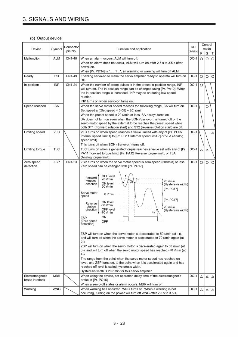
3. SIGNALS AND WIRING
3 - 28
(b) Output device
Device Symbol Connector
pin No. Function and application
I/O division
Control mode
P S T
Malfunction ALM CN1-48 When an alarm occurs, ALM will turn off. When an alarm does not occur, ALM will turn on after 2.5 s to 3.5 s after power-on. When [Pr. PD34] is "_ _ 1 _", an alarming or warning will turn off ALM.
DO-1
Ready RD CN1-49 Enabling servo-on to make the servo amplifier ready to operate will turn on RD.
DO-1
In-position INP CN1-24 When the number of droop pulses is in the preset in-position range, INP will turn on. The in-position range can be changed using [Pr. PA10]. When the in-position range is increased, INP may be on during low-speed rotation. INP turns on when servo-on turns on.
DO-1
Speed reached SA When the servo motor speed reaches the following range, SA will turn on. Set speed ± ((Set speed × 0.05) + 20) r/min When the preset speed is 20 r/min or less, SA always turns on. SA does not turn on even when the SON (Servo-on) is turned off or the servo motor speed by the external force reaches the preset speed while both ST1 (Forward rotation start) and ST2 (reverse rotation start) are off.
DO-1
Limiting speed VLC VLC turns on when speed reaches a value limited with any of [Pr. PC05 Internal speed limit 1] to [Pr. PC11 Internal speed limit 7] or VLA (Analog speed limit). This turns off when SON (Servo-on) turns off.
DO-1
Limiting torque TLC TLC turns on when a generated torque reaches a value set with any of [Pr. PA11 Forward torque limit], [Pr. PA12 Reverse torque limit], or TLA (Analog torque limit).
DO-1
Zero speed detection
ZSP CN1-23 ZSP turns on when the servo motor speed is zero speed (50r/min) or less. Zero speed can be changed with [Pr. PC17].
OFF
ON
Servo motorspeed
20 r/min(Hysteresis width)
[Pr. PC17]
20 r/min(Hysteresis width)
OFF level-70 r/min
ON level-50 r/min
ON level50 r/min
OFF level70 r/min
0 r/min
[Pr. PC17]
ZSP(Zero speeddetection)
1)3)
2)
4)
Forwardrotationdirection
Reverserotationdirection
ZSP will turn on when the servo motor is decelerated to 50 r/min (at 1)), and will turn off when the servo motor is accelerated to 70 r/min again (at 2)). ZSP will turn on when the servo motor is decelerated again to 50 r/min (at 3)), and will turn off when the servo motor speed has reached -70 r/min (at 4)). The range from the point when the servo motor speed has reached on level, and ZSP turns on, to the point when it is accelerated again and has reached off level is called hysteresis width. Hysteresis width is 20 r/min for this servo amplifier.
DO-1
Electromagnetic brake interlock
MBR When using the device, set operation delay time of the electromagnetic brake in [Pr. PC16]. When a servo-off status or alarm occurs, MBR will turn off.
DO-1
Warning WNG When warning has occurred, WNG turns on. When a warning is not occurring, turning on the power will turn off WNG after 2.5 s to 3.5 s.
DO-1
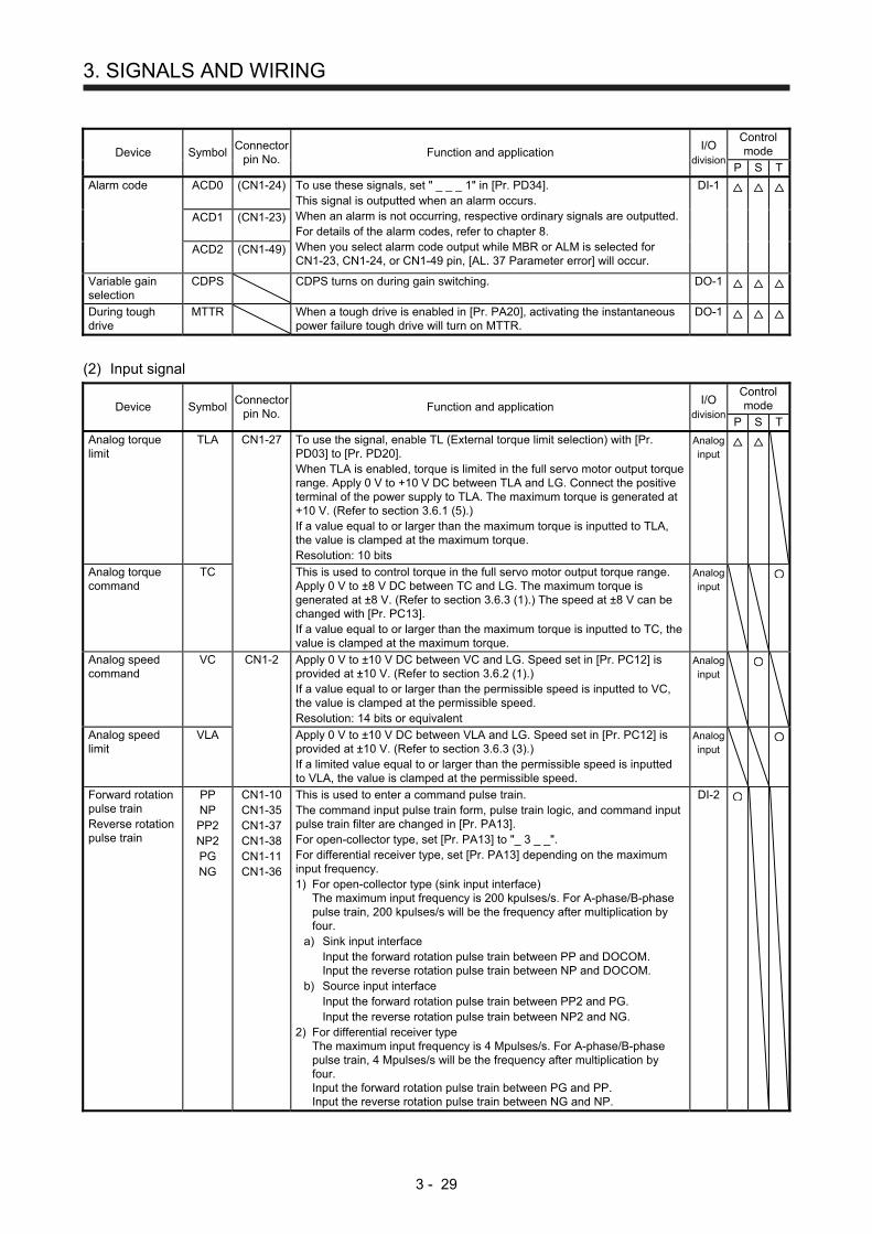
3. SIGNALS AND WIRING
3 - 29
Device Symbol Connector
pin No. Function and application
I/O division
Control mode
P S T
Alarm code ACD0 (CN1-24) To use these signals, set " _ _ _ 1" in [Pr. PD34]. This signal is outputted when an alarm occurs. When an alarm is not occurring, respective ordinary signals are outputted. For details of the alarm codes, refer to chapter 8. When you select alarm code output while MBR or ALM is selected for CN1-23, CN1-24, or CN1-49 pin, [AL. 37 Parameter error] will occur.
DI-1
ACD1 (CN1-23)
ACD2 (CN1-49)
Variable gain selection
CDPS CDPS turns on during gain switching. DO-1
During tough drive
MTTR When a tough drive is enabled in [Pr. PA20], activating the instantaneous power failure tough drive will turn on MTTR.
DO-1
(2) Input signal
Device Symbol Connector
pin No. Function and application
I/O division
Control mode
P S T
Analog torque limit
TLA CN1-27 To use the signal, enable TL (External torque limit selection) with [Pr. PD03] to [Pr. PD20]. When TLA is enabled, torque is limited in the full servo motor output torque range. Apply 0 V to +10 V DC between TLA and LG. Connect the positive terminal of the power supply to TLA. The maximum torque is generated at +10 V. (Refer to section 3.6.1 (5).) If a value equal to or larger than the maximum torque is inputted to TLA, the value is clamped at the maximum torque. Resolution: 10 bits
Analog input
Analog torque command
TC This is used to control torque in the full servo motor output torque range. Apply 0 V to ±8 V DC between TC and LG. The maximum torque is generated at ±8 V. (Refer to section 3.6.3 (1).) The speed at ±8 V can be changed with [Pr. PC13]. If a value equal to or larger than the maximum torque is inputted to TC, the value is clamped at the maximum torque.
Analog input
Analog speed command
VC CN1-2 Apply 0 V to ±10 V DC between VC and LG. Speed set in [Pr. PC12] is provided at ±10 V. (Refer to section 3.6.2 (1).) If a value equal to or larger than the permissible speed is inputted to VC, the value is clamped at the permissible speed. Resolution: 14 bits or equivalent
Analog input
Analog speed limit
VLA Apply 0 V to ±10 V DC between VLA and LG. Speed set in [Pr. PC12] is provided at ±10 V. (Refer to section 3.6.3 (3).) If a limited value equal to or larger than the permissible speed is inputted to VLA, the value is clamped at the permissible speed.
Analog input
Forward rotation pulse train Reverse rotation pulse train
PP NP PP2 NP2 PG NG
CN1-10 CN1-35 CN1-37 CN1-38 CN1-11 CN1-36
This is used to enter a command pulse train. The command input pulse train form, pulse train logic, and command input pulse train filter are changed in [Pr. PA13]. For open-collector type, set [Pr. PA13] to "_ 3 _ _". For differential receiver type, set [Pr. PA13] depending on the maximum input frequency. 1) For open-collector type (sink input interface)
The maximum input frequency is 200 kpulses/s. For A-phase/B-phase pulse train, 200 kpulses/s will be the frequency after multiplication by four.
a) Sink input interface Input the forward rotation pulse train between PP and DOCOM. Input the reverse rotation pulse train between NP and DOCOM.
b) Source input interface Input the forward rotation pulse train between PP2 and PG. Input the reverse rotation pulse train between NP2 and NG.
2) For differential receiver type The maximum input frequency is 4 Mpulses/s. For A-phase/B-phase pulse train, 4 Mpulses/s will be the frequency after multiplication by four. Input the forward rotation pulse train between PG and PP. Input the reverse rotation pulse train between NG and NP.
DI-2

3. SIGNALS AND WIRING
3 - 30
(3) Output signal
Device Symbol Connector
pin No. Function and application
I/O division
Control mode
P S T
Encoder A-phase pulse (differential line driver)
LA LAR
CN1-4 CN1-5
These devices output pulses of encoder output pulse set in [Pr. PA15] in the differential line driver type. In CCW rotation of the servo motor, the encoder B-phase pulse lags the encoder A-phase pulse by a phase angle of π/2. The relation between rotation direction and phase difference of the A-phase and B-phase pulses can be changed with [Pr. PC19].
DO-2
Encoder B-phase pulse (differential line driver)
LB LBR
CN1-6 CN1-7
Encoder Z-phase pulse (differential line driver)
LZ LZR
CN1-8 CN1-9
The encoder zero-point signal is outputted in the differential line driver type. One pulse is outputted per servo motor revolution. This turns on when the zero-point position is reached. (negative logic) The minimum pulse width is about 400 μs. For home position return using this pulse, set the creep speed to 100 r/min. or less.
DO-2
Encoder Z-phase pulse (open-collector)
OP CN1-33 The encoder zero-point signal is outputted in the open-collector type. DO-2
Analog monitor 1 MO1 CN1-26 This is used to output the data set in [Pr. PC14] to between MO1 and LG in terms of voltage. Resolution: 10 bits or equivalent
Analog
output
Analog monitor 2 MO2 CN1-29 This signal outputs the data set in [Pr. PC15] to between MO2 and LG in terms of voltage. Resolution: 10 bits or equivalent
Analog
output
(4) Communication
Device Symbol Connector
pin No. Function and application
I/O division
Control mode
P S T
RS-422/RS-485 I/F
SDP CN1-13 These are terminals for RS-422/RS-485 communication.
SDN CN1-14
RDP CN1-39
RDN CN1-40
TRE CN1-31
(5) Power supply
Device Symbol Connector
pin No. Function and application
I/O division
Control mode
P S T
Digital I/F power supply input
DICOM CN1-20 CN1-21
Input 24 V DC (24 V DC ± 10% 300 mA) for I/O interface. The power supply capacity changes depending on the number of I/O interface points to be used. For sink interface, connect + of 24 V DC external power supply. For source interface, connect - of 24 V DC external power supply.
Open-collector sink interface power supply input
OPC CN1-12 When inputting a pulse train in the open-collector type with sink interface, supply this terminal with the positive (+) power of 24 V DC.
Digital I/F common
DOCOM CN1-46 CN1-47
Common terminal of input signal such as EM2 of the servo amplifier. This is separated from LG. For sink interface, connect - of 24 V DC external power supply. For source interface, connect + of 24 V DC external power supply.
Control common LG CN1-3 CN1-28 CN1-30 CN1-34
This is a common terminal for TLA, TC, VC, VLA, OP, MO1, and MO2. Pins are connected internally.
Shield SD Plate Connect the external conductor of the shielded wire.
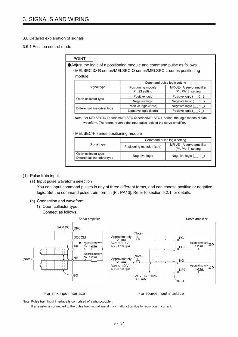
3. SIGNALS AND WIRING
3 - 31
3.6 Detailed explanation of signals
3.6.1 Position control mode
POINT
Adjust the logic of a positioning module and command pulse as follows.
MELSEC iQ-R series/MELSEC-Q series/MELSEC-L series positioning
module
Signal type
Command pulse logic setting
Positioning module Pr. 23 setting
MR-JE-_A servo amplifier [Pr. PA13] setting
Open-collector type
Positive logic Positive logic (_ _ 0 _)
Negative logic Negative logic (_ _ 1 _)
Differential line driver type
Positive logic (Note) Negative logic (_ _ 1 _)
Negative logic (Note) Positive logic (_ _ 0 _)
Note.
For MELSEC iQ-R series/MELSEC-Q series/MELSEC-L series, the logic means N-side
waveform. Therefore, reverse the input pulse logic of the servo amplifier.
MELSEC-F series positioning module
Signal type
Command pulse logic setting
Positioning module (fixed)
MR-JE-_A servo amplifier [Pr. PA13] setting
Open-collector type Differential line driver type
Negative logic Negative logic (_ _ 1 _)
(1) Pulse train input
(a) Input pulse waveform selection
You can input command pulses in any of three different forms, and can choose positive or negative
logic. Set the command pulse train form in [Pr. PA13]. Refer to section 5.2.1 for details.
(b) Connection and waveform
1) Open-collector type
Connect as follows.
Approximately1.2 kΩ
Approximately1.2 kΩ
SD
Servo amplifier
OPC
PP
NP
DOCOM
24 V DC
(Note)
Approximately1.2 kΩ
Servo amplifier
PP2
PG
VCES ≤ 1.0 VICEO ≤ 100 μA
(Note)
(Note)
Approximately20 mA
Approximately20 mA
Approximately1.2 kΩNP2
SD
NG
VCES ≤ 1.0 VICEO ≤ 100 μA
24 V DC ± 10%300 mA
For sink input interface For source input interface Note. Pulse train input interface is comprised of a photocoupler.
If a resistor is connected to the pulse train signal line, it may malfunction due to reduction in current.

3. SIGNALS AND WIRING
3 - 32
The following section explains about the case where the negative logic and the forward/reverse
rotation pulse trains are set to "_ _ 1 0" in [Pr. PA13].
Reverse rotation commandForward rotation command
(OFF)
(OFF) (OFF)(ON) (ON)
(ON) (OFF) (ON) (OFF) (ON)
(OFF)Forward rotation pulse train(transistor)Reverse rotation pulse train(transistor)
(ON)
2) Differential line driver type
Connect as follows.
PP
NP
Servo amplifier
PG
NG
SD
Approximately100Ω
Approximately100Ω
(Note)
Note. Pulse train input interface is comprised of a photocoupler.
If a resistor is connected to the pulse train signal line, it may malfunction due to
reduction in current.
The following example shows that an input waveform has been set to the negative logic and
forward/reverse rotation pulse trains by setting "_ _ 1 0" in [Pr. PA13]. The waveforms of PP, PG,
NP, and NG are based on LG.
Reverse rotation
PP
PG
NP
NG
Reverse rotationpulse train
Forward rotationpulse train
Forward rotation
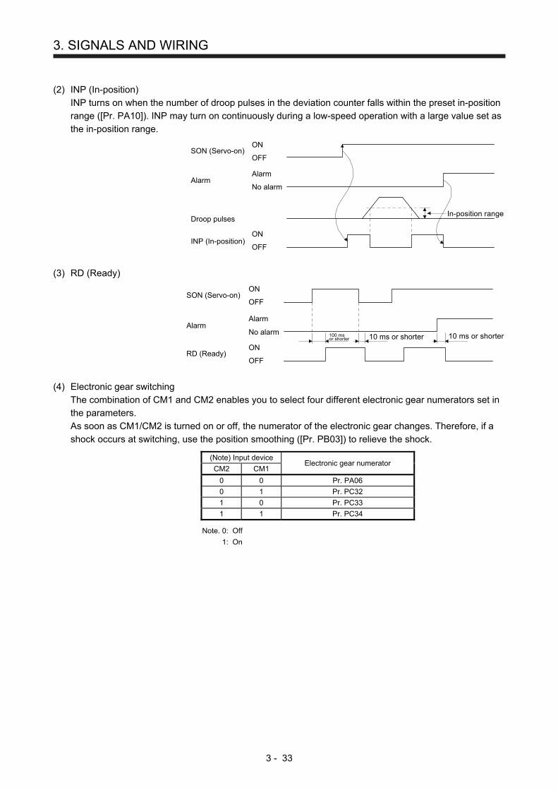
3. SIGNALS AND WIRING
3 - 33
(2) INP (In-position)
INP turns on when the number of droop pulses in the deviation counter falls within the preset in-position
range ([Pr. PA10]). INP may turn on continuously during a low-speed operation with a large value set as
the in-position range.
In-position range
INP (In-position)ON
OFF
ON
OFF
Alarm
No alarm
SON (Servo-on)
Alarm
Droop pulses
(3) RD (Ready)
RD (Ready)ON
OFF
ON
OFF
Alarm
No alarm
SON (Servo-on)
Alarm100 msor shorter 10 ms or shorter 10 ms or shorter
(4) Electronic gear switching
The combination of CM1 and CM2 enables you to select four different electronic gear numerators set in
the parameters.
As soon as CM1/CM2 is turned on or off, the numerator of the electronic gear changes. Therefore, if a
shock occurs at switching, use the position smoothing ([Pr. PB03]) to relieve the shock.
(Note) Input device Electronic gear numerator
CM2 CM1
0 0 Pr. PA06
0 1 Pr. PC32
1 0 Pr. PC33
1 1 Pr. PC34
Note. 0: Off
1: On
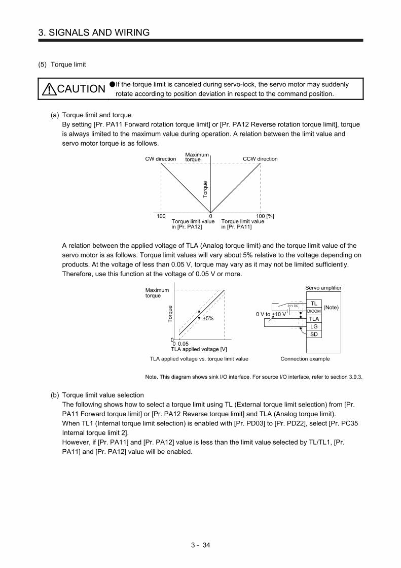
3. SIGNALS AND WIRING
3 - 34
(5) Torque limit
CAUTION If the torque limit is canceled during servo-lock, the servo motor may suddenly
rotate according to position deviation in respect to the command position.
(a) Torque limit and torque
By setting [Pr. PA11 Forward rotation torque limit] or [Pr. PA12 Reverse rotation torque limit], torque
is always limited to the maximum value during operation. A relation between the limit value and
servo motor torque is as follows.
Torque limit valuein [Pr. PA11]
Maximumtorque
Tor
que
0 100 [%]Torque limit valuein [Pr. PA12]
100
CCW directionCW direction
A relation between the applied voltage of TLA (Analog torque limit) and the torque limit value of the
servo motor is as follows. Torque limit values will vary about 5% relative to the voltage depending on
products. At the voltage of less than 0.05 V, torque may vary as it may not be limited sufficiently.
Therefore, use this function at the voltage of 0.05 V or more.
±5%
Connection exampleTLA applied voltage vs. torque limit value
TLA applied voltage [V]
Maximumtorque
Tor
que
00
0.05
Servo amplifier
24 V DC (Note)TL
DICOM
TLA
LG
SD
0 V to +10 V
Note. This diagram shows sink I/O interface. For source I/O interface, refer to section 3.9.3.
(b) Torque limit value selection
The following shows how to select a torque limit using TL (External torque limit selection) from [Pr.
PA11 Forward torque limit] or [Pr. PA12 Reverse torque limit] and TLA (Analog torque limit).
When TL1 (Internal torque limit selection) is enabled with [Pr. PD03] to [Pr. PD22], select [Pr. PC35
Internal torque limit 2].
However, if [Pr. PA11] and [Pr. PA12] value is less than the limit value selected by TL/TL1, [Pr.
PA11] and [Pr. PA12] value will be enabled.
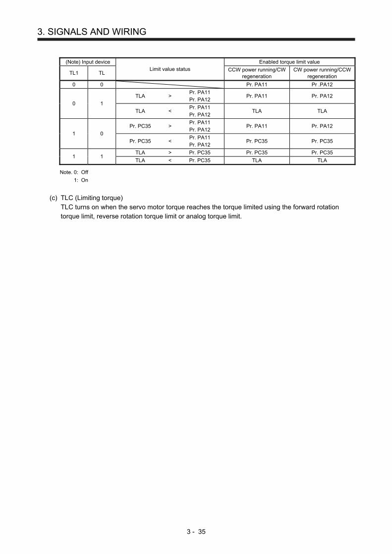
3. SIGNALS AND WIRING
3 - 35
(Note) Input device
Limit value status Enabled torque limit value
TL1 TL CCW power running/CW
regeneration CW power running/CCW
regeneration
0 0 Pr. PA11 Pr .PA12
0 1
TLA > Pr. PA11 Pr. PA12
Pr. PA11 Pr. PA12
TLA < Pr. PA11 Pr. PA12
TLA TLA
1 0
Pr. PC35 > Pr. PA11 Pr. PA12
Pr. PA11 Pr. PA12
Pr. PC35 < Pr. PA11 Pr. PA12
Pr. PC35 Pr. PC35
1 1 TLA > Pr. PC35 Pr. PC35 Pr. PC35
TLA < Pr. PC35 TLA TLA
Note. 0: Off
1: On
(c) TLC (Limiting torque)
TLC turns on when the servo motor torque reaches the torque limited using the forward rotation
torque limit, reverse rotation torque limit or analog torque limit.
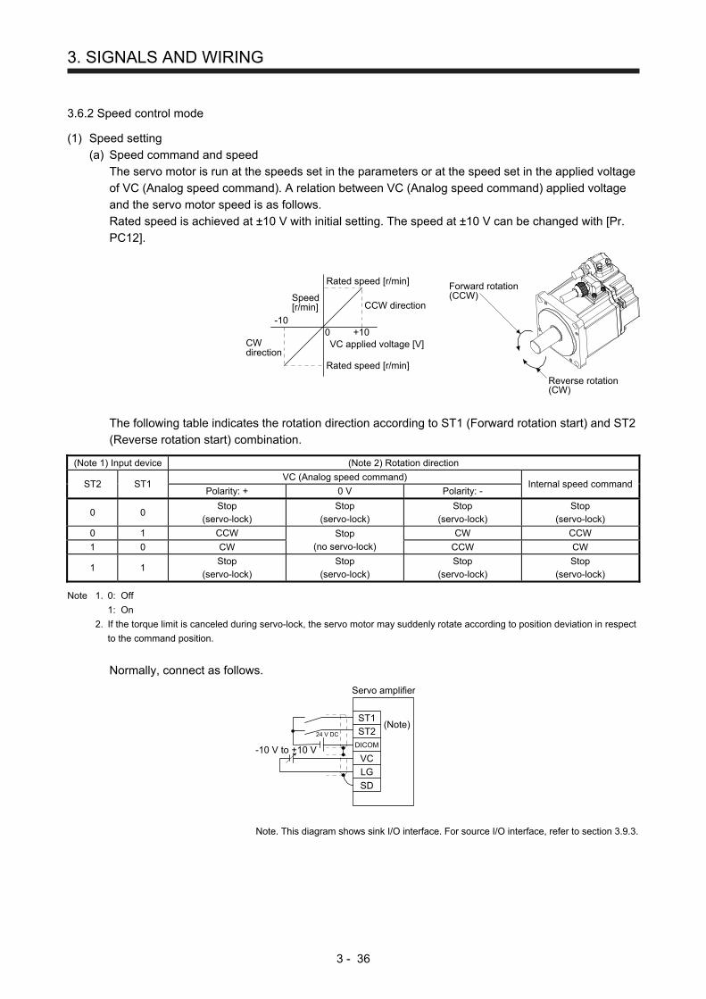
3. SIGNALS AND WIRING
3 - 36
3.6.2 Speed control mode
(1) Speed setting
(a) Speed command and speed
The servo motor is run at the speeds set in the parameters or at the speed set in the applied voltage
of VC (Analog speed command). A relation between VC (Analog speed command) applied voltage
and the servo motor speed is as follows.
Rated speed is achieved at ±10 V with initial setting. The speed at ±10 V can be changed with [Pr.
PC12].
Speed[r/min]
CWdirection
Rated speed [r/min]
Rated speed [r/min]
0
CCW direction
+10-10
VC applied voltage [V]
Forward rotation(CCW)
Reverse rotation(CW)
The following table indicates the rotation direction according to ST1 (Forward rotation start) and ST2
(Reverse rotation start) combination.
(Note 1) Input device (Note 2) Rotation direction
ST2 ST1 VC (Analog speed command)
Internal speed command Polarity: + 0 V Polarity: -
0 0 Stop
(servo-lock) Stop
(servo-lock) Stop
(servo-lock) Stop
(servo-lock)
0 1 CCW Stop (no servo-lock)
CW CCW
1 0 CW CCW CW
1 1 Stop
(servo-lock) Stop
(servo-lock) Stop
(servo-lock) Stop
(servo-lock) Note 1. 0: Off
1: On
2. If the torque limit is canceled during servo-lock, the servo motor may suddenly rotate according to position deviation in respect
to the command position.
Normally, connect as follows.
(Note)ST1
ST2DICOM
VC
LG
SD
Servo amplifier
24 V DC
-10 V to +10 V
Note. This diagram shows sink I/O interface. For source I/O interface, refer to section 3.9.3.

3. SIGNALS AND WIRING
3 - 37
(b) Speed command value selection
To select VC (Analog speed command) and a speed command value of internal speed commands 1
to 7, enable SP1 (Speed selection 1), SP2 (Speed selection 2), and SP3 (Speed selection 3) with
[Pr. PD03] to [Pr. PD20].
(Note) Input device Speed command value
SP3 SP2 SP1
0 0 0 VC (Analog speed command)
0 0 1 Pr. PC05 Internal speed command 1
0 1 0 Pr. PC06 Internal speed command 2
0 1 1 Pr. PC07 Internal speed command 3
1 0 0 Pr. PC08 Internal speed command 4
1 0 1 Pr. PC09 Internal speed command 5
1 1 0 Pr. PC10 Internal speed command 6
1 1 1 Pr. PC11 Internal speed command 7
Note. 0: Off
1: On
You can change the speed during rotation. To accelerate/decelerate, set acceleration/deceleration
time constant in [Pr. PC01] or [Pr. PC02].
When the internal speed commands are used to command a speed, the speed does not vary with
the ambient temperature.
(2) SA (Speed reached)
SA turns on when the servo motor speed has nearly reached the speed set to the internal speed
command or analog speed command.
Internal speedcommand 1
Internal speedcommand 2Set speed selection
ST1 or ST2 ONOFF
Servo motor speed
SA (Speed reached) ONOFF
(3) Torque limit
As in section 3.6.1 (5)
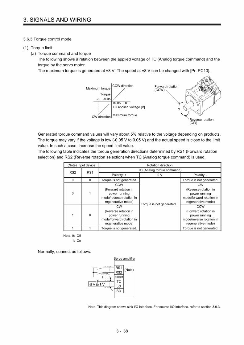
3. SIGNALS AND WIRING
3 - 38
3.6.3 Torque control mode
(1) Torque limit
(a) Torque command and torque
The following shows a relation between the applied voltage of TC (Analog torque command) and the
torque by the servo motor.
The maximum torque is generated at ±8 V. The speed at ±8 V can be changed with [Pr. PC13].
Forward rotation(CCW)
Reverse rotation(CW)
Maximum torque
Torque
CCW direction
TC applied voltage [V]
CW direction Maximum torque
-8+8
-0.05+0.05
Generated torque command values will vary about 5% relative to the voltage depending on products.
The torque may vary if the voltage is low (-0.05 V to 0.05 V) and the actual speed is close to the limit
value. In such a case, increase the speed limit value.
The following table indicates the torque generation directions determined by RS1 (Forward rotation
selection) and RS2 (Reverse rotation selection) when TC (Analog torque command) is used.
(Note) Input device Rotation direction
RS2 RS1 TC (Analog torque command)
Polarity: + 0 V Polarity: -
0 0 Torque is not generated.
Torque is not generated.
Torque is not generated.
0 1
CCW (Forward rotation in
power running mode/reverse rotation in
regenerative mode)
CW (Reverse rotation in
power running mode/forward rotation in
regenerative mode)
1 0
CW (Reverse rotation in
power running mode/forward rotation in
regenerative mode)
CCW (Forward rotation in
power running mode/reverse rotation in
regenerative mode)
1 1 Torque is not generated. Torque is not generated.
Note. 0: Off
1: On
Normally, connect as follows.
RS224 V DC
DICOM
TC
LG
SD
RS1
-8 V to 8 V
Servo amplifier
(Note)
Note. This diagram shows sink I/O interface. For source I/O interface, refer to section 3.9.3.
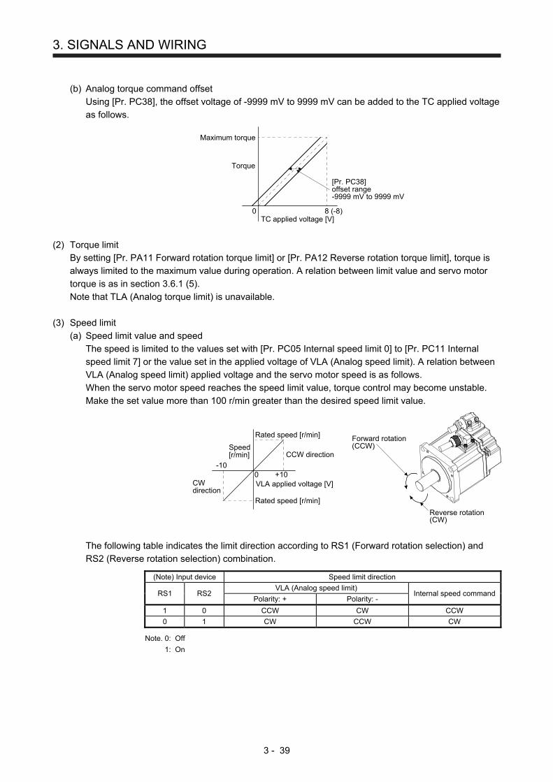
3. SIGNALS AND WIRING
3 - 39
(b) Analog torque command offset
Using [Pr. PC38], the offset voltage of -9999 mV to 9999 mV can be added to the TC applied voltage
as follows.
TC applied voltage [V]
Maximum torque
Torque
0 8 (-8)
[Pr. PC38]offset range-9999 mV to 9999 mV
(2) Torque limit
By setting [Pr. PA11 Forward rotation torque limit] or [Pr. PA12 Reverse rotation torque limit], torque is
always limited to the maximum value during operation. A relation between limit value and servo motor
torque is as in section 3.6.1 (5).
Note that TLA (Analog torque limit) is unavailable.
(3) Speed limit
(a) Speed limit value and speed
The speed is limited to the values set with [Pr. PC05 Internal speed limit 0] to [Pr. PC11 Internal
speed limit 7] or the value set in the applied voltage of VLA (Analog speed limit). A relation between
VLA (Analog speed limit) applied voltage and the servo motor speed is as follows.
When the servo motor speed reaches the speed limit value, torque control may become unstable.
Make the set value more than 100 r/min greater than the desired speed limit value.
Speed[r/min]
CWdirection
0
CCW direction
+10-10
VLA applied voltage [V]
Forward rotation(CCW)
Reverse rotation(CW)
Rated speed [r/min]
Rated speed [r/min]
The following table indicates the limit direction according to RS1 (Forward rotation selection) and
RS2 (Reverse rotation selection) combination.
(Note) Input device Speed limit direction
RS1 RS2 VLA (Analog speed limit)
Internal speed command Polarity: + Polarity: -
1 0 CCW CW CCW
0 1 CW CCW CW
Note. 0: Off
1: On
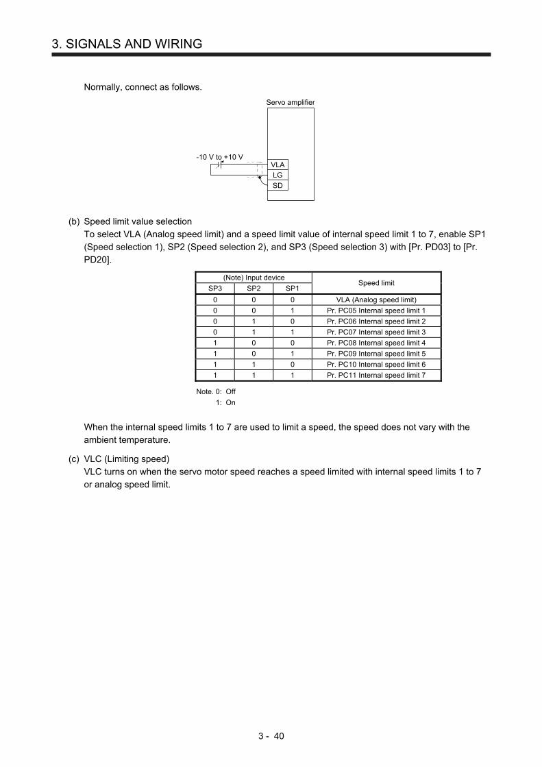
3. SIGNALS AND WIRING
3 - 40
Normally, connect as follows.
-10 V to +10 VVLA
LG
SD
Servo amplifier
(b) Speed limit value selection
To select VLA (Analog speed limit) and a speed limit value of internal speed limit 1 to 7, enable SP1
(Speed selection 1), SP2 (Speed selection 2), and SP3 (Speed selection 3) with [Pr. PD03] to [Pr.
PD20].
(Note) Input device Speed limit
SP3 SP2 SP1
0 0 0 VLA (Analog speed limit)
0 0 1 Pr. PC05 Internal speed limit 1
0 1 0 Pr. PC06 Internal speed limit 2
0 1 1 Pr. PC07 Internal speed limit 3
1 0 0 Pr. PC08 Internal speed limit 4
1 0 1 Pr. PC09 Internal speed limit 5
1 1 0 Pr. PC10 Internal speed limit 6
1 1 1 Pr. PC11 Internal speed limit 7
Note. 0: Off
1: On
When the internal speed limits 1 to 7 are used to limit a speed, the speed does not vary with the
ambient temperature.
(c) VLC (Limiting speed)
VLC turns on when the servo motor speed reaches a speed limited with internal speed limits 1 to 7
or analog speed limit.
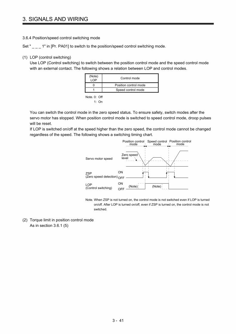
3. SIGNALS AND WIRING
3 - 41
3.6.4 Position/speed control switching mode
Set " _ _ _ 1" in [Pr. PA01] to switch to the position/speed control switching mode.
(1) LOP (control switching)
Use LOP (Control switching) to switch between the position control mode and the speed control mode
with an external contact. The following shows a relation between LOP and control modes.
(Note) LOP
Control mode
0 Position control mode
1 Speed control mode
Note. 0: Off
1: On
You can switch the control mode in the zero speed status. To ensure safety, switch modes after the
servo motor has stopped. When position control mode is switched to speed control mode, droop pulses
will be reset.
If LOP is switched on/off at the speed higher than the zero speed, the control mode cannot be changed
regardless of the speed. The following shows a switching timing chart.
Zero speedlevel
Position controlmode
ON
OFF
ON
OFFLOP(Control switching)
ZSP(Zero speed detection)
Servo motor speed
Speed controlmode
Position controlmode
(Note)(Note)
Note. When ZSP is not turned on, the control mode is not switched even if LOP is turned
on/off. After LOP is turned on/off, even if ZSP is turned on, the control mode is not
switched.
(2) Torque limit in position control mode
As in section 3.6.1 (5)

3. SIGNALS AND WIRING
3 - 42
(3) Speed setting in speed control mode
(a) Speed command and speed
The servo motor is run at the speeds set in the parameters or at the speed set in the applied voltage
of VC (Analog speed command). The relation between an applied voltage of VC (Analog speed
command) and servo motor speed, and the rotation direction with turning on ST1/ST2 are the same
as section 3.6.2 (1) (a).
Normally, connect as follows.
(Note)ST1
ST2DICOM
VC
LG
SD
Servo amplifier
24 V DC
-10 V to +10 V
Note. This diagram shows sink I/O interface. For source I/O interface, refer to section 3.9.3.
(b) Speed command value selection
To select VC (Analog speed command) and a speed command value of internal speed commands 1
to 7, enable SP1 (Speed selection 1), SP2 (Speed selection 2), and SP3 (Speed selection 3) with
[Pr. PD03] to [Pr. PD20].
(Note) Input device Speed command value
SP3 SP2 SP1
0 0 0 VC (Analog speed command)
0 0 1 Pr. PC05 Internal speed command 1
0 1 0 Pr. PC06 Internal speed command 2
0 1 1 Pr. PC07 Internal speed command 3
1 0 0 Pr. PC08 Internal speed command 4
1 0 1 Pr. PC09 Internal speed command 5
1 1 0 Pr. PC10 Internal speed command 6
1 1 1 Pr. PC11 Internal speed command 7
Note. 0: Off
1: On
You can change the speed during rotation. Acceleration/deceleration is performed with the setting
values of [Pr. PC01] and [Pr. PC02].
When the internal speed commands 1 to 7 are used to command a speed, the speed does not vary
with the ambient temperature.
(c) SA (Speed reached)
As in section 3.6.2 (2)
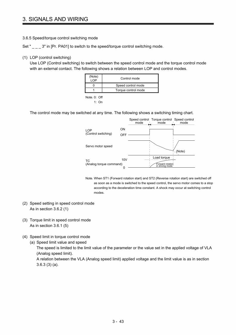
3. SIGNALS AND WIRING
3 - 43
3.6.5 Speed/torque control switching mode
Set " _ _ _ 3" in [Pr. PA01] to switch to the speed/torque control switching mode.
(1) LOP (control switching)
Use LOP (Control switching) to switch between the speed control mode and the torque control mode
with an external contact. The following shows a relation between LOP and control modes.
(Note) LOP
Control mode
0 Speed control mode
1 Torque control mode
Note. 0: Off
1: On
The control mode may be switched at any time. The following shows a switching timing chart.
LOP(Control switching)
Servo motor speed
TC(Analog torque command)
ON
OFF
10V
0
(Note)
Load torque
Speed controlmode
Torque controlmode
Speed controlmode
Forward rotationin driving mode
Note. When ST1 (Forward rotation start) and ST2 (Reverse rotation start) are switched off
as soon as a mode is switched to the speed control, the servo motor comes to a stop
according to the deceleration time constant. A shock may occur at switching control
modes.
(2) Speed setting in speed control mode
As in section 3.6.2 (1)
(3) Torque limit in speed control mode
As in section 3.6.1 (5)
(4) Speed limit in torque control mode
(a) Speed limit value and speed
The speed is limited to the limit value of the parameter or the value set in the applied voltage of VLA
(Analog speed limit).
A relation between the VLA (Analog speed limit) applied voltage and the limit value is as in section
3.6.3 (3) (a).
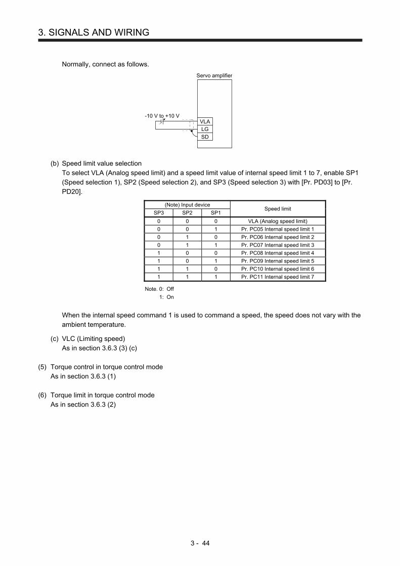
3. SIGNALS AND WIRING
3 - 44
Normally, connect as follows.
-10 V to +10 VVLA
LG
SD
Servo amplifier
(b) Speed limit value selection
To select VLA (Analog speed limit) and a speed limit value of internal speed limit 1 to 7, enable SP1
(Speed selection 1), SP2 (Speed selection 2), and SP3 (Speed selection 3) with [Pr. PD03] to [Pr.
PD20].
(Note) Input device Speed limit
SP3 SP2 SP1
0 0 0 VLA (Analog speed limit)
0 0 1 Pr. PC05 Internal speed limit 1
0 1 0 Pr. PC06 Internal speed limit 2
0 1 1 Pr. PC07 Internal speed limit 3
1 0 0 Pr. PC08 Internal speed limit 4
1 0 1 Pr. PC09 Internal speed limit 5
1 1 0 Pr. PC10 Internal speed limit 6
1 1 1 Pr. PC11 Internal speed limit 7
Note. 0: Off
1: On
When the internal speed command 1 is used to command a speed, the speed does not vary with the
ambient temperature.
(c) VLC (Limiting speed)
As in section 3.6.3 (3) (c)
(5) Torque control in torque control mode
As in section 3.6.3 (1)
(6) Torque limit in torque control mode
As in section 3.6.3 (2)
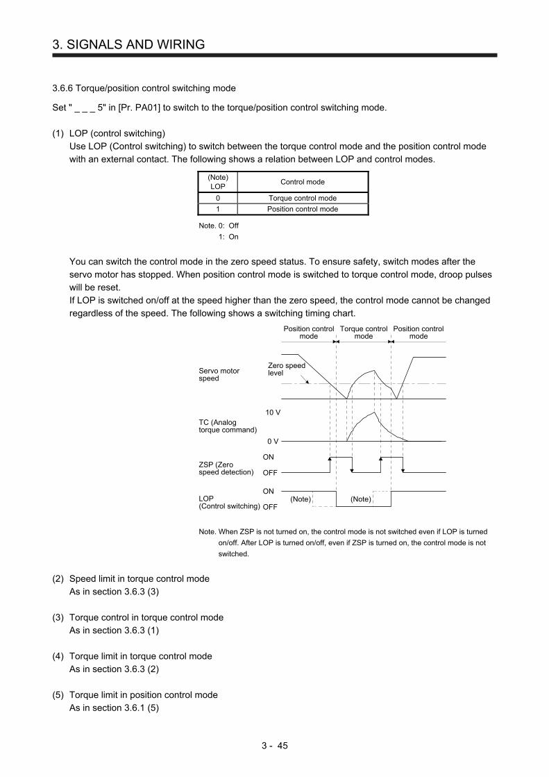
3. SIGNALS AND WIRING
3 - 45
3.6.6 Torque/position control switching mode
Set " _ _ _ 5" in [Pr. PA01] to switch to the torque/position control switching mode.
(1) LOP (control switching)
Use LOP (Control switching) to switch between the torque control mode and the position control mode
with an external contact. The following shows a relation between LOP and control modes.
(Note) LOP
Control mode
0 Torque control mode
1 Position control mode
Note. 0: Off
1: On
You can switch the control mode in the zero speed status. To ensure safety, switch modes after the
servo motor has stopped. When position control mode is switched to torque control mode, droop pulses
will be reset.
If LOP is switched on/off at the speed higher than the zero speed, the control mode cannot be changed
regardless of the speed. The following shows a switching timing chart.
Zero speedlevel
Torque controlmode
Position controlmode
Position controlmode
Servo motorspeed
TC (Analogtorque command)
ZSP (Zerospeed detection)
LOP(Control switching)
0 V
OFF
(Note) (Note)ON
OFF
ON
10 V
Note. When ZSP is not turned on, the control mode is not switched even if LOP is turned
on/off. After LOP is turned on/off, even if ZSP is turned on, the control mode is not
switched.
(2) Speed limit in torque control mode
As in section 3.6.3 (3)
(3) Torque control in torque control mode
As in section 3.6.3 (1)
(4) Torque limit in torque control mode
As in section 3.6.3 (2)
(5) Torque limit in position control mode
As in section 3.6.1 (5)

3. SIGNALS AND WIRING
3 - 46
3.7 Forced stop deceleration function
POINT
When alarms not related to the forced stop function occur, control of motor
deceleration can not be guaranteed. (Refer to chapter 8.)
In the torque control mode, the forced stop deceleration function is not available.
3.7.1 Forced stop deceleration function
When EM2 is turned off, dynamic brake will start to stop the servo motor after forced stop deceleration.
During this sequence, the display shows [AL. E6 Servo forced stop warning].
During normal operation, do not use EM2 (Forced stop 2) to alternate stop and drive. The the servo amplifier
life may be shortened.
(1) Connection diagram
Servo amplifier
Forced stop 2
DICOM
EM2
24 V DC
(Note)
Note. This diagram shows sink I/O interface. For source I/O interface, refer to section
3.9.3.
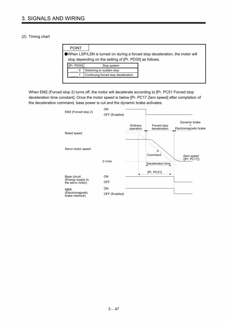
3. SIGNALS AND WIRING
3 - 47
(2) Timing chart
POINT
When LSP/LSN is turned on during a forced stop deceleration, the motor will
stop depending on the setting of [Pr. PD30] as follows.
[Pr. PD30] Stop system
_ _ _ 0 Switching to sudden stop
_ _ _ 1 Continuing forced stop deceleration
When EM2 (Forced stop 2) turns off, the motor will decelerate according to [Pr. PC51 Forced stop
deceleration time constant]. Once the motor speed is below [Pr. PC17 Zero speed] after completion of
the deceleration command, base power is cut and the dynamic brake activates.
Base circuit(Energy supply tothe servo motor)
0 r/min
Servo motor speed
MBR(Electromagneticbrake interlock)
ON
OFF (Enabled)
ON
OFF
Deceleration time
Command
Rated speed
Ordinaryoperation
Forced stopdeceleration
Dynamic brake+
Electromagnetic brake
ON
OFF (Enabled)EM2 (Forced stop 2)
Zero speed([Pr. PC17])
[Pr. PC51]
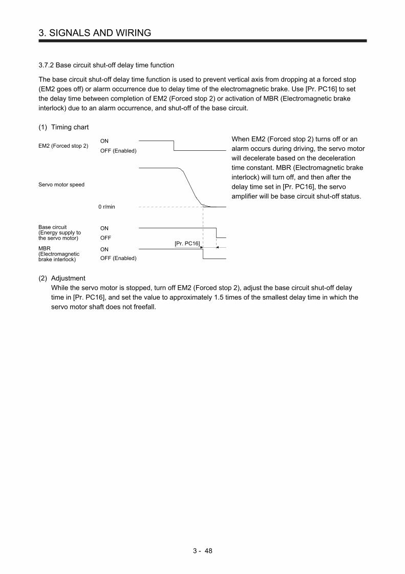
3. SIGNALS AND WIRING
3 - 48
3.7.2 Base circuit shut-off delay time function
The base circuit shut-off delay time function is used to prevent vertical axis from dropping at a forced stop
(EM2 goes off) or alarm occurrence due to delay time of the electromagnetic brake. Use [Pr. PC16] to set
the delay time between completion of EM2 (Forced stop 2) or activation of MBR (Electromagnetic brake
interlock) due to an alarm occurrence, and shut-off of the base circuit.
(1) Timing chart
MBR(Electromagneticbrake interlock)
ON
OFF (Enabled)
Base circuit(Energy supply tothe servo motor)
0 r/min
Servo motor speed
ON
OFF (Enabled)EM2 (Forced stop 2)
ON
OFF[Pr. PC16]
When EM2 (Forced stop 2) turns off or an
alarm occurs during driving, the servo motor
will decelerate based on the deceleration
time constant. MBR (Electromagnetic brake
interlock) will turn off, and then after the
delay time set in [Pr. PC16], the servo
amplifier will be base circuit shut-off status.
(2) Adjustment
While the servo motor is stopped, turn off EM2 (Forced stop 2), adjust the base circuit shut-off delay
time in [Pr. PC16], and set the value to approximately 1.5 times of the smallest delay time in which the
servo motor shaft does not freefall.

3. SIGNALS AND WIRING
3 - 49
3.7.3 Vertical axis freefall prevention function
The vertical axis freefall prevention function avoids machine damage by pulling up the shaft slightly like the
following case.
When the servo motor is used for operating vertical axis, the servo motor electromagnetic brake and the
base circuit shut-off delay time function avoid dropping axis at forced stop. However, the functions may not
avoid dropping axis a few μm due to the backlash of the servo motor electromagnetic brake.
The vertical axis freefall prevention function is enabled with the following conditions.
Other than "0" is set to [Pr. PC54 Vertical axis freefall prevention compensation amount].
The servo motor speed decelerates lower than the value of zero speed by turning off EM2 (Forced stop
2) or by an alarm occurrence.
The base circuit shut-off delay time function is enabled.
EM2 (Forced stop 2) turned off or an alarm occurred while the servo motor speed is zero speed or less.
(1) Timing chart
MBR(Electromagneticbrake interlock)
ON
OFF (Enabled)
Base circuit(Energy supply tothe servo motor)
ON
OFF
Actual operation ofelectromagnetic brake
Disabled
Enabled
Position Travel distance
ON
OFF (Enabled)EM2 (Forced stop 2)
Set the base circuit shut-off delay time. ([Pr. PC16])
(2) Adjustment
Set the freefall prevention compensation amount in [Pr. PC54].
While the servo motor is stopped, turn off the EM2 (Forced stop 2). Adjust the base circuit shut-off
delay time in [Pr. PC16] in accordance with the travel distance ([Pr. PC54). Adjust it considering the
freefall prevention compensation amount by checking the servo motor speed, torque ripple, etc.
3.7.4 Residual risks of the forced stop function (EM2)
(1) The forced stop function is not available for alarms that activate the dynamic brake when the alarms
occur.
(2) When an alarm that activates the dynamic brake during forced stop deceleration occurs, the braking
distance until the servo motor stops will be longer than that of normal forced stop deceleration without
the dynamic brake.
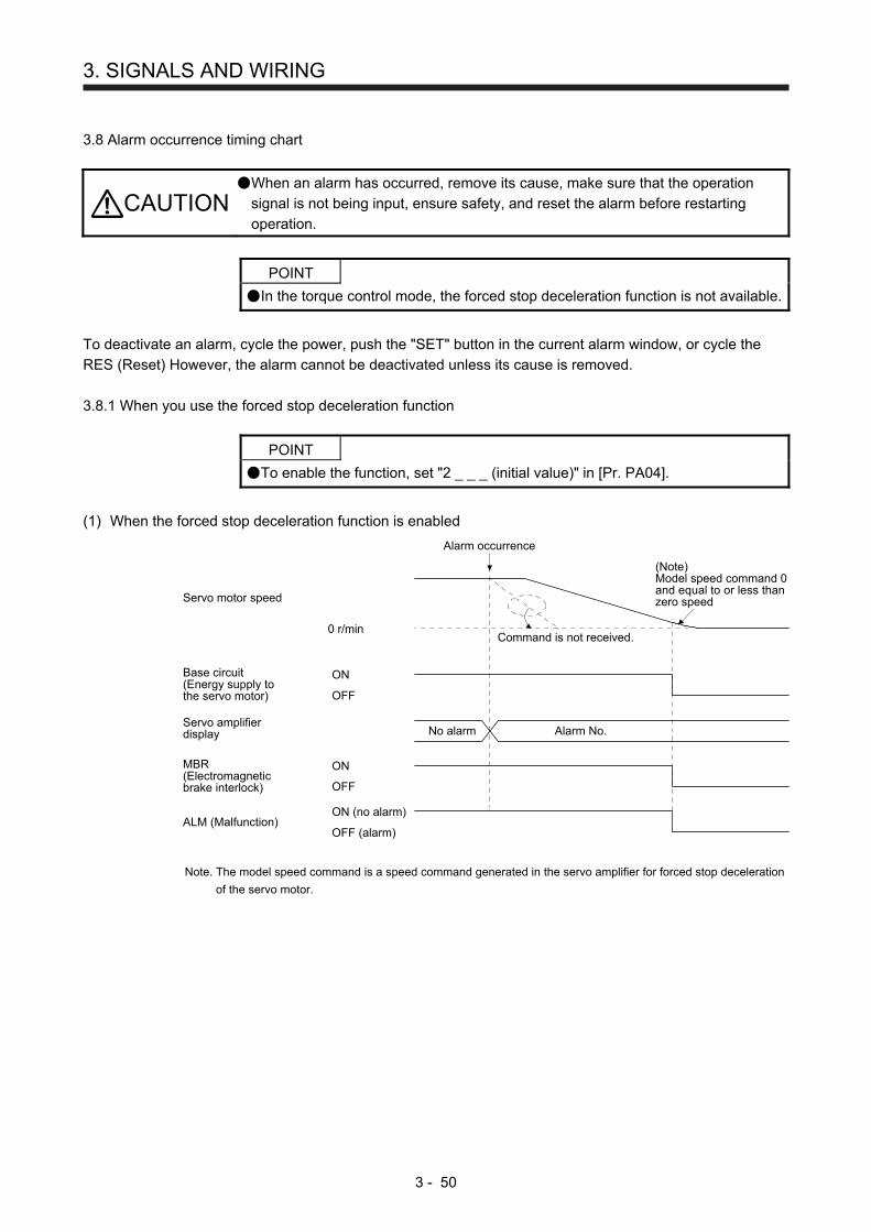
3. SIGNALS AND WIRING
3 - 50
3.8 Alarm occurrence timing chart
CAUTION When an alarm has occurred, remove its cause, make sure that the operation
signal is not being input, ensure safety, and reset the alarm before restarting
operation.
POINT
In the torque control mode, the forced stop deceleration function is not available.
To deactivate an alarm, cycle the power, push the "SET" button in the current alarm window, or cycle the
RES (Reset) However, the alarm cannot be deactivated unless its cause is removed.
3.8.1 When you use the forced stop deceleration function
POINT
To enable the function, set "2 _ _ _ (initial value)" in [Pr. PA04].
(1) When the forced stop deceleration function is enabled
Command is not received.
Alarm occurrence
Alarm No.No alarm
(Note)Model speed command 0and equal to or less thanzero speed
MBR(Electromagneticbrake interlock)
ON
OFF
ON (no alarm)
OFF (alarm)
Base circuit(Energy supply tothe servo motor)
ON
OFF
Servo amplifierdisplay
0 r/min
Servo motor speed
ALM (Malfunction)
Note. The model speed command is a speed command generated in the servo amplifier for forced stop deceleration
of the servo motor.
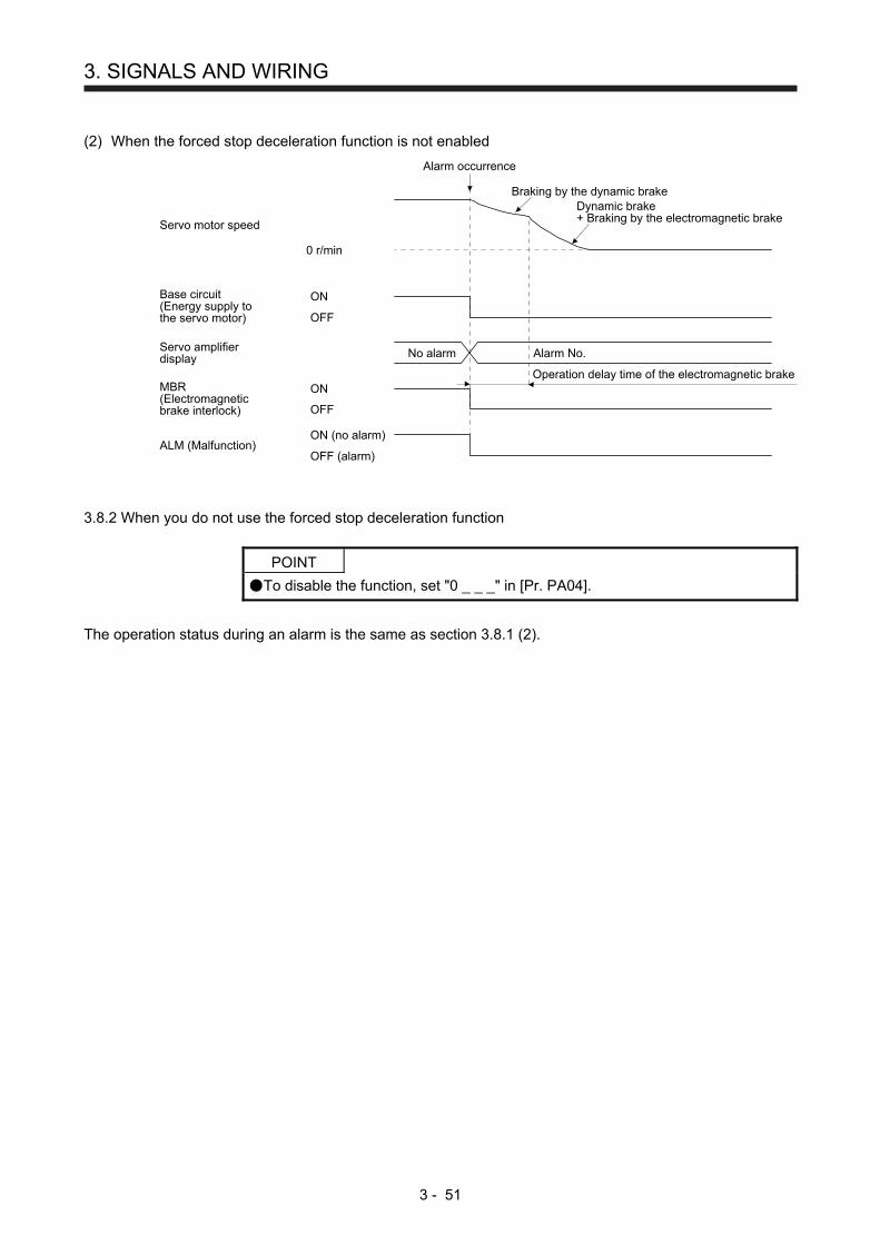
3. SIGNALS AND WIRING
3 - 51
(2) When the forced stop deceleration function is not enabled
MBR(Electromagneticbrake interlock)
ON
OFF
ON (no alarm)
OFF (alarm)
Base circuit(Energy supply tothe servo motor)
ON
OFF
Servo amplifierdisplay
0 r/min
Servo motor speed
ALM (Malfunction)
No alarm Alarm No.
Braking by the dynamic brakeDynamic brake+ Braking by the electromagnetic brake
Operation delay time of the electromagnetic brake
Alarm occurrence
3.8.2 When you do not use the forced stop deceleration function
POINT
To disable the function, set "0 _ _ _" in [Pr. PA04].
The operation status during an alarm is the same as section 3.8.1 (2).

3. SIGNALS AND WIRING
3 - 52
3.9 Interfaces
3.9.1 Internal connection diagram
The following diagram is for sink I/O interface when command pulse train input is differential line driver type.
3
SON SON SON
CN1
15RES ST1 19
CR ST2 41
EM2 42
LSN 44
OPC 12
20
21
LSN
LSP 43LSP
DICOM
DICOM
RS2
RS1
P S T
CN1
47
23
24
48
49
DOCOM
46 DOCOM
ZSP
INP
RD
ZSP
ALM
RD
ZSP
RD
SA
P S T
CN1 P S T
4
5
6
7
8
9
33
34
LA
LAR
LB
LBR
LZ
LZR
OP
LG
CN1 P S T
MO1
MO2
LG
26
29
30
Differential linedriver output(35 mA or lower)
Open-collectoroutput
CN1P S T
2VC VLA
27TLA TLA TC
3LG
CaseSD
Approx.6.2 kΩ
Approx.6.2 kΩ
Analog monitor
Servo amplifier
(Note 4)24 V DC
CN2 P S T
2
4
7
8
MR
MRR
MD
MDR
LG
Encoder
E
Servo motor
(Note 3)(Note 3)
USB
P S T
D+
GND
D- 2
3
5
CN3
(Note 1)
(Note 1)
(Note 1)
(Note 1)
(Note 1)
(Note 1)
(Note 1)
± 10 V DC
± 10 V DC
(Note 4)24 V DC
RA
RA
M
Insulated
13
14
39
40
28
31
CN1 P S T
SDP
SDN
RDP
RDN
LG
TRE
RS-422/RS-485
(Note 1)
(Note 5)
PP 10
PG 11NP 35
PP2 37
NP2 38NG 36
Approx. 100 ΩApprox.1.2 kΩ
Approx. 100 ΩApprox.1.2 kΩ
(Note 2)
Approx.1.2 kΩ
Approx.1.2 kΩ

3. SIGNALS AND WIRING
3 - 53
Note 1. P: position control mode, S: speed control mode, T: torque control mode
2. This is for the differential line driver pulse train input. For the open-collector pulse train input, connect as follows.
DOCOM 46
OPC 12
20
47
PP 10
PG 11
NP 35
NG 36
DICOM
DOCOM
PP2 37
NP2 38
24 V DC
DOCOM 46
OPC 12
20
47
PP 10
PG 11
NP 35
NG 36
DICOM
DOCOM
PP2 37
NP2 38
24 V DC
For sink input interface For source input interface 3. This diagram shows sink I/O interface. For source I/O interface, refer to section 3.9.3.
4. The illustration of the 24 V DC power supply is divided between input signal and output signal for convenience. However, they
can be configured by one.
5. To use the RS-422/RS-485 communication function, connect between TRE and RDN of the final axis servo amplifier. (Refer to
section 12.1.1.)

3. SIGNALS AND WIRING
3 - 54
3.9.2 Detailed explanation of interfaces
This section provides the details of the I/O signal interfaces (refer to the I/O division in the table) given in
section 3.5. Refer to this section and make connection with the external device.
(1) Digital input interface DI-1
This is an input circuit whose photocoupler cathode side is input terminal. Transmit signals from sink
(open-collector) type transistor output, relay switch, etc. The following is a connection diagram for sink
input. Refer to section 3.9.3 for source input.
Approximately6.2 kΩ
Approximately5 mA
TR
24 V DC ± 10%300 mA
Switch
For transistor
EM2etc.
Servo amplifier
DICOM
VCES 1.0 VICEO 100 A
The following shows when the CN1-10 pin and the CN1-35 pin are used as digital input interface:
Approximately1.2 kΩ
Servo amplifier24 V DC ± 10%300 mA OPC
CN1-10, CN1-35
DOCOM
SD
10 m or less
Approximately20 mA
VCES ≤ 1.0 VICEO ≤
(2) Digital output interface DO-1
This is a circuit in which the collector side of the output transistor is the output terminal. When the output
transistor is turned on, the current flows from the collector terminal.
A lamp, relay or photocoupler can be driven. Install a diode (D) for an inductive load, or install an inrush
current suppressing resistor (R) for a lamp load.
(Rated current: 40 mA or less, maximum current: 50 mA or less, inrush current: 100 mA or less) A
maximum of 2.6 V voltage drop occurs in the servo amplifier.
The following shows a connection diagram for sink output. Refer to section 3.9.3 for source output.
(Note) 24 V DC ± 10%300 mA
If polarity of diode isreversed, servo amplifierwill malfunction.
Servo amplifier
ALMetc.
Load
DOCOM
Note. If the voltage drop (maximum of 2.6 V) interferes with the relay operation, apply high
voltage (maximum of 26.4 V) from external source.
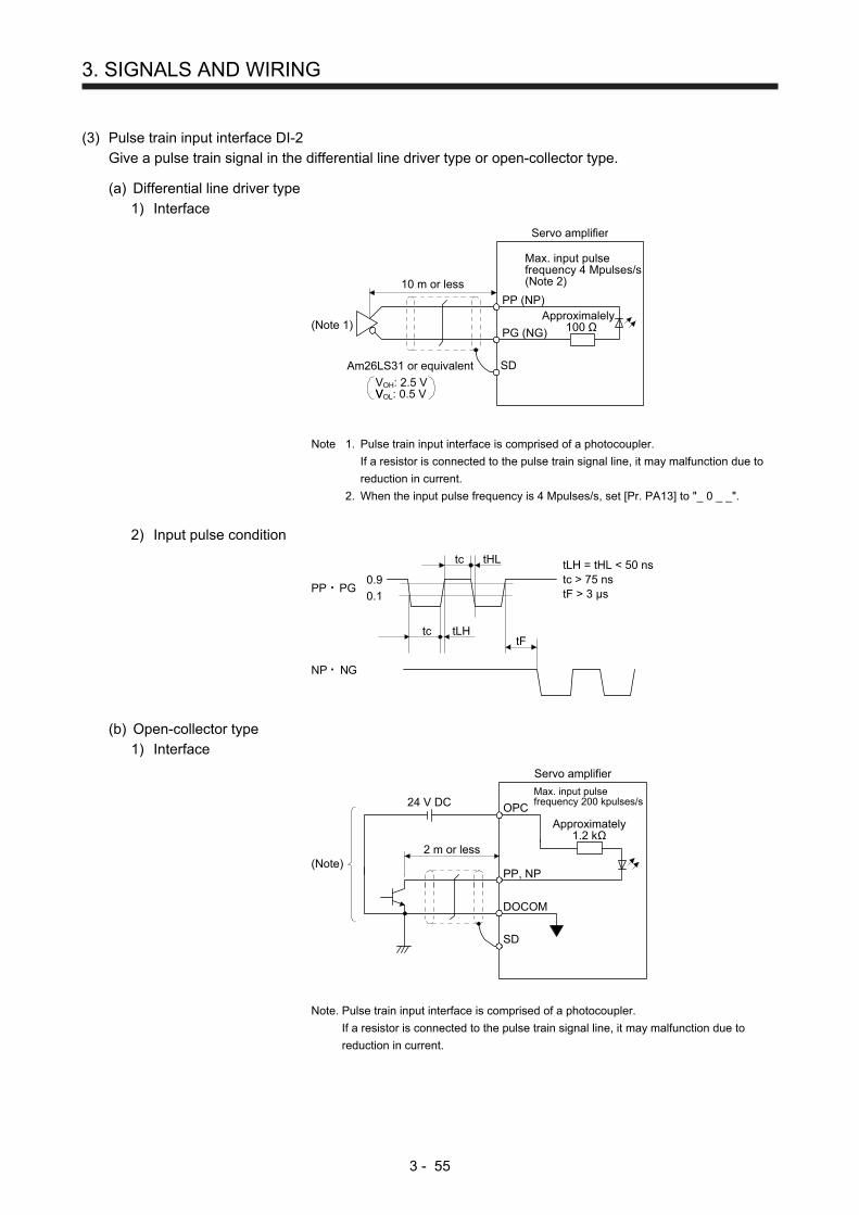
3. SIGNALS AND WIRING
3 - 55
(3) Pulse train input interface DI-2
Give a pulse train signal in the differential line driver type or open-collector type.
(a) Differential line driver type
1) Interface
SD
PG (NG)
PP (NP)
Max. input pulsefrequency 4 Mpulses/s(Note 2)
Servo amplifier
Am26LS31 or equivalent
Approximalely100 Ω
VOH: 2.5 VVOL: 0.5 VV
(Note 1)
10 m or less
Note 1. Pulse train input interface is comprised of a photocoupler.
If a resistor is connected to the pulse train signal line, it may malfunction due to
reduction in current.
2. When the input pulse frequency is 4 Mpulses/s, set [Pr. PA13] to "_ 0 _ _".
2) Input pulse condition
0.9
0.1
tc tLH
tc tHL
tF
PP PG
NP NG
tLH = tHL < 50 nstc > 75 nstF > 3 µs
(b) Open-collector type
1) Interface
Approximately1.2 kΩ
Servo amplifier
24 V DC OPC
PP, NP
DOCOM
SD
Max. input pulsefrequency 200 kpulses/s
2 m or less(Note)
Note. Pulse train input interface is comprised of a photocoupler.
If a resistor is connected to the pulse train signal line, it may malfunction due to
reduction in current.
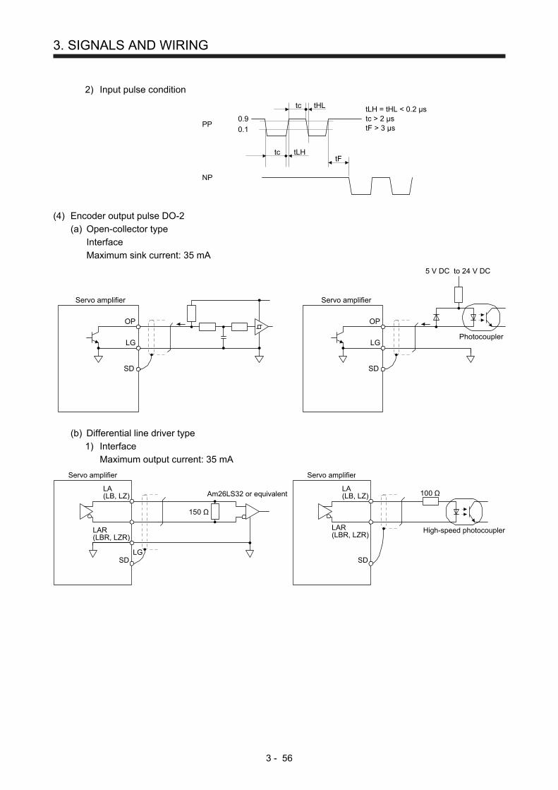
3. SIGNALS AND WIRING
3 - 56
2) Input pulse condition
0.9
0.1
tc tLH
tc tHL
tF
PP
NP
tLH = tHL < 0.2 µstc > 2 µstF > 3 µs
(4) Encoder output pulse DO-2
(a) Open-collector type
Interface
Maximum sink current: 35 mA
Photocoupler
Servo amplifier
OP
LG
SD
Servo amplifier
OP
LG
SD
5 V DC to 24 V DC
(b) Differential line driver type
1) Interface
Maximum output current: 35 mA
150 Ω
100 ΩAm26LS32 or equivalent
Servo amplifier
LA(LB, LZ)
LAR(LBR, LZR)
SDLG
High-speed photocoupler
Servo amplifier
LAR(LBR, LZR)
SD
LA(LB, LZ)

3. SIGNALS AND WIRING
3 - 57
2) Output pulse
/2
T
400 s or more
Time cycle (T) is determined by the settings of[Pr. PA15] and [Pr. PC19].
LA
LAR
LB
LBR
LZLZR
OP
Servo motor CCW rotation
(5) Analog input
Input impedance
10 kΩ to 12 kΩ
VC etc.
LG
SD
Approx.10 kΩ
Servo amplifier
(6) Analog output
Output voltage: ±10 V (Note)Maximum output current: 1 mAResolution: 10 bits or equivalentLG
MO1(MO2)
Servo amplifier
Note. Output voltage range varies depending on the monitored signal.
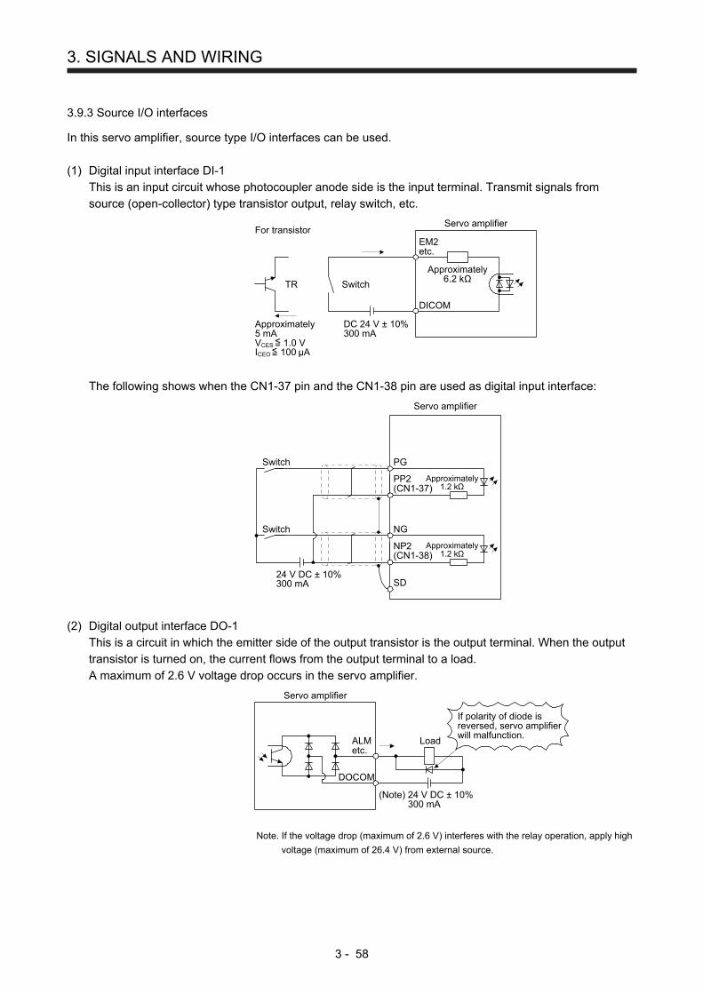
3. SIGNALS AND WIRING
3 - 58
3.9.3 Source I/O interfaces
In this servo amplifier, source type I/O interfaces can be used.
(1) Digital input interface DI-1
This is an input circuit whose photocoupler anode side is the input terminal. Transmit signals from
source (open-collector) type transistor output, relay switch, etc.
Approximately6.2 kΩ
DC 24 V ± 10%300 mA
Switch
For transistorEM2etc.
Servo amplifier
DICOM
Approximately5 mAVCES 1.0 VICEO 100 A
TR
The following shows when the CN1-37 pin and the CN1-38 pin are used as digital input interface:
Approximately1.2 kΩ
Servo amplifier
PP2(CN1-37)
PGSwitch
Approximately1.2 kΩ
NP2(CN1-38)
NG
SD24 V DC ± 10%300 mA
Switch
(2) Digital output interface DO-1
This is a circuit in which the emitter side of the output transistor is the output terminal. When the output
transistor is turned on, the current flows from the output terminal to a load.
A maximum of 2.6 V voltage drop occurs in the servo amplifier.
(Note) 24 V DC ± 10%300 mA
Servo amplifier
ALMetc.
DOCOM
Load
If polarity of diode isreversed, servo amplifierwill malfunction.
Note. If the voltage drop (maximum of 2.6 V) interferes with the relay operation, apply high
voltage (maximum of 26.4 V) from external source.

3. SIGNALS AND WIRING
3 - 59
(3) Pulse train input interface DI-2
Give a pulse train signal in the open-collector type.
1) Interface
Maximum input pulsefrequency 200 kpulses/s
Approximately1.2 kΩ
Servo amplifier
PP2
PG
VCES ≤ 1.0 VICEO ≤
(Note)Approximately
20 mA
Approximately20 mA
(Note)
Approximately1.2 kΩNP2
SD
NG
VCES ≤ 1.0 VICEO ≤
24 V DC ± 10%300 mA
Note. Pulse train input interface is comprised of a photocoupler.
If a resistor is connected to the pulse train signal line, it may malfunction due to
reduction in current.
2) Input pulse condition
0.9
0.1
tc tLH
tc tHL
tF
PP2
NP2
tLH = tHL < 0.2 µstc > 2 µstF > 3 µs
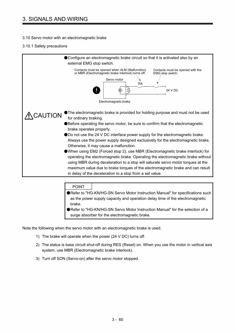
3. SIGNALS AND WIRING
3 - 60
3.10 Servo motor with an electromagnetic brake
3.10.1 Safety precautions
CAUTION
Configure an electromagnetic brake circuit so that it is activated also by an
external EMG stop switch.
Servo motor
Electromagnetic brake
B U
RA
Contacts must be opened when ALM (Malfunction)or MBR (Electromagnetic brake interlock) turns off.
24 V DC
Contacts must be opened with theEMG stop switch.
The electromagnetic brake is provided for holding purpose and must not be used
for ordinary braking.
Before operating the servo motor, be sure to confirm that the electromagnetic
brake operates properly.
Do not use the 24 V DC interface power supply for the electromagnetic brake.
Always use the power supply designed exclusively for the electromagnetic brake.
Otherwise, it may cause a malfunction.
When using EM2 (Forced stop 2), use MBR (Electromagnetic brake interlock) for
operating the electromagnetic brake. Operating the electromagnetic brake without
using MBR during deceleration to a stop will saturate servo motor torques at the
maximum value due to brake torques of the electromagnetic brake and can result
in delay of the deceleration to a stop from a set value.
POINT
Refer to "HG-KN/HG-SN Servo Motor Instruction Manual" for specifications such
as the power supply capacity and operation delay time of the electromagnetic
brake.
Refer to "HG-KN/HG-SN Servo Motor Instruction Manual" for the selection of a
surge absorber for the electromagnetic brake.
Note the following when the servo motor with an electromagnetic brake is used.
1) The brake will operate when the power (24 V DC) turns off.
2) The status is base circuit shut-off during RES (Reset) on. When you use the motor in vertical axis
system, use MBR (Electromagnetic brake interlock).
3) Turn off SON (Servo-on) after the servo motor stopped.
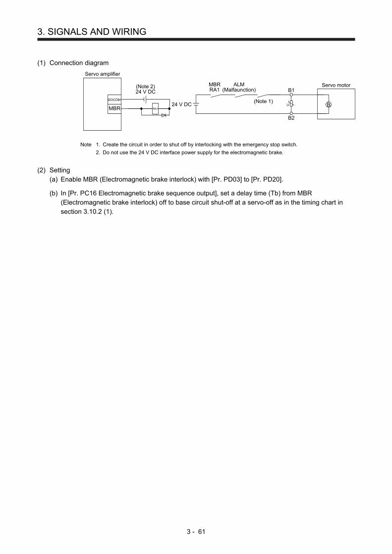
3. SIGNALS AND WIRING
3 - 61
(1) Connection diagram
B2
B1
MBR
DOCOM
RA1U B
Servo motor
24 V DC
ALM(Malfaunction)
Servo amplifier
MBRRA1
(Note 1)
(Note 2)24 V DC
Note 1. Create the circuit in order to shut off by interlocking with the emergency stop switch.
2. Do not use the 24 V DC interface power supply for the electromagnetic brake.
(2) Setting
(a) Enable MBR (Electromagnetic brake interlock) with [Pr. PD03] to [Pr. PD20].
(b) In [Pr. PC16 Electromagnetic brake sequence output], set a delay time (Tb) from MBR
(Electromagnetic brake interlock) off to base circuit shut-off at a servo-off as in the timing chart in
section 3.10.2 (1).

3. SIGNALS AND WIRING
3 - 62
3.10.2 Timing chart
(1) When you use the forced stop deceleration function
POINT
To enable the function, set "2 _ _ _ (initial value)" in [Pr. PA04].
(a) SON (Servo-on) on/off
When SON (Servo-on) is turned off, the servo lock will be released after Tb [ms], and the servo
motor will coast. If the electromagnetic brake is enabled during servo-lock, the brake life may be
shorter. Therefore, set Tb about 1.5 times of the minimum delay time where the moving part will not
drop down for a vertical axis system, etc.
Approx. 95 ms
Approx. 95 msMBR(Electromagneticbrake interlock)
(Note 1)ON
OFF
ON
OFF
0 r/min
Base circuit
Servo motor speed
SON (Servo-on)ON
OFF
Coasting
Operation delay time ofthe electromagnetic brake
Release
Activate
Position command(Note 4)
Electromagneticbrake Release delay time and external relay, etc. (Note 2)
(Note 3)
0 r/min
Tb [Pr. PC16 Electromagnetic brake sequence output]
Note 1. ON: Electromagnetic brake is not activated.
OFF: Electromagnetic brake has been activated.
2. Electromagnetic brake is released after the release delay time of electromagnetic brake and operation time of external circuit
relay, etc. For the release delay time of electromagnetic brake, refer to "HG-KN/HG-SN Servo Motor Instruction Manual".
3. Give a position command after the electromagnetic brake is released.
4. This is in position control mode.

3. SIGNALS AND WIRING
3 - 63
(b) Forced stop 2 on/off
POINT
In the torque control mode, the forced stop deceleration function is not available.
ON
ON
OFF
(Note 2)Model speed command 0and equal to or less thanzero speed
ON
OFF
OFF
EM2 (Forced stop 2)
MBR(Electromagneticbrake interlock)
ON (no alarm)
OFF (alarm)
Base circuit(Energy supply tothe servo motor)
0 r/min
Servo motor speed
ALM (Malfunction)
(Note 1)
Note 1. ON: Electromagnetic brake is not activated.
OFF: Electromagnetic brake has been activated.
2. The model speed command is a speed command generated in the servo amplifier for forced stop
deceleration of the servo motor.
(c) Alarm occurrence
The operation status during an alarm is the same as section 3.8.
(d) Power off
MBR(Electromagneticbrake interlock)
(Note 2)ON
OFF
Base circuitON
OFF
Alarm[AL.10 Undervoltage]
No alarm
Alarm
Approx. 10 ms
Dynamic brakeDynamic brake+ Electromagnetic brake
Electromagnetic brake
(Note 1)
Operation delay time ofthe electromagnetic brake
Servo motor speed
ON
OFFPower supply
0 r/min
Note 1. Variable according to the operation status.
2. ON: Electromagnetic brake is not activated.
OFF: Electromagnetic brake has been activated.
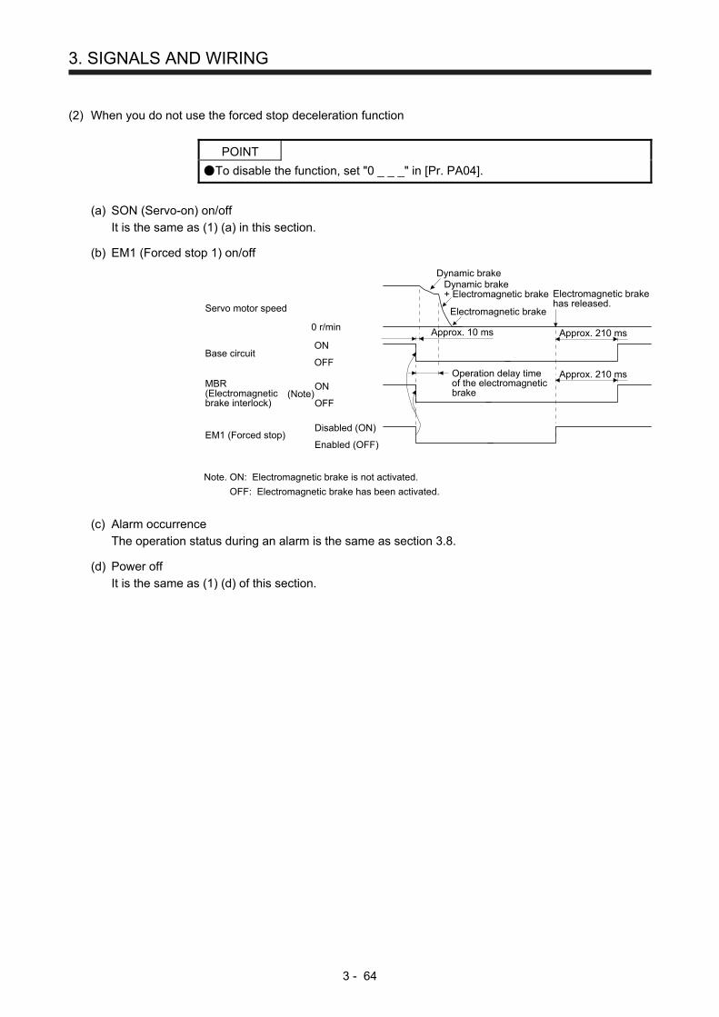
3. SIGNALS AND WIRING
3 - 64
(2) When you do not use the forced stop deceleration function
POINT
To disable the function, set "0 _ _ _" in [Pr. PA04].
(a) SON (Servo-on) on/off
It is the same as (1) (a) in this section.
(b) EM1 (Forced stop 1) on/off
Dynamic brakeDynamic brake+ Electromagnetic brake
Electromagnetic brake
MBR(Electromagneticbrake interlock)
Operation delay timeof the electromagneticbrake
Approx. 210 ms
Approx. 210 ms
Electromagnetic brakehas released.
(Note)ON
OFF
Base circuitON
OFF
Servo motor speed
EM1 (Forced stop)Disabled (ON)
Enabled (OFF)
0 r/min Approx. 10 ms
Note. ON: Electromagnetic brake is not activated.
OFF: Electromagnetic brake has been activated.
(c) Alarm occurrence
The operation status during an alarm is the same as section 3.8.
(d) Power off
It is the same as (1) (d) of this section.
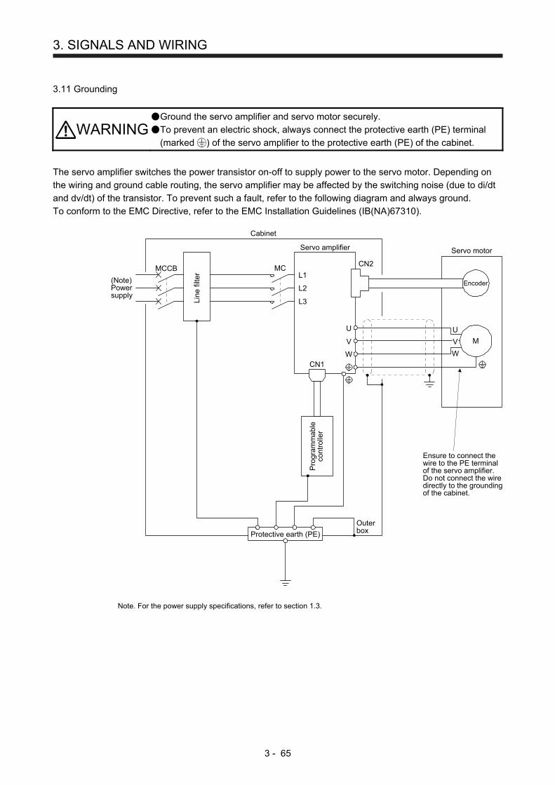
3. SIGNALS AND WIRING
3 - 65
3.11 Grounding
WARNING Ground the servo amplifier and servo motor securely.
To prevent an electric shock, always connect the protective earth (PE) terminal
(marked ) of the servo amplifier to the protective earth (PE) of the cabinet.
The servo amplifier switches the power transistor on-off to supply power to the servo motor. Depending on
the wiring and ground cable routing, the servo amplifier may be affected by the switching noise (due to di/dt
and dv/dt) of the transistor. To prevent such a fault, refer to the following diagram and always ground.
To conform to the EMC Directive, refer to the EMC Installation Guidelines (IB(NA)67310).
Ensure to connect thewire to the PE terminalof the servo amplifier.Do not connect the wiredirectly to the groundingof the cabinet.
Line
filte
r
(Note)Powersupply
V
U
Cabinet
Servo motor
M
U
V
WW
Encoder
CN2
Servo amplifier
L1
L2
L3
CN1
Protective earth (PE)
Outerbox
MCMCCB
Pro
gram
mab
leco
ntro
ller
Note. For the power supply specifications, refer to section 1.3.

3. SIGNALS AND WIRING
3 - 66
MEMO

4. STARTUP
4 - 1
4. STARTUP
WARNING
Do not operate the switches with wet hands. Otherwise, it may cause an electric
shock.
CAUTION
Before starting operation, check the parameters. Improper settings may cause
some machines to operate unexpectedly.
The servo amplifier heat sink, regenerative resistor, servo motor, etc. may be hot
while power is on or for some time after power-off. Take safety measures, e.g.
provide covers, to avoid accidentally touching the parts (cables, etc.) by hand.
During operation, never touch the rotor of the servo motor. Otherwise, it may
cause injury.
4.1 Switching power on for the first time
When switching power on for the first time, follow this section to make a startup.
4.1.1 Startup procedure
Wiring check
Parameter setting
Test operation of the servo motoralone in test operation mode
Test operation of the servo motoralone by commands
Test operation with the servo motorand machine connected
Gain adjustment
Actual operation
Stop
Surrounding environment check
Check whether the servo amplifier and servo motor are wired correctly using
visual inspection, DO forced output function (section 4.5.8), etc. (Refer to
section 4.1.2.)
Check the surrounding environment of the servo amplifier and servo motor.
(Refer to section 4.1.3.)
Set the parameters as necessary, such as the used operation mode and
regenerative option selection. (Refer to chapter 5, and sections 4.2.4, 4.3.4,
and 4.4.4.)
For the test operation, with the servo motor disconnected from the machine
and operated at the speed as low as possible, check whether the servo
motor rotates correctly. (Refer to sections 4.2.3, 4.3.3, and 4.4.3.)
For the test operation with the servo motor disconnected from the machine
and operated at the speed as low as possible, give commands to the servo
amplifier and check whether the servo motor rotates correctly.
After connecting the servo motor with the machine, check machine motions
with sending operation commands from the controller.
Make gain adjustment to optimize the machine motions. (Refer to chapter 6.)
Stop giving commands and stop operation. Other conditions that stop the
servo motor are mentioned in sections 4.2.2, 4.3.2, and 4.4.2.
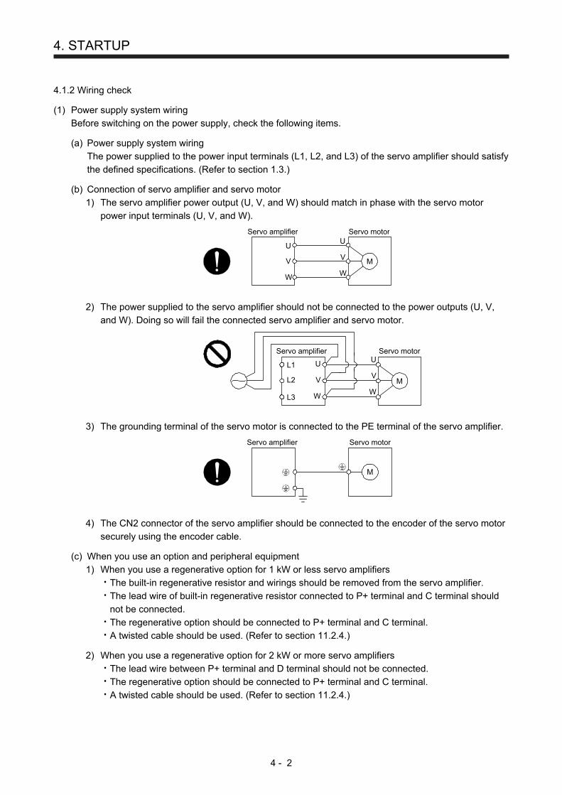
4. STARTUP
4 - 2
4.1.2 Wiring check
(1) Power supply system wiring
Before switching on the power supply, check the following items.
(a) Power supply system wiring
The power supplied to the power input terminals (L1, L2, and L3) of the servo amplifier should satisfy
the defined specifications. (Refer to section 1.3.)
(b) Connection of servo amplifier and servo motor
1) The servo amplifier power output (U, V, and W) should match in phase with the servo motor
power input terminals (U, V, and W).
Servo amplifier Servo motor
M
U
V
W
U
V
W
2) The power supplied to the servo amplifier should not be connected to the power outputs (U, V,
and W). Doing so will fail the connected servo amplifier and servo motor.
Servo amplifier Servo motor
M
U
V
W
U
V
W
L1
L2
L3
3) The grounding terminal of the servo motor is connected to the PE terminal of the servo amplifier.
Servo amplifier Servo motor
M
4) The CN2 connector of the servo amplifier should be connected to the encoder of the servo motor
securely using the encoder cable.
(c) When you use an option and peripheral equipment
1) When you use a regenerative option for 1 kW or less servo amplifiers
The built-in regenerative resistor and wirings should be removed from the servo amplifier.
The lead wire of built-in regenerative resistor connected to P+ terminal and C terminal should
not be connected.
The regenerative option should be connected to P+ terminal and C terminal.
A twisted cable should be used. (Refer to section 11.2.4.)
2) When you use a regenerative option for 2 kW or more servo amplifiers
The lead wire between P+ terminal and D terminal should not be connected.
The regenerative option should be connected to P+ terminal and C terminal.
A twisted cable should be used. (Refer to section 11.2.4.)

4. STARTUP
4 - 3
(2) I/O signal wiring
(a) The I/O signals should be connected correctly.
Use DO forced output to forcibly turn on/off the pins of the CN1 connector. This function can be used
to perform a wiring check. Switch off SON (Servo-on) to enable the function.
Refer to section 3.2 for details of I/O signal connection.
(b) A voltage exceeding 24 V DC is not applied to the pins of the CN1 connector.
(c) Between Plate and DOCOM of the CN1 connector should not be shorted.
Servo amplifier
DOCOM
Plate
CN1
4.1.3 Surrounding environment
(1) Cable routing
(a) The wiring cables should not be stressed.
(b) The encoder cable should not be used in excess of its bending life. (Refer to section 10.4.)
(c) The connector of the servo motor should not be stressed.
(2) Environment
Signal cables and power cables are not shorted by wire offcuts, metallic dust or the like.
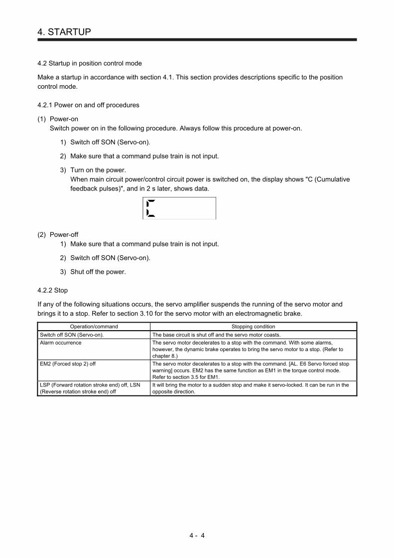
4. STARTUP
4 - 4
4.2 Startup in position control mode
Make a startup in accordance with section 4.1. This section provides descriptions specific to the position
control mode.
4.2.1 Power on and off procedures
(1) Power-on
Switch power on in the following procedure. Always follow this procedure at power-on.
1) Switch off SON (Servo-on).
2) Make sure that a command pulse train is not input.
3) Turn on the power.
When main circuit power/control circuit power is switched on, the display shows "C (Cumulative
feedback pulses)", and in 2 s later, shows data.
(2) Power-off
1) Make sure that a command pulse train is not input.
2) Switch off SON (Servo-on).
3) Shut off the power.
4.2.2 Stop
If any of the following situations occurs, the servo amplifier suspends the running of the servo motor and
brings it to a stop. Refer to section 3.10 for the servo motor with an electromagnetic brake.
Operation/command Stopping condition
Switch off SON (Servo-on). The base circuit is shut off and the servo motor coasts.
Alarm occurrence The servo motor decelerates to a stop with the command. With some alarms, however, the dynamic brake operates to bring the servo motor to a stop. (Refer to chapter 8.)
EM2 (Forced stop 2) off The servo motor decelerates to a stop with the command. [AL. E6 Servo forced stop warning] occurs. EM2 has the same function as EM1 in the torque control mode. Refer to section 3.5 for EM1.
LSP (Forward rotation stroke end) off, LSN (Reverse rotation stroke end) off
It will bring the motor to a sudden stop and make it servo-locked. It can be run in the opposite direction.
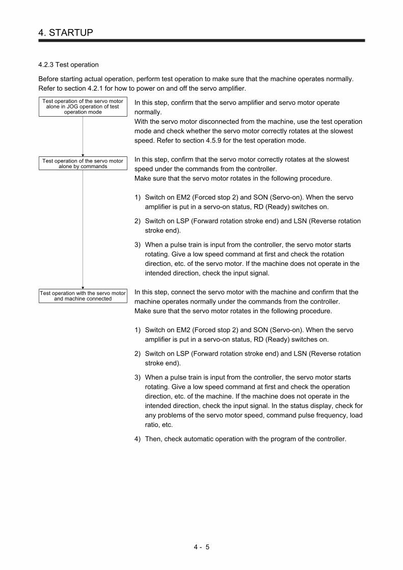
4. STARTUP
4 - 5
4.2.3 Test operation
Before starting actual operation, perform test operation to make sure that the machine operates normally.
Refer to section 4.2.1 for how to power on and off the servo amplifier.
Test operation of the servo motoralone in JOG operation of test
operation mode
Test operation of the servo motoralone by commands
Test operation with the servo motorand machine connected
In this step, confirm that the servo amplifier and servo motor operate
normally.
With the servo motor disconnected from the machine, use the test operation
mode and check whether the servo motor correctly rotates at the slowest
speed. Refer to section 4.5.9 for the test operation mode.
In this step, confirm that the servo motor correctly rotates at the slowest
speed under the commands from the controller.
Make sure that the servo motor rotates in the following procedure.
1) Switch on EM2 (Forced stop 2) and SON (Servo-on). When the servo
amplifier is put in a servo-on status, RD (Ready) switches on. 2) Switch on LSP (Forward rotation stroke end) and LSN (Reverse rotation
stroke end). 3) When a pulse train is input from the controller, the servo motor starts
rotating. Give a low speed command at first and check the rotation
direction, etc. of the servo motor. If the machine does not operate in the
intended direction, check the input signal.
In this step, connect the servo motor with the machine and confirm that the
machine operates normally under the commands from the controller.
Make sure that the servo motor rotates in the following procedure.
1) Switch on EM2 (Forced stop 2) and SON (Servo-on). When the servo
amplifier is put in a servo-on status, RD (Ready) switches on. 2) Switch on LSP (Forward rotation stroke end) and LSN (Reverse rotation
stroke end). 3) When a pulse train is input from the controller, the servo motor starts
rotating. Give a low speed command at first and check the operation
direction, etc. of the machine. If the machine does not operate in the
intended direction, check the input signal. In the status display, check for
any problems of the servo motor speed, command pulse frequency, load
ratio, etc. 4) Then, check automatic operation with the program of the controller.
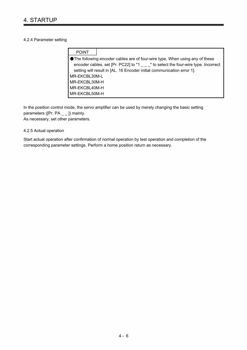
4. STARTUP
4 - 6
4.2.4 Parameter setting
POINT
The following encoder cables are of four-wire type. When using any of these
encoder cables, set [Pr. PC22] to "1 _ _ _" to select the four-wire type. Incorrect
setting will result in [AL. 16 Encoder initial communication error 1].
MR-EKCBL30M-L
MR-EKCBL30M-H
MR-EKCBL40M-H
MR-EKCBL50M-H
In the position control mode, the servo amplifier can be used by merely changing the basic setting
parameters ([Pr. PA _ _ ]) mainly.
As necessary, set other parameters.
4.2.5 Actual operation
Start actual operation after confirmation of normal operation by test operation and completion of the
corresponding parameter settings. Perform a home position return as necessary.

4. STARTUP
4 - 7
4.2.6 Trouble at start-up
CAUTION Never make a drastic adjustment or change to the parameter values as doing so
will make the operation unstable.
POINT
Using the optional MR Configurator2, you can refer to reason for rotation failure,
etc.
The following faults may occur at start-up. If any of such faults occurs, take the corresponding action.
(1) Troubleshooting
No. Start-up sequence Fault Investigation Possible cause Reference
1 Power on 7-segment LED is not lit. 7-segment LED flickers.
Not improved even if CN1 and CN2 connectors are disconnected.
1. Power supply voltage fault 2. The servo amplifier is
malfunctioning.
Improved when CN1 connector is disconnected.
Power supply of CN1 cabling is shorted.
Improved when CN2 connector is disconnected.
1. Power supply of encoder cabling is shorted.
2. Encoder is malfunctioning.
Alarm occurs. Refer to chapter 8 and remove cause. Chapter 8
2 Switch on SON (Servo-on).
Alarm occurs. Refer to chapter 8 and remove cause. Chapter 8
Servo motor shaft is not servo-locked. (Servo motor shaft is free.)
1. Check the display to see if the servo amplifier is ready to operate.
2. Check the external I/O signal indication (section 4.5.7) to see if SON (Servo-on) is on.
1. SON (Servo-on) is not input. (wiring mistake)
2. 24 V DC power is not supplied to DICOM.
Section 4.5.7
3 Input command pulse (test operation).
Servo motor does not rotate.
Check the cumulative command pulse on the status display (section 4.5.3).
1. Wiring mistake (a) For open collector pulse
train input, 24 V DC power is not supplied to OPC.
(b) LSP and LSN are not on. 2. Pulse is not input from the
controller.
Section 4.5.3
Mistake in setting of [Pr. PA13]. Chapter 5 Servo motor run in
reverse direction. 1. Mistake in wiring to controller. 2. Mistake in setting of [Pr.
PA14].
4 Gain adjustment Rotation ripples (speed fluctuations) are large at low speed.
Make gain adjustment in the following procedure. 1. Increase the auto tuning
response level. 2. Repeat acceleration and
deceleration three times to complete auto tuning.
Gain adjustment fault Chapter 6
Large load inertia moment causes the servo motor shaft to oscillate side to side.
If the servo motor may be driven with safety, repeat acceleration and deceleration three times to complete auto tuning.
Gain adjustment fault Chapter 6
5 Cyclic operation Position shift occurs Confirm the cumulative command pulses, cumulative feedback pulses and actual servo motor position.
Pulse counting error, etc. due to noise.
(2) of this
section
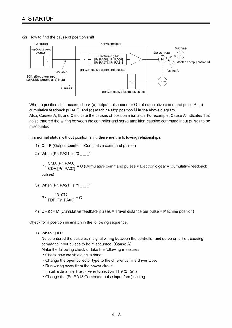
4. STARTUP
4 - 8
(2) How to find the cause of position shift
Encoder
Q P
C
M
L
(b) Cumulative command pulses
(c) Cumulative feedback pulses
(d) Machine stop position M
Cause B
(a) Output pulse counter
Cause A
SON (Servo-on) inputLSP/LSN (Stroke end) input
Servo amplifierController
Servo motor
Machine
Electronic gear[Pr.PA05], [Pr.PA06],[Pr.PA07], [Pr.PA21]
Cause C
When a position shift occurs, check (a) output pulse counter Q, (b) cumulative command pulse P, (c)
cumulative feedback pulse C, and (d) machine stop position M in the above diagram.
Also, Causes A, B, and C indicate the causes of position mismatch. For example, Cause A indicates that
noise entered the wiring between the controller and servo amplifier, causing command input pulses to be
miscounted.
In a normal status without position shift, there are the following relationships.
1) Q = P (Output counter = Cumulative command pulses)
2) When [Pr. PA21] is "0 _ _ _"
P • CMX [Pr. PA06]CDV [Pr. PA07]
= C (Cumulative command pulses × Electronic gear = Cumulative feedback
pulses)
3) When [Pr. PA21] is "1 _ _ _"
P • 131072
FBP [Pr. PA05] = C
4) C • ∆ℓ = M (Cumulative feedback pulses × Travel distance per pulse = Machine position)
Check for a position mismatch in the following sequence.
1) When Q ≠ P
Noise entered the pulse train signal wiring between the controller and servo amplifier, causing command input pulses to be miscounted. (Cause A) Make the following check or take the following measures.
Check how the shielding is done. Change the open collector type to the differential line driver type. Run wiring away from the power circuit. Install a data line filter. (Refer to section 11.9 (2) (a).) Change the [Pr. PA13 Command pulse input form] setting.
4. STARTUP
4 - 9
2) When P • CMXCDV
≠ C
During operation, SON (Servo-on), LSP (Forward rotation stroke end), or LSN (Reverse rotation
stroke end) was switched off; or CR (Clear) or RES (Reset) was switched on. (Cause C)
3) When C • ∆ℓ ≠ M
Mechanical slip occurred between the servo motor and machine. (Cause B)
4.3 Startup in speed control mode
Make a startup in accordance with section 4.1. This section provides the methods specific to the speed
control mode.
4.3.1 Power on and off procedures
(1) Power-on
Switch power on in the following procedure. Always follow this procedure at power-on.
1) Switch off SON (Servo-on).
2) Make sure that ST1 (Forward rotation start) and ST2 (Reverse rotation start) are off.
3) Turn on the power.
When main circuit power/control circuit power is switched on, the display shows "r (Servo motor
speed)", and in 2 s later, shows data.
(2) Power-off
1) Switch off ST1 (Forward rotation start) and ST2 (Reverse rotation start).
2) Switch off SON (Servo-on).
3) Shut off the power.
4.3.2 Stop
If any of the following situations occurs, the servo amplifier suspends the running of the servo motor and
brings it to a stop.
Refer to section 3.10 for the servo motor with an electromagnetic brake.
Operation/command Stopping condition
Switch off SON (Servo-on). The base circuit is shut off and the servo motor coasts.
Alarm occurrence The servo motor decelerates to a stop with the command. With some alarms, however, the dynamic brake operates to bring the servo motor to a stop. (Refer to chapter 8.)
EM2 (Forced stop 2) off The servo motor decelerates to a stop with the command. [AL. E6 Servo forced stop warning] occurs. EM2 has the same function as EM1 in the torque control mode. Refer to section 3.5 for EM1.
LSP (Forward rotation stroke end) off, LSN (Reverse rotation stroke end) off
It will bring the motor to a sudden stop and make it servo-locked. It can be run in the opposite direction.
Simultaneous on or off of ST1 (Forward rotation start) and ST2 (Reverse rotation start)
The servo motor is decelerated to a stop.
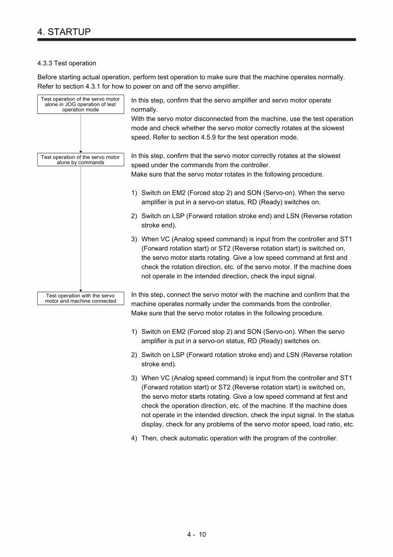
4. STARTUP
4 - 10
4.3.3 Test operation
Before starting actual operation, perform test operation to make sure that the machine operates normally.
Refer to section 4.3.1 for how to power on and off the servo amplifier.
Test operation of the servo motoralone in JOG operation of test
operation mode
Test operation of the servo motoralone by commands
Test operation with the servomotor and machine connected
In this step, confirm that the servo amplifier and servo motor operate
normally.
With the servo motor disconnected from the machine, use the test operation
mode and check whether the servo motor correctly rotates at the slowest
speed. Refer to section 4.5.9 for the test operation mode.
In this step, confirm that the servo motor correctly rotates at the slowest
speed under the commands from the controller.
Make sure that the servo motor rotates in the following procedure.
1) Switch on EM2 (Forced stop 2) and SON (Servo-on). When the servo
amplifier is put in a servo-on status, RD (Ready) switches on. 2) Switch on LSP (Forward rotation stroke end) and LSN (Reverse rotation
stroke end). 3) When VC (Analog speed command) is input from the controller and ST1
(Forward rotation start) or ST2 (Reverse rotation start) is switched on,
the servo motor starts rotating. Give a low speed command at first and
check the rotation direction, etc. of the servo motor. If the machine does
not operate in the intended direction, check the input signal.
In this step, connect the servo motor with the machine and confirm that the
machine operates normally under the commands from the controller.
Make sure that the servo motor rotates in the following procedure.
1) Switch on EM2 (Forced stop 2) and SON (Servo-on). When the servo
amplifier is put in a servo-on status, RD (Ready) switches on. 2) Switch on LSP (Forward rotation stroke end) and LSN (Reverse rotation
stroke end). 3) When VC (Analog speed command) is input from the controller and ST1
(Forward rotation start) or ST2 (Reverse rotation start) is switched on,
the servo motor starts rotating. Give a low speed command at first and
check the operation direction, etc. of the machine. If the machine does
not operate in the intended direction, check the input signal. In the status
display, check for any problems of the servo motor speed, load ratio, etc. 4) Then, check automatic operation with the program of the controller.

4. STARTUP
4 - 11
4.3.4 Parameter setting
POINT
The following encoder cables are of four-wire type. When using any of these
encoder cables, set [Pr. PC22] to "1 _ _ _" to select the four-wire type. Incorrect
setting will result in [AL. 16 Encoder initial communication error 1].
MR-EKCBL30M-L
MR-EKCBL30M-H
MR-EKCBL40M-H
MR-EKCBL50M-H
When using this servo in the speed control mode, change [Pr. PA01] setting to select the speed control
mode. In the speed control mode, the servo can be used by merely changing the basic setting parameters
([Pr. PA _ _ ]) and extension setting parameters ([Pr. PC _ _ ]) mainly.
As necessary, set other parameters.
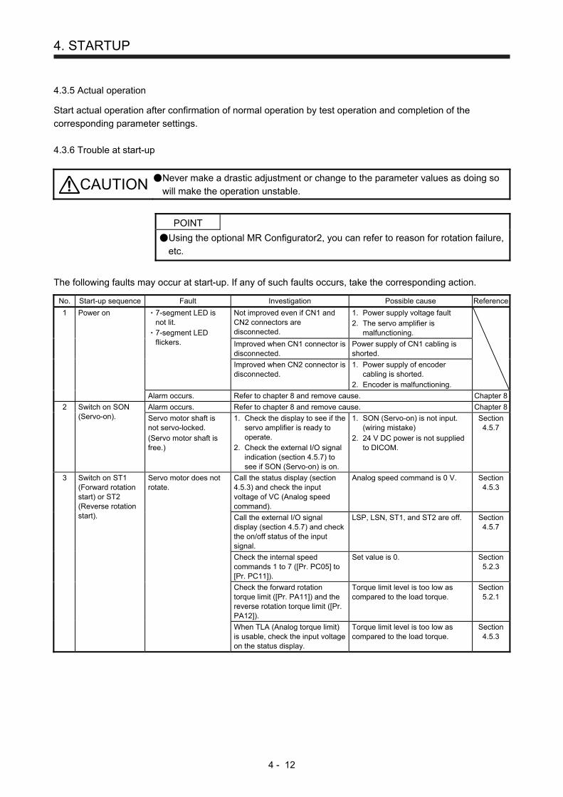
4. STARTUP
4 - 12
4.3.5 Actual operation
Start actual operation after confirmation of normal operation by test operation and completion of the
corresponding parameter settings.
4.3.6 Trouble at start-up
CAUTION Never make a drastic adjustment or change to the parameter values as doing so
will make the operation unstable.
POINT
Using the optional MR Configurator2, you can refer to reason for rotation failure,
etc.
The following faults may occur at start-up. If any of such faults occurs, take the corresponding action.
No. Start-up sequence Fault Investigation Possible cause Reference
1 Power on 7-segment LED is not lit. 7-segment LED flickers.
Not improved even if CN1 and CN2 connectors are disconnected.
1. Power supply voltage fault 2. The servo amplifier is
malfunctioning.
Improved when CN1 connector is disconnected.
Power supply of CN1 cabling is shorted.
Improved when CN2 connector is disconnected.
1. Power supply of encoder cabling is shorted.
2. Encoder is malfunctioning.
Alarm occurs. Refer to chapter 8 and remove cause. Chapter 8
2 Switch on SON (Servo-on).
Alarm occurs. Refer to chapter 8 and remove cause. Chapter 8
Servo motor shaft is not servo-locked. (Servo motor shaft is free.)
1. Check the display to see if the servo amplifier is ready to operate.
2. Check the external I/O signal indication (section 4.5.7) to see if SON (Servo-on) is on.
1. SON (Servo-on) is not input. (wiring mistake)
2. 24 V DC power is not supplied to DICOM.
Section 4.5.7
3 Switch on ST1 (Forward rotation start) or ST2 (Reverse rotation start).
Servo motor does not rotate.
Call the status display (section 4.5.3) and check the input voltage of VC (Analog speed command).
Analog speed command is 0 V. Section 4.5.3
Call the external I/O signal display (section 4.5.7) and check the on/off status of the input signal.
LSP, LSN, ST1, and ST2 are off. Section 4.5.7
Check the internal speed commands 1 to 7 ([Pr. PC05] to [Pr. PC11]).
Set value is 0. Section 5.2.3
Check the forward rotation torque limit ([Pr. PA11]) and the reverse rotation torque limit ([Pr. PA12]).
Torque limit level is too low as compared to the load torque.
Section 5.2.1
When TLA (Analog torque limit) is usable, check the input voltage on the status display.
Torque limit level is too low as compared to the load torque.
Section 4.5.3

4. STARTUP
4 - 13
No. Start-up sequence Fault Investigation Possible cause Reference
4 Gain adjustment Rotation ripples (speed fluctuations) are large at low speed.
Make gain adjustment in the following procedure. 1. Increase the auto tuning
response level. 2. Repeat acceleration and
deceleration three times to complete auto tuning.
Gain adjustment fault Chapter 6
Large load inertia moment causes the servo motor shaft to oscillate side to side.
If the servo motor may be driven with safety, repeat acceleration and deceleration three times to complete auto tuning.
Gain adjustment fault Chapter 6
4.4 Startup in torque control mode
Make a startup in accordance with section 4.1. This section provides the methods specific to the torque
control mode.
4.4.1 Power on and off procedures
(1) Power-on
Switch power on in the following procedure. Always follow this procedure at power-on.
1) Switch off SON (Servo-on).
2) Make sure that RS1 (Forward rotation selection) and RS2 (Reverse rotation selection) are off.
3) Turn on the power.
Data is displayed in 2 s after "U" (Analog torque command) is displayed.
(2) Power-off
1) Switch off RS1 (Forward rotation selection) or RS2 (Reverse rotation selection).
2) Switch off SON (Servo-on).
3) Shut off the power.
4.4.2 Stop
If any of the following situations occurs, the servo amplifier suspends the running of the servo motor and
brings it to a stop. Refer to section 3.10 for the servo motor with an electromagnetic brake.
Operation/command Stopping condition
Switch off SON (Servo-on). The base circuit is shut off and the servo motor coasts.
Alarm occurrence The servo motor decelerates to a stop with the command. With some alarms, however, the dynamic brake operates to bring the servo motor to a stop. (Refer to chapter 8.)
EM2 (Forced stop 2) off This stops the servo motor with the dynamic brake. [AL. E6 Servo forced stop warning] occurs. EM2 has the same function as EM1 in the torque control mode. Refer to section 3.5 for EM1.
Simultaneous on or off of RS1 (Forward rotation selection) and RS2 (Reverse rotation selection)
The servo motor coasts.
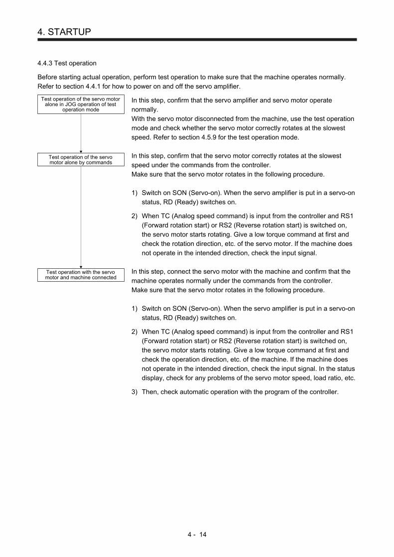
4. STARTUP
4 - 14
4.4.3 Test operation
Before starting actual operation, perform test operation to make sure that the machine operates normally.
Refer to section 4.4.1 for how to power on and off the servo amplifier.
Test operation of the servo motoralone in JOG operation of test
operation mode
Test operation of the servomotor alone by commands
Test operation with the servomotor and machine connected
In this step, confirm that the servo amplifier and servo motor operate
normally.
With the servo motor disconnected from the machine, use the test operation
mode and check whether the servo motor correctly rotates at the slowest
speed. Refer to section 4.5.9 for the test operation mode.
In this step, confirm that the servo motor correctly rotates at the slowest
speed under the commands from the controller.
Make sure that the servo motor rotates in the following procedure.
1) Switch on SON (Servo-on). When the servo amplifier is put in a servo-on
status, RD (Ready) switches on. 2) When TC (Analog speed command) is input from the controller and RS1
(Forward rotation start) or RS2 (Reverse rotation start) is switched on,
the servo motor starts rotating. Give a low torque command at first and
check the rotation direction, etc. of the servo motor. If the machine does
not operate in the intended direction, check the input signal.
In this step, connect the servo motor with the machine and confirm that the
machine operates normally under the commands from the controller.
Make sure that the servo motor rotates in the following procedure.
1) Switch on SON (Servo-on). When the servo amplifier is put in a servo-on
status, RD (Ready) switches on. 2) When TC (Analog speed command) is input from the controller and RS1
(Forward rotation start) or RS2 (Reverse rotation start) is switched on,
the servo motor starts rotating. Give a low torque command at first and
check the operation direction, etc. of the machine. If the machine does
not operate in the intended direction, check the input signal. In the status
display, check for any problems of the servo motor speed, load ratio, etc. 3) Then, check automatic operation with the program of the controller.
4. STARTUP
4 - 15
4.4.4 Parameter setting
POINT
The following encoder cables are of four-wire type. When using any of these
encoder cables, set [Pr. PC22] to "1 _ _ _" to select the four-wire type. Incorrect
setting will result in [AL. 16 Encoder initial communication error 1].
MR-EKCBL30M-L
MR-EKCBL30M-H
MR-EKCBL40M-H
MR-EKCBL50M-H
When using this servo in the torque control mode, change [Pr. PA01] setting to select the torque control
mode. In the torque control mode, the servo can be used by merely changing the basic setting parameters
([Pr. PA _ _ ]) and extension setting parameters ([Pr. PC _ _ ]) mainly.
As necessary, set other parameters.
4.4.5 Actual operation
Start actual operation after confirmation of normal operation by test operation and completion of the
corresponding parameter settings.

4. STARTUP
4 - 16
4.4.6 Trouble at start-up
CAUTION Never make a drastic adjustment or change to the parameter values as doing so
will make the motion unstable.
POINT
Using the optional MR Configurator2, you can refer to reason for rotation failure,
etc.
The following faults may occur at start-up. If any of such faults occurs, take the corresponding action.
No. Start-up sequence Fault Investigation Possible cause Reference
1 Power on 7-segment LED is not lit. 7-segment LED flickers.
Not improved even if CN1 and CN2 connectors are disconnected.
1. Power supply voltage fault 2. The servo amplifier is
malfunctioning.
Improved when CN1 connector is disconnected.
Power supply of CN1 cabling is shorted.
Improved when CN2 connector is disconnected.
1. Power supply of encoder cabling is shorted.
2. Encoder is malfunctioning.
Alarm occurs. Refer to chapter 8 and remove cause. Chapter 8
2 Switch on SON (Servo-on).
Alarm occurs. Refer to chapter 8 and remove cause. Chapter 8
Servo motor shaft is free.
Call the external I/O signal display (section 4.5.7) and check the on/off status of the input signal.
1. SON (Servo-on) is not input. (wiring mistake)
2. 24 V DC power is not supplied to DICOM.
Section 4.5.7
3 Switch on RS1 (Forward rotation start) or RS2 (Reverse rotation start).
Servo motor does not rotate.
Call the status display (section 4.5.3) and check the input voltage of TC (Analog torque command).
Analog torque command is 0 V. Section 4.5.3
Call the external I/O signal display (section 4.5.7) and check the on/off status of the input signal.
RS1 and RS2 are off. Section 4.5.7
Check the internal speed limit 1 to 7 ([Pr. PC05] to [Pr. PC11]).
Set value is 0. Section 5.2.3
Check the analog torque command maximum output ([Pr. PC13]) value.
Torque command level is too low as compared to the load torque.
Section 5.2.3
Check the forward rotation torque limit ([Pr. PA11]) and the reverse rotation torque limit ([Pr. PA12]).
Set value is 0. Section 5.2.1
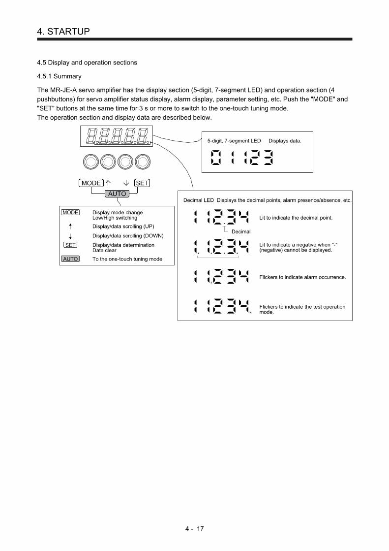
4. STARTUP
4 - 17
4.5 Display and operation sections
4.5.1 Summary
The MR-JE-A servo amplifier has the display section (5-digit, 7-segment LED) and operation section (4
pushbuttons) for servo amplifier status display, alarm display, parameter setting, etc. Push the "MODE" and
"SET" buttons at the same time for 3 s or more to switch to the one-touch tuning mode.
The operation section and display data are described below.
Display mode changeLow/High switching
Decimal LED Displays the decimal points, alarm presence/absence, etc.
Lit to indicate the decimal point.
Decimal
Lit to indicate a negative when "-"(negative) cannot be displayed.
Flickers to indicate alarm occurrence.
Flickers to indicate the test operationmode.
5-digit, 7-segment LED Displays data.
MODE
SET
AUTO
Display/data scrolling (UP)
Display/data scrolling (DOWN)
Display/data determinationData clear
To the one-touch tuning mode
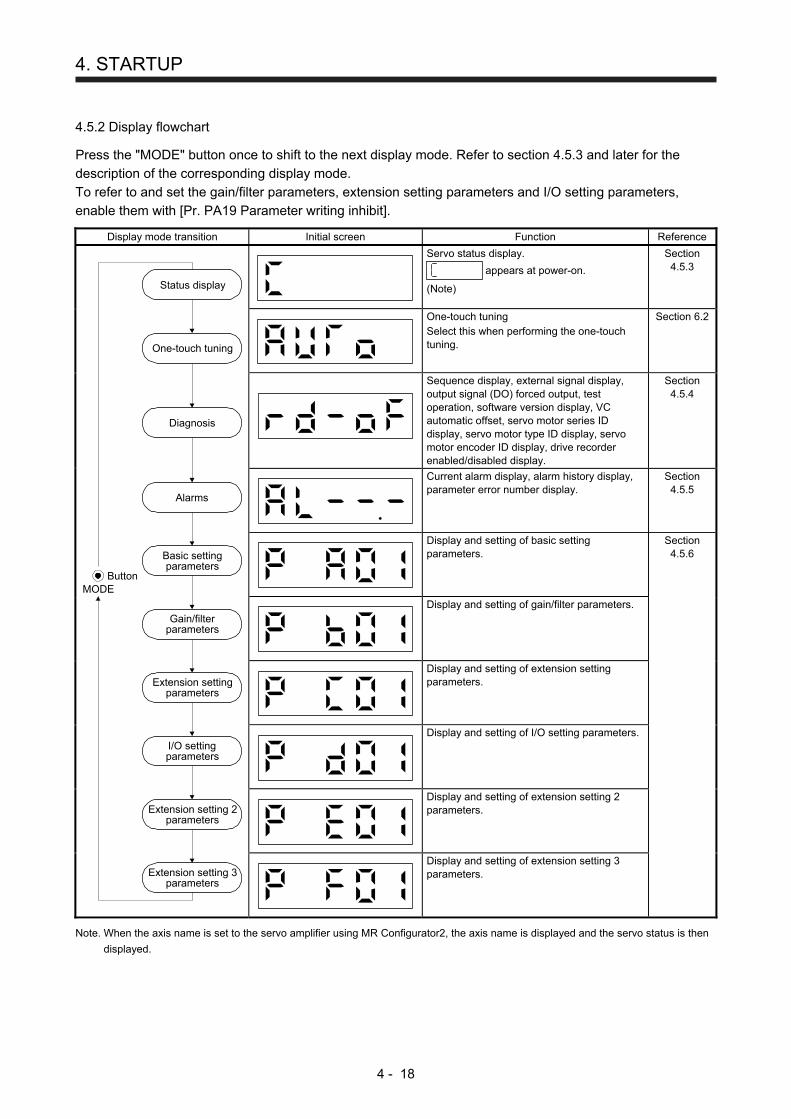
4. STARTUP
4 - 18
4.5.2 Display flowchart
Press the "MODE" button once to shift to the next display mode. Refer to section 4.5.3 and later for the
description of the corresponding display mode.
To refer to and set the gain/filter parameters, extension setting parameters and I/O setting parameters,
enable them with [Pr. PA19 Parameter writing inhibit].
Display mode transition Initial screen Function Reference
Status display
Diagnosis
Alarms
Basic settingparameters
Gain/filterparameters
Extension settingparameters
Extension setting 2parameters
Extension setting 3parameters
I/O settingparameters
ButtonMODE
One-touch tuning
Servo status display.
appears at power-on.
(Note)
Section 4.5.3
One-touch tuning Select this when performing the one-touch tuning.
Section 6.2
Sequence display, external signal display, output signal (DO) forced output, test operation, software version display, VC automatic offset, servo motor series ID display, servo motor type ID display, servo motor encoder ID display, drive recorder enabled/disabled display.
Section 4.5.4
Current alarm display, alarm history display, parameter error number display.
Section 4.5.5
Display and setting of basic setting parameters.
Section 4.5.6
Display and setting of gain/filter parameters.
Display and setting of extension setting parameters.
Display and setting of I/O setting parameters.
Display and setting of extension setting 2 parameters.
Display and setting of extension setting 3 parameters.
Note. When the axis name is set to the servo amplifier using MR Configurator2, the axis name is displayed and the servo status is then
displayed.
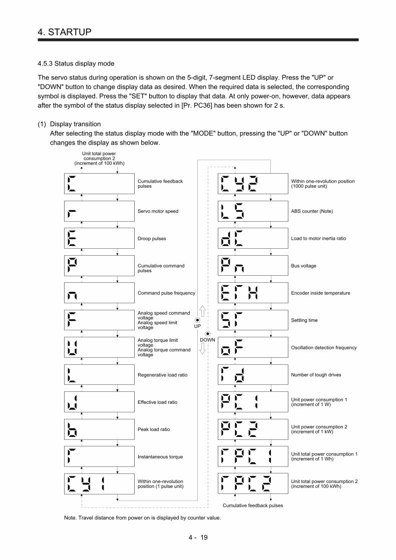
4. STARTUP
4 - 19
4.5.3 Status display mode
The servo status during operation is shown on the 5-digit, 7-segment LED display. Press the "UP" or
"DOWN" button to change display data as desired. When the required data is selected, the corresponding
symbol is displayed. Press the "SET" button to display that data. At only power-on, however, data appears
after the symbol of the status display selected in [Pr. PC36] has been shown for 2 s.
(1) Display transition
After selecting the status display mode with the "MODE" button, pressing the "UP" or "DOWN" button
changes the display as shown below.
Regenerative load ratio
Cumulative feedbackpulses
Effective load ratio
Peak load ratio
Instantaneous torque
Within one-revolutionposition (1 pulse unit)
Servo motor speed
Within one-revolution position(1000 pulse unit)
Droop pulses
Cumulative commandpulses
Load to motor inertia ratio
ABS counter (Note)
Command pulse frequency
Bus voltage
Encoder inside temperature
Settling time
Oscillation detection frequency
Number of tough drives
Unit power consumption 1(increment of 1 W)
Unit total power consumption 1(increment of 1 Wh)
Unit power consumption 2(increment of 1 kW)
Unit total power consumption 2(increment of 100 kWh)
Unit total powerconsumption 2
(increment of 100 kWh)
Cumulative feedback pulses
Analog torque limitvoltageAnalog torque commandvoltage
Analog speed commandvoltageAnalog speed limitvoltage
DOWN
UP
Note. Travel distance from power on is displayed by counter value.

4. STARTUP
4 - 20
(2) Display examples
The following table shows the display examples.
Item Status Displayed data
Servo amplifier display
Servo motor speed
Forward rotation at 2500 r/min
Reverse rotation at 3000 r/min
Reverse rotation is indicated by "- ".
Load to motor inertia ratio 7.00 times
Cumulative feedback pulses
11252 pulses
-12566 pulses Lit
Negative value is indicated by the lit decimal points in the upper four digits.
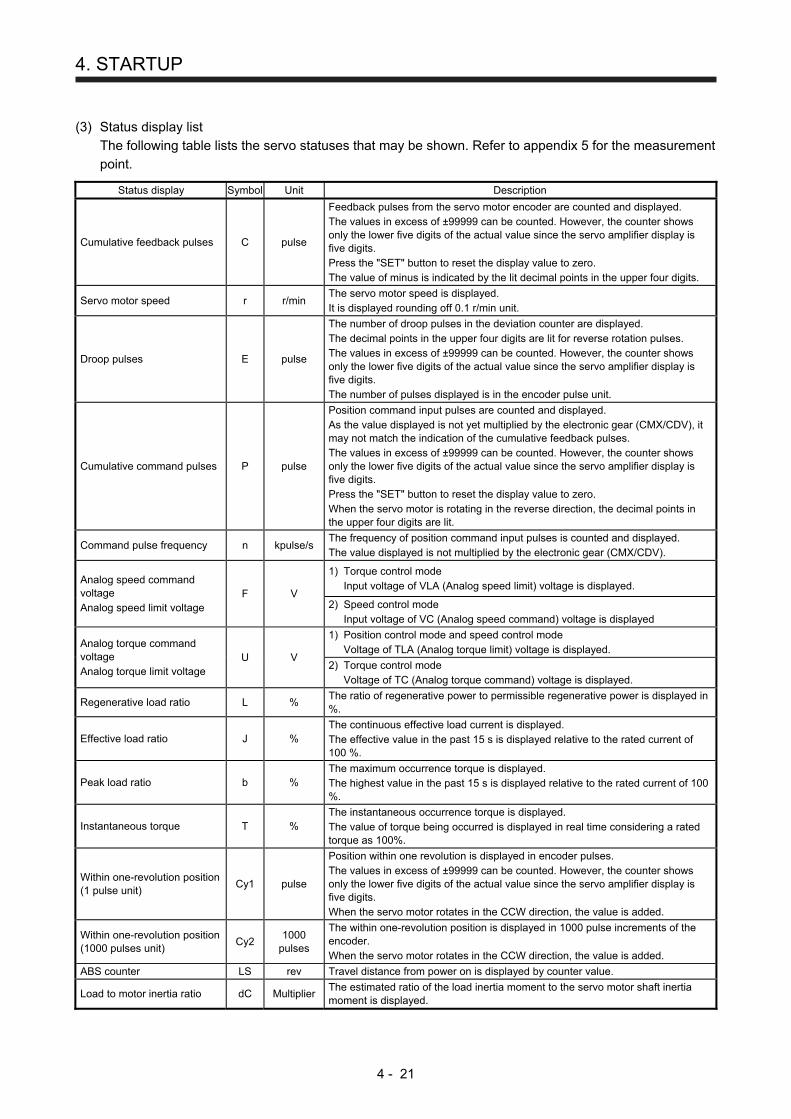
4. STARTUP
4 - 21
(3) Status display list
The following table lists the servo statuses that may be shown. Refer to appendix 5 for the measurement
point.
Status display Symbol Unit Description
Cumulative feedback pulses C pulse
Feedback pulses from the servo motor encoder are counted and displayed. The values in excess of ±99999 can be counted. However, the counter shows only the lower five digits of the actual value since the servo amplifier display is five digits. Press the "SET" button to reset the display value to zero. The value of minus is indicated by the lit decimal points in the upper four digits.
Servo motor speed r r/min The servo motor speed is displayed. It is displayed rounding off 0.1 r/min unit.
Droop pulses E pulse
The number of droop pulses in the deviation counter are displayed. The decimal points in the upper four digits are lit for reverse rotation pulses. The values in excess of ±99999 can be counted. However, the counter shows only the lower five digits of the actual value since the servo amplifier display is five digits. The number of pulses displayed is in the encoder pulse unit.
Cumulative command pulses P pulse
Position command input pulses are counted and displayed. As the value displayed is not yet multiplied by the electronic gear (CMX/CDV), it may not match the indication of the cumulative feedback pulses. The values in excess of ±99999 can be counted. However, the counter shows only the lower five digits of the actual value since the servo amplifier display is five digits. Press the "SET" button to reset the display value to zero. When the servo motor is rotating in the reverse direction, the decimal points in the upper four digits are lit.
Command pulse frequency n kpulse/s The frequency of position command input pulses is counted and displayed. The value displayed is not multiplied by the electronic gear (CMX/CDV).
Analog speed command voltage Analog speed limit voltage
F V
1) Torque control mode Input voltage of VLA (Analog speed limit) voltage is displayed.
2) Speed control mode Input voltage of VC (Analog speed command) voltage is displayed
Analog torque command voltage Analog torque limit voltage
U V
1) Position control mode and speed control mode Voltage of TLA (Analog torque limit) voltage is displayed.
2) Torque control mode Voltage of TC (Analog torque command) voltage is displayed.
Regenerative load ratio L % The ratio of regenerative power to permissible regenerative power is displayed in %.
Effective load ratio J % The continuous effective load current is displayed. The effective value in the past 15 s is displayed relative to the rated current of 100 %.
Peak load ratio b % The maximum occurrence torque is displayed. The highest value in the past 15 s is displayed relative to the rated current of 100 %.
Instantaneous torque T % The instantaneous occurrence torque is displayed. The value of torque being occurred is displayed in real time considering a rated torque as 100%.
Within one-revolution position (1 pulse unit)
Cy1 pulse
Position within one revolution is displayed in encoder pulses. The values in excess of ±99999 can be counted. However, the counter shows only the lower five digits of the actual value since the servo amplifier display is five digits. When the servo motor rotates in the CCW direction, the value is added.
Within one-revolution position (1000 pulses unit)
Cy2 1000
pulses
The within one-revolution position is displayed in 1000 pulse increments of the encoder. When the servo motor rotates in the CCW direction, the value is added.
ABS counter LS rev Travel distance from power on is displayed by counter value.
Load to motor inertia ratio dC Multiplier The estimated ratio of the load inertia moment to the servo motor shaft inertia moment is displayed.

4. STARTUP
4 - 22
Status display Symbol Unit Description
Bus voltage Pn V The voltage of main circuit converter (between P+ and N-) is displayed.
Encoder inside temperature ETh °C Inside temperature of encoder detected by the encoder is displayed.
Settling time ST ms Settling time is displayed. When it exceeds 1000 ms, "1000" will be displayed.
Oscillation detection frequency
oF Hz Frequency at the time of oscillation detection is displayed.
Number of tough drive operations
Td times The number of tough drive functions activated is displayed.
Unit power consumption 1 (increment of 1 W)
PC1 W
Unit power consumption is displayed by increment of 1 W. Positive value indicate power running, and negative value indicate regeneration. The values in excess of ±99999 can be counted. However, the counter shows only the lower five digits of the actual value since the servo amplifier display is five digits.
Unit power consumption 2 (increment of 1 kW)
PC2 kW Unit power consumption is displayed by increment of 1 kW. Positive value indicate power running, and negative value indicate regeneration.
Unit total power consumption 1 (increment of 1 Wh)
TPC1 Wh
Unit total power consumption is displayed by increment of 1 Wh. Positive value is cumulated during power running and negative value during regeneration. The values in excess of ±99999 can be counted. However, the counter shows only the lower five digits of the actual value since the servo amplifier display is five digits.
Unit total power consumption 2 (increment of 100 kWh)
TPC2 100 kWh Unit total power consumption is displayed by increment of 100 kWh. Positive value is cumulated during power running and negative value during regeneration.
(4) Changing the status display screen
The status display item of the servo amplifier display shown at power-on can be changed by changing
[Pr. PC36] settings. The item displayed in the initial status changes with the control mode as follows.
Control mode Status display
Position Cumulative feedback pulses
Position/speed Cumulative feedback pulses/servo motor speed
Speed Servo motor speed
Speed/torque Servo motor speed/analog torque command voltage
Torque Analog torque command voltage
Torque/position Analog torque command voltage/cumulative feedback pulses

4. STARTUP
4 - 23
4.5.4 Diagnostic mode
Name Display Description
Sequence
Not ready Indicates that the servo amplifier is being initialized or an alarm has occurred.
Ready Indicates that the servo was switched on after completion of initialization and the servo amplifier is ready to operate.
Drive recorder enabled/disabled display
Drive recorder enabled When an alarm occurs in the status, the drive recorder will operate and write the status of occurrence.
Drive recorder disabled The drive recorder will not operate on the following conditions. 1. You are using the graph function of MR
Configurator2. 2. You are using the machine analyzer
function. 3. [Pr. PF21] is set to "-1".
External I/O signal display Refer to section 4.5.7.
This Indicates the on/off status of external I/O signal. The upper segments correspond to the input signals and the lower segments to the output signals.
Output signal (DO) forced output
This allows digital output signal to be switched on/off forcibly. For details, refer to section 4.5.8.
Test operation mode
JOG operation
JOG operation can be performed when there is no command from an external controller. For details, refer to section 4.5.9 (2).
Positioning operation
Positioning operation can be performed when there is no command from an external controller. MR Configurator2 is required to perform positioning operation. For details, refer to section 4.5.9 (3).
Motor-less operation
Without connecting the servo motor, this test operation mode enables to output signals and check the status display in response to the input device as if the servo motor is actually running. For details, refer to section 4.5.9 (4).
Machine analyzer operation
Merely connecting the servo amplifier allows the resonance point of the mechanical system to be measured. MR Configurator2 is required to perform machine analyzer operation. Refer to section 11.4 for details.
For manufacturer adjustment
This is for manufacturer adjustment.
For manufacturer adjustment.
This is for manufacturer adjustment.

4. STARTUP
4 - 24
Name Display Description
Software version - Lower
Indicates the version of the software.
Software version - Upper
Indicates the system number of the software.
Automatic VC offset
If offset voltages in the analog circuits inside and outside the servo amplifier cause the servo motor to rotate slowly at VC (Analog speed command) or VLA (Analog speed limit) of 0 V, this function automatically makes zero-adjustment of offset voltages. When using this function, enable the function in the following procedure. When it is enabled, [Pr. PC37] value changes to the automatically adjusted offset voltage. 1) Push "SET" once. 2) Set the number in the first digit to 1 with
"UP". 3) Push "SET". This function cannot be used if the input voltage of VC or VLA is -0.4 V or less, or +0.4 V or more. (Note)
Servo motor series ID
Push the "SET" button to show the series ID of the servo motor currently connected. For indication details, refer to appendix 1 of "HG-KN/HG-SN servo Motor Instruction Manual".
Servo motor type ID
Push the "SET" button to show the type ID of the servo motor currently connected. For indication details, refer to appendix 1 of "HG-KN/HG-SN servo Motor Instruction Manual".
Servo motor encoder ID
Push the "SET" button to show the encoder ID of the servo motor currently connected. For indication details, refer to appendix 1 of "HG-KN/HG-SN servo Motor Instruction Manual".
For manufacturer adjustment
This is for manufacturer adjustment.
For manufacturer adjustment
This is for manufacturer adjustment.
Note. Even if Automatic VC offset is performed and 0 V is input, the servo motor may not completely stop due to an internal error. To
completely stop the servo motor, switch off ST1 or ST2.

4. STARTUP
4 - 25
4.5.5 Alarm mode
The current alarm, past alarm history and parameter error are displayed. The lower 3 digits on the display
indicate the alarm number that has occurred or the parameter number in error.
Name Display Description
Current alarm
Indicates no occurrence of an alarm.
Indicates the occurrence of [AL. 33.1 Main circuit voltage error]. Flickers at alarm occurrence.
Alarm history
Indicates that the last alarm is [AL. 50.1 Thermal overload error 1 during operation].
Indicates the second last alarm is [AL. 33.1 Main circuit voltage error].
Indicates the third last alarm is [AL. 10.1 Voltage drop in the power].
Indicates that there is no tenth alarm in the past.
Indicates that there is no eleventh alarm in the past.
Indicates that there is no twelfth alarm in the past.
Indicates that there is no sixteenth alarm in the past.
Parameter error No.
This indicates no occurrence of [AL. 37 Parameter error].
The data content error of [Pr. PA12 Reverse rotation torque limit].
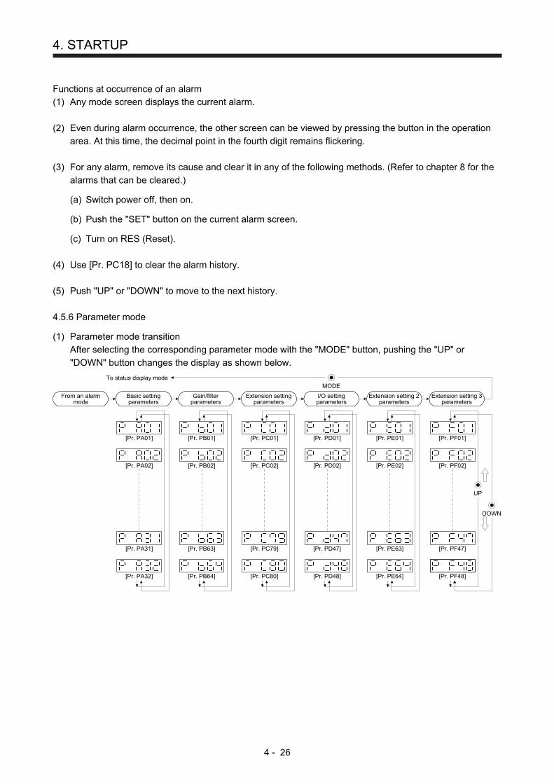
4. STARTUP
4 - 26
Functions at occurrence of an alarm
(1) Any mode screen displays the current alarm.
(2) Even during alarm occurrence, the other screen can be viewed by pressing the button in the operation
area. At this time, the decimal point in the fourth digit remains flickering.
(3) For any alarm, remove its cause and clear it in any of the following methods. (Refer to chapter 8 for the
alarms that can be cleared.)
(a) Switch power off, then on.
(b) Push the "SET" button on the current alarm screen.
(c) Turn on RES (Reset).
(4) Use [Pr. PC18] to clear the alarm history.
(5) Push "UP" or "DOWN" to move to the next history.
4.5.6 Parameter mode
(1) Parameter mode transition
After selecting the corresponding parameter mode with the "MODE" button, pushing the "UP" or
"DOWN" button changes the display as shown below.
[Pr. PB01]
[Pr. PA02]
[Pr. PA01]
I/O settingparameters
[Pr. PD01]
[Pr. PD02]
[Pr. PD47]
[Pr. PD48]
[Pr. PC01]
[Pr. PC02]
[Pr. PC79]
Extension settingparameters
[Pr. PC80]
[Pr. PB02]
[Pr. PB63]
[Pr. PB64]
To status display mode
[Pr. PA31]
Basic settingparameters
[Pr. PA32]
Extension setting 2parameters
[Pr. PE01]
[Pr. PE02]
[Pr. PE63]
[Pr. PE64]
Extension setting 3parameters
[Pr. PF01]
[Pr. PF02]
[Pr. PF47]
[Pr. PF48]
Gain/filterparameters
MODE
UP
DOWN
From an alarmmode
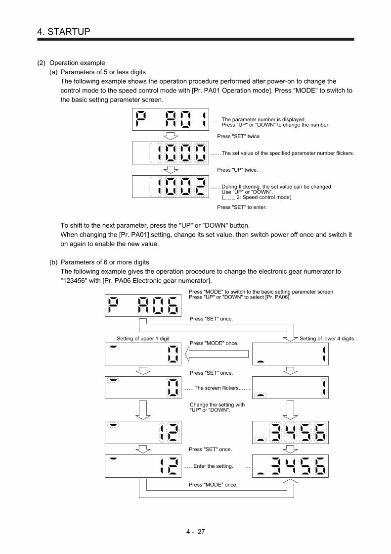
4. STARTUP
4 - 27
(2) Operation example
(a) Parameters of 5 or less digits
The following example shows the operation procedure performed after power-on to change the
control mode to the speed control mode with [Pr. PA01 Operation mode]. Press "MODE" to switch to
the basic setting parameter screen.
The parameter number is displayed.Press "UP" or "DOWN" to change the number.
The set value of the specified parameter number flickers.
Press "SET" twice.
Press "SET" to enter.
Press "UP" twice.
During flickering, the set value can be changed.Use "UP" or "DOWN".(_ _ _ 2: Speed control mode)
……
……
……
To shift to the next parameter, press the "UP" or "DOWN" button.
When changing the [Pr. PA01] setting, change its set value, then switch power off once and switch it
on again to enable the new value.
(b) Parameters of 6 or more digits
The following example gives the operation procedure to change the electronic gear numerator to
"123456" with [Pr. PA06 Electronic gear numerator].
The screen flickers.
Press "MODE" to switch to the basic setting parameter screen.Press "UP" or "DOWN" to select [Pr. PA06].
Press "SET" once.
Press "SET" once.
Setting of upper 1 digit
Change the setting with"UP" or "DOWN".
Press "SET" once.
Enter the setting.
Press "MODE" once.
Press "MODE" once.Setting of lower 4 digits
…… ……
…… …
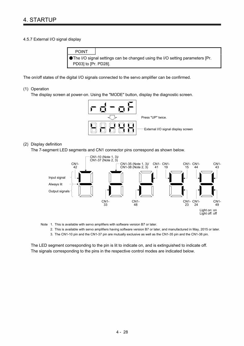
4. STARTUP
4 - 28
4.5.7 External I/O signal display
POINT
The I/O signal settings can be changed using the I/O setting parameters [Pr.
PD03] to [Pr. PD28].
The on/off states of the digital I/O signals connected to the servo amplifier can be confirmed.
(1) Operation
The display screen at power-on. Using the "MODE" button, display the diagnostic screen.
Press "UP" twice.
……External I/O signal display screen
(2) Display definition
The 7-segment LED segments and CN1 connector pins correspond as shown below.
Input signal
Output signals
Always lit
CN1-42
CN1-41
CN1-48
CN1-19
CN1-15
CN1-23
CN1-49
CN1-24
Light on: onLight off: off
CN1-33
CN1-44
CN1-43
CN1-35 (Note 1, 3)/CN1-38 (Note 2, 3)
CN1-10 (Note 1, 3)/CN1-37 (Note 2, 3)
Note 1. This is available with servo amplifiers with software version B7 or later.
2. This is available with servo amplifiers having software version B7 or later, and manufactured in May, 2015 or later.
3. The CN1-10 pin and the CN1-37 pin are mutually exclusive as well as the CN1-35 pin and the CN1-38 pin.
The LED segment corresponding to the pin is lit to indicate on, and is extinguished to indicate off.
The signals corresponding to the pins in the respective control modes are indicated below.
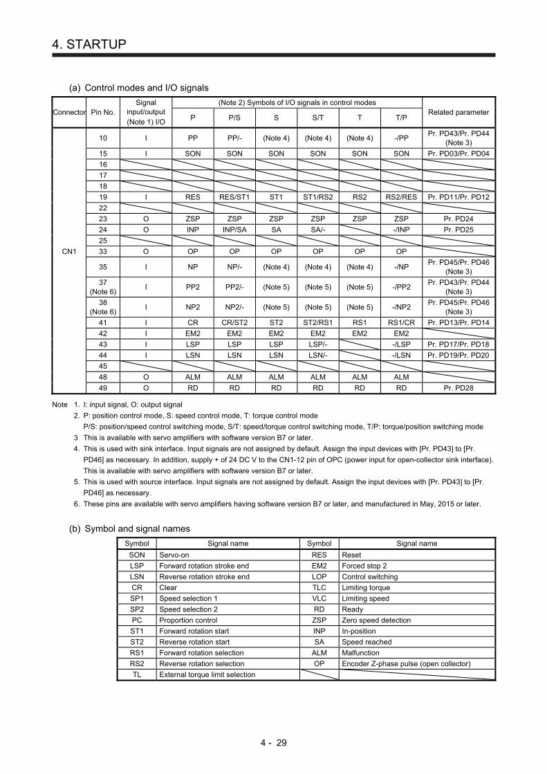
4. STARTUP
4 - 29
(a) Control modes and I/O signals
Connector Pin No. Signal
input/output (Note 1) I/O
(Note 2) Symbols of I/O signals in control modes Related parameter
P P/S S S/T T T/P
10 I PP PP/- (Note 4) (Note 4) (Note 4) -/PP Pr. PD43/Pr. PD44
(Note 3)
15 I SON SON SON SON SON SON Pr. PD03/Pr. PD04
16
17
18
19 I RES RES/ST1 ST1 ST1/RS2 RS2 RS2/RES Pr. PD11/Pr. PD12
22
23 O ZSP ZSP ZSP ZSP ZSP ZSP Pr. PD24
24 O INP INP/SA SA SA/- -/INP Pr. PD25
25
CN1 33 O OP OP OP OP OP OP
35 I NP NP/- (Note 4) (Note 4) (Note 4) -/NP Pr. PD45/Pr. PD46
(Note 3)
37
(Note 6) I PP2 PP2/- (Note 5) (Note 5) (Note 5) -/PP2
Pr. PD43/Pr. PD44 (Note 3)
38
(Note 6) I NP2 NP2/- (Note 5) (Note 5) (Note 5) -/NP2
Pr. PD45/Pr. PD46 (Note 3)
41 I CR CR/ST2 ST2 ST2/RS1 RS1 RS1/CR Pr. PD13/Pr. PD14
42 I EM2 EM2 EM2 EM2 EM2 EM2
43 I LSP LSP LSP LSP/- -/LSP Pr. PD17/Pr. PD18
44 I LSN LSN LSN LSN/- -/LSN Pr. PD19/Pr. PD20
45
48 O ALM ALM ALM ALM ALM ALM
49 O RD RD RD RD RD RD Pr. PD28 Note 1. I: input signal, O: output signal
2. P: position control mode, S: speed control mode, T: torque control mode
P/S: position/speed control switching mode, S/T: speed/torque control switching mode, T/P: torque/position switching mode
3 This is available with servo amplifiers with software version B7 or later.
4. This is used with sink interface. Input signals are not assigned by default. Assign the input devices with [Pr. PD43] to [Pr.
PD46] as necessary. In addition, supply + of 24 DC V to the CN1-12 pin of OPC (power input for open-collector sink interface).
This is available with servo amplifiers with software version B7 or later.
5. This is used with source interface. Input signals are not assigned by default. Assign the input devices with [Pr. PD43] to [Pr.
PD46] as necessary.
6. These pins are available with servo amplifiers having software version B7 or later, and manufactured in May, 2015 or later.
(b) Symbol and signal names
Symbol Signal name Symbol Signal name
SON Servo-on RES Reset
LSP Forward rotation stroke end EM2 Forced stop 2
LSN Reverse rotation stroke end LOP Control switching
CR Clear TLC Limiting torque
SP1 Speed selection 1 VLC Limiting speed
SP2 Speed selection 2 RD Ready
PC Proportion control ZSP Zero speed detection
ST1 Forward rotation start INP In-position
ST2 Reverse rotation start SA Speed reached
RS1 Forward rotation selection ALM Malfunction
RS2 Reverse rotation selection OP Encoder Z-phase pulse (open collector)
TL External torque limit selection

4. STARTUP
4 - 30
(3) Display data at initial values
(a) Position control mode
Light on: onLight off: off
EM2 (CN1-42)
Input signal
Output signals
OP (CN1-33)
ALM (CN1-48)
CR (CN1-41)
RES (CN1-19)
SON (CN1-15)
LSN (CN1-44)
LSP (CN1-43)
RD (CN1-49)
INP (CN1-24)
ZSP (CN1-23)
(b) Speed control mode
Light on: onLight off: off
EM2 (CN1-42)
Input signal
Output signals
OP (CN1-33)
ALM (CN1-48)
ST2 (CN1-41)
ST1 (CN1-19)
SON (CN1-15)
LSN (CN1-44)
LSP (CN1-43)
RD (CN1-49)
SA (CN1-24)
ZSP (CN1-23)
(c) Torque control mode
Light on: onLight off: off
EM2 (CN1-42)
Input signal
Output signals
OP (CN1-33)
ALM (CN1-48)
RS1 (CN1-41)
RS2 (CN1-19)
SON (CN1-15)
RD (CN1-49)
ZSP (CN1-23)
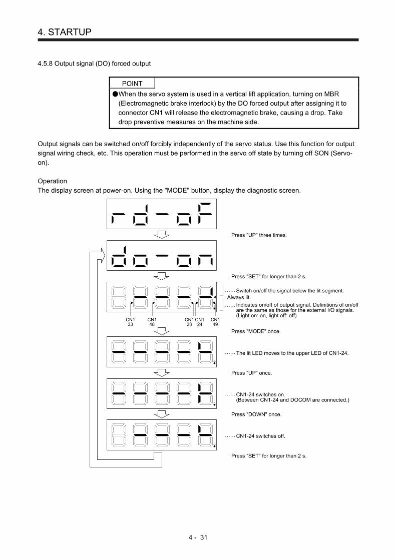
4. STARTUP
4 - 31
4.5.8 Output signal (DO) forced output
POINT
When the servo system is used in a vertical lift application, turning on MBR
(Electromagnetic brake interlock) by the DO forced output after assigning it to
connector CN1 will release the electromagnetic brake, causing a drop. Take
drop preventive measures on the machine side.
Output signals can be switched on/off forcibly independently of the servo status. Use this function for output
signal wiring check, etc. This operation must be performed in the servo off state by turning off SON (Servo-
on).
Operation
The display screen at power-on. Using the "MODE" button, display the diagnostic screen.
……
……
……
……
……
Switch on/off the signal below the lit segment.
Indicates on/off of output signal. Definitions of on/offare the same as those for the external I/O signals.(Light on: on, light off: off)
Press "UP" three times.
Press "SET" for longer than 2 s.
CN133
CN148
CN123
CN124
CN149
Press "MODE" once.
Press "UP" once.
CN1-24 switches on.(Between CN1-24 and DOCOM are connected.)
The lit LED moves to the upper LED of CN1-24.
Press "DOWN" once.
CN1-24 switches off.
Press "SET" for longer than 2 s.
Always lit.
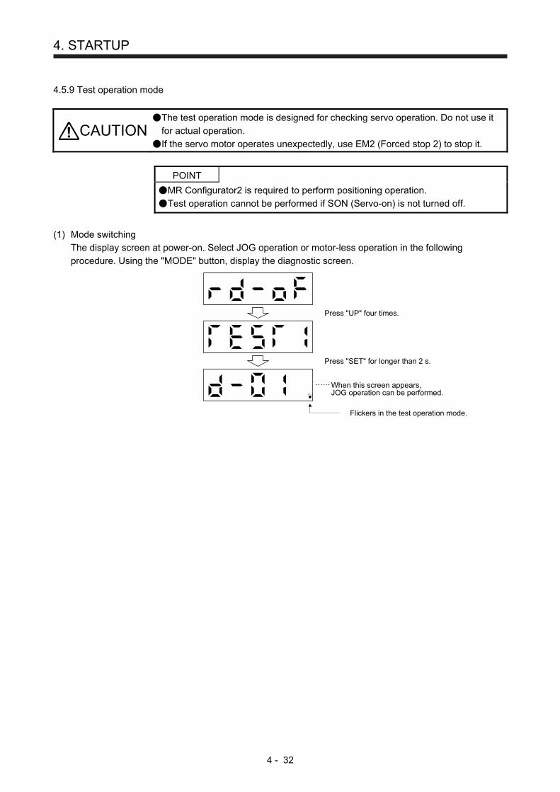
4. STARTUP
4 - 32
4.5.9 Test operation mode
CAUTION The test operation mode is designed for checking servo operation. Do not use it
for actual operation.
If the servo motor operates unexpectedly, use EM2 (Forced stop 2) to stop it.
POINT
MR Configurator2 is required to perform positioning operation.
Test operation cannot be performed if SON (Servo-on) is not turned off.
(1) Mode switching
The display screen at power-on. Select JOG operation or motor-less operation in the following
procedure. Using the "MODE" button, display the diagnostic screen.
Press "UP" four times.
Press "SET" for longer than 2 s.
When this screen appears,JOG operation can be performed.
Flickers in the test operation mode.
……
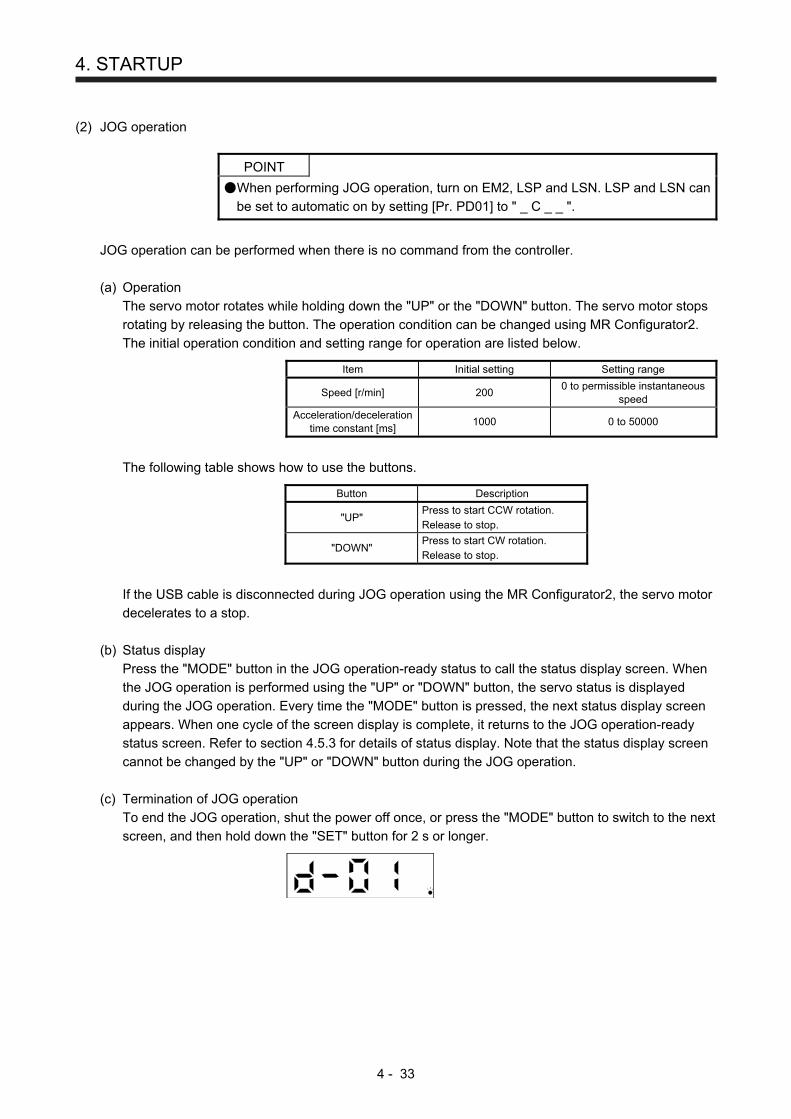
4. STARTUP
4 - 33
(2) JOG operation
POINT
When performing JOG operation, turn on EM2, LSP and LSN. LSP and LSN can
be set to automatic on by setting [Pr. PD01] to " _ C _ _ ".
JOG operation can be performed when there is no command from the controller.
(a) Operation
The servo motor rotates while holding down the "UP" or the "DOWN" button. The servo motor stops
rotating by releasing the button. The operation condition can be changed using MR Configurator2.
The initial operation condition and setting range for operation are listed below.
Item Initial setting Setting range
Speed [r/min] 200 0 to permissible instantaneous
speed
Acceleration/deceleration time constant [ms]
1000 0 to 50000
The following table shows how to use the buttons.
Button Description
"UP" Press to start CCW rotation. Release to stop.
"DOWN" Press to start CW rotation. Release to stop.
If the USB cable is disconnected during JOG operation using the MR Configurator2, the servo motor
decelerates to a stop.
(b) Status display
Press the "MODE" button in the JOG operation-ready status to call the status display screen. When
the JOG operation is performed using the "UP" or "DOWN" button, the servo status is displayed
during the JOG operation. Every time the "MODE" button is pressed, the next status display screen
appears. When one cycle of the screen display is complete, it returns to the JOG operation-ready
status screen. Refer to section 4.5.3 for details of status display. Note that the status display screen
cannot be changed by the "UP" or "DOWN" button during the JOG operation.
(c) Termination of JOG operation
To end the JOG operation, shut the power off once, or press the "MODE" button to switch to the next
screen, and then hold down the "SET" button for 2 s or longer.
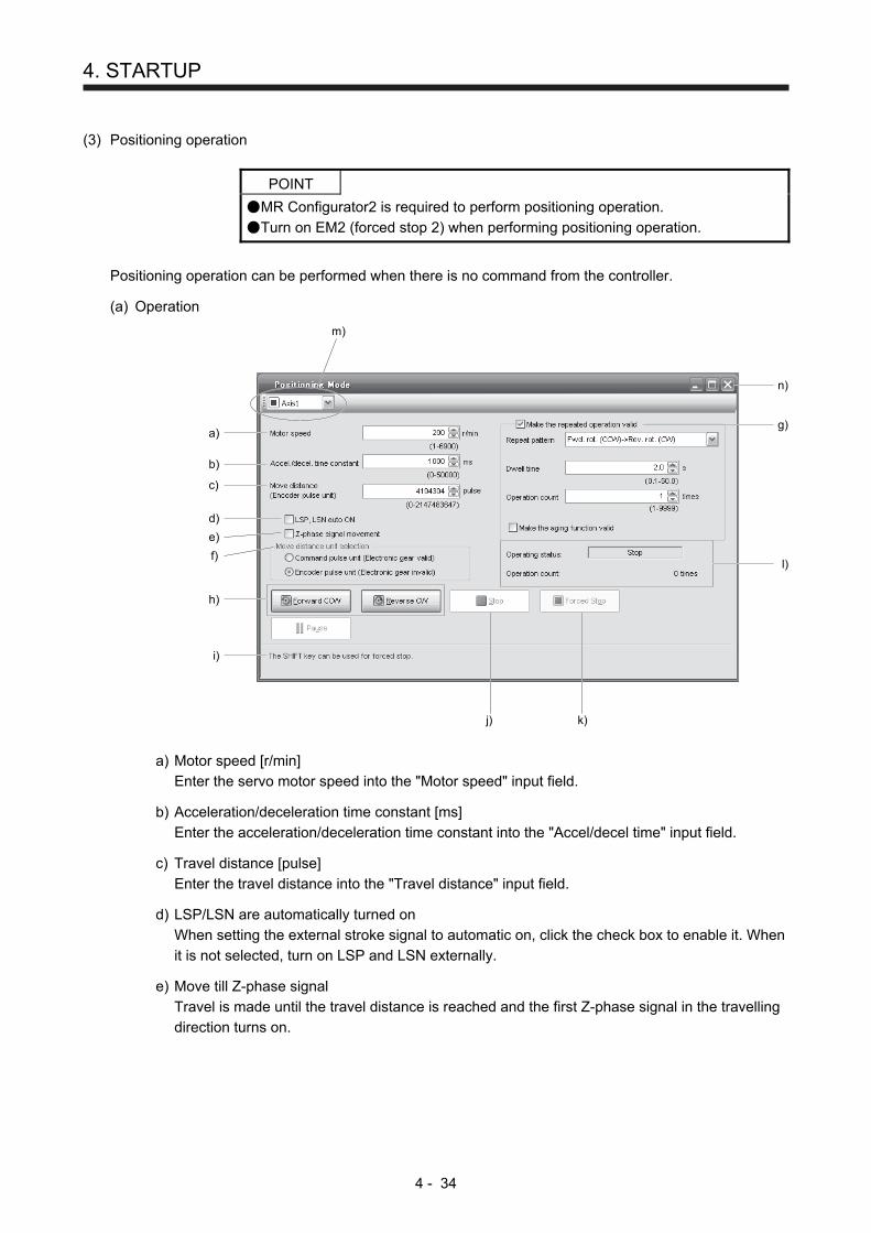
4. STARTUP
4 - 34
(3) Positioning operation
POINT
MR Configurator2 is required to perform positioning operation.
Turn on EM2 (forced stop 2) when performing positioning operation.
Positioning operation can be performed when there is no command from the controller.
(a) Operation
a)
m)
b)
n)
g)
l)
k)j)
c)
d)
e)
f)
h)
i)
a) Motor speed [r/min]
Enter the servo motor speed into the "Motor speed" input field.
b) Acceleration/deceleration time constant [ms]
Enter the acceleration/deceleration time constant into the "Accel/decel time" input field.
c) Travel distance [pulse]
Enter the travel distance into the "Travel distance" input field.
d) LSP/LSN are automatically turned on
When setting the external stroke signal to automatic on, click the check box to enable it. When
it is not selected, turn on LSP and LSN externally.
e) Move till Z-phase signal
Travel is made until the travel distance is reached and the first Z-phase signal in the travelling
direction turns on.
4. STARTUP
4 - 35
f) Travel distance unit selection
Select with the option buttons whether the travel distance set in c) is in the command pulse
unit or in the encoder pulse unit.
When the command input pulse unit is selected, the value, which is the set travel distance
multiplied by the electronic gear, will be the command value. When the encoder pulse unit is
selected, the travel distance is not multiplied by the electronic gear.
g) Enable repeat operation
To perform repeat operation, click the check. The initial setting and setting range for the repeat
operation are listed below.
Item Initial setting Setting range
Repeat pattern Fwd. rot. (CCW) to rev. rot.
(CW)
Fwd. rot. (CCW) to rev. rot. (CW)
Fwd. rot. (CCW) to fwd. rot. (CCW)
Rev. rot. (CW) to fwd. rot. (CCW)
Rev. rot. (CW) to rev. rot. (CW)
Dwell time [s] 2.0 0.1 to 50.0
Number of operations [times]
1 1 to 9999
To perform continuous operation with the repeat pattern and dwell time settings, which are set
by referring to the above table, click the check box of "Make the aging function enabled".
h) Forward/reverse the servo motor
Click the "Forward CCW" button to rotate the servo motor in the forward rotation direction.
Click the "Reverse CW" button to rotate the servo motor in the reverse rotation direction.
i) Pause the servo motor
Click the "Pause" button during servo motor rotation to temporarily stop the servo motor.
This button is enabled during servo motor rotation.
h) Stop the servo motor
Click the "Stop" button during servo motor rotation to stop the servo motor.
k) Forced stop
Click the "Forced stop" button during servo motor rotation to make a sudden stop.
This button is enabled during servo motor rotation.
l) Operation status
The operation status during the repeat operation, and the number of operations are displayed
m) Axis No.
Axis No. in operation is displayed.
n) Termination of positioning operation window
Click the close button to cancel the positioning operation mode and close the window.
(b) Status display
The status display can be checked during positioning operation.

4. STARTUP
4 - 36
(4) Motor-less operation
Without connecting the servo motor, output signals or status display can be provided in response to the
input device as if the servo motor is actually running. This operation can be used to check the sequence
of a controller or the like.
(a) Start of motor-less operation
After setting "_ _ _ 1" in [Pr. PC60], cycle the power. After that, perform external operation as in
ordinary operation.
(b) Termination of motor-less operation
To terminate the motor-less operation, set [Pr. PC60] to "_ _ _ 0" and then turn the power off.
(5) Program operation
Positioning operation can be performed in two or more operation patterns combined, without using a
controller. Use this operation with the forced stop reset. This operation may be used independently of
whether servo-on or servo-off and whether a controller is connected or not.
Exercise control on the program operation screen of MR Configurator2. For full information, refer to the
MR Configurator2 Installation Guide.
Operation Screen control
Start Click the "Operation start" button.
Stop Click the "Stop" button.
Forced stop Click the "Forced Stop" button.
(6) Output signal (DO) forced output
Output signals can be switched on/off forcibly independently of the servo status. This function is used for
output signal wiring check, etc. Exercise control on the DO forced output screen of MR Configurator2.

5. PARAMETERS
5 - 1
5. PARAMETERS
CAUTION
Never make a drastic adjustment or change to the parameter values as doing so will make the operation unstable. If fixed values are written in the digits of a parameter, do not change these values.Do not change parameters for manufacturer setting. Do not set a value other than the described values to each parameter.
5.1 Parameter list
POINT
To enable a parameter whose symbol is preceded by *, turn off the power for 1 s or more after setting and turn it on again. However, the time will be longer depending on a setting value of [Pr. PF25 instantaneous power failure tough drive - detection time] when "Instantaneous power failure tough drive selection" is enabled in [Pr. PA20]. The symbols in the control mode column mean as follows. P: Position control mode S: Speed control mode T: Torque control mode
5.1.1 Basic setting parameters ([Pr. PA_ _ ])
No. Symbol Name Initial value
Unit Control mode
P S T
PA01 *STY Operation mode 1000h
PA02 *REG Regenerative option 0000h
PA03 For manufacturer setting 0000h
PA04 *AOP1 Function selection A-1 2000h
PA05 *FBP Number of command input pulses per revolution 10000
PA06 CMX Electronic gear numerator (command pulse multiplication numerator) 1
PA07 CDV Electronic gear denominator (command pulse multiplication denominator) 1
PA08 ATU Auto tuning mode 0001h
PA09 RSP Auto tuning response 16
PA10 INP In-position range 100 [pulse]
PA11 TLP Forward rotation torque limit 100.0 [%]
PA12 TLN Reverse rotation torque limit 100.0 [%]
PA13 *PLSS Command pulse input form 0100h
PA14 *POL Rotation direction selection 0
PA15 *ENR Encoder output pulses 4000 [pulse/rev]
PA16 *ENR2 Encoder output pulses 2 1
PA17 For manufacturer setting 0000h
PA18 0000h
PA19 *BLK Parameter writing inhibit 00AAh
PA20 *TDS Tough drive setting 0000h
PA21 *AOP3 Function selection A-3 0001h
PA22 For manufacturer setting 0000h
PA23 DRAT Drive recorder arbitrary alarm trigger setting 0000h
PA24 AOP4 Function selection A-4 0000h
PA25 OTHOV One-touch tuning - Overshoot permissible level 0 [%]
PA26 *AOP5 Function selection A-5 0000h
PA27 For manufacturer setting 0000h
PA28 0000h
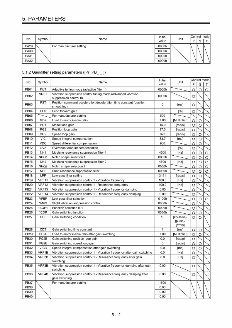
5. PARAMETERS
5 - 2
No. Symbol Name Initial value
Unit Control mode
P S T
PA29 For manufacturer setting 0000h
PA30 0000h
PA31 0000h
PA32 0000h
5.1.2 Gain/filter setting parameters ([Pr. PB_ _ ])
No. Symbol Name Initial value
Unit Control mode
P S T
PB01 FILT Adaptive tuning mode (adaptive filter II) 0000h
PB02 VRFT Vibration suppression control tuning mode (advanced vibration
suppression control II) 0000h
PB03 PST Position command acceleration/deceleration time constant (position
smoothing) 0 [ms]
PB04 FFC Feed forward gain 0 [%]
PB05 For manufacturer setting 500
PB06 GD2 Load to motor inertia ratio 7.00 [Multiplier]
PB07 PG1 Model loop gain 15.0 [rad/s]
PB08 PG2 Position loop gain 37.0 [rad/s]
PB09 VG2 Speed loop gain 823 [rad/s]
PB10 VIC Speed integral compensation 33.7 [ms]
PB11 VDC Speed differential compensation 980
PB12 OVA Overshoot amount compensation 0 [%]
PB13 NH1 Machine resonance suppression filter 1 4500 [Hz]
PB14 NHQ1 Notch shape selection 1 0000h
PB15 NH2 Machine resonance suppression filter 2 4500 [Hz]
PB16 NHQ2 Notch shape selection 2 0000h
PB17 NHF Shaft resonance suppression filter 0000h
PB18 LPF Low-pass filter setting 3141 [rad/s]
PB19 VRF11 Vibration suppression control 1 - Vibration frequency 100.0 [Hz]
PB20 VRF12 Vibration suppression control 1 - Resonance frequency 100.0 [Hz]
PB21 VRF13 Vibration suppression control 1 - Vibration frequency damping 0.00
PB22 VRF14 Vibration suppression control 1 - Resonance frequency damping 0.00
PB23 VFBF Low-pass filter selection 0100h
PB24 *MVS Slight vibration suppression control 0000h
PB25 *BOP1 Function selection B-1 0000h
PB26 *CDP Gain switching function 0000h
PB27 CDL Gain switching condition 10 [kpulse/s]/ [pulse]/ [r/min]
PB28 CDT Gain switching time constant 1 [ms]
PB29 GD2B Load to motor inertia ratio after gain switching 7.00 [Multiplier]
PB30 PG2B Gain switching position loop gain 0.0 [rad/s]
PB31 VG2B Gain switching speed loop gain 0 [rad/s]
PB32 VICB Speed integral compensation after gain switching 0.0 [ms]
PB33 VRF1B Vibration suppression control 1 - Vibration frequency after gain switching 0.0 [Hz]
PB34 VRF2B Vibration suppression control 1 - Resonance frequency after gain switching
0.0 [Hz]
PB35 VRF3B Vibration suppression control 1 - Vibration frequency damping after gain switching
0.00
PB36 VRF4B Vibration suppression control 1 - Resonance frequency damping after gain switching
0.00
PB37
For manufacturer setting 1600
PB38 0.00
PB39 0.00
PB40 0.00
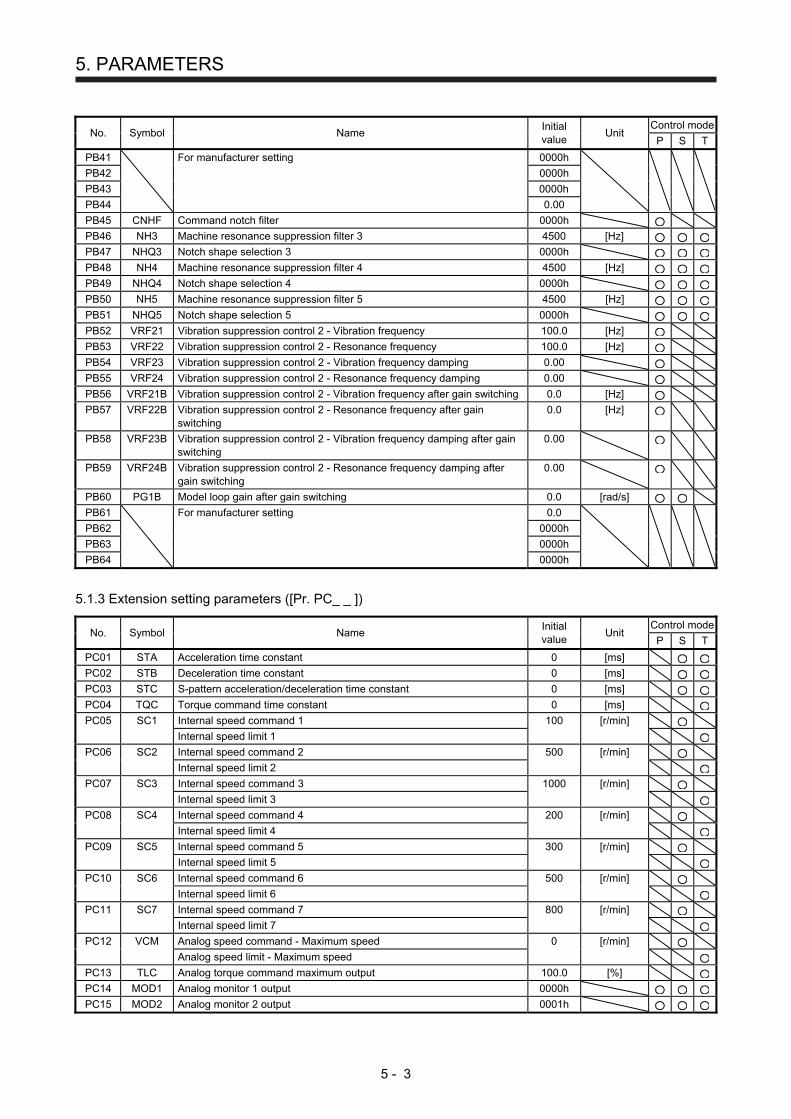
5. PARAMETERS
5 - 3
No. Symbol Name Initial value
Unit Control mode
P S T
PB41
For manufacturer setting 0000h
PB42 0000h
PB43 0000h
PB44 0.00
PB45 CNHF Command notch filter 0000h
PB46 NH3 Machine resonance suppression filter 3 4500 [Hz]
PB47 NHQ3 Notch shape selection 3 0000h
PB48 NH4 Machine resonance suppression filter 4 4500 [Hz]
PB49 NHQ4 Notch shape selection 4 0000h
PB50 NH5 Machine resonance suppression filter 5 4500 [Hz]
PB51 NHQ5 Notch shape selection 5 0000h
PB52 VRF21 Vibration suppression control 2 - Vibration frequency 100.0 [Hz]
PB53 VRF22 Vibration suppression control 2 - Resonance frequency 100.0 [Hz]
PB54 VRF23 Vibration suppression control 2 - Vibration frequency damping 0.00
PB55 VRF24 Vibration suppression control 2 - Resonance frequency damping 0.00
PB56 VRF21B Vibration suppression control 2 - Vibration frequency after gain switching 0.0 [Hz]
PB57 VRF22B Vibration suppression control 2 - Resonance frequency after gain switching
0.0 [Hz]
PB58 VRF23B Vibration suppression control 2 - Vibration frequency damping after gain switching
0.00
PB59 VRF24B Vibration suppression control 2 - Resonance frequency damping after gain switching
0.00
PB60 PG1B Model loop gain after gain switching 0.0 [rad/s]
PB61 For manufacturer setting 0.0
PB62 0000h
PB63 0000h
PB64 0000h
5.1.3 Extension setting parameters ([Pr. PC_ _ ])
No. Symbol Name Initial value
Unit Control mode
P S T
PC01 STA Acceleration time constant 0 [ms]
PC02 STB Deceleration time constant 0 [ms]
PC03 STC S-pattern acceleration/deceleration time constant 0 [ms]
PC04 TQC Torque command time constant 0 [ms]
PC05 SC1 Internal speed command 1 100 [r/min]
Internal speed limit 1
PC06 SC2 Internal speed command 2 500 [r/min]
Internal speed limit 2
PC07 SC3 Internal speed command 3 1000 [r/min]
Internal speed limit 3
PC08 SC4 Internal speed command 4 200 [r/min]
Internal speed limit 4
PC09 SC5 Internal speed command 5 300 [r/min]
Internal speed limit 5
PC10 SC6 Internal speed command 6 500 [r/min]
Internal speed limit 6
PC11 SC7 Internal speed command 7 800 [r/min]
Internal speed limit 7
PC12 VCM Analog speed command - Maximum speed 0 [r/min]
Analog speed limit - Maximum speed
PC13 TLC Analog torque command maximum output 100.0 [%]
PC14 MOD1 Analog monitor 1 output 0000h
PC15 MOD2 Analog monitor 2 output 0001h
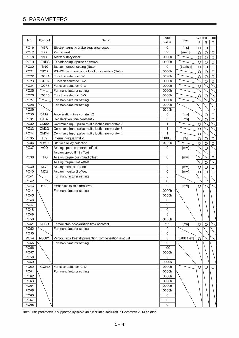
5. PARAMETERS
5 - 4
No. Symbol Name Initial value
Unit Control mode
P S T
PC16 MBR Electromagnetic brake sequence output 0 [ms]
PC17 ZSP Zero speed 50 [r/min]
PC18 *BPS Alarm history clear 0000h
PC19 *ENRS Encoder output pulse selection 0000h
PC20 *SNO Station number setting (Note) 0 [Station]
PC21 *SOP RS-422 communication function selection (Note) 0000h
PC22 *COP1 Function selection C-1 0020h
PC23 *COP2 Function selection C-2 0000h
PC24 *COP3 Function selection C-3 0000h
PC25 For manufacturer setting 0000h
PC26 *COP5 Function selection C-5 0000h
PC27 For manufacturer setting 0000h
PC28
For manufacturer setting 0000h
PC29 0000h
PC30 STA2 Acceleration time constant 2 0 [ms]
PC31 STB2 Deceleration time constant 2 0 [ms]
PC32 CMX2 Command input pulse multiplication numerator 2 1
PC33 CMX3 Command input pulse multiplication numerator 3 1
PC34 CMX4 Command input pulse multiplication numerator 4 1
PC35 TL2 Internal torque limit 2 100.0 [%]
PC36 *DMD Status display selection 0000h
PC37 VCO Analog speed command offset 0 [mV]
Analog speed limit offset
PC38 TPO Analog torque command offset 0 [mV]
Analog torque limit offset
PC39 MO1 Analog monitor 1 offset 0 [mV]
PC40 MO2 Analog monitor 2 offset 0 [mV]
PC41
For manufacturer setting 0
PC42 0
PC43 ERZ Error excessive alarm level 0 [rev]
PC44
For manufacturer setting 0000h
PC45 0000h
PC46 0
PC47 0
PC48 0
PC49 0
PC50 0000h
PC51 RSBR Forced stop deceleration time constant 100 [ms]
PC52
For manufacturer setting 0
PC53 0
PC54 RSUP1 Vertical axis freefall prevention compensation amount 0 [0.0001rev]
PC55
For manufacturer setting 0
PC56 100
PC57 0000h
PC58 0
PC59 0000h
PC60 *COPD Function selection C-D 0000h
PC61 For manufacturer setting 0000h
PC62 0000h
PC63 0000h
PC64 0000h
PC65 0000h
PC66 0
PC67 0
PC68 0 Note. This parameter is supported by servo amplifier manufactured in December 2013 or later.
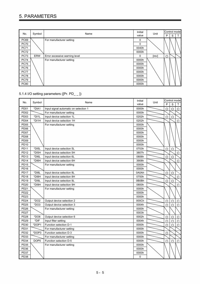
5. PARAMETERS
5 - 5
No. Symbol Name Initial value
Unit Control mode
P S T
PC69 For manufacturer setting 0
PC70 0
PC71 0040h
PC72 0000h
PC73 ERW Error excessive warning level 0 [rev]
PC74 For manufacturer setting 0000h
PC75 0000h
PC76 0000h
PC77 0000h
PC78 0000h
PC79 0000h
PC80 0000h
5.1.4 I/O setting parameters ([Pr. PD_ _ ])
No. Symbol Name Initial value
Unit Control mode
P S T
PD01 *DIA1 Input signal automatic on selection 1 0000h
PD02 For manufacturer setting 0000h
PD03 *DI1L Input device selection 1L 0202h
PD04 *DI1H Input device selection 1H 0202h
PD05
For manufacturer setting 0000h
PD06 0000h
PD07 0000h
PD08 0000h
PD09 0000h
PD10 0000h
PD11 *DI5L Input device selection 5L 0703h
PD12 *DI5H Input device selection 5H 3807h
PD13 *DI6L Input device selection 6L 0806h
PD14 *DI6H Input device selection 6H 3908h
PD15
For manufacturer setting 0000h
PD16 0000h
PD17 *DI8L Input device selection 8L 0A0Ah
PD18 *DI8H Input device selection 8H 0700h
PD19 *DI9L Input device selection 9L 0B0Bh
PD20 *DI9H Input device selection 9H 0800h
PD21
For manufacturer setting 0000h
PD22 0000h
PD23 0000h
PD24 *DO2 Output device selection 2 000Ch
PD25 *DO3 Output device selection 3 0004h
PD26
For manufacturer setting 0000h
PD27 0003h
PD28 *DO6 Output device selection 6 0002h
PD29 *DIF Input filter setting 0004h
PD30 *DOP1 Function selection D-1 0000h
PD31 For manufacturer setting 0000h
PD32 *DOP3 Function selection D-3 0000h
PD33 For manufacturer setting 0000h
PD34 DOP5 Function selection D-5 0000h
PD35
For manufacturer setting 0000h
PD36 0000h
PD37 0000h
PD38 0
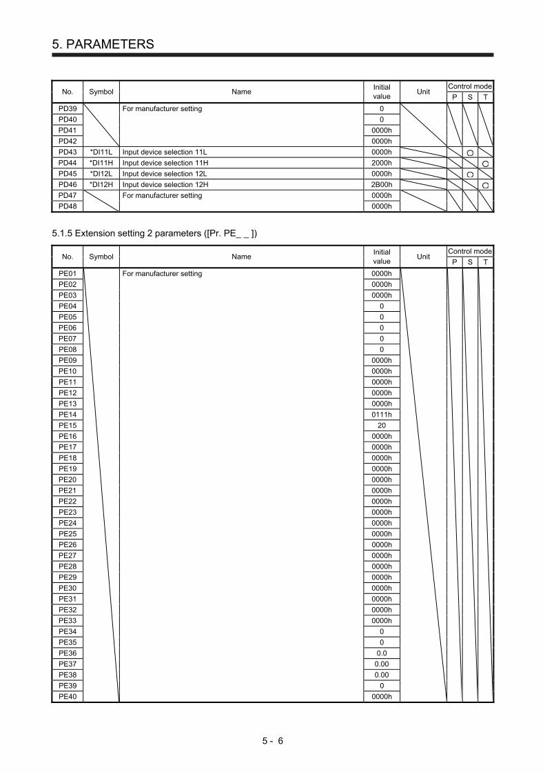
5. PARAMETERS
5 - 6
No. Symbol Name Initial value
Unit Control mode
P S T
PD39
For manufacturer setting 0
PD40 0
PD41 0000h
PD42 0000h
PD43 *DI11L Input device selection 11L 0000h
PD44 *DI11H Input device selection 11H 2000h
PD45 *DI12L Input device selection 12L 0000h
PD46 *DI12H Input device selection 12H 2B00h
PD47
For manufacturer setting 0000h
PD48 0000h
5.1.5 Extension setting 2 parameters ([Pr. PE_ _ ])
No. Symbol Name Initial value
Unit Control mode
P S T
PE01
For manufacturer setting 0000h
PE02 0000h
PE03 0000h
PE04 0
PE05 0
PE06 0
PE07 0
PE08 0
PE09 0000h
PE10 0000h
PE11 0000h
PE12 0000h
PE13 0000h
PE14 0111h
PE15 20
PE16 0000h
PE17 0000h
PE18 0000h
PE19 0000h
PE20 0000h
PE21 0000h
PE22 0000h
PE23 0000h
PE24 0000h
PE25 0000h
PE26 0000h
PE27 0000h
PE28 0000h
PE29 0000h
PE30 0000h
PE31 0000h
PE32 0000h
PE33 0000h
PE34 0
PE35 0
PE36 0.0
PE37 0.00
PE38 0.00
PE39 0
PE40 0000h
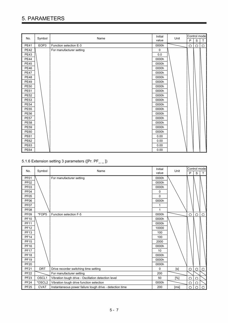
5. PARAMETERS
5 - 7
No. Symbol Name Initial value
Unit Control mode
P S T
PE41 EOP3 Function selection E-3 0000h
PE42
For manufacturer setting 0
PE43 0.0
PE44 0000h
PE45 0000h
PE46 0000h
PE47 0000h
PE48 0000h
PE49 0000h
PE50 0000h
PE51 0000h
PE52 0000h
PE53 0000h
PE54 0000h
PE55 0000h
PE56 0000h
PE57 0000h
PE58 0000h
PE59 0000h
PE60 0000h
PE61 0.00
PE62 0.00
PE63 0.00
PE64 0.00
5.1.6 Extension setting 3 parameters ([Pr. PF_ _ ])
No. Symbol Name Initial value
Unit Control mode
P S T
PF01
For manufacturer setting 0000h
PF02 0000h
PF03 0000h
PF04 0
PF05 0
PF06 0000h
PF07 1
PF08 1
PF09 *FOP5 Function selection F-5 0000h
PF10
0000h
PF11 0000h
PF12 10000
PF13 100
PF14 100
PF15 2000
PF16 0000h
PF17 10
PF18 0000h
PF19 0000h
PF20 0000h
PF21 DRT Drive recorder switching time setting 0 [s]
PF22 For manufacturer setting 200
PF23 OSCL1 Vibration tough drive - Oscillation detection level 50 [%]
PF24 *OSCL2 Vibration tough drive function selection 0000h
PF25 CVAT Instantaneous power failure tough drive - detection time 200 [ms]
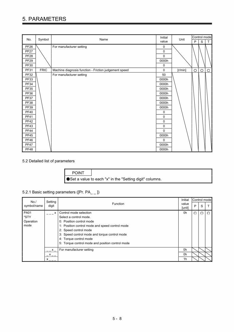
5. PARAMETERS
5 - 8
No. Symbol Name Initial value
Unit Control mode
P S T
PF26
For manufacturer setting 0
PF27 0
PF28 0
PF29 0000h
PF30 0
PF31 FRIC Machine diagnosis function - Friction judgement speed 0 [r/min]
PF32
For manufacturer setting 50
PF33 0000h
PF34 0000h
PF35 0000h
PF36 0000h
PF37 0000h
PF38 0000h
PF39 0000h
PF40 0
PF41 0
PF42 0
PF43 0
PF44 0
PF45 0000h
PF46 0
PF47 0000h
PF48 0000h
5.2 Detailed list of parameters
POINT
Set a value to each "x" in the "Setting digit" columns.
5.2.1 Basic setting parameters ([Pr. PA_ _ ])
No./ symbol/name
Setting digit
Function Initial value [unit]
Control mode
P S T
PA01 *STY Operation mode
_ _ _ x Control mode selection Select a control mode. 0: Position control mode 1: Position control mode and speed control mode 2: Speed control mode 3: Speed control mode and torque control mode 4: Torque control mode 5: Torque control mode and position control mode
0h
_ _ x _ For manufacturer setting 0h
_ x _ _ 0h
x _ _ _ 1h

5. PARAMETERS
5 - 9
No./ symbol/name
Setting digit
Function Initial value [unit]
Control mode
P S T
PA02 *REG Regenerative option
_ _ x x Regenerative option Select a regenerative option. Incorrect setting may cause the regenerative option to burn. If a selected regenerative option is not for use with the servo amplifier, [AL. 37 Parameter error] occurs. 00: Regenerative option is not used.
For servo amplifier of 200 W or less, regenerative resistor is not used. For servo amplifier of 0.4 kW to 3 kW, built-in regenerative resistor is used.
02: MR-RB032 03: MR-RB12 04: MR-RB32 05: MR-RB30 06: MR-RB50 (Cooling fan is required.)
00h
_ x _ _ For manufacturer setting 0h
x _ _ _ 0h
PA04 _ _ _ x For manufacturer setting 0h
*AOP1 _ _ x _ 0h
Function selection A-1
_ x _ _ 0h
x _ _ _ Forced stop deceleration function selection 0: Forced stop deceleration function disabled (EM1) 2: Forced stop deceleration function enabled (EM2) Refer to table 5.1 for details.
2h
Table 5.1 Deceleration method
Setting value
EM2/EM1 Deceleration method
EM2 or EM1 is off Alarm occurred
0 _ _ _ EM1 MBR (Electromagnetic brake interlock) turns off without the forced stop deceleration.
MBR (Electromagnetic brake interlock) turns off without the forced stop deceleration.
2 _ _ _ EM2 MBR (Electromagnetic brake interlock) turns off after the forced stop deceleration.
MBR (Electromagnetic brake interlock) turns off after the forced stop deceleration.
PA05 *FBP Number of command input pulses per revolution
The servo motor rotates based on set command input pulses. To enable the parameter value, select "Number of command input pulses per revolution (1 _ _ _)" of "Electronic gear selection" in [Pr. PA21]. Setting range: 1000 to 1000000
10000
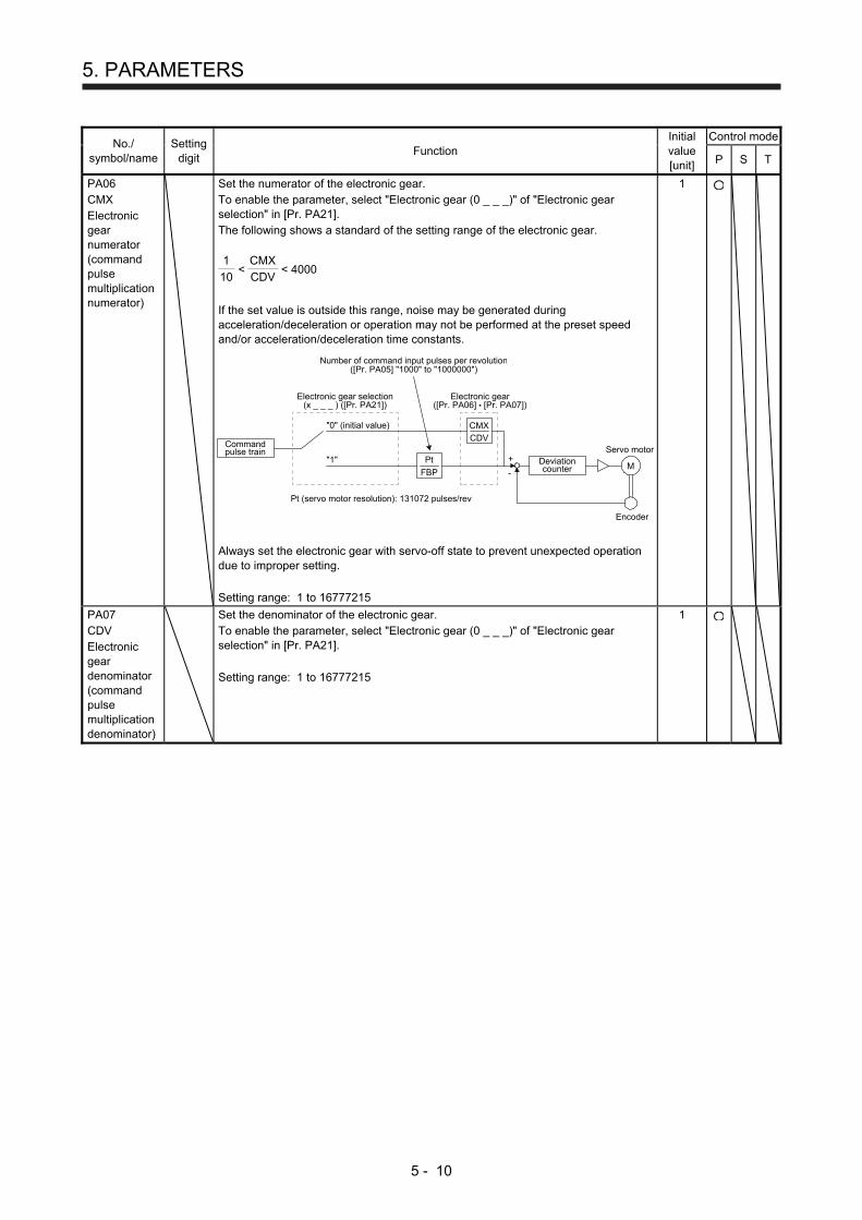
5. PARAMETERS
5 - 10
No./ symbol/name
Setting digit
Function Initial value [unit]
Control mode
P S T
PA06 CMX Electronic gear numerator (command pulse multiplication numerator)
Set the numerator of the electronic gear. To enable the parameter, select "Electronic gear (0 _ _ _)" of "Electronic gear selection" in [Pr. PA21]. The following shows a standard of the setting range of the electronic gear. 1
10 <
CMX
CDV < 4000
If the set value is outside this range, noise may be generated during acceleration/deceleration or operation may not be performed at the preset speed and/or acceleration/deceleration time constants.
CDV
FBP
Commandpulse train
Pt
"0" (initial value) CMX
Deviationcounter
+
-
Electronic gear([Pr. PA06] [Pr. PA07])
Number of command input pulses per revolution([Pr. PA05] "1000" to "1000000")
Servo motor
Encoder
M"1"
Electronic gear selection(x _ _ _ ) ([Pr. PA21])
Pt (servo motor resolution): 131072 pulses/rev
Always set the electronic gear with servo-off state to prevent unexpected operation due to improper setting. Setting range: 1 to 16777215
1
PA07 CDV Electronic gear denominator (command pulse multiplication denominator)
Set the denominator of the electronic gear. To enable the parameter, select "Electronic gear (0 _ _ _)" of "Electronic gear selection" in [Pr. PA21]. Setting range: 1 to 16777215
1

5. PARAMETERS
5 - 11
No./ symbol/name
Setting digit
Function Initial value [unit]
Control mode
P S T
PA08 ATU Auto tuning mode
_ _ _ x Gain adjustment mode selection Select the gain adjustment mode. 0: 2 gain adjustment mode 1 (interpolation mode) 1: Auto tuning mode 1 2: Auto tuning mode 2 3: Manual mode 4: 2 gain adjustment mode 2 Refer to table 5.2 for details.
1h
_ _ x _ For manufacturer setting 0h
_ x _ _ 0h
x _ _ _ 0h
Table 5.2 Gain adjustment mode selection
Setting value
Gain adjustment mode
Automatically adjusted parameter
_ _ _ 0 2 gain adjustment mode 1 (interpolation mode)
[Pr. PB06 Load to motor inertia ratio] [Pr. PB08 Position loop gain] [Pr. PB09 Speed loop gain] [Pr. PB10 Speed integral compensation]
_ _ _ 1 Auto tuning mode 1 [Pr. PB06 Load to motor inertia ratio] [Pr. PB07 Model loop gain] [Pr. PB08 Position loop gain] [Pr. PB09 Speed loop gain] [Pr. PB10 Speed integral compensation]
_ _ _ 2 Auto tuning mode 2 [Pr. PB07 Model loop gain] [Pr. PB08 Position loop gain] [Pr. PB09 Speed loop gain] [Pr. PB10 Speed integral compensation]
_ _ _ 3 Manual mode
_ _ _ 4 2 gain adjustment mode 2
[Pr. PB08 Position loop gain] [Pr. PB09 Speed loop gain] [Pr. PB10 Speed integral compensation]

5. PARAMETERS
5 - 12
No./ symbol/name
Setting digit
Function Initial value [unit]
Control mode
P S T
PA09 RSP Auto tuning response
Set a response of the auto tuning.
16
Setting value
Machine characteristic
Setting value
Machine characteristic
Response
Guideline for machine
resonance frequency [Hz]
Response
Guideline for machine
resonance frequency [Hz]
1 Low
response
2.7 21
Middle respon
se
67.1
2
3.6 22
75.6
3 4.9 23 85.2
4 6.6 24 95.9
5 10.0 25 108.0
6 11.3 26 121.7
7 12.7 27 137.1
8 14.3 28 154.4
9 16.1 29 173.9
10 18.1 30 195.9
11 20.4 31 220.6
12 23.0 32 248.5
13 25.9 33 279.9
14 29.2 34 315.3
15 32.9 35 355.1
16 37.0 36 400.0
17 41.7 37 446.6
18 47.0 38 501.2
19 52.9 39 571.5
20 Middle respon
se
59.6 40
High respon
se
642.7
Setting range: 1 to 40
PA10 INP In-position range
Set an in-position range per command pulse. To change it to the servo motor encoder pulse unit, set [Pr. PC24]. Setting range: 0 to 65535
100 [pulse]
PA11 TLP Forward rotation torque limit
You can limit the torque generated by the servo motor. Set the parameter referring section 3.6.1 (5). The larger value of [Pr. PA11 Forward rotation torque limit] or [Pr. PA12 Reverse rotation torque limit] will be the maximum output voltage (8 V). Set the parameter on the assumption that the maximum torque is 100 [%]. The parameter is for limiting the torque of the servo motor in the CCW power running or CW regeneration. Set this parameter to "0.0" to generate no torque. Setting range: 0.0 to 100.0
100.0 [%]
PA12 TLN Reverse rotation torque limit
You can limit the torque generated by the servo motor. Set the parameter referring section 3.6.1 (5). The larger value of [Pr. PA11 Forward rotation torque limit] or [Pr. PA12 Reverse rotation torque limit] will be the maximum output voltage (8 V). Set the parameter on the assumption that the maximum torque is 100 [%]. The parameter is for limiting the torque of the servo motor in the CW power running or CCW regeneration. Set this parameter to "0.0" to generate no torque. Setting range: 0.0 to 100.0
100.0 [%]
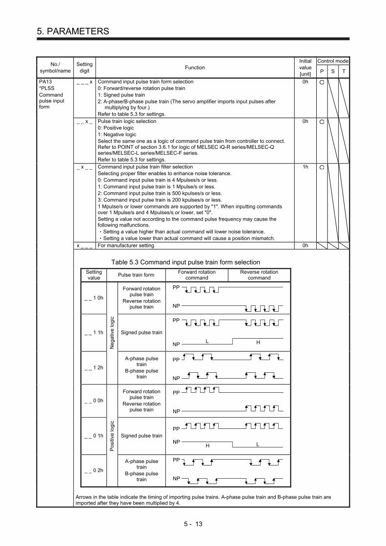
5. PARAMETERS
5 - 13
No./ symbol/name
Setting digit
Function Initial value [unit]
Control mode
P S T
PA13 *PLSS Command pulse input form
_ _ _ x Command input pulse train form selection 0: Forward/reverse rotation pulse train 1: Signed pulse train 2: A-phase/B-phase pulse train (The servo amplifier imports input pulses after
multiplying by four.) Refer to table 5.3 for settings.
0h
_ _ x _ Pulse train logic selection 0: Positive logic 1: Negative logic Select the same one as a logic of command pulse train from controller to connect. Refer to POINT of section 3.6.1 for logic of MELSEC iQ-R series/MELSEC-Q series/MELSEC-L series/MELSEC-F series. Refer to table 5.3 for settings.
0h
_ x _ _ Command input pulse train filter selection Selecting proper filter enables to enhance noise tolerance. 0: Command input pulse train is 4 Mpulses/s or less. 1: Command input pulse train is 1 Mpulse/s or less. 2: Command input pulse train is 500 kpulses/s or less. 3: Command input pulse train is 200 kpulses/s or less. 1 Mpulse/s or lower commands are supported by "1". When inputting commands over 1 Mpulse/s and 4 Mpulses/s or lower, set "0". Setting a value not according to the command pulse frequency may cause the following malfunctions.
Setting a value higher than actual command will lower noise tolerance. Setting a value lower than actual command will cause a position mismatch.
1h
x _ _ _ For manufacturer setting 0h
Table 5.3 Command input pulse train form selection
Setting value
Pulse train form Forward rotation
command Reverse rotation
command
_ _ 1 0h
Forward rotation pulse train
Reverse rotation pulse train NP
PP
_ _ 1 1h
Neg
ativ
e lo
gic
Signed pulse train
PP
L HNP
_ _ 1 2h
A-phase pulse train
B-phase pulse train
PP
NP
_ _ 0 0h
Forward rotation pulse train
Reverse rotation pulse train NP
PP
_ _ 0 1h
Po
sitiv
e lo
gic
Signed pulse train
LH
PP
NP
_ _ 0 2h
A-phase pulse train
B-phase pulse train
PP
NP
Arrows in the table indicate the timing of importing pulse trains. A-phase pulse train and B-phase pulse train are
imported after they have been multiplied by 4.
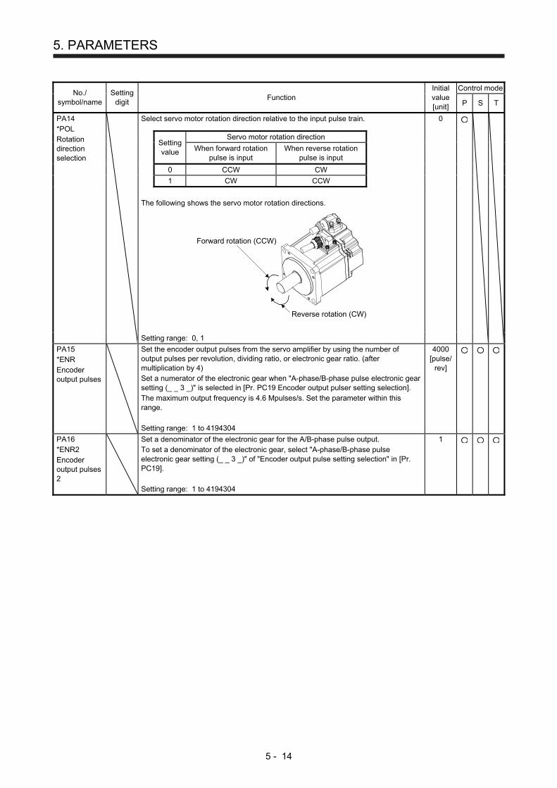
5. PARAMETERS
5 - 14
No./ symbol/name
Setting digit
Function Initial value [unit]
Control mode
P S T
PA14 *POL Rotation direction selection
Select servo motor rotation direction relative to the input pulse train.
0
Setting value
Servo motor rotation direction
When forward rotation
pulse is input When reverse rotation
pulse is input
0 CCW CW
1 CW CCW
The following shows the servo motor rotation directions.
Forward rotation (CCW)
Reverse rotation (CW)
Setting range: 0, 1
PA15 *ENR Encoder output pulses
Set the encoder output pulses from the servo amplifier by using the number of output pulses per revolution, dividing ratio, or electronic gear ratio. (after multiplication by 4) Set a numerator of the electronic gear when "A-phase/B-phase pulse electronic gear setting (_ _ 3 _)" is selected in [Pr. PC19 Encoder output pulser setting selection]. The maximum output frequency is 4.6 Mpulses/s. Set the parameter within this range. Setting range: 1 to 4194304
4000 [pulse/
rev]
PA16 *ENR2 Encoder output pulses 2
Set a denominator of the electronic gear for the A/B-phase pulse output. To set a denominator of the electronic gear, select "A-phase/B-phase pulse electronic gear setting (_ _ 3 _)" of "Encoder output pulse setting selection" in [Pr. PC19]. Setting range: 1 to 4194304
1

5. PARAMETERS
5 - 15
No./ symbol/name
Setting digit
Function Initial value [unit]
Control mode
P S T
PA19 *BLK Parameter writing inhibit
Select a reference range and writing range of the parameter. Refer to table 5.4 for settings.
00AAh
Table 5.4 [Pr. PA19] setting value and reading/writing range
PA19
Setting operation
PA PB PC PD PE PF
Other than
below
Reading
Writing
000Ah
Reading Only 19
Writing Only 19
000Bh
Reading
Writing
000Ch
Reading
Writing
00AAh (initial value)
Reading
Writing
100Bh
Reading
Writing Only 19
100Ch
Reading
Writing Only 19
10AAh
Reading
Writing Only 19
PA20 *TDS Tough drive setting
Alarms may not be avoided with the tough drive function depending on the situations of the power supply and load fluctuation. You can assign MTTR (During tough drive) to pins CN1-23, CN1-24, and CN1-49 with [Pr. PD24], [Pr. PD25], and [Pr. PD28].
_ _ _ x For manufacturer setting 0h
_ _ x _ Vibration tough drive selection 0: Disabled 1: Enabled Selecting "1" enables to suppress vibrations by automatically changing setting values of [Pr. PB13 Machine resonance suppression filter 1] and [Pr. PB15 Machine resonance suppression filter 2] in case that the vibration exceed the value of the oscillation level set in [Pr. PF23]. To output the oscillation detection alarm as a warning, set [Pr. PF24 Vibration tough drive function selection]. Refer to section 7.3 for details.
0h
_ x _ _ Instantaneous power failure tough drive selection 0: Disabled 1: Enabled Selecting "1" enables to avoid occurring [AL. 10 Undervoltage] using the electrical energy charged in the capacitor in the servo amplifier in case that an instantaneous power failure occurs during operation. In [Pr. PF25 Instantaneous power failure tough drive - Detection time], set the time until the occurrence of [AL. 10.1 Voltage drop in the power]. When the parameter is enabled, the power should be off for the setting value of [Pr. PF25] + 1 s or more before cycling the power to enable a parameter whose symbol is preceded by "*".
0h
x _ _ _ For manufacturer setting 0h

5. PARAMETERS
5 - 16
No./ symbol/name
Setting digit
Function Initial value [unit]
Control mode
P S T
PA21 *AOP3 Function selection A-3
_ _ _ x One-touch tuning function selection 0: Disabled 1: Enabled When the digit is "0", the one-touch tuning is not available.
1h
_ _ x _ For manufacturer setting 0h
_ x _ _ 0h
x _ _ _ Electronic gear selection 0: Electronic gear ([Pr. PA06] and [Pr. PA07]) 1: Number of command input pulses per revolution ([Pr. PA05])
0h
PA23 DRAT Drive recorder arbitrary alarm trigger setting
_ _ x x Alarm detail No. setting Set the digits when you execute the trigger with arbitrary alarm detail No. for the drive recorder function. When these digits are "0 0", only the arbitrary alarm No. setting will be enabled.
00h
x x _ _ Alarm No. setting Set the digits when you execute the trigger with arbitrary alarm No. for the drive recorder function. When "0 0" are set, arbitrary alarm trigger of the drive recorder will be disabled.
00h
Setting example: To activate the drive recorder when [AL. 50 Overload 1] occurs, set "5 0 0 0". To activate the drive recorder when [AL. 50.3 Thermal overload error 4 during operation] occurs, set "5 0 0 3".
PA24 AOP4 Function selection A-4
_ _ _ x Vibration suppression mode selection 0: Standard mode 1: 3 inertia mode 2: Low response mode When you select the standard mode or low response mode, "Vibration suppression control 2" is not available. When you select the 3 inertia mode, the feed forward gain is not available. Before changing the control mode during the 3 inertia mode or low response mode, stop the motor.
0h
_ _ x _ For manufacturer setting 0h
_ x _ _ 0h
x _ _ _ 0h
PA25 OTHOV One-touch tuning - Overshoot permissible level
Set a permissible value of overshoot amount for one-touch tuning as a percentage of the in-position range. However, setting "0" will be 50%.
0 [%]
PA26 *AOP5 Function selection A-5
_ _ _ x Torque limit function selection at instantaneous power failure 0: Disabled 1: Enabled Selecting "1" for this digit will limit torques to save electric energy when an instantaneous power failure occurs during operation and will make [AL. 10 Undervoltage] less likely to occur. The torque limit function at instantaneous power failure is enabled when "Instantaneous power failure tough drive selection" in [Pr. PA20] is "Enabled (_ 1 _ _)".
0h
_ _ x _ For manufacturer setting 0h
_ x _ _ 0h
x _ _ _ 0h

5. PARAMETERS
5 - 17
5.2.2 Gain/filter setting parameters ([Pr. PB_ _ ])
No./ symbol/name
Setting digit
Function Initial value [unit]
Control mode
P S T
PB01 FILT Adaptive tuning mode (adaptive filter II)
_ _ _ x Filter tuning mode selection Set the adaptive filter tuning. Select the adjustment mode of the machine resonance suppression filter 1. Refer to section 7.1.2 for details. 0: Disabled 1: Automatic setting (Do not use this in the torque control mode.) 2: Manual setting
0h
_ _ x _ For manufacturer setting 0h
_ x _ _ 0h
x _ _ _ 0h
PB02 VRFT Vibration suppression control tuning mode (advanced vibration suppression control II)
_ _ _ x Vibration suppression control 1 tuning mode selection Select the tuning mode of the vibration suppression control 1. Refer to section 7.1.5 for details. 0: Disabled 1: Automatic setting 2: Manual setting
0h
_ _ x _ Vibration suppression control 2 tuning mode selection Select the tuning mode of the vibration suppression control 2. To enable the digit, select "3 inertia mode (_ _ _ 1)" of "Vibration suppression mode selection" in [Pr. PA24]. Refer to section 7.1.5 for details. 0: Disabled 1: Automatic setting 2: Manual setting
0h
_ x _ _ For manufacturer setting 0h
x _ _ _ 0h
PB03 PST Position command acceleration/ deceleration time constant (position smoothing)
Set the constant of a primary delay to the position command. You can select a control method from "Primary delay" or "Linear acceleration/deceleration" in [Pr. PB25 Function selection B-1]. The setting range of "Linear acceleration/deceleration" is 0 ms to 10 ms. Setting of longer than 10 ms will be recognized as 10 ms. When the linear acceleration/deceleration is selected, do not set the "Control mode selection" ([Pr. PA01]) to the setting other than "_ _ _ 0". Doing so will cause the servo motor to make a sudden stop at the time of position control mode switching. (Example) When a command is given from a synchronizing encoder, synchronous
operation will start smoothly even if it start during line operation.
Synchronizingencoder
Start Servo motorServo amplifier
ONOFF
With timeconstant setting
Without timeconstant setting
Servo motorspeed
Start
t
Setting range: 0 to 65535
0 [ms]
5. PARAMETERS
5 - 18
No./ symbol/name
Setting digit
Function Initial value [unit]
Control mode
P S T
PB04 FFC Feed forward gain
Set the feed forward gain. When the setting is 100%, the droop pulses during operation at constant speed are nearly zero. However, sudden acceleration/deceleration will increase the overshoot. As a guideline, when the feed forward gain setting is 100%, set 1 s or more as the acceleration time constant up to the rated speed. Setting range: 0 to 100
0 [%]
PB06 GD2 Load to motor inertia ratio
Set the load to motor inertia ratio. The setting of the parameter will be the automatic setting or manual setting depending on the [Pr. PA08] setting. Refer to the following table for details. When the parameter is automatic setting, the value will vary between 0.00 and 100.00. Setting range: 0.00 to 300.00
7.00 [Multiplier]
Pr. PA08 This parameter
_ _ _ 0 (2 gain adjustment mode 1 (interpolation mode)
Automatic setting
_ _ _ 1: (Auto tuning mode 1)
_ _ _ 2: (Auto tuning mode 2) Manual setting
_ _ _ 3: (Manual mode)
_ _ _ 4: (2 gain adjustment mode 2)
PB07 PG1 Model loop gain
Set the response gain up to the target position. Increasing the setting value will also increase the response level to the position command but will be liable to generate vibration and/or noise. The setting of the parameter will be the automatic setting or manual setting depending on the [Pr. PA08] setting. Refer to the following table for details. Setting range: 1.0 to 2000.0
15.0 [rad/s]
Pr. PA08 This parameter
_ _ _ 0 (2 gain adjustment mode 1 (interpolation mode)
Manual setting
_ _ _ 1: (Auto tuning mode 1) Automatic setting
_ _ _ 2: (Auto tuning mode 2)
_ _ _ 3: (Manual mode) Manual setting
_ _ _ 4: (2 gain adjustment mode 2)
PB08 PG2 Position loop gain
Set the gain of the position loop. Set this parameter to increase the position response to level load disturbance. Increasing the setting value will also increase the response level to the load disturbance but will be liable to generate vibration and/or noise. The setting of the parameter will be the automatic setting or manual setting depending on the [Pr. PA08] setting. Refer to the following table for details. Setting range: 1.0 to 2000.0
37.0 [rad/s]
Pr. PA08 This parameter
_ _ _ 0 (2 gain adjustment mode 1 (interpolation mode)
Automatic setting
_ _ _ 1: (Auto tuning mode 1)
_ _ _ 2: (Auto tuning mode 2)
_ _ _ 3: (Manual mode) Manual setting
_ _ _ 4: (2 gain adjustment mode 2) Automatic setting
5. PARAMETERS
5 - 19
No./ symbol/name
Setting digit
Function Initial value [unit]
Control mode
P S T
PB09 VG2 Speed loop gain
Set the gain of the speed loop. Set this parameter when vibration occurs on machines of low rigidity or large backlash. Increasing the setting value will also increase the response level but will be liable to generate vibration and/or noise. The setting of the parameter will be the automatic setting or manual setting depending on the [Pr. PA08] setting. Refer to the table of [Pr. PB08] for details. Setting range: 20 to 65535
823 [rad/s]
PB10 VIC Speed integral compensation
Set the integral time constant of the speed loop. Decreasing the setting value will increase the response level but will be liable to generate vibration and/or noise. The setting of the parameter will be the automatic setting or manual setting depending on the [Pr. PA08] setting. Refer to the table of [Pr. PB08] for details. Setting range: 0.1 to 1000.0
33.7 [ms]
PB11 VDC Speed differential compensation
Set the differential compensation. To enable the setting value, turn on PC (proportional control). Setting range: 0 to 1000
980
PB12 OVA Overshoot amount compensation
Set a viscous friction torque per percent to the servo motor rated speed. When the response level is low, or when the torque is limited, the efficiency of the parameter can be lower. Setting range: 0 to 100
0 [%]
PB13 NH1 Machine resonance suppression filter 1
Machine resonance suppression filter 1 Set the notch frequency of the machine resonance suppression filter 1. When "Automatic setting (_ _ _ 1)" of "Filter tuning mode selection" is selected in [Pr. PB01], this parameter will be adjusted automatically. When you select "Manual setting (_ _ _ 2)" of "Filter tuning mode selection" in [Pr. PB01], the setting value will be enabled. Setting range: 10 to 4500
4500 [Hz]
PB14 NHQ1 Notch shape selection 1
Set the shape of the machine resonance suppression filter 1. When you select "Automatic setting (_ _ _ 1)" of "Filter tuning mode selection" in [Pr. PB01], this parameter will be adjusted automatically. Set manually for the manual setting.
_ _ _ x For manufacturer setting 0h
_ _ x _ Notch depth selection 0: -40 dB 1: -14 dB 2: -8 dB 3: -4 dB
0h
_ x _ _ Notch width selection 0: α = 2 1: α = 3 2: α = 4 3: α = 5
0h
x _ _ _ For manufacturer setting 0h
PB15 NH2 Machine resonance suppression filter 2
Set the notch frequency of the machine resonance suppression filter 2. To enable the setting value, select "Enabled (_ _ _ 1)" of "Machine resonance suppression filter 2 selection" in [Pr. PB16]. Setting range: 10 to 4500
4500 [Hz]

5. PARAMETERS
5 - 20
No./ symbol/name
Setting digit
Function Initial value [unit]
Control mode
P S T
PB16 NHQ2 Notch shape selection 2
Set the shape of the machine resonance suppression filter 2.
_ _ _ x Machine resonance suppression filter 2 selection 0: Disabled 1: Enabled
0h
_ _ x _ Notch depth selection 0: -40 dB 1: -14 dB 2: -8 dB 3: -4 dB
0h
_ x _ _ Notch width selection 0: α = 2 1: α = 3 2: α = 4 3: α = 5
0h
x _ _ _ For manufacturer setting 0h
PB17 NHF Shaft resonance suppression filter
Set the shaft resonance suppression filter. Use this filter to suppress a low-frequency machine vibration. When you select "Automatic setting (_ _ _ 0)" of "Shaft resonance suppression filter selection" in [Pr. PB23], the value will be calculated automatically from the servo motor you use and load to motor inertia ratio. Set manually for "Manual setting (_ _ _ 1)". When "Shaft resonance suppression filter selection" is "Disabled (_ _ _ 2)" in [Pr. PB23], the setting value of this parameter will be disabled. When you select "Enabled (_ _ _ 1)" of "Machine resonance suppression filter 4 selection" in [Pr. PB49], the shaft resonance suppression filter is not available.
_ _ x x Shaft resonance suppression filter setting frequency selection Refer to table 5.5 for settings. Set the value closest to the frequency you need.
00h
_ x _ _ Notch depth selection 0: -40 dB 1: -14 dB 2: -8 dB 3: -4 dB
0h
x _ _ _ For manufacturer setting 0h
Table 5.5 Shaft resonance suppression filter
setting frequency selection
Setting value
Frequency [Hz] Setting
value Frequency [Hz]
00 Disabled 10 562
01 Disabled 11 529
02 4500 12 500
03 3000 13 473
04 2250 14 450
05 1800 15 428
06 1500 16 409
07 1285 17 391
08 1125 18 375
09 1000 19 360
0A 900 1A 346
0B 818 1B 333
0C 750 1C 321
0D 692 1D 310
0E 642 1E 300
0F 600 1F 290

5. PARAMETERS
5 - 21
No./ symbol/name
Setting digit
Function Initial value [unit]
Control mode
P S T
PB18 LPF Low-pass filter setting
Set the low-pass filter. The following shows a relation of a required parameter to this parameter. Setting range: 100 to 18000
3141 [rad/s]
[Pr. PB23] [Pr. PB18]
_ _ 0 _ (Initial value) Automatic setting
_ _ 1 _ Setting value enabled
_ _ 2 _ Setting value disabled
PB19 VRF11 Vibration suppression control 1 - Vibration frequency
Set the vibration frequency for vibration suppression control 1 to suppress low-frequency machine vibration. When "Vibration suppression control 1 tuning mode selection" is "Automatic setting (_ _ _ 1)" in [Pr. PB02], this parameter will be set automatically. Set manually for "Manual setting (_ _ _ 2)". Refer to section 7.1.5 for details. Setting range: 0.1 to 300.0
100.0 [Hz]
PB20 VRF12 Vibration suppression control 1 - Resonance frequency
Set the resonance frequency for vibration suppression control 1 to suppress low-frequency machine vibration. When "Vibration suppression control 1 tuning mode selection" is "Automatic setting (_ _ _ 1)" in [Pr. PB02], this parameter will be set automatically. Set manually for "Manual setting (_ _ _ 2)". Refer to section 7.1.5 for details. Setting range: 0.1 to 300.0
100.0 [Hz]
PB21 VRF13 Vibration suppression control 1 - Vibration frequency damping
Set a damping of the vibration frequency for vibration suppression control 1 to suppress low-frequency machine vibration. When "Vibration suppression control 1 tuning mode selection" is "Automatic setting (_ _ _ 1)" in [Pr. PB02], this parameter will be set automatically. Set manually for "Manual setting (_ _ _ 2)". Refer to section 7.1.5 for details. Setting range: 0.00 to 0.30
0.00
PB22 VRF14 Vibration suppression control 1 - Resonance frequency damping
Set a damping of the resonance frequency for vibration suppression control 1 to suppress low-frequency machine vibration. When "Vibration suppression control 1 tuning mode selection" is "Automatic setting (_ _ _ 1)" in [Pr. PB02], this parameter will be set automatically. Set manually for "Manual setting (_ _ _ 2)". Refer to section 7.1.5 for details. Setting range: 0.00 to 0.30
0.00
PB23 VFBF Low-pass filter selection
_ _ _ x Shaft resonance suppression filter selection Select the shaft resonance suppression filter. 0: Automatic setting 1: Manual setting 2: Disabled When you select "Enabled (_ _ _ 1)" of "Machine resonance suppression filter 4 selection" in [Pr. PB49], the shaft resonance suppression filter is not available.
0h
_ _ x _ Low-pass filter selection Select the low-pass filter. 0: Automatic setting 1: Manual setting 2: Disabled
0h
_ x _ _ For manufacturer setting 1h
x _ _ _ 0h
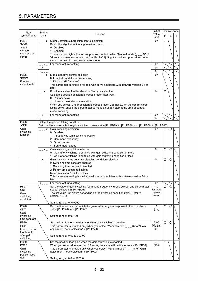
5. PARAMETERS
5 - 22
No./ symbol/name
Setting digit
Function Initial value [unit]
Control mode
P S T
PB24 *MVS Slight vibration suppression control
_ _ _ x Slight vibration suppression control selection Select the slight vibration suppression control. 0: Disabled 1: Enabled To enable the slight vibration suppression control, select "Manual mode (_ _ _ 3)" of "Gain adjustment mode selection" in [Pr. PA08]. Slight vibration suppression control cannot be used in the speed control mode.
0h
_ _ x _ For manufacturer setting 0h _ x _ _ 0h x _ _ _ 0h PB25 *BOP1 Function selection B-1
_ _ _ x Model adaptive control selection 0: Enabled (model adaptive control) 2: Disabled (PID control) This parameter setting is available with servo amplifiers with software version B4 or later.
0h
_ _ x _ Position acceleration/deceleration filter type selection Select the position acceleration/deceleration filter type. 0: Primary delay 1: Linear acceleration/deceleration When you select "Linear acceleration/deceleration", do not switch the control mode. Doing so will cause the servo motor to make a sudden stop at the time of control mode switching.
0h
_ x _ _ For manufacturer setting 0h x _ _ _ 0h PB26 *CDP Gain switching function
Select the gain switching condition. Set conditions to enable the gain switching values set in [Pr. PB29] to [Pr. PB36] and [Pr. PB56] to [Pr. PB60]. _ _ _ x Gain switching selection
0: Disabled 1: Input device (gain switching (CDP)) 2: Command frequency 3: Droop pulses 4: Servo motor speed
0h
_ _ x _ Gain switching condition selection 0: Gain after switching is enabled with gain switching condition or more 1: Gain after switching is enabled with gain switching condition or less
0h
_ x _ _ Gain switching time constant disabling condition selection 0: Switching time constant enabled 1: Switching time constant disabled 2: Return time constant disabled Refer to section 7.2.4 for details. This parameter setting is available with servo amplifiers with software version B4 or later.
0h
x _ _ _ For manufacturing setting 0h PB27 CDL Gain switching condition
Set the value of gain switching (command frequency, droop pulses, and servo motor speed) selected in [Pr. PB26]. The set value unit differs depending on the switching condition item. (Refer to section 7.2.3.) Setting range: 0 to 9999
10 [kpulse/s] /[pulse] /[r/min]
PB28 CDT Gain switching time constant
Set the time constant at which the gains will change in response to the conditions set in [Pr. PB26] and [Pr. PB27]. Setting range: 0 to 100
1 [ms]
PB29 GD2B Load to motor inertia ratio after gain switching
Set the load to motor inertia ratio when gain switching is enabled. This parameter is enabled only when you select "Manual mode (_ _ _ 3)" of "Gain adjustment mode selection" in [Pr. PA08]. Setting range: 0.00 to 300.00
7.00 [Multipli
er]
PB30 PG2B Gain switching position loop gain
Set the position loop gain when the gain switching is enabled. When you set a value less than 1.0 rad/s, the value will be the same as [Pr. PB08]. This parameter is enabled only when you select "Manual mode (_ _ _ 3)" of "Gain adjustment mode selection" in [Pr. PA08]. Setting range: 0.0 to 2000.0
0.0 [rad/s]
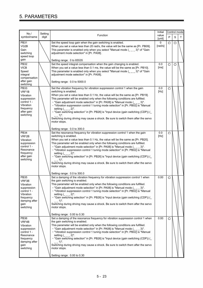
5. PARAMETERS
5 - 23
No./ symbol/name
Setting digit
Function Initial value [unit]
Control mode
P S T
PB31 VG2B Gain switching speed loop gain
Set the speed loop gain when the gain switching is enabled. When you set a value less than 20 rad/s, the value will be the same as [Pr. PB09]. This parameter is enabled only when you select "Manual mode (_ _ _ 3)" of "Gain adjustment mode selection" in [Pr. PA08]. Setting range: 0 to 65535
0 [rad/s]
PB32 VICB Speed integral compensation after gain switching
Set the speed integral compensation when the gain changing is enabled. When you set a value less than 0.1 ms, the value will be the same as [Pr. PB10]. This parameter is enabled only when you select "Manual mode (_ _ _ 3)" of "Gain adjustment mode selection" in [Pr. PA08]. Setting range: 0.0 to 5000.0
0.0 [ms]
PB33 VRF1B Vibration suppression control 1 - Vibration frequency after gain switching
Set the vibration frequency for vibration suppression control 1 when the gain switching is enabled. When you set a value less than 0.1 Hz, the value will be the same as [Pr. PB19]. This parameter will be enabled only when the following conditions are fulfilled.
"Gain adjustment mode selection" in [Pr. PA08] is "Manual mode (_ _ _ 3)". "Vibration suppression control 1 tuning mode selection" in [Pr. PB02] is "Manual setting (_ _ _ 2)". "Gain switching selection" in [Pr. PB26] is "Input device (gain switching (CDP)) (_ _ _ 1)".
Switching during driving may cause a shock. Be sure to switch them after the servo motor stops. Setting range: 0.0 to 300.0
0.0 [Hz]
PB34 VRF2B Vibration suppression control 1 - Resonance frequency after gain switching
Set the resonance frequency for vibration suppression control 1 when the gain switching is enabled. When you set a value less than 0.1 Hz, the value will be the same as [Pr. PB20]. This parameter will be enabled only when the following conditions are fulfilled.
"Gain adjustment mode selection" in [Pr. PA08] is "Manual mode (_ _ _ 3)". "Vibration suppression control 1 tuning mode selection" in [Pr. PB02] is "Manual setting (_ _ _ 2)". "Gain switching selection" in [Pr. PB26] is "Input device (gain switching (CDP)) (_ _ _ 1)".
Switching during driving may cause a shock. Be sure to switch them after the servo motor stops. Setting range: 0.0 to 300.0
0.0 [Hz]
PB35 VRF3B Vibration suppression control 1 - Vibration frequency damping after gain switching
Set a damping of the vibration frequency for vibration suppression control 1 when the gain switching is enabled. This parameter will be enabled only when the following conditions are fulfilled.
"Gain adjustment mode selection" in [Pr. PA08] is "Manual mode (_ _ _ 3)". "Vibration suppression control 1 tuning mode selection" in [Pr. PB02] is "Manual setting (_ _ _ 2)". "Gain switching selection" in [Pr. PB26] is "Input device (gain switching (CDP)) (_ _ _ 1)".
Switching during driving may cause a shock. Be sure to switch them after the servo motor stops. Setting range: 0.00 to 0.30
0.00
PB36 VRF4B Vibration suppression control 1 - Resonance frequency damping after gain switching
Set a damping of the resonance frequency for vibration suppression control 1 when the gain switching is enabled. This parameter will be enabled only when the following conditions are fulfilled.
"Gain adjustment mode selection" in [Pr. PA08] is "Manual mode (_ _ _ 3)". "Vibration suppression control 1 tuning mode selection" in [Pr. PB02] is "Manual setting (_ _ _ 2)". "Gain switching selection" in [Pr. PB26] is "Input device (gain switching (CDP)) (_ _ _ 1)".
Switching during driving may cause a shock. Be sure to switch them after the servo motor stops. Setting range: 0.00 to 0.30
0.00
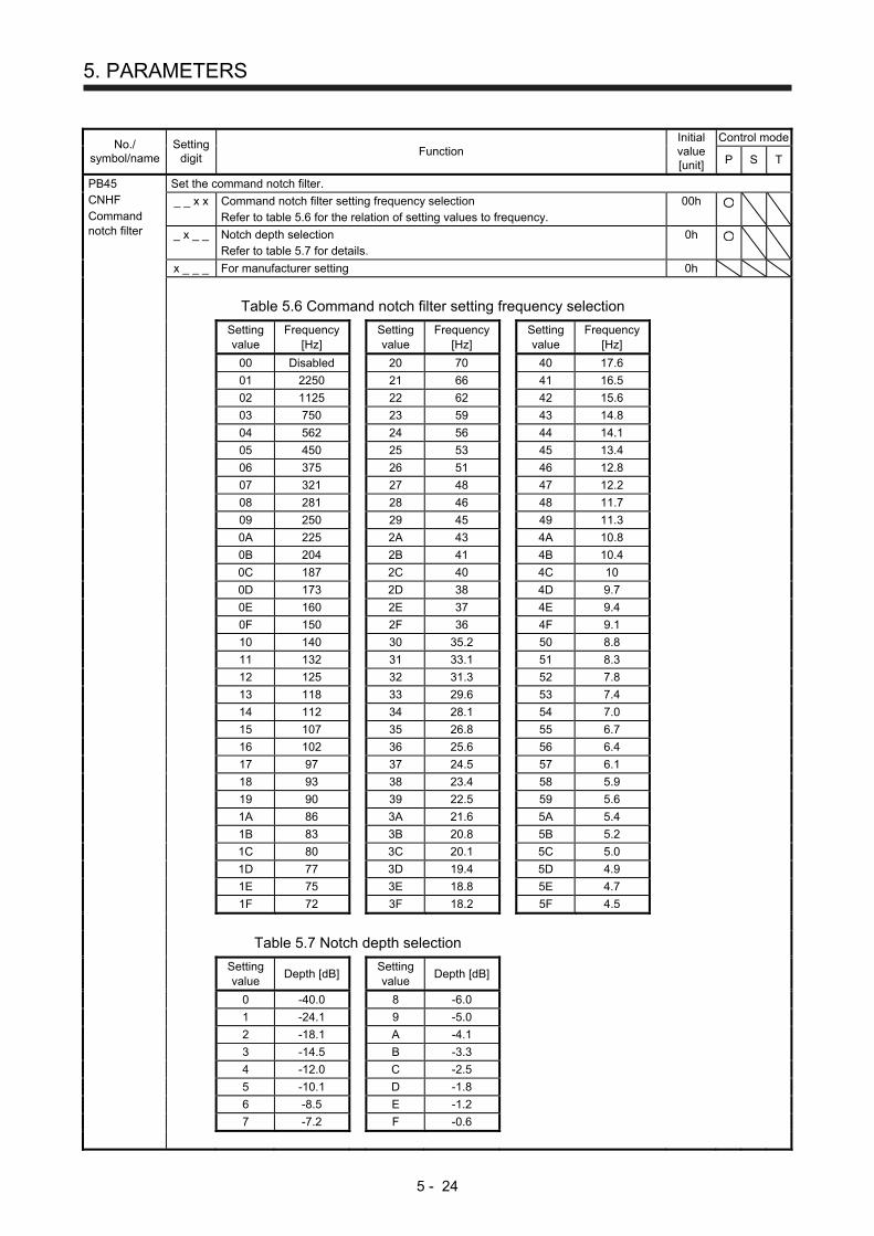
5. PARAMETERS
5 - 24
No./ symbol/name
Setting digit
Function Initial value [unit]
Control mode
P S T
PB45 CNHF Command notch filter
Set the command notch filter.
_ _ x x Command notch filter setting frequency selection Refer to table 5.6 for the relation of setting values to frequency.
00h
_ x _ _ Notch depth selection Refer to table 5.7 for details.
0h
x _ _ _ For manufacturer setting 0h
Table 5.6 Command notch filter setting frequency selection
Setting value
Frequency [Hz]
Setting value
Frequency [Hz]
Setting value
Frequency [Hz]
00 Disabled 20 70 40 17.6
01 2250 21 66 41 16.5
02 1125 22 62 42 15.6
03 750 23 59 43 14.8
04 562 24 56 44 14.1
05 450 25 53 45 13.4
06 375 26 51 46 12.8
07 321 27 48 47 12.2
08 281 28 46 48 11.7
09 250 29 45 49 11.3
0A 225 2A 43 4A 10.8
0B 204 2B 41 4B 10.4
0C 187 2C 40 4C 10
0D 173 2D 38 4D 9.7
0E 160 2E 37 4E 9.4
0F 150 2F 36 4F 9.1
10 140 30 35.2 50 8.8
11 132 31 33.1 51 8.3
12 125 32 31.3 52 7.8
13 118 33 29.6 53 7.4
14 112 34 28.1 54 7.0
15 107 35 26.8 55 6.7
16 102 36 25.6 56 6.4
17 97 37 24.5 57 6.1
18 93 38 23.4 58 5.9
19 90 39 22.5 59 5.6
1A 86 3A 21.6 5A 5.4
1B 83 3B 20.8 5B 5.2
1C 80 3C 20.1 5C 5.0
1D 77 3D 19.4 5D 4.9
1E 75 3E 18.8 5E 4.7
1F 72 3F 18.2 5F 4.5
Table 5.7 Notch depth selection
Setting value
Depth [dB] Setting value
Depth [dB]
0 -40.0 8 -6.0
1 -24.1 9 -5.0
2 -18.1 A -4.1
3 -14.5 B -3.3
4 -12.0 C -2.5
5 -10.1 D -1.8
6 -8.5 E -1.2
7 -7.2 F -0.6
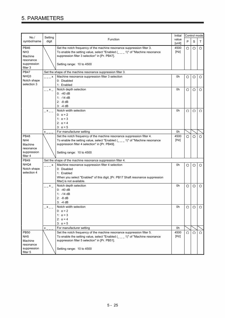
5. PARAMETERS
5 - 25
No./ symbol/name
Setting digit
Function Initial value [unit]
Control mode
P S T
PB46 NH3 Machine resonance suppression filter 3
Set the notch frequency of the machine resonance suppression filter 3. To enable the setting value, select "Enabled (_ _ _ 1)" of "Machine resonance suppression filter 3 selection" in [Pr. PB47]. Setting range: 10 to 4500
4500 [Hz]
PB47 NHQ3 Notch shape selection 3
Set the shape of the machine resonance suppression filter 3.
_ _ _ x Machine resonance suppression filter 3 selection 0: Disabled 1: Enabled
0h
_ _ x _ Notch depth selection 0: -40 dB 1: -14 dB 2: -8 dB 3: -4 dB
0h
_ x _ _ Notch width selection 0: α = 2 1: α = 3 2: α = 4 3: α = 5
0h
x _ _ _ For manufacturer setting 0h
PB48 NH4 Machine resonance suppression filter 4
Set the notch frequency of the machine resonance suppression filter 4. To enable the setting value, select "Enabled (_ _ _ 1)" of "Machine resonance suppression filter 4 selection" in [Pr. PB49]. Setting range: 10 to 4500
4500 [Hz]
PB49 NHQ4 Notch shape selection 4
Set the shape of the machine resonance suppression filter 4.
_ _ _ x Machine resonance suppression filter 4 selection 0: Disabled 1: Enabled When you select "Enabled" of this digit, [Pr. PB17 Shaft resonance suppression filter] is not available.
0h
_ _ x _ Notch depth selection 0: -40 dB 1: -14 dB 2: -8 dB 3: -4 dB
0h
_ x _ _ Notch width selection 0: α = 2 1: α = 3 2: α = 4 3: α = 5
0h
x _ _ _ For manufacturer setting 0h
PB50 NH5 Machine resonance suppression filter 5
Set the notch frequency of the machine resonance suppression filter 5. To enable the setting value, select "Enabled (_ _ _ 1)" of "Machine resonance suppression filter 5 selection" in [Pr. PB51]. Setting range: 10 to 4500
4500 [Hz]
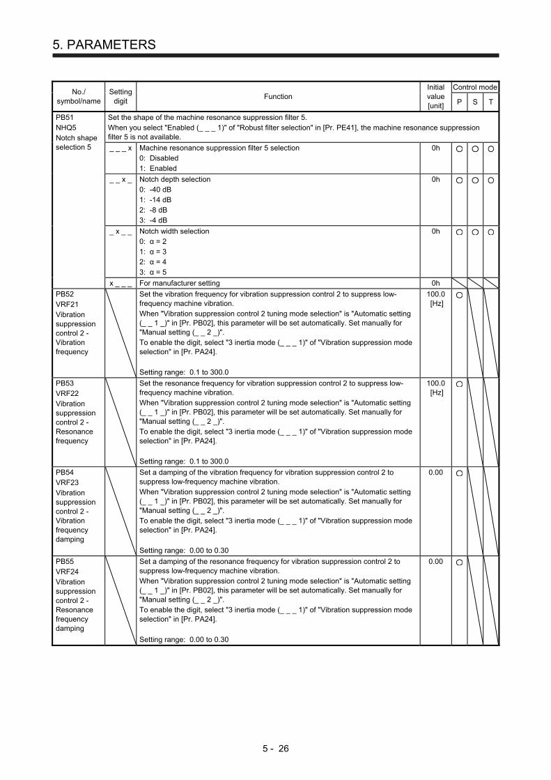
5. PARAMETERS
5 - 26
No./ symbol/name
Setting digit
Function Initial value [unit]
Control mode
P S T
PB51 NHQ5 Notch shape selection 5
Set the shape of the machine resonance suppression filter 5. When you select "Enabled (_ _ _ 1)" of "Robust filter selection" in [Pr. PE41], the machine resonance suppression filter 5 is not available.
_ _ _ x Machine resonance suppression filter 5 selection 0: Disabled 1: Enabled
0h
_ _ x _ Notch depth selection 0: -40 dB 1: -14 dB 2: -8 dB 3: -4 dB
0h
_ x _ _ Notch width selection 0: α = 2 1: α = 3 2: α = 4 3: α = 5
0h
x _ _ _ For manufacturer setting 0h
PB52 VRF21 Vibration suppression control 2 - Vibration frequency
Set the vibration frequency for vibration suppression control 2 to suppress low-frequency machine vibration. When "Vibration suppression control 2 tuning mode selection" is "Automatic setting (_ _ 1 _)" in [Pr. PB02], this parameter will be set automatically. Set manually for "Manual setting (_ _ 2 _)". To enable the digit, select "3 inertia mode (_ _ _ 1)" of "Vibration suppression mode selection" in [Pr. PA24]. Setting range: 0.1 to 300.0
100.0 [Hz]
PB53 VRF22 Vibration suppression control 2 - Resonance frequency
Set the resonance frequency for vibration suppression control 2 to suppress low-frequency machine vibration. When "Vibration suppression control 2 tuning mode selection" is "Automatic setting (_ _ 1 _)" in [Pr. PB02], this parameter will be set automatically. Set manually for "Manual setting (_ _ 2 _)". To enable the digit, select "3 inertia mode (_ _ _ 1)" of "Vibration suppression mode selection" in [Pr. PA24]. Setting range: 0.1 to 300.0
100.0 [Hz]
PB54 VRF23 Vibration suppression control 2 - Vibration frequency damping
Set a damping of the vibration frequency for vibration suppression control 2 to suppress low-frequency machine vibration. When "Vibration suppression control 2 tuning mode selection" is "Automatic setting (_ _ 1 _)" in [Pr. PB02], this parameter will be set automatically. Set manually for "Manual setting (_ _ 2 _)". To enable the digit, select "3 inertia mode (_ _ _ 1)" of "Vibration suppression mode selection" in [Pr. PA24]. Setting range: 0.00 to 0.30
0.00
PB55 VRF24 Vibration suppression control 2 - Resonance frequency damping
Set a damping of the resonance frequency for vibration suppression control 2 to suppress low-frequency machine vibration. When "Vibration suppression control 2 tuning mode selection" is "Automatic setting (_ _ 1 _)" in [Pr. PB02], this parameter will be set automatically. Set manually for "Manual setting (_ _ 2 _)". To enable the digit, select "3 inertia mode (_ _ _ 1)" of "Vibration suppression mode selection" in [Pr. PA24]. Setting range: 0.00 to 0.30
0.00
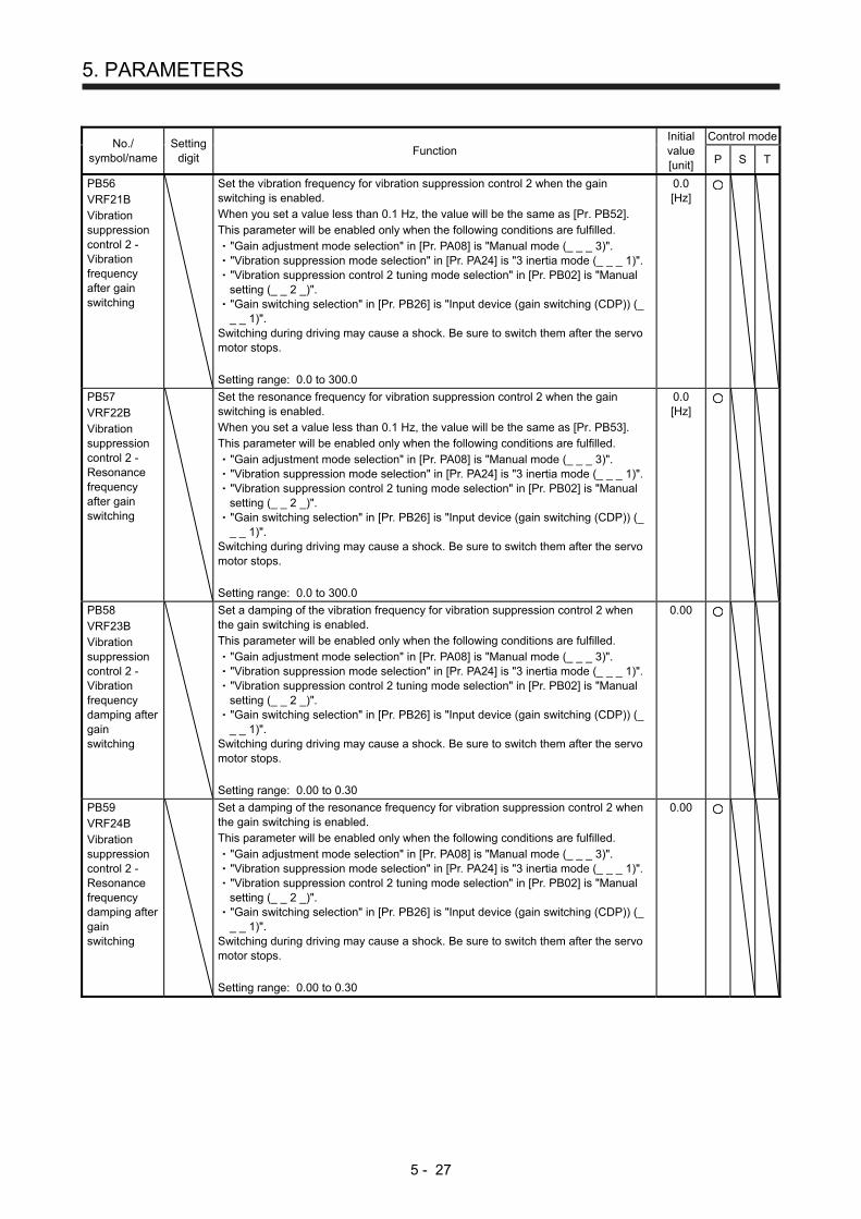
5. PARAMETERS
5 - 27
No./ symbol/name
Setting digit
Function Initial value [unit]
Control mode
P S T
PB56 VRF21B Vibration suppression control 2 - Vibration frequency after gain switching
Set the vibration frequency for vibration suppression control 2 when the gain switching is enabled. When you set a value less than 0.1 Hz, the value will be the same as [Pr. PB52]. This parameter will be enabled only when the following conditions are fulfilled.
"Gain adjustment mode selection" in [Pr. PA08] is "Manual mode (_ _ _ 3)". "Vibration suppression mode selection" in [Pr. PA24] is "3 inertia mode (_ _ _ 1)". "Vibration suppression control 2 tuning mode selection" in [Pr. PB02] is "Manual setting (_ _ 2 _)". "Gain switching selection" in [Pr. PB26] is "Input device (gain switching (CDP)) (_ _ _ 1)".
Switching during driving may cause a shock. Be sure to switch them after the servo motor stops. Setting range: 0.0 to 300.0
0.0 [Hz]
PB57 VRF22B Vibration suppression control 2 - Resonance frequency after gain switching
Set the resonance frequency for vibration suppression control 2 when the gain switching is enabled. When you set a value less than 0.1 Hz, the value will be the same as [Pr. PB53]. This parameter will be enabled only when the following conditions are fulfilled.
"Gain adjustment mode selection" in [Pr. PA08] is "Manual mode (_ _ _ 3)". "Vibration suppression mode selection" in [Pr. PA24] is "3 inertia mode (_ _ _ 1)". "Vibration suppression control 2 tuning mode selection" in [Pr. PB02] is "Manual setting (_ _ 2 _)". "Gain switching selection" in [Pr. PB26] is "Input device (gain switching (CDP)) (_ _ _ 1)".
Switching during driving may cause a shock. Be sure to switch them after the servo motor stops. Setting range: 0.0 to 300.0
0.0 [Hz]
PB58 VRF23B Vibration suppression control 2 - Vibration frequency damping after gain switching
Set a damping of the vibration frequency for vibration suppression control 2 when the gain switching is enabled. This parameter will be enabled only when the following conditions are fulfilled.
"Gain adjustment mode selection" in [Pr. PA08] is "Manual mode (_ _ _ 3)". "Vibration suppression mode selection" in [Pr. PA24] is "3 inertia mode (_ _ _ 1)". "Vibration suppression control 2 tuning mode selection" in [Pr. PB02] is "Manual setting (_ _ 2 _)". "Gain switching selection" in [Pr. PB26] is "Input device (gain switching (CDP)) (_ _ _ 1)".
Switching during driving may cause a shock. Be sure to switch them after the servo motor stops. Setting range: 0.00 to 0.30
0.00
PB59 VRF24B Vibration suppression control 2 - Resonance frequency damping after gain switching
Set a damping of the resonance frequency for vibration suppression control 2 when the gain switching is enabled. This parameter will be enabled only when the following conditions are fulfilled.
"Gain adjustment mode selection" in [Pr. PA08] is "Manual mode (_ _ _ 3)". "Vibration suppression mode selection" in [Pr. PA24] is "3 inertia mode (_ _ _ 1)". "Vibration suppression control 2 tuning mode selection" in [Pr. PB02] is "Manual setting (_ _ 2 _)". "Gain switching selection" in [Pr. PB26] is "Input device (gain switching (CDP)) (_ _ _ 1)".
Switching during driving may cause a shock. Be sure to switch them after the servo motor stops. Setting range: 0.00 to 0.30
0.00

5. PARAMETERS
5 - 28
No./ symbol/name
Setting digit
Function Initial value [unit]
Control mode
P S T
PB60 PG1B Model loop gain after gain switching
Set the model loop gain when the gain switching is enabled. When you set a value less than 1.0 rad/s, the value will be the same as [Pr. PB07]. This parameter will be enabled only when the following conditions are fulfilled.
"Gain adjustment mode selection" in [Pr. PA08] is "Manual mode (_ _ _ 3)". "Gain switching selection" in [Pr. PB26] is "Input device (gain switching (CDP)) (_ _ _ 1)".
Switching during driving may cause a shock. Be sure to switch them after the servo motor stops. Setting range: 0.0 to 2000.0
0.0 [rad/s]
5.2.3 Extension setting parameters ([Pr. PC_ _ ])
No./ symbol/name
Setting digit
Function Initial value [unit]
Control mode
P S T
PC01 STA Acceleration time constant
Set the acceleration time required to reach the rated speed from 0 r/min in response to VC (Analog speed command) and [Pr. PC05 Internal speed command 1] to [Pr. PC11 Internal speed command 7].
If the preset speed command is lowerthan the rated speed, acceleration/deceleration time will be shorter.
Time
[Pr. PC02] setting
0 r/min
Ratedspeed
Speed
[Pr. PC01] setting
For example for the servo motor of 3000 r/min rated speed, set 3000 (3s) to increase speed from 0 r/min to 1000 r/min in 1 second. Setting range: 0 to 50000
0 [ms]
PC02 STB Deceleration time constant
Set the deceleration time required to reach 0 r/min from the rated speed in response to VC (Analog speed command) and [Pr. PC05 Internal speed command 1] to [Pr. PC11 Internal speed command 7]. Setting range: 0 to 50000
0 [ms]

5. PARAMETERS
5 - 29
No./ symbol/name
Setting digit
Function Initial value [unit]
Control mode
P S T
PC03 STC S-pattern acceleration/ deceleration time constant
This is used to smooth start/stop of the servo motor. Set the time of the arc part for S-pattern acceleration/deceleration. Servo is usually operated with linear acceleration and deceleration; however, smooth start and stop are enabled by setting [Pr. PC03 S-pattern acceleration/deceleration time constants]. When the S-pattern acceleration/deceleration time constants are set, smooth positioning is enabled as shown in the following figure. Note that when it is set, a time period from the start to output of MEND (Travel completion) is longer by the S-pattern acceleration/ deceleration time constants.
Accelerationtime constant
Servo motorspeed
0 [r/min]
Decelerationtime constant
Ta
Ta + STC Tb
Tb + STC
Rated speed
Setting speed
Ta: Time of reaching tothe setting speed
Tb: Stopping time
When the STC value is set longer than the constant speed time, the speed may not reach to the command speed. Additionally, when 1000 ms or more value is set, it will be clamped to 1000 ms. Setting range: 0 to 5000
0 [ms]
PC04 TQC Torque command time constant
Set the constant of a primary delay to the torque command.
TQC TQC Time
Torque
Torque command
After filtering
TQC: Torque command time constant Setting range: 0 to 50000
0 [ms]
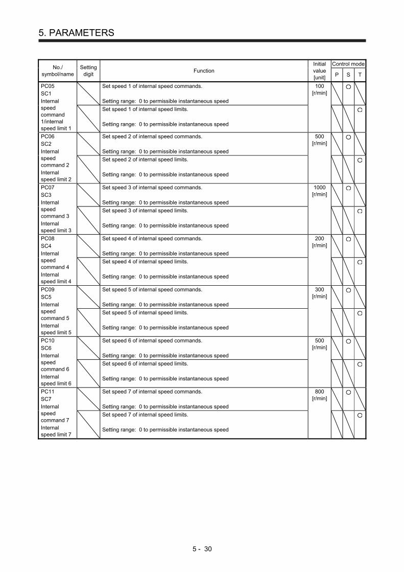
5. PARAMETERS
5 - 30
No./ symbol/name
Setting digit
Function Initial value [unit]
Control mode
P S T
PC05 SC1 Internal speed command 1/internal speed limit 1
Set speed 1 of internal speed commands. Setting range: 0 to permissible instantaneous speed
100 [r/min]
Set speed 1 of internal speed limits. Setting range: 0 to permissible instantaneous speed
PC06 SC2 Internal speed command 2 Internal speed limit 2
Set speed 2 of internal speed commands. Setting range: 0 to permissible instantaneous speed
500 [r/min]
Set speed 2 of internal speed limits. Setting range: 0 to permissible instantaneous speed
PC07 SC3 Internal speed command 3 Internal speed limit 3
Set speed 3 of internal speed commands. Setting range: 0 to permissible instantaneous speed
1000 [r/min]
Set speed 3 of internal speed limits. Setting range: 0 to permissible instantaneous speed
PC08 SC4 Internal speed command 4 Internal speed limit 4
Set speed 4 of internal speed commands. Setting range: 0 to permissible instantaneous speed
200 [r/min]
Set speed 4 of internal speed limits. Setting range: 0 to permissible instantaneous speed
PC09 SC5 Internal speed command 5 Internal speed limit 5
Set speed 5 of internal speed commands. Setting range: 0 to permissible instantaneous speed
300 [r/min]
Set speed 5 of internal speed limits. Setting range: 0 to permissible instantaneous speed
PC10 SC6 Internal speed command 6 Internal speed limit 6
Set speed 6 of internal speed commands. Setting range: 0 to permissible instantaneous speed
500 [r/min]
Set speed 6 of internal speed limits. Setting range: 0 to permissible instantaneous speed
PC11 SC7 Internal speed command 7 Internal speed limit 7
Set speed 7 of internal speed commands. Setting range: 0 to permissible instantaneous speed
800 [r/min]
Set speed 7 of internal speed limits. Setting range: 0 to permissible instantaneous speed
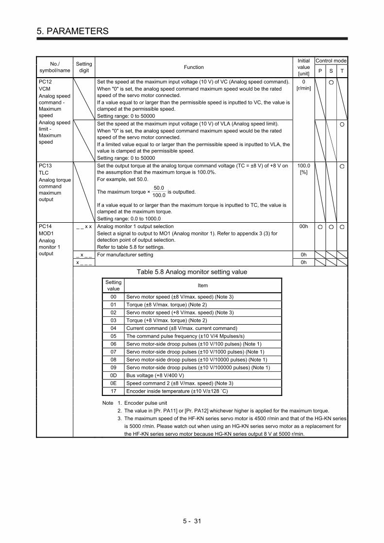
5. PARAMETERS
5 - 31
No./ symbol/name
Setting digit
Function Initial value [unit]
Control mode
P S T
PC12 VCM Analog speed command - Maximum speed Analog speed limit - Maximum speed
Set the speed at the maximum input voltage (10 V) of VC (Analog speed command). When "0" is set, the analog speed command maximum speed would be the rated speed of the servo motor connected. If a value equal to or larger than the permissible speed is inputted to VC, the value is clamped at the permissible speed. Setting range: 0 to 50000
0 [r/min]
Set the speed at the maximum input voltage (10 V) of VLA (Analog speed limit). When "0" is set, the analog speed command maximum speed would be the rated speed of the servo motor connected. If a limited value equal to or larger than the permissible speed is inputted to VLA, the value is clamped at the permissible speed. Setting range: 0 to 50000
PC13 TLC Analog torque command maximum output
Set the output torque at the analog torque command voltage (TC = ±8 V) of +8 V on the assumption that the maximum torque is 100.0%. For example, set 50.0.
The maximum torque ×
50.0
100.0 is outputted.
If a value equal to or larger than the maximum torque is inputted to TC, the value is clamped at the maximum torque. Setting range: 0.0 to 1000.0
100.0 [%]
PC14 MOD1 Analog monitor 1 output
_ _ x x Analog monitor 1 output selection Select a signal to output to MO1 (Analog monitor 1). Refer to appendix 3 (3) for detection point of output selection. Refer to table 5.8 for settings.
00h
_ x _ _ For manufacturer setting 0h
x _ _ _ 0h
Table 5.8 Analog monitor setting value
Setting value
Item
00 Servo motor speed (±8 V/max. speed) (Note 3)
01 Torque (±8 V/max. torque) (Note 2)
02 Servo motor speed (+8 V/max. speed) (Note 3)
03 Torque (+8 V/max. torque) (Note 2)
04 Current command (±8 V/max. current command)
05 The command pulse frequency (±10 V/4 Mpulses/s)
06 Servo motor-side droop pulses (±10 V/100 pulses) (Note 1)
07 Servo motor-side droop pulses (±10 V/1000 pulses) (Note 1)
08 Servo motor-side droop pulses (±10 V/10000 pulses) (Note 1)
09 Servo motor-side droop pulses (±10 V/100000 pulses) (Note 1)
0D Bus voltage (+8 V/400 V)
0E Speed command 2 (±8 V/max. speed) (Note 3)
17 Encoder inside temperature (±10 V/±128 ˚C)
Note 1. Encoder pulse unit
2. The value in [Pr. PA11] or [Pr. PA12] whichever higher is applied for the maximum torque. 3. The maximum speed of the HF-KN series servo motor is 4500 r/min and that of the HG-KN series
is 5000 r/min. Please watch out when using an HG-KN series servo motor as a replacement for
the HF-KN series servo motor because HG-KN series output 8 V at 5000 r/min.
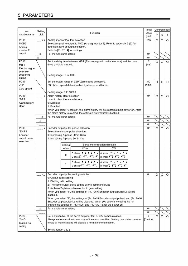
5. PARAMETERS
5 - 32
No./ symbol/name
Setting digit
Function Initial value [unit]
Control mode
P S T
PC15 MOD2 Analog monitor 2 output
_ _ x x Analog monitor 2 output selection Select a signal to output to MO2 (Analog monitor 2). Refer to appendix 3 (3) for detection point of output selection. Refer to [Pr. PC14] for settings.
01h
_ x _ _ For manufacturer setting 0h
x _ _ _ 0h
PC16 MBR Electromagnetic brake sequence output
Set the delay time between MBR (Electromagnetic brake interlock) and the base drive circuit is shut-off. Setting range: 0 to 1000
0 [ms]
PC17 ZSP Zero speed
Set the output range of ZSP (Zero speed detection). ZSP (Zero speed detection) has hysteresis of 20 r/min. Setting range: 0 to 10000
50 [r/min]
PC18 *BPS Alarm history clear
_ _ _ x Alarm history clear selection Used to clear the alarm history. 0: Disabled 1: Enabled When you select "Enabled", the alarm history will be cleared at next power-on. After the alarm history is cleared, the setting is automatically disabled.
0h
_ _ x _ For manufacturer setting 0h
_ x _ _ 0h
x _ _ _ 0h
PC19 *ENRS Encoder output pulse selection
_ _ _ x Encoder output pulse phase selection Select the encoder pulse direction. 0: Increasing A-phase 90° in CCW 1: Increasing A-phase 90° in CW
0h
Setting value
Servo motor rotation direction
CCW CW
0
A-phase
B-phase
A-phase
B-phase
1
A-phase
B-phase
A-phase
B-phase
_ _ x _ Encoder output pulse setting selection 0: Output pulse setting 1: Dividing ratio setting 2: The same output pulse setting as the command pulse 3: A-phase/B-phase pulse electronic gear setting When you select "1", the settings of [Pr. PA16 Encoder output pulses 2] will be disabled. When you select "2", the settings of [Pr. PA15 Encoder output pulses] and [Pr. PA16 Encoder output pulses 2] will be disabled. When you select the setting, do not change the settings in [Pr. PA06] and [Pr. PA07] after the power-on.
0h
_ x _ _ For manufacturer setting 0h
x _ _ _ 0h
PC20 *SNO Station No. setting
Set a station No. of the servo amplifier for RS-422 communication. Always set one station to one axis of the servo amplifier. Setting one station number to two or more stations will disable a normal communication. Setting range: 0 to 31
0 [Station]
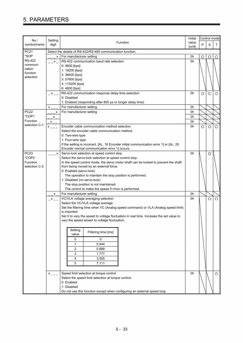
5. PARAMETERS
5 - 33
No./ symbol/name
Setting digit
Function Initial value [unit]
Control mode
P S T
PC21 *SOP RS-422 communi-cation function selection
Select the details of RS-422/RS-485 communication function.
_ _ _ x For manufacturer setting 0h
_ _ x _ RS-422 communication baud rate selection 0: 9600 [bps] 1: 19200 [bps] 2: 38400 [bps] 3: 57600 [bps] 4: 115200 [bps] 6: 4800 [bps]
0h
_ x _ _ RS-422 communication response delay time selection 0: Disabled 1: Enabled (responding after 800 μs or longer delay time)
0h
x _ _ _ For manufacturer setting 0h
PC22 *COP1 Function selection C-1
_ _ _ x For manufacturer setting 0h
_ _ x _ 2h
_ x _ _ 0h
x _ _ _ Encoder cable communication method selection Select the encoder cable communication method. 0: Two-wire type 1: Four-wire type If the setting is incorrect, [AL. 16 Encoder initial communication error 1] or [AL. 20 Encoder normal communication error 1] occurs.
0h
PC23 *COP2 Function selection C-2
_ _ _ x Servo-lock selection at speed control stop Select the servo-lock selection at speed control stop. In the speed control mode, the servo motor shaft can be locked to prevent the shaft from being moved by an external force. 0: Enabled (servo-lock)
The operation to maintain the stop position is performed. 1: Disabled (no servo-lock)
The stop position is not maintained. The control to make the speed 0 r/min is performed.
0h
_ _ x _ For manufacturer setting 0h
_ x _ _ VC/VLA voltage averaging selection Select the VC/VLA voltage average. Set the filtering time when VC (Analog speed command) or VLA (Analog speed limit) is imported. Set 0 to vary the speed to voltage fluctuation in real time. Increase the set value to vary the speed slower to voltage fluctuation.
0h
Setting value
Filtering time [ms]
0 0
1 0.444
2 0.888
3 1.777
4 3.555
5 7.111
x _ _ _ Speed limit selection at torque control Select the speed limit selection at torque control. 0: Enabled 1: Disabled Do not use this function except when configuring an external speed loop.
0h
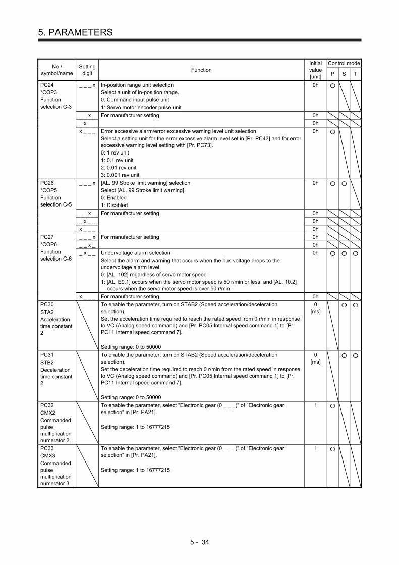
5. PARAMETERS
5 - 34
No./ symbol/name
Setting digit
Function Initial value [unit]
Control mode
P S T
PC24 *COP3 Function selection C-3
_ _ _ x In-position range unit selection Select a unit of in-position range. 0: Command input pulse unit 1: Servo motor encoder pulse unit
0h
_ _ x _ For manufacturer setting 0h
_ x _ _ 0h
x _ _ _ Error excessive alarm/error excessive warning level unit selection Select a setting unit for the error excessive alarm level set in [Pr. PC43] and for error excessive warning level setting with [Pr. PC73]. 0: 1 rev unit 1: 0.1 rev unit 2: 0.01 rev unit 3: 0.001 rev unit
0h
PC26 *COP5 Function selection C-5
_ _ _ x [AL. 99 Stroke limit warning] selection Select [AL. 99 Stroke limit warning]. 0: Enabled 1: Disabled
0h
_ _ x _ For manufacturer setting 0h
_ x _ _ 0h
x _ _ _ 0h
PC27 *COP6 Function selection C-6
_ _ _ x For manufacturer setting 0h
_ _ x _ 0h
_ x _ _ Undervoltage alarm selection Select the alarm and warning that occurs when the bus voltage drops to the undervoltage alarm level. 0: [AL. 102] regardless of servo motor speed 1: [AL. E9.1] occurs when the servo motor speed is 50 r/min or less, and [AL. 10.2]
occurs when the servo motor speed is over 50 r/min.
0h
x _ _ _ For manufacturer setting 0h
PC30 STA2 Acceleration time constant 2
To enable the parameter, turn on STAB2 (Speed acceleration/deceleration selection). Set the acceleration time required to reach the rated speed from 0 r/min in response to VC (Analog speed command) and [Pr. PC05 Internal speed command 1] to [Pr. PC11 Internal speed command 7]. Setting range: 0 to 50000
0 [ms]
PC31 STB2 Deceleration time constant 2
To enable the parameter, turn on STAB2 (Speed acceleration/deceleration selection). Set the deceleration time required to reach 0 r/min from the rated speed in response to VC (Analog speed command) and [Pr. PC05 Internal speed command 1] to [Pr. PC11 Internal speed command 7]. Setting range: 0 to 50000
0 [ms]
PC32 CMX2 Commanded pulse multiplication numerator 2
To enable the parameter, select "Electronic gear (0 _ _ _)" of "Electronic gear selection" in [Pr. PA21]. Setting range: 1 to 16777215
1
PC33 CMX3 Commanded pulse multiplication numerator 3
To enable the parameter, select "Electronic gear (0 _ _ _)" of "Electronic gear selection" in [Pr. PA21]. Setting range: 1 to 16777215
1
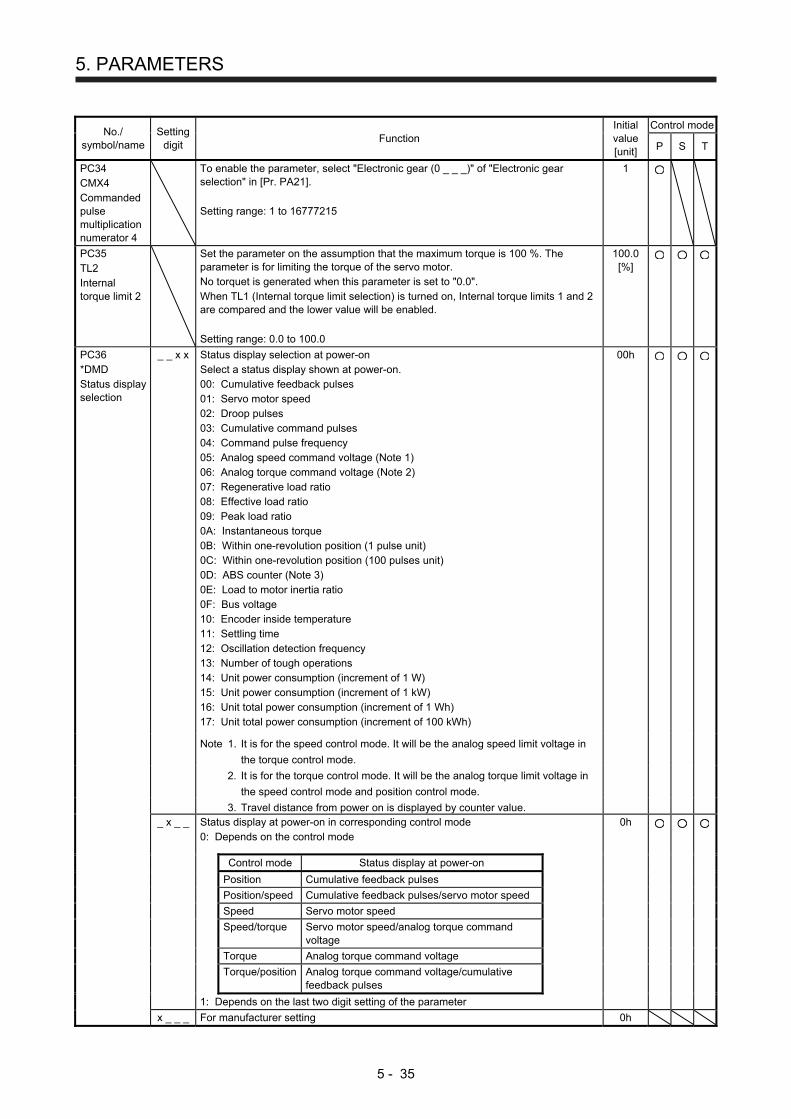
5. PARAMETERS
5 - 35
No./ symbol/name
Setting digit
Function Initial value [unit]
Control mode
P S T
PC34 CMX4 Commanded pulse multiplication numerator 4
To enable the parameter, select "Electronic gear (0 _ _ _)" of "Electronic gear selection" in [Pr. PA21]. Setting range: 1 to 16777215
1
PC35 TL2 Internal torque limit 2
Set the parameter on the assumption that the maximum torque is 100 %. The parameter is for limiting the torque of the servo motor. No torquet is generated when this parameter is set to "0.0". When TL1 (Internal torque limit selection) is turned on, Internal torque limits 1 and 2 are compared and the lower value will be enabled. Setting range: 0.0 to 100.0
100.0 [%]
PC36 *DMD Status display selection
_ _ x x Status display selection at power-on Select a status display shown at power-on. 00: Cumulative feedback pulses 01: Servo motor speed 02: Droop pulses 03: Cumulative command pulses 04: Command pulse frequency 05: Analog speed command voltage (Note 1) 06: Analog torque command voltage (Note 2) 07: Regenerative load ratio 08: Effective load ratio 09: Peak load ratio 0A: Instantaneous torque 0B: Within one-revolution position (1 pulse unit) 0C: Within one-revolution position (100 pulses unit) 0D: ABS counter (Note 3) 0E: Load to motor inertia ratio 0F: Bus voltage 10: Encoder inside temperature 11: Settling time 12: Oscillation detection frequency 13: Number of tough operations 14: Unit power consumption (increment of 1 W) 15: Unit power consumption (increment of 1 kW) 16: Unit total power consumption (increment of 1 Wh) 17: Unit total power consumption (increment of 100 kWh)
00h
Note 1. It is for the speed control mode. It will be the analog speed limit voltage in
the torque control mode.
2. It is for the torque control mode. It will be the analog torque limit voltage in
the speed control mode and position control mode.
3. Travel distance from power on is displayed by counter value.
_ x _ _ Status display at power-on in corresponding control mode 0: Depends on the control mode
0h
Control mode Status display at power-on
Position Cumulative feedback pulses
Position/speed Cumulative feedback pulses/servo motor speed
Speed Servo motor speed
Speed/torque Servo motor speed/analog torque command voltage
Torque Analog torque command voltage
Torque/position Analog torque command voltage/cumulative feedback pulses
1: Depends on the last two digit setting of the parameter
x _ _ _ For manufacturer setting 0h
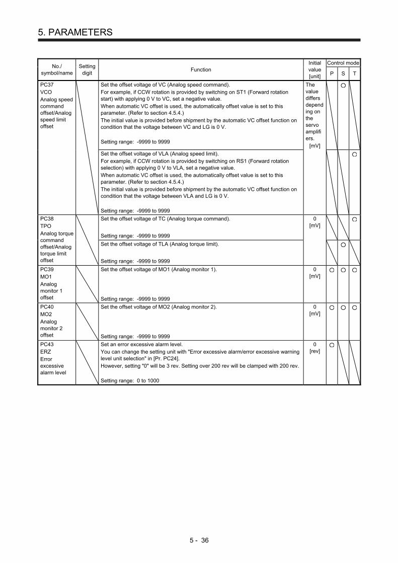
5. PARAMETERS
5 - 36
No./ symbol/name
Setting digit
Function Initial value [unit]
Control mode
P S T
PC37 VCO Analog speed command offset/Analog speed limit offset
Set the offset voltage of VC (Analog speed command). For example, if CCW rotation is provided by switching on ST1 (Forward rotation start) with applying 0 V to VC, set a negative value. When automatic VC offset is used, the automatically offset value is set to this parameter. (Refer to section 4.5.4.) The initial value is provided before shipment by the automatic VC offset function on condition that the voltage between VC and LG is 0 V. Setting range: -9999 to 9999
The value differs depending on the servo amplifiers.
[mV]
Set the offset voltage of VLA (Analog speed limit). For example, if CCW rotation is provided by switching on RS1 (Forward rotation selection) with applying 0 V to VLA, set a negative value. When automatic VC offset is used, the automatically offset value is set to this parameter. (Refer to section 4.5.4.) The initial value is provided before shipment by the automatic VC offset function on condition that the voltage between VLA and LG is 0 V. Setting range: -9999 to 9999
PC38 TPO Analog torque command offset/Analog torque limit offset
Set the offset voltage of TC (Analog torque command).
Setting range: -9999 to 9999
0 [mV]
Set the offset voltage of TLA (Analog torque limit).
Setting range: -9999 to 9999
PC39 MO1 Analog monitor 1 offset
Set the offset voltage of MO1 (Analog monitor 1). Setting range: -9999 to 9999
0 [mV]
PC40 MO2 Analog monitor 2 offset
Set the offset voltage of MO2 (Analog monitor 2). Setting range: -9999 to 9999
0 [mV]
PC43 ERZ Error excessive alarm level
Set an error excessive alarm level. You can change the setting unit with "Error excessive alarm/error excessive warning level unit selection" in [Pr. PC24]. However, setting "0" will be 3 rev. Setting over 200 rev will be clamped with 200 rev. Setting range: 0 to 1000
0 [rev]
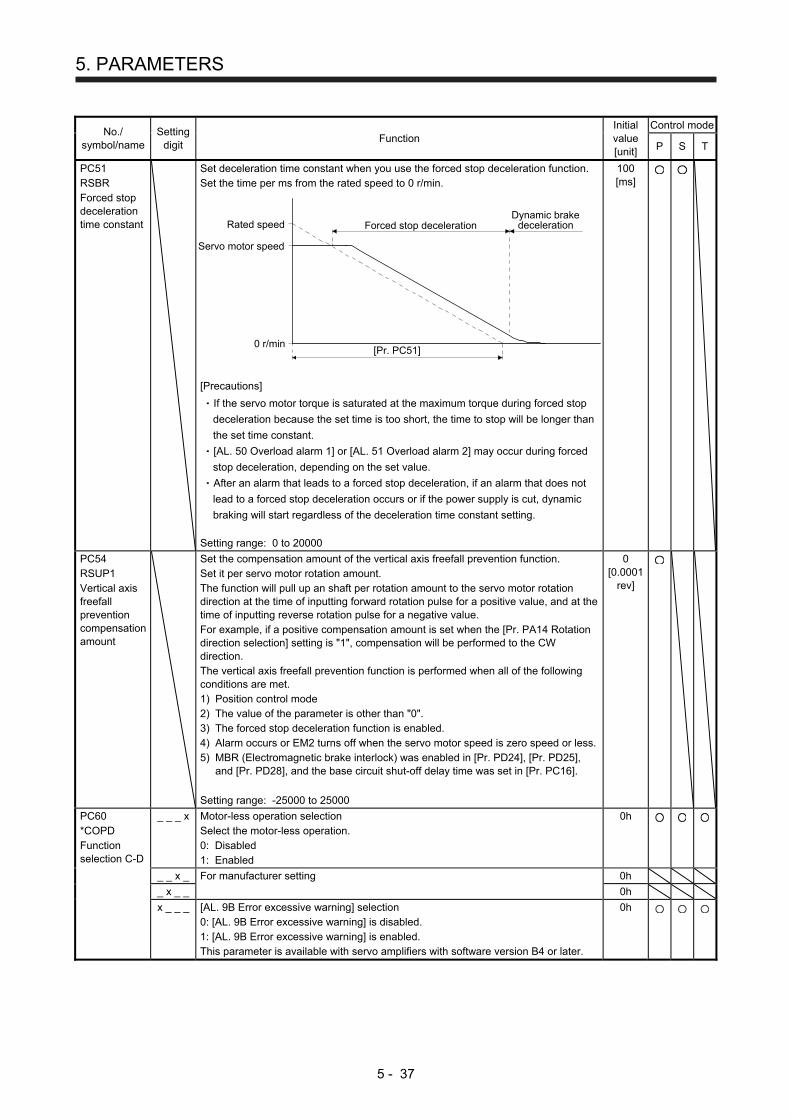
5. PARAMETERS
5 - 37
No./ symbol/name
Setting digit
Function Initial value [unit]
Control mode
P S T
PC51 RSBR Forced stop deceleration time constant
Set deceleration time constant when you use the forced stop deceleration function. Set the time per ms from the rated speed to 0 r/min.
Forced stop deceleration
[Pr. PC51]0 r/min
Servo motor speed
Rated speedDynamic brake
deceleration
[Precautions]
If the servo motor torque is saturated at the maximum torque during forced stop
deceleration because the set time is too short, the time to stop will be longer than
the set time constant.
[AL. 50 Overload alarm 1] or [AL. 51 Overload alarm 2] may occur during forced
stop deceleration, depending on the set value.
After an alarm that leads to a forced stop deceleration, if an alarm that does not
lead to a forced stop deceleration occurs or if the power supply is cut, dynamic
braking will start regardless of the deceleration time constant setting. Setting range: 0 to 20000
100 [ms]
PC54 RSUP1 Vertical axis freefall prevention compensation amount
Set the compensation amount of the vertical axis freefall prevention function. Set it per servo motor rotation amount. The function will pull up an shaft per rotation amount to the servo motor rotation direction at the time of inputting forward rotation pulse for a positive value, and at the time of inputting reverse rotation pulse for a negative value. For example, if a positive compensation amount is set when the [Pr. PA14 Rotation direction selection] setting is "1", compensation will be performed to the CW direction. The vertical axis freefall prevention function is performed when all of the following conditions are met. 1) Position control mode 2) The value of the parameter is other than "0". 3) The forced stop deceleration function is enabled. 4) Alarm occurs or EM2 turns off when the servo motor speed is zero speed or less. 5) MBR (Electromagnetic brake interlock) was enabled in [Pr. PD24], [Pr. PD25],
and [Pr. PD28], and the base circuit shut-off delay time was set in [Pr. PC16]. Setting range: -25000 to 25000
0 [0.0001
rev]
PC60 *COPD Function selection C-D
_ _ _ x Motor-less operation selection Select the motor-less operation. 0: Disabled 1: Enabled
0h
_ _ x _ For manufacturer setting 0h
_ x _ _ 0h
x _ _ _ [AL. 9B Error excessive warning] selection 0: [AL. 9B Error excessive warning] is disabled. 1: [AL. 9B Error excessive warning] is enabled. This parameter is available with servo amplifiers with software version B4 or later.
0h
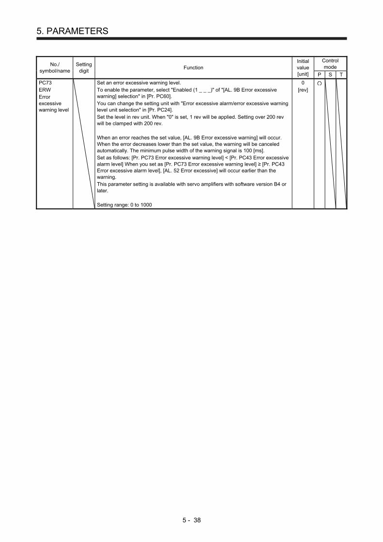
5. PARAMETERS
5 - 38
No./ symbol/name
Setting digit
Function Initial value [unit]
Control mode
P S T
PC73 ERW Error excessive warning level
Set an error excessive warning level. To enable the parameter, select "Enabled (1 _ _ _)" of "[AL. 9B Error excessive warning] selection" in [Pr. PC60]. You can change the setting unit with "Error excessive alarm/error excessive warning level unit selection" in [Pr. PC24]. Set the level in rev unit. When "0" is set, 1 rev will be applied. Setting over 200 rev will be clamped with 200 rev. When an error reaches the set value, [AL. 9B Error excessive warning] will occur. When the error decreases lower than the set value, the warning will be canceled automatically. The minimum pulse width of the warning signal is 100 [ms]. Set as follows: [Pr. PC73 Error excessive warning level] < [Pr. PC43 Error excessive alarm level] When you set as [Pr. PC73 Error excessive warning level] ≥ [Pr. PC43 Error excessive alarm level], [AL. 52 Error excessive] will occur earlier than the warning. This parameter setting is available with servo amplifiers with software version B4 or later. Setting range: 0 to 1000
0 [rev]
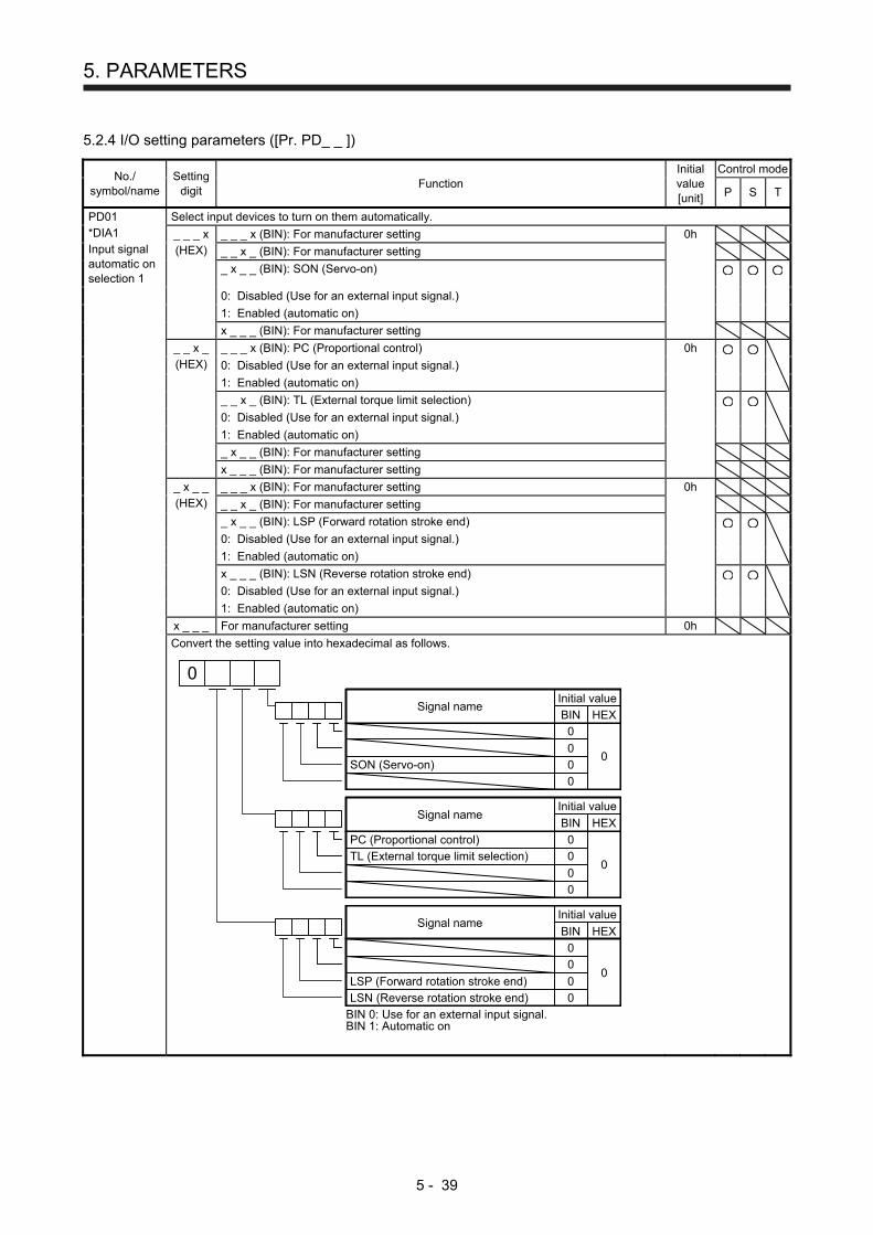
5. PARAMETERS
5 - 39
5.2.4 I/O setting parameters ([Pr. PD_ _ ])
No./ symbol/name
Setting digit
Function Initial value [unit]
Control mode
P S T
PD01 *DIA1 Input signal automatic on selection 1
Select input devices to turn on them automatically.
_ _ _ x (HEX)
_ _ _ x (BIN): For manufacturer setting 0h
_ _ x _ (BIN): For manufacturer setting
_ x _ _ (BIN): SON (Servo-on)
0: Disabled (Use for an external input signal.)
1: Enabled (automatic on)
x _ _ _ (BIN): For manufacturer setting
_ _ x _ (HEX)
_ _ _ x (BIN): PC (Proportional control) 0h
0: Disabled (Use for an external input signal.)
1: Enabled (automatic on)
_ _ x _ (BIN): TL (External torque limit selection)
0: Disabled (Use for an external input signal.)
1: Enabled (automatic on)
_ x _ _ (BIN): For manufacturer setting
x _ _ _ (BIN): For manufacturer setting
_ x _ _ (HEX)
_ _ _ x (BIN): For manufacturer setting 0h
_ _ x _ (BIN): For manufacturer setting
_ x _ _ (BIN): LSP (Forward rotation stroke end)
0: Disabled (Use for an external input signal.)
1: Enabled (automatic on)
x _ _ _ (BIN): LSN (Reverse rotation stroke end)
0: Disabled (Use for an external input signal.)
1: Enabled (automatic on)
x _ _ _ For manufacturer setting 0h
Convert the setting value into hexadecimal as follows.
0
Initial value
BIN HEXSignal name
0
0
0
0
0
SON (Servo-on)
0
Initial value
BIN HEXSignal name
0
0
0
0
PC (Proportional control)
TL (External torque limit selection)
0
BIN 0: Use for an external input signal.BIN 1: Automatic on
Initial value
BIN HEXSignal name
0
0
0
0
LSP (Forward rotation stroke end)
LSN (Reverse rotation stroke end)
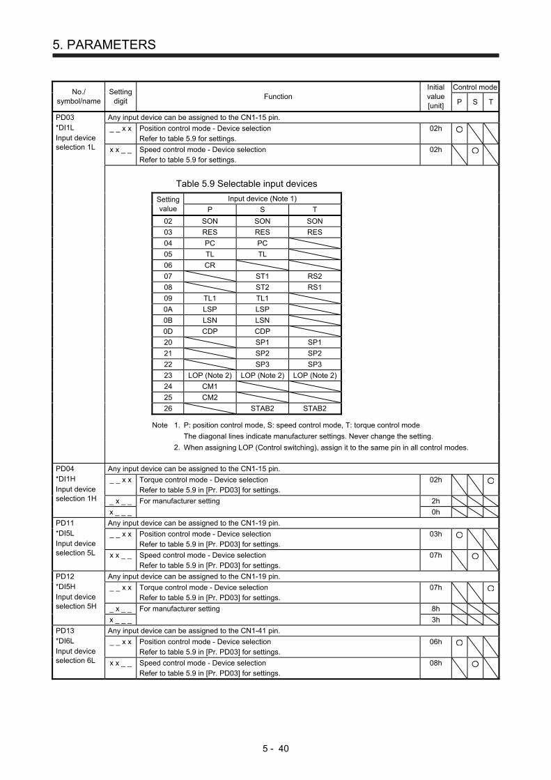
5. PARAMETERS
5 - 40
No./ symbol/name
Setting digit
Function Initial value [unit]
Control mode
P S T
PD03 *DI1L Input device selection 1L
Any input device can be assigned to the CN1-15 pin.
_ _ x x Position control mode - Device selection Refer to table 5.9 for settings.
02h
x x _ _ Speed control mode - Device selection Refer to table 5.9 for settings.
02h
Table 5.9 Selectable input devices
Setting value
Input device (Note 1)
P S T
02 SON SON SON
03 RES RES RES
04 PC PC
05 TL TL
06 CR
07 ST1 RS2
08 ST2 RS1
09 TL1 TL1
0A LSP LSP
0B LSN LSN
0D CDP CDP
20 SP1 SP1
21 SP2 SP2
22 SP3 SP3
23 LOP (Note 2) LOP (Note 2) LOP (Note 2)
24 CM1
25 CM2
26 STAB2 STAB2
Note 1. P: position control mode, S: speed control mode, T: torque control mode
The diagonal lines indicate manufacturer settings. Never change the setting. 2. When assigning LOP (Control switching), assign it to the same pin in all control modes.
PD04 *DI1H Input device selection 1H
Any input device can be assigned to the CN1-15 pin.
_ _ x x Torque control mode - Device selection Refer to table 5.9 in [Pr. PD03] for settings.
02h
_ x _ _ For manufacturer setting 2h
x _ _ _ 0h
PD11 *DI5L Input device selection 5L
Any input device can be assigned to the CN1-19 pin.
_ _ x x Position control mode - Device selection Refer to table 5.9 in [Pr. PD03] for settings.
03h
x x _ _ Speed control mode - Device selection Refer to table 5.9 in [Pr. PD03] for settings.
07h
PD12 *DI5H Input device selection 5H
Any input device can be assigned to the CN1-19 pin.
_ _ x x Torque control mode - Device selection Refer to table 5.9 in [Pr. PD03] for settings.
07h
_ x _ _ For manufacturer setting 8h
x _ _ _ 3h
PD13 *DI6L Input device selection 6L
Any input device can be assigned to the CN1-41 pin.
_ _ x x Position control mode - Device selection Refer to table 5.9 in [Pr. PD03] for settings.
06h
x x _ _ Speed control mode - Device selection Refer to table 5.9 in [Pr. PD03] for settings.
08h

5. PARAMETERS
5 - 41
No./ symbol/name
Setting digit
Function Initial value [unit]
Control mode
P S T
PD14 *DI6H Input device selection 6H
Any input device can be assigned to the CN1-41 pin.
_ _ x x Torque control mode - Device selection Refer to table 5.9 in [Pr. PD03] for settings.
08h
_ x _ _ For manufacturer setting 9h
x _ _ _ 3h
PD17 *DI8L Input device selection 8L
Any input device can be assigned to the CN1-43 pin.
_ _ x x Position control mode - Device selection Refer to table 5.9 in [Pr. PD03] for settings.
0Ah
x x _ _ Speed control mode - Device selection Refer to table 5.9 in [Pr. PD03] for settings.
0Ah
PD18 *DI8H Input device selection 8H
Any input device can be assigned to the CN1-43 pin.
_ _ x x Torque control mode - Device selection Refer to table 5.9 in [Pr. PD03] for settings.
00h
_ x _ _ For manufacturer setting 7h
x _ _ _ 0h
PD19 *DI9L Input device selection 9L
Any input device can be assigned to the CN1-44 pin.
_ _ x x Position control mode - Device selection Refer to table 5.9 in [Pr. PD03] for settings.
0Bh
x x _ _ Speed control mode - Device selection Refer to table 5.9 in [Pr. PD03] for settings.
0Bh
PD20 *DI9H Input device selection 9H
Any input device can be assigned to the CN1-44 pin.
_ _ x x Torque control mode - Device selection Refer to table 5.9 in [Pr. PD03] for settings.
00h
_ x _ _ For manufacturer setting 8h
x _ _ _ 0h
PD24 *DO2 Output device selection 2
_ _ x x Device selection Any output device can be assigned to the CN1-23 pin. Refer to table 5.10 for settings.
0Ch
_ x _ _ For manufacturer setting 0h
x _ _ _ 0h
Table 5.10 Selectable output devices
Setting value
Output device (Note)
P S T
00 Always off Always off Always off
02 RD RD RD
03 ALM ALM ALM
04 INP SA Always off
05 MBR MBR MBR
07 TLC TLC VLC
08 WNG WNG WNG
0A Always off SA Always off
0B Always off Always off VLC
0C ZSP ZSP ZSP
0D MTTR MTTR MTTR
0F CDPS Always off Always off
Note. P: position control mode, S: speed control mode, T: torque control mode

5. PARAMETERS
5 - 42
No./ symbol/name
Setting digit
Function Initial value [unit]
Control mode
P S T
PD25 *DO3 Output device selection 3
_ _ x x Device selection Any output device can be assigned to the CN1-24 pin. Refer to table 5.10 in [Pr. PD24] for settings.
04h
_ x _ _ For manufacturer setting 0h
x _ _ _ 0h
PD28 *DO6 Output device selection 6
_ _ x x Device selection Any output device can be assigned to the CN1-49 pin. Refer to table 5.10 in [Pr. PD24] for settings.
02h
_ x _ _ For manufacturer setting 0h
x _ _ _ 0h
PD29 *DIF Input filter setting
Select a filter for the input signal.
_ _ _ x Input signal filter selection If external input signal causes chattering due to noise, etc., input filter is used to suppress it. 0: None 1: 0.888 [ms] 2: 1.777 [ms] 3: 2.666 [ms] 4: 3.555 [ms]
4h
_ _ x _ RES (Reset) dedicated filter selection 0: Disabled 1: Enabled (50 [ms])
0h
_ x _ _ CR (Clear) dedicated filter selection 0: Disabled 1: Enabled (50 [ms])
0h
x _ _ _ For manufacturer setting 0h
PD30 *DOP1 Function selection D-1
_ _ _ x Stop method selection for LSP (Forward rotation stroke end) off and LSN (Reverse rotation stroke end) off Select a stop method for LSP (Forward rotation stroke end) off and LSN (Reverse rotation stroke end) off 0: Quick stop 1: Slow stop
0h
_ _ x _ Base circuit status selection for RES (Reset) on 0: Base circuit shut-off 1: No base circuit shut-off
0h
_ x _ _ For manufacturer setting 0h
x _ _ _ 0h
PD32 *DOP3 Function selection D-3
_ _ _ x CR (Clear) selection Set CR (Clear). 0: Deleting droop pulses at the leading edge of turning on of CR 1: Continuous deleting of droop pulses while CR is on
0h
_ _ x _ For manufacturer setting 0h
_ x _ _ 0h
x _ _ _ 0h
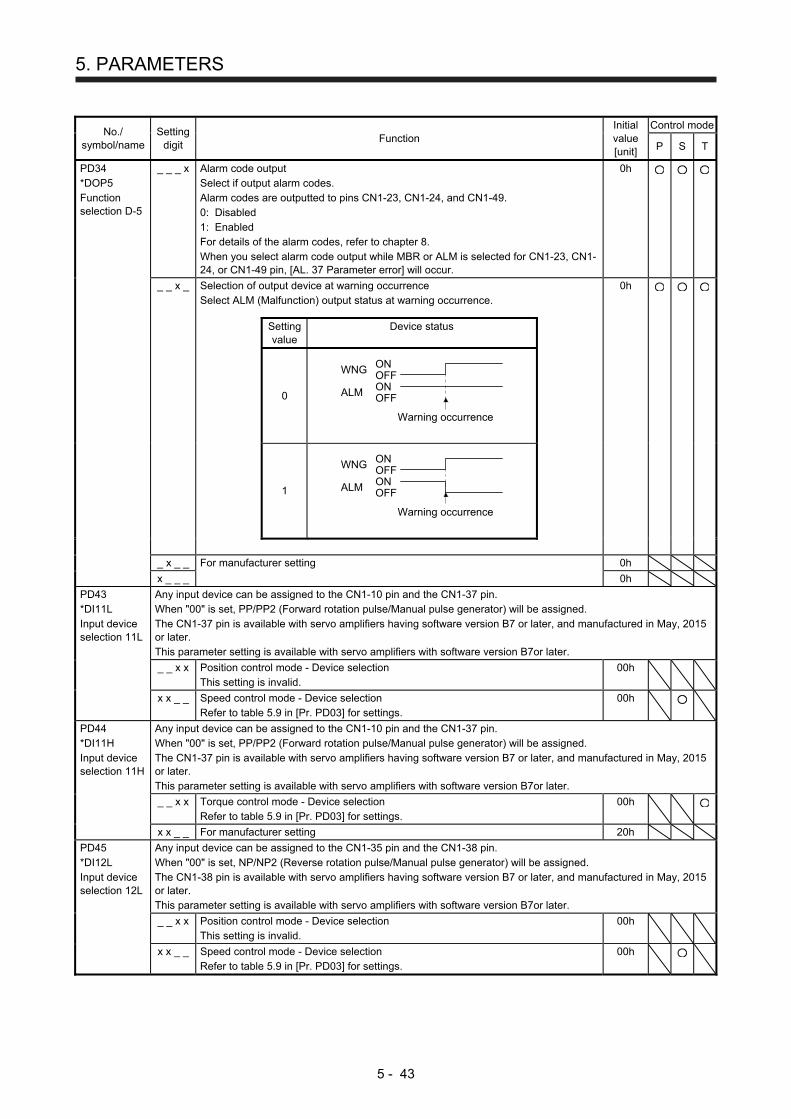
5. PARAMETERS
5 - 43
No./ symbol/name
Setting digit
Function Initial value [unit]
Control mode
P S T
PD34 *DOP5 Function selection D-5
_ _ _ x Alarm code output Select if output alarm codes. Alarm codes are outputted to pins CN1-23, CN1-24, and CN1-49. 0: Disabled 1: Enabled For details of the alarm codes, refer to chapter 8. When you select alarm code output while MBR or ALM is selected for CN1-23, CN1-24, or CN1-49 pin, [AL. 37 Parameter error] will occur.
0h
_ _ x _ Selection of output device at warning occurrence Select ALM (Malfunction) output status at warning occurrence.
0h
Setting value
Device status
0
OFFON
OFFON
WNG
ALM
Warning occurrence
1
OFFON
OFFON
WNG
ALM
Warning occurrence
_ x _ _ For manufacturer setting 0h
x _ _ _ 0h
PD43 *DI11L Input device selection 11L
Any input device can be assigned to the CN1-10 pin and the CN1-37 pin. When "00" is set, PP/PP2 (Forward rotation pulse/Manual pulse generator) will be assigned. The CN1-37 pin is available with servo amplifiers having software version B7 or later, and manufactured in May, 2015 or later. This parameter setting is available with servo amplifiers with software version B7or later.
_ _ x x Position control mode - Device selection This setting is invalid.
00h
x x _ _ Speed control mode - Device selection Refer to table 5.9 in [Pr. PD03] for settings.
00h
PD44 *DI11H Input device selection 11H
Any input device can be assigned to the CN1-10 pin and the CN1-37 pin. When "00" is set, PP/PP2 (Forward rotation pulse/Manual pulse generator) will be assigned. The CN1-37 pin is available with servo amplifiers having software version B7 or later, and manufactured in May, 2015 or later. This parameter setting is available with servo amplifiers with software version B7or later.
_ _ x x Torque control mode - Device selection Refer to table 5.9 in [Pr. PD03] for settings.
00h
x x _ _ For manufacturer setting 20h
PD45 *DI12L Input device selection 12L
Any input device can be assigned to the CN1-35 pin and the CN1-38 pin. When "00" is set, NP/NP2 (Reverse rotation pulse/Manual pulse generator) will be assigned. The CN1-38 pin is available with servo amplifiers having software version B7 or later, and manufactured in May, 2015 or later. This parameter setting is available with servo amplifiers with software version B7or later.
_ _ x x Position control mode - Device selection This setting is invalid.
00h
x x _ _ Speed control mode - Device selection Refer to table 5.9 in [Pr. PD03] for settings.
00h

5. PARAMETERS
5 - 44
No./ symbol/name
Setting digit
Function Initial value [unit]
Control mode
P S T
PD46 *DI12H Input device selection 12H
Any input device can be assigned to the CN1-35 pin and the CN1-38 pin. When "00" is set, NP/NP2 (Reverse rotation pulse/Manual pulse generator) will be assigned. The CN1-38 pin is available with servo amplifiers having software version B7 or later, and manufactured in May, 2015 or later. This parameter setting is available with servo amplifiers with software version B7or later.
_ _ x x Torque control mode - Device selection Refer to table 5.9 in [Pr. PD03] for settings.
00h
x x _ _ For manufacturer setting 2Bh
5.2.5 Extension setting 2 parameters ([Pr. PE_ _ ])
No./ symbol/name
Setting digit
Function Initial value [unit]
Control mode
P S T
PE41 EOP3 Function selection E-3
_ _ _ x Robust filter selection 0: Disabled 1: Enabled When you select "Enabled" of this digit, the machine resonance suppression filter 5 set in [Pr. PB51] is not available.
0h
_ _ x _ For manufacturer setting 0h
_ x _ _ 0h
x _ _ _ 0h
5.2.6 Extension setting 3 parameters ([Pr. PF_ _ ])
No./ symbol/name
Setting digit
Function Initial value [unit]
Control mode
P S T
PF09 *FOP5 Function selection F-5
_ _ _ x Electronic dynamic brake selection 0: Disabled 3: Automatic (enabled only for specified servo motors) Refer to the following table for the specified servo motors.
0h
Series Servo motor
HG-KN HG-KN053/HG-KN13/HG-KN23/HG-KN43
HG-SN HG-SN52
This parameter setting is available with servo amplifiers with software version B5 or later.
_ _ x _ For manufacturer setting 0h
_ x _ _ 0h
x _ _ _ 0h
PF21 DRT Drive recorder switching time setting
Set a drive recorder switching time. When a USB communication is cut during using a graph function or a graph function is terminated, the function will be changed to the drive recorder function after the setting time of this parameter. When a value from "1" to "32767" is set, it will switch after the setting value. When "0" is set, it will switch after 600 s. When "-1" is set, the drive recorder function is disabled. Setting range: -1 to 32767
0 [s]

5. PARAMETERS
5 - 45
No./ symbol/name
Setting digit
Function Initial value [unit]
Control mode
P S T
PF23 OSCL1 Vibration tough drive - Oscillation detection level
Set a filter readjustment sensitivity of [Pr. PB13 Machine resonance suppression filter 1] and [Pr. PB15 Machine resonance suppression filter 2] while the vibration tough drive is enabled. However, setting "0" will be 50%. Example: When you set "50" to the parameter, the filter will be readjusted at the time of 50% or more oscillation level. Setting range: 0 to 100
50 [%]
PF24 *OSCL2 Vibration tough drive function selection
_ _ _ x Oscillation detection alarm selection Select alarm or warning when an oscillation continues at a filter readjustment sensitivity level of [Pr. PF23]. The digit is continuously enabled regardless of the vibration tough drive in [Pr. PA20]. 0: [AL. 54 Oscillation detection] will occur at oscillation detection. 1: [AL. F3.1 Oscillation detection warning] will occur at oscillation detection. 2: Oscillation detection function disabled
0h
_ _ x _ For manufacturer setting 0h
_ x _ _ 0h
x _ _ _ 0h
PF25 CVAT instantaneous power failure tough drive - detection time
Set the time of the [AL. 10.1 Voltage drop in the power] occurrence. To disable the parameter, select "Disabled (_ 0 _ _)" of "Instantaneous power failure tough drive selection" in [Pr. PA20]. When "Enabled (_ 1 _ _)" is selected of "Instantaneous power failure tough drive selection" in [Pr. PA20], the power should be off for the setting value of this parameter + 1.5 s or more before cycling the power to enable a parameter whose symbol is preceded by "*". Setting range: 30 to 2000
200 [ms]
PF31 FRIC Machine diagnosis function - Friction judgement speed
Set a servo motor speed to divide a friction estimation area into high and low for the friction estimation process of the machine diagnosis. However, setting "0" will be the value half of the rated speed. When your operation pattern is under rated speed, we recommend that you set half value to the maximum speed with this.
Maximum speed in operation
[Pr. PF31] setting
Operation pattern
0 r/minServo motorspeed
Forward rotationdirection
Reverse rotationdirection
Setting range: 0 to permissible speed
0 [r/min]

5. PARAMETERS
5 - 46
MEMO
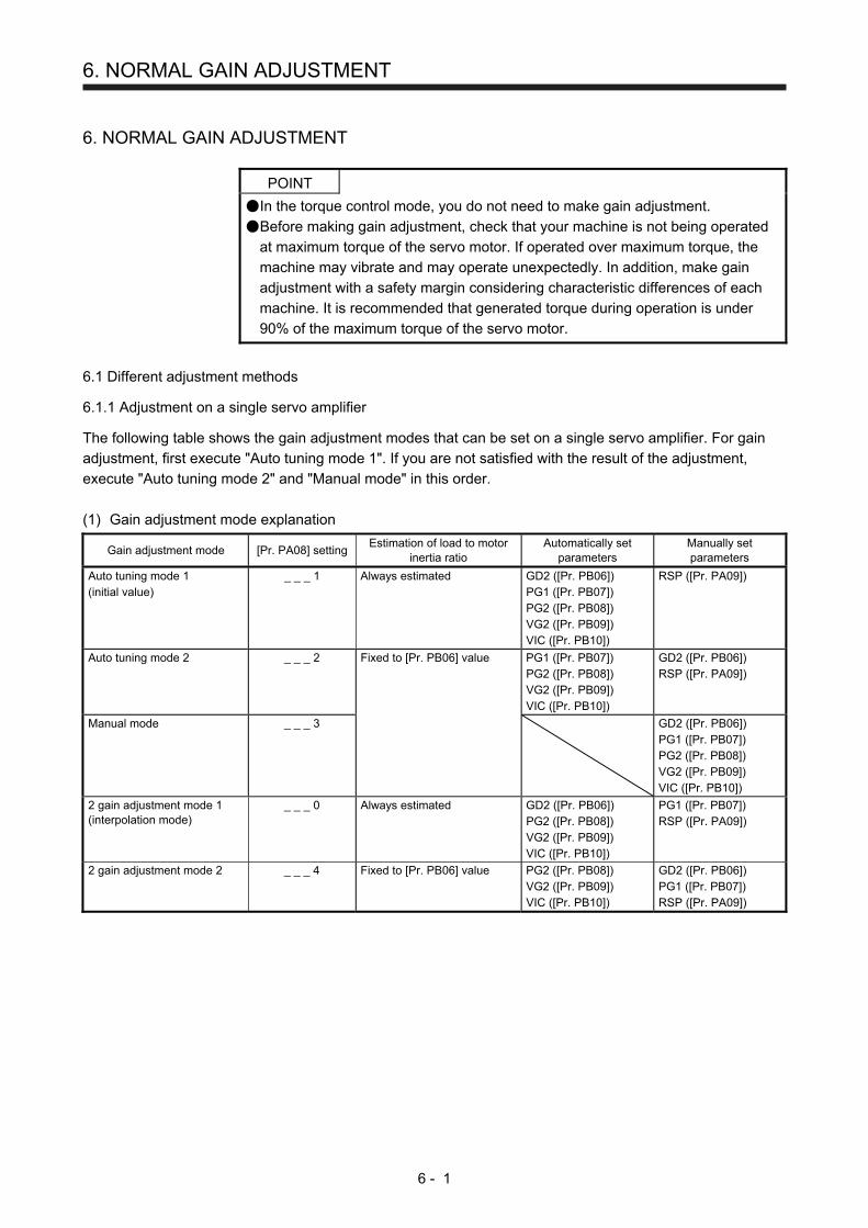
6. NORMAL GAIN ADJUSTMENT
6 - 1
6. NORMAL GAIN ADJUSTMENT
POINT
In the torque control mode, you do not need to make gain adjustment.
Before making gain adjustment, check that your machine is not being operated
at maximum torque of the servo motor. If operated over maximum torque, the
machine may vibrate and may operate unexpectedly. In addition, make gain
adjustment with a safety margin considering characteristic differences of each
machine. It is recommended that generated torque during operation is under
90% of the maximum torque of the servo motor.
6.1 Different adjustment methods
6.1.1 Adjustment on a single servo amplifier
The following table shows the gain adjustment modes that can be set on a single servo amplifier. For gain
adjustment, first execute "Auto tuning mode 1". If you are not satisfied with the result of the adjustment,
execute "Auto tuning mode 2" and "Manual mode" in this order.
(1) Gain adjustment mode explanation
Gain adjustment mode [Pr. PA08] setting Estimation of load to motor
inertia ratio Automatically set
parameters Manually set parameters
Auto tuning mode 1 (initial value)
_ _ _ 1 Always estimated GD2 ([Pr. PB06]) PG1 ([Pr. PB07]) PG2 ([Pr. PB08]) VG2 ([Pr. PB09]) VIC ([Pr. PB10])
RSP ([Pr. PA09])
Auto tuning mode 2 _ _ _ 2 Fixed to [Pr. PB06] value PG1 ([Pr. PB07]) PG2 ([Pr. PB08]) VG2 ([Pr. PB09]) VIC ([Pr. PB10])
GD2 ([Pr. PB06]) RSP ([Pr. PA09])
Manual mode _ _ _ 3 GD2 ([Pr. PB06]) PG1 ([Pr. PB07]) PG2 ([Pr. PB08]) VG2 ([Pr. PB09]) VIC ([Pr. PB10])
2 gain adjustment mode 1 (interpolation mode)
_ _ _ 0 Always estimated GD2 ([Pr. PB06]) PG2 ([Pr. PB08]) VG2 ([Pr. PB09]) VIC ([Pr. PB10])
PG1 ([Pr. PB07]) RSP ([Pr. PA09])
2 gain adjustment mode 2 _ _ _ 4 Fixed to [Pr. PB06] value PG2 ([Pr. PB08]) VG2 ([Pr. PB09]) VIC ([Pr. PB10])
GD2 ([Pr. PB06]) PG1 ([Pr. PB07]) RSP ([Pr. PA09])

6. NORMAL GAIN ADJUSTMENT
6 - 2
(2) Adjustment sequence and mode usage
2 gain adjustment mode 1(interpolation mode)
Interpolationmade for 2 or more
axes?
The load fluctuationis large during driving?
Start
End
Yes
No
Yes
No
Yes
No
No
Yes
One-touch tuning
Yes
Yes
Yes
Error handlingis possible?
Handle the error
Adjustment OK?
Finished normally?
2 gain adjustment mode 2
Manual mode
Auto tuning mode 1
Yes
Adjustment OK?
Auto tuning mode 2
No
NoNo
Adjustment OK?
Adjustment OK?
No
6.1.2 Adjustment using MR Configurator2
This section explains the functions and adjustment using the servo amplifier with MR Configurator2.
Function Description Adjustment
Machine analyzer With the machine and servo motor coupled, the characteristic of the mechanical system can be measured by giving a random vibration command from a personal computer to the servo and measuring the machine response.
You can grasp the machine resonance frequency and determine the notch frequency of the machine resonance suppression filter.
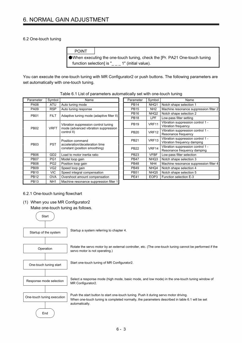
6. NORMAL GAIN ADJUSTMENT
6 - 3
6.2 One-touch tuning
POINT
When executing the one-touch tuning, check the [Pr. PA21 One-touch tuning
function selection] is "_ _ _ 1" (initial value).
You can execute the one-touch tuning with MR Configurator2 or push buttons. The following parameters are
set automatically with one-touch tuning.
Table 6.1 List of parameters automatically set with one-touch tuning
Parameter Symbol Name Parameter Symbol Name
PA08 ATU Auto tuning mode PB14 NHQ1 Notch shape selection 1 PA09 RSP Auto tuning response PB15 NH2 Machine resonance suppression filter 2
PB01 FILT Adaptive tuning mode (adaptive filter II) PB16 NHQ2 Notch shape selection 2 PB18 LPF Low-pass filter setting
PB02 VRFT Vibration suppression control tuning mode (advanced vibration suppression control II)
PB19 VRF11
Vibration suppression control 1 - Vibration frequency
PB20 VRF12
Vibration suppression control 1 - Resonance frequency
PB03 PST Position command acceleration/deceleration time constant (position smoothing)
PB21 VRF13
Vibration suppression control 1 - Vibration frequency damping
PB22 VRF14
Vibration suppression control 1 - Resonance frequency damping
PB06 GD2 Load to motor inertia ratio PB23 VFBF Low-pass filter selection PB07 PG1 Model loop gain PB47 NHQ3 Notch shape selection 3 PB08 PG2 Position loop gain PB48 NH4 Machine resonance suppression filter 4PB09 VG2 Speed loop gain PB49 NHQ4 Notch shape selection 4 PB10 VIC Speed integral compensation PB51 NHQ5 Notch shape selection 5 PB12 OVA Overshoot amount compensation PE41 EOP3 Function selection E-3
PB13 NH1 Machine resonance suppression filter 1
6.2.1 One-touch tuning flowchart
(1) When you use MR Configurator2
Make one-touch tuning as follows.
Start
Startup of the system
Operation
One-touch tuning start
Response mode selection
One-touch tuning execution
End
Startup a system referring to chapter 4.
Rotate the servo motor by an external controller, etc. (The one-touch tuning cannot be performed if the servo motor is not operating.)
Start one-touch tuning of MR Configurator2.
Select a response mode (high mode, basic mode, and low mode) in the one-touch tuning window of MR Configurator2.
Push the start button to start one-touch tuning. Push it during servo motor driving. When one-touch tuning is completed normally, the parameters described in table 6.1 will be set automatically.
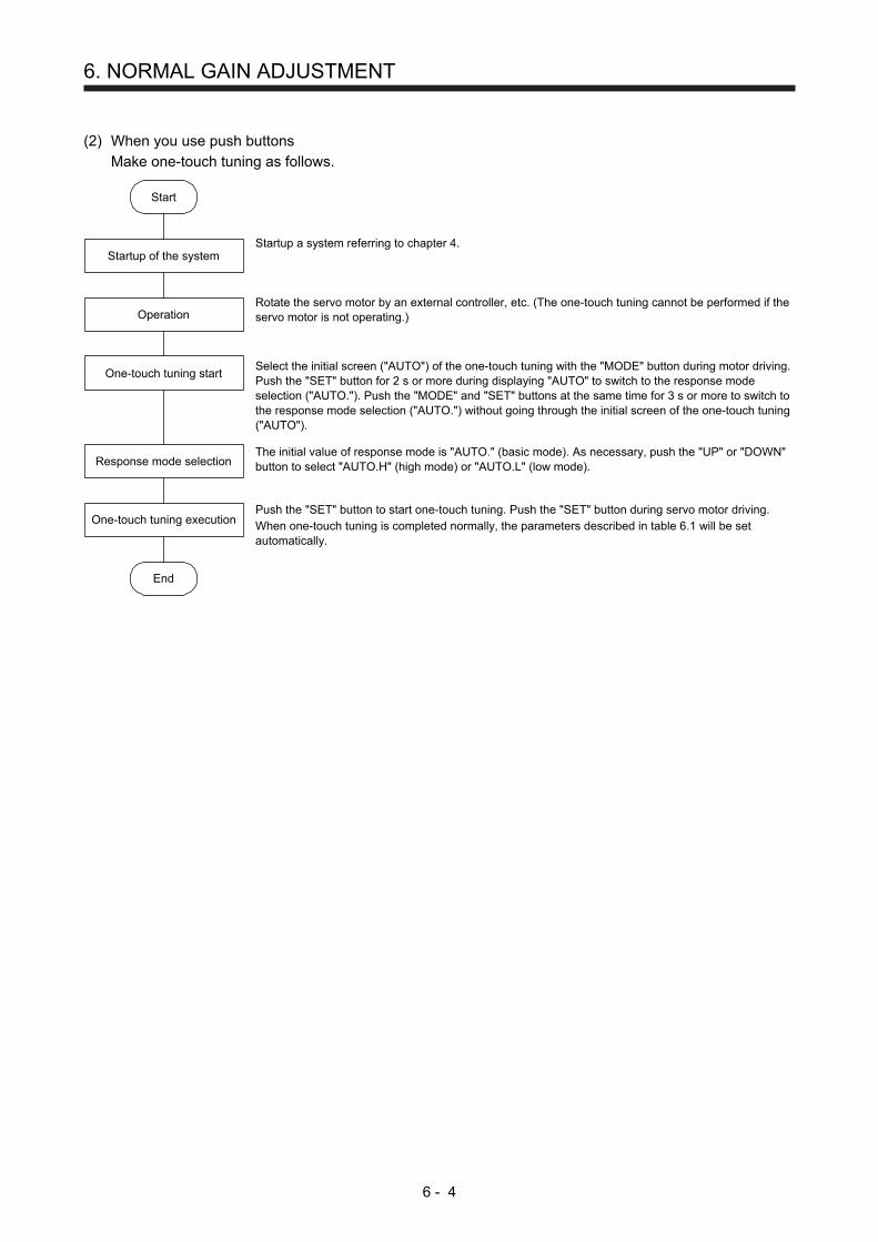
6. NORMAL GAIN ADJUSTMENT
6 - 4
(2) When you use push buttons
Make one-touch tuning as follows.
Start
Startup of the system
Operation
One-touch tuning start
Response mode selection
One-touch tuning execution
End
Startup a system referring to chapter 4.
Rotate the servo motor by an external controller, etc. (The one-touch tuning cannot be performed if the servo motor is not operating.) Select the initial screen ("AUTO") of the one-touch tuning with the "MODE" button during motor driving. Push the "SET" button for 2 s or more during displaying "AUTO" to switch to the response mode selection ("AUTO."). Push the "MODE" and "SET" buttons at the same time for 3 s or more to switch to the response mode selection ("AUTO.") without going through the initial screen of the one-touch tuning ("AUTO").
The initial value of response mode is "AUTO." (basic mode). As necessary, push the "UP" or "DOWN" button to select "AUTO.H" (high mode) or "AUTO.L" (low mode).
Push the "SET" button to start one-touch tuning. Push the "SET" button during servo motor driving. When one-touch tuning is completed normally, the parameters described in table 6.1 will be set automatically.

6. NORMAL GAIN ADJUSTMENT
6 - 5
6.2.2 Display transition and operation procedure of one-touch tuning
(1) When you use MR Configurator2
(a) Response mode selection
Select a response mode from three modes in the one-touch tuning window of MR Configurator2.
Response mode Explanation
High mode This mode is for high rigid system.
Basic mode This mode is for standard system.
Low mode This mode is for low rigid system.
Refer to the following table for selecting a response mode.
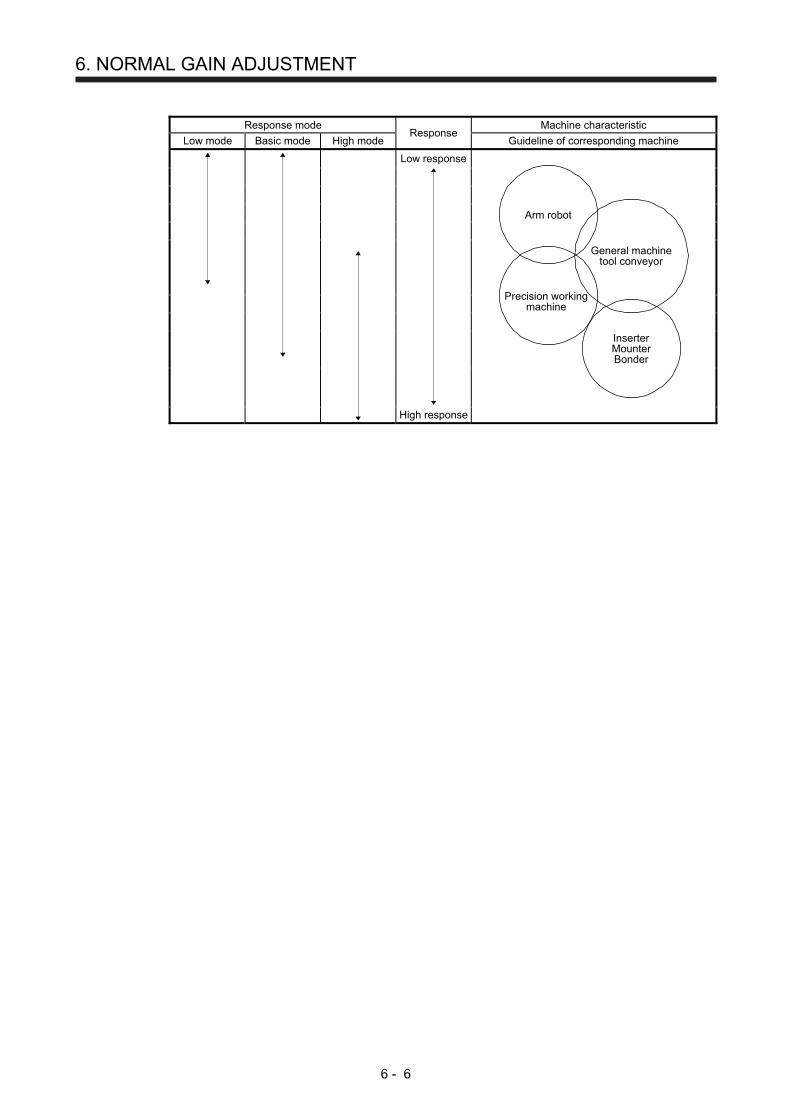
6. NORMAL GAIN ADJUSTMENT
6 - 6
Response mode
Response Machine characteristic
Low mode Basic mode High mode Guideline of corresponding machine
Low response
General machinetool conveyor
Arm robot
Precision workingmachine
InserterMounterBonder
High response
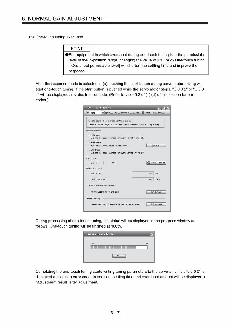
6. NORMAL GAIN ADJUSTMENT
6 - 7
(b) One-touch tuning execution
POINT
For equipment in which overshoot during one-touch tuning is in the permissible
level of the in-position range, changing the value of [Pr. PA25 One-touch tuning
- Overshoot permissible level] will shorten the settling time and improve the
response.
After the response mode is selected in (a), pushing the start button during servo motor driving will
start one-touch tuning. If the start button is pushed while the servo motor stops, "C 0 0 2" or "C 0 0
4" will be displayed at status in error code. (Refer to table 6.2 of (1) (d) of this section for error
codes.)
During processing of one-touch tuning, the status will be displayed in the progress window as
follows. One-touch tuning will be finished at 100%.
Completing the one-touch tuning starts writing tuning parameters to the servo amplifier. "0 0 0 0" is
displayed at status in error code. In addition, settling time and overshoot amount will be displayed in
"Adjustment result" after adjustment.
6. NORMAL GAIN ADJUSTMENT
6 - 8
(c) Stop of one-touch tuning
During one-touch tuning, pushing the stop button stops one-touch tuning.
If the one-touch tuning is stopped, "C 0 0 0" will be displayed at status in error code.
(d) Error occurrence
If a tuning error occurs during tuning, one-touch tuning will be forcibly terminated. With that, the
following error code will be displayed in status. Check the cause of tuning error.
Table 6.2 Error code list during one-touch tuning
Error code Name Description Action
C000 Tuning canceled The stop button or "SET" of the push button was pushed.
C001 Overshoot exceeded The overshoot amount is lager than the value set in [Pr. PA10 In-position range].
Increase the in-position range.
C002 Servo-off during tuning The one-touch tuning was attempted during servo-off.
Perform the one-touch tuning after servo-on.
C003 Control mode error The one-touch tuning was attempted while the torque control mode was selected in the control modes.
Select the position control mode or speed control mode for the control mode from the controller, and then make one-touch tuning.
C004 Time-out 1. One cycle time during the operation has been over 30 s.
Set the one cycle time during the operation to 30 s or less.
2. The command speed is low. Set the servo motor speed to100 r/min or higher.
3. The operation interval of the continuous operation is short.
Maintain the operation interval during motor driving about 200 ms.
C005 Load to motor inertia ratio misestimated
1. The estimation of the load to motor inertia ratio at one-touch tuning was a failure.
Drive the motor with meeting conditions as follows.
Time to reach 2000 r/min is the acceleration/deceleration time constant of 5 s or less. Speed is 150 r/min or higher. The load to motor inertia ratio is 100 times or less. The acceleration/deceleration torque is 10% or more of the rated torque.
2. The load to motor inertia ratio was not estimated due to such as an oscillation.
Set to the auto tuning mode that does not estimate the load to motor inertia ratio as follows, and then execute the one-touch tuning.
Select "Auto tuning mode 2 (_ _ _ 2)", "Manual mode (_ _ _ 3)", or "2 gain adjustment mode 2 (_ _ _ 4)" of "Gain adjustment mode selection" in [Pr. PA08]. Set [Pr. PB06 Load to motor inertia ratio] properly with manual setting.
C00F One-touch tuning disabled
"One-touch tuning function selection" in [Pr. PA21] is "Disabled (_ _ _ 0)".
Select "Enabled (_ _ _ 1)".
(e) If an alarm occurs
If an alarm occurs during tuning, one-touch tuning will be forcibly terminated.
Remove the cause of the alarm and execute one-touch tuning again.
(f) If a warning occurs
If a warning which continue the motor driving occurs during the tuning, one-touch tuning will be
continued.
If a warning which does not continue the motor driving occurs during the tuning, one-touch tuning will
be stopped.
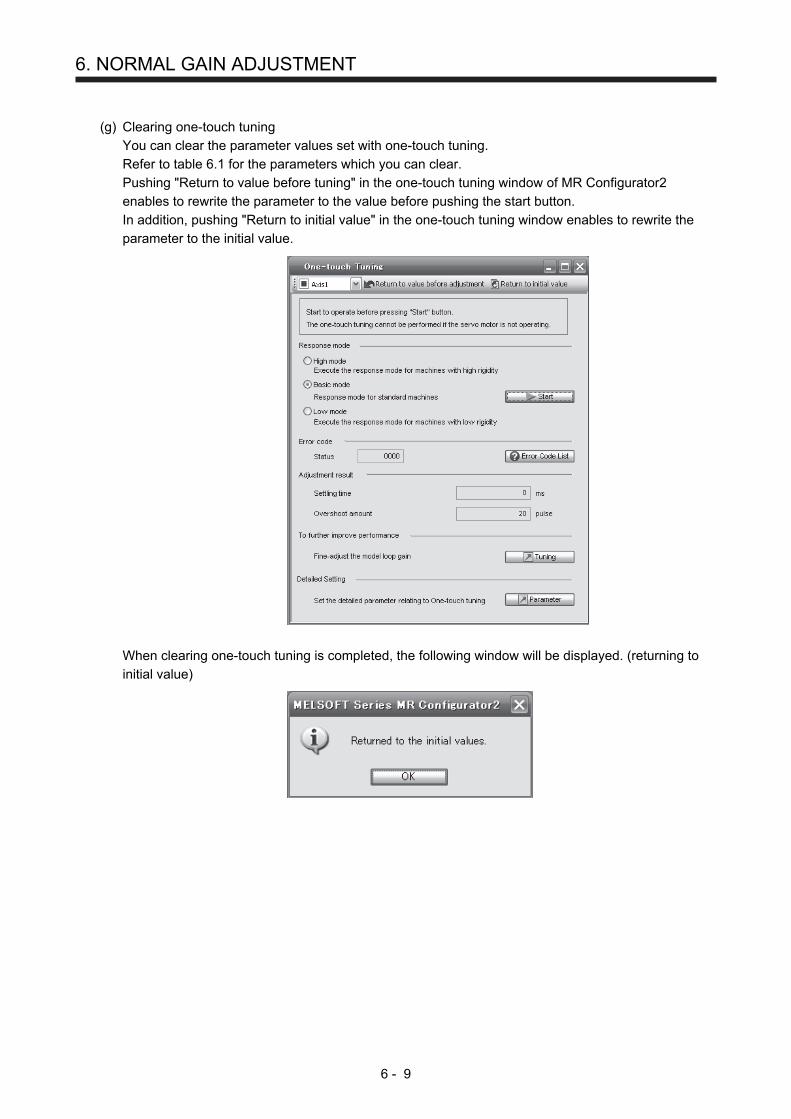
6. NORMAL GAIN ADJUSTMENT
6 - 9
(g) Clearing one-touch tuning
You can clear the parameter values set with one-touch tuning.
Refer to table 6.1 for the parameters which you can clear.
Pushing "Return to value before tuning" in the one-touch tuning window of MR Configurator2
enables to rewrite the parameter to the value before pushing the start button.
In addition, pushing "Return to initial value" in the one-touch tuning window enables to rewrite the
parameter to the initial value.
When clearing one-touch tuning is completed, the following window will be displayed. (returning to
initial value)

6. NORMAL GAIN ADJUSTMENT
6 - 10
(2) When you use push buttons
POINT
Push the "MODE" and "SET" buttons at the same time for 3 s or more to switch
to the response mode selection ("AUTO.") without going through the initial
screen of the one-touch tuning ("AUTO").
(a) Response mode selection
Select a response mode of the one-touch tuning from 3 modes with "UP" or "DOWN". Refer to (1) (a)
of this section for a guideline of response mode.
Response mode selection display
Low mode: This mode is for low rigid system.
Basic mode: This mode is for standard system.
High mode: This mode is for high rigid system.
DOWNUP

6. NORMAL GAIN ADJUSTMENT
6 - 11
(b) One-touch tuning execution
POINT
For equipment in which overshoot during one-touch tuning is in the permissible
level of the in-position range, changing the value of [Pr. PA25 One-touch tuning
- Overshoot permissible level] will shorten the settling time and improve the
response.
After the response mode is selected in (a), pushing the "SET" button will start one-touch tuning.
Completing the one-touch tuning will start writing the auto-tuned parameters to the servoamplifier.
The one-touch tuning progress is displayed with 0% to 100%.The decimal point moves left to right in rotation during the tuning.To switch the display to the status display during the tuning, push the "MODE" button.
One-touch tuning inprogress
Complete
(c) Stop of one-touch tuning
The stop symbol and error code "C 000" (cancel during tuning) will be displayed by turnswith 2 s interval.
2 s interval
Error code
The one-touch tuning mode can be stopped by pushing the "SET" button regardless ofdisplayed item.
Stop symbol
Initial screen
Pushing the "SET" button will switch to the initial screen.
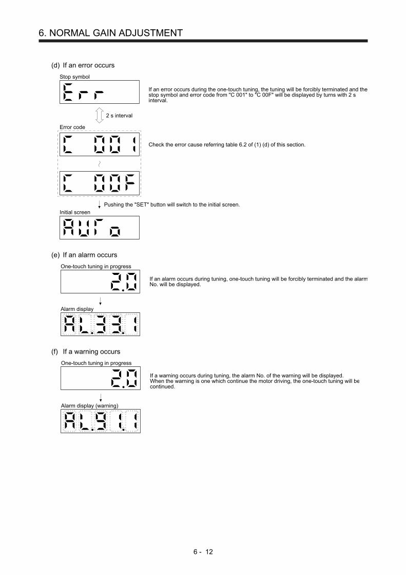
6. NORMAL GAIN ADJUSTMENT
6 - 12
(d) If an error occurs
Check the error cause referring table 6.2 of (1) (d) of this section.
2 s interval
Error code
If an error occurs during the one-touch tuning, the tuning will be forcibly terminated and thestop symbol and error code from "C 001" to "C 00F" will be displayed by turns with 2 sinterval.
Stop symbol
Initial screen
Pushing the "SET" button will switch to the initial screen.
(e) If an alarm occurs
If an alarm occurs during tuning, one-touch tuning will be forcibly terminated and the alarmNo. will be displayed.
One-touch tuning in progress
Alarm display
(f) If a warning occurs
If a warning occurs during tuning, the alarm No. of the warning will be displayed.When the warning is one which continue the motor driving, the one-touch tuning will becontinued.
One-touch tuning in progress
Alarm display (warning)
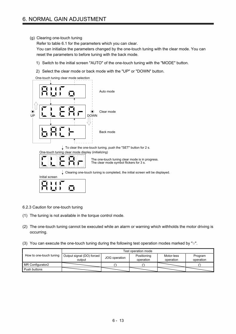
6. NORMAL GAIN ADJUSTMENT
6 - 13
(g) Clearing one-touch tuning
Refer to table 6.1 for the parameters which you can clear.
You can initialize the parameters changed by the one-touch tuning with the clear mode. You can
reset the parameters to before tuning with the back mode.
1) Switch to the initial screen "AUTO" of the one-touch tuning with the "MODE" button.
2) Select the clear mode or back mode with the "UP" or "DOWN" button.
One-touch tuning clear mode selection
DOWNUP
To clear the one-touch tuning, push the "SET" button for 2 s.
The one-touch tuning clear mode is in progress.The clear mode symbol flickers for 3 s.
Clearing one-touch tuning is completed, the initial screen will be displayed.
One-touch tuning clear mode display (initializing)
Initial screen
Auto mode
Clear mode
Back mode
6.2.3 Caution for one-touch tuning
(1) The tuning is not available in the torque control mode.
(2) The one-touch tuning cannot be executed while an alarm or warning which withholds the motor driving is
occurring.
(3) You can execute the one-touch tuning during the following test operation modes marked by "".
How to one-touch tuning Test operation mode
Output signal (DO) forced output
JOG operation Positioning operation
Motor-less operation
Program operation
MR Configurator2 Push buttons

6. NORMAL GAIN ADJUSTMENT
6 - 14
6.3 Auto tuning
6.3.1 Auto tuning mode
The servo amplifier has a real-time auto tuning function which estimates the machine characteristic (load to
motor inertia ratio) in real time and automatically sets the optimum gains according to that value. This
function permits ease of gain adjustment of the servo amplifier.
(1) Auto tuning mode 1
The servo amplifier is factory-set to the auto tuning mode 1.
In this mode, the load to motor inertia ratio of a machine is always estimated to set the optimum gains
automatically.
The following parameters are automatically adjusted in the auto tuning mode 1.
Parameter Symbol Name
PB06 GD2 Load to motor inertia ratio
PB07 PG1 Model loop gain
PB08 PG2 Position loop gain
PB09 VG2 Speed loop gain
PB10 VIC Speed integral compensation
POINT
The auto tuning mode 1 may not be performed properly if all of the following
conditions are not satisfied.
Time to reach 2000 r/min is the acceleration/deceleration time constant of 5 s
or less.
Speed is 150 r/min or higher.
The load to motor inertia ratio is 100 times or less.
The acceleration/deceleration torque is 10% or more of the rated torque.
Under operating conditions which will impose sudden disturbance torque during
acceleration/deceleration or on a machine which is extremely loose, auto tuning
may not function properly, either. In such cases, use the auto tuning mode 2 or
manual mode to make gain adjustment.
(2) Auto tuning mode 2
Use the auto tuning mode 2 when proper gain adjustment cannot be made by auto tuning mode 1. Since
the load to motor inertia ratio is not estimated in this mode, set the value of a correct load to motor
inertia ratio in [Pr. PB06].
The following parameters are automatically adjusted in the auto tuning mode 2.
Parameter Symbol Name
PB07 PG1 Model loop gain
PB08 PG2 Position loop gain
PB09 VG2 Speed loop gain
PB10 VIC Speed integral compensation
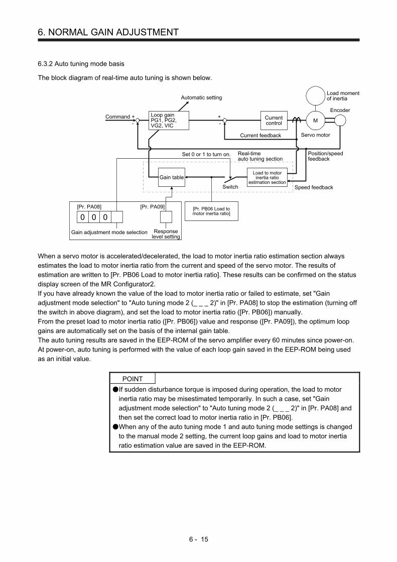
6. NORMAL GAIN ADJUSTMENT
6 - 15
6.3.2 Auto tuning mode basis
The block diagram of real-time auto tuning is shown below.
Loop gainPG1, PG2,VG2, VIC
Currentcontrol
Load to motorinertia ratio
estimation sectionGain table
[Pr. PB06 Load tomotor inertia ratio]
Responselevel setting
Gain adjustment mode selection
[Pr. PA08]
+-
+-
Real-timeauto tuning section
Set 0 or 1 to turn on.
Switch
Current feedback
Position/speedfeedback
Speed feedback
Load momentof inertia
EncoderCommand
Automatic setting
[Pr. PA09]
M
Servo motor
0 0 0
When a servo motor is accelerated/decelerated, the load to motor inertia ratio estimation section always
estimates the load to motor inertia ratio from the current and speed of the servo motor. The results of
estimation are written to [Pr. PB06 Load to motor inertia ratio]. These results can be confirmed on the status
display screen of the MR Configurator2.
If you have already known the value of the load to motor inertia ratio or failed to estimate, set "Gain
adjustment mode selection" to "Auto tuning mode 2 (_ _ _ 2)" in [Pr. PA08] to stop the estimation (turning off
the switch in above diagram), and set the load to motor inertia ratio ([Pr. PB06]) manually.
From the preset load to motor inertia ratio ([Pr. PB06]) value and response ([Pr. PA09]), the optimum loop
gains are automatically set on the basis of the internal gain table.
The auto tuning results are saved in the EEP-ROM of the servo amplifier every 60 minutes since power-on.
At power-on, auto tuning is performed with the value of each loop gain saved in the EEP-ROM being used
as an initial value.
POINT
If sudden disturbance torque is imposed during operation, the load to motor
inertia ratio may be misestimated temporarily. In such a case, set "Gain
adjustment mode selection" to "Auto tuning mode 2 (_ _ _ 2)" in [Pr. PA08] and
then set the correct load to motor inertia ratio in [Pr. PB06].
When any of the auto tuning mode 1 and auto tuning mode settings is changed
to the manual mode 2 setting, the current loop gains and load to motor inertia
ratio estimation value are saved in the EEP-ROM.

6. NORMAL GAIN ADJUSTMENT
6 - 16
6.3.3 Adjustment procedure by auto tuning
Since auto tuning is enabled before shipment from the factory, simply running the servo motor automatically
sets the optimum gains that match the machine. Merely changing the response level setting value as
required completes the adjustment. The adjustment procedure is as follows.
Auto tuning adjustment
Acceleration/deceleration repeated
Auto tuning conditionsare not satisfied? (Estimation of
load to motor inertia ratio is difficult.)
Load to motor inertia ratioestimation value stable?
Set [Pr. PA08] to "_ _ _ 2" and set[Pr. PB06 Load to motor inertia ratio]manually.
Adjust response level setting sothat desired response is achievedon vibration-free level.
To 2 gain adjustmentmode 2
Requested performancesatisfied?
End
Yes
No
Yes
No
No
Yes
Acceleration/deceleration repeated
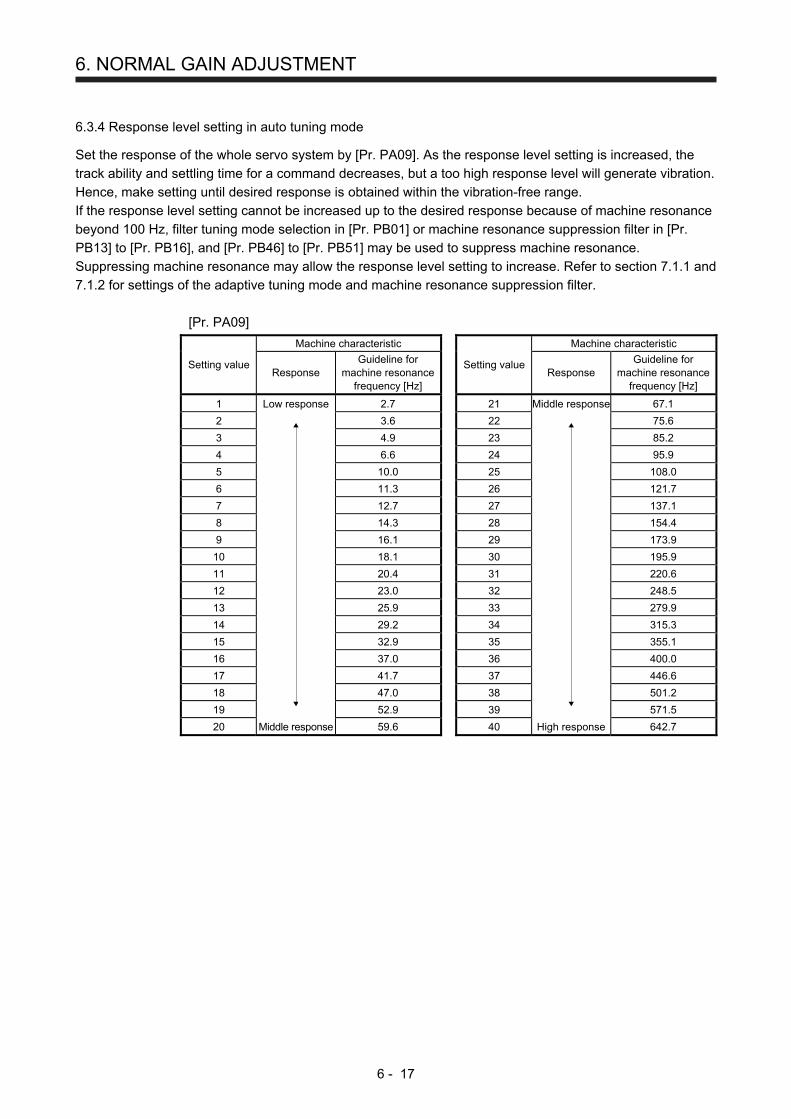
6. NORMAL GAIN ADJUSTMENT
6 - 17
6.3.4 Response level setting in auto tuning mode
Set the response of the whole servo system by [Pr. PA09]. As the response level setting is increased, the
track ability and settling time for a command decreases, but a too high response level will generate vibration.
Hence, make setting until desired response is obtained within the vibration-free range.
If the response level setting cannot be increased up to the desired response because of machine resonance
beyond 100 Hz, filter tuning mode selection in [Pr. PB01] or machine resonance suppression filter in [Pr.
PB13] to [Pr. PB16], and [Pr. PB46] to [Pr. PB51] may be used to suppress machine resonance.
Suppressing machine resonance may allow the response level setting to increase. Refer to section 7.1.1 and
7.1.2 for settings of the adaptive tuning mode and machine resonance suppression filter.
[Pr. PA09]
Setting value
Machine characteristic
Setting value
Machine characteristic
Response Guideline for
machine resonance frequency [Hz]
Response
Guideline for machine resonance
frequency [Hz]
1 Low response 2.7 21 Middle response 67.1
2
3.6 22
75.6
3 4.9 23 85.2
4 6.6 24 95.9
5 10.0 25 108.0
6 11.3 26 121.7
7 12.7 27 137.1
8 14.3 28 154.4
9 16.1 29 173.9
10 18.1 30 195.9
11 20.4 31 220.6
12 23.0 32 248.5
13 25.9 33 279.9
14 29.2 34 315.3
15 32.9 35 355.1
16 37.0 36 400.0
17 41.7 37 446.6
18 47.0 38 501.2
19 52.9 39 571.5
20 Middle response 59.6 40 High response 642.7
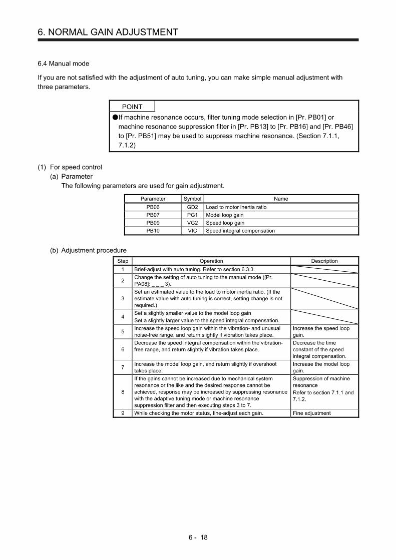
6. NORMAL GAIN ADJUSTMENT
6 - 18
6.4 Manual mode
If you are not satisfied with the adjustment of auto tuning, you can make simple manual adjustment with
three parameters.
POINT
If machine resonance occurs, filter tuning mode selection in [Pr. PB01] or
machine resonance suppression filter in [Pr. PB13] to [Pr. PB16] and [Pr. PB46]
to [Pr. PB51] may be used to suppress machine resonance. (Section 7.1.1,
7.1.2)
(1) For speed control
(a) Parameter
The following parameters are used for gain adjustment.
Parameter Symbol Name
PB06 GD2 Load to motor inertia ratio
PB07 PG1 Model loop gain
PB09 VG2 Speed loop gain
PB10 VIC Speed integral compensation
(b) Adjustment procedure
Step Operation Description
1 Brief-adjust with auto tuning. Refer to section 6.3.3.
2 Change the setting of auto tuning to the manual mode ([Pr. PA08]: _ _ _ 3).
3 Set an estimated value to the load to motor inertia ratio. (If the estimate value with auto tuning is correct, setting change is not required.)
4 Set a slightly smaller value to the model loop gain Set a slightly larger value to the speed integral compensation.
5 Increase the speed loop gain within the vibration- and unusual noise-free range, and return slightly if vibration takes place.
Increase the speed loop gain.
6 Decrease the speed integral compensation within the vibration-free range, and return slightly if vibration takes place.
Decrease the time constant of the speed integral compensation.
7 Increase the model loop gain, and return slightly if overshoot takes place.
Increase the model loop gain.
8
If the gains cannot be increased due to mechanical system resonance or the like and the desired response cannot be achieved, response may be increased by suppressing resonance with the adaptive tuning mode or machine resonance suppression filter and then executing steps 3 to 7.
Suppression of machine resonance Refer to section 7.1.1 and 7.1.2.
9 While checking the motor status, fine-adjust each gain. Fine adjustment
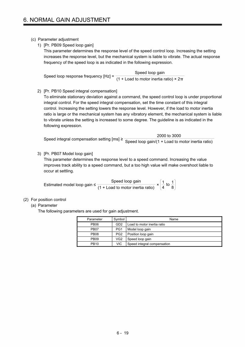
6. NORMAL GAIN ADJUSTMENT
6 - 19
(c) Parameter adjustment
1) [Pr. PB09 Speed loop gain]
This parameter determines the response level of the speed control loop. Increasing the setting
increases the response level, but the mechanical system is liable to vibrate. The actual response
frequency of the speed loop is as indicated in the following expression.
Speed loop response frequency [Hz] = (1 + Load to motor inertia ratio) × 2
Speed loop gain
2) [Pr. PB10 Speed integral compensation]
To eliminate stationary deviation against a command, the speed control loop is under proportional
integral control. For the speed integral compensation, set the time constant of this integral
control. Increasing the setting lowers the response level. However, if the load to motor inertia
ratio is large or the mechanical system has any vibratory element, the mechanical system is liable
to vibrate unless the setting is increased to some degree. The guideline is as indicated in the
following expression.
Speed integral compensation setting [ms] ≥ 2000 to 3000
Speed loop gain/(1 + Load to motor inertia ratio)
3) [Pr. PB07 Model loop gain]
This parameter determines the response level to a speed command. Increasing the value
improves track ability to a speed command, but a too high value will make overshoot liable to
occur at settling.
Estimated model loop gain ≤ (1 + Load to motor inertia ratio)
Speed loop gain ×
81
41 to
(2) For position control
(a) Parameter
The following parameters are used for gain adjustment.
Parameter Symbol Name
PB06 GD2 Load to motor inertia ratio
PB07 PG1 Model loop gain
PB08 PG2 Position loop gain
PB09 VG2 Speed loop gain
PB10 VIC Speed integral compensation
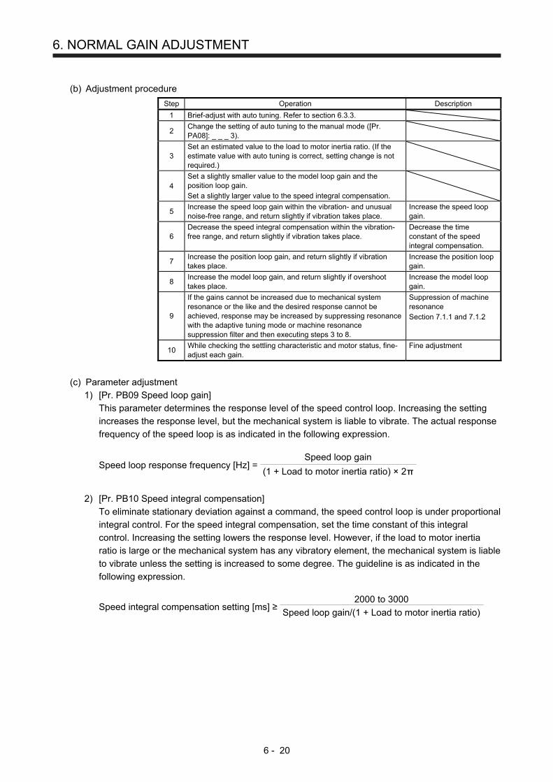
6. NORMAL GAIN ADJUSTMENT
6 - 20
(b) Adjustment procedure
Step Operation Description
1 Brief-adjust with auto tuning. Refer to section 6.3.3.
2 Change the setting of auto tuning to the manual mode ([Pr. PA08]: _ _ _ 3).
3 Set an estimated value to the load to motor inertia ratio. (If the estimate value with auto tuning is correct, setting change is not required.)
4 Set a slightly smaller value to the model loop gain and the position loop gain. Set a slightly larger value to the speed integral compensation.
5 Increase the speed loop gain within the vibration- and unusual noise-free range, and return slightly if vibration takes place.
Increase the speed loop gain.
6 Decrease the speed integral compensation within the vibration-free range, and return slightly if vibration takes place.
Decrease the time constant of the speed integral compensation.
7 Increase the position loop gain, and return slightly if vibration takes place.
Increase the position loop gain.
8 Increase the model loop gain, and return slightly if overshoot takes place.
Increase the model loop gain.
9
If the gains cannot be increased due to mechanical system resonance or the like and the desired response cannot be achieved, response may be increased by suppressing resonance with the adaptive tuning mode or machine resonance suppression filter and then executing steps 3 to 8.
Suppression of machine resonance Section 7.1.1 and 7.1.2
10 While checking the settling characteristic and motor status, fine-adjust each gain.
Fine adjustment
(c) Parameter adjustment
1) [Pr. PB09 Speed loop gain]
This parameter determines the response level of the speed control loop. Increasing the setting
increases the response level, but the mechanical system is liable to vibrate. The actual response
frequency of the speed loop is as indicated in the following expression.
Speed loop response frequency [Hz] = (1 + Load to motor inertia ratio) × 2
Speed loop gain
2) [Pr. PB10 Speed integral compensation]
To eliminate stationary deviation against a command, the speed control loop is under proportional
integral control. For the speed integral compensation, set the time constant of this integral
control. Increasing the setting lowers the response level. However, if the load to motor inertia
ratio is large or the mechanical system has any vibratory element, the mechanical system is liable
to vibrate unless the setting is increased to some degree. The guideline is as indicated in the
following expression.
Speed integral compensation setting [ms] ≥ 2000 to 3000
Speed loop gain/(1 + Load to motor inertia ratio)
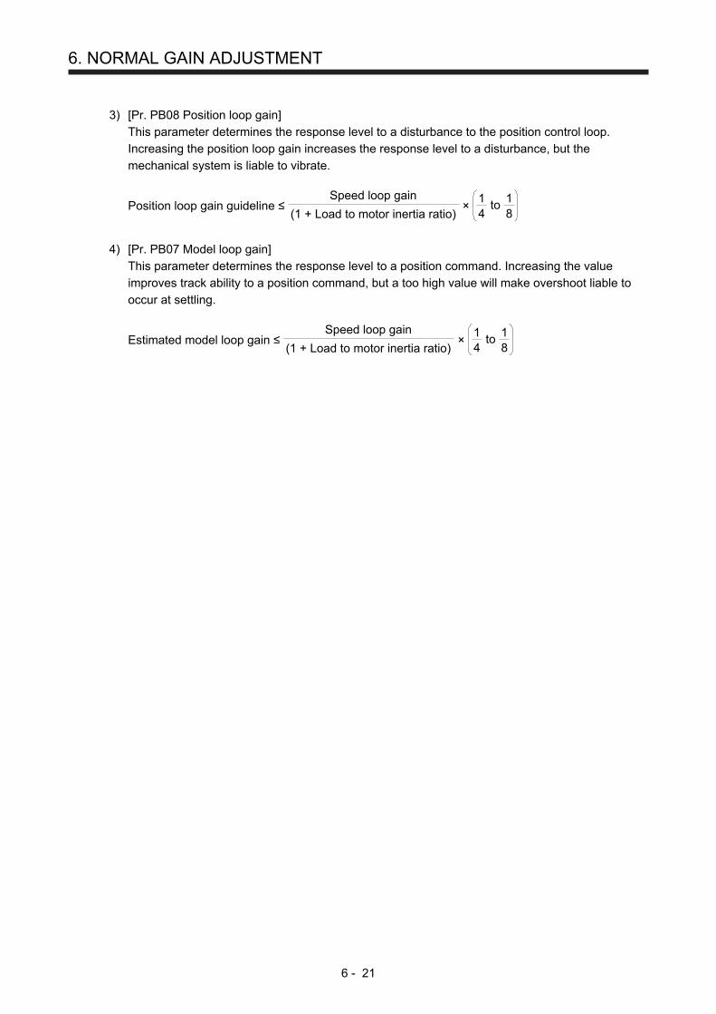
6. NORMAL GAIN ADJUSTMENT
6 - 21
3) [Pr. PB08 Position loop gain]
This parameter determines the response level to a disturbance to the position control loop.
Increasing the position loop gain increases the response level to a disturbance, but the
mechanical system is liable to vibrate.
Position loop gain guideline ≤ (1 + Load to motor inertia ratio)
Speed loop gain ×
81
41 to
4) [Pr. PB07 Model loop gain]
This parameter determines the response level to a position command. Increasing the value
improves track ability to a position command, but a too high value will make overshoot liable to
occur at settling.
Estimated model loop gain ≤ (1 + Load to motor inertia ratio)
Speed loop gain ×
81
41 to
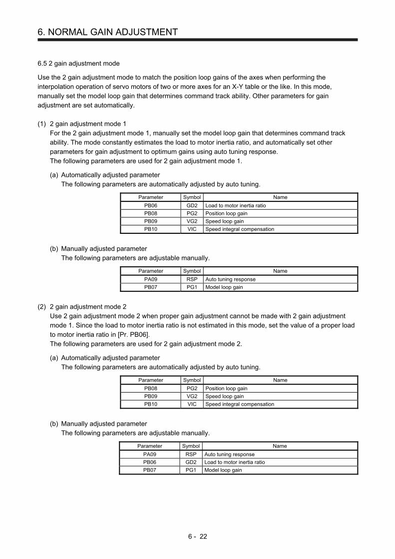
6. NORMAL GAIN ADJUSTMENT
6 - 22
6.5 2 gain adjustment mode
Use the 2 gain adjustment mode to match the position loop gains of the axes when performing the
interpolation operation of servo motors of two or more axes for an X-Y table or the like. In this mode,
manually set the model loop gain that determines command track ability. Other parameters for gain
adjustment are set automatically.
(1) 2 gain adjustment mode 1
For the 2 gain adjustment mode 1, manually set the model loop gain that determines command track
ability. The mode constantly estimates the load to motor inertia ratio, and automatically set other
parameters for gain adjustment to optimum gains using auto tuning response.
The following parameters are used for 2 gain adjustment mode 1.
(a) Automatically adjusted parameter
The following parameters are automatically adjusted by auto tuning.
Parameter Symbol Name
PB06 GD2 Load to motor inertia ratio
PB08 PG2 Position loop gain
PB09 VG2 Speed loop gain
PB10 VIC Speed integral compensation
(b) Manually adjusted parameter
The following parameters are adjustable manually.
Parameter Symbol Name
PA09 RSP Auto tuning response
PB07 PG1 Model loop gain
(2) 2 gain adjustment mode 2
Use 2 gain adjustment mode 2 when proper gain adjustment cannot be made with 2 gain adjustment
mode 1. Since the load to motor inertia ratio is not estimated in this mode, set the value of a proper load
to motor inertia ratio in [Pr. PB06].
The following parameters are used for 2 gain adjustment mode 2.
(a) Automatically adjusted parameter
The following parameters are automatically adjusted by auto tuning.
Parameter Symbol Name
PB08 PG2 Position loop gain
PB09 VG2 Speed loop gain
PB10 VIC Speed integral compensation
(b) Manually adjusted parameter
The following parameters are adjustable manually.
Parameter Symbol Name
PA09 RSP Auto tuning response
PB06 GD2 Load to motor inertia ratio
PB07 PG1 Model loop gain

6. NORMAL GAIN ADJUSTMENT
6 - 23
(3) Adjustment procedure of 2 gain adjustment mode
POINT
Set the same value in [Pr. PB07 Model loop gain] for the axis used in 2 gain
adjustment mode.
Step Operation Description
1 Set to the auto tuning mode. Select the auto tuning
mode 1.
2 During operation, increase the response level setting value in [Pr. PA09], and return the setting if vibration occurs.
Adjustment in auto tuning mode 1
3 Check value of the model loop gain and the load to motor inertia ratio in advance.
Check the upper setting limits.
4 Set the 2 gain adjustment mode 1 ([Pr. PA08]: _ _ _ 0). Select the 2 gain
adjustment mode 1 (interpolation mode).
5 When the load to motor inertia ratio is different from the design value, select the 2 gain adjustment mode 2 ([Pr. PA08]: _ _ _ 4) and then set the load to motor inertia ratio manually in [Pr. PB06].
Check the load to motor inertia ratio.
6 Set the model loop gain of all the axes to be interpolated to the same value. At that time, adjust to the setting value of the axis, which has the smallest model loop gain.
Set position loop gain.
7 Considering the interpolation characteristic and motor status, fine-adjust the model loop gain and response level setting.
Fine adjustment
(4) Parameter adjustment
[Pr. PB07 Model loop gain]
This parameter determines the response level of the position control loop. Increasing the value improves
track ability to a position command, but a too high value will make overshoot liable to occur at settling.
The droop pulse value is determined by the following expression.
Number of droop pulses [pulse] = Model loop gain setting
Position command frequency [pulse/s]
Position command frequency = Speed [r/min]
60 × Encoder resolution (number of pulses per servo motor
revolution)

6. NORMAL GAIN ADJUSTMENT
6 - 24
MEMO
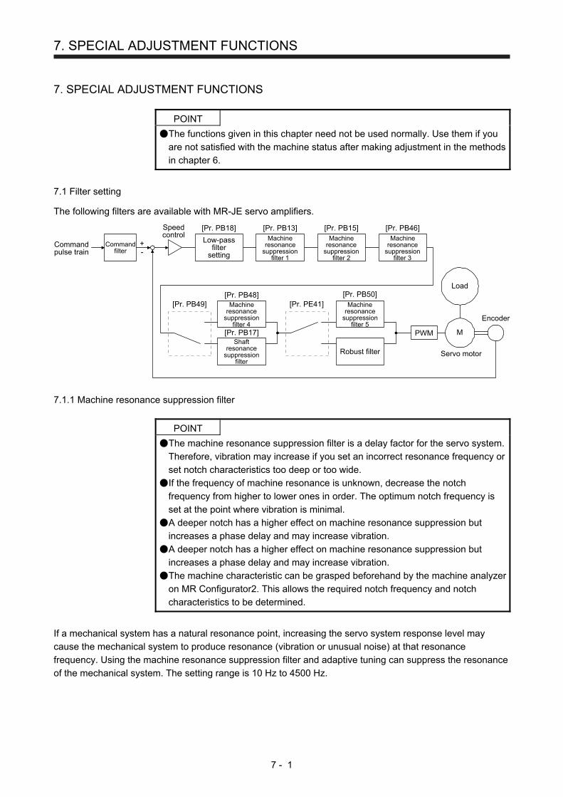
7. SPECIAL ADJUSTMENT FUNCTIONS
7 - 1
7. SPECIAL ADJUSTMENT FUNCTIONS
POINT
The functions given in this chapter need not be used normally. Use them if you
are not satisfied with the machine status after making adjustment in the methods
in chapter 6.
7.1 Filter setting
The following filters are available with MR-JE servo amplifiers.
Commandpulse train
Commandfilter
Low-passfilter
setting
Encoder
Servo motor
PWM M
Load
[Pr. PB18]
+-
Machineresonance
suppressionfilter 1
[Pr. PB13] [Pr. PB15] [Pr. PB46]Machine
resonancesuppression
filter 2
Machineresonance
suppressionfilter 3
Machineresonance
suppressionfilter 4
Machineresonance
suppressionfilter 5
Shaftresonance
suppressionfilter
Robust filter
[Pr. PB48] [Pr. PB50]
[Pr. PB17]
Speedcontrol
[Pr. PB49] [Pr. PE41]
7.1.1 Machine resonance suppression filter
POINT
The machine resonance suppression filter is a delay factor for the servo system.
Therefore, vibration may increase if you set an incorrect resonance frequency or
set notch characteristics too deep or too wide.
If the frequency of machine resonance is unknown, decrease the notch
frequency from higher to lower ones in order. The optimum notch frequency is
set at the point where vibration is minimal.
A deeper notch has a higher effect on machine resonance suppression but
increases a phase delay and may increase vibration.
A deeper notch has a higher effect on machine resonance suppression but
increases a phase delay and may increase vibration.
The machine characteristic can be grasped beforehand by the machine analyzer
on MR Configurator2. This allows the required notch frequency and notch
characteristics to be determined.
If a mechanical system has a natural resonance point, increasing the servo system response level may
cause the mechanical system to produce resonance (vibration or unusual noise) at that resonance
frequency. Using the machine resonance suppression filter and adaptive tuning can suppress the resonance
of the mechanical system. The setting range is 10 Hz to 4500 Hz.
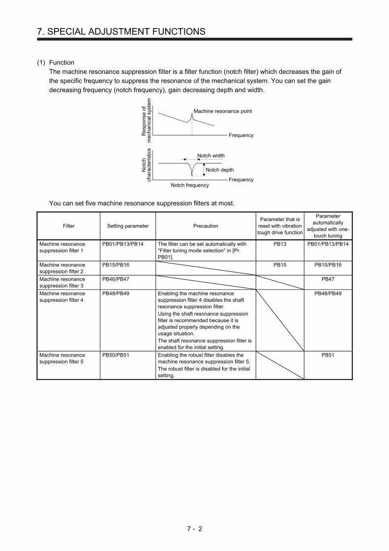
7. SPECIAL ADJUSTMENT FUNCTIONS
7 - 2
(1) Function
The machine resonance suppression filter is a filter function (notch filter) which decreases the gain of
the specific frequency to suppress the resonance of the mechanical system. You can set the gain
decreasing frequency (notch frequency), gain decreasing depth and width.
Re
spo
nse
of
mec
hani
cal s
yste
mN
otch
char
acte
ristic
s
Machine resonance point
Notch frequencyFrequency
Frequency
Notch width
Notch depth
You can set five machine resonance suppression filters at most.
Filter Setting parameter Precaution Parameter that is
reset with vibration tough drive function
Parameter automatically
adjusted with one-touch tuning
Machine resonance suppression filter 1
PB01/PB13/PB14 The filter can be set automatically with "Filter tuning mode selection" in [Pr. PB01].
PB13 PB01/PB13/PB14
Machine resonance suppression filter 2
PB15/PB16 PB15 PB15/PB16
Machine resonance suppression filter 3
PB46/PB47 PB47
Machine resonance suppression filter 4
PB48/PB49 Enabling the machine resonance suppression filter 4 disables the shaft resonance suppression filter. Using the shaft resonance suppression filter is recommended because it is adjusted properly depending on the usage situation. The shaft resonance suppression filter is enabled for the initial setting.
PB48/PB49
Machine resonance suppression filter 5
PB50/PB51 Enabling the robust filter disables the machine resonance suppression filter 5. The robust filter is disabled for the initial setting.
PB51

7. SPECIAL ADJUSTMENT FUNCTIONS
7 - 3
(2) Parameter
(a) Machine resonance suppression filter 1 ([Pr. PB13] and [Pr. PB14])
Set the notch frequency, notch depth and notch width of the machine resonance suppression filter 1
([Pr. PB13] and [Pr. PB14])
When you select "Manual setting (_ _ _ 2)" of "Filter tuning mode selection" in [Pr. PB01], the setting
of the machine resonance suppression filter 1 is enabled.
(b) Machine resonance suppression filter 2 ([Pr. PB15] and [Pr. PB16])
To use this filter, select "Enabled (_ _ _ 1)" of "Machine resonance suppression filter 2 selection" in
[Pr. PB16].
How to set the machine resonance suppression filter 2 ([Pr. PB15] and [Pr. PB16]) is the same as for
the machine resonance suppression filter 1 ([Pr. PB13] and [Pr. PB14]).
(c) Machine resonance suppression filter 3 ([Pr. PB46] and [Pr. PB47])
To use this filter, select "Enabled (_ _ _ 1)" of "Machine resonance suppression filter 3 selection" in
[Pr. PB47].
How to set the machine resonance suppression filter 3 ([Pr. PB46] and [Pr. PB47]) is the same as for
the machine resonance suppression filter 1 ([Pr. PB13] and [Pr. PB14]).
(d) Machine resonance suppression filter 4 ([Pr. PB48] and [Pr. PB49])
To use this filter, select "Enabled (_ _ _ 1)" of "Machine resonance suppression filter 4 selection" in
[Pr. PB49]. However, enabling the machine resonance suppression filter 4 disables the shaft
resonance suppression filter.
How to set the machine resonance suppression filter 4 ([Pr. PB48] and [Pr. PB49]) is the same as for
the machine resonance suppression filter 1 ([Pr. PB13] and [Pr. PB14]).
(e) Machine resonance suppression filter 5 ([Pr. PB50] and [Pr. PB51])
To use this filter, select "Enabled (_ _ _ 1)" of "Machine resonance suppression filter 5 selection" in
[Pr. PB51]. However, enabling the robust filter ([Pr. PE41: _ _ _ 1]) disables the machine resonance
suppression filter 5.
How to set the machine resonance suppression filter 5 ([Pr. PB50] and [Pr. PB51]) is the same as for
the machine resonance suppression filter 1 ([Pr. PB13] and [Pr. PB14]).

7. SPECIAL ADJUSTMENT FUNCTIONS
7 - 4
7.1.2 Adaptive filter II
POINT
The machine resonance frequency which adaptive filter II (adaptive tuning) can
respond to is about 100 Hz to 2.25 kHz. As for the resonance frequency out of
the range, set manually.
When adaptive tuning is executed, vibration sound increases as an excitation
signal is forcibly applied for several seconds.
When adaptive tuning is executed, machine resonance is detected for a
maximum of 10 s and a filter is generated. After filter generation, the adaptive
tuning mode automatically shifts to the manual setting.
Adaptive tuning generates the optimum filter with the currently set control gains.
If vibration occurs when the response setting is increased, execute adaptive
tuning again.
During adaptive tuning, a filter having the best notch depth at the set control
gain is generated. To allow a filter margin against machine resonance, increase
the notch depth in the manual setting.
Adaptive vibration suppression control may provide no effect on a mechanical
system which has complex resonance characteristics.
(1) Function
Adaptive filter II (adaptive tuning) is a function in which the servo amplifier detects machine vibration for
a predetermined period of time and sets the filter characteristics automatically to suppress mechanical
system vibration. Since the filter characteristics (frequency, depth) are set automatically, you need not
be conscious of the resonance frequency of a mechanical system.
Re
spo
nse
of
mec
hani
cal s
yste
mN
otc
hde
pth
Machine resonance point
Notch frequencyFrequency
Frequency
Re
spo
nse
of
mec
hani
cal s
yste
mN
otc
hde
pth
Machine resonance point
Notch frequencyFrequency
Frequency
When machine resonance is large and
frequency is low
When machine resonance is small and
frequency is high
(2) Parameter
Select how to set the filter tuning in [Pr. PB01 Adaptive tuning mode (adaptive filter II)].
[Pr. PB01]
Filter tuning mode selection
0 0 0
0
1
2
Settingvalue Filter tuning mode selection
Disabled
Automatic setting
Manual setting
PB13/PB14
Automatically set parameter
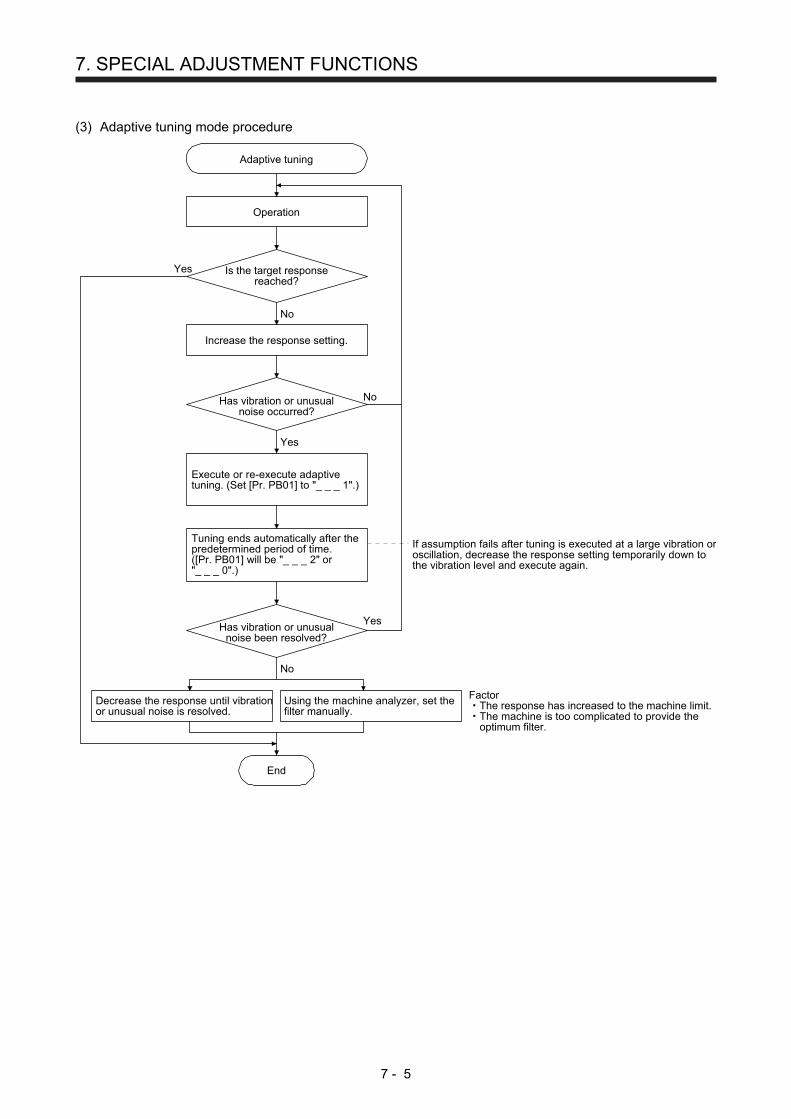
7. SPECIAL ADJUSTMENT FUNCTIONS
7 - 5
(3) Adaptive tuning mode procedure
Tuning ends automatically after thepredetermined period of time.([Pr. PB01] will be "_ _ _ 2" or"_ _ _ 0".)
Adaptive tuning
Operation
Is the target responsereached?
Decrease the response until vibrationor unusual noise is resolved.
End
Yes
No
No
Yes
Increase the response setting.
Has vibration or unusualnoise occurred?
Has vibration or unusualnoise been resolved?
Using the machine analyzer, set thefilter manually.
Yes
No
Execute or re-execute adaptivetuning. (Set [Pr. PB01] to "_ _ _ 1".)
FactorThe response has increased to the machine limit.The machine is too complicated to provide theoptimum filter.
If assumption fails after tuning is executed at a large vibration oroscillation, decrease the response setting temporarily down tothe vibration level and execute again.

7. SPECIAL ADJUSTMENT FUNCTIONS
7 - 6
7.1.3 Shaft resonance suppression filter
POINT
This filter is set properly by default according to servo motor you use and load
moment of inertia. For [Pr. PB23], "_ _ _ 0" (automatic setting) is recommended
because setting "Shaft resonance suppression filter selection" in [Pr. PB23] or
setting [Pr. PB17 Shaft resonance suppression filter] can degrades in
performance.
(1) Function
When a load is mounted to the servo motor shaft, resonance by shaft torsion during driving may
generate a mechanical vibration at high frequency. The shaft resonance suppression filter suppresses
the vibration.
When you select "Automatic setting", the filter will be set automatically on the basis of the servo motor
you use and the load to motor inertia ratio. The disabled setting increases the response of the servo
amplifier for high resonance frequency.
(2) Parameter
Set "Shaft resonance suppression filter selection" in [Pr. PB23].
[Pr. PB23]
Shaft resonance suppression filter selection0: Automatic setting1: Manual setting2: Disabled
0 1 0
To set [Pr. PB17 Shaft resonance suppression filter] automatically, select "Automatic setting".
To set [Pr. PB17 Shaft resonance suppression filter] manually, select "Manual setting". The setting
values are as follows.
Shaft resonance suppression filter setting frequency selection
Setting value Frequency [Hz] Setting value Frequency [Hz]
_ _ 0 0 Disabled _ _ 1 0 562
_ _ 0 1 Disabled _ _ 1 1 529
_ _ 0 2 4500 _ _ 1 2 500
_ _ 0 3 3000 _ _ 1 3 473
_ _ 0 4 2250 _ _ 1 4 450
_ _ 0 5 1800 _ _ 1 5 428
_ _ 0 6 1500 _ _ 1 6 409
_ _ 0 7 1285 _ _ 1 7 391
_ _ 0 8 1125 _ _ 1 8 375
_ _ 0 9 1000 _ _ 1 9 360
_ _ 0 A 900 _ _ 1 A 346
_ _ 0 B 818 _ _ 1 B 333
_ _ 0 C 750 _ _ 1 C 321
_ _ 0 D 692 _ _ 1 D 310
_ _ 0 E 642 _ _ 1 E 300
_ _ 0 F 600 _ _ 1 F 290
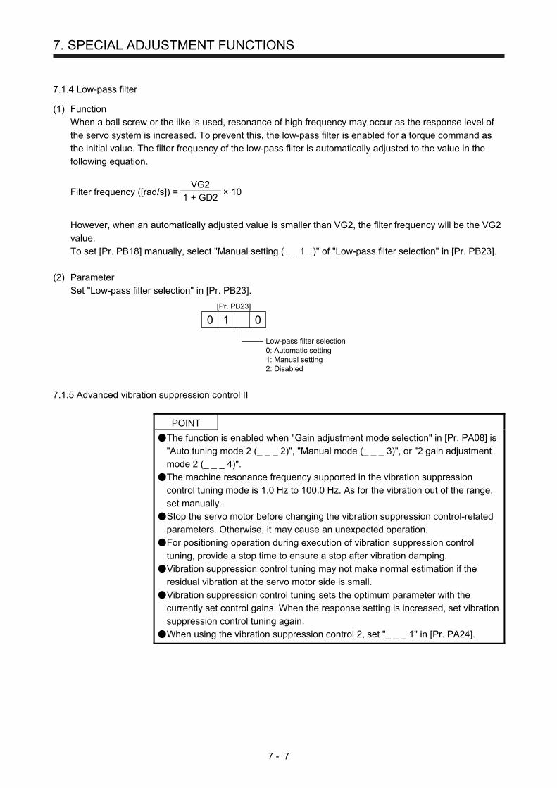
7. SPECIAL ADJUSTMENT FUNCTIONS
7 - 7
7.1.4 Low-pass filter
(1) Function
When a ball screw or the like is used, resonance of high frequency may occur as the response level of
the servo system is increased. To prevent this, the low-pass filter is enabled for a torque command as
the initial value. The filter frequency of the low-pass filter is automatically adjusted to the value in the
following equation.
Filter frequency ([rad/s]) = 1 + GD2
VG2 × 10
However, when an automatically adjusted value is smaller than VG2, the filter frequency will be the VG2
value.
To set [Pr. PB18] manually, select "Manual setting (_ _ 1 _)" of "Low-pass filter selection" in [Pr. PB23].
(2) Parameter
Set "Low-pass filter selection" in [Pr. PB23].
[Pr. PB23]
Low-pass filter selection0: Automatic setting1: Manual setting2: Disabled
0 1 0
7.1.5 Advanced vibration suppression control II
POINT
The function is enabled when "Gain adjustment mode selection" in [Pr. PA08] is
"Auto tuning mode 2 (_ _ _ 2)", "Manual mode (_ _ _ 3)", or "2 gain adjustment
mode 2 (_ _ _ 4)".
The machine resonance frequency supported in the vibration suppression
control tuning mode is 1.0 Hz to 100.0 Hz. As for the vibration out of the range,
set manually.
Stop the servo motor before changing the vibration suppression control-related
parameters. Otherwise, it may cause an unexpected operation.
For positioning operation during execution of vibration suppression control
tuning, provide a stop time to ensure a stop after vibration damping.
Vibration suppression control tuning may not make normal estimation if the
residual vibration at the servo motor side is small.
Vibration suppression control tuning sets the optimum parameter with the
currently set control gains. When the response setting is increased, set vibration
suppression control tuning again.
When using the vibration suppression control 2, set "_ _ _ 1" in [Pr. PA24].
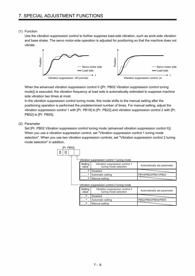
7. SPECIAL ADJUSTMENT FUNCTIONS
7 - 8
(1) Function
Use the vibration suppression control to further suppress load-side vibration, such as work-side vibration
and base shake. The servo motor-side operation is adjusted for positioning so that the machine does not
vibrate.
Vibration suppression: off (normal)
Servo motor side
Load side
t
Pos
ition
Vibration suppression control: on
Servo motor side
Load side
Pos
ition
t
When the advanced vibration suppression control II ([Pr. PB02 Vibration suppression control tuning
mode]) is executed, the vibration frequency at load side is automatically estimated to suppress machine
side vibration two times at most.
In the vibration suppression control tuning mode, this mode shifts to the manual setting after the
positioning operation is performed the predetermined number of times. For manual setting, adjust the
vibration suppression control 1 with [Pr. PB19] to [Pr. PB22] and vibration suppression control 2 with [Pr.
PB52] to [Pr. PB55].
(2) Parameter
Set [Pr. PB02 Vibration suppression control tuning mode (advanced vibration suppression control II)].
When you use a vibration suppression control, set "Vibration suppression control 1 tuning mode
selection". When you use two vibration suppression controls, set "Vibration suppression control 2 tuning
mode selection" in addition.
[Pr. PB02]
Vibration suppression control 1 tuning mode
0 0
_ _ _ 0
_ _ _ 1
_ _ _ 2
Settingvalue
Vibration suppression control 1tuning mode selection
Disabled
Automatic setting
Manual setting
PB19/PB20/PB21/PB22
Automatically set parameter
Vibration suppression control 2 tuning mode
_ _ 0 _
_ _ 1 _
_ _ 2 _
Settingvalue
Vibration suppression control 2tuning mode selection
Disabled
Automatic setting
Manual setting
PB52/PB53/PB54/PB55
Automatically set parameter
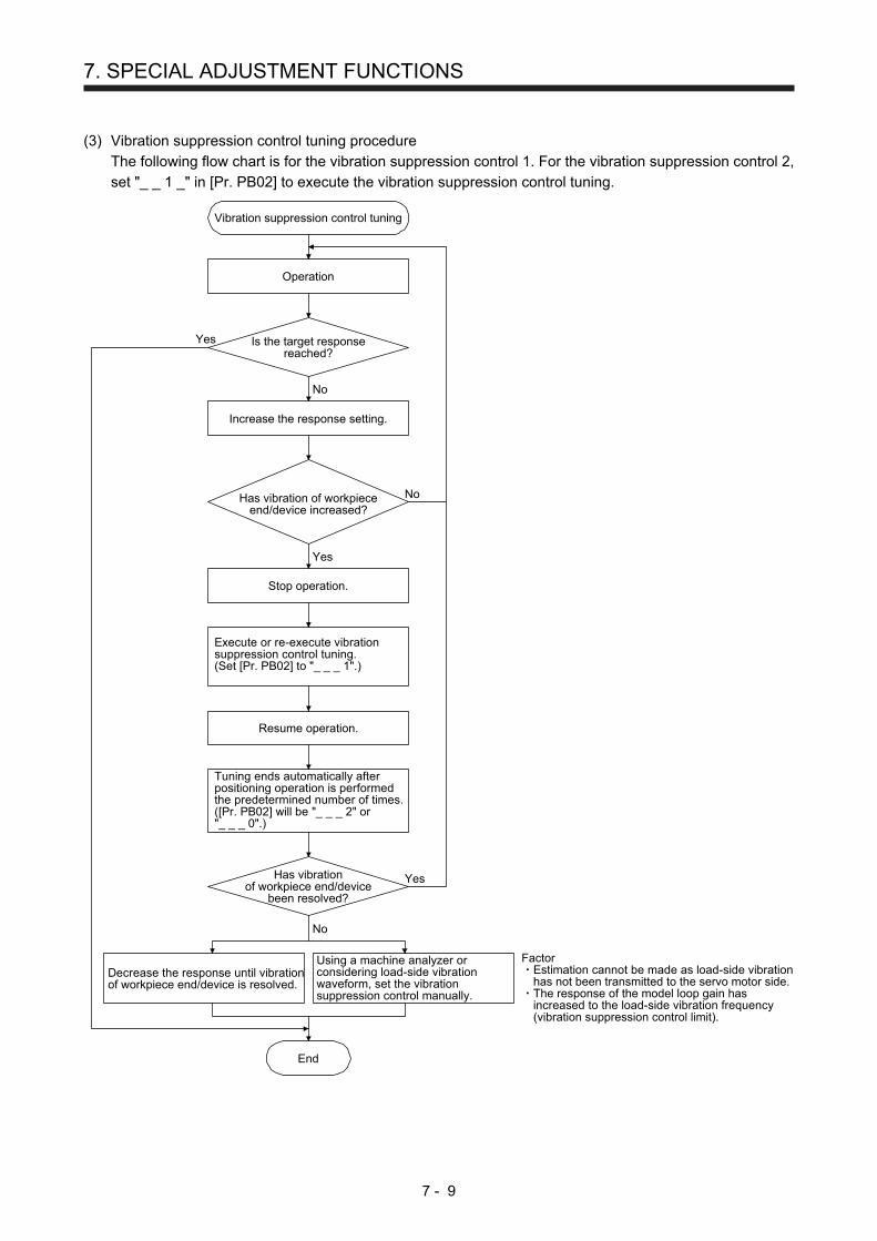
7. SPECIAL ADJUSTMENT FUNCTIONS
7 - 9
(3) Vibration suppression control tuning procedure
The following flow chart is for the vibration suppression control 1. For the vibration suppression control 2,
set "_ _ 1 _" in [Pr. PB02] to execute the vibration suppression control tuning.
No
Vibration suppression control tuning
Operation
Is the target responsereached?
Execute or re-execute vibrationsuppression control tuning.(Set [Pr. PB02] to "_ _ _ 1".)
Decrease the response until vibrationof workpiece end/device is resolved.
End
Yes
No
No
Yes
Increase the response setting.
Has vibration of workpieceend/device increased?
Has vibrationof workpiece end/device
been resolved?
Using a machine analyzer orconsidering load-side vibrationwaveform, set the vibrationsuppression control manually.
FactorEstimation cannot be made as load-side vibrationhas not been transmitted to the servo motor side.The response of the model loop gain hasincreased to the load-side vibration frequency(vibration suppression control limit).
Yes
Tuning ends automatically afterpositioning operation is performedthe predetermined number of times.([Pr. PB02] will be "_ _ _ 2" or"_ _ _ 0".)
Stop operation.
Resume operation.

7. SPECIAL ADJUSTMENT FUNCTIONS
7 - 10
(4) Vibration suppression control manual mode
POINT
When load-side vibration does not show up in servo motor-side vibration, the
setting of the servo motor-side vibration frequency does not produce an effect.
When the anti-resonance frequency and resonance frequency can be confirmed
using the machine analyzer or external equipment, do not set the same value
but set different values to improve the vibration suppression performance.
Measure work-side vibration and device shake with the machine analyzer or external measuring
instrument, and set the following parameters to adjust vibration suppression control manually.
Setting item Vibration suppression
control 1 Vibration suppression
control 2
Vibration suppression control - Vibration frequency
[Pr. PB19] [Pr. PB52]
Vibration suppression control - Resonance frequency
[Pr. PB20] [Pr. PB53]
Vibration suppression control - Vibration frequency damping
[Pr. PB21] [Pr. PB54]
Vibration suppression control - Resonance frequency damping
[Pr. PB22] [Pr. PB55]
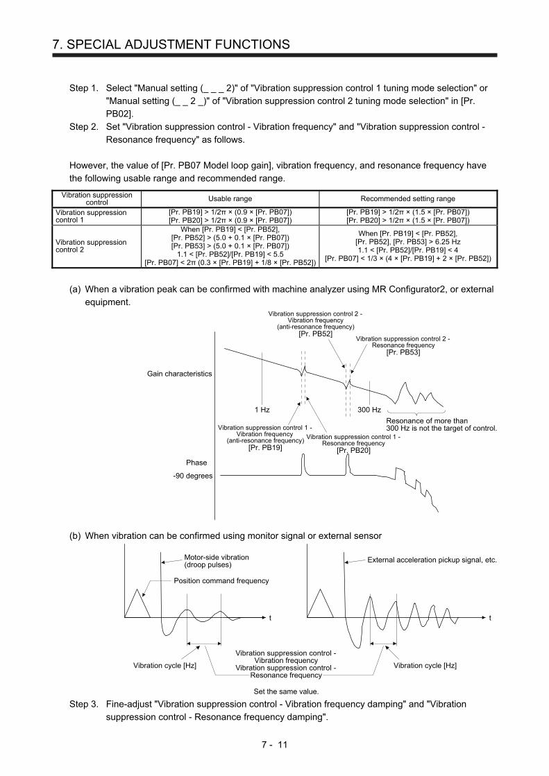
7. SPECIAL ADJUSTMENT FUNCTIONS
7 - 11
Step 1. Select "Manual setting (_ _ _ 2)" of "Vibration suppression control 1 tuning mode selection" or
"Manual setting (_ _ 2 _)" of "Vibration suppression control 2 tuning mode selection" in [Pr.
PB02].
Step 2. Set "Vibration suppression control - Vibration frequency" and "Vibration suppression control -
Resonance frequency" as follows.
However, the value of [Pr. PB07 Model loop gain], vibration frequency, and resonance frequency have
the following usable range and recommended range.
Vibration suppression control Usable range Recommended setting range
Vibration suppression control 1
[Pr. PB19] > 1/2π × (0.9 × [Pr. PB07])[Pr. PB20] > 1/2π × (0.9 × [Pr. PB07])
[Pr. PB19] > 1/2π × (1.5 × [Pr. PB07])[Pr. PB20] > 1/2π × (1.5 × [Pr. PB07])
Vibration suppression control 2
When [Pr. PB19] < [Pr. PB52],[Pr. PB52] > (5.0 + 0.1 × [Pr. PB07]) [Pr. PB53] > (5.0 + 0.1 × [Pr. PB07])
1.1 < [Pr. PB52]/[Pr. PB19] < 5.5 [Pr. PB07] < 2π (0.3 × [Pr. PB19] + 1/8 × [Pr. PB52])
When [Pr. PB19] < [Pr. PB52], [Pr. PB52], [Pr. PB53] > 6.25 Hz 1.1 < [Pr. PB52]/[Pr. PB19] < 4
[Pr. PB07] < 1/3 × (4 × [Pr. PB19] + 2 × [Pr. PB52])
(a) When a vibration peak can be confirmed with machine analyzer using MR Configurator2, or external
equipment.
1 Hz
Gain characteristics
Phase
-90 degrees
300 Hz
Vibration suppression control 1 -Vibration frequency
(anti-resonance frequency)[Pr. PB19]
Vibration suppression control 1 -Resonance frequency
[Pr. PB20]
Vibration suppression control 2 -Vibration frequency
(anti-resonance frequency)[Pr. PB52]
Vibration suppression control 2 -Resonance frequency
[Pr. PB53]
Resonance of more than300 Hz is not the target of control.
(b) When vibration can be confirmed using monitor signal or external sensor
t
Motor-side vibration(droop pulses)
Position command frequency
t
External acceleration pickup signal, etc.
Vibration suppression control -Vibration frequency
Vibration suppression control -Resonance frequency
Set the same value.
Vibration cycle [Hz] Vibration cycle [Hz]
Step 3. Fine-adjust "Vibration suppression control - Vibration frequency damping" and "Vibration
suppression control - Resonance frequency damping".

7. SPECIAL ADJUSTMENT FUNCTIONS
7 - 12
7.1.6 Command notch filter
POINT
By using the advanced vibration suppression control II and the command notch
filter, the load-side vibration of three frequencies can be suppressed.
The frequency range of machine vibration, which can be supported by the
command notch filter, is between 4.5 Hz and 2250 Hz. Set a frequency close to
the machine vibration frequency and within the range.
When [Pr. PB45 Command notch filter] is changed during the positioning
operation, the changed setting is not reflected. The setting is reflected
approximately 150 ms after the servo motor stops (after servo-lock).
(1) Function
Command notch filter has a function that lowers the gain of the specified frequency contained in a
position command. By lowering the gain, load-side vibration, such as work-side vibration and base
shake, can be suppressed. Which frequency to lower the gain and how deep to lower the gain can be
set.
Pos
ition
Load side
t
Command notch filter: disabled
Load side
t
Pos
ition
Command notch filter: enabled

7. SPECIAL ADJUSTMENT FUNCTIONS
7 - 13
(2) Parameter
Set [Pr. PB45 Command notch filter] as shown below. For the command notch filter setting frequency,
set the closest value to the vibration frequency [Hz] at the load side.
Settingvalue
Command notch filter setting frequency
Settingvalue
Frequency[Hz]
00
01
02
03
0
Frequency[Hz]
Settingvalue
Frequency[Hz]
04
05
06
07
08
09
0A
0B
0C
0D
0E
0F
10
11
12
13
14
15
16
17
18
19
1A
1B
1C
1D
1E
1F
20
21
22
23
24
25
26
27
28
29
2A
2B
2C
2D
2E
2F
30
31
32
33
34
35
36
37
38
39
3A
3B
3C
3D
3E
3F
40
41
42
43
44
45
46
47
48
49
4A
4B
4C
4D
4E
4F
50
51
52
53
54
55
56
57
58
59
5A
5B
5C
5D
5E
5F
Disabled
2250
1125
750
562
450
375
321
281
250
225
204
187
173
160
150
140
132
125
118
112
107
102
97
93
90
86
83
80
77
75
72
70
66
62
59
56
53
51
48
46
45
43
41
40
38
37
36
35.2
33.1
31.3
29.6
28.1
26.8
25.6
24.5
23.4
22.5
21.6
20.8
20.1
19.4
18.8
18.2
17.6
16.5
15.6
14.8
14.1
13.4
12.8
12.2
11.7
11.3
10.8
10.4
10.0
9.7
9.4
9.1
8.8
8.3
7.8
7.4
7.0
6.7
6.4
6.1
5.9
5.6
5.4
5.2
5.0
4.9
4.7
4.5
Notch depth
0
1
2
3
4
5
6
7
8
9
A
B
C
D
E
F
Settingvalue
Depth[dB]
[Pr. PB45]
-40.0
-24.1
-18.1
-14.5
-12.0
-10.1
-8.5
-7.2
-6.0
-5.0
-4.1
-3.3
-2.5
-1.8
-1.2
-0.6
7.2 Gain switching function
You can switch gains with the function. You can switch gains during rotation and during stop, and can use an
input device to switch gains during operation.
7.2.1 Applications
The following shows when you use the function.
(1) You want to increase the gains during servo-lock but decrease the gains to reduce noise during rotation.
(2) You want to increase the gains during settling to shorten the stop settling time.
(3) You want to change the gains using an input device to ensure stability of the servo system since the
load to motor inertia ratio varies greatly during a stop (e.g. a large load is mounted on a carrier).

7. SPECIAL ADJUSTMENT FUNCTIONS
7 - 14
7.2.2 Function block diagram
The control gains, load to motor inertia ratio, and vibration suppression control settings are changed
according to the conditions selected by [Pr. PB26 Gain switching function] and [Pr. PB27 Gain switching
condition].
Command pulsefrequency
+-
Droop pulses
Model speed
Input device (CDP)
Comparator
Changing
CDP[Pr. PB26]
+-
+-
GD2[Pr. PB06]
GD2B[Pr. PB29]
EnabledGD2 value
PG1[Pr. PB07]
PG1B[Pr. PB60]
EnabledPG1 value
PG2[Pr. PB08]
PG2B[Pr. PB30]
EnabledPG2 value
VG2[Pr. PB09]
VG2B[Pr. PB31]
EnabledVG2 value
VIC[Pr. PB10]
VICB[Pr. PB32]
EnabledVIC value
VRF11[Pr. PB19]
VRF11B[Pr. PB33]
EnabledVRF11 value
VRF12[Pr. PB20]
VRF12B[Pr. PB34]
EnabledVRF12 value
CDL[Pr. PB27]
VRF13[Pr. PB21]
VRF13B[Pr. PB35]
EnabledVRF13 value
VRF14[Pr. PB22]
VRF14B[Pr. PB36]
EnabledVRF14 value
VRF21[Pr. PB52]
VRF21B[Pr. PB56]
EnabledVRF21 value
VRF22[Pr. PB53]
VRF22B[Pr. PB57]
EnabledVRF22 value
VRF23[Pr. PB54]
VRF23B[Pr. PB58]
EnabledVRF23 value
VRF24[Pr. PB55]
VRF24B[Pr. PB59]
EnabledVRF24 value

7. SPECIAL ADJUSTMENT FUNCTIONS
7 - 15
7.2.3 Parameter
When using the gain switching function, always select "Manual mode (_ _ _ 3)" of "Gain adjustment mode
selection" in [Pr. PA08 Auto tuning mode]. The gain switching function cannot be used in the auto tuning
mode.
(1) Parameter for setting gain switching condition
Parameter Symbol Name Unit Description
PB26 CDP Gain switching selection Select the changing condition.
PB27 CDL Gain switching condition [kpulse/s]/[pulse] /[r/min]
Set the changing condition values.
PB28 CDT Gain switching time constant [ms] You can set the filter time constant for a gain change at changing.
(a) [Pr. PB26 Gain switching function]
Set the gain switching condition. Select the switching condition in the first to third digits.
Gain switching selection0: Disabled1: Input device (gain switching (CDP))2: Command frequency3: Droop pulses4: Servo motor speed
0
Gain switching condition0: Gain after switching is enabled with gain switching condition or more1: Gain after switching is enabled with gain switching condition or less
[Pr. PB26]
Gain switching time constant disabling condition selection (Note)0: Switching time constant enabled1: Switching time constant disabled2: Return time constant disabled
Note. This parameter setting is available with servo amplifiers with software version B4 or
later.
(b) [Pr. PB27 Gain switching condition]
Set a level to switch gains after you select "Command frequency", "Droop pulses", or "Servo motor
speed" in [Pr. PB26 Gain switching function].
The setting unit is as follows.
Gain switching condition Unit
Command frequency [kpulse/s]
Droop pulses [pulse]
Servo motor speed [r/min]
(c) [Pr. PB28 Gain switching time constant]
You can set the primary delay filter to each gain at gain switching. Use this parameter to suppress
shock given to the machine if the gain difference is large at gain switching, for example.

7. SPECIAL ADJUSTMENT FUNCTIONS
7 - 16
(2) Switchable gain parameter
Loop gain Before switching After switching
Parameter Symbol Name Parameter Symbol Name
Load to motor inertia ratio PB06 GD2 Load to motor inertia ratio PB29 GD2B Load to motor inertia ratio after gain switching
Model loop gain PB07 PG1 Model loop gain PB60 PG1B Gain switching Model loop gain
Position loop gain PB08 PG2 Position loop gain PB30 PG2B Gain switching Position loop gain
Speed loop gain PB09 VG2 Speed loop gain PB31 VG2B Gain switching Speed loop gain
Speed integral compensation
PB10 VIC Speed integral compensation
PB32 VICB Gain switching Speed integral compensation
Vibration suppression control 1 Used to set the value of the after-changing vibration suppression control vibration frequency setting.
PB19 VRF11 Vibration suppression control 1 Used to set the value of the after-changing vibration suppression control vibration frequency setting.
PB33 VRF11B Vibration suppression control 1 - Vibration frequency after gain switching
Vibration suppression control 1 - Resonance frequency
PB20 VRF12 Vibration suppression control 1 - Resonance frequency
PB34 VRF12B Vibration suppression control 1 - Resonance frequency after gain switching
Vibration suppression control 1 - Vibration frequency damping
PB21 VRF13 Vibration suppression control 1 - Vibration frequency damping
PB35 VRF13B Vibration suppression control 1 - Vibration frequency damping after gain switching
Vibration suppression control 1 - Resonance frequency damping
PB22 VRF14 Vibration suppression control 1 - Resonance frequency damping
PB36 VRF14B Vibration suppression control 1 - Resonance frequency damping after gain switching
Vibration suppression control 2 - Vibration frequency
PB52 VRF21 Vibration suppression control 2 - Vibration frequency
PB56 VRF21B Vibration suppression control 2 - Vibration frequency after gain switching
Vibration suppression control 2 - Resonance frequency
PB53 VRF22 Vibration suppression control 2 - Resonance frequency
PB57 VRF22B Vibration suppression control 2 - Resonance frequency after gain switching
Vibration suppression control 2 - Vibration frequency damping
PB54 VRF23 Vibration suppression control 2 - Vibration frequency damping
PB58 VRF23B Vibration suppression control 2 - Vibration frequency damping after gain switching
Vibration suppression control 2 - Resonance frequency damping
PB55 VRF24 Vibration suppression control 2 - Resonance frequency damping
PB59 VRF24B Vibration suppression control 2 - Resonance frequency damping after gain switching
(a) [Pr. PB06] to [Pr. PB10]
These parameters are the same as in ordinary manual adjustment. Gain switching allows the values
of load to motor inertia ratio, position loop gain, speed loop gain, and speed integral compensation to
be switched.
(b) [Pr.PB19] to [Pr.PB22]/[Pr.PB52] to [Pr.PB55]
These parameters are the same as in ordinary manual adjustment. You can switch the vibration
frequency, resonance frequency, vibration frequency damping, and resonance frequency damping
by switching gain during motor stop.

7. SPECIAL ADJUSTMENT FUNCTIONS
7 - 17
(c) [Pr. PB29 Load to motor inertia ratio after gain switching]
Set the load to motor inertia ratio after gain switching. If the load to motor inertia ratio does not
change, set it to the same value as [Pr. PB06 Load to motor inertia ratio].
(d) [Pr. PB30 Position loop gain after gain switching], [Pr. PB31 Speed loop gain after gain switching],
and [Pr. PB32 Speed integral compensation after gain switching]
Set the values of after switching position loop gain, speed loop gain and speed integral
compensation.
(e) Vibration suppression control after gain switching ([Pr. PB33] to [Pr. PB36]/[Pr. PB56] to [Pr.
PB59])/[Pr. PB60 Model loop gain after gain switching]
The gain switching vibration suppression control and model loop gain are used only with input device
(CDP) on/off.
You can switch the vibration frequency, resonance frequency, vibration frequency damping,
resonance frequency damping, and model loop gain of the vibration suppression control 1 and
vibration suppression control 2.
7.2.4 Gain switching procedure
This operation will be described by way of setting examples.
(1) When you choose switching by input device (CDP)
(a) Setting
Parameter Symbol Name Setting value Unit
PB06 GD2 Load to motor inertia ratio 4.00 [Multiplier]
PB07 PG1 Model loop gain 100 [rad/s]
PB08 PG2 Position loop gain 120 [rad/s]
PB09 VG2 Speed loop gain 3000 [rad/s]
PB10 VIC Speed integral compensation 20 [ms]
PB19 VRF11 Vibration suppression control 1 - Vibration frequency 50 [Hz]
PB20 VRF12 Vibration suppression control 1 - Resonance frequency 50 [Hz]
PB21 VRF13 Vibration suppression control 1 - Vibration frequency damping 0.20
PB22 VRF14 Vibration suppression control 1 - Resonance frequency damping 0.20
PB52 VRF21 Vibration suppression control 2 - Vibration frequency 20 [Hz]
PB53 VRF22 Vibration suppression control 2 - Resonance frequency 20 [Hz]
PB54 VRF23 Vibration suppression control 2 - Vibration frequency damping 0.10
PB55 VRF24 Vibration suppression control 2 - Resonance frequency damping 0.10
PB29 GD2B Load to motor inertia ratio after gain switching 10.00 [Multiplier]
PB60 PG1B Model loop gain after gain switching 50 [rad/s]
PB30 PG2B Gain switching position loop gain 84 [rad/s]
PB31 VG2B Gain switching speed loop gain 4000 [rad/s]
PB32 VICB Speed integral compensation after gain switching 50 [ms]
PB26 CDP Gain switching function 0001 (Switch by input device (CDP) on/off.)

7. SPECIAL ADJUSTMENT FUNCTIONS
7 - 18
Parameter Symbol Name Setting value Unit
PB28 CDT Gain switching time constant 100 [ms]
PB33 VRF11B Vibration suppression control 1 - Vibration frequency after gain switching
60 [Hz]
PB34 VRF12B Vibration suppression control 1 - Resonance frequency after gain switching
60 [Hz]
PB35 VRF13B Vibration suppression control 1 - Vibration frequency damping after gain switching
0.15
PB36 VRF14B Vibration suppression control 1 - Resonance frequency damping after gain switching
0.15
PB56 VRF21B Vibration suppression control 2 - Vibration frequency after gain switching
30 [Hz]
PB57 VRF22B Vibration suppression control 2 - Resonance frequency after gain switching
30 [Hz]
PB58 VRF23B Vibration suppression control 2 - Vibration frequency damping after gain switching
0.05
PB59 VRF24B Vibration suppression control 2 - Resonance frequency damping after gain switching
0.05
(b) Switching timing chart
After-switching gain
63.4%
CDT = 100 ms
Before-switching gainGain switching
CDP (gain switching)OFF ON OFF
Model loop gain 100 → 50 → 100
Load to motor inertia ratio 4.00 → 10.00 → 4.00
Position loop gain 120 → 84 → 120
Speed loop gain 3000 → 4000 → 3000
Speed integral compensation 20 → 50 → 20
Vibration suppression control 1 - Vibration frequency
50 → 60 → 50
Vibration suppression control 1 - Resonance frequency
50 → 60 → 50
Vibration suppression control 1 - Vibration frequency damping
0.20 → 0.15 → 0.20
Vibration suppression control 1 - Resonance frequency damping
0.20 → 0.15 → 0.20
Vibration suppression control 2 - Vibration frequency
20 → 30 → 20
Vibration suppression control 2 - Resonance frequency
20 → 30 → 20
Vibration suppression control 2 - Vibration frequency damping
0.10 → 0.05 → 0.10
Vibration suppression control 2 - Resonance frequency damping
0.10 → 0.05 → 0.10
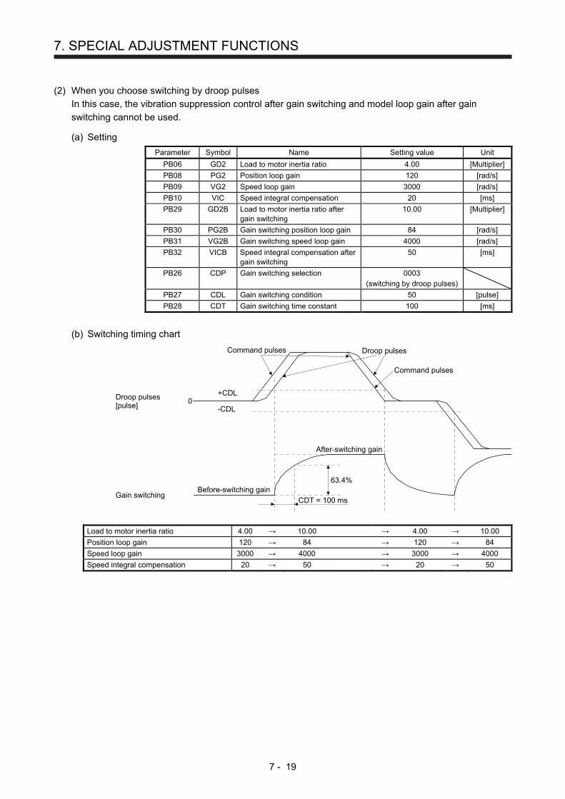
7. SPECIAL ADJUSTMENT FUNCTIONS
7 - 19
(2) When you choose switching by droop pulses
In this case, the vibration suppression control after gain switching and model loop gain after gain
switching cannot be used.
(a) Setting
Parameter Symbol Name Setting value Unit
PB06 GD2 Load to motor inertia ratio 4.00 [Multiplier]
PB08 PG2 Position loop gain 120 [rad/s]
PB09 VG2 Speed loop gain 3000 [rad/s]
PB10 VIC Speed integral compensation 20 [ms]
PB29 GD2B Load to motor inertia ratio after gain switching
10.00 [Multiplier]
PB30 PG2B Gain switching position loop gain 84 [rad/s]
PB31 VG2B Gain switching speed loop gain 4000 [rad/s]
PB32 VICB Speed integral compensation after gain switching
50 [ms]
PB26 CDP Gain switching selection 0003 (switching by droop pulses)
PB27 CDL Gain switching condition 50 [pulse]
PB28 CDT Gain switching time constant 100 [ms]
(b) Switching timing chart
After-switching gain
63.4%
CDT = 100 ms
Before-switching gainGain switching
Droop pulses[pulse]
+CDL
-CDL0
Command pulses Droop pulses
Command pulses
Load to motor inertia ratio 4.00 → 10.00 → 4.00 → 10.00
Position loop gain 120 → 84 → 120 → 84
Speed loop gain 3000 → 4000 → 3000 → 4000
Speed integral compensation 20 → 50 → 20 → 50
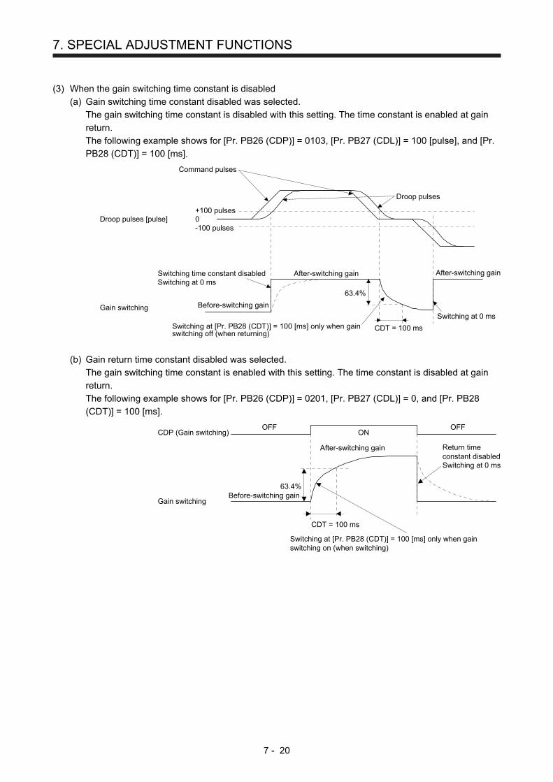
7. SPECIAL ADJUSTMENT FUNCTIONS
7 - 20
(3) When the gain switching time constant is disabled
(a) Gain switching time constant disabled was selected.
The gain switching time constant is disabled with this setting. The time constant is enabled at gain
return.
The following example shows for [Pr. PB26 (CDP)] = 0103, [Pr. PB27 (CDL)] = 100 [pulse], and [Pr.
PB28 (CDT)] = 100 [ms].
Command pulses
Droop pulses
+100 pulses
-100 pulses0Droop pulses [pulse]
Switching time constant disabledSwitching at 0 ms
After-switching gain
Before-switching gain
Switching at [Pr. PB28 (CDT)] = 100 [ms] only when gainswitching off (when returning)
CDT = 100 ms
63.4%
Switching at 0 ms
After-switching gain
Gain switching
(b) Gain return time constant disabled was selected.
The gain switching time constant is enabled with this setting. The time constant is disabled at gain
return.
The following example shows for [Pr. PB26 (CDP)] = 0201, [Pr. PB27 (CDL)] = 0, and [Pr. PB28
(CDT)] = 100 [ms].
ONCDP (Gain switching)
After-switching gain
Before-switching gain
Switching at [Pr. PB28 (CDT)] = 100 [ms] only when gainswitching on (when switching)
CDT = 100 ms
Return timeconstant disabledSwitching at 0 ms
OFF OFF
63.4%
Gain switching
7. SPECIAL ADJUSTMENT FUNCTIONS
7 - 21
7.3 Tough drive function
POINT
Set enable/disable of the tough drive function with [Pr. PA20 Tough drive
setting]. (Refer to section 5.2.1.)
This function makes the equipment continue operating even under the condition that an alarm occurs. The
tough drive functions are the vibration tough drive and the instantaneous power failure tough drive.
7.3.1 Vibration tough drive function
This function prevents vibration by resetting a filter instantaneously when machine resonance occurs due to
varied vibration frequency caused by machine aging.
To reset the machine resonance suppression filters with the function, [Pr. PB13 Machine resonance
suppression filter 1] and [Pr. PB15 Machine resonance suppression filter 2] should be set in advance.
Set [Pr. PB13] and [Pr. PB15] as follows.
(1) One-touch tuning execution (section 6.2)
(2) Manual setting (section 5.2.2)
The vibration tough drive function operates when a detected machine resonance frequency is within ±30%
for a value set in [Pr. PB13 Machine resonance suppression filter 1] or [Pr. PB15 Machine resonance
suppression filter 2].
To set a detection level of the function, set sensitivity in [Pr. PF23 Vibration tough drive - Oscillation
detection level].
POINT
Resetting [Pr. PB13] and [Pr. PB15] by the vibration tough drive function is
performed constantly. However, the number of write times to the EEPROM is
limited to once per hour.
The vibration tough drive function does not reset [Pr. PB46 Machine resonance
suppression filter 3], [Pr. PB48 Machine resonance suppression filter 4], and [Pr.
PB50 Machine resonance suppression filter 5].
The vibration tough drive function does not detect a vibration of 100 Hz or less.

7. SPECIAL ADJUSTMENT FUNCTIONS
7 - 22
The following shows the function block diagram of the vibration tough drive function.
The function detects machine resonance frequency and compare it with [Pr. PB13] and [Pr. PB15], and reset
a machine resonance frequency of a parameter whose set value is closer.
Filter Setting parameter Precaution Parameter that is
reset with vibration tough drive function
Machine resonance suppression filter 1
PB01/PB13/PB14 The filter can be set automatically with "Filter tuning mode selection" in [Pr. PB01].
PB13
Machine resonance suppression filter 2
PB15/PB16 PB15
Machine resonance suppression filter 3
PB46/PB47
Machine resonance suppression filter 4
PB48/PB49 Enabling the machine resonance suppression filter 4 disables the shaft resonance suppression filter. Using the shaft resonance suppression filter is recommended because it is adjusted properly depending on the usage situation. The shaft resonance suppression filter is enabled for the initial setting.
Machine resonance suppression filter 5
PB50/PB51 Enabling the robust filter disables the machine resonance suppression filter 5. The robust filter is disabled for the initial setting.
Commandpulse train
Commandfilter
Encoder
Servo motor
PWM M
Load
+-
Machineresonance
suppressionfilter 1
[Pr. PB13] [Pr. PB15] [Pr. PB46]Machine
resonancesuppression
filter 2
Machineresonance
suppressionfilter 3
Machineresonance
suppressionfilter 4
Machineresonance
suppressionfilter 5
Shaftresonance
suppressionfilter
Robust filter
[Pr. PB48] [Pr. PB50]
[Pr. PB17]
[Pr. PB49] [Pr. PE41]
Updates the parameterwhose setting is theclosest to the machineresonance frequency.
Vibration tough drive
Torque
ALM(Malfunction)
WNG(Warning)
MTTR(During tough drive)
ON
OFF
[Pr. PF23 Vibration tough drive - Oscillation detection level]
Detects the machine resonance and reconfigures the filter automatically.
During tough drive (MTTR) is not turned on in the vibration tough drive function.
ON
OFF
ON
OFF
5 s
7. SPECIAL ADJUSTMENT FUNCTIONS
7 - 23
7.3.2 Instantaneous power failure tough drive function
CAUTION The tolerance against instantaneous power failure is increased by the
instantaneous power failure tough drive function. However, it is not guarantee to
comply with the SEMI-F47 standard.
The instantaneous power failure tough drive function avoids [AL. 10 Undervoltage] even when an
instantaneous power failure occurs during operation. When the instantaneous power failure tough drive
activates, the function will increase the tolerance against instantaneous power failure using the electrical
energy charged in the capacitor in the servo amplifier and will change an alarm level of [AL. 10
Undervoltage] simultaneously. The [AL. 10.1 Voltage drop in the power] detection time for the power supply
can be changed by [Pr. PF25 Instantaneous power failure tough drive - detection time]. In addition, [AL.10.2
Bus voltage drop] detection level for the bus voltage is changed automatically.
POINT
MBR (Electromagnetic brake interlock) will not turn off during the instantaneous
power failure tough drive.
Selecting "Enabled (_ _ _ 1)" for "Torque limit function selection at
instantaneous power failure" in [Pr. PA26] will limit torques to save electric
energy when an instantaneous power failure occurs during operation and will
make [AL. 10 Undervoltage] less likely to occur.
When the load of instantaneous power failure is large, the undervoltage alarm
([AL. 10.2]) caused by the bus voltage drop may occur regardless of the set
value of [Pr. PF25 Instantaneous power failure tough drive - detection time].
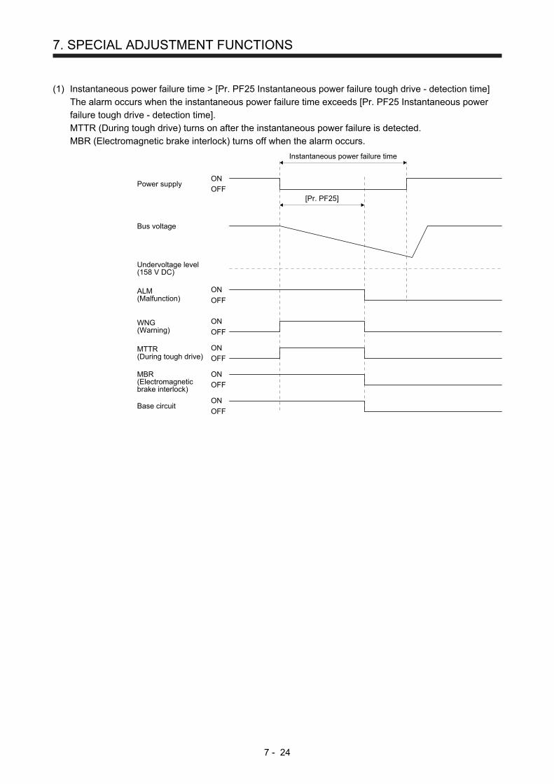
7. SPECIAL ADJUSTMENT FUNCTIONS
7 - 24
(1) Instantaneous power failure time > [Pr. PF25 Instantaneous power failure tough drive - detection time]
The alarm occurs when the instantaneous power failure time exceeds [Pr. PF25 Instantaneous power
failure tough drive - detection time].
MTTR (During tough drive) turns on after the instantaneous power failure is detected.
MBR (Electromagnetic brake interlock) turns off when the alarm occurs.
Power supply
Bus voltage
Undervoltage level(158 V DC)
ALM(Malfunction)
[Pr. PF25]
Instantaneous power failure time
MTTR(During tough drive)
MBR(Electromagneticbrake interlock)
Base circuit
ON
OFF
ON
OFF
ON
OFF
WNG(Warning)
ON
OFF
ON
OFF
ON
OFF

7. SPECIAL ADJUSTMENT FUNCTIONS
7 - 25
(2) Instantaneous power failure time < [Pr. PF25 Instantaneous power failure tough drive - detection time]
Operation status differs depending on how bus voltage decrease.
(a) When the bus voltage decreases lower than 158 V DC within the instantaneous power failure time
[AL. 10 Undervoltage] occurs when the bus voltage decrease lower than 158 V DC regardless of the
enabled instantaneous power failure tough drive.
Power supply
Bus voltage
Undervoltage level(158 V DC)
ALM(Malfunction)
[Pr. PF25]
Instantaneous power failure time
MTTR(During tough drive)
MBR(Electromagneticbrake interlock)
Base circuit
ON
OFF
ON
OFF
ON
OFF
WNG(Warning)
ON
OFF
ON
OFF
ON
OFF
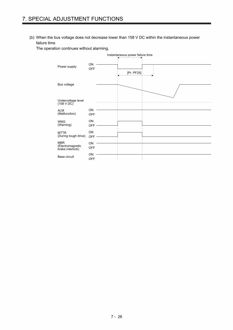
7. SPECIAL ADJUSTMENT FUNCTIONS
7 - 26
(b) When the bus voltage does not decrease lower than 158 V DC within the instantaneous power
failure time
The operation continues without alarming.
Power supply
Bus voltage
Undervoltage level(158 V DC)
ALM(Malfunction)
[Pr. PF25]
Instantaneous power failure time
MTTR(During tough drive)
MBR(Electromagneticbrake interlock)
Base circuit
ON
OFF
ON
OFF
ON
OFF
ON
OFF
ON
OFF
WNG(Warning)
ON
OFF
7. SPECIAL ADJUSTMENT FUNCTIONS
7 - 27
7.4 Model adaptive control disabled
POINT
Change the parameters while the servo motor stops.
When setting auto tuning response ([Pr. PA09]), change the setting value one by
one to adjust it while checking operation status of the servo motor.
This is used with servo amplifiers with software version B4 or later. Check the
software version of the servo amplifier using MR Configurator2.
(1) Summary
The servo amplifier has a model adaptive control. The servo amplifier has a virtual motor model and
drives the servo motor following the output of the motor model in the model adaptive control. At model
adaptive control disabled, the servo amplifier drives the motor with PID control without using the model
adaptive control.
The following shows the available parameters at model adaptive control disabled.
Parameter Symbol Name
PB08 PG2 Position loop gain
PB09 VG2 Speed loop gain
PB10 VIC Speed integral compensation
(2) Parameter setting
Set [Pr. PB25] to "_ _ _ 2".
(3) Restrictions
The following functions are not available at model adaptive control disabled.
Function Explanation
Forced stop deceleration function ([Pr. PA04])
Disabling the model adaptive control while the forced stop deceleration function is enabled, [AL. 37] will occur. The forced stop deceleration function is enabled at factory setting. Set [Pr. PA04] to "0 _ _ _" (Forced stop deceleration function disabled).
Vibration suppression control 1 ([Pr. PB02]/[Pr. PB19]/[Pr. PB20])
Vibration suppression control 2 ([Pr. PB02]/[Pr. PB52]/[Pr. PB53])
The vibration suppression control uses the model adaptive control. Disabling the model adaptive control will also disable the vibration suppression control.
Overshoot amount compensation ([Pr. PB12])
The overshoot amount compensation uses data used by the model adaptive control. Disabling the model adaptive control will also disable the overshoot amount compensation.

7. SPECIAL ADJUSTMENT FUNCTIONS
7 - 28
MEMO
8. TROUBLESHOOTING
8 - 1
8. TROUBLESHOOTING
POINT
Refer to "MELSERVO-JE Servo Amplifier Instruction Manual (Troubleshooting)"
for details of alarms and warnings.
As soon as an alarm occurs, turn SON (Servo-on) off and interrupt the power.
[AL. 37 Parameter error] and warnings (except [AL. F0 Tough drive warning])
are not recorded in the alarm history.
When an error occurs during operation, the corresponding alarm or warning is displayed. When the alarm or
the warning occurs, refer to "MELSERVO-JE Servo Amplifier Instruction Manual (Troubleshooting)" to
remove the failure. When an alarm occurs, ALM (Malfunction) will turn off.
8.1 Explanations of the lists
(1) No./Name/Detail No./Detail name
Indicates the No./name/detail No./detail name of alarms or warnings.
(2) Stop method
For the alarms and warnings in which "SD" is written in the stop method column, the servo motor stops
with the dynamic brake after forced stop deceleration. For the alarms and warnings in which "DB" or
"EDB" is written in the stop method column, the servo motor stops with the dynamic brake without forced
stop deceleration.
(3) Alarm deactivation
After its cause has been removed, the alarm can be deactivated in any of the methods marked in the
alarm deactivation column. Warnings are automatically canceled after the cause of occurrence is
removed. Alarms are deactivated by alarm reset or power cycling.
Alarm deactivation Explanation
Alarm reset 1. Turn on RES (Reset) with an input device. 2. Push the "SET" button while the display of the servo amplifier is in the current
alarm display mode. 3. Click the "Occurring Alarm Reset" button in the "Alarm Display" window of MR
Configurator2.
Cycling the power Turn off the power, check that the 5-digit, 7-segment LED display is off, and then turn on the power.
(4) Alarm code
To output alarm codes, set [Pr. PD34] to "_ _ _ 1". Alarm codes are outputted by turning on/off bit 0 to bit
2. Warnings ([AL. 90] to [AL. F3]) do not have alarm codes. The alarm codes in the following table will be
outputted when they occur. The alarm codes will not be outputted in normal condition.
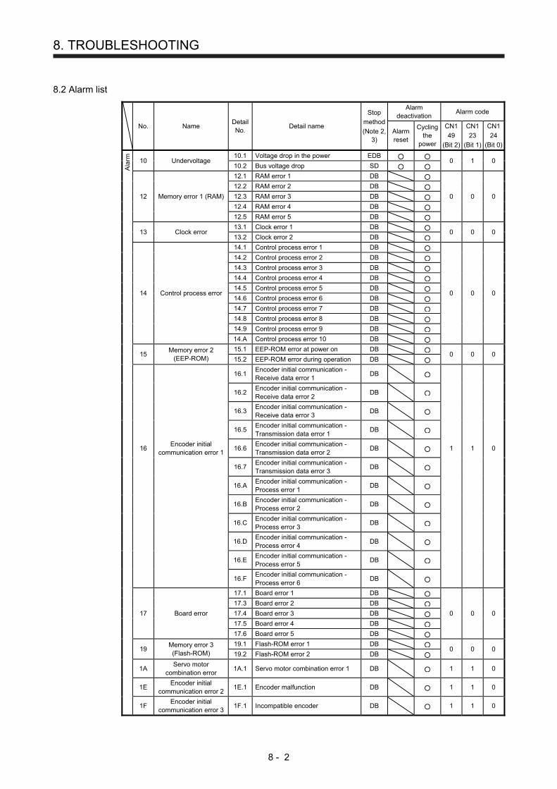
8. TROUBLESHOOTING
8 - 2
8.2 Alarm list
No. Name Detail No.
Detail name
Stop
method
(Note 2, 3)
Alarm deactivation
Alarm code
Alarm reset
Cycling the
power
CN1
49
(Bit 2)
CN1
23
(Bit 1)
CN1
24
(Bit 0)
Ala
rm
10 Undervoltage 10.1 Voltage drop in the power EDB
0 1 0 10.2 Bus voltage drop SD
12.1 RAM error 1 DB
12.2 RAM error 2 DB
12 Memory error 1 (RAM) 12.3 RAM error 3 DB 0 0 0
12.4 RAM error 4 DB
12.5 RAM error 5 DB
13 Clock error
13.1 Clock error 1 DB 0 0 0
13.2 Clock error 2 DB
14.1 Control process error 1 DB
14.2 Control process error 2 DB
14.3 Control process error 3 DB
14.4 Control process error 4 DB
14 Control process error
14.5 Control process error 5 DB 0 0 0
14.6 Control process error 6 DB
14.7 Control process error 7 DB
14.8 Control process error 8 DB
14.9 Control process error 9 DB
14.A Control process error 10 DB
15
Memory error 2 (EEP-ROM)
15.1 EEP-ROM error at power on DB 0 0 0
15.2 EEP-ROM error during operation DB
16.1
Encoder initial communication - Receive data error 1
DB
16.2
Encoder initial communication - Receive data error 2
DB
16.3
Encoder initial communication - Receive data error 3
DB
16.5
Encoder initial communication - Transmission data error 1
DB
16
Encoder initial communication error 1
16.6 Encoder initial communication - Transmission data error 2
DB 1 1 0
16.7
Encoder initial communication - Transmission data error 3
DB
16.A
Encoder initial communication - Process error 1
DB
16.B
Encoder initial communication - Process error 2
DB
16.C
Encoder initial communication - Process error 3
DB
16.D
Encoder initial communication - Process error 4
DB
16.E
Encoder initial communication - Process error 5
DB
16.F
Encoder initial communication - Process error 6
DB
17 Board error
17.1 Board error 1 DB
0 0 0
17.3 Board error 2 DB
17.4 Board error 3 DB
17.5 Board error 4 DB
17.6 Board error 5 DB
19
Memory error 3 (Flash-ROM)
19.1 Flash-ROM error 1 DB 0 0 0
19.2 Flash-ROM error 2 DB
1A
Servo motor combination error
1A.1 Servo motor combination error 1 DB 1 1 0
1E
Encoder initial communication error 2
1E.1 Encoder malfunction DB 1 1 0
1F
Encoder initial communication error 3
1F.1 Incompatible encoder DB 1 1 0
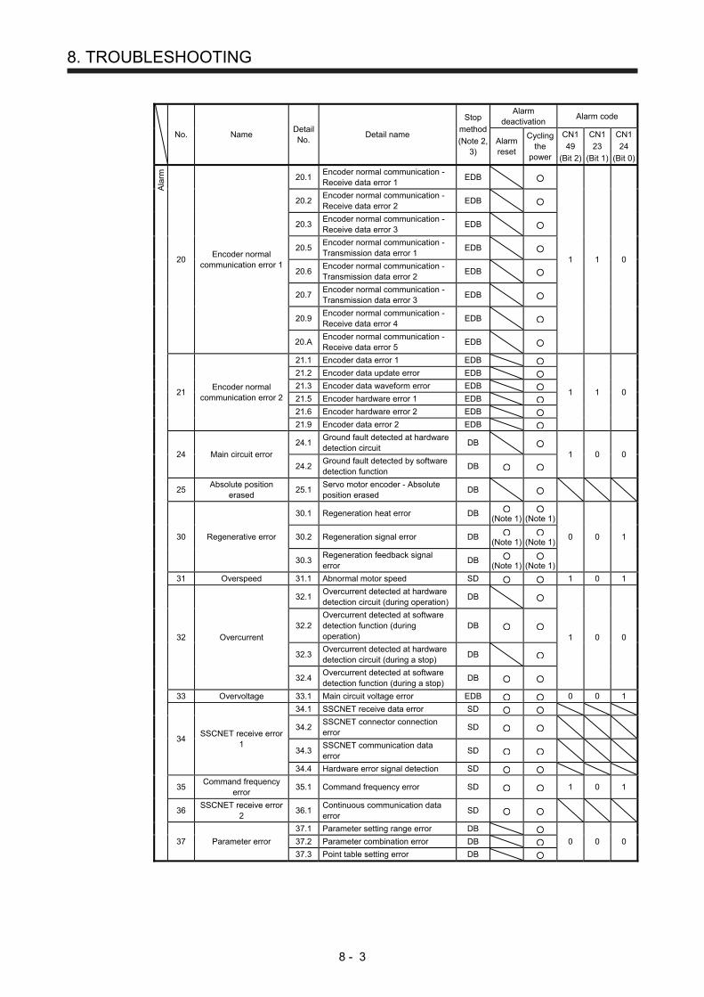
8. TROUBLESHOOTING
8 - 3
No. Name Detail No.
Detail name
Stop
method
(Note 2, 3)
Alarm deactivation
Alarm code
Alarm reset
Cycling the
power
CN1
49
(Bit 2)
CN1
23
(Bit 1)
CN1
24
(Bit 0)A
larm
20.1 Encoder normal communication - Receive data error 1
EDB
20.2 Encoder normal communication - Receive data error 2
EDB
20.3 Encoder normal communication - Receive data error 3
EDB
20 Encoder normal
communication error 1
20.5 Encoder normal communication - Transmission data error 1
EDB 1 1 0
20.6 Encoder normal communication - Transmission data error 2
EDB
20.7
Encoder normal communication - Transmission data error 3
EDB
20.9
Encoder normal communication - Receive data error 4
EDB
20.A
Encoder normal communication - Receive data error 5
EDB
21 Encoder normal
communication error 2
21.1 Encoder data error 1 EDB
1 1 0
21.2 Encoder data update error EDB
21.3 Encoder data waveform error EDB
21.5 Encoder hardware error 1 EDB
21.6 Encoder hardware error 2 EDB
21.9 Encoder data error 2 EDB
24 Main circuit error
24.1 Ground fault detected at hardware detection circuit
DB 1 0 0
24.2
Ground fault detected by software detection function
DB
25
Absolute position erased
25.1 Servo motor encoder - Absolute position erased
DB
30.1 Regeneration heat error DB
(Note 1)
(Note 1)
30 Regenerative error 30.2 Regeneration signal error DB
(Note 1)
(Note 1) 0 0 1
30.3
Regeneration feedback signal error
DB (Note 1)
(Note 1)
31 Overspeed 31.1 Abnormal motor speed SD 1 0 1
32.1
Overcurrent detected at hardware detection circuit (during operation)
DB
32 Overcurrent
32.2 Overcurrent detected at software detection function (during operation)
DB 1 0 0
32.3
Overcurrent detected at hardware detection circuit (during a stop)
DB
32.4
Overcurrent detected at software detection function (during a stop)
DB
33 Overvoltage 33.1 Main circuit voltage error EDB 0 0 1
34 SSCNET receive error
1
34.1 SSCNET receive data error SD
34.2
SSCNET connector connection error
SD
34.3
SSCNET communication data error
SD
34.4 Hardware error signal detection SD
35
Command frequency error
35.1 Command frequency error SD 1 0 1
36
SSCNET receive error 2
36.1 Continuous communication data error
SD
37.1 Parameter setting range error DB
37 Parameter error 37.2 Parameter combination error DB 0 0 0
37.3 Point table setting error DB

8. TROUBLESHOOTING
8 - 4
No. Name Detail No.
Detail name
Stop
method
(Note 2, 3)
Alarm deactivation
Alarm code
Alarm reset
Cycling the
power
CN1
49
(Bit 2)
CN1
23
(Bit 1)
CN1
24
(Bit 0)A
larm
39 Program error
39.1 Program error DB
39.2 Command argument external error DB 0 0 0
39.3 Register No. error DB
39.4
Non-correspondence command error
DB
3E Operation mode error
3E.1 Operation mode error DB
3E.6 Operation mode switch error DB 0 0 0
45
Main circuit device overheat
45.1 Main circuit device overheat error 1 SD (Note 1)
(Note 1)
0 1 1
46 Servo motor overheat
46.1 Abnormal temperature of servo motor 1
SD (Note 1)
(Note 1)
0 1 1 46.5 Abnormal temperature of servo motor 3
DB (Note 1)
(Note 1)
46.6 Abnormal temperature of servo motor 4
DB (Note 1)
(Note 1)
47 Cooling fan error 47.2 Cooling fan speed reduction error SD 0 1 1
50.1
Thermal overload error 1 during operation
SD (Note 1)
(Note 1)
50.2 Thermal overload error 2 during operation
SD (Note 1)
(Note 1)
50 Overload 1
50.3 Thermal overload error 4 during operation
SD (Note 1)
(Note 1)
0 1 1
50.4 Thermal overload error 1 during a stop
SD (Note 1)
(Note 1)
50.5 Thermal overload error 2 during a stop
SD (Note 1)
(Note 1)
50.6 Thermal overload error 4 during a stop
SD (Note 1)
(Note 1)
51 Overload 2
51.1 Thermal overload error 3 during operation
DB (Note 1)
(Note 1)
0 1 1
51.2 Thermal overload error 3 during a stop
DB (Note 1)
(Note 1)
52.1 Excess droop pulse 1 SD
52 Error excessive
52.3 Excess droop pulse 2 SD 1 0 1
52.4 Error excessive during 0 torque limit
SD
52.5 Excess droop pulse 3 EDB
54 Oscillation detection 54.1 Oscillation detection error EDB 0 1 1
56 Forced stop error
56.2 Over speed during forced stop EDB 1 1 0
56.3 Estimated distance over during forced stop
EDB
61 Operation error 61.1 Point table setting range error DB 1 0 1
8A
USB communication time-out error/Serial communication time-
out error
8A.1 USB communication time-out error/Serial communication time-out error
SD 0 0 0
8E.1
USB communication receive error/Serial communication receive error
SD
8E.2
USB communication checksum error/Serial communication checksum error
SD
8E
USB communication error/Serial
communication error 8E.3
USB communication character error/Serial communication character error
SD 0 0 0
8E.4
USB communication command error/Serial communication command error
SD
8E.5
USB communication data number error/Serial communication data number error
SD
88888 Watchdog 8888._ Watchdog DB
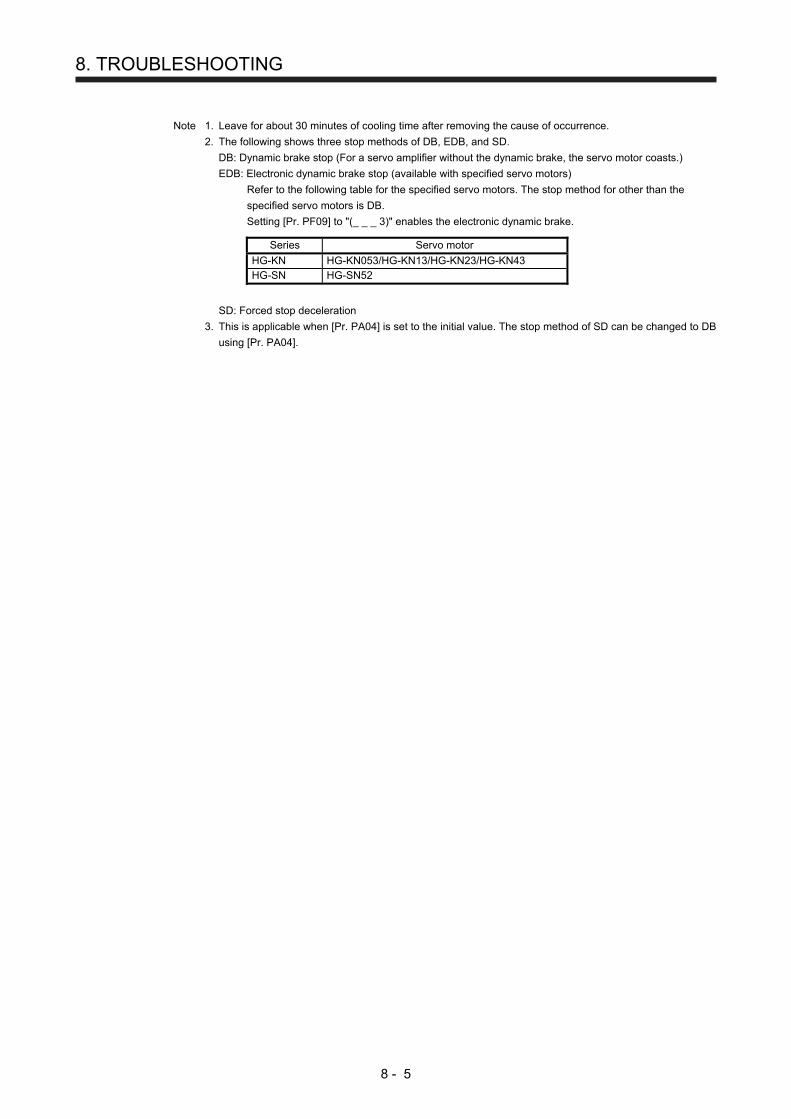
8. TROUBLESHOOTING
8 - 5
Note 1. Leave for about 30 minutes of cooling time after removing the cause of occurrence.
2. The following shows three stop methods of DB, EDB, and SD.
DB: Dynamic brake stop (For a servo amplifier without the dynamic brake, the servo motor coasts.)
EDB: Electronic dynamic brake stop (available with specified servo motors)
Refer to the following table for the specified servo motors. The stop method for other than the
specified servo motors is DB.
Setting [Pr. PF09] to "(_ _ _ 3)" enables the electronic dynamic brake. Series Servo motor
HG-KN HG-KN053/HG-KN13/HG-KN23/HG-KN43 HG-SN HG-SN52
SD: Forced stop deceleration
3. This is applicable when [Pr. PA04] is set to the initial value. The stop method of SD can be changed to DB
using [Pr. PA04].
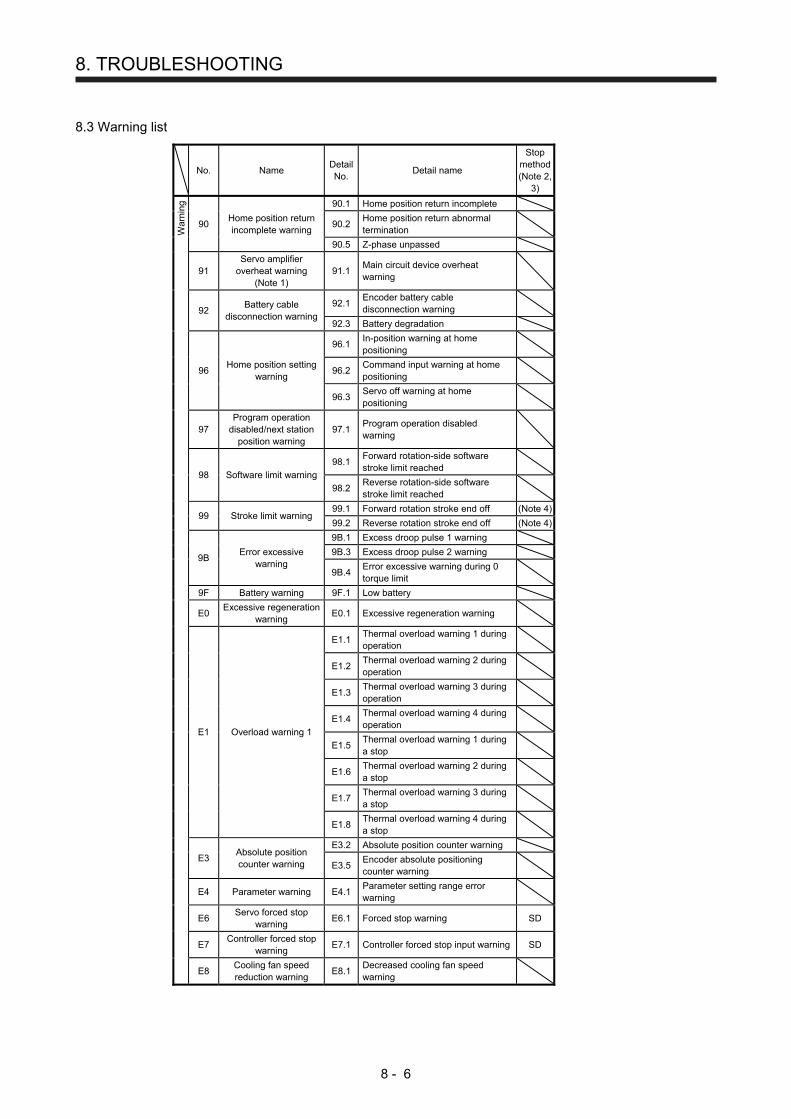
8. TROUBLESHOOTING
8 - 6
8.3 Warning list
No. Name Detail No.
Detail name
Stop method(Note 2,
3)
W
arni
ng
90.1 Home position return incomplete
90 Home position return incomplete warning
90.2 Home position return abnormal termination
90.5 Z-phase unpassed
91 Servo amplifier
overheat warning (Note 1)
91.1 Main circuit device overheat warning
92
Battery cable disconnection warning
92.1 Encoder battery cable disconnection warning
92.3 Battery degradation
96 Home position setting
warning
96.1 In-position warning at home positioning
96.2 Command input warning at home positioning
96.3 Servo off warning at home positioning
97 Program operation
disabled/next station position warning
97.1 Program operation disabled warning
98 Software limit warning
98.1 Forward rotation-side software stroke limit reached
98.2 Reverse rotation-side software stroke limit reached
99 Stroke limit warning
99.1 Forward rotation stroke end off (Note 4)
99.2 Reverse rotation stroke end off (Note 4)
9B Error excessive
warning
9B.1 Excess droop pulse 1 warning
9B.3 Excess droop pulse 2 warning
9B.4 Error excessive warning during 0 torque limit
9F Battery warning 9F.1 Low battery
E0
Excessive regeneration warning
E0.1 Excessive regeneration warning
E1 Overload warning 1
E1.1 Thermal overload warning 1 during operation
E1.2 Thermal overload warning 2 during operation
E1.3 Thermal overload warning 3 during operation
E1.4 Thermal overload warning 4 during operation
E1.5 Thermal overload warning 1 during a stop
E1.6 Thermal overload warning 2 during a stop
E1.7 Thermal overload warning 3 during a stop
E1.8 Thermal overload warning 4 during a stop
E3 Absolute position counter warning
E3.2 Absolute position counter warning
E3.5 Encoder absolute positioning counter warning
E4 Parameter warning E4.1 Parameter setting range error warning
E6 Servo forced stop
warning E6.1 Forced stop warning SD
E7 Controller forced stop
warning E7.1 Controller forced stop input warning SD
E8 Cooling fan speed reduction warning
E8.1 Decreased cooling fan speed warning
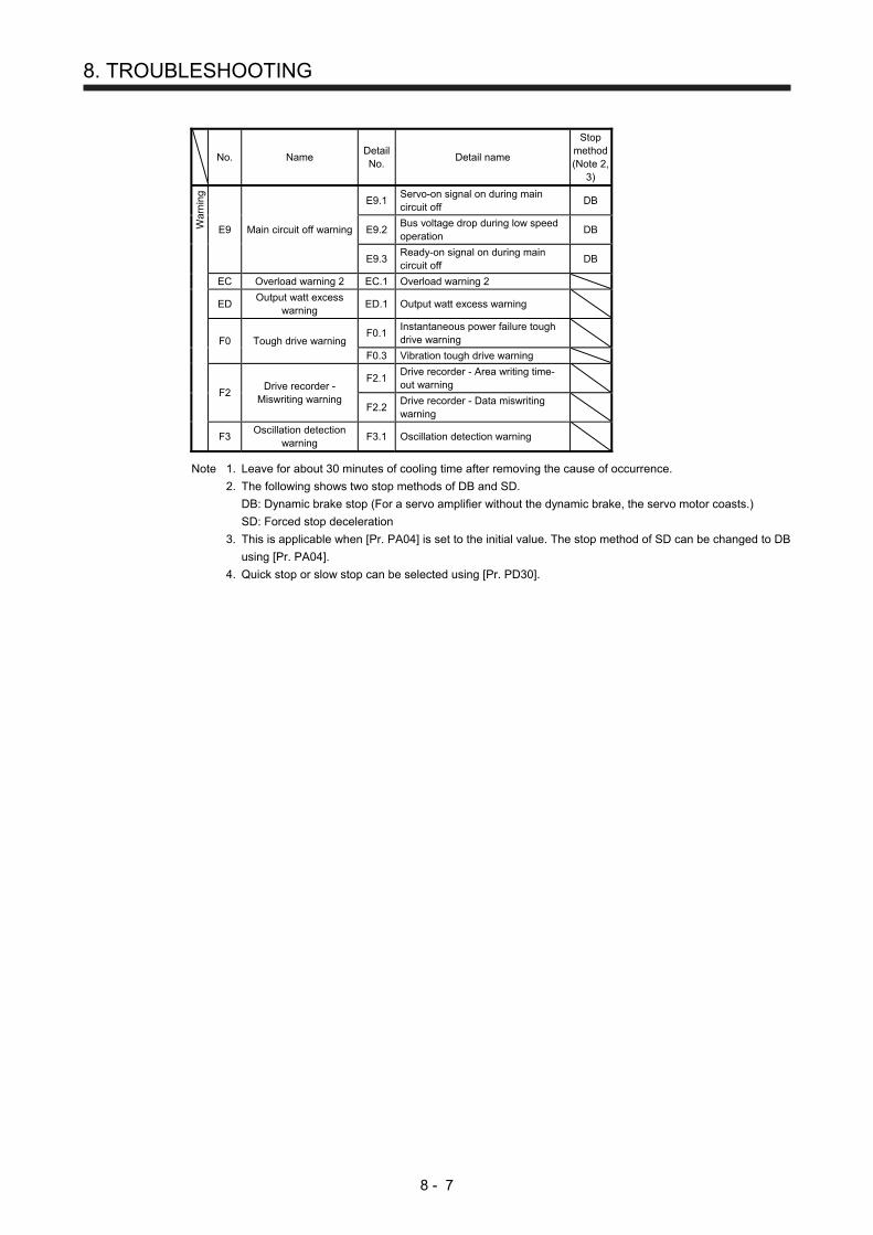
8. TROUBLESHOOTING
8 - 7
No. Name Detail No.
Detail name
Stop method(Note 2,
3)
War
ning
E9 Main circuit off warning
E9.1 Servo-on signal on during main circuit off
DB
E9.2 Bus voltage drop during low speed operation
DB
E9.3 Ready-on signal on during main circuit off
DB
EC Overload warning 2 EC.1 Overload warning 2
ED Output watt excess
warning ED.1 Output watt excess warning
F0 Tough drive warning F0.1
Instantaneous power failure tough drive warning
F0.3 Vibration tough drive warning
F2 Drive recorder -
Miswriting warning
F2.1 Drive recorder - Area writing time-out warning
F2.2 Drive recorder - Data miswriting warning
F3 Oscillation detection
warning F3.1 Oscillation detection warning
Note 1. Leave for about 30 minutes of cooling time after removing the cause of occurrence.
2. The following shows two stop methods of DB and SD.
DB: Dynamic brake stop (For a servo amplifier without the dynamic brake, the servo motor coasts.)
SD: Forced stop deceleration
3. This is applicable when [Pr. PA04] is set to the initial value. The stop method of SD can be changed to DB
using [Pr. PA04].
4. Quick stop or slow stop can be selected using [Pr. PD30].

8. TROUBLESHOOTING
8 - 8
MEMO

9. DIMENSIONS
9 - 1
9. DIMENSIONS
9.1 Servo amplifier
(1) MR-JE-10A to MR-JE-40A
[Unit: mm]
Approx. 80 135
50
168
6
615
66
6
2.9
φ6 mounting hole
The built-in regenerativeresistor (lead wire) is mountedonly in MR-JE-40A.
6
PECNP1
CN1
CN2
CN3
Mass: 0.8 [kg]
L2
L3
P+
C
U
V
W
L1
PE
Terminal
CNP1
Screw size: M4Tightening torque: 1.2 [N•m]
Mounting screw Screw size: M5 Tightening torque: 3.24 [N•m]
Approx. 6
Approx. 50
156
± 0.
5A
ppro
x. 6
App
rox.
6
App
rox.
168
2-M5 screw
Mounting hole process drawing

9. DIMENSIONS
9 - 2
(2) MR-JE-70A/MR-JE-100A
[Unit: mm]
70
Approx. 80 185
3.3
168
4222
22
156
66
φ6 mounting hole
6
PECNP1
CN1
CN2
CN3
Mass: 1.5 [kg]
L2
L3
P+
C
U
V
W
L1
PE
Terminal
CNP1
Screw size: M4Tightening torque: 1.2 [N•m]
Mounting screw Screw size: M5 Tightening torque: 3.24 [N•m]
Ap
pro
x.6
App
rox.
6
App
rox.
168
156
± 0.
5
Approx. 70
42 ± 0.3
Approx. 22 Approx. 6
3-M5 screw
Mounting hole process drawing

9. DIMENSIONS
9 - 3
(3) MR-JE-200A/MR-JE-300A
[Unit: mm]
6
6
6 7816
8
615
6
45
90
85Approx. 80 195
161
6
CNP1
φ6 mounting hole
CNP2
PE Cooling fanair intake
Exhaust
CN1
CN2
CN3Lock knob
Mass: 2.1 [kg]
L2
L3
N-
C
D
P+
U
V
W
L1
CNP2
Terminal
CNP1
Screw size: M4Tightening torque: 1.2 [N•m]
PE
Mounting screw Screw size: M5 Tightening torque: 3.24 [N•m]
Approx. 90
78 ± 0.3Approx. 6 Approx. 6
App
rox.
168
156
± 0.
5A
ppro
x. 6
App
rox.
6
Mounting hole process drawing
3-M5 screw
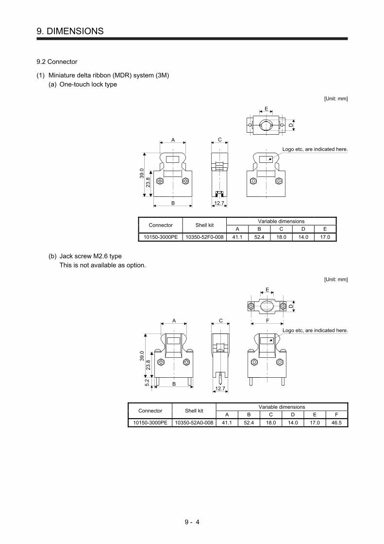
9. DIMENSIONS
9 - 4
9.2 Connector
(1) Miniature delta ribbon (MDR) system (3M)
(a) One-touch lock type
[Unit: mm]
E
B
A
23.8
39.0
12.7
C
Logo etc, are indicated here.
D
Connector Shell kit Variable dimensions
A B C D E
10150-3000PE 10350-52F0-008 41.1 52.4 18.0 14.0 17.0
(b) Jack screw M2.6 type
This is not available as option.
[Unit: mm]
E
B
A
23.8
39.0
12.7
C
Logo etc, are indicated here.
5.2
F
D
Connector Shell kit Variable dimensions
A B C D E F
10150-3000PE 10350-52A0-008 41.1 52.4 18.0 14.0 17.0 46.5
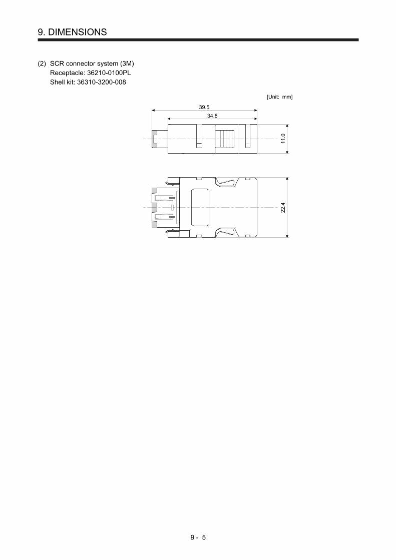
9. DIMENSIONS
9 - 5
(2) SCR connector system (3M)
Receptacle: 36210-0100PL
Shell kit: 36310-3200-008
[Unit: mm]
34.8
39.5
22.4
11.0

9. DIMENSIONS
9 - 6
MEMO
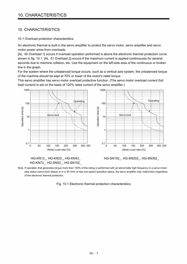
10. CHARACTERISTICS
10 - 1
10. CHARACTERISTICS
10.1 Overload protection characteristics
An electronic thermal is built in the servo amplifier to protect the servo motor, servo amplifier and servo
motor power wires from overloads.
[AL. 50 Overload 1] occurs if overload operation performed is above the electronic thermal protection curve
shown in fig. 10.1. [AL. 51 Overload 2] occurs if the maximum current is applied continuously for several
seconds due to machine collision, etc. Use the equipment on the left-side area of the continuous or broken
line in the graph.
For the system where the unbalanced torque occurs, such as a vertical axis system, the unbalanced torque
of the machine should be kept at 70% or lower of the motor's rated torque.
This servo amplifier has servo motor overload protective function. (The servo motor overload current (full
load current) is set on the basis of 120% rated current of the servo amplifier.)
Ope
ratio
n tim
e [s
]
1000
100
10
1
0.1100 200 3000
Servo-lock
Operating
50 150 250
(Note) Load ratio [%]
320
1000
100
10
1
0.1100 200 3000 50 150 250 320
Ope
ratio
n tim
e [s
]
Servo-lock
Operating
(Note) Load ratio [%]
HG-KN13_, HG-KN23_, HG-KN43_
HG-KN73_, HG-SN52_, HG-SN102_
HG-SN152_, HG-SN202_, HG-SN302_
Note. If operation that generates torque more than 100% of the rating is performed with an abnormally high frequency in a servo motor
stop status (servo-lock status) or in a 30 r/min or less low-speed operation status, the servo amplifier may malfunction regardless
of the electronic thermal protection.
Fig. 10.1 Electronic thermal protection characteristics
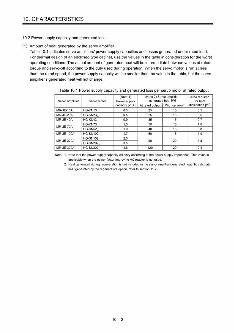
10. CHARACTERISTICS
10 - 2
10.2 Power supply capacity and generated loss
(1) Amount of heat generated by the servo amplifier
Table 10.1 indicates servo amplifiers' power supply capacities and losses generated under rated load.
For thermal design of an enclosed type cabinet, use the values in the table in consideration for the worst
operating conditions. The actual amount of generated heat will be intermediate between values at rated
torque and servo-off according to the duty used during operation. When the servo motor is run at less
than the rated speed, the power supply capacity will be smaller than the value in the table, but the servo
amplifier's generated heat will not change.
Table 10.1 Power supply capacity and generated loss per servo motor at rated output
Servo amplifier Servo motor (Note 1)
Power supply capacity [kVA]
(Note 2) Servo amplifier-generated heat [W]
Area required for heat
dissipation [m2] At rated output With servo-off
MR-JE-10A HG-KN13_ 0.3 25 15 0.5
MR-JE-20A HG-KN23_ 0.5 25 15 0.5
MR-JE-40A HG-KN43_ 0.9 35 15 0.7
MR-JE-70A HG-KN73_ 1.3 50 15 1.0
HG-SN52_ 1.0 40 15 0.8
MR-JE-100A HG-SN102_ 1.7 50 15 1.0
MR-JE-200A HG-SN152_ 2.5
90 20 1.8 HG-SN202_ 3.5
MR-JE-300A HG-SN302_ 4.8 120 20 2.4
Note 1. Note that the power supply capacity will vary according to the power supply impedance. This value is
applicable when the power factor improving AC reactor is not used.
2. Heat generated during regeneration is not included in the servo amplifier-generated heat. To calculate
heat generated by the regenerative option, refer to section 11.2.

10. CHARACTERISTICS
10 - 3
(2) Heat dissipation area for an enclosed type cabinet
The enclosed type cabinet (hereafter called the cabinet) which will contain the servo amplifier should be
designed to ensure that its temperature rise is within +10 ˚C at the ambient temperature of 40 ˚C.
Calculate the necessary cabinet dissipation area (allowing a margin of approximately 5 °C for the
ambient temperature of 55 °C maximum) with equation (10.1).
A = K • ΔT
P ················································································································· (10.1)
A
P
∆T
K
: Heat dissipation area [m2]
: Loss generated in the cabinet [W]
: Difference between internal and ambient temperatures [˚C]
: Heat dissipation coefficient [5 to 6]
When calculating the heat dissipation area with equation 10.1, assume that P is the sum of all losses
generated in the cabinet. Refer to table 10.1 for heat generated by the servo amplifier. "A" indicates the
effective area for heat dissipation, but if the cabinet is directly installed on an insulated wall, that extra
amount must be added to the cabinet's surface area. The required heat dissipation area will vary with
the conditions in the cabinet. If convection in the cabinet is poor and heat builds up, effective heat
dissipation will not be possible. Therefore, arrangement of the equipment in the cabinet and the use of a
cooling fan should be considered. Table 10.1 lists the cabinet dissipation area for each servo amplifier
(guideline) when the servo amplifier is operated at the ambient temperature of 40 ˚C under rated load.
Fig. 10.2 Temperature distribution in an enclosed type cabinet
When air flows along the outer wall of the cabinet, effective heat exchange will be possible, because the
temperature slope inside and outside the cabinet will be steeper.

10. CHARACTERISTICS
10 - 4
10.3 Dynamic brake characteristics
POINT
Do not use dynamic brake to stop in a normal operation as it is the function to
stop in emergency.
For a machine operating at the recommended load to motor inertia ratio or less,
the estimated number of usage times of the dynamic brake is 1000 times while
the machine decelerates from the rated speed to a stop once in 10 minutes.
Be sure to enable EM1 (Forced stop 1) after servo motor stops when using EM1
(Forced stop 1) frequently in other than emergency.
The coasting distance of HG-KN series and HG-SN series servo motors may be
different from that of HF-KN series and HF-SN series.
10.3.1 Dynamic brake operation
(1) Calculation of coasting distance
Fig. 10.3 shows the pattern in which the servo motor comes to a stop when the dynamic brake is
operated. Use equation 10.2 to calculate an approximate coasting distance to a stop. The dynamic
brake time constant τ varies with the servo motor and machine operation speeds. (Refer to (2) of this
section.)
A working part generally has a friction force. Therefore, actual coasting distance will be shorter than a
maximum coasting distance calculated with the following equation.
V0
OFF
ON
Machine speed
teTime
EM1 (Forced stop 1)
Dynamic braketime constant τ
Fig. 10.3 Dynamic brake operation diagram
Lmax = 60V0 •
JM
te + 1 + JL ··························································································· (10.2)
Lmax: Maximum coasting distance ······················································································ [mm]
V0: Machine's fast feed speed ····················································································· [mm/min]
JM: Moment of inertia of the servo motor ································································· [× 10-4 kg•m2]
JL: Load moment of inertia converted into equivalent value on servo motor shaft ·············· [× 10-4 kg•m2]
τ: Dynamic brake time constant ···························································································· [s]
te: Delay time of control section ···························································································· [s]
There is internal relay delay time of about 10 ms.
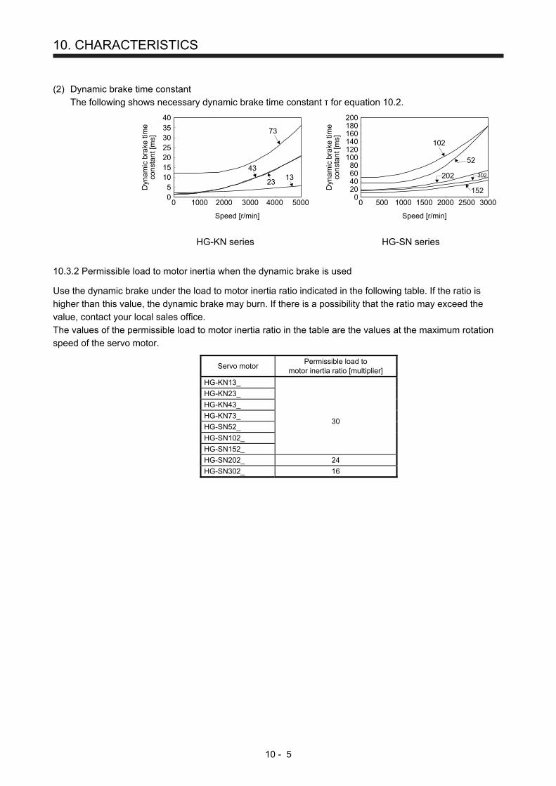
10. CHARACTERISTICS
10 - 5
(2) Dynamic brake time constant
The following shows necessary dynamic brake time constant τ for equation 10.2.
0
2025
15105
303540
0 1000 2000 3000 4000 5000
73
1343
23
Dyn
amic
bra
ke ti
me
cons
tant
[ms]
Speed [r/min]
0
40
120100
8060
20
140160180200
0 500 1000 1500 2000 2500 3000
102
52
202 302
152
Speed [r/min]
Dyn
amic
bra
ke ti
me
cons
tant
[ms]
HG-KN series HG-SN series
10.3.2 Permissible load to motor inertia when the dynamic brake is used
Use the dynamic brake under the load to motor inertia ratio indicated in the following table. If the ratio is
higher than this value, the dynamic brake may burn. If there is a possibility that the ratio may exceed the
value, contact your local sales office.
The values of the permissible load to motor inertia ratio in the table are the values at the maximum rotation
speed of the servo motor.
Servo motor Permissible load to
motor inertia ratio [multiplier]
HG-KN13_
HG-KN23_
HG-KN43_
HG-KN73_ 30
HG-SN52_
HG-SN102_
HG-SN152_
HG-SN202_ 24
HG-SN302_ 16

10. CHARACTERISTICS
10 - 6
10.4 Cable bending life
The bending life of the cables is shown below. This graph calculated values. Since they are not guaranteed
values, provide a little allowance for these values.
a:
b: Standard encoder cableStandard motor power cableStandard electromagnetic brake cable
Long bending life encoder cableLong bending life motor power cableLong bending life electromagnetic brake cable
Num
ber
of b
endi
ng ti
mes
1 × 10⁸
5 × 10⁷
1 × 10⁷
5 × 10⁶
1 × 10⁶
5 × 10⁵
1 × 10⁵
5 × 10⁴
1 × 10⁴
5 × 10³
1 × 10³
4 7 10 20 40 70 100 200
Bend radius [mm]
a
b
10.5 Inrush current at power-on
POINT
The inrush current values can change depending on frequency of turning on/off
the power and ambient temperature.
The following table indicates the inrush currents (reference data) that will flow when 240 V AC is applied at
the power supply capacity of 2500 kVA and the wiring length of 1 m. Even when you use a 1-phase 200 V
AC power supply with MR-JE-10A to MR-JE-200A, the inrush currents will be the same.
Servo amplifier Inrush currents (A0-P)
MR-JE-10A, MR-JE-20A, MR-JE-40A
32 A (attenuated to approx. 3 A in 20 ms)
MR-JE-70A, MR-JE-100A 36 A
(attenuated to approx. 7 A in 20 ms)
MR-JE-200A, MR-JE-300A 102 A
(attenuated to approx. 12 A in 20 ms)
Since large inrush currents flow in the power supplies, always use molded-case circuit breakers and
magnetic contactors. (Refer to section 11.6.)
When circuit protectors are used, it is recommended that the inertia delay type, which is not tripped by an
inrush current, be used.
11. OPTIONS AND PERIPHERAL EQUIPMENT
11 - 1
11. OPTIONS AND PERIPHERAL EQUIPMENT
WARNING
Before connecting options and peripheral equipment, turn off the power and wait
for 15 minutes or more until the charge lamp turns off. Otherwise, an electric
shock may occur. In addition, when confirming whether the charge lamp is off or
not, always confirm it from the front of the servo amplifier.
CAUTION Use the specified peripheral equipment and options to prevent a malfunction or a
fire.
POINT
We recommend using HIV wires to wire the servo amplifiers, options, and
peripheral equipment. Therefore, the recommended wire sizes may differ from
those used for the previous servo amplifiers.
11.1 Cable/connector sets
POINT
The IP rating indicated for cables and connectors is their protection against
ingress of dust and raindrops when they are connected to a servo amplifier or
servo motor. If the IP rating of the cable, connector, servo amplifier and servo
motor vary, the overall IP rating depends on the lowest IP rating of all
components.
Please purchase the cable and connector options indicated in this section.

11. OPTIONS AND PERIPHERAL EQUIPMENT
11 - 2
11.1.1 Combinations of cable/connector sets
Refer to "HG-KN/HG-SN Servo Motor Instruction Manual" for options forservo motor power supply, electromagnetic brake, and encoder.
(Note)
Personal computer
5)
1) (Packed with theservo amplifier)
To 24 V DC power supplyfor electromagnetic brake Servo motor
Encoderconnector
Servo amplifier
Operationpanel
Controller
3)
2)
4)
CN3
CN1
CN2
Powerconnector
Brakeconnector
CNP1
Note. Connectors for 1 kW or less. Refer to section 3.3.3 (1) (b) for 2 kW or more.
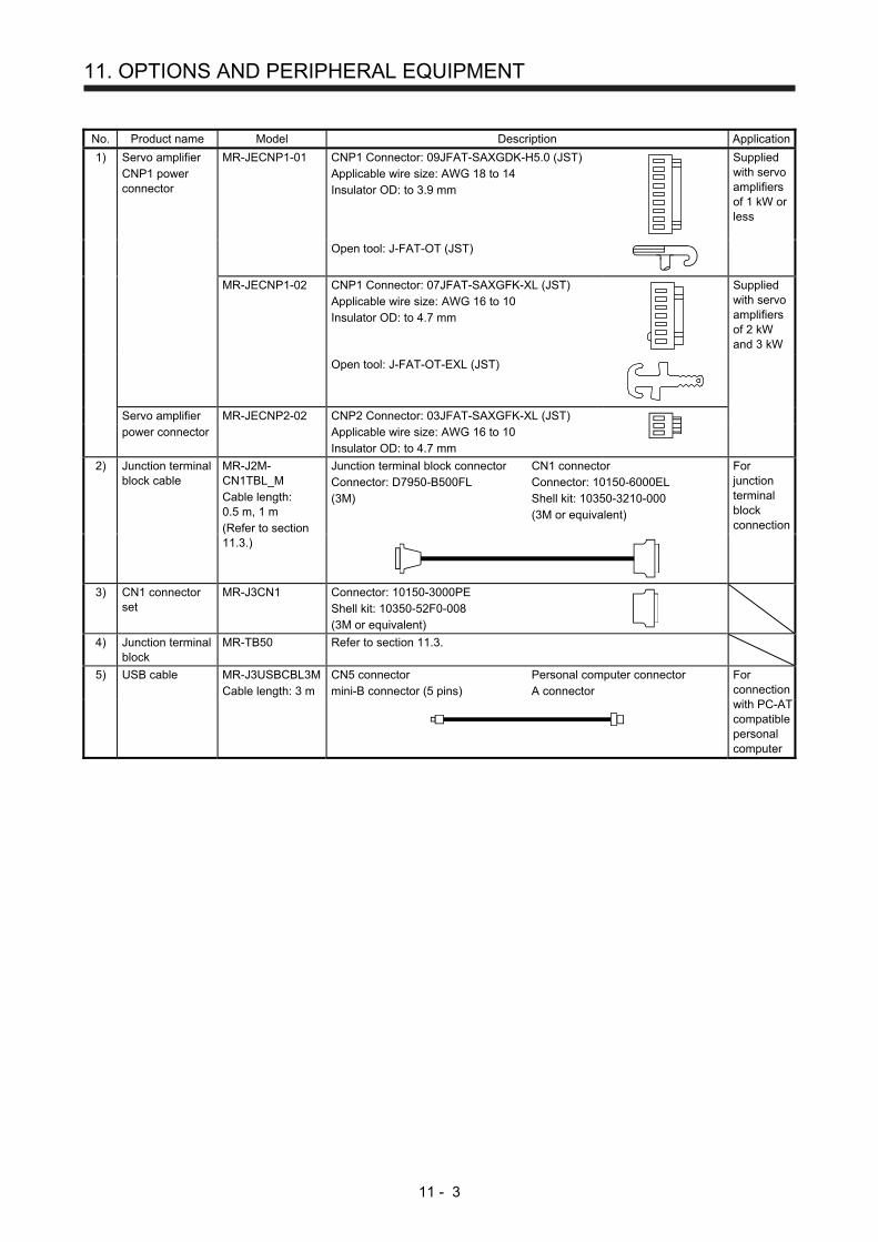
11. OPTIONS AND PERIPHERAL EQUIPMENT
11 - 3
No. Product name Model Description Application
1) Servo amplifier CNP1 power connector
MR-JECNP1-01 CNP1 Connector: 09JFAT-SAXGDK-H5.0 (JST) Applicable wire size: AWG 18 to 14 Insulator OD: to 3.9 mm
Supplied with servo amplifiers of 1 kW or less
Open tool: J-FAT-OT (JST)
MR-JECNP1-02 CNP1 Connector: 07JFAT-SAXGFK-XL (JST) Applicable wire size: AWG 16 to 10 Insulator OD: to 4.7 mm
Supplied with servo amplifiers of 2 kW and 3 kW
Open tool: J-FAT-OT-EXL (JST)
Servo amplifier power connector
MR-JECNP2-02 CNP2 Connector: 03JFAT-SAXGFK-XL (JST) Applicable wire size: AWG 16 to 10 Insulator OD: to 4.7 mm
2) Junction terminal block cable
MR-J2M-CN1TBL_M Cable length: 0.5 m, 1 m (Refer to section 11.3.)
Junction terminal block connector Connector: D7950-B500FL (3M)
CN1 connector Connector: 10150-6000EL Shell kit: 10350-3210-000 (3M or equivalent)
For junction terminal block connection
3) CN1 connector set
MR-J3CN1 Connector: 10150-3000PE Shell kit: 10350-52F0-008 (3M or equivalent)
4) Junction terminal block
MR-TB50 Refer to section 11.3.
5) USB cable MR-J3USBCBL3M Cable length: 3 m
CN5 connector mini-B connector (5 pins)
Personal computer connector A connector
For connection with PC-AT compatible personal computer
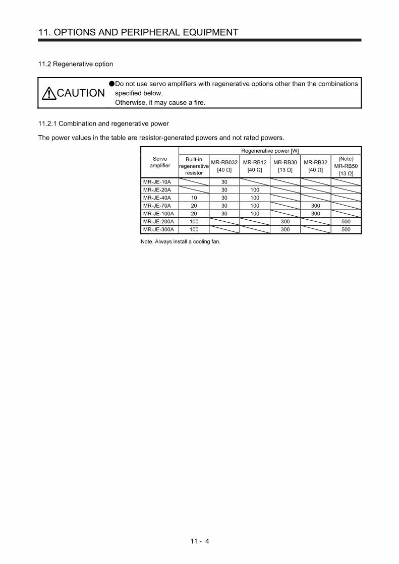
11. OPTIONS AND PERIPHERAL EQUIPMENT
11 - 4
11.2 Regenerative option
CAUTION Do not use servo amplifiers with regenerative options other than the combinations
specified below.
Otherwise, it may cause a fire.
11.2.1 Combination and regenerative power
The power values in the table are resistor-generated powers and not rated powers.
Servo amplifier
Regenerative power [W]
Built-in regenerative
resistor
MR-RB032[40 Ω]
MR-RB12 [40 Ω]
MR-RB30 [13 Ω]
MR-RB32 [40 Ω]
(Note) MR-RB50
[13 Ω]
MR-JE-10A 30
MR-JE-20A 30 100
MR-JE-40A 10 30 100
MR-JE-70A 20 30 100 300
MR-JE-100A 20 30 100 300
MR-JE-200A 100 300 500
MR-JE-300A 100 300 500
Note. Always install a cooling fan.
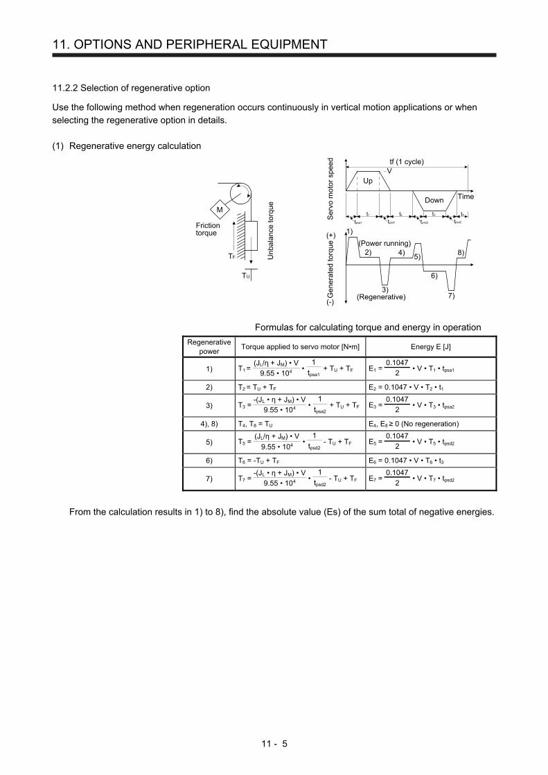
11. OPTIONS AND PERIPHERAL EQUIPMENT
11 - 5
11.2.2 Selection of regenerative option
Use the following method when regeneration occurs continuously in vertical motion applications or when
selecting the regenerative option in details.
(1) Regenerative energy calculation
M
Frictiontorque
Unb
alan
ce to
rque
TF
TU
Ser
vo m
otor
spe
edG
ener
ated
torq
ue
Time
UpVtf (1 cycle)
Down
(+)
(-)
(Power running)
(Regenerative)
tpsd2
t2 t3 t4t1
tpsa2tpsd1tpsa1
1)
2)
3)
4)5)
6)
7)
8)
Formulas for calculating torque and energy in operation
Regenerative power
Torque applied to servo motor [N•m] Energy E [J]
1) T1 = 9.55 • 104
(JL/η + JM) • V •
tpsa1
1 + TU + TF E1 =
2
0.1047 • V • T1 • tpsa1
2) T2 = TU + TF E2 = 0.1047 • V • T2 • t1
3) T3 = 9.55 • 104
-(JL • η + JM) • V •
tpsa2
1 + TU + TF E3 =
2
0.1047 • V • T3 • tpsa2
4), 8) T4, T8 = TU E4, E8 ≥ 0 (No regeneration)
5) T5 = 9.55 • 104
(JL/η + JM) • V •
tpsd2
1 - TU + TF E5 =
2
0.1047 • V • T5 • tpsd2
6) T6 = -TU + TF E6 = 0.1047 • V • T6 • t3
7) T7 = 9.55 • 104
-(JL • η + JM) • V •
tpsd2
1 - TU + TF E7 =
2
0.1047 • V • T7 • tpsd2
From the calculation results in 1) to 8), find the absolute value (Es) of the sum total of negative energies.
11. OPTIONS AND PERIPHERAL EQUIPMENT
11 - 6
(2) Losses of servo motor and servo amplifier in regenerative mode
The following table lists the efficiencies and other data of the servo motor and servo amplifier in the
regenerative mode.
Servo amplifier Inverse
efficiency [%] Capacitor
charging [J] Servo amplifier
Inverse efficiency [%]
Capacitor charging [J]
MR-JE-10A 55 11 MR-JE-100A 85 25
MR-JE-20A 75 11 MR-JE-200A 85 42
MR-JE-40A 85 14 MR-JE-300A 85 42
MR-JE-70A 85 25
Inverse efficiency (η): Efficiency including some efficiencies of the servo motor and servo amplifier
when rated (regenerative) torque is generated at rated speed. Since the
efficiency varies with the speed and generated torque, allow for about 10%.
Capacitor charging (Ec): Energy charged into the electrolytic capacitor in the servo amplifier
Subtract the capacitor charging from the result of multiplying the sum total of regenerative energies
by the inverse efficiency to calculate the energy consumed by the regenerative option.
ER [J] = η • Es - Ec
Select a necessary regenerative option by calculating the power consumption of the regenerative
option on the basis of one-cycle operation period tf [s].
PR [W] = ER/tf
11.2.3 Parameter setting
Set [Pr. PA02] according to the option to be used.
Regenerative option selection00: Regenerative option is not used.
For servo amplifier of 200 W or less, regenerative resistor is not used.For servo amplifier of 0.4 kW to 3 kW, built-in regenerative resistor is used.
02: MR-RB03203: MR-RB1204: MR-RB3205: MR-RB3006: MR-RB50 (Cooling fan is required)
0 0
[Pr. PA02]

11. OPTIONS AND PERIPHERAL EQUIPMENT
11 - 7
11.2.4 Selection of regenerative option
POINT
When you use a regenerative option with an MR-JE-40A to MR-JE-100A,
remove the built-in regenerative resistor and wiring from the servo amplifier.
When MR-RB50 is used, a cooling fan is required to cool it. The cooling fan
should be prepared by the customer.
For the wire sizes used for wiring, refer to section 11.5.
A built-in regenerative resistor should not be mounted/removed frequently.
When you remount a built-in regenerative resistor, check the lead wires of the
built-in regenerative resistor for scratches or cracks.
The regenerative option generates heat of 100 ˚C higher than the ambient temperature. Fully consider heat
dissipation, installation position, wires used, etc. before installing the option. For wiring, use flame-resistant
wires or make the wires flame-resistant and keep them away from the regenerative option. Always use
twisted cables of max. 5 m length for connection with the servo amplifier.

11. OPTIONS AND PERIPHERAL EQUIPMENT
11 - 8
(1) MR-JE-100A or less
When you use a regenerative option for MR-JE-40A to MR-JE-100A, remove wirings of P+ and C,
remove the built-in regenerative resistor, and then connect the regenerative option between P+ and C.
G3 and G4 are terminals for thermal sensor. Between G3 and G4 is opened when the regenerative
option overheats abnormally.
Always remove the wiring (across P+ to C) of theservo amplifier built-in regenerative resistor.
P+
C
G4
G3
C
P
Regenerative option
5 m or less
Servo amplifier
(Note 2)
(Note 1)
Cooling fan
(Note 3)
Note 1. The built-in regenerative resistor is not provided for MR-JE-10A and MR-JE-20A.
2. Make up a sequence which will switch off the magnetic contactor when abnormal
heating occurs.
G3-G4 contact specifications
Maximum voltage: 120 V AC/DC
Maximum current: 0.5 A/4.8 V DC
Maximum capacity: 2.4 VA
3. When the ambient temperature is more than 55 °C and the regenerative load ratio
is more than 60% in MR-RB32, forcefully cool the air with a cooling fan (1.0
m3/min or more, 92 mm × 92 mm). A cooling fan is not required if the ambient
temperature is 35 °C or less. (A cooling fan is required for the shaded area in the
following graph.)
100
60
00
Ambient temperature [°C]
35 55
A cooling fan isnot required.
A cooling fan is required.
Load
rat
io [%
]
11. OPTIONS AND PERIPHERAL EQUIPMENT
11 - 9
To remove the built-in regenerative resistor mounted on the back of MR-JE-40A to MR-JE-100A, follow
the procedures 1) to 3) with referring the illustration.
1) Disconnect the wirings of the built-in regenerative resistor from the power connector (CNP1).
(Refer to (3) (b) of 3.3.2.)
2) Remove the wirings of the built-in regenerative resistor from the closest position to the power
connector (CNP1) in order. Please pay full attention not to break the wirings.
3) Remove the screw fixing the built-in regenerative resistor and dismount the built-in regenerative
resistor.
(Note)3)
1)
2)
Note. Screw size: M3
Tightening torque: 0.72 [N•m]
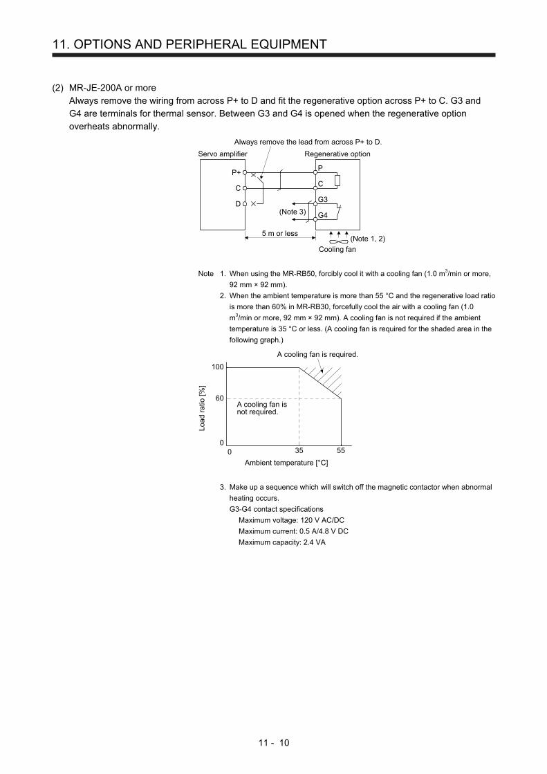
11. OPTIONS AND PERIPHERAL EQUIPMENT
11 - 10
(2) MR-JE-200A or more
Always remove the wiring from across P+ to D and fit the regenerative option across P+ to C. G3 and
G4 are terminals for thermal sensor. Between G3 and G4 is opened when the regenerative option
overheats abnormally.
D
P+
C
G4
G3
C
P
Regenerative option
5 m or less
Servo amplifier
Always remove the lead from across P+ to D.
(Note 3)
Cooling fan
(Note 1, 2)
Note 1. When using the MR-RB50, forcibly cool it with a cooling fan (1.0 m3/min or more,
92 mm × 92 mm).
2. When the ambient temperature is more than 55 °C and the regenerative load ratio
is more than 60% in MR-RB30, forcefully cool the air with a cooling fan (1.0
m3/min or more, 92 mm × 92 mm). A cooling fan is not required if the ambient
temperature is 35 °C or less. (A cooling fan is required for the shaded area in the
following graph.)
100
60
00
Ambient temperature [°C]
35 55
A cooling fan isnot required.
A cooling fan is required.
Load
rat
io [%
]
3. Make up a sequence which will switch off the magnetic contactor when abnormal
heating occurs.
G3-G4 contact specifications
Maximum voltage: 120 V AC/DC
Maximum current: 0.5 A/4.8 V DC
Maximum capacity: 2.4 VA

11. OPTIONS AND PERIPHERAL EQUIPMENT
11 - 11
11.2.5 Dimensions
(1) MR-RB12
[Unit: mm]
5
144
Approx. 20
169
168
156
6 12
6
36
40φ6 mounting hole
TE1
15
App
rox.
6
1492
TE1 terminal block
G3
G4
P
C
Applicable wire size: 0.2 mm2 to 2.5 mm2 (AWG 24 to 12) Tightening torque: 0.5 to 0.6 [N•m]
Mounting screw Screw size: M5 Tightening torque: 3.24 [N•m]
Mass: 1.1 [kg]
(2) MR-RB30/MR-RB32
[Unit: mm]
8.5
125
150
App
rox.
30
142
7982
.530
8.5
10 90101.5 82.5
31817
335
Air intake
7
100
Cooling fan mountingscrew (2-M4 screw)
Terminal block
P
C
G3
G4
Terminal screw size: M4 Tightening torque: 1.2 [N•m]
Mounting screw Screw size: M6 Tightening torque: 5.4 [N•m]
Mass: 2.9 [kg]

11. OPTIONS AND PERIPHERAL EQUIPMENT
11 - 12
(3) MR-RB50
[Unit: mm]
2.3
133
82.5
49 82.5
Cooling fan mountingscrew (2-M3 screw)On opposite side
200 17217 8120
1081212.5
162.
5
350
162.
512
.5
7Approx. 30
7 × 14slotted hole
Airintake
Terminal block
P
C
G3
G4
Terminal screw size: M4 Tightening torque: 1.2 [N•m]
Mounting screw Screw size: M6 Tightening torque: 5.4 [N•m]
Mass: 5.6 [kg]
(4) MR-RB032
[Unit: mm]
TE1
30
15
99
1.6
119
144
12
156
168
66
5
App
rox.
6
App
rox.
12
Approx. 20
φ6 mounting hole
TE1 terminal block
G3
G4
P
C
Applicable wire size: 0.2 mm2 to 2.5 mm2 (AWG 24 to 12) Tightening torque: 0.5 to 0.6 [N•m]
Mounting screw Screw size: M5 Tightening torque: 3.24 [N•m]
Mass: 0.5 [kg]
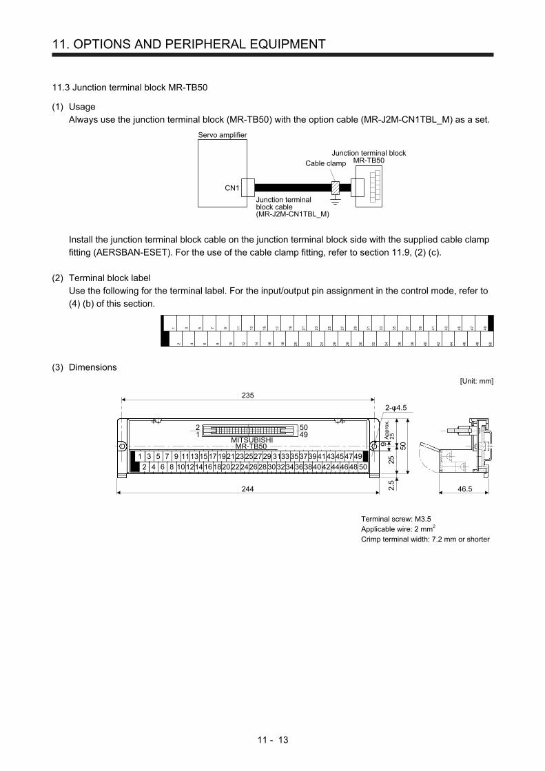
11. OPTIONS AND PERIPHERAL EQUIPMENT
11 - 13
11.3 Junction terminal block MR-TB50
(1) Usage
Always use the junction terminal block (MR-TB50) with the option cable (MR-J2M-CN1TBL_M) as a set.
Servo amplifier
CN1
Junction terminal blockMR-TB50
Junction terminalblock cable(MR-J2M-CN1TBL_M)
Cable clamp
Install the junction terminal block cable on the junction terminal block side with the supplied cable clamp
fitting (AERSBAN-ESET). For the use of the cable clamp fitting, refer to section 11.9, (2) (c).
(2) Terminal block label
Use the following for the terminal label. For the input/output pin assignment in the control mode, refer to
(4) (b) of this section.
1
2
3
4
56
7
8
9
10
11
12
13
14
15
16
17
18
19
20
21
22
23
24
25
26
27
28
29
30
31
32
33
34
35
36
37
38
39
40
41
42
43
44
45
46
47
48
49
50
(3) Dimensions
[Unit: mm]
23550
25A
ppro
x.2
5
9
21
5049
MITSUBISHIMR-TB50
4.5
244 2.5
46.5
1 3 5 7 9 11131517192123252729 3133
2 4 6 8 101214161820222426283032
3537394143454749
3436384042444648 50
2-
Terminal screw: M3.5 Applicable wire: 2 mm2 Crimp terminal width: 7.2 mm or shorter

11. OPTIONS AND PERIPHERAL EQUIPMENT
11 - 14
(4) Junction terminal block cable MR-J2M-CN1TBL_M
(a) Model explanations
Model:
05
1
Symbol Cable length [m]
0.5
1
(b) Connection diagram
10150-6000EL (servo amplifier side) D7950-B500FL (junction terminal side)
Position
LGLA
LARLB
LBRLZ
LZRPPPG
OPCSDPSDNSON
RESDICOMDICOM
ZSPINP
MO1TLALG
MO2LG
TRE
OPLGNPNG
RDPRDNCR
EM2LSPLSN
DOCOMDOCOM
ALMRD
SD
Speed
VCLGLA
LARLB
LBRLZ
LZR
SDPSDNSON
ST1DICOMDICOM
ZSPSA
MO1TLALG
MO2LG
TRE
OPLG
RDPRDNST2EM2LSPLSN
DOCOMDOCOM
ALMRD
SD
Torque
VLALGLA
LARLB
LBRLZ
LZR
SDPSDNSON
RS2DICOMDICOM
ZSP
MO1TCLG
MO2LG
TRE
OPLG
RDPRDNRS1EM2
DOCOMDOCOM
ALMRD
SD
1234567891011121314151617181920212223242526272829303132333435363738394041424344454647484950
Plate
123456789
1011121314151617181920212223242526272829303132333435363738394041424344454647484950
Signal symbolPin No. Pin No.
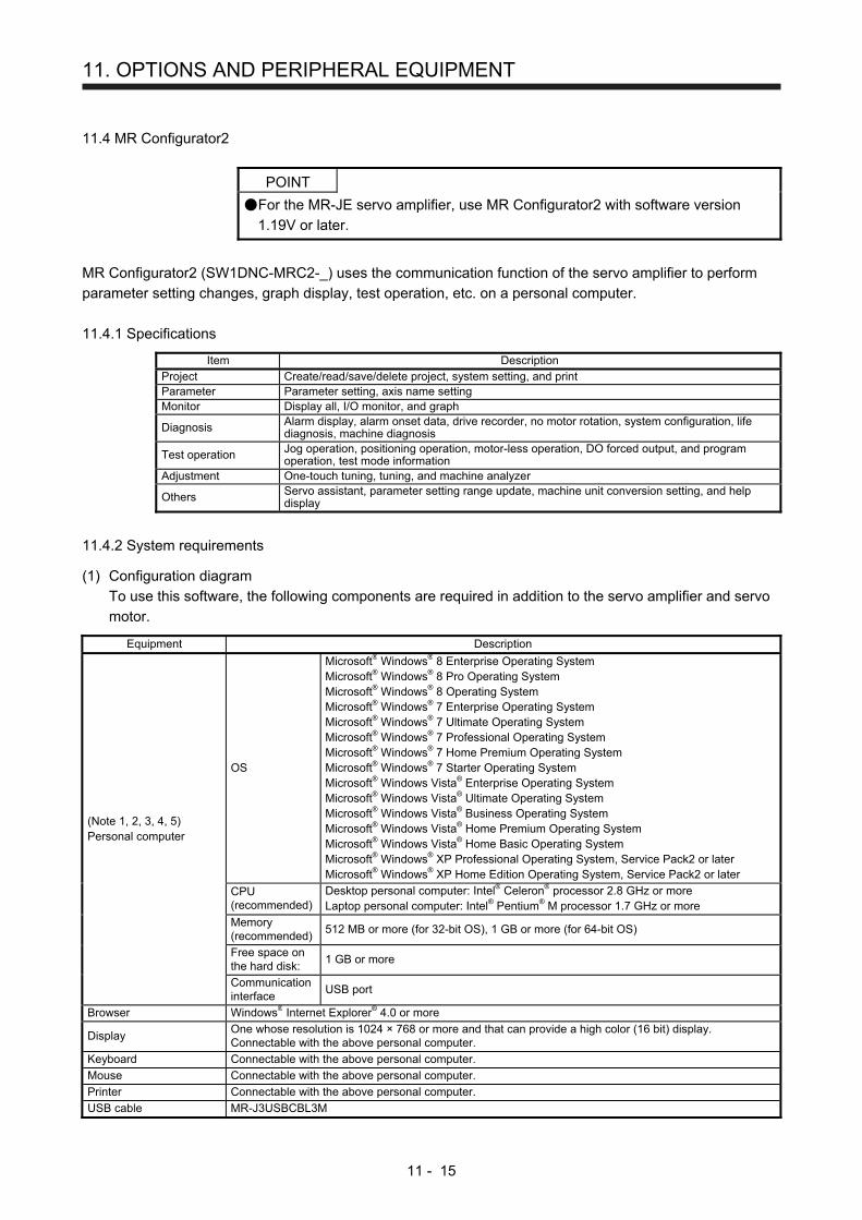
11. OPTIONS AND PERIPHERAL EQUIPMENT
11 - 15
11.4 MR Configurator2
POINT
For the MR-JE servo amplifier, use MR Configurator2 with software version
1.19V or later.
MR Configurator2 (SW1DNC-MRC2-_) uses the communication function of the servo amplifier to perform
parameter setting changes, graph display, test operation, etc. on a personal computer.
11.4.1 Specifications
Item DescriptionProject Create/read/save/delete project, system setting, and printParameter Parameter setting, axis name settingMonitor Display all, I/O monitor, and graph
Diagnosis Alarm display, alarm onset data, drive recorder, no motor rotation, system configuration, life diagnosis, machine diagnosis
Test operation Jog operation, positioning operation, motor-less operation, DO forced output, and program operation, test mode information
Adjustment One-touch tuning, tuning, and machine analyzer
Others Servo assistant, parameter setting range update, machine unit conversion setting, and help display
11.4.2 System requirements
(1) Configuration diagram
To use this software, the following components are required in addition to the servo amplifier and servo
motor.
Equipment Description
(Note 1, 2, 3, 4, 5) Personal computer
OS
Microsoft® Windows® 8 Enterprise Operating System Microsoft® Windows® 8 Pro Operating System Microsoft® Windows® 8 Operating System Microsoft® Windows® 7 Enterprise Operating System Microsoft® Windows® 7 Ultimate Operating System Microsoft® Windows® 7 Professional Operating System Microsoft® Windows® 7 Home Premium Operating System Microsoft® Windows® 7 Starter Operating System Microsoft® Windows Vista® Enterprise Operating System Microsoft® Windows Vista® Ultimate Operating System Microsoft® Windows Vista® Business Operating System Microsoft® Windows Vista® Home Premium Operating System Microsoft® Windows Vista® Home Basic Operating System Microsoft® Windows® XP Professional Operating System, Service Pack2 or later Microsoft® Windows® XP Home Edition Operating System, Service Pack2 or later
CPU (recommended)
Desktop personal computer: Intel® Celeron® processor 2.8 GHz or more Laptop personal computer: Intel® Pentium® M processor 1.7 GHz or more
Memory (recommended)
512 MB or more (for 32-bit OS), 1 GB or more (for 64-bit OS)
Free space on the hard disk:
1 GB or more
Communication interface
USB port
Browser Windows® Internet Explorer® 4.0 or more
Display One whose resolution is 1024 × 768 or more and that can provide a high color (16 bit) display. Connectable with the above personal computer.
Keyboard Connectable with the above personal computer.
Mouse Connectable with the above personal computer.
Printer Connectable with the above personal computer.
USB cable MR-J3USBCBL3M
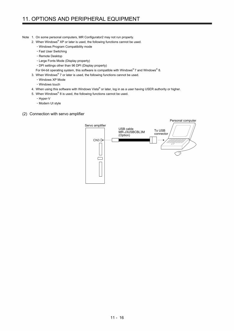
11. OPTIONS AND PERIPHERAL EQUIPMENT
11 - 16
Note 1. On some personal computers, MR Configurator2 may not run properly.
2. When Windows® XP or later is used, the following functions cannot be used.
Windows Program Compatibility mode
Fast User Switching
Remote Desktop
Large Fonts Mode (Display property)
DPI settings other than 96 DPI (Display property)
For 64-bit operating system, this software is compatible with Windows® 7 and Windows® 8.
3. When Windows® 7 or later is used, the following functions cannot be used.
Windows XP Mode
Windows touch
4. When using this software with Windows Vista® or later, log in as a user having USER authority or higher.
5. When Windows® 8 is used, the following functions cannot be used.
Hyper-V
Modern UI style
(2) Connection with servo amplifier
To USBconnector
USB cableMR-J3USBCBL3M(Option)
Personal computer
Servo amplifier
CN3

11. OPTIONS AND PERIPHERAL EQUIPMENT
11 - 17
11.4.3 Precautions for using USB communication function
Note the following to prevent an electric shock and malfunction of the servo amplifier.
(1) Power connection of personal computers
Connect your personal computer with the following procedures.
(a) When you use a personal computer with AC power supply
1) When using a personal computer with a three-core power plug or power plug with grounding wire,
use a three-pin socket or ground the grounding wire.
2) When your personal computer has two-core plug and has no grounding wire, connect the
personal computer to the servo amplifier with the following procedures.
a) Disconnect the power plug of the personal computer from an AC power socket.
b) Check that the power plug was disconnected and connect the device to the servo amplifier.
c) Connect the power plug of the personal computer to the AC power socket.
(b) When you use a personal computer with battery
You can use as it is.
(2) Connection with other devices using servo amplifier communication function
When the servo amplifier is charged with electricity due to connection with a personal computer and the
charged servo amplifier is connected with other devices, the servo amplifier or the connected devices
may malfunction. Connect the servo amplifier and other devices with the following procedures.
(a) Shut off the power of the device for connecting with the servo amplifier.
(b) Shut off the power of the servo amplifier which was connected with the personal computer and
check the charge lamp is off.
(c) Connect the device with the servo amplifier.
(d) Turn on the power of the servo amplifier and the device.
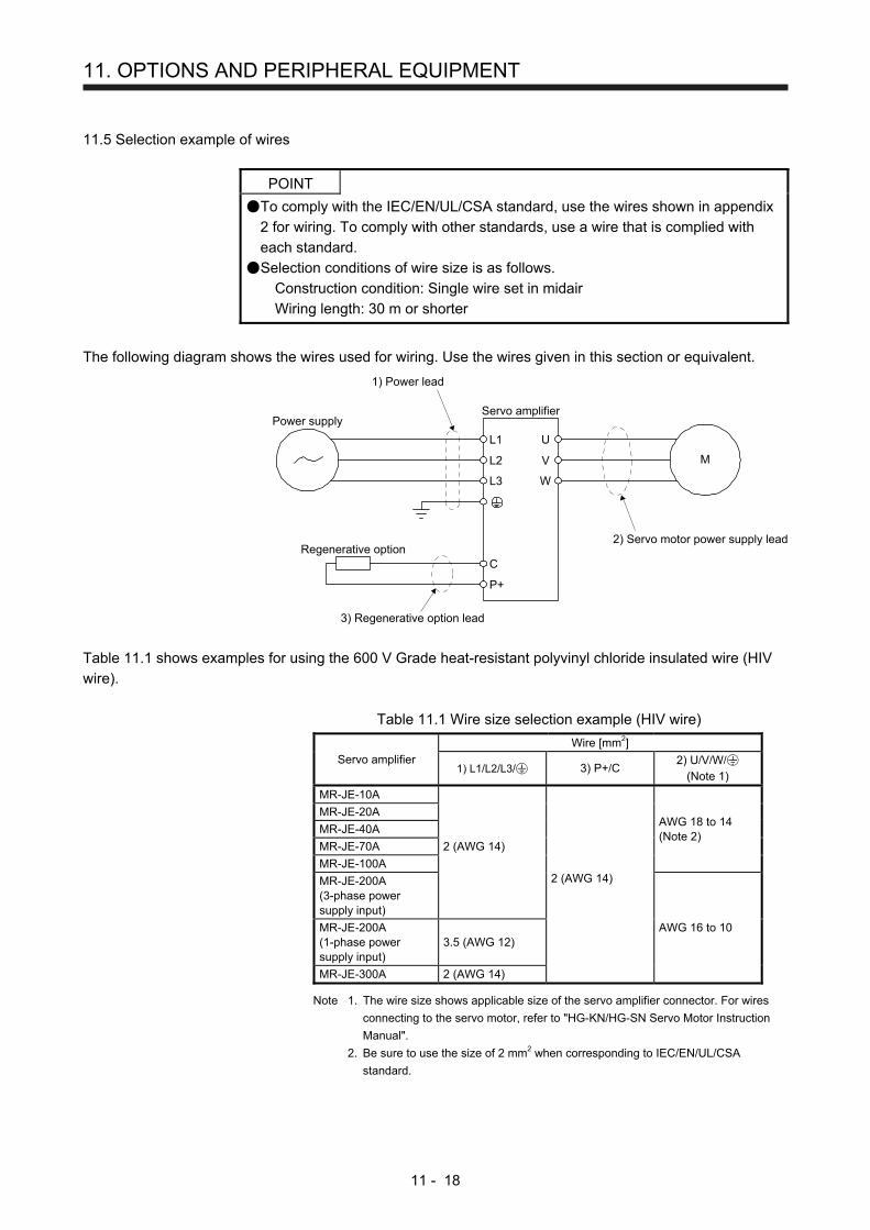
11. OPTIONS AND PERIPHERAL EQUIPMENT
11 - 18
11.5 Selection example of wires
POINT
To comply with the IEC/EN/UL/CSA standard, use the wires shown in appendix
2 for wiring. To comply with other standards, use a wire that is complied with
each standard.
Selection conditions of wire size is as follows.
Construction condition: Single wire set in midair
Wiring length: 30 m or shorter
The following diagram shows the wires used for wiring. Use the wires given in this section or equivalent.
3) Regenerative option lead
Regenerative optionC
P+
L1
L2
L3
1) Power lead
Power supplyServo amplifier
U
V
W
2) Servo motor power supply lead
M
Table 11.1 shows examples for using the 600 V Grade heat-resistant polyvinyl chloride insulated wire (HIV
wire).
Table 11.1 Wire size selection example (HIV wire)
Servo amplifier
Wire [mm2]
1) L1/L2/L3/ 3) P+/C 2) U/V/W/
(Note 1)
MR-JE-10A
MR-JE-20A AWG 18 to 14 (Note 2)
MR-JE-40A
MR-JE-70A 2 (AWG 14)
2 (AWG 14) MR-JE-100A
MR-JE-200A (3-phase power supply input)
AWG 16 to 10 MR-JE-200A (1-phase power supply input)
3.5 (AWG 12)
MR-JE-300A 2 (AWG 14)
Note 1. The wire size shows applicable size of the servo amplifier connector. For wires
connecting to the servo motor, refer to "HG-KN/HG-SN Servo Motor Instruction
Manual".
2. Be sure to use the size of 2 mm2 when corresponding to IEC/EN/UL/CSA
standard.

11. OPTIONS AND PERIPHERAL EQUIPMENT
11 - 19
11.6 Molded-case circuit breakers, fuses, magnetic contactors
CAUTION
To prevent the servo amplifier from smoke and a fire, select a molded-case circuit
breaker which shuts off with high speed.
Always use one molded-case circuit breaker and one magnetic contactor with one
servo amplifier.
When using a fuse instead of the molded-case circuit breaker, use the one having the specifications given in
this section.
Servo amplifier
Molded-case circuit breaker (Note 1, 4) Fuse
Magnetic contactor (Note 2)
Frame, rated current Voltage AC
[V] Class Current [A]
Voltage AC [V]
Power factor improving reactor is
not used
Power factor improving reactor is
used
MR-JE-10A 30 A frame 5 A 30 A frame 5 A
240 T
10
300
S-N10 S-T10
MR-JE-20A
MR-JE-40A 30 A frame 10 A 30 A frame 5 A 15
MR-JE-70A
30 A frame 15 A 30 A frame 10 A 20 MR-JE-100A (3-phase power supply input)
MR-JE-100A (1-phase power supply input)
30 A frame 15 A 30 A frame 15 A 30
MR-JE-200A 30 A frame 20 A 30 A frame 20 A 40 S-N20
(Note 3) S-T21
MR-JE-300A 30 A frame 30 A 30 A frame 30 A 70 S-N20 S-T21
Note 1. When having the servo amplifier comply with the IEC/EN/UL/CSA standard, refer to appendix 2.
2. Use a magnetic contactor with an operation delay time (interval between current being applied to the coil until closure of
contacts) of 80 ms or less.
3. S-N18 can be used when auxiliary contact is not required.
4. Use a molded-case circuit breaker which has the same or more operation characteristics than our lineup.
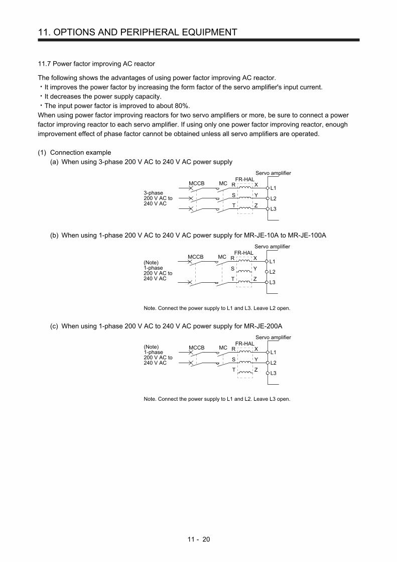
11. OPTIONS AND PERIPHERAL EQUIPMENT
11 - 20
11.7 Power factor improving AC reactor
The following shows the advantages of using power factor improving AC reactor.
It improves the power factor by increasing the form factor of the servo amplifier's input current.
It decreases the power supply capacity.
The input power factor is improved to about 80%.
When using power factor improving reactors for two servo amplifiers or more, be sure to connect a power
factor improving reactor to each servo amplifier. If using only one power factor improving reactor, enough
improvement effect of phase factor cannot be obtained unless all servo amplifiers are operated.
(1) Connection example
(a) When using 3-phase 200 V AC to 240 V AC power supply
Y
Z
S
T
MCMCCBFR-HAL
Servo amplifier
XRL1
L2
L3
3-phase200 V AC to240 V AC
(b) When using 1-phase 200 V AC to 240 V AC power supply for MR-JE-10A to MR-JE-100A
Y
Z
S
T
MCMCCBFR-HAL
Servo amplifier
XRL1
L2
(Note)1-phase200 V AC to240 V AC
L3
Note. Connect the power supply to L1 and L3. Leave L2 open.
(c) When using 1-phase 200 V AC to 240 V AC power supply for MR-JE-200A
Y
Z
S
T
MCMCCBFR-HAL
Servo amplifier
XRL1
L2
L3
(Note)1-phase200 V AC to240 V AC
Note. Connect the power supply to L1 and L2. Leave L3 open.
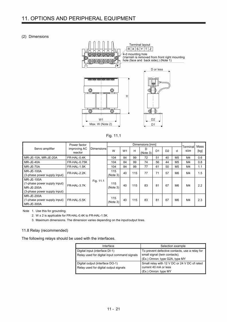
11. OPTIONS AND PERIPHERAL EQUIPMENT
11 - 21
(2) Dimensions
4-d mounting hole(Varnish is removed from front right mountinghole (face and back side).) (Note 1)
Terminal layout
R X ZS Y T
Max. W (Note 2)
W1
D1
D2
H
D or less
Fig. 11.1
Servo amplifier Power factor improving AC
reactor Dimensions
Dimensions [mm] Terminal
size Mass[kg] W W1 H
D (Note 3)
D1 D2 d
MR-JE-10A, MR-JE-20A FR-HAL-0.4K
Fig. 11.1
104 84 99 72 51 40 M5 M4 0.6
MR-JE-40A FR-HAL-0.75K 104 84 99 74 56 44 M5 M4 0.8
MR-JE-70A FR-HAL-1.5K 104 84 99 77 61 50 M5 M4 1.1
MR-JE-100A (3-phase power supply input)
FR-HAL-2.2K 115
(Note 3)40 115 77 71 57 M6 M4 1.5
MR-JE-100A (1-phase power supply input) MR-JE-200A (3-phase power supply input)
FR-HAL-3.7K 115
(Note 3)40 115 83 81 67 M6 M4 2.2
MR-JE-200A (1-phase power supply input) MR-JE-300A
FR-HAL-5.5K 115
(Note 3)40 115 83 81 67 M6 M4 2.3
Note 1. Use this for grounding.
2. W ± 2 is applicable for FR-HAL-0.4K to FR-HAL-1.5K.
3. Maximum dimensions. The dimension varies depending on the input/output lines.
11.8 Relay (recommended)
The following relays should be used with the interfaces.
Interface Selection example
Digital input (interface DI-1) Relay used for digital input command signals
To prevent defective contacts, use a relay for small signal (twin contacts). (Ex.) Omron: type G2A, type MY
Digital output (interface DO-1) Relay used for digital output signals
Small relay with 12 V DC or 24 V DC of rated current 40 mA or less (Ex.) Omron: type MY
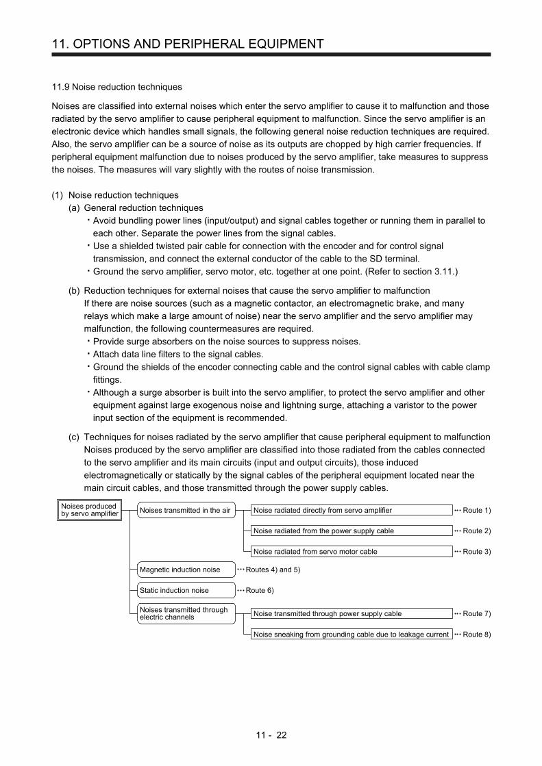
11. OPTIONS AND PERIPHERAL EQUIPMENT
11 - 22
11.9 Noise reduction techniques
Noises are classified into external noises which enter the servo amplifier to cause it to malfunction and those
radiated by the servo amplifier to cause peripheral equipment to malfunction. Since the servo amplifier is an
electronic device which handles small signals, the following general noise reduction techniques are required.
Also, the servo amplifier can be a source of noise as its outputs are chopped by high carrier frequencies. If
peripheral equipment malfunction due to noises produced by the servo amplifier, take measures to suppress
the noises. The measures will vary slightly with the routes of noise transmission.
(1) Noise reduction techniques
(a) General reduction techniques
Avoid bundling power lines (input/output) and signal cables together or running them in parallel to
each other. Separate the power lines from the signal cables.
Use a shielded twisted pair cable for connection with the encoder and for control signal
transmission, and connect the external conductor of the cable to the SD terminal.
Ground the servo amplifier, servo motor, etc. together at one point. (Refer to section 3.11.)
(b) Reduction techniques for external noises that cause the servo amplifier to malfunction
If there are noise sources (such as a magnetic contactor, an electromagnetic brake, and many
relays which make a large amount of noise) near the servo amplifier and the servo amplifier may
malfunction, the following countermeasures are required.
Provide surge absorbers on the noise sources to suppress noises.
Attach data line filters to the signal cables.
Ground the shields of the encoder connecting cable and the control signal cables with cable clamp
fittings.
Although a surge absorber is built into the servo amplifier, to protect the servo amplifier and other
equipment against large exogenous noise and lightning surge, attaching a varistor to the power
input section of the equipment is recommended.
(c) Techniques for noises radiated by the servo amplifier that cause peripheral equipment to malfunction
Noises produced by the servo amplifier are classified into those radiated from the cables connected
to the servo amplifier and its main circuits (input and output circuits), those induced
electromagnetically or statically by the signal cables of the peripheral equipment located near the
main circuit cables, and those transmitted through the power supply cables.
Noises producedby servo amplifier Noises transmitted in the air Noise radiated directly from servo amplifier
Noise radiated from the power supply cable
Noise radiated from servo motor cable
Magnetic induction noise
Static induction noise
Noises transmitted throughelectric channels Noise transmitted through power supply cable
Noise sneaking from grounding cable due to leakage current
Routes 4) and 5)
Route 1)
Route 2)
Route 3)
Route 7)
Route 8)
Route 6)
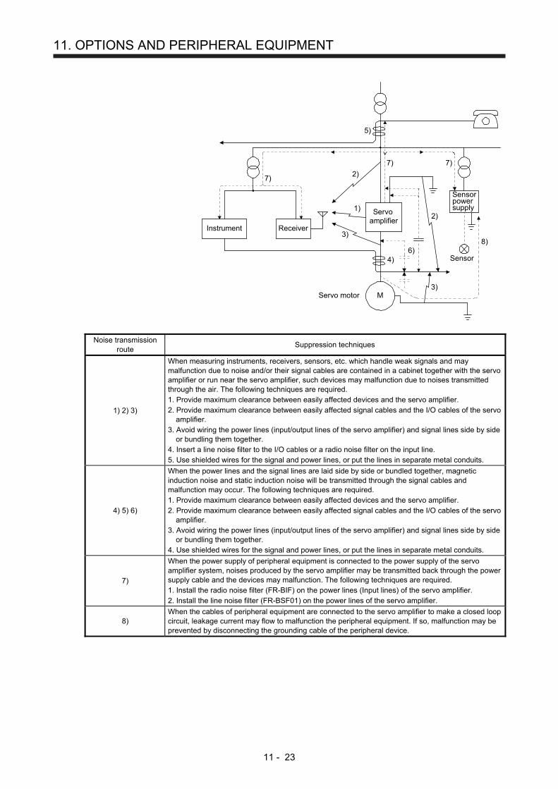
11. OPTIONS AND PERIPHERAL EQUIPMENT
11 - 23
Instrument Receiver
Servoamplifier
Servo motor M
2)
2)
8)
1)
7)
7) 7)
5)
3)
4)6)
3)
Sensor power supply
Sensor
Noise transmission route
Suppression techniques
1) 2) 3)
When measuring instruments, receivers, sensors, etc. which handle weak signals and may malfunction due to noise and/or their signal cables are contained in a cabinet together with the servo amplifier or run near the servo amplifier, such devices may malfunction due to noises transmitted through the air. The following techniques are required. 1. Provide maximum clearance between easily affected devices and the servo amplifier. 2. Provide maximum clearance between easily affected signal cables and the I/O cables of the servo
amplifier. 3. Avoid wiring the power lines (input/output lines of the servo amplifier) and signal lines side by side
or bundling them together. 4. Insert a line noise filter to the I/O cables or a radio noise filter on the input line. 5. Use shielded wires for the signal and power lines, or put the lines in separate metal conduits.
4) 5) 6)
When the power lines and the signal lines are laid side by side or bundled together, magnetic induction noise and static induction noise will be transmitted through the signal cables and malfunction may occur. The following techniques are required. 1. Provide maximum clearance between easily affected devices and the servo amplifier. 2. Provide maximum clearance between easily affected signal cables and the I/O cables of the servo
amplifier. 3. Avoid wiring the power lines (input/output lines of the servo amplifier) and signal lines side by side
or bundling them together. 4. Use shielded wires for the signal and power lines, or put the lines in separate metal conduits.
7)
When the power supply of peripheral equipment is connected to the power supply of the servo amplifier system, noises produced by the servo amplifier may be transmitted back through the power supply cable and the devices may malfunction. The following techniques are required. 1. Install the radio noise filter (FR-BIF) on the power lines (Input lines) of the servo amplifier. 2. Install the line noise filter (FR-BSF01) on the power lines of the servo amplifier.
8) When the cables of peripheral equipment are connected to the servo amplifier to make a closed loop circuit, leakage current may flow to malfunction the peripheral equipment. If so, malfunction may be prevented by disconnecting the grounding cable of the peripheral device.
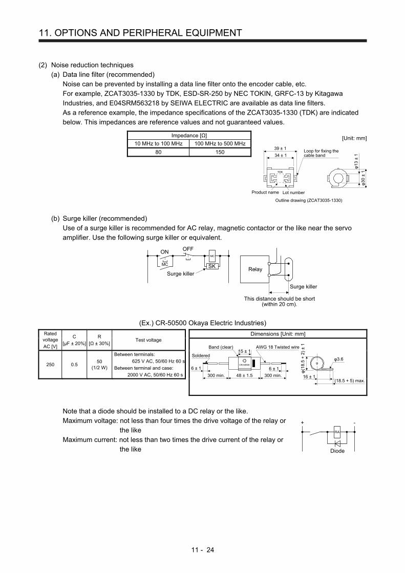
11. OPTIONS AND PERIPHERAL EQUIPMENT
11 - 24
(2) Noise reduction techniques
(a) Data line filter (recommended)
Noise can be prevented by installing a data line filter onto the encoder cable, etc.
For example, ZCAT3035-1330 by TDK, ESD-SR-250 by NEC TOKIN, GRFC-13 by Kitagawa
Industries, and E04SRM563218 by SEIWA ELECTRIC are available as data line filters.
As a reference example, the impedance specifications of the ZCAT3035-1330 (TDK) are indicated
below. This impedances are reference values and not guaranteed values.
Impedance [Ω] [Unit: mm]
Outline drawing (ZCAT3035-1330)
Loop for fixing thecable band
Lot numberProduct name
TDK
39 ± 1
34 ± 1
φ13
± 1
φ30
± 1
10 MHz to 100 MHz 100 MHz to 500 MHz
80 150
(b) Surge killer (recommended)
Use of a surge killer is recommended for AC relay, magnetic contactor or the like near the servo
amplifier. Use the following surge killer or equivalent.
MC
SK
Surge killer
RelaySurge killer
MC
ON OFF
This distance should be short(within 20 cm).
(Ex.) CR-50500 Okaya Electric Industries)
Rated voltage
AC [V]
C
[µF ± 20%]
R
[Ω ± 30%] Test voltage
Dimensions [Unit: mm]
6 ± 1
300 min. 300 min.
Soldered
Band (clear) AWG 18 Twisted wire15 ± 1
48 ± 1.5
CR-50500
6 ± 1
16 ± 1(18.5 + 5) max.
φ3.6
φ(18
.5 +
2)
± 1
250 0.5 50
(1/2 W)
Between terminals:
625 V AC, 50/60 Hz 60 s
Between terminal and case:
2000 V AC, 50/60 Hz 60 s
Note that a diode should be installed to a DC relay or the like.
Maximum voltage: not less than four times the drive voltage of the relay or
the like
Maximum current: not less than two times the drive current of the relay or
the like
-+
Diode
RA

11. OPTIONS AND PERIPHERAL EQUIPMENT
11 - 25
(c) Cable clamp fitting AERSBAN-_SET
Generally, the grounding of the shielded wire may only be connected to the connector's SD terminal.
However, the effect can be increased by directly connecting the cable to an grounding plate as
shown below.
Install the grounding plate near the servo amplifier for the encoder cable. Peel part of the cable
sheath to expose the external conductor, and press that part against the grounding plate with the
cable clamp. If the cable is thin, clamp several cables in a bunch.
The cable clamp comes as a set with the grounding plate.
[Unit: mm]
Cable clamp(A, B)
Cable
Grounding plate
External conductor
Clamp section diagram
40
Strip the cable sheath ofthe clamped area. cutter
cable
Dimensions
[Unit: mm]
Grounding plate
(Note) M4 screw
113
6
C A
6 22
17.5
35
35
7
24 0 -0
.2
B ±
0.3
2-φ5 holeinstallation hole
[Unit: mm]
Clamp section diagram
L or less 10
3024
+ 0
.3
0
Note. Screw hole for grounding. Connect it to the grounding plate of the cabinet.
Model A B C Accessory fittings Clamp fitting L
AERSBAN-DSET 100 86 30 Clamp A: 2pcs. A 70
AERSBAN-ESET 70 56 Clamp B: 1pc. B 45
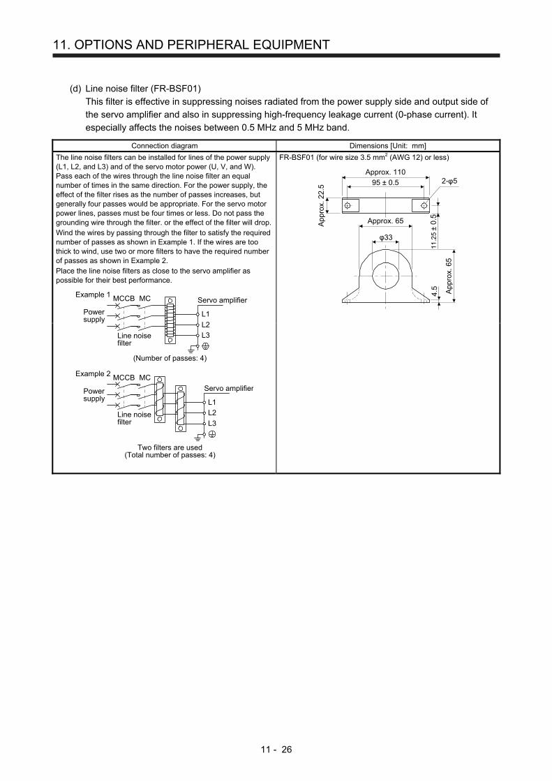
11. OPTIONS AND PERIPHERAL EQUIPMENT
11 - 26
(d) Line noise filter (FR-BSF01)
This filter is effective in suppressing noises radiated from the power supply side and output side of
the servo amplifier and also in suppressing high-frequency leakage current (0-phase current). It
especially affects the noises between 0.5 MHz and 5 MHz band.
Connection diagram Dimensions [Unit: mm]
The line noise filters can be installed for lines of the power supply (L1, L2, and L3) and of the servo motor power (U, V, and W). Pass each of the wires through the line noise filter an equal number of times in the same direction. For the power supply, the effect of the filter rises as the number of passes increases, but generally four passes would be appropriate. For the servo motor power lines, passes must be four times or less. Do not pass the grounding wire through the filter. or the effect of the filter will drop. Wind the wires by passing through the filter to satisfy the required number of passes as shown in Example 1. If the wires are too thick to wind, use two or more filters to have the required number of passes as shown in Example 2. Place the line noise filters as close to the servo amplifier as possible for their best performance.
MCMCCBExample 1
Powersupply
Powersupply
Servo amplifier
Line noisefilter
L1
L2
L3
(Number of passes: 4)
MCMCCB
Line noisefilter
Example 2
Servo amplifier
L1
L2
L3
Two filters are used(Total number of passes: 4)
FR-BSF01 (for wire size 3.5 mm2 (AWG 12) or less)
φ33
4.5
Approx. 110
95 ± 0.5
App
rox.
22.
5
App
rox.
65
Approx. 65
2-φ5
11
.25
± 0.
5
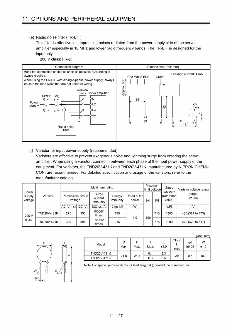
11. OPTIONS AND PERIPHERAL EQUIPMENT
11 - 27
(e) Radio noise filter (FR-BIF)
This filter is effective in suppressing noises radiated from the power supply side of the servo
amplifier especially in 10 MHz and lower radio frequency bands. The FR-BIF is designed for the
input only.
200 V class: FR-BIF
Connection diagram Dimensions [Unit: mm]
Make the connection cables as short as possible. Grounding is always required. When using the FR-BIF with a single-phase power supply, always insulate the lead wires that are not used for wiring.
Radio noisefilter
Servo amplifier
Powersupply
MCMCCB
L3
L2
L1
Terminalblock
hole
Leakage current: 4 mA
29
58
42
4
Red BlueWhite Green
4429 7
φ5
App
rox.
300
(f) Varistor for input power supply (recommended)
Varistors are effective to prevent exogenous noise and lightning surge from entering the servo
amplifier. When using a varistor, connect it between each phase of the input power supply of the
equipment. For varistors, the TND20V-431K and TND20V-471K, manufactured by NIPPON CHEMI-
CON, are recommended. For detailed specification and usage of the varistors, refer to the
manufacturer catalog.
Power supply voltage
Varistor
Maximum rating Maximum
limit voltageStatic
capacity (reference
value)
Varistor voltage rating(range) V1 mA
Permissible circuit voltage
Surge current
immunity
Energy immunity
Rated pulse power [A] [V]
AC [Vrms] DC [V] 8/20 µs [A] 2 ms [J] [W] [pF] [V]
200 V class
TND20V-431K 275 350 10000/1
times 195
1.0 100710 1300 430 (387 to 473)
TND20V-471K 300 385 7000/2 times
215 775 1200 470 (423 to 517)
[Unit: mm]
W E
H
D
L
T
d
Model D
Max. H
Max. T
Max. E
±1.0
(Note) L
min.
φd ±0.05
W ±1.0
TND20V-431K 21.5 24.5
6.4 3.3 20 0.8 10.0
TND20V-471K 6.6 3.5
Note. For special purpose items for lead length (L), contact the manufacturer.

11. OPTIONS AND PERIPHERAL EQUIPMENT
11 - 28
11.10 Earth-leakage current breaker
(1) Selection method
High-frequency chopper currents controlled by pulse width modulation flow in the AC servo circuits.
Leakage currents containing harmonic contents are larger than those of the motor which is run with a
commercial power supply.
Select an earth-leakage current breaker according to the following formula, and ground the servo
amplifier, servo motor, etc. securely.
To minimize leakage currents, make the input and output cables as short as possible, and make the
grounding cable longer than 30 cm.
Rated sensitivity current ≥ 10 • Ig1 + Ign + Iga + K • (Ig2 + Igm) [mA] ···································· (11.1)
Ign
Noise filterCable
Ig1 Iga Ig2 Igm
MServo
amplifier
NVCable
Earth-leakage current breaker K
Type Mitsubishi products
Models provided with harmonic and surge reduction techniques
NV-SP NV-SW NV-CP NV-CW NV-HW
1
General models BV-C1 NFB NV-L
3
Ig1: Leakage current on the electric channel from the earth-leakage current breaker to the input
terminals of the servo amplifier (Found from Fig. 11.2.)
Ig2: Leakage current on the electric channel from the output terminals of the servo amplifier to the servo
motor (found from Fig. 11.2.)
Ign: Leakage current when a filter is connected to the input side (4.4 mA per one FR-BIF)
Iga: Leakage current of the servo amplifier (Found from table 11.3.)
Igm: Leakage current of the servo motor (Found from table 11.2.)
Leak
age
curr
ent [
mA
]
Cable size [mm2]
120
100
80
60
40
20
02 5.5 14
3.5 838100
2230
6015080
Fig. 11.2 Example of leakage current per km (lg1, lg2) for CV cable run in metal conduit

11. OPTIONS AND PERIPHERAL EQUIPMENT
11 - 29
Table 11.2 Servo motor leakage current example (lgm)
Servo motor power [kW] Leakage current [mA]
0.1 to 1 0.1
1.5 to 2 0.2
3 0.3
Table 11.3 Servo amplifier leakage current example (Iga)
Servo amplifier capacity [kW] Leakage current [mA]
0.1 to 0.4 0.1
0.75 to 3 0.15
Table 11.4 Earth-leakage current breaker selection example
Servo amplifier capacity [kW] Rated sensitivity current of earth-
leakage current breaker [mA]
MR-JE-10A to MR-JE-300A 15
(2) Selection example
Indicated below is an example of selecting an earth-leakage current breaker under the following
conditions.
Servo motorHG-KN43_
2 mm2 × 5 m 2 mm2 × 5 m
M
NV
Ig1 Iga Ig2 Igm
Servo amplifierMR-JE-40A
Use an earth-leakage current breaker designed for suppressing harmonics/surges.
Find the terms of equation (11.1) from the diagram.
Ig1 = 20 • 5
1000 = 0.1 [mA]
Ig2 = 20 • 5
1000 = 0.1 [mA]
Ign = 0 (not used)
Iga = 0.1 [mA]
Igm = 0.1 [mA]
Insert these values in equation (11.1).
Ig ≥ 10 • 0.1 + 0 + 0.1 + 1 • (0.1 + 0.1)
≥ 4 [mA]
According to the result of calculation, use an earth-leakage current breaker having the rated sensitivity
current (Ig) of 4.0 mA or more.
Use an earth-leakage current breaker having Ig of 15 mA with the NV-SP/SW/CP/CW/HW series.

11. OPTIONS AND PERIPHERAL EQUIPMENT
11 - 30
11.11 EMC filter (recommended)
It is recommended that one of the following filters be used to comply with EN EMC directive. Some EMC
filters have large in leakage current. When using an EMC filter, always use one for each servo amplifier.
(1) Combination with the servo amplifier
Servo amplifier
Recommended filter (Soshin Electric)
Mass [kg] Model
Rated current [A]
Rated voltage [V AC]
Leakage current [mA]
MR-JE-10A to MR-JE-100A
(Note) HF3010A-UN
10 250 5
3.5
MR-JE-200A, MR-JE-300A
(Note) HF3030A-UN
30 5.5
Note. A surge protector is separately required to use any of these EMC filters.
(2) Connection example
(a) When using 3-phase 200 V AC to 240 V AC power supply
MCCB
Servo amplifier
1
2
3
(Note)Surge protector(RSPD-250-U4)(OKAYA Electric Industries Co., Ltd.)
3-phase200 V AC to240 V AC
1 2 3
MC
EMC filter
L1
L2
L3
4
5
6
E
Note. The example is when a surge protector is connected.
(b) When using 1-phase 200 V AC to 240 V AC power supply for MR-JE-10A to MR-JE-100A
MCCB
Servo amplifier
1
2
3
(Note 2)Surge protector(RSPD-250-U4)(OKAYA Electric Industries Co., Ltd.)
(Note 1)1-phase200 V AC to240 V AC
1 2 3
MC
EMC filter
L1
L2
L3
4
5
6
E
Note 1. Connect the power supply to L1 and L3. Leave L2 open.
2. The example is when a surge protector is connected.
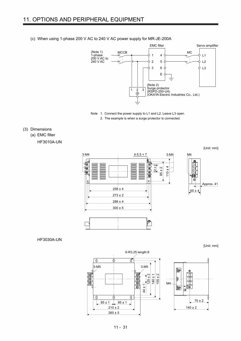
11. OPTIONS AND PERIPHERAL EQUIPMENT
11 - 31
(c) When using 1-phase 200 V AC to 240 V AC power supply for MR-JE-200A
MCCB
Servo amplifier
1
2
3
(Note 2)Surge protector(RSPD-250-U4)(OKAYA Electric Industries Co., Ltd.)
(Note 1)1-phase200 V AC to240 V AC
1 2 3
MC
EMC filter
L1
L2
L3
4
5
6
E
Note 1. Connect the power supply to L1 and L2. Leave L3 open.
2. The example is when a surge protector is connected.
(3) Dimensions
(a) EMC filter
HF3010A-UN
[Unit: mm]
32 ±
2
85 ±
2
110
± 4
258 ± 4
273 ± 2
288 ± 4
300 ± 5
M4
IN
3-M4
65 ± 4
Approx. 41
4-5.5 × 73-M4
HF3030A-UN
[Unit: mm]
125
± 2
44 ±
1
260 ± 5
140 ± 2
70 ± 2
140
± 1
155
± 2
3-M5
6-R3.25 length:8
3-M5
M4
85 ± 1
210 ± 2
85 ± 1
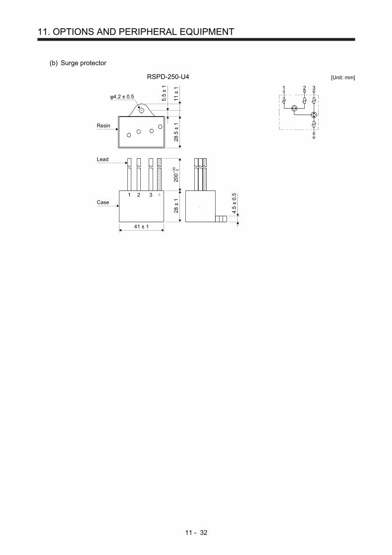
11. OPTIONS AND PERIPHERAL EQUIPMENT
11 - 32
(b) Surge protector
RSPD-250-U4
41 ± 1
28.5
± 1
28
± 1
φ4.2 ± 0.5 5.5
± 1
11 ±
1+
30 0
200
4.5
± 0.
51 32
Lead
Case
Resin
[Unit: mm]
1 2 3
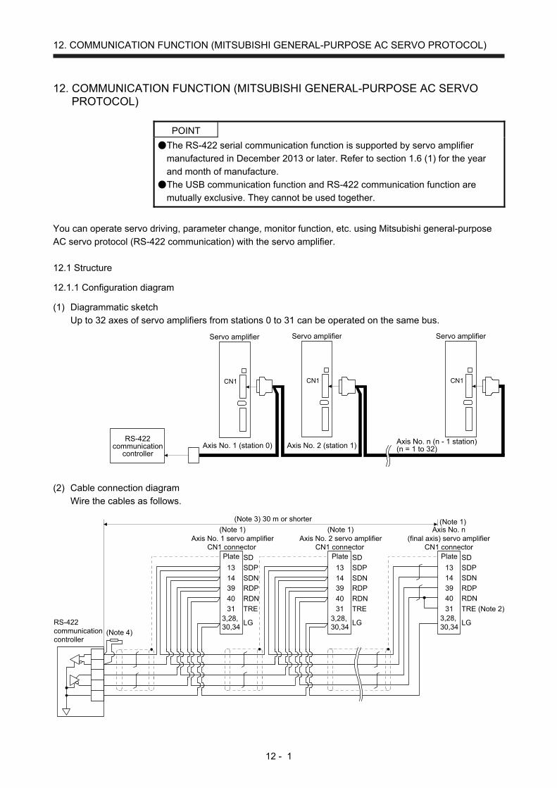
12. COMMUNICATION FUNCTION (MITSUBISHI GENERAL-PURPOSE AC SERVO PROTOCOL)
12 - 1
12. COMMUNICATION FUNCTION (MITSUBISHI GENERAL-PURPOSE AC SERVO
PROTOCOL)
POINT
The RS-422 serial communication function is supported by servo amplifier
manufactured in December 2013 or later. Refer to section 1.6 (1) for the year
and month of manufacture.
The USB communication function and RS-422 communication function are
mutually exclusive. They cannot be used together.
You can operate servo driving, parameter change, monitor function, etc. using Mitsubishi general-purpose
AC servo protocol (RS-422 communication) with the servo amplifier.
12.1 Structure
12.1.1 Configuration diagram
(1) Diagrammatic sketch
Up to 32 axes of servo amplifiers from stations 0 to 31 can be operated on the same bus.
Axis No. n (n - 1 station)(n = 1 to 32)Axis No. 2 (station 1)Axis No. 1 (station 0)
Servo amplifier
CN1
Servo amplifier
CN1
Servo amplifier
CN1
RS-422communication
controller
(2) Cable connection diagram
Wire the cables as follows.
13
Plate
39
14
31
40
3,28,30,34
SDP
SD
RDP
SDN
TRE (Note 2)
RDN
LG
(Note 1)Axis No. 1 servo amplifier
CN1 connector
RS-422communicationcontroller
(Note 3) 30 m or shorter
(Note 1)Axis No. 2 servo amplifier
CN1 connector
(Note 1)
(Note 4)
13
Plate
3914
31
40
3,28,30,34
SDP
SD
RDPSDN
TRE
RDN
LG
13
Plate
3914
31
40
3,28,30,34
SDP
SD
RDPSDN
TRE
RDN
LG
Axis No. n(final axis) servo amplifier
CN1 connector

12. COMMUNICATION FUNCTION (MITSUBISHI GENERAL-PURPOSE AC SERVO PROTOCOL)
12 - 2
Note 1. Connector set MR-J3CN1 (3M or equivalent)
Connector: 10150-3000PE
Shell kit: 10350-52F0-008
2. Connect between TRE and RDN of the final axis servo amplifier.
3. The overall length is 30 m or less in low-noise environment.
4. If the RS-422 communication controller does not have a termination resistor, terminate it with a 150 Ω resistor.
12.1.2 Precautions for using RS422/USB communication function
Note the following to prevent an electric shock and malfunction of the servo amplifier.
(1) Power connection of personal computers
Connect your personal computer with the following procedures.
(a) When you use a personal computer with AC power supply
1) When using a personal computer with a three-core power plug or power plug with grounding wire,
use a three-pin socket or ground the grounding wire.
2) When your personal computer has two-core plug and has no grounding wire, connect the
personal computer to the servo amplifier with the following procedures.
a) Disconnect the power plug of the personal computer from an AC power socket.
b) Check that the power plug was disconnected and connect the device to the servo amplifier.
c) Connect the power plug of the personal computer to the AC power socket.
(b) When you use a personal computer with battery
You can use as it is.
(2) Connection with other devices using servo amplifier communication function
When the servo amplifier is charged with electricity due to connection with a personal computer and the
charged servo amplifier is connected with other devices, the servo amplifier or the connected devices
may malfunction. Connect the servo amplifier and other devices with the following procedures.
(a) Shut off the power of the device for connecting with the servo amplifier.
(b) Shut off the power of the servo amplifier which was connected with the personal computer and
check the charge lamp is off.
(c) Connect the device with the servo amplifier.
(d) Turn on the power of the servo amplifier and the device.
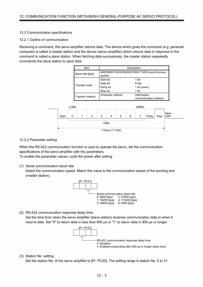
12. COMMUNICATION FUNCTION (MITSUBISHI GENERAL-PURPOSE AC SERVO PROTOCOL)
12 - 3
12.2 Communication specifications
12.2.1 Outline of communication
Receiving a command, this servo amplifier returns data. The device which gives the command (e.g. personal
computer) is called a master station and the device (servo amplifier) which returns data in response to the
command is called a slave station. When fetching data successively, the master station repeatedly
commands the slave station to send data.
Item Description
Baud rate [bps] 4800/9600/19200/38400/57600/115200 asynchronous system
Transfer code
Start bit Data bit Parity bit Stop bit
1 bit 8 bits 1 bit (even) 1 bit
Transfer method Character method Half-duplex
communication method
1 frame (11 bits)
Data
Start 0 1 2 3 4 5 6 7 Parity StopNextstart
(LSB) (MSB)
12.2.2 Parameter setting
When the RS-422 communication function is used to operate the servo, set the communication
specifications of the servo amplifier with the parameters.
To enable the parameter values, cycle the power after setting.
(1) Serial communication baud rate
Select the communication speed. Match this value to the communication speed of the sending end
(master station).
Serial communication baud rate0: 9600 [bps] 3: 57600 [bps]1: 19200 [bps] 4: 115200 [bps]2: 38400 [bps] 6: 4800 [bps]
[Pr. PC21]
(2) RS-422 communication response delay time
Set the time from when the servo amplifier (slave station) receives communication data to when it
returns data. Set "0" to return data in less than 800 μs or "1" to return data in 800 μs or longer.
RS-422 communication response delay time0: Disabled1: Enabled (responding after 800
[Pr. PC21]
s or longer delay time)
(3) Station No. setting
Set the station No. of the servo amplifier to [Pr. PC20]. The setting range is station No. 0 to 31.
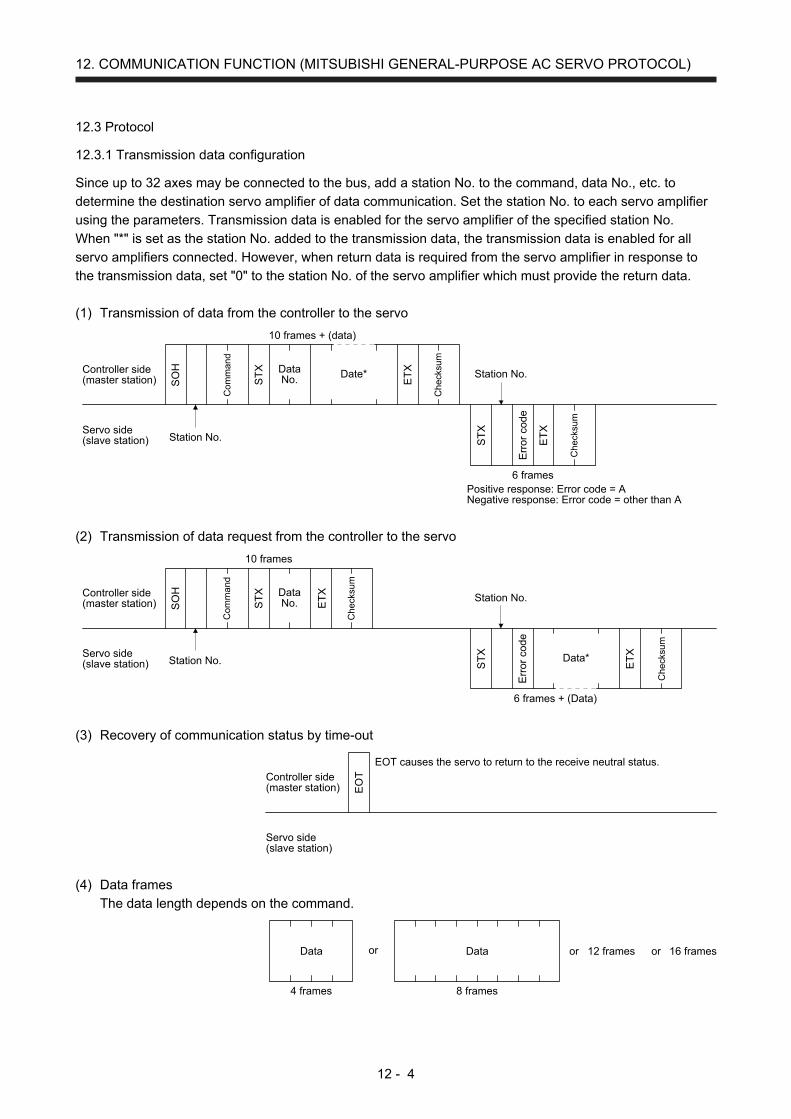
12. COMMUNICATION FUNCTION (MITSUBISHI GENERAL-PURPOSE AC SERVO PROTOCOL)
12 - 4
12.3 Protocol
12.3.1 Transmission data configuration
Since up to 32 axes may be connected to the bus, add a station No. to the command, data No., etc. to
determine the destination servo amplifier of data communication. Set the station No. to each servo amplifier
using the parameters. Transmission data is enabled for the servo amplifier of the specified station No.
When "*" is set as the station No. added to the transmission data, the transmission data is enabled for all
servo amplifiers connected. However, when return data is required from the servo amplifier in response to
the transmission data, set "0" to the station No. of the servo amplifier which must provide the return data.
(1) Transmission of data from the controller to the servo
Date*
SO
H
ST
X
Com
man
d
DataNo. E
TX
ST
X
ET
X
Che
cksu
m
Che
cksu
m
10 frames + (data)
6 framesPositive response: Error code = ANegative response: Error code = other than A
Station No.
Station No.
Controller side(master station)
Servo side(slave station)
Err
or c
ode
(2) Transmission of data request from the controller to the servo
Data*
SO
H
ST
X
Com
man
d
DataNo. E
TX
ST
X
ET
X
Che
cksu
m
Che
cksu
m
Station No.
Station No.
Controller side(master station)
Servo side(slave station)
Err
or c
ode
10 frames
6 frames + (Data)
(3) Recovery of communication status by time-out
EOT causes the servo to return to the receive neutral status.
EO
TController side(master station)
Servo side(slave station)
(4) Data frames
The data length depends on the command.
12 framesData
4 frames
Data
8 frames
or or or 16 frames
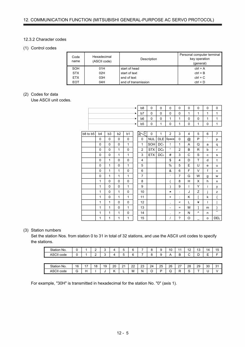
12. COMMUNICATION FUNCTION (MITSUBISHI GENERAL-PURPOSE AC SERVO PROTOCOL)
12 - 5
12.3.2 Character codes
(1) Control codes
Code name
Hexadecimal (ASCII code)
Description Personal computer terminal
key operation (general)
SOH STX ETX EOT
01H 02H 03H 04H
start of head start of text end of text end of transmission
ctrl + A ctrl + B ctrl + C ctrl + D
(2) Codes for data
Use ASCII unit codes.
b8
b7
b6
b5
0
0
0
0
0
0
0
1
0
0
1
0
0
0
1
1
0
1
0
0
0
1
0
1
0
1
1
0
0
1
1
1
0
1
2
3
4
5
6
7
8
9
10
11
12
13
14
15
NUL
SOH
STX
ETX
DLE
DC1
DC2
DC3
!
“
#
$
%
‘
(
)
+
,
-
.
/
Space 0
1
2
3
4
5
6
7
8
9
:
;
<
=
>
?
@
A
B
C
D
E
F
G
H
I
J
K
L
M
N
O
P
Q
R
S
T
U
V
W
X
Y
Z
[
¥
]
^
_
`
a
b
c
d
e
f
g
h
i
j
k
l
m
n
o
p
q
r
s
t
u
v
w
x
y
z
|
¯
DEL
0
0
0
0
0
0
0
0
1
1
1
1
1
1
1
1
0
0
0
0
1
1
1
1
0
0
0
0
1
1
1
1
0
0
1
1
0
0
1
1
0
0
1
1
0
0
1
1
0
1
0
1
0
1
0
1
0
1
0
1
0
1
0
1
b8 to b5 R C 0 1 2 3b4 b3 b2 b1 4 5 6 7
(3) Station numbers
Set the station Nos. from station 0 to 31 in total of 32 stations, and use the ASCII unit codes to specify
the stations.
Station No. 0 1 2 3 4 5 6 7 8 9 10 11 12 13 14 15
ASCII code 0 1 2 3 4 5 6 7 8 9 A B C D E F
Station No. 16 17 18 19 20 21 22 23 24 25 26 27 28 29 30 31
ASCII code G H I J K L M N O P Q R S T U V
For example, "30H" is transmitted in hexadecimal for the station No. "0" (axis 1).
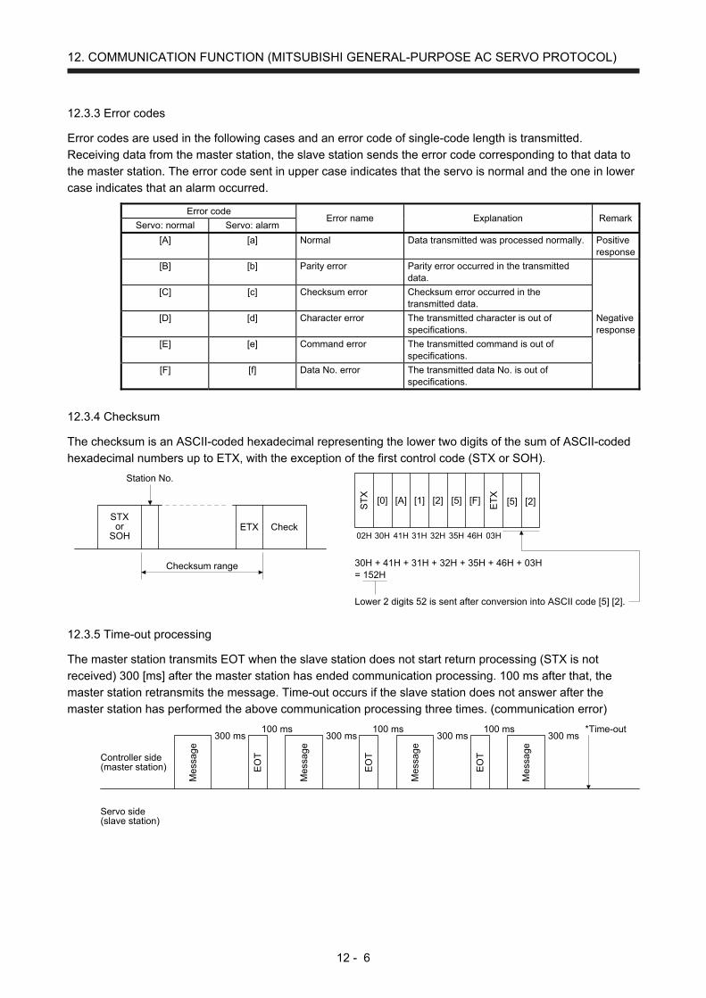
12. COMMUNICATION FUNCTION (MITSUBISHI GENERAL-PURPOSE AC SERVO PROTOCOL)
12 - 6
12.3.3 Error codes
Error codes are used in the following cases and an error code of single-code length is transmitted.
Receiving data from the master station, the slave station sends the error code corresponding to that data to
the master station. The error code sent in upper case indicates that the servo is normal and the one in lower
case indicates that an alarm occurred.
Error code Error name Explanation Remark
Servo: normal Servo: alarm
[A] [a] Normal Data transmitted was processed normally. Positive response
[B] [b] Parity error Parity error occurred in the transmitted data.
Negative response
[C] [c] Checksum error Checksum error occurred in the transmitted data.
[D] [d] Character error The transmitted character is out of specifications.
[E] [e] Command error The transmitted command is out of specifications.
[F] [f] Data No. error The transmitted data No. is out of specifications.
12.3.4 Checksum
The checksum is an ASCII-coded hexadecimal representing the lower two digits of the sum of ASCII-coded
hexadecimal numbers up to ETX, with the exception of the first control code (STX or SOH).
STXor
SOHETX Check
Checksum range
Station No.
[5][2]
ST
X
30H + 41H + 31H + 32H + 35H + 46H + 03H= 152H
[0] [A] [1] [F] [5] [2]ET
X
02H 30H 41H 31H 32H 35H 46H 03H
Lower 2 digits 52 is sent after conversion into ASCII code [5] [2].
12.3.5 Time-out processing
The master station transmits EOT when the slave station does not start return processing (STX is not
received) 300 [ms] after the master station has ended communication processing. 100 ms after that, the
master station retransmits the message. Time-out occurs if the slave station does not answer after the
master station has performed the above communication processing three times. (communication error)
Mes
sage
300 ms
Controller side(master station)
Servo side(slave station)
EO
T
100 ms
Mes
sage
300 ms
EO
T
100 ms
Mes
sage
300 ms
EO
T
100 ms
Mes
sage
300 ms*Time-out

12. COMMUNICATION FUNCTION (MITSUBISHI GENERAL-PURPOSE AC SERVO PROTOCOL)
12 - 7
12.3.6 Retry processing
When a fault occurs in communication between the master and slave stations, the error code in the
response data from the slave station is a negative response code ([B] to [F], [b] to [f]). In this case, the
master station retransmits the message which was sent at the occurrence of the fault (retry processing). A
communication error occurs if the above processing is repeated and results in the error three or more
consecutive times. S
TX
Mes
sage
Mes
sage
*Communication error
Mes
sage
Station No. Station No.Station No.
Controller side(master station)
Servo side(slave station) S
TX
ST
X
Similarly, when the master station detects a fault (e.g. checksum, parity) in the response data from the slave
station, the master station retransmits the message which was sent at the occurrence of the fault. A
communication error occurs if the retry processing is performed three times.
12.3.7 Initialization
After the slave station is switched on, it cannot return to communication until the internal initialization
processing terminates. Hence, at power-on, ordinary communication should be started after.
(1) Wait for 3.5 s or longer after the slave station is switched on.
(2) Check that normal communication can be made by reading the parameter or other data which does not
pose any safety problems.
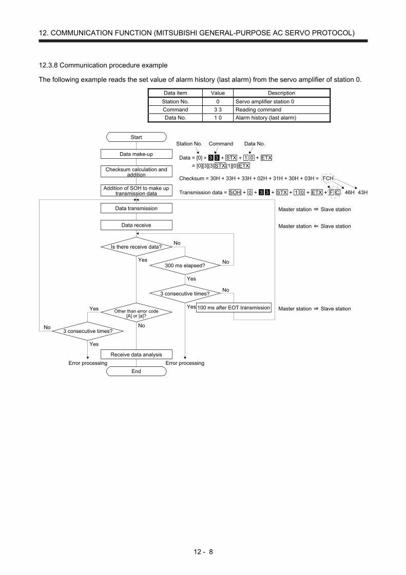
12. COMMUNICATION FUNCTION (MITSUBISHI GENERAL-PURPOSE AC SERVO PROTOCOL)
12 - 8
12.3.8 Communication procedure example
The following example reads the set value of alarm history (last alarm) from the servo amplifier of station 0.
Data item Value Description
Station No. 0 Servo amplifier station 0
Command 3 3 Reading command
Data No. 1 0 Alarm history (last alarm)
Data = [0]
= [0][3][3]
Transmission data =
Other than error code[A] or [a]?
3 consecutive times?
300 ms elapsed?
Start
Data make-up
Checksum calculation andaddition
Addition of SOH to make uptransmission data
Data transmission
Data receive
3 consecutive times?
Receive data analysis
End
100 ms after EOT transmission
Error processingError processing
No
Yes
Yes
Yes
No
No
NoNo
Yes
Yes
Master station
Is there receive data?
Command Data No.
Checksum = 30H + 33H + 33H + 02H + 31H + 30H + 03H =
46H 43H
Station No.
Slave station
Master station Slave station
Master station Slave station
ETXSTX
ETXSTX33 1 0+ + + +
ETXSOH 0STX33 1 CF0+ + + + + +
FCH
[1][0]
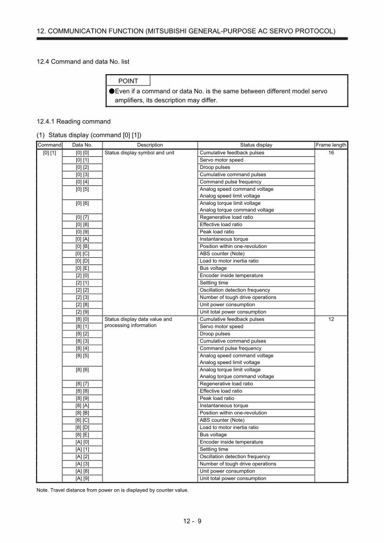
12. COMMUNICATION FUNCTION (MITSUBISHI GENERAL-PURPOSE AC SERVO PROTOCOL)
12 - 9
12.4 Command and data No. list
POINT
Even if a command or data No. is the same between different model servo
amplifiers, its description may differ.
12.4.1 Reading command
(1) Status display (command [0] [1]) Command Data No. Description Status display Frame length
[0] [1] [0] [0] Status display symbol and unit Cumulative feedback pulses 16
[0] [1] Servo motor speed
[0] [2] Droop pulses
[0] [3] Cumulative command pulses
[0] [4] Command pulse frequency
[0] [5] Analog speed command voltage Analog speed limit voltage
[0] [6] Analog torque limit voltage Analog torque command voltage
[0] [7] Regenerative load ratio
[0] [8] Effective load ratio
[0] [9] Peak load ratio
[0] [A] Instantaneous torque
[0] [B] Position within one-revolution
[0] [C] ABS counter (Note)
[0] [D] Load to motor inertia ratio
[0] [E] Bus voltage
[2] [0] Encoder inside temperature
[2] [1] Settling time
[2] [2] Oscillation detection frequency
[2] [3] Number of tough drive operations
[2] [8] Unit power consumption
[2] [9] Unit total power consumption
[8] [0] Status display data value and processing information
Cumulative feedback pulses 12
[8] [1] Servo motor speed
[8] [2] Droop pulses
[8] [3] Cumulative command pulses
[8] [4] Command pulse frequency
[8] [5] Analog speed command voltage Analog speed limit voltage
[8] [6] Analog torque limit voltage Analog torque command voltage
[8] [7] Regenerative load ratio
[8] [8] Effective load ratio
[8] [9] Peak load ratio
[8] [A] Instantaneous torque
[8] [B] Position within one-revolution
[8] [C] ABS counter (Note)
[8] [D] Load to motor inertia ratio
[8] [E] Bus voltage
[A] [0] Encoder inside temperature
[A] [1] Settling time
[A] [2] Oscillation detection frequency
[A] [3] Number of tough drive operations
[A] [8] Unit power consumption
[A] [9] Unit total power consumption Note. Travel distance from power on is displayed by counter value.

12. COMMUNICATION FUNCTION (MITSUBISHI GENERAL-PURPOSE AC SERVO PROTOCOL)
12 - 10
(2) Parameters (command [0] [4], [1] [5], [1] [6], [1] [7], [0] [8], and [0] [9]) Command Data No. Description Frame length
[0] [4] [0] [1] Parameter group reading 0000: Basic setting parameters ([Pr. PA_ _ ]) 0001: Gain/filter parameters ([Pr. PB_ _ ]) 0002: Extension setting parameters ([Pr. PC_ _ ]) 0003: I/O setting parameters ([Pr. PD_ _ ]) 0004: Extension setting 2 parameters ([Pr. PE_ _ ]) 0005: Extension setting 3 parameters ([Pr. PF_ _ ])
4
[1] [5] [0] [1] to [F] [F] Current values of parameters Reads the current values of the parameters in the parameter group specified with the command [8] [5] + data No. [0] [0]. Before reading the current values, therefore, always specify the parameter group with the command [8] [5] + data No. [0] [0]. The decimal equivalent of the data No. value (hexadecimal) corresponds to the parameter No.
12
[1] [6] [0] [1] to [F] [F] Upper limit values of parameter setting ranges Reads the permissible upper limit values of the parameters in the parameter group specified with the command [8] [5] + data No. [0] [0]. Before reading the upper limit values, therefore, always specify the parameter group with the command [8] [5] + data No. [0] [0]. The decimal equivalent of the data No. value (hexadecimal) corresponds to the parameter No.
12
[1] [7] [0] [1] to [F] [F] Lower limit values of parameter setting ranges Reads the permissible lower limit values of the parameters in the parameter group specified with the command [8] [5] + data No. [0] [0]. Before reading the lower limit values, therefore, always specify the parameter group with the command [8] [5] + data No. [0] [0]. The decimal equivalent of the data No. value (hexadecimal) corresponds to the parameter No.
12
[0] [8] [0] [1] to [F] [F] Parameter symbols Reads the symbols of the parameters in the parameter group specified with the command [8] [5] + data No. [0] [0]. Before reading the symbols, therefore, always specify the parameter group with the command [8] [5] + data No. [0] [0]. The decimal equivalent of the data No. value (hexadecimal) corresponds to the parameter No.
12
[0] [9] [0] [1] to [F] [F] Writing enable/disable of parameters Reads writing enable/disable of the parameters in the parameter group specified with the command [8] [5] + data No. [0] [0]. Before reading the lower limit values, therefore, always specify the parameter group with the command [8] [5] + data No. [0] [0]. 0000: Writing enabled 0001: Writing disabled
4
(3) External I/O signals (command [1] [2]) Command Data No. Description Frame length
[1] [2] [0] [0] Input device status 8
[4] [0] External input pin status
[6] [0] Status of input device turned on by communication
[8] [0] Output device status
[C] [0] External output pin status
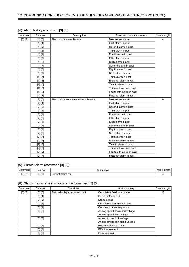
12. COMMUNICATION FUNCTION (MITSUBISHI GENERAL-PURPOSE AC SERVO PROTOCOL)
12 - 11
(4) Alarm history (command [3] [3]) Command Data No. Description Alarm occurrence sequence Frame length
[3] [3] [1] [0] Alarm No. in alarm history Most recent alarm 4
[1] [1] First alarm in past
[1] [2] Second alarm in past
[1] [3] Third alarm in past
[1] [4] Fourth alarm in past
[1] [5] Fifth alarm in past
[1] [6] Sixth alarm in past
[1] [7] Seventh alarm in past
[1] [8] Eighth alarm in past
[1] [9] Ninth alarm in past
[1] [A] Tenth alarm in past
[1] [B] Eleventh alarm in past
[1] [C] Twelfth alarm in past
[1] [D] Thirteenth alarm in past
[1] [E] Fourteenth alarm in past
[1] [F] Fifteenth alarm in past
[2] [0] Alarm occurrence time in alarm history Most recent alarm 8
[2] [1] First alarm in past
[2] [2] Second alarm in past
[2] [3] Third alarm in past
[2] [4] Fourth alarm in past
[2] [5] Fifth alarm in past
[2] [6] Sixth alarm in past
[2] [7] Seventh alarm in past
[2] [8] Eighth alarm in past
[2] [9] Ninth alarm in past
[2] [A] Tenth alarm in past
[2] [B] Eleventh alarm in past
[2] [C] Twelfth alarm in past
[2] [D] Thirteenth alarm in past
[2] [E] Fourteenth alarm in past
[2] [F] Fifteenth alarm in past
(5) Current alarm (command [0] [2]) Command Data No. Description Frame length
[0] [2] [0] [0] Current alarm No. 4
(6) Status display at alarm occurrence (command [3] [5]) Command Data No. Description Status display Frame length
[3] [5] [0] [0] Status display symbol and unit Cumulative feedback pulses 16
[0] [1] Servo motor speed
[0] [2] Droop pulses
[0] [3] Cumulative command pulses
[0] [4] Command pulse frequency
[0] [5] Analog speed command voltage Analog speed limit voltage
[0] [6] Analog torque limit voltage Analog torque command voltage
[0] [7] Regenerative load ratio
[0] [8] Effective load ratio
[0] [9] Peak load ratio
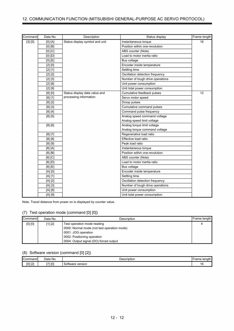
12. COMMUNICATION FUNCTION (MITSUBISHI GENERAL-PURPOSE AC SERVO PROTOCOL)
12 - 12
Command Data No. Description Status display Frame length
[3] [5] [0] [A] Status display symbol and unit Instantaneous torque 16
[0] [B] Position within one-revolution
[0] [C] ABS counter (Note)
[0] [D] Load to motor inertia ratio
[0] [E] Bus voltage
[2] [0] Encoder inside temperature
[2] [1] Settling time
[2] [2] Oscillation detection frequency
[2] [3] Number of tough drive operations
[2] [8] Unit power consumption
[2] [9] Unit total power consumption
[8] [0] Status display data value and processing information
Cumulative feedback pulses 12
[8] [1] Servo motor speed
[8] [2] Droop pulses
[8] [3] Cumulative command pulses
[8] [4] Command pulse frequency
[8] [5] Analog speed command voltage Analog speed limit voltage
[8] [6] Analog torque limit voltage Analog torque command voltage
[8] [7] Regenerative load ratio
[8] [8] Effective load ratio
[8] [9] Peak load ratio
[8] [A] Instantaneous torque
[8] [B] Position within one-revolution
[8] [C] ABS counter (Note)
[8] [D] Load to motor inertia ratio
[8] [E] Bus voltage
[A] [0] Encoder inside temperature
[A] [1] Settling time
[A] [2] Oscillation detection frequency
[A] [3] Number of tough drive operations
[A] [8] Unit power consumption
[A] [9] Unit total power consumption Note. Travel distance from power on is displayed by counter value.
(7) Test operation mode (command [0] [0]) Command Data No. Description Frame length
[0] [0] [1] [2] Test operation mode reading 0000: Normal mode (not test operation mode) 0001: JOG operation 0002: Positioning operation 0004: Output signal (DO) forced output
4
(8) Software version (command [0] [2]) Command Data No. Description Frame length
[0] [2] [7] [0] Software version 16

12. COMMUNICATION FUNCTION (MITSUBISHI GENERAL-PURPOSE AC SERVO PROTOCOL)
12 - 13
12.4.2 Writing commands
(1) Status display (command [8] [1]) Command Data No. Description Setting range Frame length
[8] [1] [0] [0] Status display data deletion 1EA5 4
(2) Parameters (command [9] [4], [8] [5]) Command Data No. Description Setting range Frame length
[9] [4] [0] [1] to [F] [F] Writing each parameter Writes the values of the parameters in the parameter group specified with the command [8] [5] + data No. [0] [0]. Before writing the values, therefore, always specify the parameter group with the command [8] [5] + data No. [0] [0]. The decimal equivalent of the data No. value (hexadecimal) corresponds to the parameter No.
Depending on the parameter
12
[8] [5] [0] [0] Parameter group writing 0000: Basic setting parameters ([Pr. PA_ _ ]) 0001: Gain/filter parameters ([Pr. PB_ _ ]) 0002: Extension setting parameters ([Pr. PC_ _ ]) 0003: I/O setting parameters ([Pr. PD_ _ ]) 0004: Extension setting 2 parameters ([Pr. PE_ _ ]) 0005: Extension setting 3 parameters ([Pr. PF_ _ ])
0000 to 0005 4
(3) External I/O signals (command [9] [2]) Command Data No. Description Setting range Frame length
[9] [2] [6] [0] Communication input device signal Refer to section 12.5.5.
8
(4) Alarm history (command [8] [2]) Command Data No. Description Setting range Frame length
[8] [2] [2] [0] Alarm history clear 1EA5 4
(5) Current alarm (command [8] [2]) Command Data No. Description Setting range Frame length
[8] [2] [0] [0] Alarm clear 1EA5 4
(6) I/O device prohibition (command [9] [0]) Command Data No. Description Setting range Frame length
[9] [0] [0] [0] Turns off the input device, external analog input signal or pulse train input, except EM2, LSP and LSN, independently of the external on/off status.
1EA5 4
[0] [3] Disables all output devices (DO). 1EA5 4
[1] [0] Cancels the prohibition of the input device, external analog input signal or pulse train input, except EM2, LSP and LSN.
1EA5 4
[1] [3] Cancels the prohibition of the output device. 1EA5 4
(7) Operation mode selection (command [8] [B]) Command Data No. Description Setting range Frame length
[8] [B] [0] [0] Selection of test operation mode 0000: Test operation mode cancel 0001: JOG operation 0002: Positioning operation 0004: Output signal (DO) forced output
0000 to 0002, 0004 4
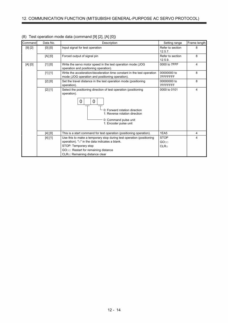
12. COMMUNICATION FUNCTION (MITSUBISHI GENERAL-PURPOSE AC SERVO PROTOCOL)
12 - 14
(8) Test operation mode data (command [9] [2], [A] [0]) Command Data No. Description Setting range Frame length
[9] [2] [0] [0] Input signal for test operation Refer to section 12.5.7.
8
[A] [0] Forced output of signal pin Refer to section 12.5.9.
8
[A] [0] [1] [0] Write the servo motor speed in the test operation mode (JOG operation and positioning operation).
0000 to 7FFF 4
[1] [1] Write the acceleration/deceleration time constant in the test operation mode (JOG operation and positioning operation).
00000000 to 7FFFFFFF
8
[2] [0] Set the travel distance in the test operation mode (positioning operation).
00000000 to 7FFFFFFF
8
[2] [1] Select the positioning direction of test operation (positioning operation).
0: Forward rotation direction1: Reverse rotation direction
0: Command pulse unit1: Encoder pulse unit
0 0
0000 to 0101 4
[4] [0] This is a start command for test operation (positioning operation). 1EA5 4
[4] [1] Use this to make a temporary stop during test operation (positioning operation). "" in the data indicates a blank. STOP: Temporary stop GO: Restart for remaining distance CLR: Remaining distance clear
STOP GO CLR
4

12. COMMUNICATION FUNCTION (MITSUBISHI GENERAL-PURPOSE AC SERVO PROTOCOL)
12 - 15
12.5 Detailed explanations of commands
12.5.1 Data processing
When the master station transmits a command data No. or a command + data No. + data to a slave station,
the servo amplifier returns a response or data in accordance with the purpose.
When numerical values are represented in these send data and receive data, they are represented in
decimal, hexadecimal, etc.
Therefore, data must be processed in accordance with the application.
Since whether data must be processed or not and how to process data depend on the monitoring,
parameters, etc., follow the detailed explanation of the corresponding command.
The following methods are how to process send and receive data when reading and writing data.
(1) Processing a read data
When the display type is 0, convert the eight-character data from hexadecimal to decimal, and place a
decimal point according to the decimal point information.
When the display type is 1, use the eight-character data unchanged.
The following example indicates how to process the receive data "003000000929" given to show.
The receive data is as follows.
0 0 3 0 0 0 0 0 0 9 2 9
Display type0: Data must be converted into decimal.1: Data is used unchanged in hexadecimal.
Decimal point position0: No decimal point1: First least significant digit (normally not used)2: Second least significant digit3: Third least significant digit4: Forth least significant digit5: Fifth least significant digit6: Sixth least significant digit
Data 32-bit length (hexadecimal representation)(Data conversion is required as indicated in the display type.)
Since the display type is "0" in this case, convert the hexadecimal data to decimal.
00000929H → 2345
As the decimal point position is "3", place a decimal point in the lower third digit.
Hence, "23.45" is displayed.

12. COMMUNICATION FUNCTION (MITSUBISHI GENERAL-PURPOSE AC SERVO PROTOCOL)
12 - 16
(2) Writing processed data
When the data to be written is handled as decimal, the decimal point position must be specified. If it is
not specified, the data cannot be written. When the data is handled as hexadecimal, specify "0" as the
decimal point position.
The data to be sent is the following value.
Decimal point position0: No decimal point1: First least significant digit2: Second least significant digit3: Third least significant digit4: Forth least significant digit5: Fifth least significant digit
0Data is transferred in hexadecimal.
For example, here is described how to process the set data when a value of "15.5" is sent.
Since the decimal point position is the second least significant digit, the decimal point position data is
"2".
As the data to be sent is hexadecimal, convert the decimal data into hexadecimal.
155 → 9B
Hence, "0200009B" is transmitted.

12. COMMUNICATION FUNCTION (MITSUBISHI GENERAL-PURPOSE AC SERVO PROTOCOL)
12 - 17
12.5.2 Status display mode
(1) Reading the status display name and unit
The following shows how to read the status display name and unit.
(a) Transmission
Transmit the command [0] [1] and the data No. corresponding to the status display item to be read,
[0] [0] to [0] [E] and [2] [0] to [2] [9]. (Refer to section 12.4.1.)
(b) Return
The slave station returns the status display name and unit requested.
0 0Unit characters (5 digits) Name characters (9 digits)
(2) Status display data reading
The following shows how to read the status display data and processing information.
(a) Transmission
Transmit the command [0] [1] and the data No. corresponding to the status display item to be read,
[8] [0] to [8] [E] and [A] [0] to [A] [9]. (Refer to section 12.4.1.)
(b) Return
The slave station returns the status display data requested.
Display type0: Data must be converted into decimal.1: Data is used unchanged in hexadecimal.
Decimal point position0: No decimal point1: First least significant digit (normally not used)2: Second least significant digit3: Third least significant digit4: Forth least significant digit5: Fifth least significant digit6: Sixth least significant digit
Data 32-bit length (hexadecimal representation)(Data conversion is required as indicated in the display type.)
0 0
(3) Status display data clear
To clear the cumulative feedback pulse data of the status display, send this command immediately after
reading the status display item. The data of the status display item transmitted is cleared to "0".
Command Data No. Data
[8] [1] [0] [0] 1EA5
For example, after sending command [0] [1] and data No. [8] [0] and receiving the status display data,
send command [8] [1], data No. [0] [0] and data [1EA5] to clear the cumulative feedback pulse value to
"0".
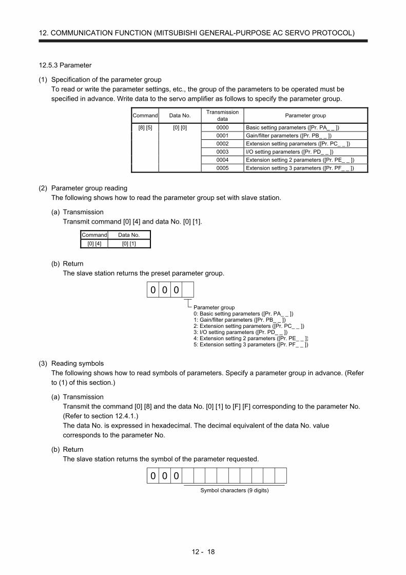
12. COMMUNICATION FUNCTION (MITSUBISHI GENERAL-PURPOSE AC SERVO PROTOCOL)
12 - 18
12.5.3 Parameter
(1) Specification of the parameter group
To read or write the parameter settings, etc., the group of the parameters to be operated must be
specified in advance. Write data to the servo amplifier as follows to specify the parameter group.
Command Data No. Transmission
data Parameter group
[8] [5] [0] [0] 0000 Basic setting parameters ([Pr. PA_ _ ])
0001 Gain/filter parameters ([Pr. PB_ _ ])
0002 Extension setting parameters ([Pr. PC_ _ ])
0003 I/O setting parameters ([Pr. PD_ _ ])
0004 Extension setting 2 parameters ([Pr. PE_ _ ])
0005 Extension setting 3 parameters ([Pr. PF_ _ ])
(2) Parameter group reading
The following shows how to read the parameter group set with slave station.
(a) Transmission
Transmit command [0] [4] and data No. [0] [1].
Command Data No.
[0] [4] [0] [1]
(b) Return
The slave station returns the preset parameter group.
0 0
Parameter group0: Basic setting parameters ([Pr. PA_ _ ])1: Gain/filter parameters ([Pr. PB_ _ ])2: Extension setting parameters ([Pr. PC_ _ ])3: I/O setting parameters ([Pr. PD_ _ ])4: Extension setting 2 parameters ([Pr. PE_ _ ])5: Extension setting 3 parameters ([Pr. PF_ _ ])
0
(3) Reading symbols
The following shows how to read symbols of parameters. Specify a parameter group in advance. (Refer
to (1) of this section.)
(a) Transmission
Transmit the command [0] [8] and the data No. [0] [1] to [F] [F] corresponding to the parameter No.
(Refer to section 12.4.1.)
The data No. is expressed in hexadecimal. The decimal equivalent of the data No. value
corresponds to the parameter No.
(b) Return
The slave station returns the symbol of the parameter requested.
0 0 0Symbol characters (9 digits)

12. COMMUNICATION FUNCTION (MITSUBISHI GENERAL-PURPOSE AC SERVO PROTOCOL)
12 - 19
(4) Reading the setting
The following shows how to read the parameter setting. Specify a parameter group in advance. (Refer to
(1) of this section.)
(a) Transmission
Transmit the command [1] [5] and the data No. corresponding to the parameter No [0] [1] to [F] [F].
(Refer to section 12.4.1.)
The data No. is expressed in hexadecimal. The decimal equivalent of the data No. value
corresponds to the parameter No.
(b) Return
The slave station returns the data and processing information of the parameter No. requested.
0 0
Display type0: Data is used unchanged in hexadecimal.1: Data must be converted into decimal.
Parameter writing type0: Enabled after writing1: Enabled when power is cycled after writing
Decimal point position0: No decimal point1: First least significant digit2: Second least significant digit3: Third least significant digit4: Forth least significant digit5: Fifth least significant digit
Data is transferred in hexadecimal.
0 0 0
Sign0: Sign1: No sign
0
For example, data "00120000270F" means 999.9 (decimal display format) and data
"000000003ABC" means 3ABC (hexadecimal display format).
When the display type is "0" (hexadecimal) and the decimal point position is other than 0, the display
type is a special hexadecimal display format and "F" of the data value is handled as a blank. Data
"0001FFFFF053" means 053 (special hexadecimal display format).
"000000000000" is transferred when the parameter that was read is the one inaccessible for
writing/reference in the parameter writing inhibit setting of [Pr. PA19].

12. COMMUNICATION FUNCTION (MITSUBISHI GENERAL-PURPOSE AC SERVO PROTOCOL)
12 - 20
(5) Reading the setting range
The following shows how to read the parameter setting range. Specify a parameter group in advance.
(Refer to (1) of this section.)
(a) Transmission
When reading an upper limit value, transmit the command [1] [6] and the data No. [0] [1] to [F] [F]
corresponding to the parameter No. When reading an lower limit value, transmit the command [1] [7]
and the data No. [0] [1] to [F] [F] corresponding to the parameter No. (Refer to section 12.4.1.)
The data No. is expressed in hexadecimal. The decimal equivalent of the data No. value
corresponds to the parameter No.
(b) Return
The slave station returns the data and processing information of the parameter No. requested.
Data is transferred in hexadecimal.
For example, data "FFFFFFEC" means "-20".
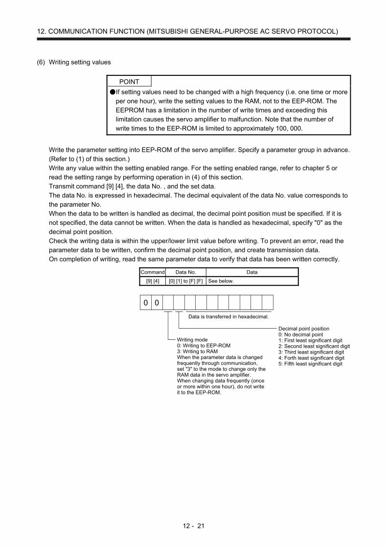
12. COMMUNICATION FUNCTION (MITSUBISHI GENERAL-PURPOSE AC SERVO PROTOCOL)
12 - 21
(6) Writing setting values
POINT
If setting values need to be changed with a high frequency (i.e. one time or more
per one hour), write the setting values to the RAM, not to the EEP-ROM. The
EEPROM has a limitation in the number of write times and exceeding this
limitation causes the servo amplifier to malfunction. Note that the number of
write times to the EEP-ROM is limited to approximately 100, 000.
Write the parameter setting into EEP-ROM of the servo amplifier. Specify a parameter group in advance.
(Refer to (1) of this section.)
Write any value within the setting enabled range. For the setting enabled range, refer to chapter 5 or
read the setting range by performing operation in (4) of this section.
Transmit command [9] [4], the data No. , and the set data.
The data No. is expressed in hexadecimal. The decimal equivalent of the data No. value corresponds to
the parameter No.
When the data to be written is handled as decimal, the decimal point position must be specified. If it is
not specified, the data cannot be written. When the data is handled as hexadecimal, specify "0" as the
decimal point position.
Check the writing data is within the upper/lower limit value before writing. To prevent an error, read the
parameter data to be written, confirm the decimal point position, and create transmission data.
On completion of writing, read the same parameter data to verify that data has been written correctly.
Command Data No. Data
[9] [4] [0] [1] to [F] [F] See below.
Writing mode0: Writing to EEP-ROM3: Writing to RAMWhen the parameter data is changedfrequently through communication,set "3" to the mode to change only theRAM data in the servo amplifier.When changing data frequently (onceor more within one hour), do not writeit to the EEP-ROM.
Decimal point position0: No decimal point1: First least significant digit2: Second least significant digit3: Third least significant digit4: Forth least significant digit5: Fifth least significant digit
Data is transferred in hexadecimal.
0 0
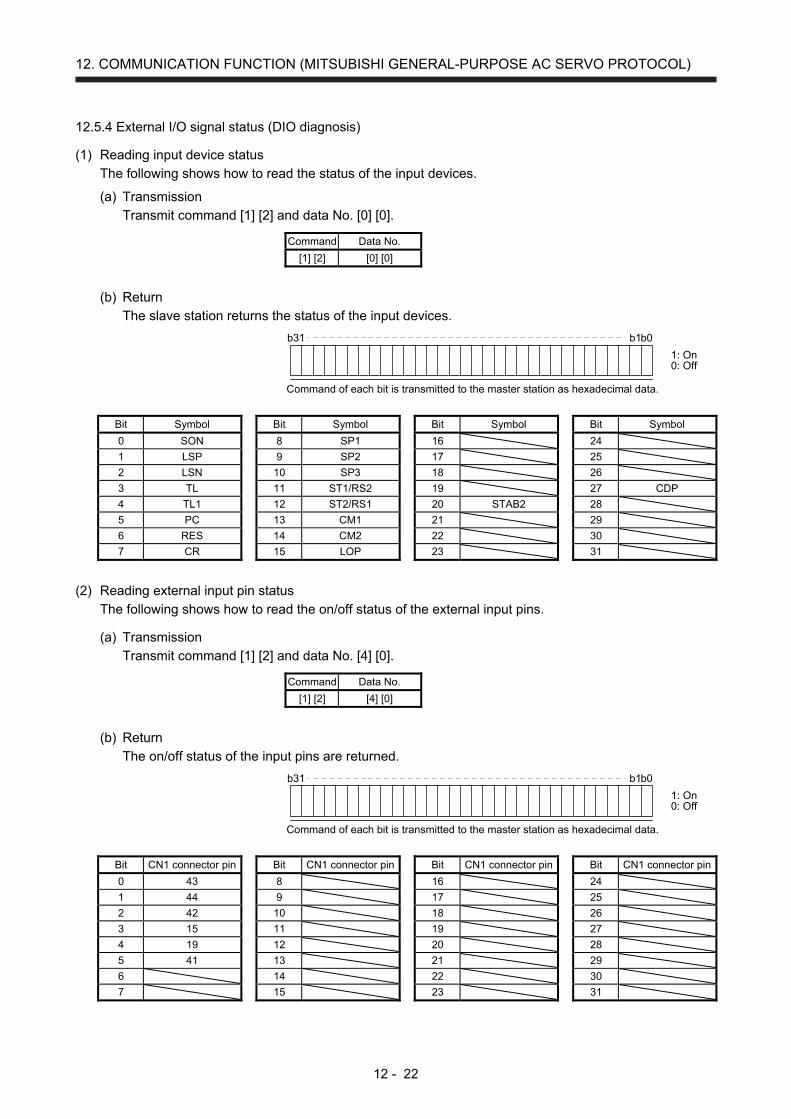
12. COMMUNICATION FUNCTION (MITSUBISHI GENERAL-PURPOSE AC SERVO PROTOCOL)
12 - 22
12.5.4 External I/O signal status (DIO diagnosis)
(1) Reading input device status
The following shows how to read the status of the input devices.
(a) Transmission
Transmit command [1] [2] and data No. [0] [0].
Command Data No.
[1] [2] [0] [0]
(b) Return
The slave station returns the status of the input devices.
b31 b1b0
1: On0: Off
Command of each bit is transmitted to the master station as hexadecimal data.
Bit Symbol Bit Symbol Bit Symbol Bit Symbol
0 SON 8 SP1 16 24
1 LSP 9 SP2 17 25
2 LSN 10 SP3 18 26
3 TL 11 ST1/RS2 19 27 CDP
4 TL1 12 ST2/RS1 20 STAB2 28
5 PC 13 CM1 21 29
6 RES 14 CM2 22 30
7 CR 15 LOP 23 31
(2) Reading external input pin status
The following shows how to read the on/off status of the external input pins.
(a) Transmission
Transmit command [1] [2] and data No. [4] [0].
Command Data No.
[1] [2] [4] [0]
(b) Return
The on/off status of the input pins are returned.
b31 b1b0
1: On0: Off
Command of each bit is transmitted to the master station as hexadecimal data.
Bit CN1 connector pin Bit CN1 connector pin Bit CN1 connector pin Bit CN1 connector pin
0 43 8 16 24
1 44 9 17 25
2 42 10 18 26
3 15 11 19 27
4 19 12 20 28
5 41 13 21 29
6 14 22 30
7 15 23 31

12. COMMUNICATION FUNCTION (MITSUBISHI GENERAL-PURPOSE AC SERVO PROTOCOL)
12 - 23
(3) Reading the status of input devices switched on with communication
The following shows how to read the on/off status of the input devices switched on with communication.
(a) Transmission
Transmit command [1] [2] and data No. [6] [0].
Command Data No.
[1] [2] [6] [0]
(b) Return
The slave station returns the status of the input devices.
b31 b1b0
1: On0: Off
Command of each bit is transmitted to the master station as hexadecimal data.
Bit Symbol Bit Symbol Bit Symbol Bit Symbol
0 SON 8 SP1 16 24
1 LSP 9 SP2 17 25
2 LSN 10 SP3 18 26
3 TL 11 ST1/RS2 19 27 CDP
4 TL1 12 ST2/RS1 20 STAB2 28
5 PC 13 CM1 21 29
6 RES 14 CM2 22 30
7 CR 15 LOP 23 31
(4) Reading output device status
The following shows how to read the on/off status of the output devices.
(a) Transmission
Transmit command [1] [2] and data No. [8] [0].
Command Data No.
[1] [2] [8] [0]
(b) Return
The slave station returns the status of the input/output devices.
b31 b1b0
1: On0: Off
Command of each bit is transmitted to the master station as hexadecimal data.
Bit Symbol Bit Symbol Bit Symbol Bit Symbol
0 RD 8 ALM 16 24
1 SA 9 OP 17 25 CDPS
2 ZSP 10 MBR 18 26
3 TLC 11 19 27
4 VLC 12 ACD0 20 28
5 INP 13 ACD1 21 29
6 14 ACD2 22 30
7 WNG 15 23 31 MTTR
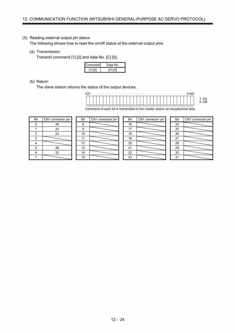
12. COMMUNICATION FUNCTION (MITSUBISHI GENERAL-PURPOSE AC SERVO PROTOCOL)
12 - 24
(5) Reading external output pin status
The following shows how to read the on/off status of the external output pins.
(a) Transmission
Transmit command [1] [2] and data No. [C] [0].
Command Data No.
[1] [2] [C] [0]
(b) Return
The slave station returns the status of the output devices.
b31 b1b0
1: On0: Off
Command of each bit is transmitted to the master station as hexadecimal data.
Bit CN1 connector pin Bit CN1 connector pin Bit CN1 connector pin Bit CN1 connector pin
0 49 8 16 24
1 24 9 17 25
2 23 10 18 26
3 11 19 27
4 12 20 28
5 48 13 21 29
6 33 14 22 30
7 15 23 31
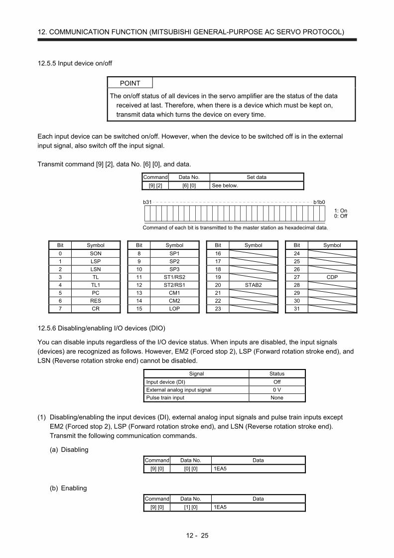
12. COMMUNICATION FUNCTION (MITSUBISHI GENERAL-PURPOSE AC SERVO PROTOCOL)
12 - 25
12.5.5 Input device on/off
POINT The on/off status of all devices in the servo amplifier are the status of the data
received at last. Therefore, when there is a device which must be kept on,
transmit data which turns the device on every time.
Each input device can be switched on/off. However, when the device to be switched off is in the external
input signal, also switch off the input signal.
Transmit command [9] [2], data No. [6] [0], and data.
Command Data No. Set data
[9] [2] [6] [0] See below.
b31 b1b0
1: On0: Off
Command of each bit is transmitted to the master station as hexadecimal data.
Bit Symbol Bit Symbol Bit Symbol Bit Symbol
0 SON 8 SP1 16 24
1 LSP 9 SP2 17 25
2 LSN 10 SP3 18 26
3 TL 11 ST1/RS2 19 27 CDP
4 TL1 12 ST2/RS1 20 STAB2 28
5 PC 13 CM1 21 29
6 RES 14 CM2 22 30
7 CR 15 LOP 23 31
12.5.6 Disabling/enabling I/O devices (DIO)
You can disable inputs regardless of the I/O device status. When inputs are disabled, the input signals
(devices) are recognized as follows. However, EM2 (Forced stop 2), LSP (Forward rotation stroke end), and
LSN (Reverse rotation stroke end) cannot be disabled.
Signal Status
Input device (DI) Off
External analog input signal 0 V
Pulse train input None
(1) Disabling/enabling the input devices (DI), external analog input signals and pulse train inputs except
EM2 (Forced stop 2), LSP (Forward rotation stroke end), and LSN (Reverse rotation stroke end).
Transmit the following communication commands.
(a) Disabling
Command Data No. Data
[9] [0] [0] [0] 1EA5
(b) Enabling
Command Data No. Data
[9] [0] [1] [0] 1EA5
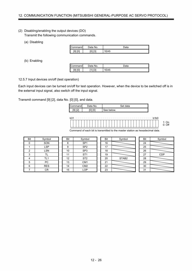
12. COMMUNICATION FUNCTION (MITSUBISHI GENERAL-PURPOSE AC SERVO PROTOCOL)
12 - 26
(2) Disabling/enabling the output devices (DO)
Transmit the following communication commands.
(a) Disabling
Command Data No. Data
[9] [0] [0] [3] 1EA5
(b) Enabling
Command Data No. Data
[9] [0] [1] [3] 1EA5
12.5.7 Input devices on/off (test operation)
Each input devices can be turned on/off for test operation. However, when the device to be switched off is in
the external input signal, also switch off the input signal.
Transmit command [9] [2], data No. [0] [0], and data.
Command Data No. Set data
[9] [2] [0] [0] See below.
b31 b1b0
1: On0: Off
Command of each bit is transmitted to the master station as hexadecimal data.
Bit Symbol Bit Symbol Bit Symbol Bit Symbol
0 SON 8 SP1 16 24
1 LSP 9 SP2 17 25
2 LSN 10 SP3 18 26
3 TL 11 ST1 19 27 CDP
4 TL1 12 ST2 20 STAB2 28
5 PC 13 CM1 21 29
6 RES 14 CM2 22 30
7 CR 15 LOP 23 31

12. COMMUNICATION FUNCTION (MITSUBISHI GENERAL-PURPOSE AC SERVO PROTOCOL)
12 - 27
12.5.8 Test operation mode
POINT
The test operation mode is used to check operation. Do not use it for actual
operation.
If communication stops for longer than 0.5 s during test operation, the servo
amplifier decelerates to a stop, resulting in servo-lock. To prevent this, continue
communication all the time by monitoring the status display, etc.
Even during operation, you can switch the servo amplifier to the test operation
mode. In this case, switching to the test operation mode will shut off the base
circuit to coast the motor.
(1) How to prepare and cancel the test operation mode
(a) Preparing the test operation mode
Set the test operation mode type with the following procedure.
1) Selection of test operation mode
Send the command [8] [B] + data No. [0] [0] + data to select the test operation mode.
Command Data No. Transmission
data Selection of test operation mode
[8] [B] [0] [0]
0001 JOG operation
0002 Positioning operation
0004 Output signal (DO) forced output (Note)
Note. Refer to section 12.5.9 for the output signal (DO) forced output.
2) Check of test operation mode
Read the test operation mode set for the slave station, and check that it is set correctly.
a) Transmission
Transmit command [0] [0] and data No. [1] [2].
Command Data No.
[0] [0] [1] [2]
b) Reply
The slave station returns the preset operation mode.
0 0
Test operation mode reading0: Normal mode (not test operation mode)1: JOG operation2: Positioning operation4: Output signal (DO) forced output
0
(b) Cancel of test operation mode
To terminate the test operation mode, send the command [8] [B] + data No. [0] [0] + data.
Command Data No. Transmission
data Selection of test operation mode
[8] [B] [0] [0] 0000 Test operation mode cancel
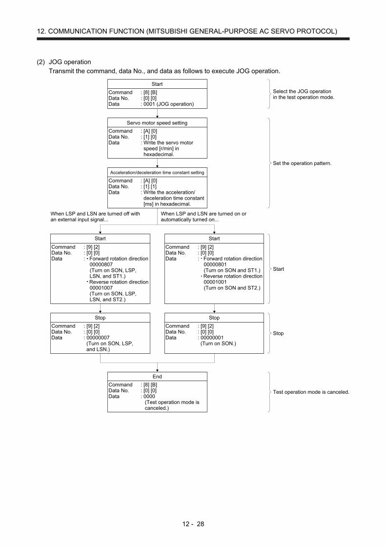
12. COMMUNICATION FUNCTION (MITSUBISHI GENERAL-PURPOSE AC SERVO PROTOCOL)
12 - 28
(2) JOG operation
Transmit the command, data No., and data as follows to execute JOG operation.
StartStart
Stop Stop
End
When LSP and LSN are turned off withan external input signal...
Acceleration/deceleration time constant setting
Command : [A] [0]Data No. : [1] [0]Data : Write the servo motor
speed [r/min] inhexadecimal.
Command : [A] [0]Data No. : [1] [1]Data : Write the acceleration/
deceleration time constant[ms] in hexadecimal.
Servo motor speed setting
Select the JOG operationin the test operation mode.
Set the operation pattern.
Start
Stop
Test operation mode is canceled.
Command : [8] [B]Data No. : [0] [0]Data : 0001 (JOG operation)
Start
Command : [9] [2]Data No. : [0] [0]Data : Forward rotation direction
00000807(Turn on SON, LSP,LSN, and ST1.)
Reverse rotation direction00001007(Turn on SON, LSP,LSN, and ST2.)
Command : [9] [2]Data No. : [0] [0]Data : Forward rotation direction
00000801(Turn on SON and ST1.)
Reverse rotation direction00001001(Turn on SON and ST2.)
Command : [9] [2]Data No. : [0] [0]Data : 00000007
(Turn on SON, LSP,and LSN.)
Command : [9] [2]Data No. : [0] [0]Data : 00000001
(Turn on SON.)
Command : [8] [B]Data No. : [0] [0]Data : 0000
(Test operation mode iscanceled.)
When LSP and LSN are turned on orautomatically turned on...
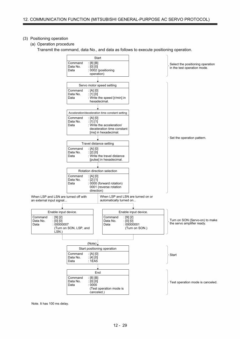
12. COMMUNICATION FUNCTION (MITSUBISHI GENERAL-PURPOSE AC SERVO PROTOCOL)
12 - 29
(3) Positioning operation
(a) Operation procedure
Transmit the command, data No., and data as follows to execute positioning operation.
Command : [8] [B]Data No. : [0] [0]Data : 0002 (positioning
operation)
Command : [9] [2]Data No. : [0] [0]Data : 00000007
(Turn on SON, LSP, andLSN.)
Command : [9] [2]Data No. : [0] [0]Data : 00000001
(Turn on SON.)
Enable input device. Enable input device.
Command : [A] [0]Data No. : [4] [0]Data : 1EA5
Start positioning operation
Command : [A] [0]Data No. : [1] [1]Data : Write the acceleration/
deceleration time constant[ms] in hexadecimal.
When LSP and LSN are turned off withan external input signal...
Acceleration/deceleration time constant setting
Command : [A] [0]Data No. : [1] [0]Data : Write the speed [r/min] in
hexadecimal.
Servo motor speed setting
Start
Select the positioning operationin the test operation mode.
Set the operation pattern.
Turn on SON (Servo-on) to makethe servo amplifier ready.
Command : [A] [0]Data No. : [2] [1]Data : 0000 (forward rotation)
0001 (reverse rotationdirection)
Rotation direction selection
Command : [A] [0]Data No. : [2] [0]Data : Write the travel distance
[pulse] in hexadecimal.
Travel distance setting
Command : [8] [B]Data No. : [0] [0]Data : 0000
(Test operation mode iscanceled.)
End
(Note)
Start
Test operation mode is canceled.
When LSP and LSN are turned on orautomatically turned on...
Note. It has 100 ms delay.
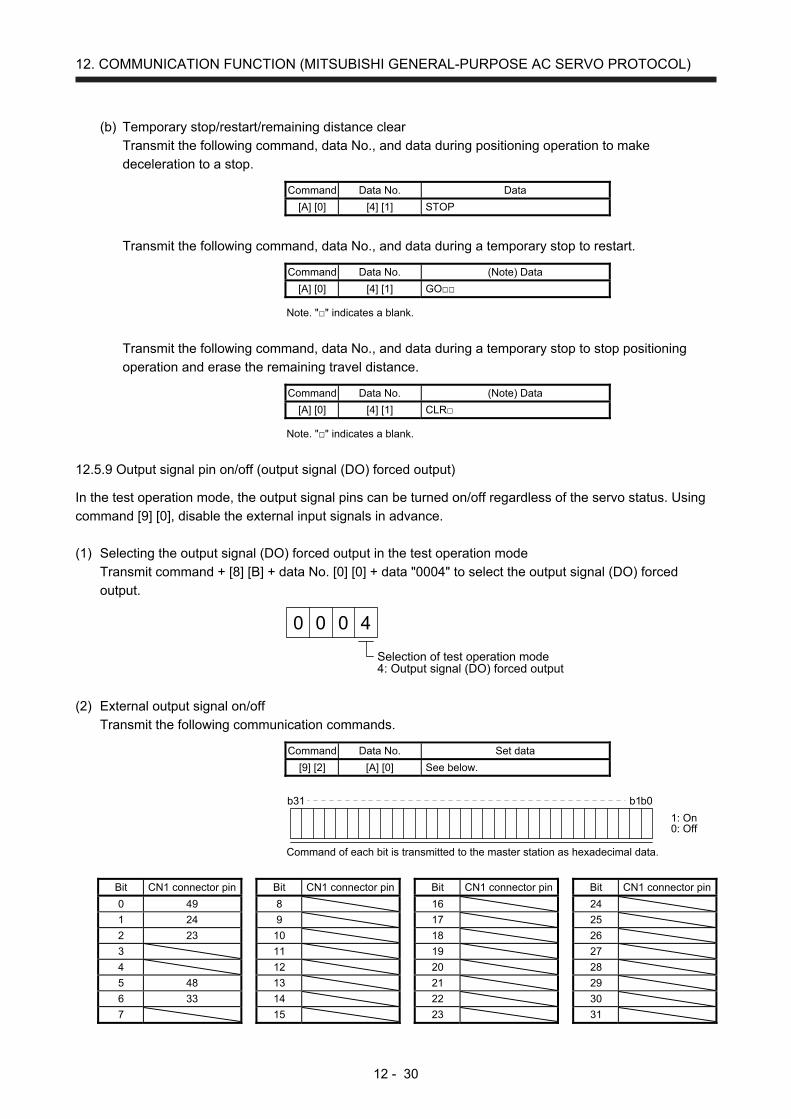
12. COMMUNICATION FUNCTION (MITSUBISHI GENERAL-PURPOSE AC SERVO PROTOCOL)
12 - 30
(b) Temporary stop/restart/remaining distance clear
Transmit the following command, data No., and data during positioning operation to make
deceleration to a stop.
Command Data No. Data
[A] [0] [4] [1] STOP
Transmit the following command, data No., and data during a temporary stop to restart.
Command Data No. (Note) Data
[A] [0] [4] [1] GO
Note. "" indicates a blank.
Transmit the following command, data No., and data during a temporary stop to stop positioning
operation and erase the remaining travel distance.
Command Data No. (Note) Data
[A] [0] [4] [1] CLR
Note. "" indicates a blank.
12.5.9 Output signal pin on/off (output signal (DO) forced output)
In the test operation mode, the output signal pins can be turned on/off regardless of the servo status. Using
command [9] [0], disable the external input signals in advance.
(1) Selecting the output signal (DO) forced output in the test operation mode
Transmit command + [8] [B] + data No. [0] [0] + data "0004" to select the output signal (DO) forced
output.
0 0 4
Selection of test operation mode4: Output signal (DO) forced output
0
(2) External output signal on/off
Transmit the following communication commands.
Command Data No. Set data
[9] [2] [A] [0] See below.
b31 b1b0
1: On0: Off
Command of each bit is transmitted to the master station as hexadecimal data.
Bit CN1 connector pin Bit CN1 connector pin Bit CN1 connector pin Bit CN1 connector pin
0 49 8 16 24
1 24 9 17 25
2 23 10 18 26
3 11 19 27
4 12 20 28
5 48 13 21 29
6 33 14 22 30
7 15 23 31

12. COMMUNICATION FUNCTION (MITSUBISHI GENERAL-PURPOSE AC SERVO PROTOCOL)
12 - 31
(3) Output signal (DO) forced output
Transmit command [8] [B] + data No. [0] [0] + data to stop the output signal (DO) forced output.
Command Data No. Transmission
data Selection of test operation mode
[8] [B] [0] [0] 0000 Test operation mode cancel
12.5.10 Alarm history
(1) Alarm No. reading
The following shows how to read alarm Nos. which occurred in the past. Alarm Nos. and occurrence
times of No. 0 (last alarm) to No. 15 (sixteenth alarm in the past) are read.
(a) Transmission
Transmit command [3] [3] + data No. [1] [0] to [1] [F]. Refer to section 12.4.1.
(b) Return
Alarm Nos. corresponding to the data No. is provided.
0 0
Alarm No. is transferred in hexadecimal.
For example, "0032" means [AL. 32] and "00FF" means [AL. _ _ ] (no alarm).
(2) Alarm occurrence time reading
The following shows how to read alarm occurrence times which occurred in the past.
Alarm occurrence time corresponding to the data No. is provided in terms of the total time beginning with
operation start, with the minute unit omitted.
(a) Transmission
Transmit command [3] [3] + data No. [2] [0] to [2] [F].
Refer to section 12.4.1.
(b) Return
The alarm occurrence time is transferred in hexadecimal.Hexadecimal must be converted into decimal.
For example, data "01F5" means that the alarm occurred in 501 hours after starting operation.
(3) Clearing the alarm history
Alarm history is cleared.
Transmit command [8] [2] and data No. [2] [0].
Command Data No. Data
[8] [2] [2] [0] 1EA5

12. COMMUNICATION FUNCTION (MITSUBISHI GENERAL-PURPOSE AC SERVO PROTOCOL)
12 - 32
12.5.11 Current alarm
(1) Current alarm reading
The following shows how to read the alarm No. which is occurring currently.
(a) Transmission
Transmit command [0] [2] and data No. [0] [0].
Command Data No.
[0] [2] [0] [0]
(b) Return
The slave station returns the alarm currently occurring.
0 0
Alarm No. is transferred in hexadecimal.
For example, "0032" means [AL. 32] and "00FF" means [AL. _ _ ] (no alarm).
(2) Reading status display at alarm occurrence
The following shows how to read the status display data at alarm occurrence. When the data No.
corresponding to the status display item is transmitted, the data value and data processing information
will be returned.
(a) Transmission
Transmit the command [3] [5] + the data No. corresponding to the status display item to read, [8] [0]
to [8] [E] and [A] [0] to [A] [9]. Refer to section 12.4.1.
(b) Return
The slave station returns the status display data of requested alarm at occurrence.
Display type0: Data must be converted into decimal.1: Data is used unchanged in hexadecimal.
Decimal point position0: No decimal point1: First least significant digit (normally not used)2: Second least significant digit3: Third least significant digit4: Forth least significant digit5: Fifth least significant digit6: Sixth least significant digit
Data 32-bit length (hexadecimal representation)(Data conversion is required as indicated in the display type.)
0 0
(3) Current alarm reset
As by the reset (RES) on, reset the servo amplifier alarm to make the servo amplifier ready to operate.
After removing the cause of the alarm, reset the alarm with no command entered.
Command Data No. Data
[8] [2] [0] [0] 1EA5
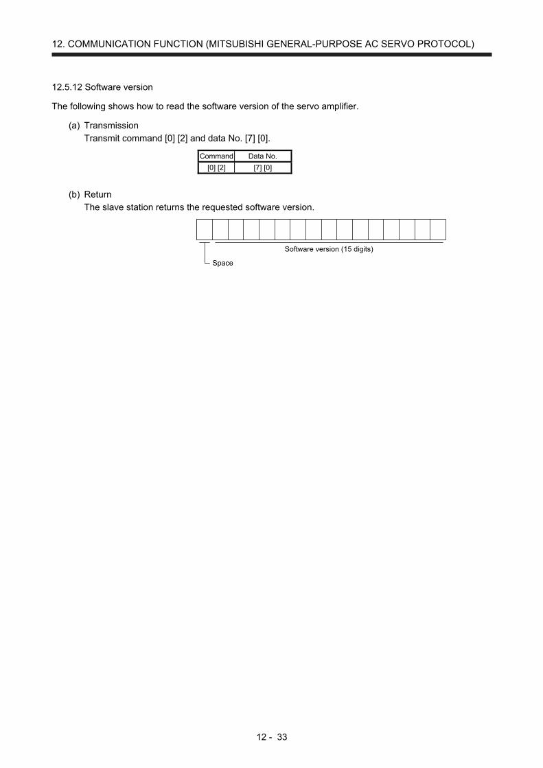
12. COMMUNICATION FUNCTION (MITSUBISHI GENERAL-PURPOSE AC SERVO PROTOCOL)
12 - 33
12.5.12 Software version
The following shows how to read the software version of the servo amplifier.
(a) Transmission
Transmit command [0] [2] and data No. [7] [0].
Command Data No.
[0] [2] [7] [0]
(b) Return
The slave station returns the requested software version.
Software version (15 digits)
Space

12. COMMUNICATION FUNCTION (MITSUBISHI GENERAL-PURPOSE AC SERVO PROTOCOL)
12 - 34
MEMO

APPENDIX
App. - 1
App. 1 Peripheral equipment manufacturer (for reference)
Names given in the table are as of Apr. 2015.
Manufacturer Contact information
JST J.S.T. Mfg. Co., Ltd.
3M 3M
Soshin Electric Soshin Electric Co., Ltd.
App. 2 Compliance with global standards
App. 2.1 About safety
This section explains safety of users and machine operators. Please read the section carefully before
mounting the equipment.
App. 2.1.1 Professional engineer
Only professional engineers should mount MR-JE servo amplifiers.
Here, professional engineers are persons who took a proper engineering training or qualified persons who
are engaged in electrical equipment.
Check if applicable technical training is available at your local Mitsubishi Electric office. Contact your local
sales office for schedules and locations.
App. 2.1.2 Applications of the devices
MR-JE servo amplifiers comply with the following standards.
IEC/EN 61800-5-1, IEC/EN 61800-3
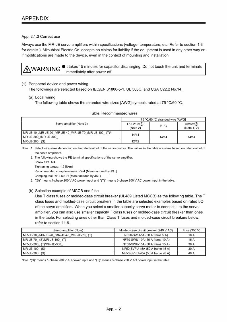
APPENDIX
App. - 2
App. 2.1.3 Correct use
Always use the MR-JE servo amplifiers within specifications (voltage, temperature, etc. Refer to section 1.3
for details.). Mitsubishi Electric Co. accepts no claims for liability if the equipment is used in any other way or
if modifications are made to the device, even in the context of mounting and installation.
WARNING It takes 15 minutes for capacitor discharging. Do not touch the unit and terminals
immediately after power off.
(1) Peripheral device and power wiring
The followings are selected based on IEC/EN 61800-5-1, UL 508C, and CSA C22.2 No.14.
(a) Local wiring
The following table shows the stranded wire sizes [AWG] symbols rated at 75 °C/60 °C.
Table. Recommended wires
Servo amplifier (Note 3) 75 °C/60 °C stranded wire [AWG]
L1/L2/L3/ (Note 2)
P+/C U/V/W/ (Note 1, 2)
MR-JE-10_/MR-JE-20_/MR-JE-40_/MR-JE-70_/MR-JE-100_ (T)/ MR-JE-200_/MR-JE-300_
14/14 14/14 14/14
MR-JE-200_ (S) 12/12 Note 1. Select wire sizes depending on the rated output of the servo motors. The values in the table are sizes based on rated output of
the servo amplifiers.
2. The following shows the PE terminal specifications of the servo amplifier.
Screw size: M4
Tightening torque: 1.2 [N•m]
Recommended crimp terminals: R2-4 (Manufactured by JST)
Crimping tool: YPT-60-21 (Manufactured by JST)
3. "(S)" means 1-phase 200 V AC power input and "(T)" means 3-phase 200 V AC power input in the table.
(b) Selection example of MCCB and fuse
Use T class fuses or molded-case circuit breaker (UL489 Listed MCCB) as the following table. The T
class fuses and molded-case circuit breakers in the table are selected examples based on rated I/O
of the servo amplifiers. When you select a smaller capacity servo motor to connect it to the servo
amplifier, you can also use smaller capacity T class fuses or molded-case circuit breaker than ones
in the table. For selecting ones other than Class T fuses and molded-case circuit breakers below,
refer to section 11.6.
Servo amplifier (Note) Molded-case circuit breaker (240 V AC) Fuse (300 V)
MR-JE-10_/MR-JE-20_/MR-JE-40_/MR-JE-70_ (T) NF50-SWU-5A (50 A frame 5 A) 10 A
MR-JE-70_ (S)/MR-JE-100_ (T) NF50-SWU-10A (50 A frame 10 A) 15 A
MR-JE-200_ (T)/MR-JE-300_ NF50-SWU-15A (50 A frame 15 A) 30 A
MR-JE-100_ (S) NF50-SVFU-15A (50 A frame 15 A) 30 A
MR-JE-200_ (S) NF50-SVFU-20A (50 A frame 20 A) 40 A Note. "(S)" means 1-phase 200 V AC power input and "(T)" means 3-phase 200 V AC power input in the table.
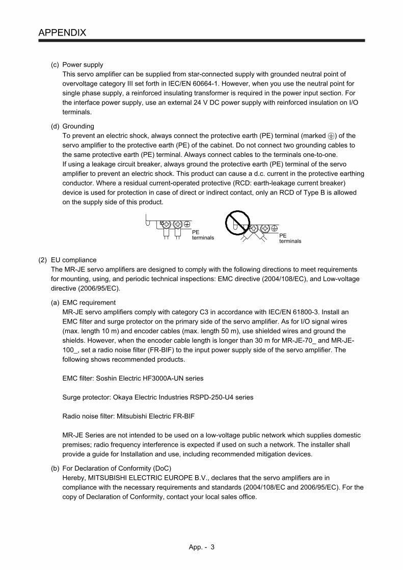
APPENDIX
App. - 3
(c) Power supply
This servo amplifier can be supplied from star-connected supply with grounded neutral point of
overvoltage category III set forth in IEC/EN 60664-1. However, when you use the neutral point for
single phase supply, a reinforced insulating transformer is required in the power input section. For
the interface power supply, use an external 24 V DC power supply with reinforced insulation on I/O
terminals.
(d) Grounding To prevent an electric shock, always connect the protective earth (PE) terminal (marked ) of the
servo amplifier to the protective earth (PE) of the cabinet. Do not connect two grounding cables to
the same protective earth (PE) terminal. Always connect cables to the terminals one-to-one.
If using a leakage circuit breaker, always ground the protective earth (PE) terminal of the servo
amplifier to prevent an electric shock. This product can cause a d.c. current in the protective earthing
conductor. Where a residual current-operated protective (RCD: earth-leakage current breaker)
device is used for protection in case of direct or indirect contact, only an RCD of Type B is allowed
on the supply side of this product.
PEterminals
PEterminals
(2) EU compliance
The MR-JE servo amplifiers are designed to comply with the following directions to meet requirements
for mounting, using, and periodic technical inspections: EMC directive (2004/108/EC), and Low-voltage
directive (2006/95/EC).
(a) EMC requirement
MR-JE servo amplifiers comply with category C3 in accordance with IEC/EN 61800-3. Install an
EMC filter and surge protector on the primary side of the servo amplifier. As for I/O signal wires
(max. length 10 m) and encoder cables (max. length 50 m), use shielded wires and ground the
shields. However, when the encoder cable length is longer than 30 m for MR-JE-70_ and MR-JE-
100_, set a radio noise filter (FR-BIF) to the input power supply side of the servo amplifier. The
following shows recommended products.
EMC filter: Soshin Electric HF3000A-UN series
Surge protector: Okaya Electric Industries RSPD-250-U4 series
Radio noise filter: Mitsubishi Electric FR-BIF
MR-JE Series are not intended to be used on a low-voltage public network which supplies domestic
premises; radio frequency interference is expected if used on such a network. The installer shall
provide a guide for Installation and use, including recommended mitigation devices.
(b) For Declaration of Conformity (DoC)
Hereby, MITSUBISHI ELECTRIC EUROPE B.V., declares that the servo amplifiers are in
compliance with the necessary requirements and standards (2004/108/EC and 2006/95/EC). For the
copy of Declaration of Conformity, contact your local sales office.
APPENDIX
App. - 4
(3) USA/Canada compliance
This servo amplifier is designed in compliance with UL 508C and CSA C22.2 No.14.
(a) Installation
The minimum cabinet size is 150% of MR-JE servo amplifier's volume. Also, design the cabinet so
that the ambient temperature in the cabinet is 55 °C or less. The servo amplifier must be installed in
the metal cabinet. Additionally, mount the servo amplifier on a cabinet that the protective earth based
on the standard of IEC/EN 60204-1 is correctly connected. For environment, the units should be
used in open type (UL 50) and overvoltage category shown in table in section 8.1. The servo
amplifier needs to be installed at or below of pollution degree 2. For connection, use copper wires.
(b) Short-circuit current rating (SCCR)
Suitable For Use On A Circuit Capable Of Delivering Not More Than 100 kA rms Symmetrical
Amperes, 500 Volts Maximum.
(c) Overload protection characteristics
The MR-JE servo amplifiers have solid-state servo motor overload protection. (It is set on the basis
(full load current) of 120% rated current of the servo amplifier.)
(d) Over-temperature protection for motor
Motor Over temperature sensing is not provided by the drive.
Integral thermal protection(s) is necessary for motor and refer to appendix. 4.3 for the proper
connection.
(e) Branch circuit protection
For installation in United States, branch circuit protection must be provided, in accordance with the
National Electrical Code and any applicable local codes.
For installation in Canada, branch circuit protection must be provided, in accordance with the
Canada Electrical Code and any applicable provincial codes.
(4) South Korea compliance
This product complies with the Radio Wave Law (KC mark). Please note the following to use the
product. 이 기기는 업무용 (A급) 전자파적합기기로서 판 매자 또는 사용자는 이 점을 주의하시기 바라며,
가정외의 지역에서 사용하는 것을 목적으 로 합니다.
(The product is for business use (Class A) and meets the electromagnetic compatibility requirements.
The seller and the user must note the above point, and use the product in a place except for home.)
App. 2.1.4 General cautions for safety protection and protective measures
Observe the following items to ensure proper use of the MELSERVO MR-JE servo amplifiers.
(1) For installing systems, only qualified personnel and professional engineers should perform.
(2) When mounting, installing, and using the MR-JE servo amplifier, always observe standards and
directives applicable in the country.
App. 2.1.5 Disposal
Disposal of unusable or irreparable devices should always occur in accordance with the applicable country-
specific waste disposal regulations. (Example: European Waste 16 02 14)
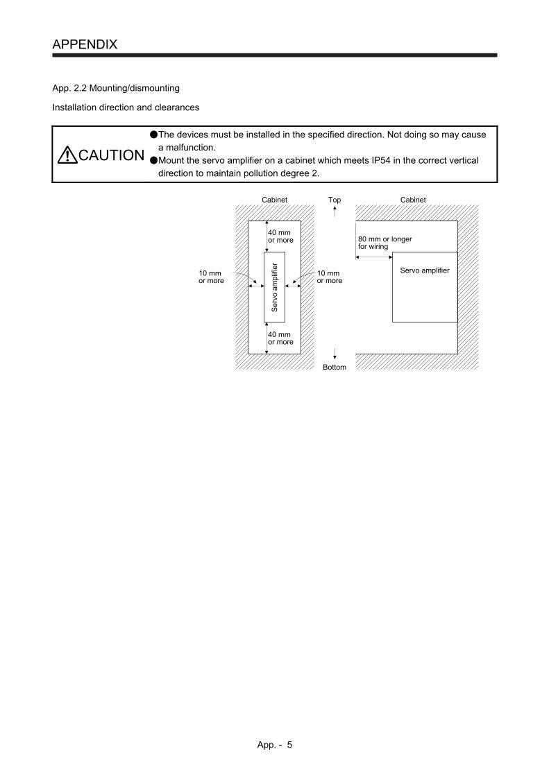
APPENDIX
App. - 5
App. 2.2 Mounting/dismounting
Installation direction and clearances
CAUTION
The devices must be installed in the specified direction. Not doing so may cause
a malfunction.
Mount the servo amplifier on a cabinet which meets IP54 in the correct vertical
direction to maintain pollution degree 2.
10 mmor more
80 mm or longerfor wiring
10 mmor more
Top
Bottom
40 mmor more
40 mmor more
Cabinet
Servo amplifierS
ervo
am
plifi
er
Cabinet
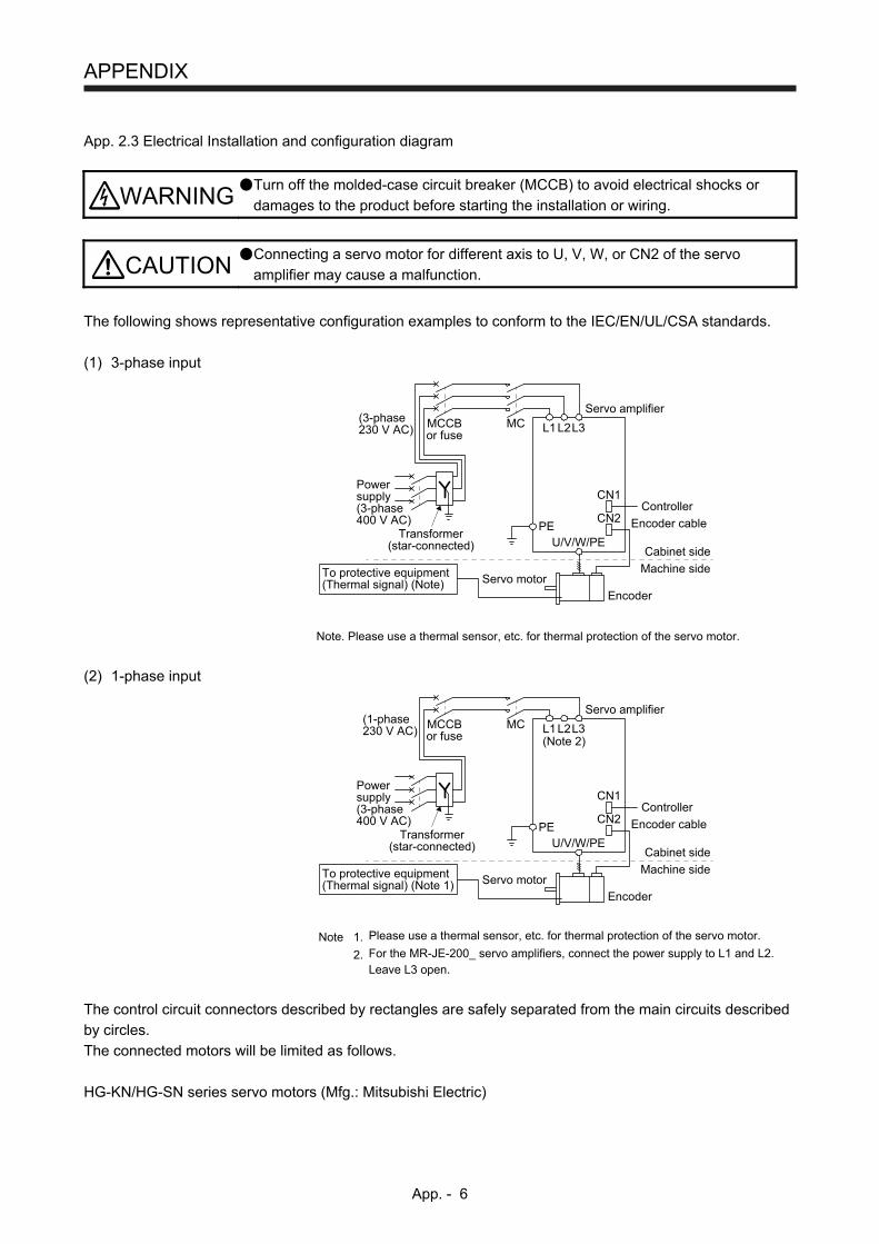
APPENDIX
App. - 6
App. 2.3 Electrical Installation and configuration diagram
WARNING Turn off the molded-case circuit breaker (MCCB) to avoid electrical shocks or
damages to the product before starting the installation or wiring.
CAUTION Connecting a servo motor for different axis to U, V, W, or CN2 of the servo
amplifier may cause a malfunction.
The following shows representative configuration examples to conform to the IEC/EN/UL/CSA standards.
(1) 3-phase input
MCCBor fuse
Controller
Encoder cable
(3-phase230 V AC)
Powersupply(3-phase400 V AC)
Transformer(star-connected)
PE
MCServo amplifier
Cabinet side
Machine side
Encoder
Servo motor
L1
U/V/W/PE
CN2
CN1
L2L3
To protective equipment(Thermal signal) (Note)
Note. Please use a thermal sensor, etc. for thermal protection of the servo motor.
(2) 1-phase input
MCCBor fuse
Controller
Encoder cable
(1-phase230 V AC)
Powersupply(3-phase400 V AC)
Transformer(star-connected)
PE
(Note 2)
MCServo amplifier
Cabinet side
Machine side
Encoder
Servo motor
L1
U/V/W/PE
CN2
CN1
L2L3
To protective equipment(Thermal signal) (Note 1)
Note 1. Please use a thermal sensor, etc. for thermal protection of the servo motor.
2. For the MR-JE-200_ servo amplifiers, connect the power supply to L1 and L2. Leave L3 open.
The control circuit connectors described by rectangles are safely separated from the main circuits described
by circles.
The connected motors will be limited as follows.
HG-KN/HG-SN series servo motors (Mfg.: Mitsubishi Electric)
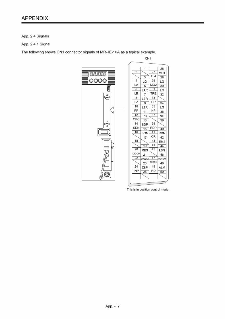
APPENDIX
App. - 7
App. 2.4 Signals
App. 2.4.1 Signal
The following shows CN1 connector signals of MR-JE-10A as a typical example.
1
3
5
7
9
11
13
15
17
19
21
23
25
2
4
6
8
10
12
14
16
18
20
22
24
TLAMO1
MO2
27
29
31
33
35
37
39
41
43
45
47
49
26
28
30
32
34
36
38
40
42
44
46
48
50
LGLA
LG
LARLB
LG
LBRLZ OP
LZR LG
EM2
DICOM
DICOMDOCOM
DOCOM
ALM
CN1
PP
OPCPG
SONCR
LSP
RES
ZSPRDINP
LSN
NP
NG
This is in position control mode.
TRE
SDNSDP
RDP
RDN
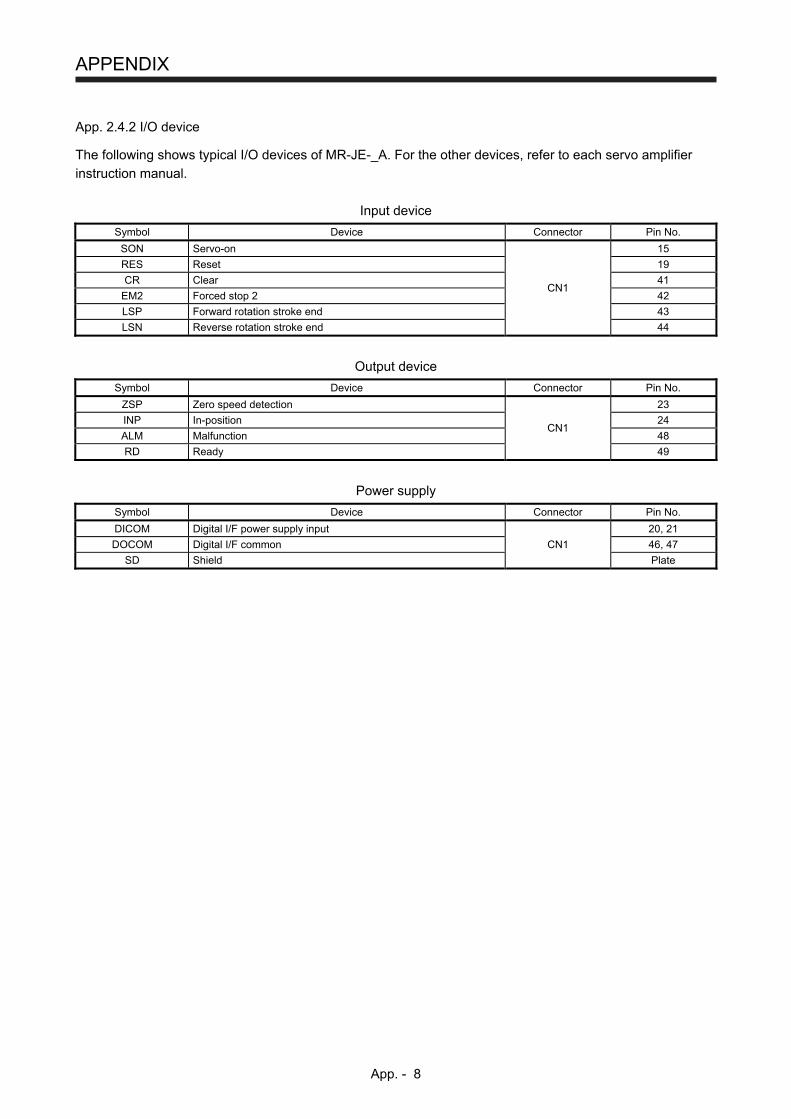
APPENDIX
App. - 8
App. 2.4.2 I/O device
The following shows typical I/O devices of MR-JE-_A. For the other devices, refer to each servo amplifier
instruction manual.
Input device
Symbol Device Connector Pin No.
SON Servo-on
CN1
15
RES Reset 19
CR Clear 41
EM2 Forced stop 2 42
LSP Forward rotation stroke end 43
LSN Reverse rotation stroke end 44
Output device
Symbol Device Connector Pin No.
ZSP Zero speed detection
CN1
23
INP In-position 24
ALM Malfunction 48
RD Ready 49
Power supply
Symbol Device Connector Pin No.
DICOM Digital I/F power supply input 20, 21
DOCOM Digital I/F common CN1 46, 47
SD Shield Plate

APPENDIX
App. - 9
App. 2.5 Maintenance and service
WARNING To avoid an electric shock, only qualified personnel should attempt inspections.
For repair and parts replacement, contact your local sales office.
App. 2.5.1 Inspection items
It is recommended that the following points periodically be checked.
(1) Check for loose screws on the protective earth (PE) terminal. Retighten any loose screws. (tightening
torque: 1.2 N•m)
(2) Servo motor bearings, brake section, etc. for unusual noise.
(3) Check the cables and the like for scratches or cracks. Perform periodic inspection according to
operating conditions.
(4) Check that the connectors are securely connected to the servo motor.
(5) Check that the wires are not coming out from the connector.
(6) Check for dust accumulation on the servo amplifier.
(7) Check for unusual noise generated from the servo amplifier.
(8) Check the servo motor shaft and coupling for connection.
App. 2.5.2 Parts having service lives
Service lives of the following parts are listed below. However, the service lives vary depending on operation
and environment. If any fault is found in the parts, they must be replaced immediately regardless of their
service lives. For parts replacement, please contact your local sales office.
Part name Life guideline
Smoothing capacitor (Note) 10 years
Relay Number of power-on, forced stop, and controller forced stop times:
100 000 times
Cooling fan 50,000 hours to 70,000 hours (7 years to 8 years) Note. The characteristic of smoothing capacitor is deteriorated due to ripple currents, etc. The life of the capacitor greatly depends on
ambient temperature and operating conditions. The capacitor will reach the end of its life in 10 years of continuous operation in
normal air-conditioned environment (40 °C surrounding air temperature or less).

APPENDIX
App. - 10
App. 2.6 Transportation and storage
CAUTION
Transport the products correctly according to their mass.
Stacking in excess of the limited number of product packages is not allowed.
Install the product in a load-bearing place of servo amplifier and servo motor in
accordance with instruction manual.
Do not get on or put heavy load on the equipment.
Do not hold the lead of the built-in regenerative resistor when carrying the servo
amplifier.
When you keep or use it, please fulfill the following environment.
Item Environment
Ambient temperature
Operation [°C] 0 to 55 Class 3K3 (IEC/EN 60721-3-3)
Transportation (Note) [°C] -20 to 65 Class 2K4 (IEC/EN 60721-3-2)
Storage (Note) [°C] -20 to 65 Class 1K4 (IEC/EN 60721-3-1)
Ambient humidity
Operation, transportation, storage
5 %RH to 90 %RH
Vibration resistance
Test condition 10 Hz to 57 Hz with constant amplitude of 0.075 mm
57 Hz to 150 Hz with constant acceleration of 9.8 m/s2 to IEC/EN 61800-5-1 (Test Fc of IEC 60068-2-6)
Operation 5.9 m/s2
Transportation (Note) Class 2M3 (IEC/EN 60721-3-2)
Storage Class 1M2 (IEC/EN 60721-3-2)
Pollution degree 2
IP rating IP20 (IEC/EN 60529)
Open type (UL 50)
Altitude Operation, storage Max. 1000 m above sea level
Transportation Max. 10000 m above sea level Note. In regular transport packaging
App. 2.7 Technical data
App. 2.7.1 MR-JE servo amplifier
Item MR-JE-10_/MR-JE-20_/MR-JE-40_/
MR-JE-70_/MR-JE-100_/MR-JE-200_ MR-JE-300_
Power supply
Line voltage 3-phase or
1-phase 200 V AC to 240 V AC, 50 Hz /60 Hz 3-phase 200 V AC to 240 V AC, 50 Hz/60 Hz
Interface (SELV) 24 V DC, (required current capacity: MR-JE-_A, 300 mA; MR-JE-_B, 100 mA)
Control method Sine-wave PWM control, current control method
Pollution degree 2 (IEC/EN 60664-1)
Overvoltage category 1-phase 200 V AC: II (IEC/EN 60664-1), 3-phase 200 V AC: III (IEC/EN 60664-1)
Protective class I (IEC/EN 61800-5-1)
Short-circuit current rating (SCCR) 100 kA
App. 2.7.2 Servo amplifier dimensions
W D
H Front Side
Servo amplifier Variable dimension table [mm]
Mass [kg] W H D
MR-JE-10_/MR-JE-20_/MR-JE-40_ 50 168 135 0.8
MR-JE-70_/MR-JE-100_ 70 168 185 1.5
MR-JE-200_/MR-JE-300_ 90 168 195 2.1
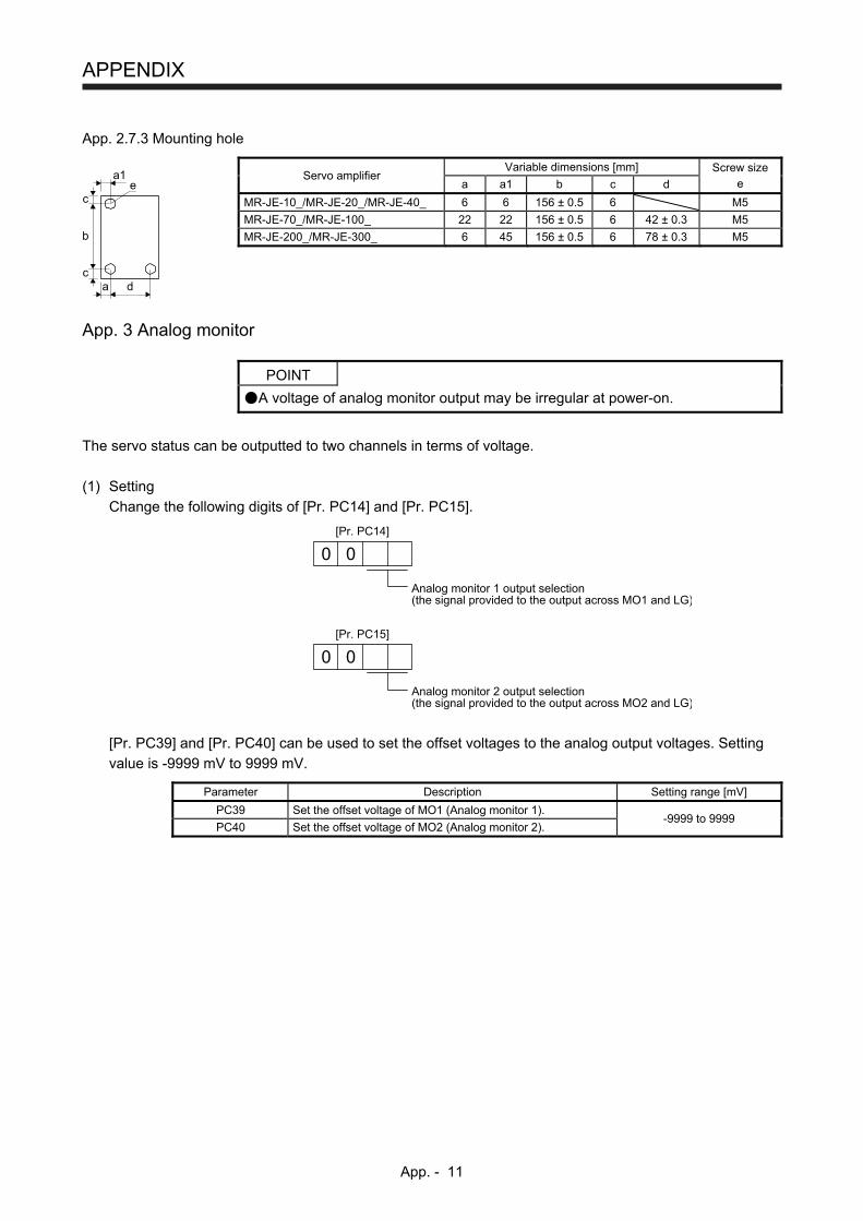
APPENDIX
App. - 11
App. 2.7.3 Mounting hole
dac
b
c
a1e
Servo amplifier Variable dimensions [mm] Screw size
e a a1 b c d
MR-JE-10_/MR-JE-20_/MR-JE-40_ 6 6 156 ± 0.5 6 M5
MR-JE-70_/MR-JE-100_ 22 22 156 ± 0.5 6 42 ± 0.3 M5
MR-JE-200_/MR-JE-300_ 6 45 156 ± 0.5 6 78 ± 0.3 M5
App. 3 Analog monitor
POINT
A voltage of analog monitor output may be irregular at power-on.
The servo status can be outputted to two channels in terms of voltage.
(1) Setting
Change the following digits of [Pr. PC14] and [Pr. PC15].
Analog monitor 1 output selection(the signal provided to the output across MO1 and LG)
0 0
[Pr. PC14]
Analog monitor 2 output selection(the signal provided to the output across MO2 and LG)
0 0
[Pr. PC15]
[Pr. PC39] and [Pr. PC40] can be used to set the offset voltages to the analog output voltages. Setting
value is -9999 mV to 9999 mV.
Parameter Description Setting range [mV]
PC39 Set the offset voltage of MO1 (Analog monitor 1). -9999 to 9999
PC40 Set the offset voltage of MO2 (Analog monitor 2).
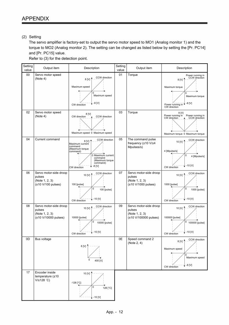
APPENDIX
App. - 12
(2) Setting
The servo amplifier is factory-set to output the servo motor speed to MO1 (Analog monitor 1) and the
torque to MO2 (Analog monitor 2). The setting can be changed as listed below by setting the [Pr. PC14]
and [Pr. PC15] value.
Refer to (3) for the detection point. Setting value
Output item Description Setting value
Output item Description
00 Servo motor speed (Note 4)
Maximum speed
CW direction
CCW direction
Maximum speed
0
8 [V]
-8 [V]
01 Torque
Maximum torque
Power running inCW direction
Power running inCCW direction
Maximum torque
0
8 [V]
-8 [V]
02 Servo motor speed (Note 4)
Maximum speed
CW direction CCW direction
Maximum speed 0
8 [V]
03 Torque
Maximum torque
Power running inCW direction
Power running inCCW direction
Maximum torque 0
8 [V]
04 Current command
Maximum currentcommand(Maximum torquecommand)
CW direction
CCW direction
Maximum currentcommand(Maximum torquecommand)
0
8 [V]
-8 [V]
05 The command pulse frequency (±10 V/±4 Mpulses/s)
4 [Mpulse/s]
CW direction
CCW direction
4 [Mpulse/s]
0
10 [V]
-10 [V]
06 Servo motor-side droop pulses (Note 1, 2, 3) (±10 V/100 pulses)
100 [pulse]
CW direction
CCW direction
100 [pulse]
0
10 [V]
-10 [V]
07 Servo motor-side droop pulses (Note 1, 2, 3) (±10 V/1000 pulses)
1000 [pulse]
CW direction
CCW direction
1000 [pulse]
0
10 [V]
-10 [V]
08 Servo motor-side droop pulses (Note 1, 2, 3) (±10 V/10000 pulses)
10000 [pulse]
CW direction
CCW direction
10000 [pulse]
0
10 [V]
-10 [V]
09 Servo motor-side droop pulses (Note 1, 2, 3) (±10 V/100000 pulses)
100000 [pulse]
CW direction
CCW direction
100000 [pulse]
0
10 [V]
-10 [V]
0D Bus voltage
400 [V]0
8 [V]
0E Speed command 2 (Note 2, 4)
Maximum speed
CW direction
CCW direction
Maximum speed
0
8 [V]
-8 [V]
17 Encoder inside temperature (±10 V/±128 ˚C)
128 [°C]
-128 [°C]
0
10 [V]
-10 [V]
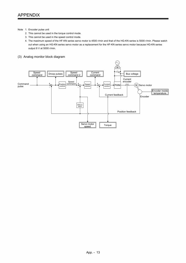
APPENDIX
App. - 13
Note 1. Encoder pulse unit
2. This cannot be used in the torque control mode.
3. This cannot be used in the speed control mode.
4. The maximum speed of the HF-KN series servo motor is 4500 r/min and that of the HG-KN series is 5000 r/min. Please watch
out when using an HG-KN series servo motor as a replacement for the HF-KN series servo motor because HG-KN series
output 8 V at 5000 r/min.
(3) Analog monitor block diagram
Droop pulsesSpeedcommand
Positioncontrol
Speedcontrol PWMCurrent
control
Currentcommand Bus voltage
Speedcommand
Currentencoder
+Servo motor
EncoderCurrent feedback
Position feedback
MCommandpulse
Differen-tiation
Encoder insidetemperature
Servo motorspeed Torque
+
+
--
+
-
Speedcommand 2
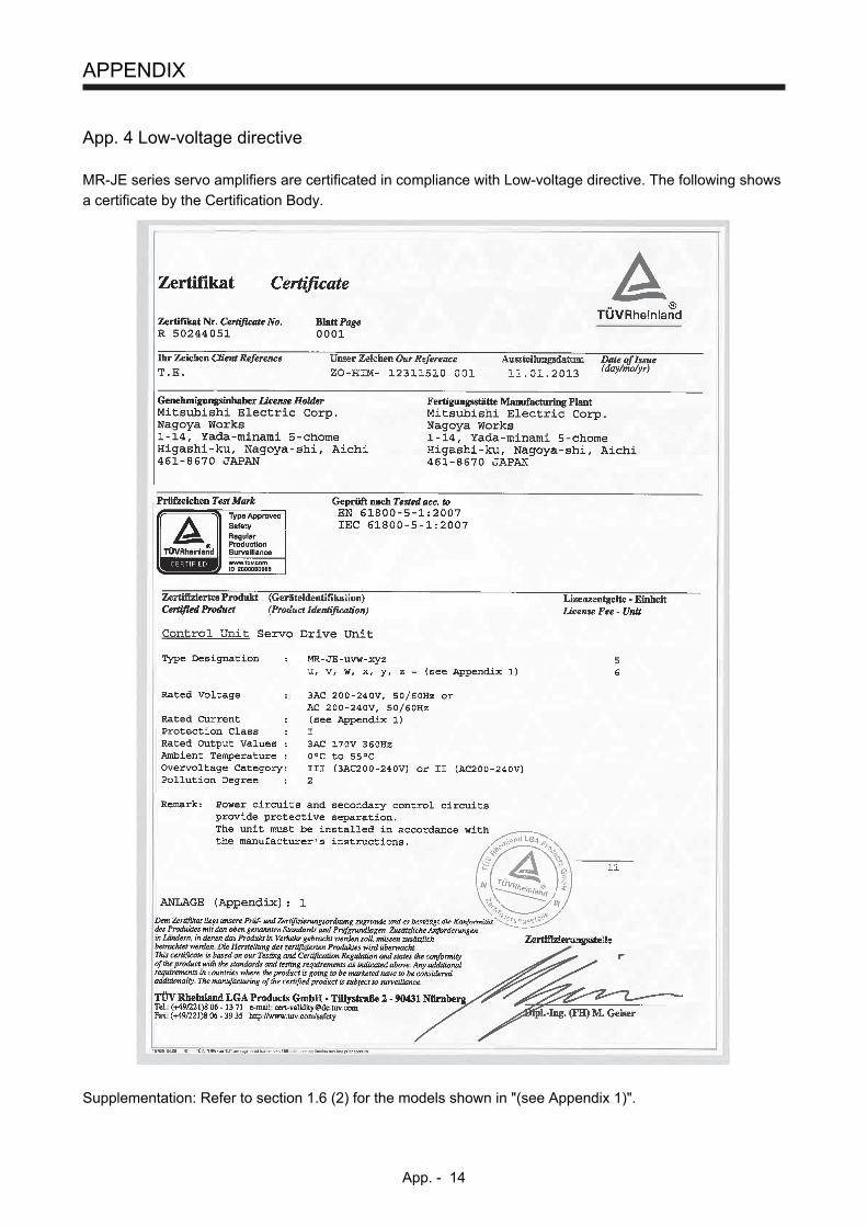
APPENDIX
App. - 14
App. 4 Low-voltage directive
MR-JE series servo amplifiers are certificated in compliance with Low-voltage directive. The following shows
a certificate by the Certification Body.
Supplementation: Refer to section 1.6 (2) for the models shown in "(see Appendix 1)".
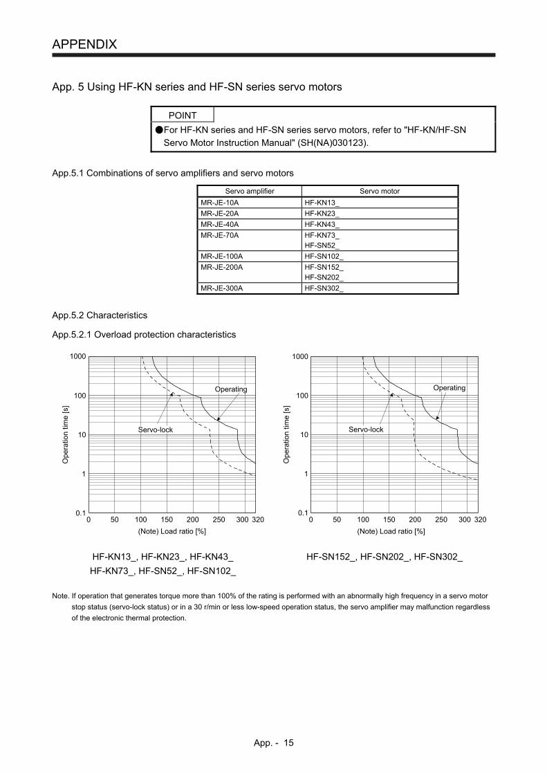
APPENDIX
App. - 15
App. 5 Using HF-KN series and HF-SN series servo motors
POINT
For HF-KN series and HF-SN series servo motors, refer to "HF-KN/HF-SN
Servo Motor Instruction Manual" (SH(NA)030123).
App.5.1 Combinations of servo amplifiers and servo motors
Servo amplifier Servo motor
MR-JE-10A HF-KN13_
MR-JE-20A HF-KN23_
MR-JE-40A HF-KN43_
MR-JE-70A HF-KN73_ HF-SN52_
MR-JE-100A HF-SN102_
MR-JE-200A HF-SN152_ HF-SN202_
MR-JE-300A HF-SN302_
App.5.2 Characteristics
App.5.2.1 Overload protection characteristics
Ope
ratio
n tim
e [s
]
1000
100
10
1
0.1100 200 3000
Servo-lock
Operating
50 150 250
(Note) Load ratio [%]
320
1000
100
10
1
0.1100 200 3000 50 150 250 320
Ope
ratio
n tim
e [s
]
Servo-lock
Operating
(Note) Load ratio [%]
HF-KN13_, HF-KN23_, HF-KN43_
HF-KN73_, HF-SN52_, HF-SN102_
HF-SN152_, HF-SN202_, HF-SN302_
Note. If operation that generates torque more than 100% of the rating is performed with an abnormally high frequency in a servo motor
stop status (servo-lock status) or in a 30 r/min or less low-speed operation status, the servo amplifier may malfunction regardless
of the electronic thermal protection.
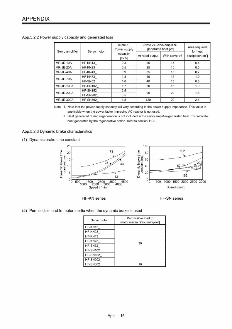
APPENDIX
App. - 16
App.5.2.2 Power supply capacity and generated loss
Servo amplifier Servo motor
(Note 1) Power supply
capacity [kVA]
(Note 2) Servo amplifier-generated heat [W]
Area required for heat
dissipation [m2] At rated output With servo-off
MR-JE-10A HF-KN13_ 0.3 25 15 0.5
MR-JE-20A HF-KN23_ 0.5 25 15 0.5
MR-JE-40A HF-KN43_ 0.9 35 15 0.7
MR-JE-70A HF-KN73_ 1.3 50 15 1.0
HF-SN52_ 1.0 40 15 0.8
MR-JE-100A HF-SN102_ 1.7 50 15 1.0
MR-JE-200A HF-SN152_ 2.5
90 20 1.8 HF-SN202_ 3.5
MR-JE-300A HF-SN302_ 4.8 120 20 2.4
Note 1. Note that the power supply capacity will vary according to the power supply impedance. This value is
applicable when the power factor improving AC reactor is not used.
2. Heat generated during regeneration is not included in the servo amplifier-generated heat. To calculate
heat generated by the regenerative option, refer to section 11.2.
App.5.2.3 Dynamic brake characteristics
(1) Dynamic brake time constant
0
5
10
15
20
25
0 5001000
15002000
25003000
3500 45004000
73
4323
13Dyn
amic
bra
ke ti
me
cons
tant
[ms]
Speed [r/min]
0
20
40
60
80
100
0 500 1000 1500 2000 2500 3000
102
52202
302
152Dyn
amic
bra
ke ti
me
cons
tant
[ms]
Speed [r/min]
HF-KN series HF-SN series
(2) Permissible load to motor inertia when the dynamic brake is used
Servo motor Permissible load to
motor inertia ratio [multiplier]
HF-KN13_
HF-KN23_
HF-KN43_
HF-KN73_ 30
HF-SN52_
HF-SN102_
HF-SN152_
HF-SN202_
HF-SN302_ 16
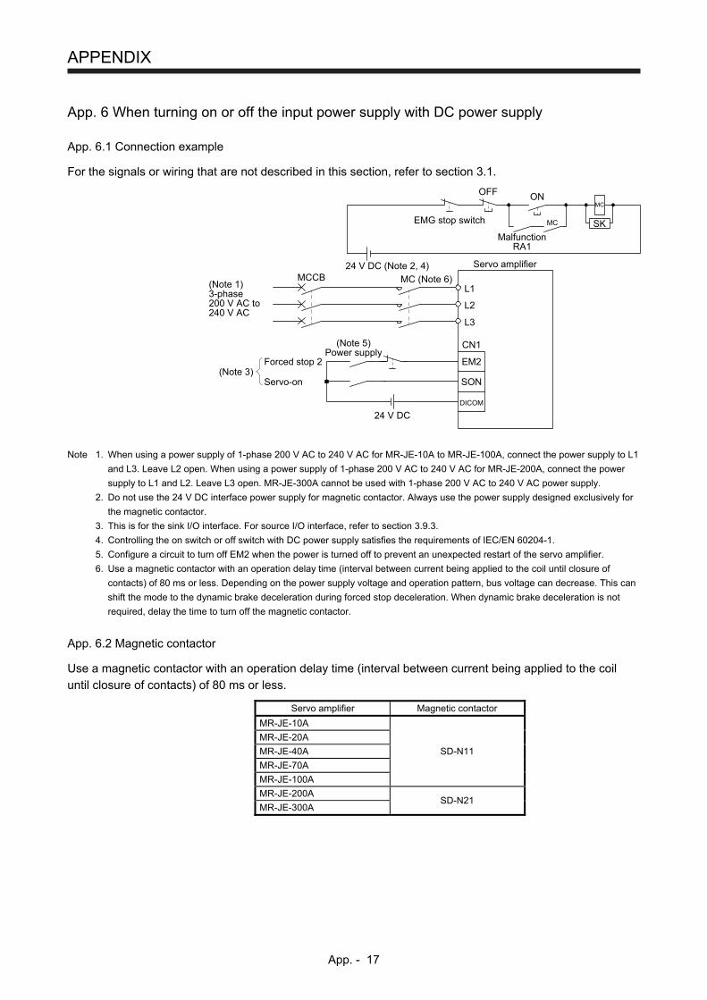
APPENDIX
App. - 17
App. 6 When turning on or off the input power supply with DC power supply
App. 6.1 Connection example
For the signals or wiring that are not described in this section, refer to section 3.1.
MC (Note 6)
24 V DC (Note 2, 4)
24 V DC
(Note 1)3-phase200 V AC to240 V AC
Servo amplifier
CN1
Forced stop 2
Servo-on(Note 3)
EM2
DICOM
SON
(Note 5)Power supply
MCCBL1
L2
L3
MalfunctionRA1
OFF
MC
ONMC
SKEMG stop switch
Note 1. When using a power supply of 1-phase 200 V AC to 240 V AC for MR-JE-10A to MR-JE-100A, connect the power supply to L1
and L3. Leave L2 open. When using a power supply of 1-phase 200 V AC to 240 V AC for MR-JE-200A, connect the power
supply to L1 and L2. Leave L3 open. MR-JE-300A cannot be used with 1-phase 200 V AC to 240 V AC power supply.
2. Do not use the 24 V DC interface power supply for magnetic contactor. Always use the power supply designed exclusively for
the magnetic contactor.
3. This is for the sink I/O interface. For source I/O interface, refer to section 3.9.3.
4. Controlling the on switch or off switch with DC power supply satisfies the requirements of IEC/EN 60204-1.
5. Configure a circuit to turn off EM2 when the power is turned off to prevent an unexpected restart of the servo amplifier.
6. Use a magnetic contactor with an operation delay time (interval between current being applied to the coil until closure of
contacts) of 80 ms or less. Depending on the power supply voltage and operation pattern, bus voltage can decrease. This can
shift the mode to the dynamic brake deceleration during forced stop deceleration. When dynamic brake deceleration is not
required, delay the time to turn off the magnetic contactor.
App. 6.2 Magnetic contactor
Use a magnetic contactor with an operation delay time (interval between current being applied to the coil
until closure of contacts) of 80 ms or less.
Servo amplifier Magnetic contactor
MR-JE-10A
MR-JE-20A
MR-JE-40A SD-N11
MR-JE-70A
MR-JE-100A
MR-JE-200A SD-N21
MR-JE-300A
REVISIONS
*The manual number is given on the bottom left of the back cover. Print Data *Manual Number Revision
May. 2013 SH(NA)030128-A First edition
Jul. 2013 SH(NA)030128-B 4. Additional instructions
(3) Transportation and
installation
Section 1.3
Section 1.6
Chapter 2
Chapter 3
Section 3.2.1
Section 3.4
Section 3.5
Section 3.6.1
Section 3.9.1
Section 3.9.2
Section 3.9.3
Section 5.2.1
Section 11.3
Section 11.6
App. 2
Partially changed.
Partially changed.
Partially changed.
CAUTION is partially changed.
CAUTION is partially changed.
Partially changed.
Partially changed.
Partially changed.
Partially changed.
Partially changed.
Partially changed.
Partially deleted.
Partially added and partially changed in Pr. PA13.
Partially changed.
Partially changed.
Partially changed.
Jan. 2014 SH(NA)030128-C RS-422 function is added.
Section 1.2
Section 1.3
Section 1.5
Section 1.7.1
Section 3.2.1
Section 3.2.2
Section 3.2.3
Section 3.3.2
Section 3.4
Section 3.5
Section 3.9.1
Section 3.10.1
Section 3.10.2
Section 5.1.3
Section 5.2.1
Section 6.2
Section 7.1.1
Section 7.1.3
Section 7.1.4
Section 7.2.3
Section 7.3
Chapter 8
Section 8.1
Section 8.2
Section 8.3
Section 11.3
Section 11.4.1
Section 11.4.2
Section 11.4.3
Section 11.6
Section 11.9
Section 11.11
The diagram is partially changed.
Partially changed.
Added.
Partially changed.
Note is added.
Note is added.
Note is added.
Partially changed.
The table is partially changed.
RS-422 communication is added.
The diagram is partially changed.
Partially changed.
Partially changed.
PC20 and PC21 are added.
Partially changed.
POINT is added.
Partially changed.
Partially changed.
The sentence is added.
Partially changed.
The sentence is added.
POINT is added.
Partially changed.
POINT is added. Partially changed.
POINT is added.
The diagram is partially changed.
Partially changed.
Partially changed.
Added.
The table is changed.
Partially changed.
Partially changed.
Print Data *Manual Number Revision
Jan. 2014 SH(NA)030128-C Chapter 12
App. 2.1.3
App. 2.1.4
App. 2.7.1
Added.
Partially changed.
Partially changed.
Partially changed.
Oct. 2014 SH(NA)030128-D Compatible with HG-KN series/HG-SN series servo motors
Safety Instructions
2.To prevent fire, note the
following
4. Additional instructions
(6) Maintenance, inspection
and parts replacement
«About the manual»
Section 1.3
Section 1.4
Section 1.6
Section 3.1
Section 3.2.1 (1)
Section 3.2.1 (2)
Section 3.2.2
Section 3.2.3
Section 3.3.3
Section 3.10.1
Section 3.10.2
Section 4.5.4
Section 4.5.5
Section 5.2.3
Section 7.1.1
Section 7.1.3
Section 7.1.5
Section 7.2.3
Section 7.2.4
Section 7.3.1
Chapter 8
Section 8.2
Section 8.3
Section 10.3
Section 10.3.1
Section 10.3.2
Section 10.5
Section 11.1.1
Section 11.4.2
Section 11.5
Section 11.6
Section 11.10
Section 12.1.1
App. 1
App. 2
App. 3
App. 5
Partially changed.
Partially changed.
Partially added.
Partially changed.
Note 5 is added.
Servo motor series are changed to HG-KN/HG-SN.
Partially changed.
Partially changed.
Partially changed.
Partially changed.
Partially changed.
Partially changed.
Partially added.
CAUTION is partially added.
POINT is partially changed.
Partially changed.
Partially changed.
Partially changed.
[Pr. PC14] is partially changed.
Partially changed.
POINT is added.
Partially added and partially changed.
Partially changed.
Partially changed.
Partially changed.
POINT is partially added.
Partially changed.
POINT is partially changed.
POINT is partially added.
Partially changed.
Partially changed.
POINT is added.
Partially changed.
Partially changed.
Partially changed.
CAUTION is newly added.
Partially changed.
Partially changed.
Partially changed.
Partially changed.
Partially added.
Newly added.
Apr. 2015 SH(NA)030128-E 1-phase 200 V AC (to 2 kW) is added.
Source pulse input is added.
RS-422 is changed to RS-422/RS-485.
1. To prevent electric shock,
note the following.
An item is deleted.
Print Data *Manual Number Revision
Apr. 2015 SH(NA)030128-E 2. To prevent fire, note the
following.
4. Additional instructions
4. Additional instructions (6)
General instruction
Relevant manuals
Section 1.3
Section 1.4
Section 1.5
Section 1.6 (1)
Section 2.1 (2)
Section 3.1
Section 3.1 (1)
Section 3.1 (2)
Section 3.1 (3)
Section 3.1 (4)
Section 3.2.2 (1)
Section 3.2.2 (2)
Section 3.2.3 (1)
Section 3.2.3 (2)
Section 3.3.1
Section 3.3.3 (2) (a)
Section 3.4
Section 3.5 (2)
Section 3.5 (4)
Section 3.6.1 (1) (b) 1)
Section 3.9.1
Section 3.9.2
Section 3.9.3 (1)
Section 3.9.3 (3)
Section 3.10.1
Section 4.5.4
Section 4.5.7 (2)
Section 4.5.7 (2) (a)
Section 5.1
Section 5.1.3
Section 5.1.4
Section 5.1.6
Section 5.2.1
Section 5.2.2
Section 5.2.3
Section 5.2.4
Section 5.2.6
Section 7.2.3 (1) (a)
Section 7.2.4 (3)
Section 7.3.2
Section 7.4
Chapter 8
Section 10.1
Section 11.2.4 (1)
Section 11.4.2 (1)
Section 11.5
Section 11.6
The content is changed.
The sentences are changed.
An item is added.
The content is added.
The content of the table is changed and added. Note is added.
The content of the table is changed.
The content of the table is changed and added.
The diagram is changed.
The content of POINT is changed.
CAUTION is added. The content of POINT is changed.
The diagram is changed.
The content of POINT is changed.
The title is changed.
Newly added.
The diagram is changed. Note is deleted.
The diagram is changed.
The diagram is changed. Note is deleted.
The diagram is changed.
The content of the table is changed.
The sentences are changed.
The content of the table is changed. Note is added. POINT is added.
The content of the table is changed.
The title is changed.
The diagram is changed.
The diagram is changed. The diagram of Note 2 is changed.
The diagram is added.
The diagram is added.
Newly added.
The sentences of CAUTION are changed.
The table is changed.
The diagram is changed. Note is added.
The content of the table is changed.
Sentences of POINT is changed. Note is added.
[Pr. PC73] is added.
[Pr. PD43] to [Pr. PD46] are added.
The name of [Pr. PF25] is changed.
The sentences of [Pr. PA20] and [Pr. PA26] are changed.
The contents of [Pr. PB25] and [Pr. PB26] are changed.
[Pr. PC27] and [Pr. PC73] are added. Sentences of [Pr. PC43] is
changed. The content of [Pr. PC60] is added.
[Pr. PD43] to [Pr. PC46] are added.
[Pr. PF09] is added. The content of [Pr. PF25] is changed.
The diagram is changed.
Newly added.
Sentences are changed. Sentences of POINT are changed.
Newly added.
The content is changed.
The sentences are changed.
The diagram is changed. Note is added.
The content is changed.
The content of table 11.1 is changed.
CAUTION is added. Table is changed. Note is added. The
sentences are deleted.

Print Data *Manual Number Revision
Apr. 2015 SH(NA)030128-E Section 11.7 (1)
Section 11.7 (2)
Section 11.11 (2)
App. 2
App. 5
App. 6
The diagram is changed.
The table is changed.
The diagram is changed.
The content is changed.
POINT is added.
Newly added.
This manual confers no industrial property rights or any rights of any other kind, nor does it confer any patent licenses. Mitsubishi Electric Corporation cannot be held responsible for any problems involving industrial property rights which may occur as a result of using the contents noted in this manual.
2013 MITSUBISHI ELECTRIC CORPORATION

MEMO

MELSERVO is a trademark or registered trademark of Mitsubishi Electric Corporation in Japan and/or other countries. Microsoft, Windows, Internet Explorer, and Windows Vista are registered trademarks or trademarks of Microsoft Corporation in the United States, Japan, and/or other countries. Intel, Pentium, and Celeron are trademarks of Intel Corporation in the United States and/or other countries. All other product names and company names are trademarks or registered trademarks of their respective companies.
Country/Region Sales office Tel/Fax USA MITSUBISHI ELECTRIC AUTOMATION, INC.
500 Corporate Woods Parkway, Vernon Hills, IL 60061, U.S.A.
Tel Fax
: +1-847-478-2100: +1-847-478-2253
Mexico MITSUBISHI ELECTRIC AUTOMATION, INC. Mexico BranchMariano Escobedo #69, Col. Zona Industrial, Tlalnepantla Edo, C.P.54030, Mexico
Tel Fax
: +52-55-3067-7500: –
Brazil MITSUBISHI ELECTRIC DO BRASIL COMÉRCIO E SERVIÇOS LTDA. Rua Jussara, 1750- Bloco B Anexo, Jardim Santa Cecilia, CEP 06465-070, Barueri - SP, Brasil
Tel Fax
: +55-11-4689-3000: +55-11-4689-3016
Germany MITSUBISHI ELECTRIC EUROPE B.V. German BranchGothaer Strasse 8, D-40880 Ratingen, Germany
Tel Fax
: +49-2102-486-0: +49-2102-486-1120
UK MITSUBISHI ELECTRIC EUROPE B.V. UK BranchTravellers Lane, Hatfield, Hertfordshire, AL10 8XB, U.K.
Tel Fax
: +44-1707-28-8780: +44-1707-27-8695
Italy MITSUBISHI ELECTRIC EUROPE B.V. Italian BranchCentro Direzionale Colleoni - Palazzo Sirio Viale Colleoni 7, 20864 Agrate Brianza (Milano) Italy
Tel Fax
: +39-039-60531: +39-039-6053-312
Spain MITSUBISHI ELECTRIC EUROPE, B.V. Spanish BranchCarretera de Rubí, 76-80-Apdo. 420, 08173 Sant Cugat del Vallés (Barcelona), Spain
Tel Fax
: +34-935-65-3131: +34-935-89-1579
France MITSUBISHI ELECTRIC EUROPE B.V. French Branch25, Boulevard des Bouvets, F-92741 Nanterre Cedex, France
Tel Fax
: +33-1-55-68-55-68: +33-1-55-68-57-57
Czech Republic MITSUBISHI ELECTRIC EUROPE B.V. Czech BranchAvenir Business Park, Radlicka 751/113e, 158 00 Praha5, Czech Republic
Tel Fax
: +420-251-551-470: +420-251-551-471
Poland MITSUBISHI ELECTRIC EUROPE B.V. Polish Branchul. Krakowska 50, 32-083 Balice, Poland
Tel Fax
: +48-12-630-47-00: +48-12-630-47-01
Russia MITSUBISHI ELECTRIC EUROPE B.V. Russian Branch St. Petersburg officePiskarevsky pr. 2, bld 2, lit “Sch”, BC “Benua”, office 720; RU-195027 St. Petersburg, Russia
Tel Fax
: +7-812-633-3497: +7-812-633-3499
Sweden MITSUBISHI ELECTRIC EUROPE B.V. (Scandinavia) Fjelievägen 8, SE-22736 Lund, Sweden
Tel Fax
: +46-8-625-10-00: +46-46-39-70-18
Turkey MITSUBISHI ELECTRIC TURKEY A.Ş Ümraniye BranchŞerifali Mahallesi Nutuk Sokak No:5, TR-34775 Ümraniye, İstanbul, Türkey
Tel Fax
: +90-216-526-3990: +90-216-526-3995
UAE MITSUBISHI ELECTRIC EUROPE B.V. Dubai Branch Dubai Silicon Oasis, P.O.BOX 341241, Dubai, U.A.E.
Tel Fax
: +971-4-3724716: +971-4-3724721
South Africa ADROIT TECHNOLOGIES 20 Waterford Office Park, 189 Witkoppen Road, Fourways, Johannesburg, South Africa
Tel Fax
: +27-11-658-8100: +27-11-658-8101
China MITSUBISHI ELECTRIC AUTOMATION (CHINA) LTD.No.1386 Hongqiao Road, Mitsubishi Electric Automation Center, Shanghai, China
Tel Fax
: +86-21-2322-3030: +86-21-2322-3000
Taiwan SETSUYO ENTERPRISE CO., LTD.6F, No.105, Wugong 3rd Road, Wugu District, New Taipei City 24889, Taiwan, R.O.C.
Tel Fax
: +886-2-2299-2499: +886-2-2299-2509
Korea MITSUBISHI ELECTRIC AUTOMATION KOREA CO., LTD. 7F-9F, Gangseo Hangang Xi-tower A, 401, Yangcheon-ro, Gangseo-Gu, Seoul 157-801, Korea
Tel Fax
: +82-2-3660-9510: +82-2-3664-8372/8335
Singapore MITSUBISHI ELECTRIC ASIA PTE. LTD.307, Alexandra Road, Mitsubishi Electric Building, Singapore 159943
Tel Fax
: +65-6473-2308: +65-6476-7439
Thailand MITSUBISHI ELECTRIC FACTORY AUTOMATION (THAILAND) CO., LTD.12th Floor, SV.City Building, Office Tower 1, No. 896/19 and 20 Rama 3 Road, Kwaeng Bangpongpang, Khet Yannawa, Bangkok 10120, Thailand
Tel Fax
: +66-2682-6522 to 6531: +66-2682-6020
Indonesia PT. MITSUBISHI ELECTRIC INDONESIAGedung Jaya 11th Floor, JL. MH. Thamrin No.12, Jakarta Pusat 10340, Indonesia
Tel Fax
: +62-21-3192-6461: +62-21-3192-3942
Vietnam MITSUBISHI ELECTRIC VIETNAM COMPANY LIMITED Unit 01-04, 10th Floor, Vincom Center, 72 Le Thanh Ton Street, District 1, Ho Chi Minh City, Vietnam
Tel Fax
: +84-8-3910-5945: +84-8-3910-5947
India MITSUBISHI ELECTRIC INDIA PVT. LTD. Pune BranchEmerald House, EL -3, J Block, M.I.D.C Bhosari, Pune - 411026, Maharashtra, India
Tel Fax
: +91-20-2710-2000: +91-20-2710-2100
Australia MITSUBISHI ELECTRIC AUSTRALIA PTY. LTD.348 Victoria Road, P.O. Box 11, Rydalmere, N.S.W 2116, Australia
Tel Fax
: +61-2-9684-7777: +61-2-9684-7245
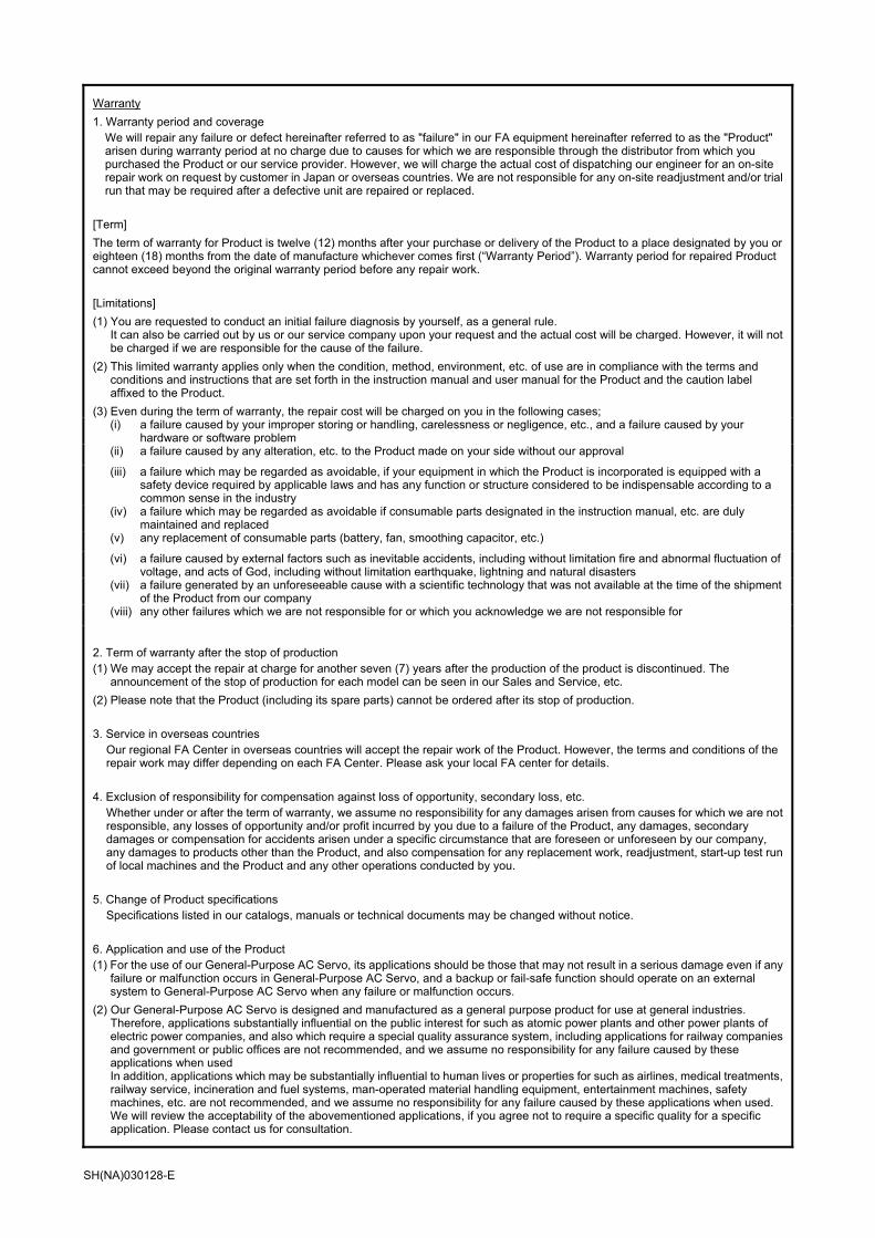
Warranty
1. Warranty period and coverage We will repair any failure or defect hereinafter referred to as "failure" in our FA equipment hereinafter referred to as the "Product" arisen during warranty period at no charge due to causes for which we are responsible through the distributor from which you purchased the Product or our service provider. However, we will charge the actual cost of dispatching our engineer for an on-site repair work on request by customer in Japan or overseas countries. We are not responsible for any on-site readjustment and/or trial run that may be required after a defective unit are repaired or replaced.
[Term]
The term of warranty for Product is twelve (12) months after your purchase or delivery of the Product to a place designated by you or eighteen (18) months from the date of manufacture whichever comes first (“Warranty Period”). Warranty period for repaired Product cannot exceed beyond the original warranty period before any repair work.
[Limitations]
(1) You are requested to conduct an initial failure diagnosis by yourself, as a general rule. It can also be carried out by us or our service company upon your request and the actual cost will be charged. However, it will not be charged if we are responsible for the cause of the failure.
(2) This limited warranty applies only when the condition, method, environment, etc. of use are in compliance with the terms and
conditions and instructions that are set forth in the instruction manual and user manual for the Product and the caution label affixed to the Product.
(3) Even during the term of warranty, the repair cost will be charged on you in the following cases;
(i) a failure caused by your improper storing or handling, carelessness or negligence, etc., and a failure caused by your
hardware or software problem
(ii) a failure caused by any alteration, etc. to the Product made on your side without our approval
(iii) a failure which may be regarded as avoidable, if your equipment in which the Product is incorporated is equipped with a
safety device required by applicable laws and has any function or structure considered to be indispensable according to a common sense in the industry
(iv) a failure which may be regarded as avoidable if consumable parts designated in the instruction manual, etc. are duly
maintained and replaced
(v) any replacement of consumable parts (battery, fan, smoothing capacitor, etc.)
(vi) a failure caused by external factors such as inevitable accidents, including without limitation fire and abnormal fluctuation of
voltage, and acts of God, including without limitation earthquake, lightning and natural disasters
(vii) a failure generated by an unforeseeable cause with a scientific technology that was not available at the time of the shipment
of the Product from our company
(viii) any other failures which we are not responsible for or which you acknowledge we are not responsible for
2. Term of warranty after the stop of production (1) We may accept the repair at charge for another seven (7) years after the production of the product is discontinued. The
announcement of the stop of production for each model can be seen in our Sales and Service, etc.
(2) Please note that the Product (including its spare parts) cannot be ordered after its stop of production.
3. Service in overseas countries
Our regional FA Center in overseas countries will accept the repair work of the Product. However, the terms and conditions of the repair work may differ depending on each FA Center. Please ask your local FA center for details.
4. Exclusion of responsibility for compensation against loss of opportunity, secondary loss, etc.
Whether under or after the term of warranty, we assume no responsibility for any damages arisen from causes for which we are not responsible, any losses of opportunity and/or profit incurred by you due to a failure of the Product, any damages, secondary damages or compensation for accidents arisen under a specific circumstance that are foreseen or unforeseen by our company, any damages to products other than the Product, and also compensation for any replacement work, readjustment, start-up test run of local machines and the Product and any other operations conducted by you.
5. Change of Product specifications
Specifications listed in our catalogs, manuals or technical documents may be changed without notice.
6. Application and use of the Product (1) For the use of our General-Purpose AC Servo, its applications should be those that may not result in a serious damage even if any
failure or malfunction occurs in General-Purpose AC Servo, and a backup or fail-safe function should operate on an external system to General-Purpose AC Servo when any failure or malfunction occurs.
(2) Our General-Purpose AC Servo is designed and manufactured as a general purpose product for use at general industries.
Therefore, applications substantially influential on the public interest for such as atomic power plants and other power plants of electric power companies, and also which require a special quality assurance system, including applications for railway companies and government or public offices are not recommended, and we assume no responsibility for any failure caused by these applications when used In addition, applications which may be substantially influential to human lives or properties for such as airlines, medical treatments, railway service, incineration and fuel systems, man-operated material handling equipment, entertainment machines, safety machines, etc. are not recommended, and we assume no responsibility for any failure caused by these applications when used. We will review the acceptability of the abovementioned applications, if you agree not to require a specific quality for a specific application. Please contact us for consultation.
SH(NA)030128-E

SH (NA) 030128-E (1504) MEE Printed in Japan Specifications are subject to change without notice. This Instruction Manual uses recycled paper.
MODEL
MODELCODE
General-Purpose AC Servo
MR
-JE-_A
SE
RV
O A
MP
LIF
IER
INS
TR
UC
TIO
N M
AN
UA
L
HEAD OFFICE : TOKYO BLDG MARUNOUCHI TOKYO 100-8310
MODEL
MR-JE-_ASERVO AMPLIFIER INSTRUCTION MANUAL
General-Purpose Interface AC Servo
1CW706
MR-JE-A SERVOAMPLIFIER INSTRUCTIONMANUAL
E
E


![James m._kouzes,_barry_z._posner,_elaine_biech]_a](https://img.pdfslide.us/doc/110x75/541320e57bef0a40598b4f3f/james-mkouzesbarryzposnerelainebiecha.jpg)