Embed Size (px)
Citation preview

Departamento de Engenharia Electrotécnica e de Computadores
Model Morphisms (MoMo) to Enable Language
Independent Information Models and Interoperable
Business Networks
By
Filipe André Sobral Correia
MSc. Dissertation presented at Faculdade de Ciências e Tecnologia of
Universidade Nova de Lisboa to obtain the Master degree in Electrical and
Computer Engineering, held under the guidance of
Doctor Ricardo Luís Rosa Jardim-Gonçalves
Lisboa
September 2010

ii

iii
ACKNOWLEDGEMENTS
I would like to thank all those who in some way contributed and supported me during
the realisation of my course and this dissertation.
To my parents, brother and sister in-law who supported me from the beginning and
throughout all these long years and never gave up on believing in me.
To Lua, my moonlight which guided me in these long seven years with many dark
nights. Thank you for always being there and making me believing in myself.
To my advisor Doctor Ricardo Gonçalves for believing in my capabilities and giving me
the honour of his advices, the time devoted to assist me and the assertive guidance towards
the completion of this dissertation.
To all my colleagues at GRIS, especially to Carlos Agostinho, João Sarraipa and
Fernando Ferreira, who took me as family and supported me from very closely.
Finally, a very special thanks to all my friends who shared my worries throughout these
long past years especially to Luís Martins, Tiago Gaspar and Fábio Coelho. I will never forget
those RedBull-powered nights at the University!

iv
v
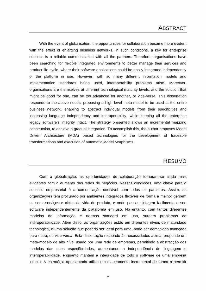
ABSTRACT
With the event of globalisation, the opportunities for collaboration became more evident
with the effect of enlarging business networks. In such conditions, a key for enterprise
success is a reliable communication with all the partners. Therefore, organisations have
been searching for flexible integrated environments to better manage their services and
product life cycle, where their software applications could be easily integrated independently
of the platform in use. However, with so many different information models and
implementation standards being used, interoperability problems arise. Moreover,
organisations are themselves at different technological maturity levels, and the solution that
might be good for one, can be too advanced for another, or vice-versa. This dissertation
responds to the above needs, proposing a high level meta-model to be used at the entire
business network, enabling to abstract individual models from their specificities and
increasing language independency and interoperability, while keeping all the enterprise
legacy software‟s integrity intact. The strategy presented allows an incremental mapping
construction, to achieve a gradual integration. To accomplish this, the author proposes Model
Driven Architecture (MDA) based technologies for the development of traceable
transformations and execution of automatic Model Morphisms.
RESUMO
Com a globalização, as oportunidades de colaboração tornaram-se ainda mais
evidentes com o aumento das redes de negócios. Nessas condições, uma chave para o
sucesso empresarial é a comunicação confiável com todos os parceiros. Assim, as
organizações têm procurado por ambientes integrados flexíveis de forma a melhor gerirem
os seus serviços e ciclos de vida de produto, e onde possam integrar facilmente o seu
software independentemente da plataforma em uso. No entanto, com tantos diferentes
modelos de informação e normas standard em uso, surgem problemas de
interoperabilidade. Além disso, as organizações estão em diferentes níveis de maturidade
tecnológica, e uma solução que poderia ser ideal para uma, pode ser demasiado avançada
para outra, ou vice-versa. Esta dissertação responde às necessidades acima, propondo um
meta-modelo de alto nível usado por uma rede de empresas, permitindo a abstracção dos
modelos das suas especificidades, aumentando a independência de linguagem e
interoperabilidade, enquanto mantém a integridade de todo o software de uma empresa
intacto. A estratégia apresentada utiliza um mapeamento incremental de forma a permitir

vi
uma integração gradual. Para isto, o autor propõe o uso de tecnologias baseadas em MDA
para o desenvolvimento de morfismos rastreáveis de modelos.
vii
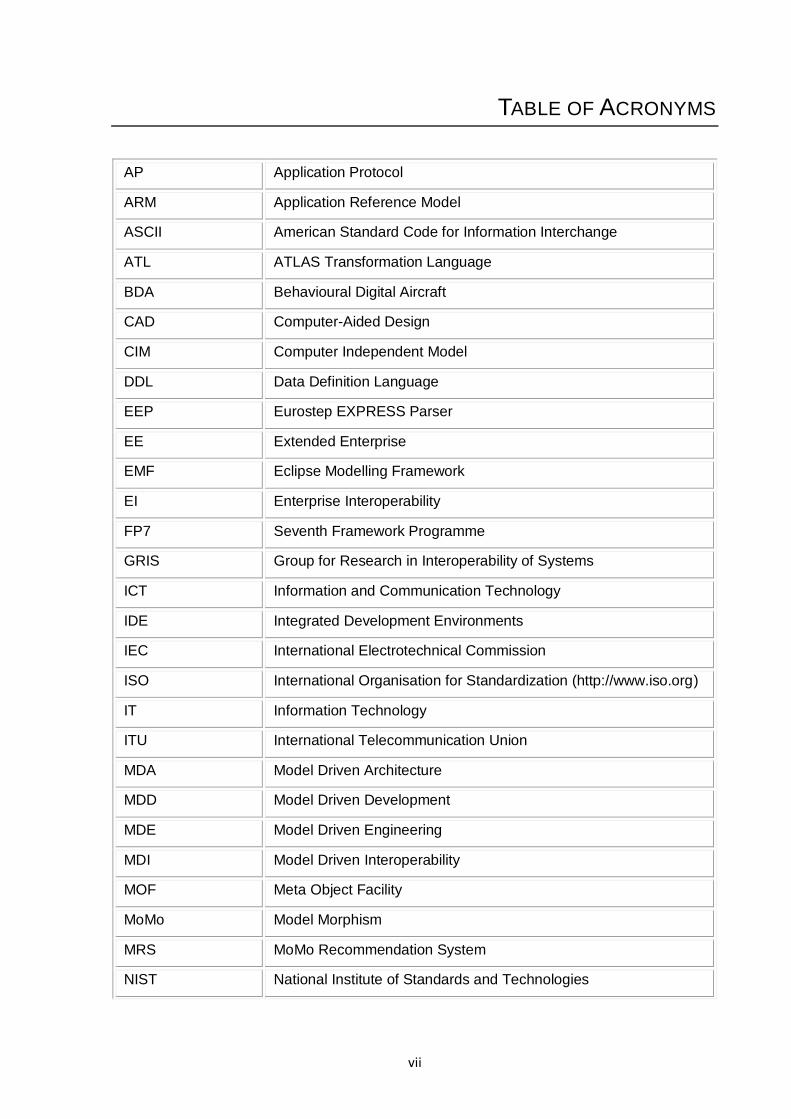
TABLE OF ACRONYMS
AP Application Protocol
ARM Application Reference Model
ASCII American Standard Code for Information Interchange
ATL ATLAS Transformation Language
BDA Behavioural Digital Aircraft
CAD Computer-Aided Design
CIM Computer Independent Model
DDL Data Definition Language
EEP Eurostep EXPRESS Parser
EE Extended Enterprise
EMF Eclipse Modelling Framework
EI Enterprise Interoperability
FP7 Seventh Framework Programme
GRIS Group for Research in Interoperability of Systems
ICT Information and Communication Technology
IDE Integrated Development Environments
IEC International Electrotechnical Commission
ISO International Organisation for Standardization (http://www.iso.org)
IT Information Technology
ITU International Telecommunication Union
MDA Model Driven Architecture
MDD Model Driven Development
MDE Model Driven Engineering
MDI Model Driven Interoperability
MOF Meta Object Facility
MoMo Model Morphism
MRS MoMo Recommendation System
NIST National Institute of Standards and Technologies
viii
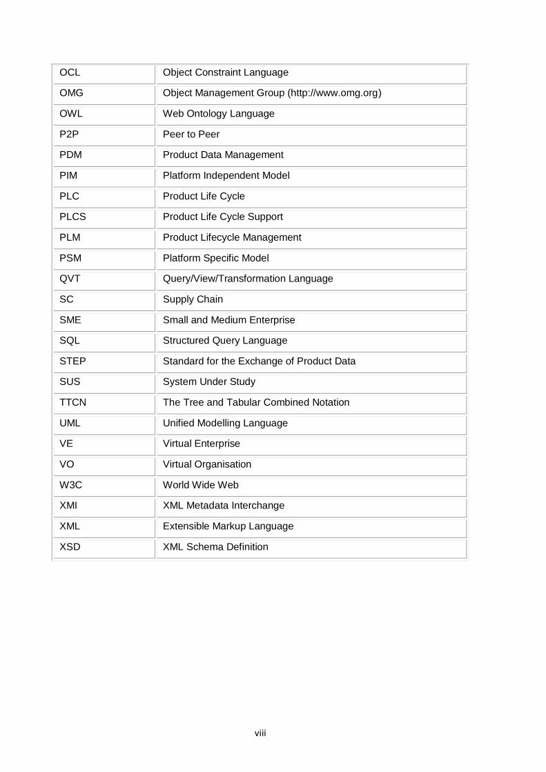
OCL Object Constraint Language
OMG Object Management Group (http://www.omg.org)
OWL Web Ontology Language
P2P Peer to Peer
PDM Product Data Management
PIM Platform Independent Model
PLC Product Life Cycle
PLCS Product Life Cycle Support
PLM Product Lifecycle Management
PSM Platform Specific Model
QVT Query/View/Transformation Language
SC Supply Chain
SME Small and Medium Enterprise
SQL Structured Query Language
STEP Standard for the Exchange of Product Data
SUS System Under Study
TTCN The Tree and Tabular Combined Notation
UML Unified Modelling Language
VE Virtual Enterprise
VO Virtual Organisation
W3C World Wide Web
XMI XML Metadata Interchange
XML Extensible Markup Language
XSD XML Schema Definition
ix
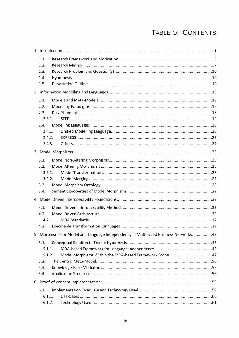
TABLE OF CONTENTS
1. Introduction ................................................................................................................................... 1
1.1. Research Framework and Motivation .................................................................................. 5
1.2. Research Method ................................................................................................................ 7
1.3. Research Problem and Question(s) .................................................................................... 10
1.4. Hypothesis ......................................................................................................................... 10
1.5. Dissertation Outline ........................................................................................................... 10
2. Information Modelling and Languages ......................................................................................... 13
2.1. Models and Meta-Models .................................................................................................. 13
2.2. Modelling Paradigms ......................................................................................................... 16
2.3. Data Standards .................................................................................................................. 18
2.3.1. STEP ........................................................................................................................... 19
2.4. Modelling Languages ......................................................................................................... 20
2.4.1. Unified Modelling Language ....................................................................................... 20
2.4.2. EXPRESS ..................................................................................................................... 22
2.4.3. Others ........................................................................................................................ 24
3. Model Morphisms ........................................................................................................................ 25
3.1. Model Non-Altering Morphisms......................................................................................... 25
3.2. Model Altering Morphisms ................................................................................................ 26
3.2.1. Model Transformation ............................................................................................... 27
3.2.2. Model Merging .......................................................................................................... 27
3.3. Model Morphism Ontology ................................................................................................ 28
3.4. Semantic properties of Model Morphisms ......................................................................... 29
4. Model Driven Interoperability Foundations .................................................................................. 33
4.1. Model Driven Interoperability Method .............................................................................. 33
4.2. Model Driven Architecture ................................................................................................ 35
4.2.1. MDA Standards .......................................................................................................... 37
4.3. Executable Transformation Languages ............................................................................... 39
5. Morphisms for Model and Language Independency in Multi-Sized Business Networks ................. 43
5.1. Conceptual Solution to Enable Hypothesis ......................................................................... 43
5.1.1. MDA-based Framework for Language Independency ................................................. 45
5.1.2. Model Morphisms Within the MDA-based Framework Scope..................................... 47
5.2. The Central Meta-Model.................................................................................................... 50
5.3. Knowledge-Base Mediator ................................................................................................. 55
5.4. Application Scenario .......................................................................................................... 56
6. Proof-of-concept Implementation ................................................................................................ 59
6.1. Implementation Overview and Technology Used ............................................................... 59
6.1.1. Use-Cases .................................................................................................................. 60
6.1.2. Technology Used ........................................................................................................ 61
x
6.2. Implementation Steps ....................................................................................................... 63
6.2.1. Step 0 – Central Meta-Model definition and Model Mappings ................................... 64
6.2.2. Step 1 – Eurostep EXPRESS Parser Model Validation and XML representation ............ 67
6.2.3. Step 2 – EXPRESS Injector .......................................................................................... 68
6.2.4. Step 3 and 5 – Bidirectional EXPRESS transformations to Central Model .................... 70
6.2.5. Step 4 – Central Models to Central Models (UC2) ....................................................... 73
6.2.6. Step 6 – Exporting EXPRESS Models back to text and/or XML ..................................... 73
7. Implementation Testing and Hypothesis Validation ..................................................................... 77
7.1. Testing Methodologies ...................................................................................................... 77
7.1.1. iSurf Functional and Non-Functional Evaluation Methodology ................................... 78
7.1.2. ISO/IEC 9646 (ITU-T X.290) – Framework and Methodology for Conformance Testing of
Implementations of OSI and ITU Protocols ................................................................................ 80
7.1.3. Tree and Tabular Combined Notation (TTCN) – Test Notation Standard ..................... 82
7.1.4. Adopted Test Methodology ....................................................................................... 83
7.2. Requirements and Functionalities Evaluation .................................................................... 84
7.3. Functional Testing ............................................................................................................. 86
7.4. Non-Functional Testing ...................................................................................................... 90
7.5. Scientific Validation ........................................................................................................... 92
8. Conclusions and Future Work ...................................................................................................... 95
8.1. Future Work ...................................................................................................................... 97
9. References ................................................................................................................................... 99
10. Annex ........................................................................................................................................ 105
10.1. Requirements and Functionalities of the System ............................................................. 105
10.1.1. Requirements .......................................................................................................... 105
10.1.2. Functionalities ......................................................................................................... 105
10.2. Modelling languages meta-models to Central Meta-Model mappings.............................. 106
10.2.1. EXPRESS Mappings................................................................................................... 106
10.2.2. XML Schema (XSD) Mappings ................................................................................... 109
xi
TABLE OF FIGURES
Figure 1.1 – Interoperability on all layers of enterprises [17] .............................................................. 3
Figure 1.2 – Classical research methodology [25] ............................................................................... 7
Figure 1.3 – Variation of reliability and newness of publications [26] ................................................. 8
Figure 2.1 – Relationship between models, meta-models, modelling languages and SUS ..................14
Figure 2.2 – OMG’s four level meta-modelling architecture ..............................................................15
Figure 2.3 – Objectivist vs. Subjectivist approaches to data modelling [28]........................................17
Figure 2.4 – Simple example of an UML class diagram model ............................................................21
Figure 2.5 – Simple example of an EXPRESS text format model .........................................................22
Figure 2.6 – Simple example of an EXPRESS-G format model .............................................................24
Figure 3.1 – Model Altering Morphism applied to Model A ...............................................................25
Figure 3.2 – Example of “1-to-1” and “n-to-1” relationships *61+ .......................................................26
Figure 3.3 – Model Transformation ...................................................................................................27
Figure 3.4 – The Model Morphism Ontology [73] ..............................................................................29
Figure 3.5 – Semantic mismatches examples ....................................................................................31
Figure 3.6 – Abstracting and refining operations on models ..............................................................31
Figure 4.1 – Reference Model for MDI [81] .......................................................................................34
Figure 4.2 – Levels of Model Driven Framework ................................................................................37
Figure 4.3 – Instantiation of the OMG's meta-modelling architecture with MDA open standards ......38
Figure 4.4 – QVT languages layered architecture...............................................................................39
Figure 5.1 – High level abstraction framework of the conceptual solution .........................................44
Figure 5.2 – Framework for model and language independency based on MDA ................................46
Figure 5.3 – Detail of the framework for model and language independency based on MDA ............48
Figure 5.4 – Central UML Meta-Model proposal................................................................................51
Figure 5.5 – Central Model representation of a simple model example .............................................54
Figure 5.6 – Structure of Knowledge-Base Mediator .........................................................................55
Figure 5.7 – Furniture Supply Chain example [1] ...............................................................................56
Figure 5.8 – Catalogue example of two different enterprises ............................................................57
Figure 5.9 – Application scenario ......................................................................................................58
Figure 6.1 – EXPRESS to EXPRESS model morphisms use-case (UC1)..................................................60
Figure 6.2 – Data injection and Central Model to Central Model use-case (UC2) ...............................60
Figure 6.3 – Proof-of-concept Implementation Overview (UC1 and UC2) ..........................................62
Figure 6.4 – Mapping Status of EXPRESS EXP2CM and CM2EXP ATL Rules .........................................66
Figure 6.5 – Simple Family EXPRESS text model.................................................................................67
Figure 6.6 – Simple Family EXPRESS XML text model (output of EEP) ................................................68
Figure 6.7 – XML Meta-Model ...........................................................................................................69
Figure 6.8 – Simple Family EXPRESS XML model (XML meta-model instance) ....................................70
Figure 6.9 – Simple Family XMI serialised EXPRESS meta-model instance after injection ...................71
Figure 6.10 – Simple Family model as Central Model representation ................................................72
Figure 6.11 – Simple Family model as EXPRESS meta-model instance (output of “CM2EXP”) .............72
Figure 6.12 – Simple Family model extracted to XML from an EXPRESS meta-model instance ...........74
Figure 6.13 – Simple Family model transformed into text from an EXPRESS meta-model instance ....74
Figure 7.1 – Global overview of the conformance testing process [106] ............................................81

xii
xiii
LIST OF TABLES
Table 3.1 – Semantic Mismatches (based on [61] and [74]) ...............................................................30
Table 6.1 – Purpose of the used technologies and tools by the proof-of-concept implementation ....63
Table 6.2 – EXPRESS’ “EntityType” mapping to the Central Meta-Model (mapping extract)...............64
Table 7.1 – Simplified example of a TTCN table test ..........................................................................83
Table 7.2 – XML (text) to EXPRESS model (instance of EXPRESS meta-model) transformation test case
.........................................................................................................................................................86
Table 7.3 – EXPRESS model to Central Model transformation test case .............................................87
Table 7.4 – Central Model to EXPRESS model transformation test case .............................................87
Table 7.5 – EXPRESS model to EXPRESS text transformation test case ...............................................88
Table 7.6 – EXPRESS model (instance of EXPRESS meta-model) to XML (text) transformation test case
.........................................................................................................................................................88
Table 7.7 – “Product concept identification” ATL transformations time measurements ....................91
Table 7.8 – “AP236 Furniture Catalogue and Interior Design” ATL transformations time
measurements ..................................................................................................................................92

xiv
1
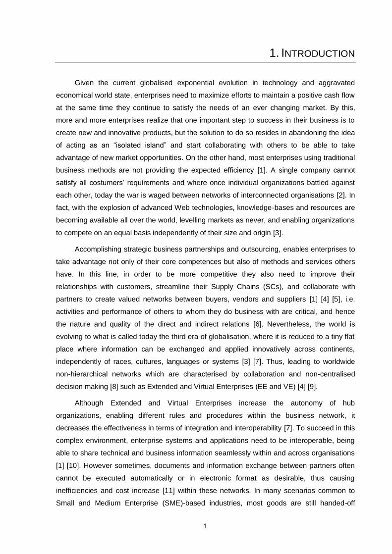
1. INTRODUCTION
Given the current globalised exponential evolution in technology and aggravated
economical world state, enterprises need to maximize efforts to maintain a positive cash flow
at the same time they continue to satisfy the needs of an ever changing market. By this,
more and more enterprises realize that one important step to success in their business is to
create new and innovative products, but the solution to do so resides in abandoning the idea
of acting as an “isolated island” and start collaborating with others to be able to take
advantage of new market opportunities. On the other hand, most enterprises using traditional
business methods are not providing the expected efficiency [1]. A single company cannot
satisfy all costumers‟ requirements and where once individual organizations battled against
each other, today the war is waged between networks of interconnected organisations [2]. In
fact, with the explosion of advanced Web technologies, knowledge-bases and resources are
becoming available all over the world, levelling markets as never, and enabling organizations
to compete on an equal basis independently of their size and origin [3].
Accomplishing strategic business partnerships and outsourcing, enables enterprises to
take advantage not only of their core competences but also of methods and services others
have. In this line, in order to be more competitive they also need to improve their
relationships with customers, streamline their Supply Chains (SCs), and collaborate with
partners to create valued networks between buyers, vendors and suppliers [1] [4] [5], i.e.
activities and performance of others to whom they do business with are critical, and hence
the nature and quality of the direct and indirect relations [6]. Nevertheless, the world is
evolving to what is called today the third era of globalisation, where it is reduced to a tiny flat
place where information can be exchanged and applied innovatively across continents,
independently of races, cultures, languages or systems [3] [7]. Thus, leading to worldwide
non-hierarchical networks which are characterised by collaboration and non-centralised
decision making [8] such as Extended and Virtual Enterprises (EE and VE) [4] [9].
Although Extended and Virtual Enterprises increase the autonomy of hub
organizations, enabling different rules and procedures within the business network, it
decreases the effectiveness in terms of integration and interoperability [7]. To succeed in this
complex environment, enterprise systems and applications need to be interoperable, being
able to share technical and business information seamlessly within and across organisations
[1] [10]. However sometimes, documents and information exchange between partners often
cannot be executed automatically or in electronic format as desirable, thus causing
inefficiencies and cost increase [11] within these networks. In many scenarios common to
Small and Medium Enterprise (SME)-based industries, most goods are still handed-off
2
through faxes, phone calls, paper documents, and a wide range of proprietary systems [8]
[12].
If systems are only partially interoperable, translation or data re-entry is required for
information flows, thus incurring on several types of costs. In SCs if the lower tiers do not
have the financial resources or technical capability to support interoperability, their internal
processes and communications are likely to be significantly less efficient, thus harming the
performance of the entire network. This way, achieving an interoperable state inside
heterogeneous networks is still an ongoing challenge hindered by the fact that they are,
intrinsically, composed by many distributed hardware and software using different models
and semantics [13]. This situation is even worst in the advent of the evolution of the
enterprise systems and applications, which such dynamics results in increasing the
interoperability problem with the continuous need for models adjustments and semantics
harmonization, since:
Retail and manufacturing systems are constantly adapting to new market and
customer requirements, thus answering the need to respond with faster and
better quality production;
New organizations are constantly entering and leaving collaboration networks,
leading to a constant fluctuation and evolution of system models.
All these factors are making interoperability difficult to sustain [7]. Being the latter the
capability which two systems have to understand one and other to function together, it is
directly related with the heterogeneity of model languages, communication capabilities,
databases and semantics. Differences in all these factors hide a great barrier to achieve the
time-to-market symbiosis that can unleash a solution more valuable than the sum of its
creators [1] [4] [5] [14]. Enterprise Interoperability (EI) is more than just a communication
support: it is about sharing functionality and information between systems at different levels
[14], and a software approach to maximize the benefits of diversity, rather than to integrate
the different system into one. EI is a relatively recent term that describes a field of activity
with the aim to improve the manner in which enterprises, by means of Information and
Communications Technologies (ICT), interoperate with other enterprises, organisations, or
with other business units of the same enterprise in order to conduct their business [15]. On
the other hand, those different levels of communication can be framed in a five layers of
interoperability as defined by the holistic approach to interoperability by the “Advanced
Technologies for Interoperability of Heterogeneous Enterprise Networks and their
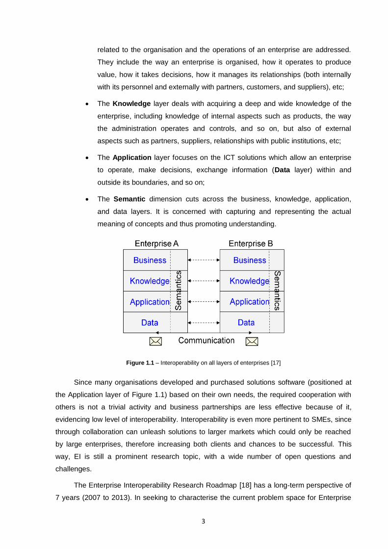
Application” (ATHENA [16]) European project (depicted in Figure 1.1) [17]:
The Business layer is located at the top of the framework, where all issues
3
related to the organisation and the operations of an enterprise are addressed.
They include the way an enterprise is organised, how it operates to produce
value, how it takes decisions, how it manages its relationships (both internally
with its personnel and externally with partners, customers, and suppliers), etc;
The Knowledge layer deals with acquiring a deep and wide knowledge of the
enterprise, including knowledge of internal aspects such as products, the way
the administration operates and controls, and so on, but also of external
aspects such as partners, suppliers, relationships with public institutions, etc;
The Application layer focuses on the ICT solutions which allow an enterprise
to operate, make decisions, exchange information (Data layer) within and
outside its boundaries, and so on;
The Semantic dimension cuts across the business, knowledge, application,
and data layers. It is concerned with capturing and representing the actual
meaning of concepts and thus promoting understanding.
Figure 1.1 – Interoperability on all layers of enterprises [17]
Since many organisations developed and purchased solutions software (positioned at
the Application layer of Figure 1.1) based on their own needs, the required cooperation with
others is not a trivial activity and business partnerships are less effective because of it,
evidencing low level of interoperability. Interoperability is even more pertinent to SMEs, since
through collaboration can unleash solutions to larger markets which could only be reached
by large enterprises, therefore increasing both clients and chances to be successful. This
way, EI is still a prominent research topic, with a wide number of open questions and
challenges.
The Enterprise Interoperability Research Roadmap [18] has a long-term perspective of
7 years (2007 to 2013). In seeking to characterise the current problem space for Enterprise
4
Interoperability, it identified the following relevant dimensions:
Managing more rapid change / innovation;
Adapting to globalisation;
Large integration / interoperability costs;
Difficulties in decision making (e.g. when to interoperate with other enterprises);
Lack of business case for Enterprise Interoperability;
A change in the model of collaboration towards open innovation.
These dimensions led to what are called today as Grand Challenges, giving a strategic
direction to the research work as a whole. Each of them is a global domain of research for
reaching seamless Enterprise Interoperability:
1. Interoperability Service Utility, representing an overall system that provides
enterprise interoperability as a utility-like capability. That system comprises a
common set of services for delivering basic interoperability to enterprises,
independent of particular IT solution deployment;
2. Web Technologies for Enterprise Interoperability, seeks to apply the concepts,
technologies and solutions flowing from developments in Web technology to
address the problems of Enterprise Interoperability;
3. Knowledge-Oriented Collaboration, which comprehends sharing of knowledge
within an organisation of collaborative enterprises to the mutual benefit of the
organisation partners;
4. A Science Base for Enterprise Interoperability is about creating a “science
base” by combining and extending the findings from other established and
emerging sciences, allowing EI solution providers to engineer solutions on
rigorous, scientific theories and principles.
Despite of the available edge-breaking research and development and the different
types of advanced interoperability practices (see [7]), many organisations are not yet ready
for current EI enabling technologies, e.g. adopting a complete standard for data exchange, or
a full ontology to enhance semantic interoperability. To solve this problem and contributing
for the challenges identified in Enterprise Interoperability (namely for challenge
Interoperability Service Utility), instead of adopting a paradigm that obligates every
organisation to migrate their systems or develop complex mappings in a single step to
comply with these advanced practices, one can act at the communication module, where the
data is exchanged. Hence, it is possible to establish gradual P2P relationships on a need-to-
5
serve basis for interoperability of complex business networks, by language independent
information models. This dissertation addresses research on this subject, proposing a
Central Model common to the entire business network in a framework that enables the
abstraction of individual models at their meta-level and increase language independency and
interoperability, keeping all the enterprise legacy software‟s integrity intact. The strategy
presented allows an incremental mapping construction, to achieve growing integration. To
accomplish this, the author proposes Model Driven Architecture (MDA) [19] based
technologies for the development of transformations and execution of automatic and
executable Model Morphisms, also providing traceability and repeatability on them.
1.1. Research Framework and Motivation
Enterprises engaged in supply-chain relationships, whether as manufacturers,
customers, suppliers, or providers of services, need to share a great deal of information in
the course of their business activities. This way, interoperability can affect enterprises and
global economy by having inherent costs associated with poor or even lack of
interoperability. Various researches on this matter were elaborated in the last decade like
“Economic Impact of Inadequate Infrastructure for Supply Chain Integration” [20] and
“Interoperability Cost Analysis of the U.S. Automotive Supply Chain” [21]. The latter studies
the impact of interoperability in the automobile industry. According to it, poor interoperability
affects society‟s economic welfare in two ways: by increasing the cost of designing and
producing automobiles and by delaying the introduction of improved automobiles.
This way, an increase in the cost of designing and producing a new vehicle may lead to
an increase in the equilibrium price of automobiles and/or a reduction in the quantity of
automobiles exchanged in the market. Depending on the structure of the market, the lost
social surplus will be shared by consumers, who will pay higher prices, and producers, who
will earn lower profits. On the other hand, a delay in the introduction of an improved
automobile also imposes costs on consumers and producers, since the late introduction of a
new product or service can lead to a loss in consumer surplus because consumers cannot
benefit from the product‟s improvements until it becomes available. Delays in the production
of intermediate products (parts and assemblies) can also increase the cost of design and
production and cause bottlenecks in the automobile design and manufacturing process,
leading to the inefficient use of capital and labour [21].
Complicating the interoperability state and sustainability in this given scenario, many
non trivial factors can affect the level of interoperability costs, such as:
6
The increasing number of customers and suppliers can lead to an increase of
the required number of computer-aided design (CAD) systems and translators
used;
Engineer training and use of design standards for the development of CAD data
can lead to data more usable by downstream functions.
Transversally to the various industrial sectors (e.g. automotive, furniture, aerospace,
etc), typical areas of for incurring cost of poor interoperability include [22]:
Avoidance costs which are associated with preventing interoperability issues
before they occur (e.g. the cost of developing translation software);
Mitigating costs are the resources required to address interoperability
problems after they have occurred, such as manually processing data;
Delay costs arise from interoperability problems that cause delay in the
introduction of a new product, or prolong the sale of a bespoke product;
Post-manufacturing interoperability costs, including the marketing and sale
of a product, such as brochure development and populating website databases;
Loss of market share resulting from delays, where customers turn to
alternative suppliers for a faster response;
Specification costs, the cost to a manufacturer of obtaining product data from
product and material suppliers;
Future proofing costs are generally unknown costs that will be faced at some
time in the future in order to integrate with new (currently unknown) system
requirements.
This problem is addressed by Europe‟s 2020 strategy which aims to create jobs, and
encourage 'green' economic growth and renewal, thus creating an inclusive society and
guide Europe‟s economy out of the economic recession. The financial crisis has had a major
impact on the capacity of European businesses and governments to finance investment and
innovation projects [23], and the Europe 2020 strategy continues to invest on innovation with
programmes like the Seventh Framework Programme for research and technology
development (FP7) [24] and the future FP8.
This dissertation aims at contributing for CRESCENDO European Project which by its
turn contributes for FP7 (for more about CRESCENDO see section 7.5). The research done
hopes to contribute for a better interoperability state, not only to decrease the time needed to
accomplish it, but also reducing the amount of costs and entropy needed to achieve and
7
maintain the interoperability state.
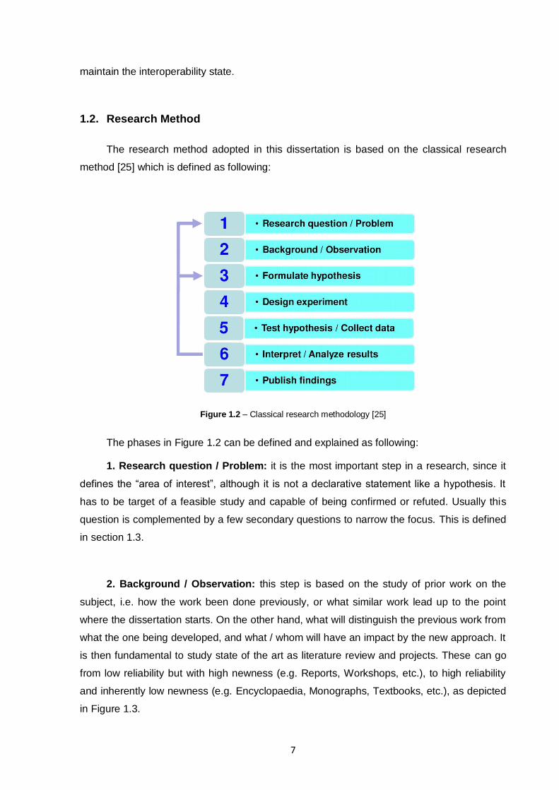
1.2. Research Method
The research method adopted in this dissertation is based on the classical research
method [25] which is defined as following:
Figure 1.2 – Classical research methodology [25]
The phases in Figure 1.2 can be defined and explained as following:
1. Research question / Problem: it is the most important step in a research, since it
defines the “area of interest”, although it is not a declarative statement like a hypothesis. It
has to be target of a feasible study and capable of being confirmed or refuted. Usually this
question is complemented by a few secondary questions to narrow the focus. This is defined
in section 1.3.
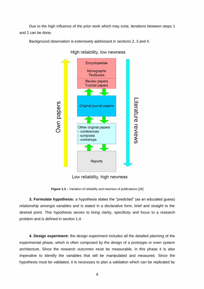
2. Background / Observation: this step is based on the study of prior work on the
subject, i.e. how the work been done previously, or what similar work lead up to the point
where the dissertation starts. On the other hand, what will distinguish the previous work from
what the one being developed, and what / whom will have an impact by the new approach. It
is then fundamental to study state of the art as literature review and projects. These can go
from low reliability but with high newness (e.g. Reports, Workshops, etc.), to high reliability
and inherently low newness (e.g. Encyclopaedia, Monographs, Textbooks, etc.), as depicted
in Figure 1.3.
8
Due to the high influence of the prior work which may exist, iterations between steps 1
and 2 can be done.
Background observation is extensively addressed in sections 2, 3 and 4.
Figure 1.3 – Variation of reliability and newness of publications [26]
3. Formulate hypothesis: a hypothesis states the “predicted” (as an educated guess)
relationship amongst variables and is stated in a declarative form, brief and straight to the
desired point. This hypothesis serves to bring clarity, specificity and focus to a research
problem and is defined in section 1.4.
4. Design experiment: the design experiment includes all the detailed planning of the
experimental phase, which is often composed by the design of a prototype or even system
architecture. Since the research outcomes must be measurable, in this phase it is also
imperative to identify the variables that will be manipulated and measured. Since the
hypothesis must be validated, it is necessary to plan a validation which can be replicated by

9
others in a feasible way. Theoretical design and proof-of-concept implementation are defined
in sections 5 and 6, respectively.
5. Test hypothesis / Collect data: to evaluate the hypothesis proposed, it is
necessary to evaluate the outcomes of the system / architecture designed. For this, a test
battery should be defined and applied to it, and further simulation if necessary, applying
possible multiple scenarios. For each test, data should be collected for further analysis and
hypothesis validation. Addressing this matter, section 7.1 defines the testing methodology
used to evaluate the proof-of-concept implementation.
6. Interpret / Analyse results: after all tests applied and data outputs collected, it is
time to interpret and analyse the results. If applicable, qualitative and quantitative (e.g.
descriptive and inferential statistics, clustering, etc.) data analysis should be applied to the
results. These can lead to weakening of the confidence of the hypothesis, or even put in
jeopardy all of the assumptions made in the very beginning of the research. This should not
be interpreted has a failure, but as a way to improve the original approach and try another
one with new expertise of the subject, re-iterating from step 1 or 2.
On the other hand, this is the step where, when positive results are attained, is possible
to consider the future and define the recommendations for further research. Discussion
regarding literature, research objectives and questions should be taken into account, and
draw conclusions out of it.
Interpretation and analysis of results from the proof-of-concept implementation are
presented in sections 7.2, 7.3, and 7.4.
7. Publish findings: the outcome of solids results (either in line of the original
hypothesis or against it) should result in a contribution to the scientific community.
Accordingly to the type of research, scientific papers should be written to present
intermediate results (e.g. in conferences), consolidated results (e.g. in journals), and finalised
with a dissertation about the hypothesis.
Scientific validation and hypothesis verification is presented in section 7.5.

10
1.3. Research Problem and Question(s)
How can enterprises effectively collaborate without having to adapt their internal
systems to each member of their business network?
o How can information models be dynamically integrated enabling
transparent interoperability between heterogeneous enterprises?
o Can model morphisms be independent of technological details in order
to be specified at management levels?
1.4. Hypothesis
By creating a common conceptual meta-model for systems information models,
one is able to abstract from technological details and enable the establishment
of semantic and structural morphisms, thus enabling network interoperability.
1.5. Dissertation Outline
In this section the current collaboration needs of enterprises and context of the
contribution of this dissertation are presented, evidencing the need for new solutions to
decrease the interoperability costs and entropy needed for sustainable enterprises
collaboration.
Sections 2, 3 and 4 present the grand topics of background observation. Section 2
covers models and modelling languages, addressed in a bottom up perspective, covering the
basis for modelling paradigms, model based standards and modelling languages. Section 3
takes this model basis to an upper level, by defining how models can be morphed and
mapped between them, without covering a technology which implements these morphisms.
Finally in section 4, interoperability framework solutions are addressed based on automated
model morphisms, defining various levels of interoperability and automatism, as well as the
technology available to implement an interoperability framework.
Section 5 defines a framework to achieve model and language interoperability in
business networks and a Central Meta-Model which enables the framework. It is based on
MDI and MDA technology, using the grand topics of background observation. A proof-of-
concept implementation steps are then presented in section 6, having a special focus on the
EXPRESS modelling language and enabling it in the framework. To validate both proof-of-
concept implementation and the proposed framework, section 7 defines and implements a

11
hybrid functional and non-functional testing methodology, and informs about the external
scientific validation of the framework.
Finally, in section 8 the conclusions and future work topics are presented.

12
13
2. INFORMATION MODELLING AND LANGUAGES
Information modelling is defined by the construction of computer-based symbol
structures, such as items, groups and relations which are able to capture and express the
meaning of information, knowledge or system and organize it in a precise format which not
only makes it understandable and useful to people [27] [28], but also able to be executed (if
the language is able to be executed). An executable modelling language can amplify the
productivity of skilled programmers, enabling them to address more complex and challenging
problems, less focusing the code writing and more about the functional services which the
system must provide. Given that information is becoming an ubiquitous, abundant and a
precious resource, its modelling is serving as a core technology for information systems
engineering, and with it modelling and simulation are quickly becoming the primary enablers
for complex system design [29], since they can represent knowledge in an intricate and
complex way and at various abstraction levels to allow automated analysis.
2.1. Models and Meta-Models
A model is a definition of some slice of reality which is being observed and interpreted,
which is constructed through the use of abstract elements and relationships in order to match
corresponding real elements and relationships. In some contexts (like Model Driven
Development / Engineering – MDD / MDE), the reality / object in study is called System
Under Study (SUS), defining the elements that exist in the system. Nevertheless, models can
represent different aspects of one reality, derive from different natures or be created using
different languages, paradigms, concepts and formalism levels [30].
Models must be written in a well defined modelling language, since the symbols and
relationships that are used to model a SUS should support the unification principle, described
both syntactic and semantically in a fixed and coherent way. The modelling language, in its
turn, is described by a meta-model – a model specifying constructs and relationships used in
a given modelling language, which makes solid defined statements about what can be
expressed in a valid model of that particular modelling language. Hence, a valid model is
only conformant to its meta-model, which is an imperative condition, when it does not violate
any statement and constructs inherited or deducible from its meta-model.
On the other hand, a meta-model is also approached as a model, which must also be
written in a coherent language – the meta-language. The latter, is considered to be
responsible to describe modelling languages in the same way of the meta-language / model

14
relation, but applied to the definition of statements of statements.
Figure 2.1 – Relationship between models, meta-models, modelling languages and SUS
As depicted on Figure 2.1 a model describing a SUS is written in a modelling language
which is conform to the semantics and syntax provided by its meta-model, and finally, the
latter is written according to its meta-language.
A reflexive meta-model prevents the indefinitely increase of abstraction layers (model,
language, meta-model and meta-languages layers), since it is expressed using the minimal
set of elements of the modelling language to express the statements of the meta-model. This
way, a meta-model is a self-describing model which self-conforms to its own semantics. A
few examples of reflexive meta-models are OMG‟s Meta Object Facility (MOF) [31], and
Ecore, which has been introduced with the Eclipse Modelling Framework (EMF) [32].
These relations between the multiple components of a modelling language was
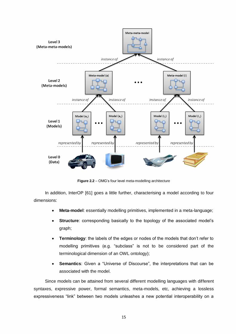
approached by the OMG‟s Model Driven Architecture (MDA), which considers that a model
must be an instance of a well-defined meta-model, and can be classified according to the
meta-modelling level they belong to. To confine the number of modelling layers to a
manageable number, OMG has specified a reference meta-modelling architecture, limiting
this number to four (see Figure 2.2). With this, is finally possible to perform operations on
different models:
Level 0 – model level that is not possible to instantiate, it is called in various
ways such as instance level or ground level (e.g. instances);
Level 1 – model level that has to be instantiated to obtain ground instances
(e.g., UML model);
Level 2 – known as the meta-model and describes the language itself (e.g.,
UML language);
Level 3 – meta-meta-model, where models are the base for generating different
languages (e.g., MOF).
15
Figure 2.2 – OMG‟s four level meta-modelling architecture
In addition, InterOP [61] goes a little further, characterising a model according to four
dimensions:
Meta-model: essentially modelling primitives, implemented in a meta-language;
Structure: corresponding basically to the topology of the associated model‟s
graph;
Terminology: the labels of the edges or nodes of the models that don‟t refer to
modelling primitives (e.g. “subclass” is not to be considered part of the
terminological dimension of an OWL ontology);
Semantics: Given a “Universe of Discourse”, the interpretations that can be
associated with the model.
Since models can be attained from several different modelling languages with different
syntaxes, expressive power, formal semantics, meta-models, etc, achieving a lossless
expressiveness “link” between two models unleashes a new potential interoperability on a
16
heterogeneous community.
2.2. Modelling Paradigms
Models and modelling is not a recent matter of engineering, since the discussion of the
effectiveness of models is taken into consideration and traced back to the oldest known
engineering textbook, by a Roman engineer from the first century B.C. [33].
Since modelling is a process of inquiry with intrinsic similarities with classis scientific
theory construction, data modelling can‟t avoid philosophical assumptions. By applying a
data model to information, systems or simply to some slice of reality, a philosophical analysis
can be applied. On the other hand, there is a continuum between two radically conflicting
views of the ontological nature of the data being modelled: the objectivist and the subjectivist
extremes [28]. In the latter, a paradigm is characterised by the ontological and
epistemological assumptions which are broad enough to the development of several practical
approaches of data modelling within each one, such as Entity-Relationship, object-oriented
languages or even LEGally Oriented Language (LEGOL) [34].
There are two basic ontological positions concerned with the modelled information,
which are concerned with the nature of the modelled information:
Realism, postulates that empirical entities objectively given as immutable
objects and structures of which the models are comprised, and the modelled
information exists whatever the observer uses it or not. In realism, the real
world exists and it is external and independent of the human / observer
experience of it [35];
Nominalism, on the other hand, postulates that reality is a subjective
construction of the mind and it is perceived and structured by socially
transmitted concepts and names, hence, the construction of reality varies with
the languages and cultures. In this view, there is no existence of an external
reality, it is only in the mind of the observer and knowledge does not exist
without the observer [36].
Epistemological assumptions define another two positions, which concern both with the
nature of knowledge of the modelled information, and how it is acquired:
Positivism, which explains the observable phenomena through the
identification of causal relationships, i.e. information is constructed in the
direction of a causal model which governs the observed sequence of
17
phenomena;
On the other hand, interpretivism approach denies the appropriateness of the
casual model, holding that the data modeller must depend on his socially
preconditioned and pre-understanding of the subject matter. By defending that
knowledge can only be improved by applying the point of view of individuals
directly involved on it, it is historically relevant to the frame of reference of both
the data modeller and the individuals directly involved [28].
The epistemological and ontological dimensions give four possible paradigms by
combination, where only two are primary significant for data modelling. While the first is
based on a realist-positivist position, which defines an objectivist paradigm, the latter is
based on a nominalist-interpretivist position, which defines a subjectivist paradigm.
Therefore, any data modelling techniques can be located somewhere along the region
between subjectivism and objectivism (in some literature “subjectivism” can also be referred
as “constructivism”) [35] [36].
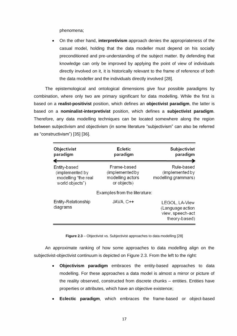
Figure 2.3 – Objectivist vs. Subjectivist approaches to data modelling [28]
An approximate ranking of how some approaches to data modelling align on the
subjectivist-objectivist continuum is depicted on Figure 2.3. From the left to the right:
Objectivism paradigm embraces the entity-based approaches to data
modelling. For these approaches a data model is almost a mirror or picture of
the reality observed, constructed from discrete chunks – entities. Entities have
properties or attributes, which have an objective existence;
Eclectic paradigm, which embraces the frame-based or object-based
18
approaches. The idea is that one combines a description of data and processes
it into a knowledge „frame‟, or „object‟. Frame-based approaches can be used to
implement either subjectivist or objectivist interpretations of data, but is also
possible to conceive them as predisposed towards subjectivism, since it difficult
to define its contents and there are no objective rules to accomplish it. Unlike
entities, sometimes frames are not perceived to exist in the observed reality as
objective facts;
Subjectivist paradigm embraces the rule-based approaches, since these are
heavily influenced by the subjectivist tradition. Its supporters see the data
modelling as formalising the meaning of messages which are exchanged
between professional communities. Since the expression of meanings must
follow socially determined rules in order to facilitate the comprehension of what
is being communicated, its supporters defend that meaning is created within the
human mind and related to human purpose or intensions. Being the latter arisen
from a socially constructed understanding of reality, emerging from social
interaction and condition by social conventions / rules, they state that all
computer data ultimately have to be interpreted in terms of their natural
language meanings. Hence data can at best convey meaning from someone to
someone, but no objective meaning can be had [28].
2.3. Data Standards
Many of the systems implemented across different enterprises and even departments
of the same enterprise were initially developed to function as stand-alone systems, therefore,
have limited or no capability to share and exchange information [37]. This happens because
each application typically uses a proprietary data model and stores data in closed proprietary
formats, limiting the share of this information with other software applications. To overcome
interoperability problems, IT experts typically have to translate the data from one
representation and format to another. This translation process involves many time-
consuming and error-prone programming. Experience shows that the use of proprietary data
models and formats has created many obstacles to improving availability, quality and
reusability of data. To address this matter, by standardising data models would help define
common and consistent data structures and semantics using vendor- and technology-neutral
data encoding and exchange formats. On the other hand, a standard data model would also
provide an integrated schema for representing and exchanging data across all asset life-
cycle phases [37].
19
Dedicated to serious standard definitions multiple organisations with different
application ranges exist, such as:
International Organization for Standardization (ISO) [38];
International Telecommunication Union (ITU-T) [39];
International Electrotechnical Commission (IEC) [40];
Open Applications Group (OAGi) [41];
Organization for the Advancement of Structured Information Standards (OASIS)
[42];
Object Management Group (OMG) [43];
World Wide Web Consortium (W3C) [44].
2.3.1. STEP
ISO has been pushing forward the development of standards and models [38]. Efforts
like STandard for the Exchange of Product Data (STEP) [45], have tried to deal with
integration and interoperability issues.
STEP is a family of standards for the computer-interpretable representation of product
information and for the exchange of product data under the manufacturing domain. It defines
a framework which provides neutral mechanisms that are capable of describing products
throughout their life cycle. The extent of standards required to support all the detailed
characteristics of systems in the PLC, leads to highly complex models, i.e. Application
Protocols (APs). These, are the STEP foundations for data exchange, enabling direct
communication to be established among several stakeholders within an industrial sectors.
APs are described using EXPRESS (ISO 10303-11) [46], which is the STEP modelling
language.
STEP data (i.e. an instance population of an EXPRESS schema) is typically
exchanged using an ASCII character-based syntax defined in ISO 10303-21 (also known as
Part 21 of STEP [47]). However, the STEP Part 21 syntax lacks extensibility, is hard for
humans to read, computer-interpretable only by software supporting STEP (being the latter
very expensive), and in the bottom line EXPRESS is unknown to the majority of
programmers [1] [48]. For these reasons, it is difficult to motivate implementers to adopt
these standard APs, thus risking losing all the expertise and rich contents of their Application
Protocol models. ISO, to face this situation, is developing standards to bind EXPRESS
schemas and data in XML, UML and OWL, which are technologies that are more popular
20
and have better tools support.
Hence, for the representation of data corresponding to an EXPRESS schema, the
STEP Part 28 (ISO 10303-28) specifies the mapping of type definitions and element
declarations to XML Schema (XSD [49]), and the rules for encoding conforming data in XML
according to certain configuration directives [50]. STEP Part 25 (ISO 10303-25) has similar
purposes at the model specification level, detailing a mapping of EXPRESS constructs into
the UML Interchange Meta-model, i.e. the XMI standard [51] [1].
2.4. Modelling Languages
Modelling language are artificial languages designed such way that they define a
consistent set of rules to represent information, knowledge or systems in a structure. The
rules are used for interpretation of the meaning of components in the structure, which usually
represent real objects, interactions, behaviours or systems. There are countless modelling
languages, with completely different types (e.g., graphical, object-oriented, algebraic, etc),
but in the next sections a few relevant ones (in the context of interoperability) are going to be
addressed.
2.4.1. Unified Modelling Language
Unified Modelling Language (UML) [52] is currently OMG's most-used specification and
the de facto industry standard modelling language for visualising, specifying, and
documenting software systems. It combines techniques from data, business, object and
component modelling aspects throughout the software development life cycle, and across
different implementation technologies [53].
UML models can be represented both textually and graphically. The latter specifies
several diagram types, which can be classified into three categories: structure, behaviour
and model managing diagrams.
Structure diagrams describe the static application structure of the system
which is being modelled, also known as System Under Study (SUS). These are
the Class, Object, Component and Deployment diagrams.
Behaviour diagrams describe the dynamic behaviour of the SUS. Therefore
Use case, Sequence, Activity, Collaboration and State-chart diagrams, are the
behavioural representations of the SUS.
Model managing is assured by Packages, Subsystems and Models, which
21
describe how to organise and manage application modules.
Finally, as will be explained in section 4, UML is the core standard used to develop the
Platform Independent Model (PIM) and Platform Specific Model (PSM) in the context of
Model Driven Architecture (MDA). Besides its powerful modelling mechanisms, it has other
features that are essential in an MDA environment, such as extension mechanisms – the
UML Profiles, which are described in the next section.
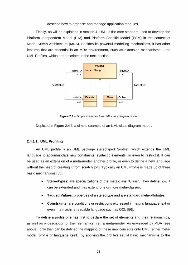
Figure 2.4 – Simple example of an UML class diagram model
Depicted in Figure 2.4 is a simple example of an UML class diagram model.
2.4.1.1. UML Profiling
An UML profile is an UML package stereotyped “profile”, which extends the UML
language to accommodate new constraints, syntactic elements, or even to restrict it. It can
be used as an extension of a meta-model, another profile, or even to define a new language
without the need of creating it from scratch [54]. Typically an UML Profile is made up of three
basic mechanisms [55]:
Stereotypes: are specializations of the meta-class “Class”. They define how it
can be extended and may extend one or more meta-classes;
Tagged Values: properties of a stereotype and are standard meta-attributes;
Constraints: are conditions or restrictions expressed in natural language text or
even in a machine readable language such as OCL [56].
To define a profile one has first to declare the set of elements and their relationships,
as well as a description of their semantics, i.e., a meta-model. As envisaged by MDA (see
above), only then can be defined the mapping of these new concepts onto UML (either meta-
model, profile or language itself), by applying the profile‟s set of basic mechanisms to the
22
meta-model, linking it to destination model basic constructs. Once the Profile is well defined,
an executable transformation language can be applied to it (e.g. ATLAS Transformation
Language – ATL) and achieve morphism automation from a model conforming to the defined
profiled meta-model. The final result is an UML model, which also conforms to the profile
created.
2.4.2. EXPRESS
EXPRESS (ISO 10303-11) [46] is a modelling language combining ideas from the
entity-attribute-relationship family of modelling languages with object modelling concepts. It is
used to describe the STEP information models in a textual format. It can represent complex
inheritance relationships and functions, and includes a rich set of constructs for specifying
constraints on populations of instances [57]. EXPRESS being mainly based in the entity-
attribute relationship model, but not limited to it, since encompasses several characteristics
from other languages such as C, C++, Pascal, SQL, etc. With this close bound with those
languages, it has an object-oriented flavour, inheritance mechanisms among the entities
constituting the conceptual model, and a large variety of types, thus becoming a very
powerful modelling language.
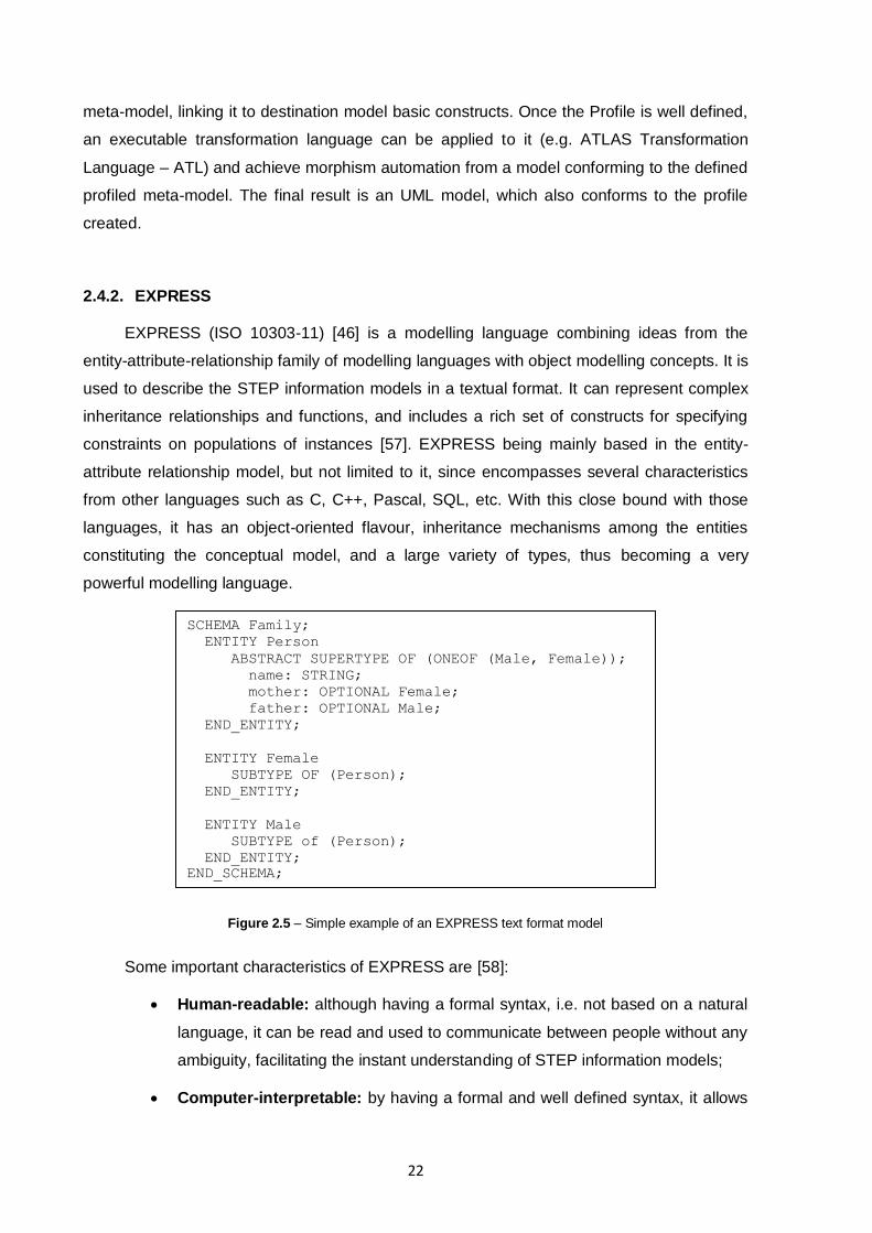
Figure 2.5 – Simple example of an EXPRESS text format model
Some important characteristics of EXPRESS are [58]:
Human-readable: although having a formal syntax, i.e. not based on a natural
language, it can be read and used to communicate between people without any
ambiguity, facilitating the instant understanding of STEP information models;
Computer-interpretable: by having a formal and well defined syntax, it allows
SCHEMA Family;
ENTITY Person
ABSTRACT SUPERTYPE OF (ONEOF (Male, Female));
name: STRING;
mother: OPTIONAL Female;
father: OPTIONAL Male;
END_ENTITY;
ENTITY Female
SUBTYPE OF (Person);
END_ENTITY;
ENTITY Male
SUBTYPE of (Person);
END_ENTITY;
END_SCHEMA;
23
its models to be processed by computer tools. With this is possible to validate
the conformance (i.e. realise conformance testing) of STEP-based messages,
which fundamental for successful communication [59]. With this, data
exchanged can be cross-checked with the respective information models, to
determine whether they are valid or not;
Technology and platform independent: EXPRESS is designed for
conceptual product data modelling, hence its information models are described
without any specific technology or implementation details, allowing them to be
mapped into any implementation form. This feature combined with the previous
one makes it possible to generate different software artefacts (e.g. software
code, database structure, etc) from the same information model.
A simple example of an EXPRESS model is depicted in Figure 2.5. The main
constructs which can be evidenced in the EXPRESS language are:
Schemas and Interface specifications: Schemas support the definition of
modular information models, i.e., every model consists of one or more
schemas, each with specific data definitions of a given scope. On the other
hand, the interface specifications (USE FROM and REFERENCE constructs)
enables data definitions defined in one schema to be visible in others;
Entities and attributes: Entities are the basic units for data definition in
EXPRESS, describing classes of real world with associated properties.
Properties are represented as attributes of the entities and depending on their
types they can be simple values (e.g. string, real, etc) or relationships to other
constructs (e.g. entity reference, redeclaration, refining type, etc);
Types: describe the domain of values that which an attribute can represent.
EXPRESS defines the basic built-in types (e.g. string, real, date, etc) but one
can define new types at the cost of the built-in types;
Constraint Rules: are constructs that allows the definition of restrictions for the
values and relationships among the data definitions in a schema. This allows
the definition of complex and intricate models, which can be checked for
conformance not only at the syntax level, but also at the semantic level.
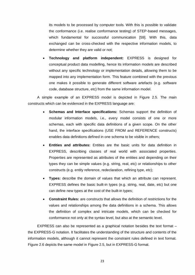
EXPRESS can also be represented as a graphical notation besides the text format –
the EXPRESS-G notation. It facilitates the understanding of the structure and contents of the
information models, although it cannot represent the constraint rules defined in text format.
Figure 2.6 depicts the same model in Figure 2.5, but in EXPRESS-G format.
24
Figure 2.6 – Simple example of an EXPRESS-G format model
2.4.3. Others
Besides UML and EXPRESS modelling languages, there are others broadly used for
multiple purposes. A few examples are:
XML Schema (XSD) [49] is a language for expressing constraints about XML
documents. There are several different schema languages in widespread use,
but the main ones are Document Type Definitions (DTDs), Relax-NG,
Schematron and W3C XSD (XML Schema Definitions), adding to XML the
ability to define element and attribute content as containing values such as
integers and dates rather than arbitrary text;
OWL 2 Web Ontology Language [60] is an ontology language for the
Semantic Web with formally defined meaning. Ontologies are formalized
vocabularies of terms, often covering a specific domain and shared by a
community of users. They specify the definitions of terms by describing their
relationships with other terms in the ontology. OWL 2 ontologies provide
classes, properties, individuals, and data values which are stored as Semantic
Web documents. It also uses datatypes defined in the XML Schema Definition
Language (XSD) and is a W3C recommendation since 27 October 2009.
25
3. MODEL MORPHISMS
Model Morphism, originally from mathematics, is the abstraction of a structure-
preserving process between two mathematical structures, but applied to data models [61]
[62]. This term only recently has been used in ICT systems and models, thus this new usage
of “morphism” has the same inherited concept. This new application was introduced by the
international research project INTEROP-NoE [63] with the aim of representing all kinds of,
unary or binary, operations (i.e. mapping, merging, transformation, composition or
abstraction) between two or more model specifications that may be described in different
languages. On the other hand, models can be approached as graphs, since graphs are well
suited to describe the underlying structures of models, especially transformations of visual
models which can be naturally formulated by graph transformations [64].
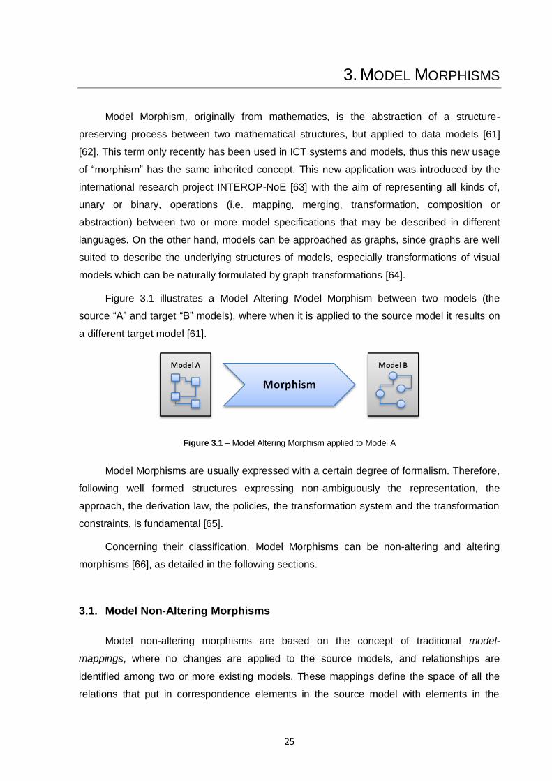
Figure 3.1 illustrates a Model Altering Model Morphism between two models (the
source “A” and target “B” models), where when it is applied to the source model it results on
a different target model [61].
Figure 3.1 – Model Altering Morphism applied to Model A
Model Morphisms are usually expressed with a certain degree of formalism. Therefore,
following well formed structures expressing non-ambiguously the representation, the
approach, the derivation law, the policies, the transformation system and the transformation
constraints, is fundamental [65].
Concerning their classification, Model Morphisms can be non-altering and altering
morphisms [66], as detailed in the following sections.
3.1. Model Non-Altering Morphisms
Model non-altering morphisms are based on the concept of traditional model-
mappings, where no changes are applied to the source models, and relationships are
identified among two or more existing models. These mappings define the space of all the
relations that put in correspondence elements in the source model with elements in the
26
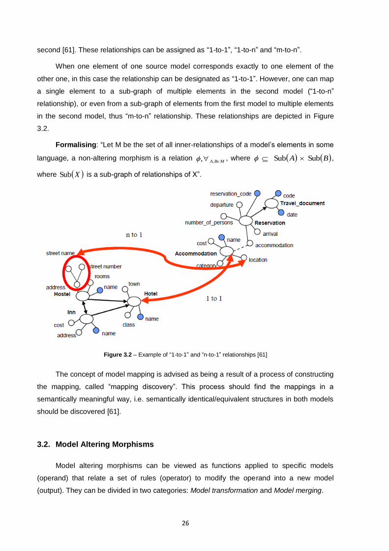
second [61]. These relationships can be assigned as “1-to-1”, “1-to-n” and “m-to-n”.
When one element of one source model corresponds exactly to one element of the
other one, in this case the relationship can be designated as “1-to-1”. However, one can map
a single element to a sub-graph of multiple elements in the second model (“1-to-n”
relationship), or even from a sub-graph of elements from the first model to multiple elements
in the second model, thus “m-to-n” relationship. These relationships are depicted in Figure
3.2.
Formalising: “Let M be the set of all inner-relationships of a model‟s elements in some
language, a non-altering morphism is a relation MBA ,, , where B A SubSub ,
where XSub is a sub-graph of relationships of X”.
Figure 3.2 – Example of “1-to-1” and “n-to-1” relationships [61]
The concept of model mapping is advised as being a result of a process of constructing
the mapping, called “mapping discovery”. This process should find the mappings in a
semantically meaningful way, i.e. semantically identical/equivalent structures in both models
should be discovered [61].
3.2. Model Altering Morphisms
Model altering morphisms can be viewed as functions applied to specific models
(operand) that relate a set of rules (operator) to modify the operand into a new model
(output). They can be divided in two categories: Model transformation and Model merging.
27
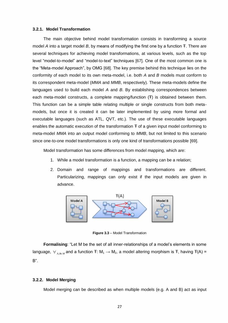
3.2.1. Model Transformation
The main objective behind model transformation consists in transforming a source
model A into a target model B, by means of modifying the first one by a function Ŧ. There are
several techniques for achieving model transformations, at various levels, such as the top
level “model-to-model” and “model-to-text” techniques [67]. One of the most common one is
the “Meta-model Approach”, by OMG [68]. The key premise behind this technique lies on the
conformity of each model to its own meta-model, i.e. both A and B models must conform to
its correspondent meta-model (MMA and MMB, respectively). These meta-models define the
languages used to build each model A and B. By establishing correspondences between
each meta-model constructs, a complete mapping/function (Ŧ) is obtained between them.
This function can be a simple table relating multiple or single constructs from both meta-
models, but once it is created it can be later implemented by using more formal and
executable languages (such as ATL, QVT, etc.). The use of these executable languages
enables the automatic execution of the transformation Ŧ of a given input model conforming to
meta-model MMA into an output model conforming to MMB, but not limited to this scenario
since one-to-one model transformations is only one kind of transformations possible [69].
Model transformation has some differences from model mapping, which are:
1. While a model transformation is a function, a mapping can be a relation;
2. Domain and range of mappings and transformations are different.
Particularizing, mappings can only exist if the input models are given in
advance.
Figure 3.3 – Model Transformation
Formalising: “Let M be the set of all inner-relationships of a model‟s elements in some
language, MBA ,
and a function Ŧ: M1 → M2, a model altering morphism is Ŧ, having Ŧ(A) =
B”.
3.2.2. Model Merging
Model merging can be described as when multiple models (e.g. A and B) act as input
28
for the model transformation, but preserving all original semantics from the input models.
This means that there is no fundamental difference in considering multiple input models as a
unique aggregated model, a set of disjoint graphs, one for each input model, which are
joined through a mechanism of multiple inputs and a single output [61].
Formalising: “Let M be the set of all inner-relationships of a model‟s elements in some
language, MCBA ,,
and a function Ŧ: (M1,M2) → M3, a model altering morphism is Ŧ, having
Ŧ(A,B) = C”.
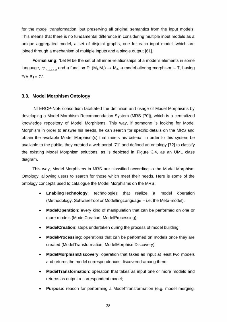
3.3. Model Morphism Ontology
INTEROP-NoE consortium facilitated the definition and usage of Model Morphisms by
developing a Model Morphism Recommendation System (MRS [70]), which is a centralized
knowledge repository of Model Morphisms. This way, if someone is looking for Model
Morphism in order to answer his needs, he can search for specific details on the MRS and
obtain the available Model Morphism(s) that meets his criteria. In order to this system be
available to the public, they created a web portal [71] and defined an ontology [72] to classify
the existing Model Morphism solutions, as is depicted in Figure 3.4, as an UML class
diagram.
This way, Model Morphisms in MRS are classified according to the Model Morphism
Ontology, allowing users to search for those which meet their needs. Here is some of the
ontology concepts used to catalogue the Model Morphisms on the MRS:
EnablingTechnology: technologies that realize a model operation
(Methodology, SoftwareTool or ModellingLanguage – i.e. the Meta-model);
ModelOperation: every kind of manipulation that can be performed on one or
more models (ModelCreation, ModelProcessing);
ModelCreation: steps undertaken during the process of model building;
ModelProcessing: operations that can be performed on models once they are
created (ModelTransformation, ModelMorphismDiscovery);
ModelMorphismDiscovery: operation that takes as input at least two models
and returns the model correspondences discovered among them;
ModelTransformation: operation that takes as input one or more models and
returns as output a correspondent model;
Purpose: reason for performing a ModelTransformation (e.g. model merging,
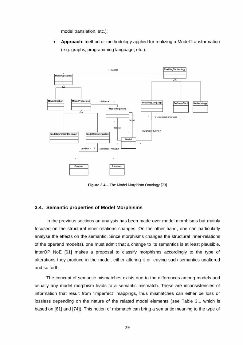
29
model translation, etc.);
Approach: method or methodology applied for realizing a ModelTransformation
(e.g. graphs, programming language, etc.).
Figure 3.4 – The Model Morphism Ontology [73]
3.4. Semantic properties of Model Morphisms
In the previous sections an analysis has been made over model morphisms but mainly
focused on the structural inner-relations changes. On the other hand, one can particularly
analyse the effects on the semantic. Since morphisms changes the structural inner-relations
of the operand model(s), one must admit that a change to its semantics is at least plausible.
InterOP NoE [61] makes a proposal to classify morphisms accordingly to the type of
alterations they produce in the model, either altering it or leaving such semantics unaltered
and so forth.
The concept of semantic mismatches exists due to the differences among models and
usually any model morphism leads to a semantic mismatch. These are inconsistencies of
information that result from “imperfect” mappings, thus mismatches can either be loss or
lossless depending on the nature of the related model elements (see Table 3.1 which is
based on [61] and [74]). This notion of mismatch can bring a semantic meaning to the type of
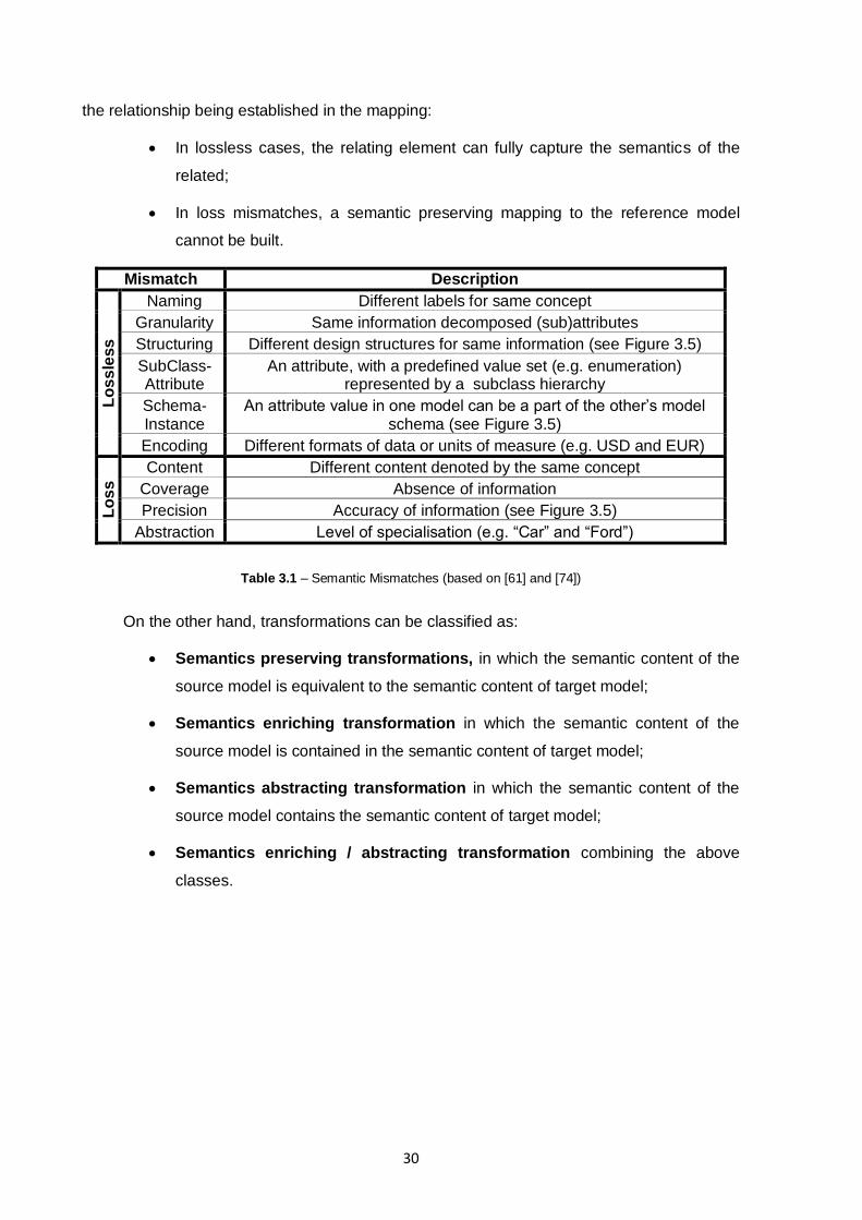
30
the relationship being established in the mapping:
In lossless cases, the relating element can fully capture the semantics of the
related;
In loss mismatches, a semantic preserving mapping to the reference model
cannot be built.
Mismatch Description
Lo
ss
less
Naming Different labels for same concept
Granularity Same information decomposed (sub)attributes
Structuring Different design structures for same information (see Figure 3.5)
SubClass-Attribute
An attribute, with a predefined value set (e.g. enumeration) represented by a subclass hierarchy
Schema-Instance
An attribute value in one model can be a part of the other‟s model schema (see Figure 3.5)
Encoding Different formats of data or units of measure (e.g. USD and EUR)
Lo
ss
Content Different content denoted by the same concept
Coverage Absence of information
Precision Accuracy of information (see Figure 3.5)
Abstraction Level of specialisation (e.g. “Car” and “Ford”)
Table 3.1 – Semantic Mismatches (based on [61] and [74])
On the other hand, transformations can be classified as:
Semantics preserving transformations, in which the semantic content of the
source model is equivalent to the semantic content of target model;
Semantics enriching transformation in which the semantic content of the
source model is contained in the semantic content of target model;
Semantics abstracting transformation in which the semantic content of the
source model contains the semantic content of target model;
Semantics enriching / abstracting transformation combining the above
classes.
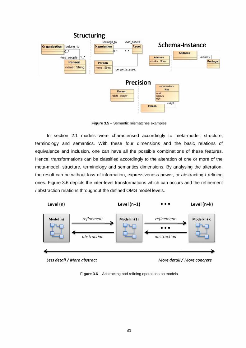
31
Figure 3.5 – Semantic mismatches examples
In section 2.1 models were characterised accordingly to meta-model, structure,
terminology and semantics. With these four dimensions and the basic relations of
equivalence and inclusion, one can have all the possible combinations of these features.
Hence, transformations can be classified accordingly to the alteration of one or more of the
meta-model, structure, terminology and semantics dimensions. By analysing the alteration,
the result can be without loss of information, expressiveness power, or abstracting / refining
ones. Figure 3.6 depicts the inter-level transformations which can occurs and the refinement
/ abstraction relations throughout the defined OMG model levels.
Figure 3.6 – Abstracting and refining operations on models

32

33
4. MODEL DRIVEN INTEROPERABILITY FOUNDATIONS
Model Driven Development (MDD), sometimes also referred as Model Driven
Engineering (MDE), is an emerging practice for developing model driven applications. Its
defining characteristic is that software development focus on models rather than computer
program functionalities [75]. This way it is possible to express information models using
concepts that are less bound to the underlying implementation technology and closer to the
problem domain relative to most popular programming languages. When compared to these,
models are easier to specify, verify, understand and maintain, thus widening the creation of
new systems to domain experts, instead of only computing specialists to do so. One key
premise behind MDD is that code can be automatically generated from the corresponding
models, elevating, once more, the level of abstraction at which developers operate, reducing
both the amount of development effort and the complexity of the software artefacts that the
developers use [76].
Since the past two decades, level of software abstraction has been raised, for example,
by using more expressive object-oriented languages (JAVA, C#, C++, etc), rather than less
abstract Fortran or C [77]. MDD‟s vision does it again, by invoking a unification principle –
“everything is a model”, the same way that the object-oriented languages invokes that
“everything is an object”. Thus, the need for increase of software abstraction is not new, and
MDD beside being the latest approach to do so, it introduces model abstractions at the
various stages of the software life cycle, representing an evolutionary step of past efforts to
create methods, languages and technologies to further elevate the abstraction level and
increase the productivity and quality of the software development process [58] [78] [79].
Another key feature in MDD is the support of model at different levels of abstraction,
from the high-level models focusing on goals, roles and responsibilities, to the bottom-level
use-cases and scenarios for business execution. Supporting these principles can only be
attained through mechanisms that perform operation on models and ensure traceability and
consistency between them throughout the different levels of abstraction [58] [80].
4.1. Model Driven Interoperability Method
Model Driven Interoperability (MDI) Method is a model-driven method, based
essentially on Model Driven Architecture (MDA) approach, to solve interoperability problems
between enterprises not only at the application and software systems level, but also at the
Enterprise Modelling level with an ontological support. This method aims at improving the
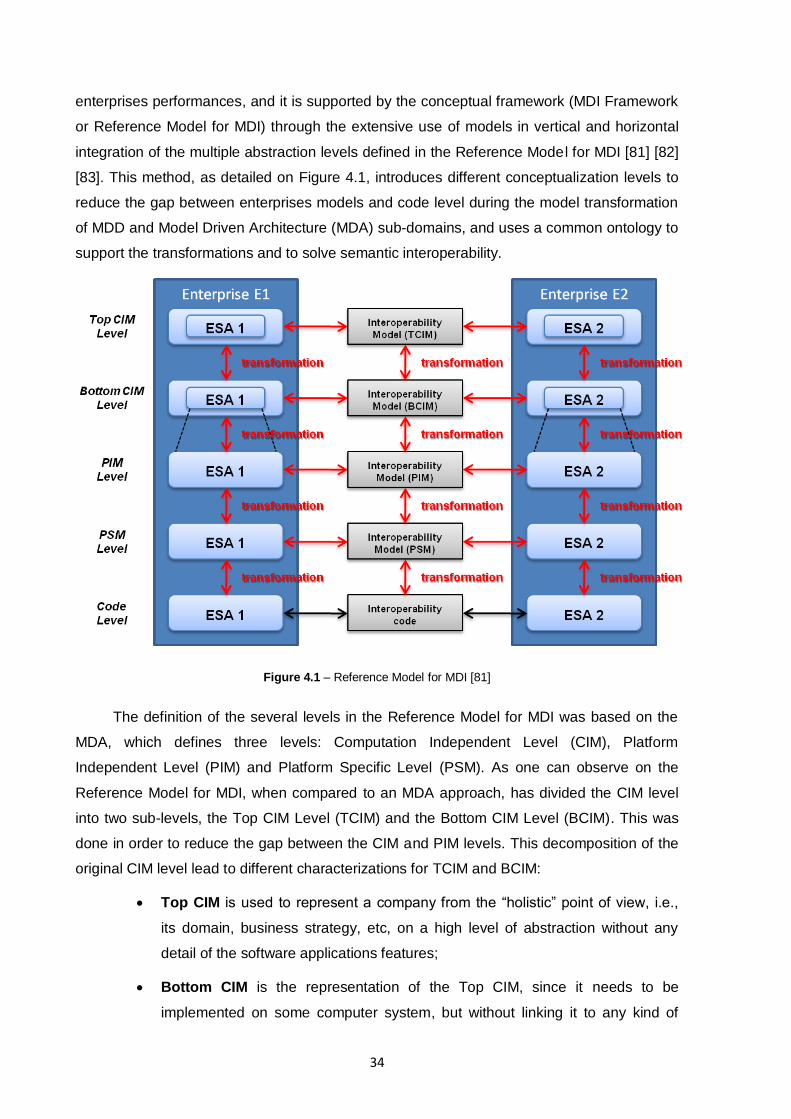
34
enterprises performances, and it is supported by the conceptual framework (MDI Framework
or Reference Model for MDI) through the extensive use of models in vertical and horizontal
integration of the multiple abstraction levels defined in the Reference Model for MDI [81] [82]
[83]. This method, as detailed on Figure 4.1, introduces different conceptualization levels to
reduce the gap between enterprises models and code level during the model transformation
of MDD and Model Driven Architecture (MDA) sub-domains, and uses a common ontology to
support the transformations and to solve semantic interoperability.
Figure 4.1 – Reference Model for MDI [81]
The definition of the several levels in the Reference Model for MDI was based on the
MDA, which defines three levels: Computation Independent Level (CIM), Platform
Independent Level (PIM) and Platform Specific Level (PSM). As one can observe on the
Reference Model for MDI, when compared to an MDA approach, has divided the CIM level
into two sub-levels, the Top CIM Level (TCIM) and the Bottom CIM Level (BCIM). This was
done in order to reduce the gap between the CIM and PIM levels. This decomposition of the
original CIM level lead to different characterizations for TCIM and BCIM:
Top CIM is used to represent a company from the “holistic” point of view, i.e.,
its domain, business strategy, etc, on a high level of abstraction without any
detail of the software applications features;
Bottom CIM is the representation of the Top CIM, since it needs to be
implemented on some computer system, but without linking it to any kind of
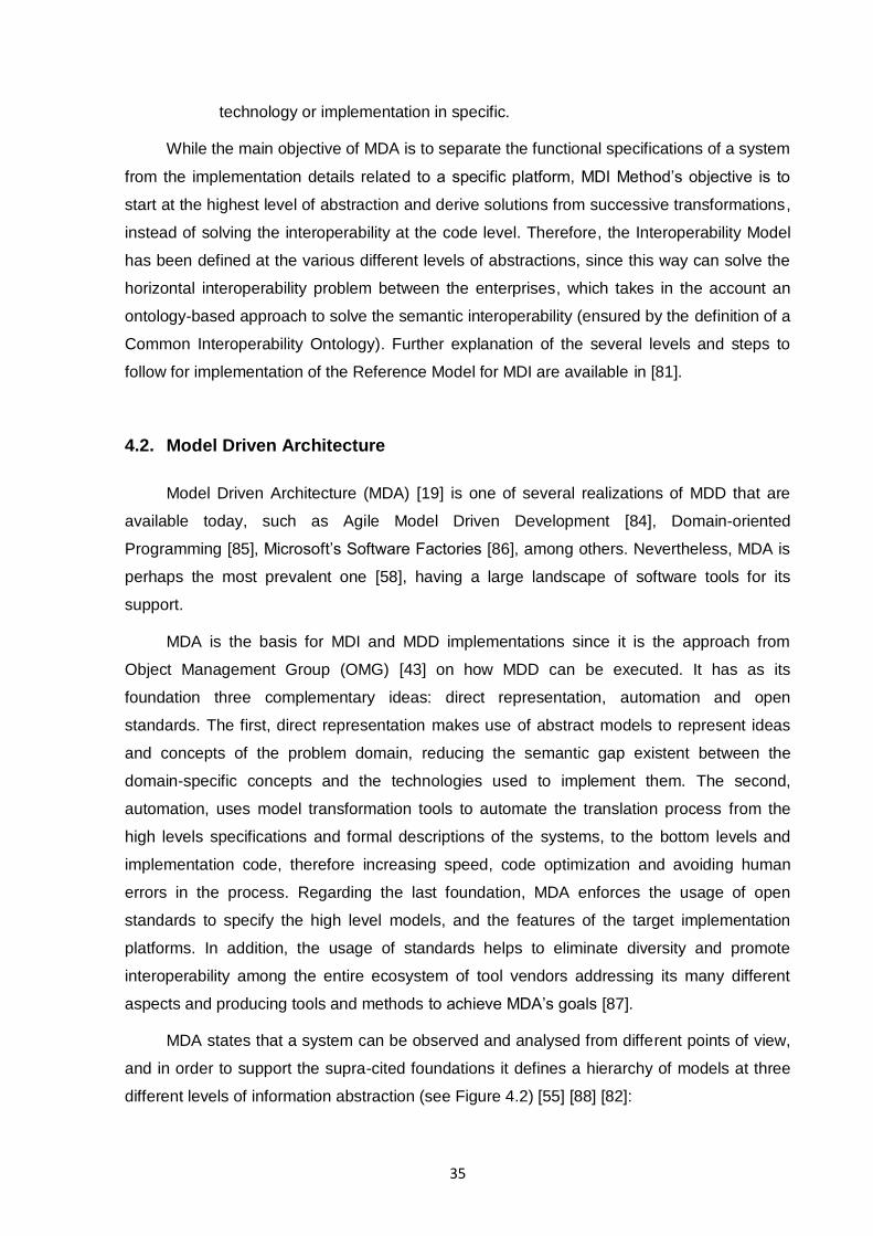
35
technology or implementation in specific.
While the main objective of MDA is to separate the functional specifications of a system
from the implementation details related to a specific platform, MDI Method‟s objective is to
start at the highest level of abstraction and derive solutions from successive transformations,
instead of solving the interoperability at the code level. Therefore, the Interoperability Model
has been defined at the various different levels of abstractions, since this way can solve the
horizontal interoperability problem between the enterprises, which takes in the account an
ontology-based approach to solve the semantic interoperability (ensured by the definition of a
Common Interoperability Ontology). Further explanation of the several levels and steps to
follow for implementation of the Reference Model for MDI are available in [81].
4.2. Model Driven Architecture
Model Driven Architecture (MDA) [19] is one of several realizations of MDD that are
available today, such as Agile Model Driven Development [84], Domain-oriented
Programming [85], Microsoft‟s Software Factories [86], among others. Nevertheless, MDA is
perhaps the most prevalent one [58], having a large landscape of software tools for its
support.
MDA is the basis for MDI and MDD implementations since it is the approach from
Object Management Group (OMG) [43] on how MDD can be executed. It has as its
foundation three complementary ideas: direct representation, automation and open
standards. The first, direct representation makes use of abstract models to represent ideas
and concepts of the problem domain, reducing the semantic gap existent between the
domain-specific concepts and the technologies used to implement them. The second,
automation, uses model transformation tools to automate the translation process from the
high levels specifications and formal descriptions of the systems, to the bottom levels and
implementation code, therefore increasing speed, code optimization and avoiding human
errors in the process. Regarding the last foundation, MDA enforces the usage of open
standards to specify the high level models, and the features of the target implementation
platforms. In addition, the usage of standards helps to eliminate diversity and promote
interoperability among the entire ecosystem of tool vendors addressing its many different
aspects and producing tools and methods to achieve MDA‟s goals [87].
MDA states that a system can be observed and analysed from different points of view,
and in order to support the supra-cited foundations it defines a hierarchy of models at three
different levels of information abstraction (see Figure 4.2) [55] [88] [82]:
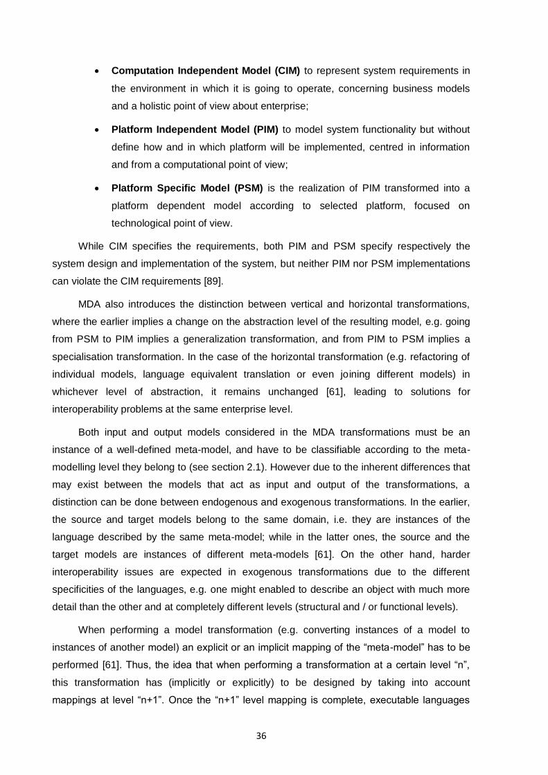
36
Computation Independent Model (CIM) to represent system requirements in
the environment in which it is going to operate, concerning business models
and a holistic point of view about enterprise;
Platform Independent Model (PIM) to model system functionality but without
define how and in which platform will be implemented, centred in information
and from a computational point of view;
Platform Specific Model (PSM) is the realization of PIM transformed into a
platform dependent model according to selected platform, focused on
technological point of view.
While CIM specifies the requirements, both PIM and PSM specify respectively the
system design and implementation of the system, but neither PIM nor PSM implementations
can violate the CIM requirements [89].
MDA also introduces the distinction between vertical and horizontal transformations,
where the earlier implies a change on the abstraction level of the resulting model, e.g. going
from PSM to PIM implies a generalization transformation, and from PIM to PSM implies a
specialisation transformation. In the case of the horizontal transformation (e.g. refactoring of
individual models, language equivalent translation or even joining different models) in
whichever level of abstraction, it remains unchanged [61], leading to solutions for
interoperability problems at the same enterprise level.
Both input and output models considered in the MDA transformations must be an
instance of a well-defined meta-model, and have to be classifiable according to the meta-
modelling level they belong to (see section 2.1). However due to the inherent differences that
may exist between the models that act as input and output of the transformations, a
distinction can be done between endogenous and exogenous transformations. In the earlier,
the source and target models belong to the same domain, i.e. they are instances of the
language described by the same meta-model; while in the latter ones, the source and the
target models are instances of different meta-models [61]. On the other hand, harder
interoperability issues are expected in exogenous transformations due to the different
specificities of the languages, e.g. one might enabled to describe an object with much more
detail than the other and at completely different levels (structural and / or functional levels).
When performing a model transformation (e.g. converting instances of a model to
instances of another model) an explicit or an implicit mapping of the “meta-model” has to be
performed [61]. Thus, the idea that when performing a transformation at a certain level “n”,
this transformation has (implicitly or explicitly) to be designed by taking into account
mappings at level “n+1”. Once the “n+1” level mapping is complete, executable languages
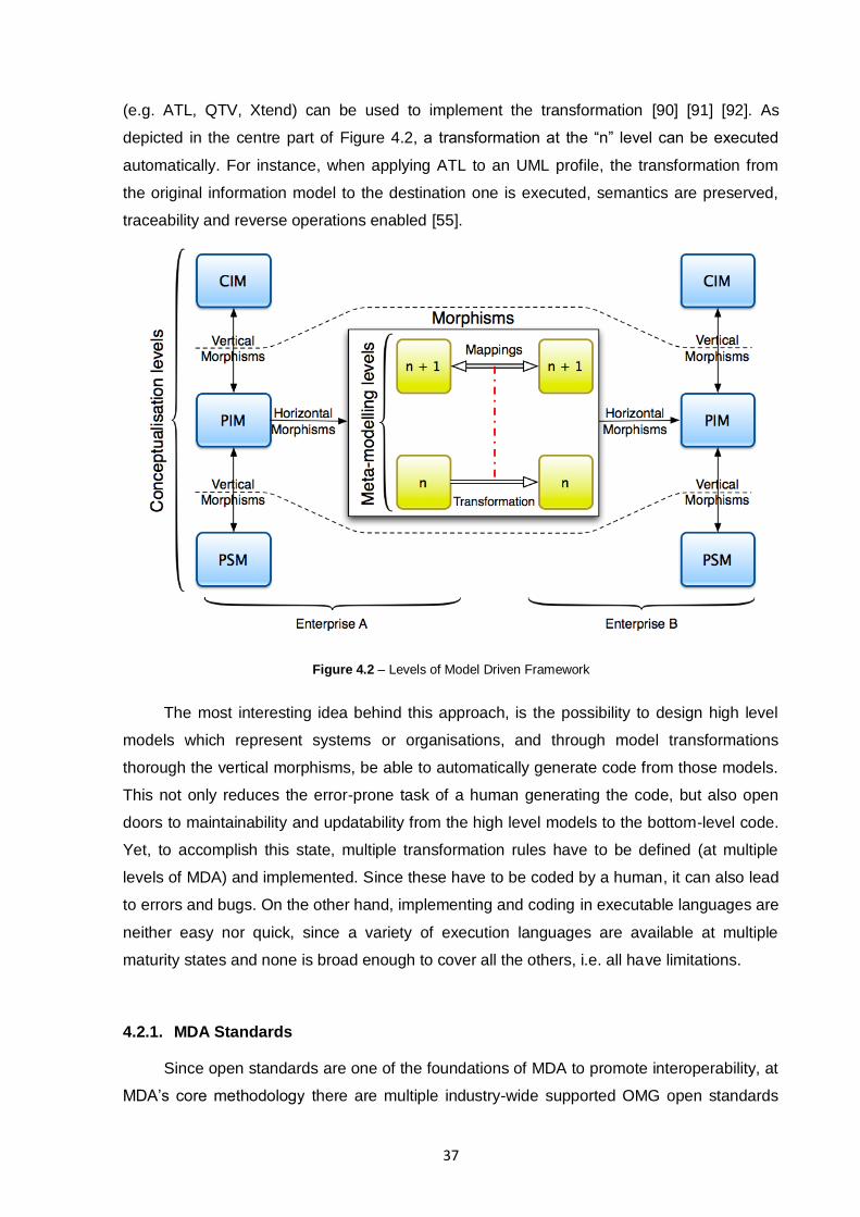
37
(e.g. ATL, QTV, Xtend) can be used to implement the transformation [90] [91] [92]. As
depicted in the centre part of Figure 4.2, a transformation at the “n” level can be executed
automatically. For instance, when applying ATL to an UML profile, the transformation from
the original information model to the destination one is executed, semantics are preserved,
traceability and reverse operations enabled [55].
Figure 4.2 – Levels of Model Driven Framework
The most interesting idea behind this approach, is the possibility to design high level
models which represent systems or organisations, and through model transformations
thorough the vertical morphisms, be able to automatically generate code from those models.
This not only reduces the error-prone task of a human generating the code, but also open
doors to maintainability and updatability from the high level models to the bottom-level code.
Yet, to accomplish this state, multiple transformation rules have to be defined (at multiple
levels of MDA) and implemented. Since these have to be coded by a human, it can also lead
to errors and bugs. On the other hand, implementing and coding in executable languages are
neither easy nor quick, since a variety of execution languages are available at multiple
maturity states and none is broad enough to cover all the others, i.e. all have limitations.
4.2.1. MDA Standards
Since open standards are one of the foundations of MDA to promote interoperability, at
MDA‟s core methodology there are multiple industry-wide supported OMG open standards

38
like UML (section 2.4.1), MOF and XMI. An instantiation of the OMG meta-modelling
reference architecture with some open standards is depicted on Figure 4.3.
Figure 4.3 – Instantiation of the OMG's meta-modelling architecture with MDA open standards
4.2.1.1. Meta-Object Facility
The Meta-Object Facility (MOF) [31] is an extensible model driven integration
framework for defining, manipulating and integrating metadata and data in a platform
independent manner. The OMG standard models, such as UML, are defined in terms of MOF
constructs, providing the basis for model/metadata interchange and interoperability, also
being the mechanism through which models are analysed in XMI [93].
Thus, MOF is the foundation of OMG's industry-standard environment, where models
can be exported from and to multiple applications, transported across a network, stored and
retrieved in a repository, rendered into multiple different formats (e.g. XMI), transformed, and
used to generate application code. These operations are not restricted to structural models,
or even to models defined in UML, since non-UML modelling languages can partake also, as
long as they are MOF-based, i.e. composed by the MOF constructs.
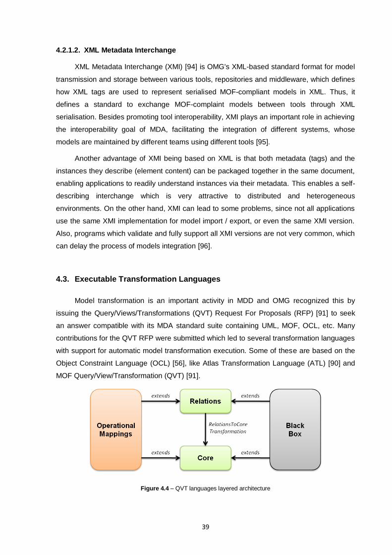
39
4.2.1.2. XML Metadata Interchange
XML Metadata Interchange (XMI) [94] is OMG's XML-based standard format for model
transmission and storage between various tools, repositories and middleware, which defines
how XML tags are used to represent serialised MOF-compliant models in XML. Thus, it
defines a standard to exchange MOF-complaint models between tools through XML
serialisation. Besides promoting tool interoperability, XMI plays an important role in achieving
the interoperability goal of MDA, facilitating the integration of different systems, whose
models are maintained by different teams using different tools [95].
Another advantage of XMI being based on XML is that both metadata (tags) and the
instances they describe (element content) can be packaged together in the same document,
enabling applications to readily understand instances via their metadata. This enables a self-
describing interchange which is very attractive to distributed and heterogeneous
environments. On the other hand, XMI can lead to some problems, since not all applications
use the same XMI implementation for model import / export, or even the same XMI version.
Also, programs which validate and fully support all XMI versions are not very common, which
can delay the process of models integration [96].
4.3. Executable Transformation Languages
Model transformation is an important activity in MDD and OMG recognized this by
issuing the Query/Views/Transformations (QVT) Request For Proposals (RFP) [91] to seek
an answer compatible with its MDA standard suite containing UML, MOF, OCL, etc. Many
contributions for the QVT RFP were submitted which led to several transformation languages
with support for automatic model transformation execution. Some of these are based on the
Object Constraint Language (OCL) [56], like Atlas Transformation Language (ATL) [90] and
MOF Query/View/Transformation (QVT) [91].
Figure 4.4 – QVT languages layered architecture
40
OMG‟s QVT defines a standard way to transform source models into target models,
which is sustained by the four levels of OMG‟s meta-modelling architecture (see Figure 2.2)
and its conforming relations. It also defines three domain-specific languages: Relations, Core
and Operational Mappings which are organised in a layered architecture, as depicted in
Figure 4.4:
The Relations language provides capabilities for specifying transformations as a
set of relations among models and handles the manipulation of traceability links
automatically, hiding the related details from the developer;
The Core language is simpler than the Relations language. One purpose of the
Core language is to provide the basis for specifying the semantics of the
Relations language. The semantics of the Relations language is given as the
transformation RelationsToCore. Since sometimes it is difficult to provide a
complete declarative solution to a given transformation problem and to address
this, the QVT proposes two mechanisms for extending the declarative
languages Relations and Core: a third language called Operational Mappings,
and a mechanism for invoking transformation functionality implemented in an
arbitrary language (Black Box implementation);
The Operational Mappings language extends the Relations language with
imperative constructs and OCL constructs. The idea in this language is that the
object patterns specified in the relations are instantiated by using imperative
constructs. In that way, the declaratively specified relations are imperatively
implemented in the language;
The Black Box mechanism allows the plugging-in and execution of external
code during the transformation execution, allowing complex algorithms to be
implemented in any programming language and enabling reuse of already
existing libraries.
Finally, QVT supports bidirectional transformations but allows model to model only
transformations, conforming to any MOF 2.0 meta-model. This means that text (e.g. XML,
code, SQL, etc) to model and vice-versa is out of QVT scope and simply not supported.
ATL was initially conceived as an answer to the QVT RFP but later the language
requirements evolved towards a larger set of transformational scenarios. Since ATL is
inspired in QVT, it led to a hybrid of declarative (through matched rules) and imperative
(called rules and action blocks) transformation language. The main difference between them
is that it can only be used to do unidirectional syntactic and semantic translation. An ATL
transformation is composed by a set of rules (matched rules) that define how the source
41
model elements are linked, navigated enabling and instantiating the elements of the target
model. These elements can then be filled with information from the source model by called
rules (similar to functions in usual object languages like JAVA) and action blocks (blocks of
imperative code which can be used by matched rules and called rules). ATL is one of the
most used transformation languages, having a large user base and being very well
documented, nevertheless it is neither a standard nor a simple language to use [97].
Beside ATL and QVT, several other languages exist, such as:
Non-MOF based VIATRA2 [98], GReAT [99], AGG [100] which were built upon
the strong foundation of graph transformations and were elaborated
independently of the OMG efforts;
Non-OCL based Xtend/Xpand [92] which is a JAVA looked-alike transformation
language, now a component of the open development platform Eclipse.
All the languages addressed in this section have some common goals and features,
but also expose differences in their paradigms, constructs, underlying modelling approaches,
etc. Despite the fact that they are designed as general-purpose model-to-model
transformation languages, all have strong and weak points and demonstrate a better
suitability for a certain set of problems. Comparisons of applicability and interoperability
between several transformation languages are widely available [101], which can narrow the
choice to a few transformation languages for a known given type of transformation.

42
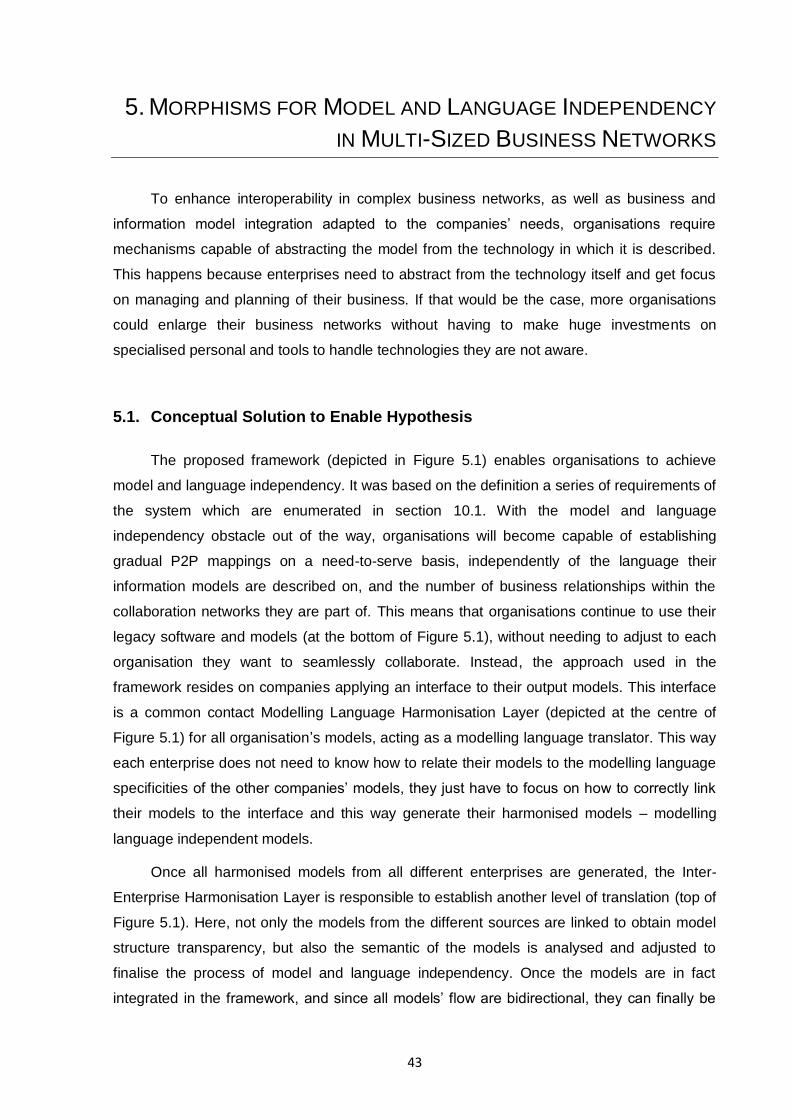
43
5. MORPHISMS FOR MODEL AND LANGUAGE INDEPENDENCY
IN MULTI-SIZED BUSINESS NETWORKS
To enhance interoperability in complex business networks, as well as business and
information model integration adapted to the companies‟ needs, organisations require
mechanisms capable of abstracting the model from the technology in which it is described.
This happens because enterprises need to abstract from the technology itself and get focus
on managing and planning of their business. If that would be the case, more organisations
could enlarge their business networks without having to make huge investments on
specialised personal and tools to handle technologies they are not aware.
5.1. Conceptual Solution to Enable Hypothesis
The proposed framework (depicted in Figure 5.1) enables organisations to achieve
model and language independency. It was based on the definition a series of requirements of
the system which are enumerated in section 10.1. With the model and language
independency obstacle out of the way, organisations will become capable of establishing
gradual P2P mappings on a need-to-serve basis, independently of the language their
information models are described on, and the number of business relationships within the
collaboration networks they are part of. This means that organisations continue to use their
legacy software and models (at the bottom of Figure 5.1), without needing to adjust to each
organisation they want to seamlessly collaborate. Instead, the approach used in the
framework resides on companies applying an interface to their output models. This interface
is a common contact Modelling Language Harmonisation Layer (depicted at the centre of
Figure 5.1) for all organisation‟s models, acting as a modelling language translator. This way
each enterprise does not need to know how to relate their models to the modelling language
specificities of the other companies‟ models, they just have to focus on how to correctly link
their models to the interface and this way generate their harmonised models – modelling
language independent models.
Once all harmonised models from all different enterprises are generated, the Inter-
Enterprise Harmonisation Layer is responsible to establish another level of translation (top of
Figure 5.1). Here, not only the models from the different sources are linked to obtain model
structure transparency, but also the semantic of the models is analysed and adjusted to
finalise the process of model and language independency. Once the models are in fact
integrated in the framework, and since all models‟ flow are bidirectional, they can finally be
44
exported back to any desired compatible source which is already connected to the
framework, allowing bidirectional communication of enterprises and achieving the desired
enterprises‟ transparency of technology envisaged.
Figure 5.1 – High level abstraction framework of the conceptual solution
The proposal depicted in Figure 5.1 is an interpretation and refinement of ISO/IEC
11179 Metadata Registries (MDR) [102]. ISO/IEC 11179 describes the standardising and
registering of data elements to make data understandable and shareable. Data element
standardisation and registration, as described in ISO/IEC 11179, allow the creation of a
shared data environment in much less time and with much less effort than it takes for
conventional data management methodologies, and it is applicable and not limited to:
Enabling global data acquisition and interchange, particularly across application
areas;
When documentation of data element characteristics is inadequate to support
fully automated sharing of data, including locating, retrieving, and exchanging
the data.
The refinement applied to ISO/IEC 11179 tried to simplify the enterprises‟ adoption
45
process and maintain the overall time and money spent as low as possible when compared
with the need for adopting a complex model and data representation standard such as ISO
10303 – STEP for exchanging information. On the other hand, since this conceptual
approach does not have a specific domain of action, it is possible to embrace several
domains (e.g. aeronautics, furniture, automotive, etc) with it, enabling different domain
enterprises to communicate and collaborate.
5.1.1. MDA-based Framework for Language Independency
In order to materialise the high level abstraction framework of the conceptual solution
(depicted on Figure 5.1), a more complete representation of the proposal is depicted on
Figure 5.2. It is based on a four level MDA applied structured relationships between meta-
meta-models, meta-models, information models and data.
The left (Enterprise A, with blue background) and right-hand (Enterprise B, green
background) sides of Figure 5.2 represent the two different organisations‟ internal legacy
models where the data is described by the respective model, which by itself is defined by its
meta-model which ultimately conforms to a meta-meta-model. The core of the framework is
represented by the middle part (Inter-Enterprise Harmonisation Layer, with grey
background), which includes the Common Base (sustained by the Central Meta-Model and
its instances, defined in section 5.2) and serves as a standard during the mapping
establishment (morphism) within the collaboration network. Analogous to Figure 5.1, in
Figure 5.2 are specified the abstraction layers of the earlier figure. The Modelling Language
Harmonisation Layer (responsible for modelling language translation) is represented by all
morphisms at the interfaces between the Enterprise A and B, and the framework‟s core. The
latter is in fact the Inter-Enterprise Harmonisation Layer itself, being responsible for the
model and semantics harmonisation.
Since the problematic is on achieving interoperability between same levels of
abstraction of the organisations involved, the framework makes use of horizontal morphisms
which can support the harmonisation of both models and data levels (Level 1 and 0,
respectively). These morphisms are the base for both Modelling Language Harmonisation
and Inter-Enterprise Harmonisation Layers, which are covered in detail on the next sections.
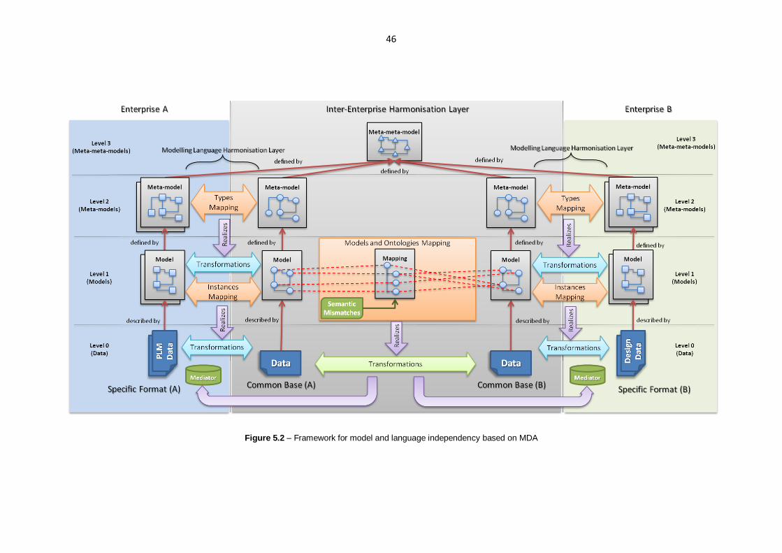
46
Figure 5.2 – Framework for model and language independency based on MDA
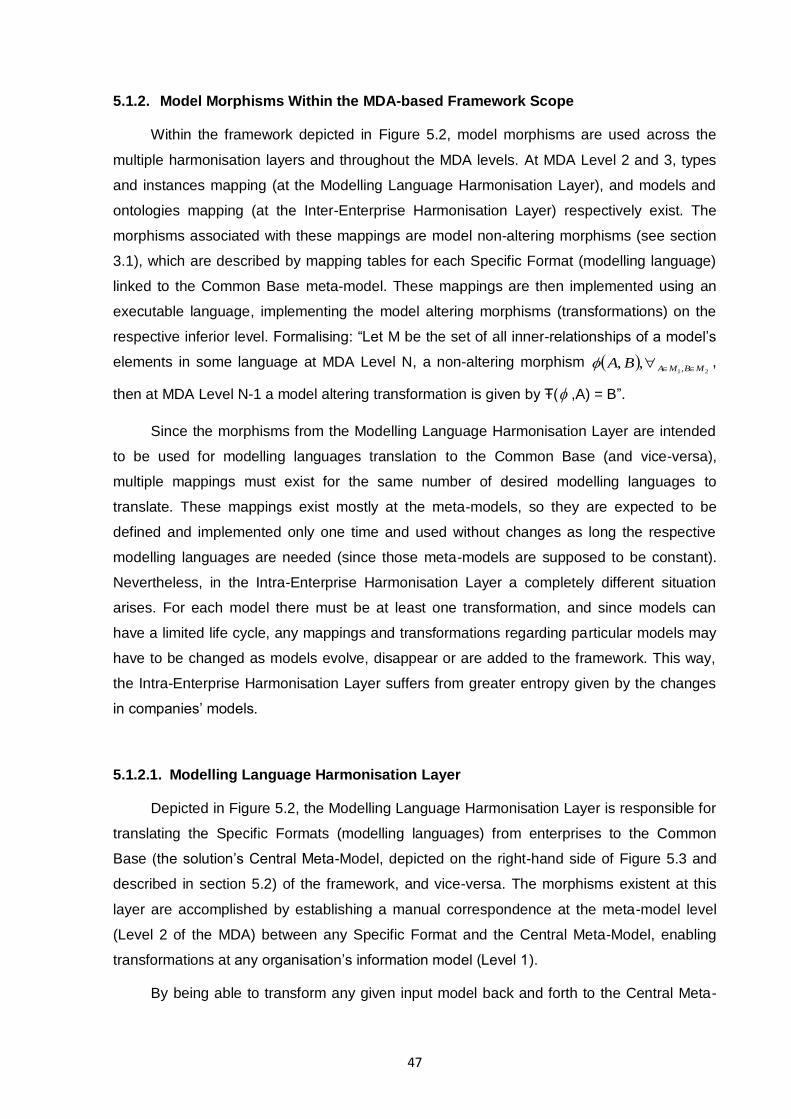
47
5.1.2. Model Morphisms Within the MDA-based Framework Scope
Within the framework depicted in Figure 5.2, model morphisms are used across the
multiple harmonisation layers and throughout the MDA levels. At MDA Level 2 and 3, types
and instances mapping (at the Modelling Language Harmonisation Layer), and models and
ontologies mapping (at the Inter-Enterprise Harmonisation Layer) respectively exist. The
morphisms associated with these mappings are model non-altering morphisms (see section
3.1), which are described by mapping tables for each Specific Format (modelling language)
linked to the Common Base meta-model. These mappings are then implemented using an
executable language, implementing the model altering morphisms (transformations) on the
respective inferior level. Formalising: “Let M be the set of all inner-relationships of a model‟s
elements in some language at MDA Level N, a non-altering morphism 21,,, MBMABA ,
then at MDA Level N-1 a model altering transformation is given by Ŧ( ,A) = B”.
Since the morphisms from the Modelling Language Harmonisation Layer are intended
to be used for modelling languages translation to the Common Base (and vice-versa),
multiple mappings must exist for the same number of desired modelling languages to
translate. These mappings exist mostly at the meta-models, so they are expected to be
defined and implemented only one time and used without changes as long the respective
modelling languages are needed (since those meta-models are supposed to be constant).
Nevertheless, in the Intra-Enterprise Harmonisation Layer a completely different situation
arises. For each model there must be at least one transformation, and since models can
have a limited life cycle, any mappings and transformations regarding particular models may
have to be changed as models evolve, disappear or are added to the framework. This way,
the Intra-Enterprise Harmonisation Layer suffers from greater entropy given by the changes
in companies‟ models.
5.1.2.1. Modelling Language Harmonisation Layer
Depicted in Figure 5.2, the Modelling Language Harmonisation Layer is responsible for
translating the Specific Formats (modelling languages) from enterprises to the Common
Base (the solution‟s Central Meta-Model, depicted on the right-hand side of Figure 5.3 and
described in section 5.2) of the framework, and vice-versa. The morphisms existent at this
layer are accomplished by establishing a manual correspondence at the meta-model level
(Level 2 of the MDA) between any Specific Format and the Central Meta-Model, enabling
transformations at any organisation‟s information model (Level 1).
By being able to transform any given input model back and forth to the Central Meta-
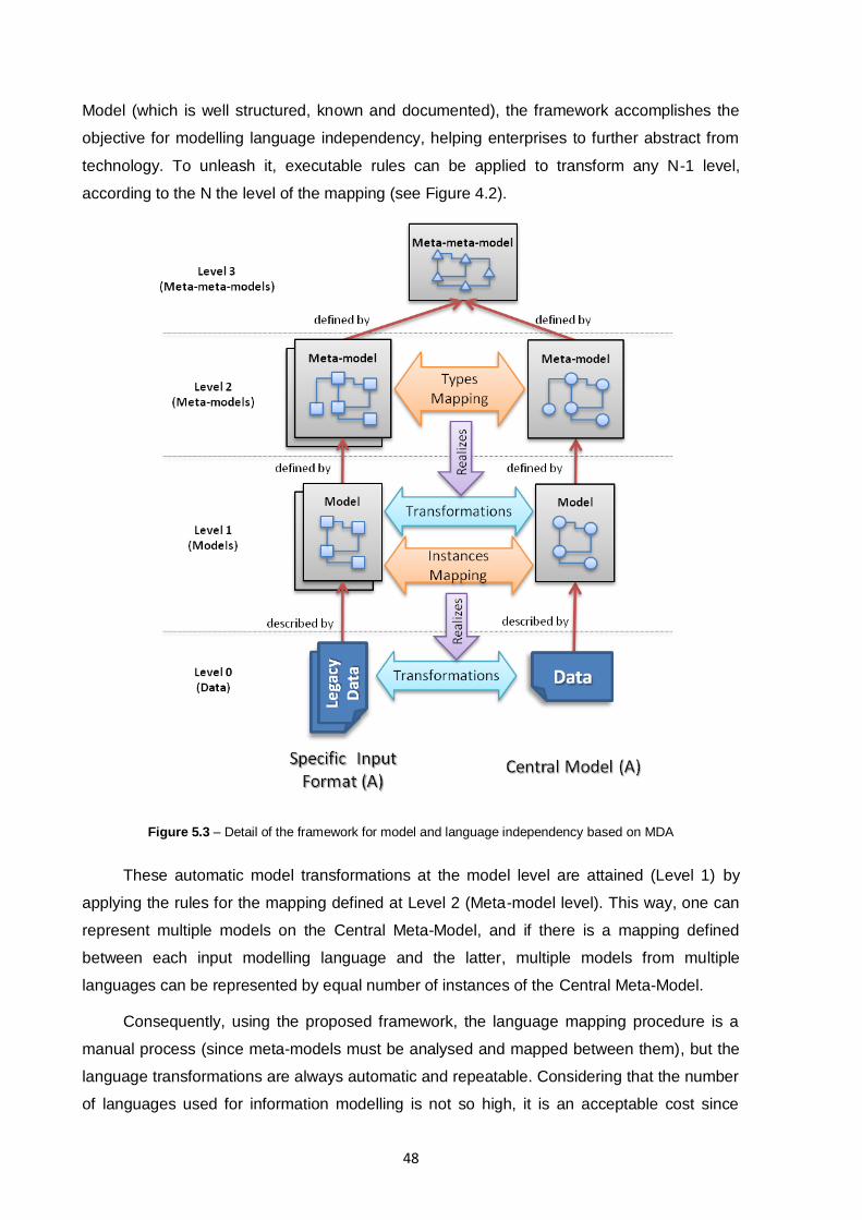
48
Model (which is well structured, known and documented), the framework accomplishes the
objective for modelling language independency, helping enterprises to further abstract from
technology. To unleash it, executable rules can be applied to transform any N-1 level,
according to the N the level of the mapping (see Figure 4.2).
Figure 5.3 – Detail of the framework for model and language independency based on MDA
These automatic model transformations at the model level are attained (Level 1) by
applying the rules for the mapping defined at Level 2 (Meta-model level). This way, one can
represent multiple models on the Central Meta-Model, and if there is a mapping defined
between each input modelling language and the latter, multiple models from multiple
languages can be represented by equal number of instances of the Central Meta-Model.
Consequently, using the proposed framework, the language mapping procedure is a
manual process (since meta-models must be analysed and mapped between them), but the
language transformations are always automatic and repeatable. Considering that the number
of languages used for information modelling is not so high, it is an acceptable cost since

49
each map is done only once for the whole collaboration life period, independently of the
number of times it is used / executed.
5.1.2.2. Inter-Enterprise Harmonisation Layer
Once all models from different enterprises and modelling languages are harmonised to
a central and common language and meta-model (Central Meta-Model), another very
important problematic of collaboration can be addressed: the semantic mismatches of the
various models from the organisations and their correct model integration. The framework
takes this in account by allowing model and ontologies mapping at the models level (Level 1)
and between Central Meta-Model instances. This way, the mappings realised at this point
don‟t suffer from the extra complexity of dealing with multi-modelling languages, easing the
process of harmonising the semantic and structure level of models and ontologies. At the
centre of Figure 5.2 is depicted this interaction between models and ontologies mapping with
the semantic mismatches evaluation.
The result of the process of evaluating semantic mismatches and models mapping is
the seamless generation of transformations (at the bottom centre of Figure 5.2, in green)
between models and data from Enterprise A to Enterprise B and vice-versa. By its turn, each
pair of transformation is then stored on knowledge-bases (Knowledge-Base Mediator – see
section 5.3) on each of the organisations side, which will allow exchanging data and models
automatically (by means of transformations executions) in a P2P approach.
Since these transformations (at the bottom centre of Figure 5.2, in green) only apply to
the inner concepts (structural and semantic) of the Central Meta-Model instances, also the
Modelling Language Harmonisation Layer transformations (right and left-hand of Figure 5.2,
in blue) must be stored on each Mediator, regarding how to transform the Specific Models of
each organisation from and to the Central Meta-Model. This way, the union of the two
transformations (for each direction of communication) unleashes the capability of both
automatic and transparently communicate and collaborate with other organisations, with
different modelling languages, models, semantics and ontologies. On the other hand, by
storing these transformations, future changes on models and meta-models can be reflected
on the previous transformations. Finally, also traceability and repeatability are inherently
available by storing the transformations in the knowledge-bases.
Although this conceptual framework proposes a complete solution to enable the model
and language independency in multi-sized business networks, it is more focused in enabling
the harmonisation of the heterogeneous models from the multiple organisations involved in
the collaboration network. These models then act as inputs for the semantics analysis and it
50
is not in the scope of this dissertation the further refinement of how models and ontologies
are mapped accordingly with the semantic mismatches, and how the transformations occur
within the harmonised upper layer (Inter-Enterprise Harmonisation Layer, in gray
background).
Other works have been developed in parallel to this dissertation, which evolved and
cooperated to the maturation of the presented framework. This way, they cover both how the
semantic mismatches are identified and applied to the mapping between each pair of
harmonised models from the organisations involved, and also how Level 0 transformations
(at the bottom centre of Figure 5.2, in green) between the Central Meta-Model instances are
generated, stored, accessed and executed in combination with the modelling language
harmonising transformations (right and left-hand of Figure 5.2, in blue). With this, the sum of
all three research works explains and covers in detail the entire framework‟s inwards and
proof-of-concept.
As been said before, the process of mapping between different information model
structures at the Central Meta-Model instances (i.e. Level 1) is not part of this dissertation.
However, with such a framework, the complete automatic data exchange and translation can
be accomplished between different model instances at the Level 0, thus completing the base
for sustainable systems interoperability. Since all mappings of Level 1 can be stored on a
local knowledge base, it enables to gradually add more mappings with other enterprises and
even to edit or delete past mappings. This provides the required adaptability of the
framework to small collaboration networks, and being able to escalate to larger scenarios. A
usage scenario explaining the complete picture is included in section 5.4.
5.2. The Central Meta-Model
The Central Meta-Model proposed is described as an UML class diagram meta-model
in Figure 5.4. It was designed with an UML design tool, since UML class diagrams are a
good starting point for visualising the meta-model, plus it is possible to be exported as a
lossless MOF XMI model. It was intended to be as little loss of expressiveness as possible,
but at the same time simple and generic to support multiple language mappings. The
resembles with ISO/IEC 11179 standard are not by fortuity, since the Central Meta-Model
was based on the standard foundations and concepts in order to give support to mechanisms
for enabling global data interchange, particularly across application areas [102]. A bridge
between major concepts of the Central Meta-Model and ISO/IEC 11179 can be made, such
as “Entity”, “Property” and “Representation” concepts in the standard corresponds to
“Entity_Concept”, “Property” and “Representation” concepts of the Central Meta-Model.
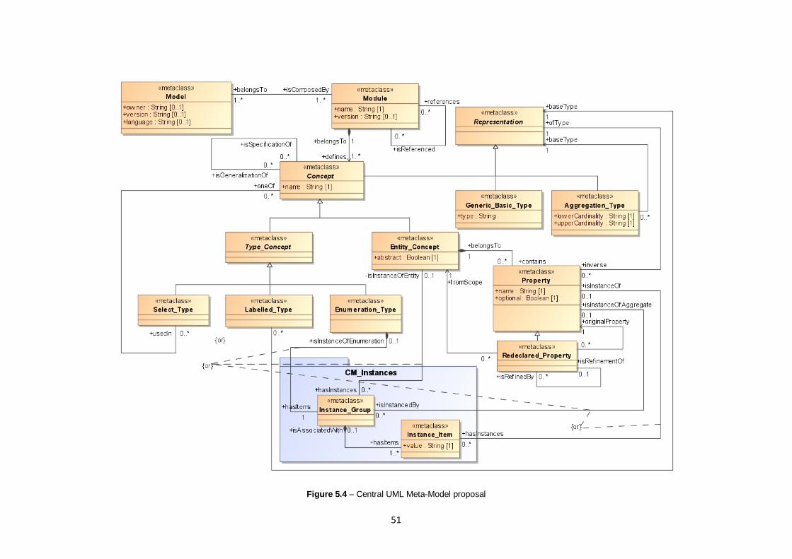
51
Figure 5.4 – Central UML Meta-Model proposal
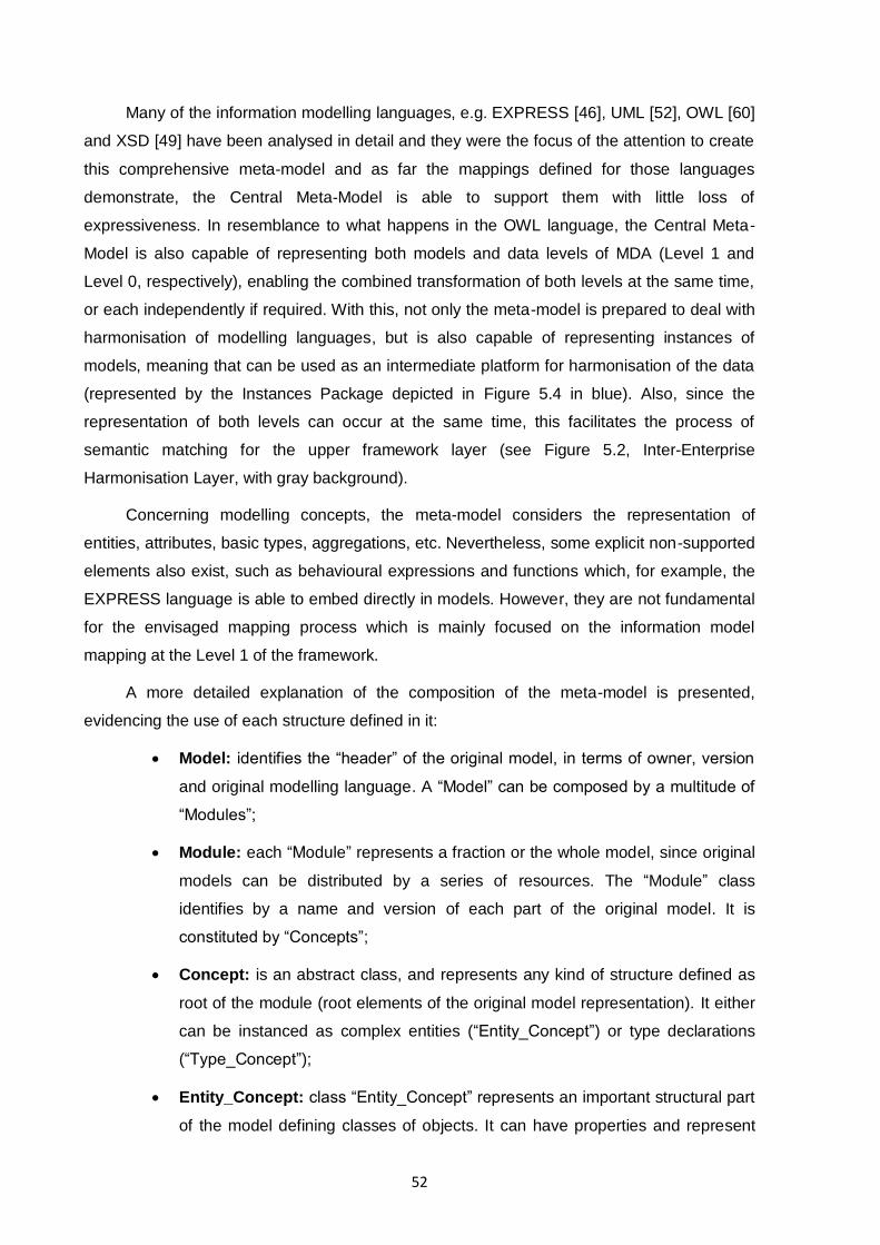
52
Many of the information modelling languages, e.g. EXPRESS [46], UML [52], OWL [60]
and XSD [49] have been analysed in detail and they were the focus of the attention to create
this comprehensive meta-model and as far the mappings defined for those languages
demonstrate, the Central Meta-Model is able to support them with little loss of
expressiveness. In resemblance to what happens in the OWL language, the Central Meta-
Model is also capable of representing both models and data levels of MDA (Level 1 and
Level 0, respectively), enabling the combined transformation of both levels at the same time,
or each independently if required. With this, not only the meta-model is prepared to deal with
harmonisation of modelling languages, but is also capable of representing instances of
models, meaning that can be used as an intermediate platform for harmonisation of the data
(represented by the Instances Package depicted in Figure 5.4 in blue). Also, since the
representation of both levels can occur at the same time, this facilitates the process of
semantic matching for the upper framework layer (see Figure 5.2, Inter-Enterprise
Harmonisation Layer, with gray background).
Concerning modelling concepts, the meta-model considers the representation of
entities, attributes, basic types, aggregations, etc. Nevertheless, some explicit non-supported
elements also exist, such as behavioural expressions and functions which, for example, the
EXPRESS language is able to embed directly in models. However, they are not fundamental
for the envisaged mapping process which is mainly focused on the information model
mapping at the Level 1 of the framework.
A more detailed explanation of the composition of the meta-model is presented,
evidencing the use of each structure defined in it:
Model: identifies the “header” of the original model, in terms of owner, version
and original modelling language. A “Model” can be composed by a multitude of
“Modules”;
Module: each “Module” represents a fraction or the whole model, since original
models can be distributed by a series of resources. The “Module” class
identifies by a name and version of each part of the original model. It is
constituted by “Concepts”;
Concept: is an abstract class, and represents any kind of structure defined as
root of the module (root elements of the original model representation). It either
can be instanced as complex entities (“Entity_Concept”) or type declarations
(“Type_Concept”);
Entity_Concept: class “Entity_Concept” represents an important structural part
of the model defining classes of objects. It can have properties and represent
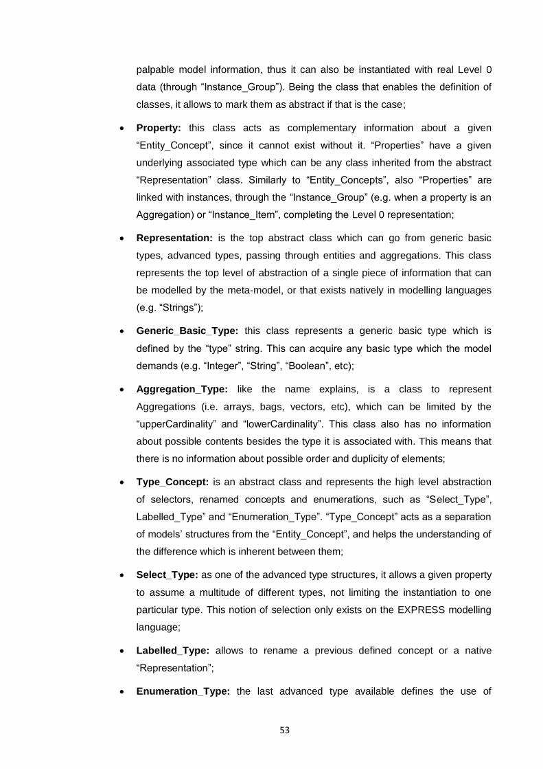
53
palpable model information, thus it can also be instantiated with real Level 0
data (through “Instance_Group”). Being the class that enables the definition of
classes, it allows to mark them as abstract if that is the case;
Property: this class acts as complementary information about a given
“Entity_Concept”, since it cannot exist without it. “Properties” have a given
underlying associated type which can be any class inherited from the abstract
“Representation” class. Similarly to “Entity_Concepts”, also “Properties” are
linked with instances, through the “Instance_Group” (e.g. when a property is an
Aggregation) or “Instance_Item”, completing the Level 0 representation;
Representation: is the top abstract class which can go from generic basic
types, advanced types, passing through entities and aggregations. This class
represents the top level of abstraction of a single piece of information that can
be modelled by the meta-model, or that exists natively in modelling languages
(e.g. “Strings”);
Generic_Basic_Type: this class represents a generic basic type which is
defined by the “type” string. This can acquire any basic type which the model
demands (e.g. “Integer”, “String”, “Boolean”, etc);
Aggregation_Type: like the name explains, is a class to represent
Aggregations (i.e. arrays, bags, vectors, etc), which can be limited by the
“upperCardinality” and “lowerCardinality”. This class also has no information
about possible contents besides the type it is associated with. This means that
there is no information about possible order and duplicity of elements;
Type_Concept: is an abstract class and represents the high level abstraction
of selectors, renamed concepts and enumerations, such as “Select_Type”,
Labelled_Type” and “Enumeration_Type”. “Type_Concept” acts as a separation
of models‟ structures from the “Entity_Concept”, and helps the understanding of
the difference which is inherent between them;
Select_Type: as one of the advanced type structures, it allows a given property
to assume a multitude of different types, not limiting the instantiation to one
particular type. This notion of selection only exists on the EXPRESS modelling
language;
Labelled_Type: allows to rename a previous defined concept or a native
“Representation”;
Enumeration_Type: the last advanced type available defines the use of
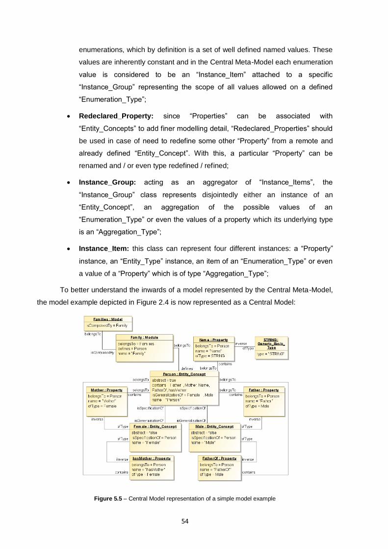
54
enumerations, which by definition is a set of well defined named values. These
values are inherently constant and in the Central Meta-Model each enumeration
value is considered to be an “Instance_Item” attached to a specific
“Instance_Group” representing the scope of all values allowed on a defined
“Enumeration_Type”;
Redeclared_Property: since “Properties” can be associated with
“Entity_Concepts” to add finer modelling detail, “Redeclared_Properties” should
be used in case of need to redefine some other “Property” from a remote and
already defined “Entity_Concept”. With this, a particular “Property” can be
renamed and / or even type redefined / refined;
Instance_Group: acting as an aggregator of “Instance_Items”, the
“Instance_Group” class represents disjointedly either an instance of an
“Entity_Concept”, an aggregation of the possible values of an
“Enumeration_Type” or even the values of a property which its underlying type
is an “Aggregation_Type”;
Instance_Item: this class can represent four different instances: a “Property”
instance, an “Entity_Type” instance, an item of an “Enumeration_Type” or even
a value of a “Property” which is of type “Aggregation_Type”;
To better understand the inwards of a model represented by the Central Meta-Model,
the model example depicted in Figure 2.4 is now represented as a Central Model:
Figure 5.5 – Central Model representation of a simple model example
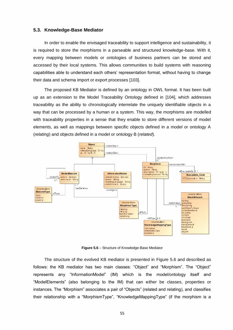
55
5.3. Knowledge-Base Mediator
In order to enable the envisaged traceability to support intelligence and sustainability, it
is required to store the morphisms in a parseable and structured knowledge-base. With it,
every mapping between models or ontologies of business partners can be stored and
accessed by their local systems. This allows communities to build systems with reasoning
capabilities able to understand each others‟ representation format, without having to change
their data and schema import or export processes [103].
The proposed KB Mediator is defined by an ontology in OWL format. It has been built
up as an extension to the Model Traceability Ontology defined in [104], which addresses
traceability as the ability to chronologically interrelate the uniquely identifiable objects in a
way that can be processed by a human or a system. This way, the morphisms are modelled
with traceability properties in a sense that they enable to store different versions of model
elements, as well as mappings between specific objects defined in a model or ontology A
(relating) and objects defined in a model or ontology B (related).
Figure 5.6 – Structure of Knowledge-Base Mediator
The structure of the evolved KB mediator is presented in Figure 5.6 and described as
follows: the KB mediator has two main classes: “Object” and “Morphism”. The “Object”
represents any “InformationModel” (IM) which is the model/ontology itself and
“ModelElements” (also belonging to the IM) that can either be classes, properties or
instances. The “Morphism” associates a pair of “Objects” (related and relating), and classifies
their relationship with a “MorphismType”, “KnowledgeMappingType” (if the morphism is a
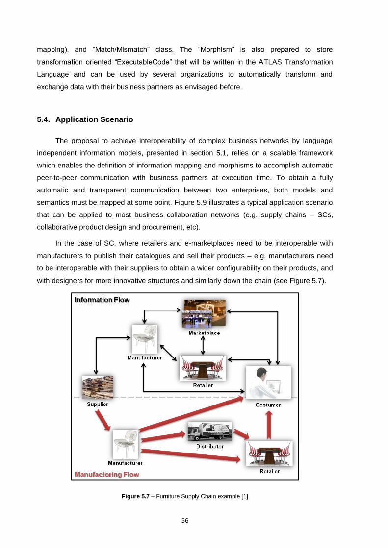
56
mapping), and “Match/Mismatch” class. The “Morphism” is also prepared to store
transformation oriented “ExecutableCode” that will be written in the ATLAS Transformation
Language and can be used by several organizations to automatically transform and
exchange data with their business partners as envisaged before.
5.4. Application Scenario
The proposal to achieve interoperability of complex business networks by language
independent information models, presented in section 5.1, relies on a scalable framework
which enables the definition of information mapping and morphisms to accomplish automatic
peer-to-peer communication with business partners at execution time. To obtain a fully
automatic and transparent communication between two enterprises, both models and
semantics must be mapped at some point. Figure 5.9 illustrates a typical application scenario
that can be applied to most business collaboration networks (e.g. supply chains – SCs,
collaborative product design and procurement, etc).
In the case of SC, where retailers and e-marketplaces need to be interoperable with
manufacturers to publish their catalogues and sell their products – e.g. manufacturers need
to be interoperable with their suppliers to obtain a wider configurability on their products, and
with designers for more innovative structures and similarly down the chain (see Figure 5.7).
Figure 5.7 – Furniture Supply Chain example [1]
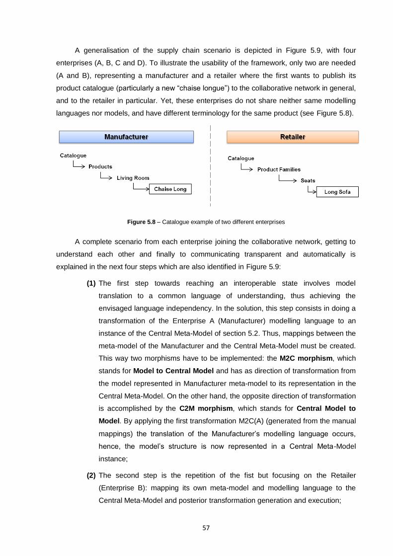
57
A generalisation of the supply chain scenario is depicted in Figure 5.9, with four
enterprises (A, B, C and D). To illustrate the usability of the framework, only two are needed
(A and B), representing a manufacturer and a retailer where the first wants to publish its
product catalogue (particularly a new “chaise longue”) to the collaborative network in general,
and to the retailer in particular. Yet, these enterprises do not share neither same modelling
languages nor models, and have different terminology for the same product (see Figure 5.8).
Figure 5.8 – Catalogue example of two different enterprises
A complete scenario from each enterprise joining the collaborative network, getting to
understand each other and finally to communicating transparent and automatically is
explained in the next four steps which are also identified in Figure 5.9:
(1) The first step towards reaching an interoperable state involves model
translation to a common language of understanding, thus achieving the
envisaged language independency. In the solution, this step consists in doing a
transformation of the Enterprise A (Manufacturer) modelling language to an
instance of the Central Meta-Model of section 5.2. Thus, mappings between the
meta-model of the Manufacturer and the Central Meta-Model must be created.
This way two morphisms have to be implemented: the M2C morphism, which
stands for Model to Central Model and has as direction of transformation from
the model represented in Manufacturer meta-model to its representation in the
Central Meta-Model. On the other hand, the opposite direction of transformation
is accomplished by the C2M morphism, which stands for Central Model to
Model. By applying the first transformation M2C(A) (generated from the manual
mappings) the translation of the Manufacturer‟s modelling language occurs,
hence, the model‟s structure is now represented in a Central Meta-Model
instance;
(2) The second step is the repetition of the fist but focusing on the Retailer
(Enterprise B): mapping its own meta-model and modelling language to the
Central Meta-Model and posterior transformation generation and execution;
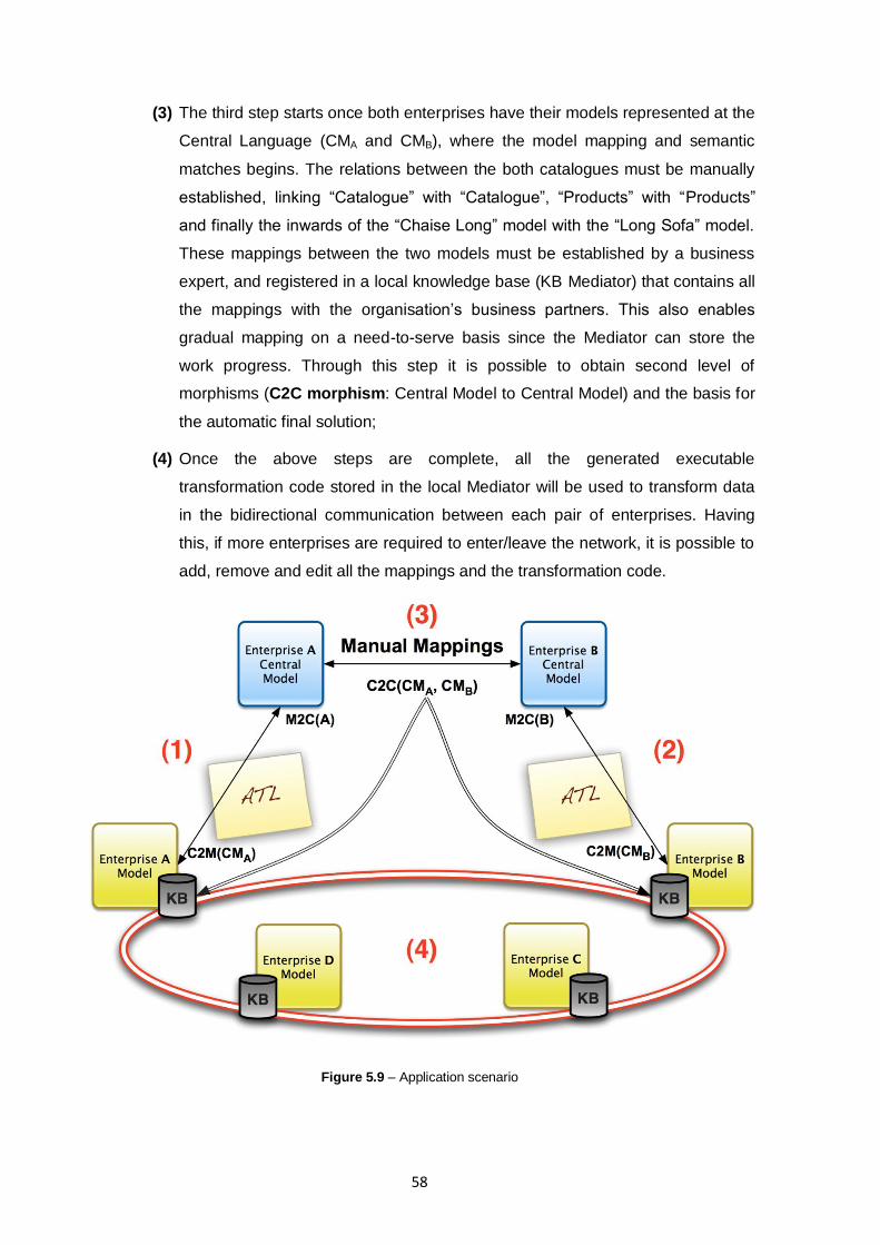
58
(3) The third step starts once both enterprises have their models represented at the
Central Language (CMA and CMB), where the model mapping and semantic
matches begins. The relations between the both catalogues must be manually
established, linking “Catalogue” with “Catalogue”, “Products” with “Products”
and finally the inwards of the “Chaise Long” model with the “Long Sofa” model.
These mappings between the two models must be established by a business
expert, and registered in a local knowledge base (KB Mediator) that contains all
the mappings with the organisation‟s business partners. This also enables
gradual mapping on a need-to-serve basis since the Mediator can store the
work progress. Through this step it is possible to obtain second level of
morphisms (C2C morphism: Central Model to Central Model) and the basis for
the automatic final solution;
(4) Once the above steps are complete, all the generated executable
transformation code stored in the local Mediator will be used to transform data
in the bidirectional communication between each pair of enterprises. Having
this, if more enterprises are required to enter/leave the network, it is possible to
add, remove and edit all the mappings and the transformation code.
Figure 5.9 – Application scenario
59
6. PROOF-OF-CONCEPT IMPLEMENTATION
In order to validate the viability of the framework proposed in section 5.1, it was
necessary to implement a part of it. Since this dissertation has a main focus over the
Modelling Language Harmonisation Layer (see Figure 5.1), it was also chosen to be the
proof-of-concept implementation focus. On the other hand, this dissertation was developed
aggregated with Group for Research in Interoperability of Systems (GRIS) at UNINOVA,
which already have many research works related with the integration of STEP technologies
with others more open and popular among developers [1] [7] [58] [59] [66] [103] [104],
EXPRESS was the elected modelling language to prove the concept, thus not only map to
the Central Meta-Model but also to implement the proof-of-concept morphisms. All the
EXPRESS expertise which was available as human knowledge and the possible positive
results of this implementation were also aspects for its choice, and to further develop MDA-
based tools to its manipulation.
In this case, the proof-of-concept implementation consists in the bottom up
development of the framework but not concerning with the Inter-Enterprise Harmonisation
Layer. This means that the software layer developed resolves the translation from the
EXPRESS modelling language to the Central Model and vice-versa, delivering its results to
the Inter-Enterprise Harmonisation Layer which will resolve the semantic and model
integration of the harmonised models.
Although this proof-of-concept is limited to the EXPRESS modelling language, others
(such as UML, OWL and XML Schema) were considered on the development of the
framework (depicted in Figure 5.2). From these, XML Schema modelling language, similarly
as EXPRESS, was mapped to the Central Meta-Model (see section 10.2.2).
6.1. Implementation Overview and Technology Used
As seen before on section 2.4.2, EXPRESS modelling language models can be
represented as either in the text (EXPRESS) or graphical (EXPRESS-G) formats, being the
text format the most complete representation due to the loss of expressiveness of EXPRESS
expressions inherent to the graphical format. On the other hand, ISO 10303-21 (STEP Part
21) is the most used data format exchanged between EXPRESS enabled systems. This
format enables the representation of models‟ data without exchanging the whole original
models, reducing the amount of real data exchanged between the systems. Nevertheless,
this compels to a prior communication to synchronise (wireless or not) complete models and
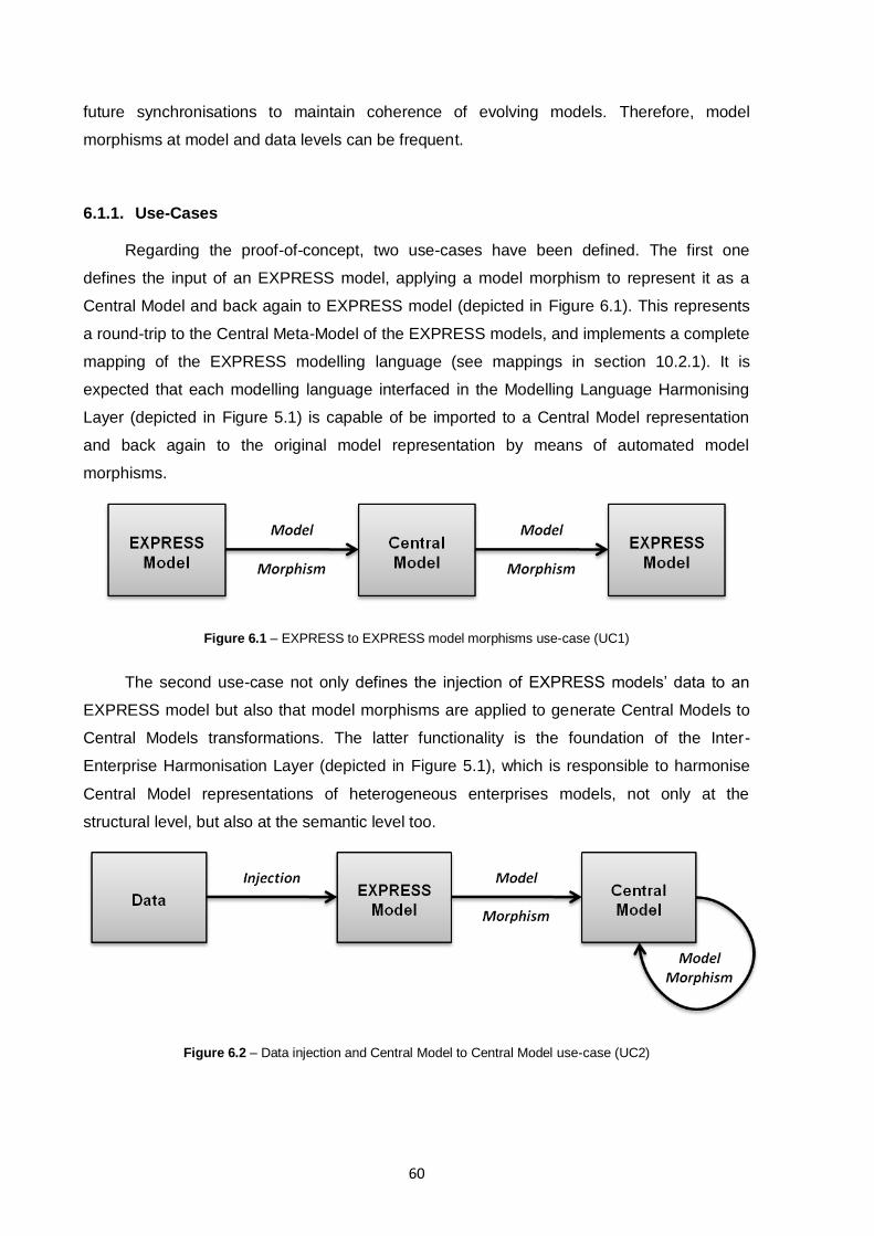
60
future synchronisations to maintain coherence of evolving models. Therefore, model
morphisms at model and data levels can be frequent.
6.1.1. Use-Cases
Regarding the proof-of-concept, two use-cases have been defined. The first one
defines the input of an EXPRESS model, applying a model morphism to represent it as a
Central Model and back again to EXPRESS model (depicted in Figure 6.1). This represents
a round-trip to the Central Meta-Model of the EXPRESS models, and implements a complete
mapping of the EXPRESS modelling language (see mappings in section 10.2.1). It is
expected that each modelling language interfaced in the Modelling Language Harmonising
Layer (depicted in Figure 5.1) is capable of be imported to a Central Model representation
and back again to the original model representation by means of automated model
morphisms.
Figure 6.1 – EXPRESS to EXPRESS model morphisms use-case (UC1)
The second use-case not only defines the injection of EXPRESS models‟ data to an
EXPRESS model but also that model morphisms are applied to generate Central Models to
Central Models transformations. The latter functionality is the foundation of the Inter-
Enterprise Harmonisation Layer (depicted in Figure 5.1), which is responsible to harmonise
Central Model representations of heterogeneous enterprises models, not only at the
structural level, but also at the semantic level too.
Figure 6.2 – Data injection and Central Model to Central Model use-case (UC2)
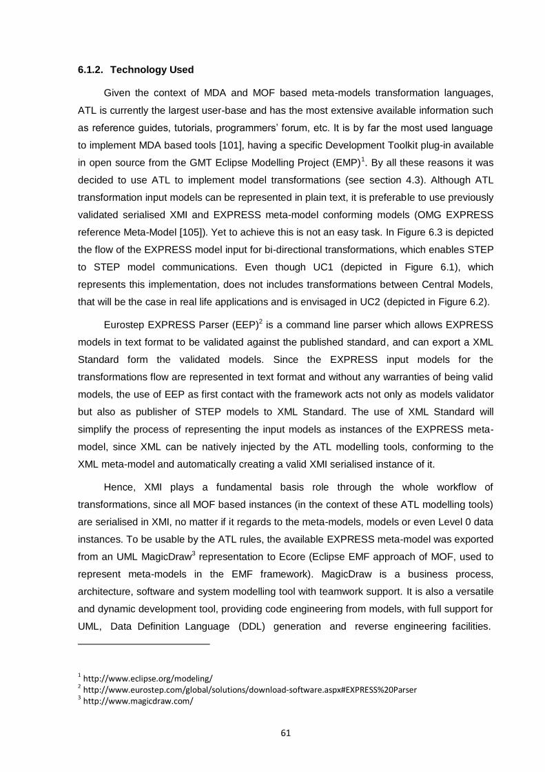
61
6.1.2. Technology Used
Given the context of MDA and MOF based meta-models transformation languages,
ATL is currently the largest user-base and has the most extensive available information such
as reference guides, tutorials, programmers‟ forum, etc. It is by far the most used language
to implement MDA based tools [101], having a specific Development Toolkit plug-in available
in open source from the GMT Eclipse Modelling Project (EMP)1. By all these reasons it was
decided to use ATL to implement model transformations (see section 4.3). Although ATL
transformation input models can be represented in plain text, it is preferable to use previously
validated serialised XMI and EXPRESS meta-model conforming models (OMG EXPRESS
reference Meta-Model [105]). Yet to achieve this is not an easy task. In Figure 6.3 is depicted
the flow of the EXPRESS model input for bi-directional transformations, which enables STEP
to STEP model communications. Even though UC1 (depicted in Figure 6.1), which
represents this implementation, does not includes transformations between Central Models,
that will be the case in real life applications and is envisaged in UC2 (depicted in Figure 6.2).
Eurostep EXPRESS Parser (EEP)2 is a command line parser which allows EXPRESS
models in text format to be validated against the published standard, and can export a XML
Standard form the validated models. Since the EXPRESS input models for the
transformations flow are represented in text format and without any warranties of being valid
models, the use of EEP as first contact with the framework acts not only as models validator
but also as publisher of STEP models to XML Standard. The use of XML Standard will
simplify the process of representing the input models as instances of the EXPRESS meta-
model, since XML can be natively injected by the ATL modelling tools, conforming to the
XML meta-model and automatically creating a valid XMI serialised instance of it.
Hence, XMI plays a fundamental basis role through the whole workflow of
transformations, since all MOF based instances (in the context of these ATL modelling tools)
are serialised in XMI, no matter if it regards to the meta-models, models or even Level 0 data
instances. To be usable by the ATL rules, the available EXPRESS meta-model was exported
from an UML MagicDraw3 representation to Ecore (Eclipse EMF approach of MOF, used to
represent meta-models in the EMF framework). MagicDraw is a business process,
architecture, software and system modelling tool with teamwork support. It is also a versatile
and dynamic development tool, providing code engineering from models, with full support for
UML, Data Definition Language (DDL) generation and reverse engineering facilities.
1 http://www.eclipse.org/modeling/ 2 http://www.eurostep.com/global/solutions/download-software.aspx#EXPRESS%20Parser
3 http://www.magicdraw.com/
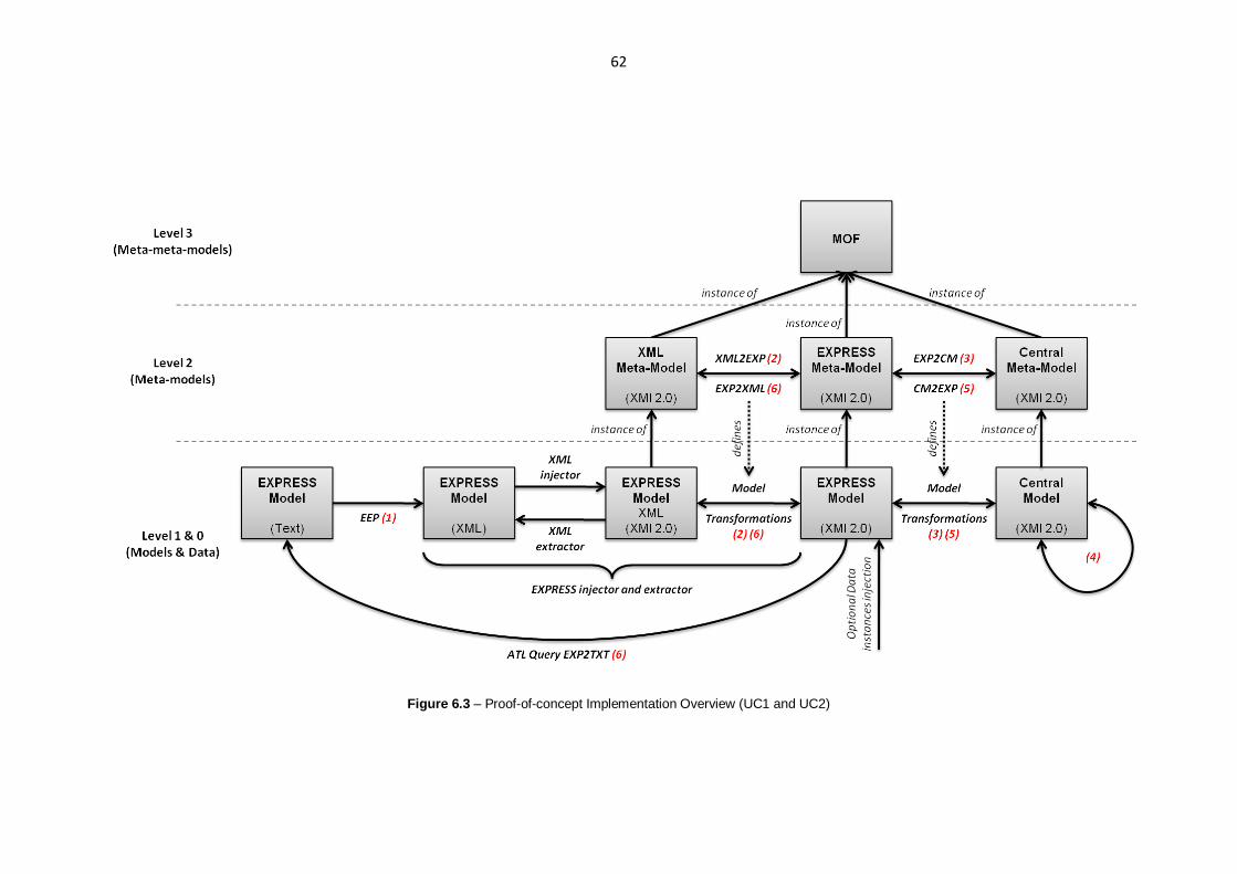
62
Figure 6.3 – Proof-of-concept Implementation Overview (UC1 and UC2)

63
MagicDraw (and in principle most UML tools) can export UML projects to a variety of other
formats / serialisations such as UML XMI 2.1, EMF Ecore, EMF UML2 v2.x and v1.x XMI,
MOF XMI and Business Process Execution Language (BPEL).
To summarise the most important technologies and tools used throughout the proof-of-
concept implementation, a short but objective purpose of those is presented in the next table.
Technology Tools
Purpose
Purpose
MDA Foundation for models’
transformations EEP
Validator and parser of text EXPRESS models to XML
ATL Executable transformation
language for model morphisms MagicDraw
UML designing tool for UML class diagrams definition and export to
Ecore XMI
MOF Basic constructs for model
representation
Ecore Approach of MOF implementation
by Eclipse EMF
XMI Format for models and data
interchangeable representation
Table 6.1 – Purpose of the used technologies and tools by the proof-of-concept implementation
6.2. Implementation Steps
The main objective of this proof-of-concept consists on the implementation of the
Modelling Language Harmonisation Layer (depicted in Figure 5.1) which implements
transformations responsible for inputting an EXPRESS model formatted as text (lower-left
corner of Figure 6.3), forward transforming it to a Central Meta-Model representation (steps 1
to 3 of Figure 6.3), delivering the results for the upper framework layer (Inter-Enterprise
Harmonisation Layer, for evaluation of semantic mismatches and model mappings, between
step 3 and 5), and backward transforming it to either EXPRESS text or XML representation
(steps 5 and 6).
Focusing only in the EXPRESS models as lower inputs and outputs of the Modelling
Language Harmonisation Layer, Figure 6.3 depicts all the transformations and validations
necessary to start with an EXPRESS model in text format, harmonise the model for the Inter-
Enterprise Harmonisation Layer usage (UC1), and finally transform it back to EXPRESS
either text or XML formatted. On the other hand, with step 3 and 4 is possible to inject Data
instances on an EXPRESS model, transform it to a Central Model and apply a structural
transformation to obtain another Central Model (UC2). In the next sections a thorough
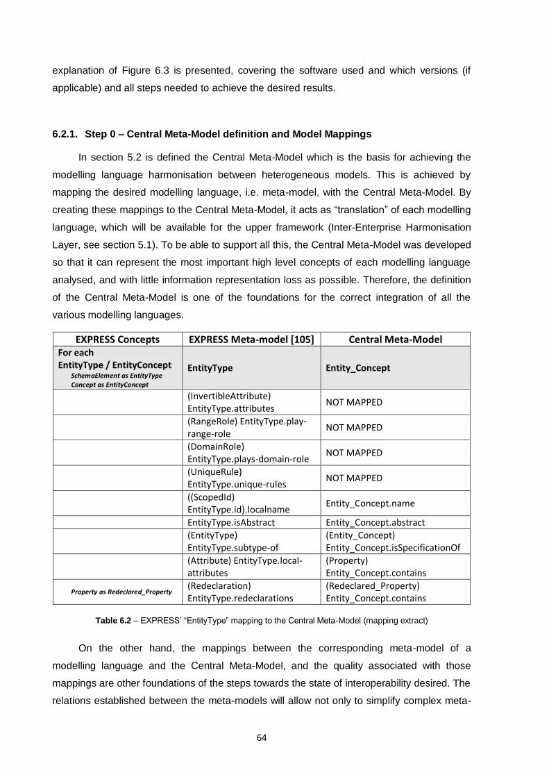
64
explanation of Figure 6.3 is presented, covering the software used and which versions (if
applicable) and all steps needed to achieve the desired results.
6.2.1. Step 0 – Central Meta-Model definition and Model Mappings
In section 5.2 is defined the Central Meta-Model which is the basis for achieving the
modelling language harmonisation between heterogeneous models. This is achieved by
mapping the desired modelling language, i.e. meta-model, with the Central Meta-Model. By
creating these mappings to the Central Meta-Model, it acts as “translation” of each modelling
language, which will be available for the upper framework (Inter-Enterprise Harmonisation
Layer, see section 5.1). To be able to support all this, the Central Meta-Model was developed
so that it can represent the most important high level concepts of each modelling language
analysed, and with little information representation loss as possible. Therefore, the definition
of the Central Meta-Model is one of the foundations for the correct integration of all the
various modelling languages.
EXPRESS Concepts EXPRESS Meta-model [105] Central Meta-Model For each EntityType / EntityConcept
SchemaElement as EntityType Concept as EntityConcept
EntityType Entity_Concept
(InvertibleAttribute) EntityType.attributes
NOT MAPPED
(RangeRole) EntityType.play-range-role
NOT MAPPED
(DomainRole) EntityType.plays-domain-role
NOT MAPPED
(UniqueRule) EntityType.unique-rules
NOT MAPPED
((ScopedId) EntityType.id).localname
Entity_Concept.name
EntityType.isAbstract Entity_Concept.abstract
(EntityType) EntityType.subtype-of
(Entity_Concept) Entity_Concept.isSpecificationOf
(Attribute) EntityType.local-attributes
(Property) Entity_Concept.contains
Property as Redeclared_Property (Redeclaration) EntityType.redeclarations
(Redeclared_Property) Entity_Concept.contains
Table 6.2 – EXPRESS‟ “EntityType” mapping to the Central Meta-Model (mapping extract)
On the other hand, the mappings between the corresponding meta-model of a
modelling language and the Central Meta-Model, and the quality associated with those
mappings are other foundations of the steps towards the state of interoperability desired. The
relations established between the meta-models will allow not only to simplify complex meta-
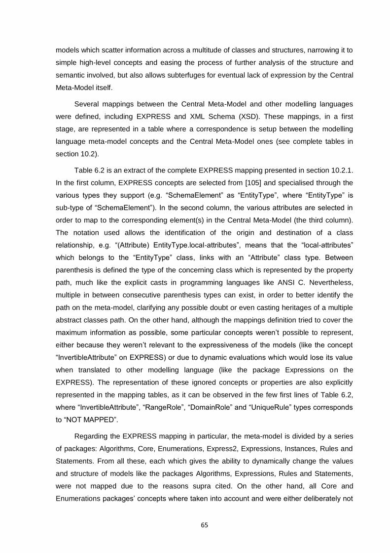
65
models which scatter information across a multitude of classes and structures, narrowing it to
simple high-level concepts and easing the process of further analysis of the structure and
semantic involved, but also allows subterfuges for eventual lack of expression by the Central
Meta-Model itself.
Several mappings between the Central Meta-Model and other modelling languages
were defined, including EXPRESS and XML Schema (XSD). These mappings, in a first
stage, are represented in a table where a correspondence is setup between the modelling
language meta-model concepts and the Central Meta-Model ones (see complete tables in
section 10.2).
Table 6.2 is an extract of the complete EXPRESS mapping presented in section 10.2.1.
In the first column, EXPRESS concepts are selected from [105] and specialised through the
various types they support (e.g. “SchemaElement” as “EntityType”, where “EntityType” is
sub-type of “SchemaElement”). In the second column, the various attributes are selected in
order to map to the corresponding element(s) in the Central Meta-Model (the third column).
The notation used allows the identification of the origin and destination of a class
relationship, e.g. “(Attribute) EntityType.local-attributes”, means that the “local-attributes”
which belongs to the “EntityType” class, links with an “Attribute” class type. Between
parenthesis is defined the type of the concerning class which is represented by the property
path, much like the explicit casts in programming languages like ANSI C. Nevertheless,
multiple in between consecutive parenthesis types can exist, in order to better identify the
path on the meta-model, clarifying any possible doubt or even casting heritages of a multiple
abstract classes path. On the other hand, although the mappings definition tried to cover the
maximum information as possible, some particular concepts weren‟t possible to represent,
either because they weren‟t relevant to the expressiveness of the models (like the concept
“InvertibleAttribute” on EXPRESS) or due to dynamic evaluations which would lose its value
when translated to other modelling language (like the package Expressions on the
EXPRESS). The representation of these ignored concepts or properties are also explicitly
represented in the mapping tables, as it can be observed in the few first lines of Table 6.2,
where “InvertibleAttribute”, “RangeRole”, “DomainRole” and “UniqueRule” types corresponds
to “NOT MAPPED”.
Regarding the EXPRESS mapping in particular, the meta-model is divided by a series
of packages: Algorithms, Core, Enumerations, Express2, Expressions, Instances, Rules and
Statements. From all these, each which gives the ability to dynamically change the values
and structure of models like the packages Algorithms, Expressions, Rules and Statements,
were not mapped due to the reasons supra cited. On the other hand, all Core and
Enumerations packages‟ concepts where taken into account and were either deliberately not
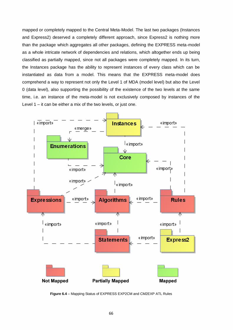
66
mapped or completely mapped to the Central Meta-Model. The last two packages (Instances
and Express2) deserved a completely different approach, since Express2 is nothing more
than the package which aggregates all other packages, defining the EXPRESS meta-model
as a whole intricate network of dependencies and relations, which altogether ends up being
classified as partially mapped, since not all packages were completely mapped. In its turn,
the Instances package has the ability to represent instances of every class which can be
instantiated as data from a model. This means that the EXPRESS meta-model does
comprehend a way to represent not only the Level 1 of MDA (model level) but also the Level
0 (data level), also supporting the possibility of the existence of the two levels at the same
time, i.e. an instance of the meta-model is not exclusively composed by instances of the
Level 1 – it can be either a mix of the two levels, or just one.
Figure 6.4 – Mapping Status of EXPRESS EXP2CM and CM2EXP ATL Rules
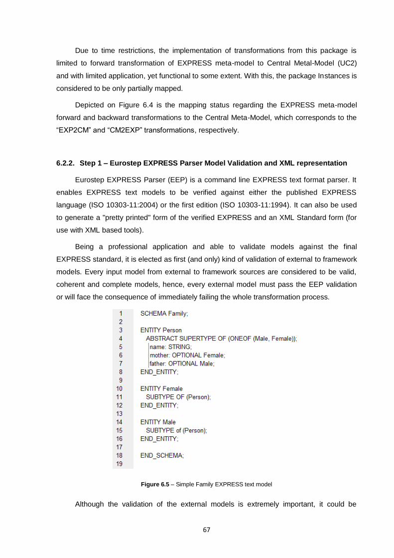
67
Due to time restrictions, the implementation of transformations from this package is
limited to forward transformation of EXPRESS meta-model to Central Metal-Model (UC2)
and with limited application, yet functional to some extent. With this, the package Instances is
considered to be only partially mapped.
Depicted on Figure 6.4 is the mapping status regarding the EXPRESS meta-model
forward and backward transformations to the Central Meta-Model, which corresponds to the
“EXP2CM” and “CM2EXP” transformations, respectively.
6.2.2. Step 1 – Eurostep EXPRESS Parser Model Validation and XML representation
Eurostep EXPRESS Parser (EEP) is a command line EXPRESS text format parser. It
enables EXPRESS text models to be verified against either the published EXPRESS
language (ISO 10303-11:2004) or the first edition (ISO 10303-11:1994). It can also be used
to generate a "pretty printed" form of the verified EXPRESS and an XML Standard form (for
use with XML based tools).
Being a professional application and able to validate models against the final
EXPRESS standard, it is elected as first (and only) kind of validation of external to framework
models. Every input model from external to framework sources are considered to be valid,
coherent and complete models, hence, every external model must pass the EEP validation
or will face the consequence of immediately failing the whole transformation process.
Figure 6.5 – Simple Family EXPRESS text model
Although the validation of the external models is extremely important, it could be
68
bypassed by simply ignoring errors at each transformation stage. Yet, the use of EEP is
justified with other extremely important feature: the XML tag formatting export. The process
of XML injection and extraction for EXPRESS models is not a simple task (Step 2), but the
simplest way to achieve it is starting with a XML formatted model. At the current date does
not exist a public EXPRESS text to MOF model instance available, so it had to be developed
bottom up from the workflow to the transformations. With all this in mind, EEP was the
rational choice to interface the external models with the framework, being able to complete
two critical steps with just one tool / step. Additionally, EEP (which current version is 1.3.34)
is pre-compiled for the three most used operating systems: Windows (2000, XP, Vista, 7,
Server 2003 and 2008), Linux (libc version 6 dependent) and Mac OSX (10.4.8 or later),
which allows the same multiplatform support like Eclipse.
Figure 6.5 depicts an input EXPRESS text model to the EEP validator. From now on,
throughout all steps, all input models for current step‟s explanation will be the output of the
previous step (except otherwise explicitly identified). The output of EEP after the input of the
model in Figure 6.5 is the XML formatted text depicted in Figure 6.6.
Figure 6.6 – Simple Family EXPRESS XML text model (output of EEP)
6.2.3. Step 2 – EXPRESS Injector
The transformations which will implement the mappings defined on Step 0 must be
applied to instances of MOF Model (XMI serialised), and the input EXPRESS models are in
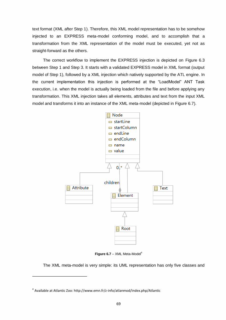
69
text format (XML after Step 1). Therefore, this XML model representation has to be somehow
injected to an EXPRESS meta-model conforming model, and to accomplish that a
transformation from the XML representation of the model must be executed, yet not as
straight-forward as the others.
The correct workflow to implement the EXPRESS injection is depicted on Figure 6.3
between Step 1 and Step 3. It starts with a validated EXPRESS model in XML format (output
model of Step 1), followed by a XML injection which natively supported by the ATL engine. In
the current implementation this injection is performed at the “LoadModel” ANT Task
execution, i.e. when the model is actually being loaded from the file and before applying any
transformation. This XML injection takes all elements, attributes and text from the input XML
model and transforms it into an instance of the XML meta-model (depicted in Figure 6.7).
Figure 6.7 – XML Meta-Model4
The XML meta-model is very simple: its UML representation has only five classes and
4 Available at Atlantic Zoo: http://www.emn.fr/z-info/atlanmod/index.php/Atlantic
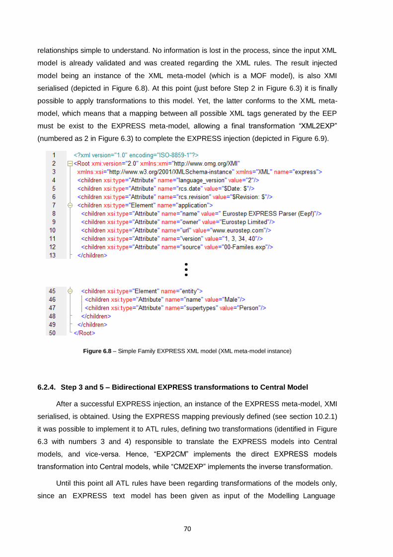
70
relationships simple to understand. No information is lost in the process, since the input XML
model is already validated and was created regarding the XML rules. The result injected
model being an instance of the XML meta-model (which is a MOF model), is also XMI
serialised (depicted in Figure 6.8). At this point (just before Step 2 in Figure 6.3) it is finally
possible to apply transformations to this model. Yet, the latter conforms to the XML meta-
model, which means that a mapping between all possible XML tags generated by the EEP
must be exist to the EXPRESS meta-model, allowing a final transformation “XML2EXP”
(numbered as 2 in Figure 6.3) to complete the EXPRESS injection (depicted in Figure 6.9).
Figure 6.8 – Simple Family EXPRESS XML model (XML meta-model instance)
6.2.4. Step 3 and 5 – Bidirectional EXPRESS transformations to Central Model
After a successful EXPRESS injection, an instance of the EXPRESS meta-model, XMI
serialised, is obtained. Using the EXPRESS mapping previously defined (see section 10.2.1)
it was possible to implement it to ATL rules, defining two transformations (identified in Figure
6.3 with numbers 3 and 4) responsible to translate the EXPRESS models into Central
models, and vice-versa. Hence, “EXP2CM” implements the direct EXPRESS models
transformation into Central models, while “CM2EXP” implements the inverse transformation.
Until this point all ATL rules have been regarding transformations of the models only,
since an EXPRESS text model has been given as input of the Modelling Language
…
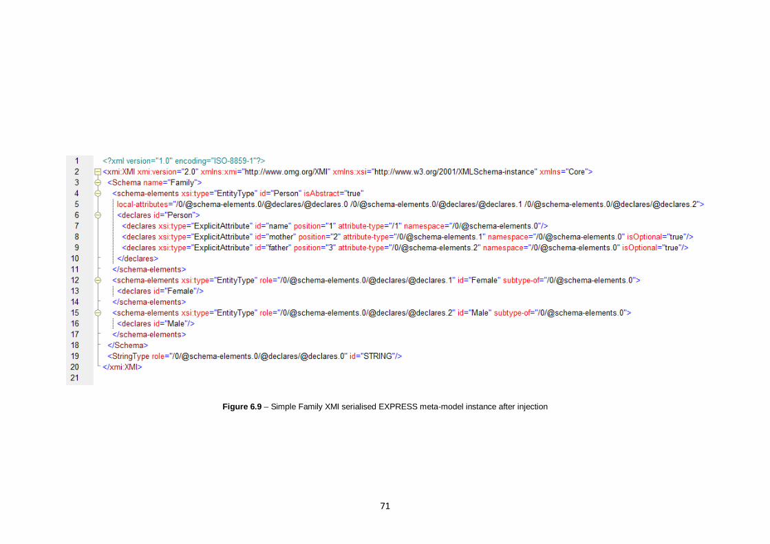
71
Figure 6.9 – Simple Family XMI serialised EXPRESS meta-model instance after injection
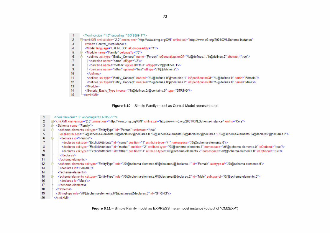
72
Figure 6.10 – Simple Family model as Central Model representation
Figure 6.11 – Simple Family model as EXPRESS meta-model instance (output of “CM2EXP”)

73
Harmonisation Layer. But since both Central Meta-Model and EXPRESS meta-model can
represent either models and/or model instances, it is possible to inject those instances on the
XMI serialised representation of the EXPRESS models. To support the feasibility of both
model and data transformations, only “EXP2CM” has specific rules to also transform those
model instances into the corresponding instances of the Central model (envisaged in UC2).
This way, the implementation validates both the possibility to use model instances closely to
the corresponding models of the EXPRESS meta-model and Central Meta-Model, yet limited
in one direction of transformation.
The Central model instance of the original EXPRESS model (output of the
transformation “EXP2CM” depicted in Figure 6.10) is the output intended to the Inter-
Enterprise Harmonisation Layer (depicted in Figure 5.1), representing the original model
(with some possible loss of information) but translated to the common Central Meta-Model
high abstraction concepts. After this layer treats the semantic and model mappings (UC2),
the returning Central Model (which by the workflow depicted on Figure 5.2 corresponds to
the model of the opposite enterprise which one is referencing as being the original input
model) will act as input of the Modelling Language Harmonisation Layer. This means that is
possible to transform it back into a readable and understandable format for the destination
enterprise. So far, only transformations which exports from the Central Meta-Model to
EXPRESS are available. This process consists in transforming the Central Model
representation to an EXPRESS model (transformation “CM2EXP”, numbered as 4 in Figure
6.3), but due to limited time it is not instances enabled (an example of the output of this
transformation is depicted in Figure 6.11).
6.2.5. Step 4 – Central Models to Central Models (UC2)
Central Models to Central Models transformations are enabled and envisaged by UC2,
and used to harmonise both structurally and semantically (Inter-Enterprise Harmonisation
Layer responsibility). Each transformation (identified as Step 4 in Figure 6.3) has to be
specifically designed for a known and static source Central Model and to a given static
destination Central Model, regarding the structural and semantic mappings defined by the
Inter-Enterprise Harmonisation Layer specifically for that pair of Central Models.
6.2.6. Step 6 – Exporting EXPRESS Models back to text and/or XML
Any model represented as an instance of the EXPRESS meta-model, has two possible
transformations to be exported from the XMI serialisation. It can be exported back to the
original XML or text format, by a model to model transformation (“EXP2XML” plus XML
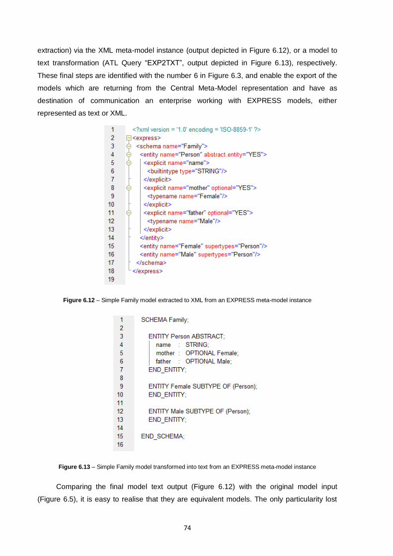
74
extraction) via the XML meta-model instance (output depicted in Figure 6.12), or a model to
text transformation (ATL Query “EXP2TXT”, output depicted in Figure 6.13), respectively.
These final steps are identified with the number 6 in Figure 6.3, and enable the export of the
models which are returning from the Central Meta-Model representation and have as
destination of communication an enterprise working with EXPRESS models, either
represented as text or XML.
Figure 6.12 – Simple Family model extracted to XML from an EXPRESS meta-model instance
Figure 6.13 – Simple Family model transformed into text from an EXPRESS meta-model instance
Comparing the final model text output (Figure 6.12) with the original model input
(Figure 6.5), it is easy to realise that they are equivalent models. The only particularity lost

75
during all the process of being transformed from text to a Central Model and back to text,
was the EXPRESS rule “SUPERTYPE OF (ONEOF (Male, Female))”, which belongs to the
“Expressions” EXPRESS package. This package was explicitly not mapped, thus there is no
surprise on the loss itself. On the other hand, since the entity “Person” remains as an
abstract entity on the output, there is no great loss of information.
While this implementation is focused on the input and output of EXPRESS models on
Modelling Language Harmonisation Layer, in a real collaboration scenario the output
modelling language would usually be different from the input‟s one.

76
77
7. IMPLEMENTATION TESTING AND HYPOTHESIS VALIDATION
In this section will be addressed the implementation testing, validating that the
specifications defined in section 10.1 where in fact met. Testing is the process of trying to
find errors in a system implementation by means of experimentation. This experimentation is
usually carried out in a special environment, where normal and exceptional use is simulated.
The aim of testing is to gain confidence that during normal use the system will work
satisfactory, since testing of realistic systems can never be exhaustive, because systems can
only be tested during a restricted period of time. On the other hand, testing cannot ensure
complete correctness of an implementation since it can only show the presence of errors, not
their absence [106]. Although a successful testing applied to the proof-of-concept does not
mean that it is ready to work as a commercial software (since it was never intended to be
one), it can validate that all major functions and modules are correctly (or not) working and
with that validate the feasibility of a future full implementation.
In the next sections will be presented some methodologies and the one which has
been chosen to best approach the test definition applied to this particular proof-of-concept
implementation. After some tests formalisation will be presented its results based on the
performance of the various tested modules. Finally, in the last section a scientific context
validation is presented.
7.1. Testing Methodologies
There are many testing methodologies available to test software engineering, many of
them are abstract concepts like white / black / grey box testing, unit testing, conformance
testing, etc. Testing in general but particularly in software testing [107] [108], functional and
structural testing are distinguished from each other.
Structural testing is based on the internal structure of a computer program, where all
program code is analysed and each line executed at least one time, covering all possible
paths of execution. This type of analysis is also known as the white-box testing, where tests
are derived from the program code. On the other hand, functional testing is about testing the
externally observed phenomena of a program, regarding to its specification. Also known as
black-box testing, in functional testing the functionality is evaluated by observing the box
externally with no reference of its internal details or implementation at all. Since the
functional tests are derived from the specification, the main goal is to analyse if the product is
in fact working accordingly with the specification. Consequently, due to the nature of each of
78
these testing methods, while structural testing is used in the early stages of the software
development, functional tests are more often concentrated in the later stages of
development.
Conformance testing is a kind of black-box testing, being only concerned with the
correctness of a protocol implementation. This means that a developed software is evaluated
regarding to its specification and it correct implementation, directly implying that correct, valid
and clear specification was provided in advance. Evaluating the correctness of a
specification is referred to as “protocol validation” and involves checking that the
implementation correctly behaves accordingly to the specification and the intended behaviour
is indeed present. One problem regarding this procedure is inherently close to the
specification: if it contains a design error and if the conformance testing process is correctly
performed, each conforming implementation will have that same error [106].
To define proved methods which apply these testing concepts, many standards were
defined and revised throughout the years based on the expertise of using them and their
practical results. On the other hand, sometimes a superimposition of a multitude of these is
used in order to cover the necessities of a larger or more specific project. An example of this
is the evaluation method and its definition which was used on the European Project iSurf
[109], since it was based on the SQuaRE series of standards.
7.1.1. iSurf Functional and Non-Functional Evaluation Methodology
The iSurf European Project is integrated in the European Community's Seventh
Framework Programme (FP7/2007-2013), and has as main objective the development of “an
environment [which] needs to be created to facilitate the collaborative exploitation of
distributed intelligence of multiple trading partners in order to better plan and fulfil the
customer demand in the supply chain” [109]. As a response to this need, the iSURF project
(“An Interoperability Service Utility for Collaborative Supply Chain Planning across Multiple
Domains Supported by RFID Devices”) provides a knowledge-oriented inter-enterprise
collaboration environment to SMEs to share information on the supply chain visibility,
individual sales and order forecast of companies, current status of the products in the
manufacturing and distribution process, and the exceptional events that may affect the
forecasts in a secure and controlled way.
The iSurf evaluation and testing framework follows the standard process defined on the
evaluation reference model and guide ISO/IEC CD 25040 [110] of the SQuaRE series of
standards and not limited to. Some of the used standards were: ISO/IEC 9126-1 [111],
ISO/IEC 14598-1 [112], ISO/IEC CD 25010 [113], ISO/IEC CD 25030 [114], ISO/IEC 14598-

79
5 [115], ISO/IEC CD 8402-1 [116] and ISO 9241 [117]. ISO/IEC CD 25040 details the
activities and tasks providing their purposes, outcomes and complementary information that
can be used to guide a software product quality evaluation. The outcomes of applying a
standard process approach for the evaluation activities in iSurf are the repeatability,
reproducibility, impartiality and objectivity of all process.
Deliverable series 8 of the iSurf [118] project present the principal standard steps for
iSurf evaluation strategy (prepare, establish, specify, design, execute, report) and also
describe in detail the procedures used to generate the evaluation criteria that were applied
for the functional and non-functional characteristics (functionality, reliability, usability,
efficiency, maintainability and portability). The project also identified the following techniques
which were applied for evaluation of the iSurf components and architecture: functional tests,
unit tests, fault tolerance analysis, user interface analysis, execution time measurements,
documentation inspection and analysis of software installation procedures.
These techniques and their evaluation criteria were modularised as recommended in
ISO/IEC 25041 former ISO/IEC 14598-6 [119], in order to have a structured set of
instructions and data used for the evaluation. It specifies the evaluation methods applicable
to evaluate a quality characteristic (functional / non-functional) identifying the evidence it
needs, defining the elementary evaluation procedure and the format for reporting the
measurements resulting from the application of the technique.
Functional and non-functional evaluation criteria modules provide a flexible and
structured approach to define criteria for monitoring the quality of intermediate products
during the development process and for evaluation of final products. The purpose of using
evaluation modules is to ensure that software evaluations can be repeatable, reproducible
and objective.
These modules define a set structured instructions and data used for an evaluation. It
specifies the criteria applicable to evaluate a quality characteristic and it identifies the
evidence of it needs. It also defines the elementary evaluation procedure and the format for
reporting the measurements resulting from the application of the technique.
The modules described specify the criteria for making the measurement as well as the
preconditions and accuracy of the measurement. The aim is to make the various aspects
(principles, metrics, activities, etc.) of evaluation visible and to show how they are handled.
They are documented as specified on the standard ISO/IEC 14598-6:
1. Provides formal information about the evaluation module and gives an
introduction to the evaluation technique described in the evaluation module;
2. Defines the scope of applicability of the evaluation module;
80
3. Specifies the input products required for the evaluation and defines the data to
be collected and measures to be calculated;
4. Contains information about how to interpret measurement results.
The evaluation modules define the criteria for the evaluation of the iSurf components
considering the functional and non-functional quality characteristics specified on the SQuaRE
series of standards:
Functional:
Functionality: Functional Test Cases;
Functionality: Unit Tests.
Non-functional:
Reliability: Fault tolerance Analysis;
Usability: User interface;
Efficiency: Execution time measurement;
Maintainability: Inspection of development documentation;
Portability: Analysis of software installation procedures.
7.1.2. ISO/IEC 9646 (ITU-T X.290) – Framework and Methodology for Conformance
Testing of Implementations of OSI and ITU Protocols
ISO together with International Telecommunication Union – Telecommunication
Standardisation Sector (ITU-T), developed a standard for conformance testing of Open
Systems, in order to standardise the way implementations of protocols are tested and
verified they are conforming the specifications. One way to check if implementations of a
protocol are correct is through tests based on generally accepted principles, using generally
accepted tests which lead to generally accepted test results. To cover this, ISO and ITU-T
developed ISO/IEC 9646 (“Open Systems Interconnection (OSI) Conformance Testing
Methodology and Framework” [120]) which applies generally accepted tests to evaluate
conformance testing of Open Systems. The general purpose of this standard is “to define the
methodology, to provide a framework for specifying conformance test suites, and to define
the procedures to be followed during testing”, which leads to “comparability and wide
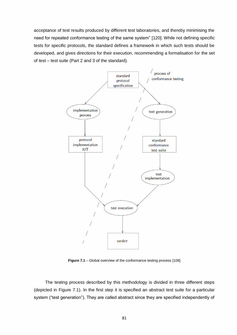
81
acceptance of test results produced by different test laboratories, and thereby minimising the
need for repeated conformance testing of the same system” [120]. While not defining specific
tests for specific protocols, the standard defines a framework in which such tests should be
developed, and gives directions for their execution, recommending a formalisation for the set
of test – test suite (Part 2 and 3 of the standard).
Figure 7.1 – Global overview of the conformance testing process [106]
The testing process described by this methodology is divided in three different steps
(depicted in Figure 7.1). In the first step it is specified an abstract test suite for a particular
system (“test generation”). They are called abstract since they are specified independently of
82
the implementation. In the second step consists in the realisation of the tests in order to be
executed (“test implementation”). Here, the specific implementation is taken into account,
and the abstract tests are transformed / adapted in order to be possible to apply them to the
specific implementation. The third and last step consists in the test execution and analysis of
the results, determining a verdict of the implementation conformity with the original
specification [106].
7.1.3. Tree and Tabular Combined Notation (TTCN) – Test Notation Standard
The Tree and Tabular Combined Notation (TTCN [121]) is a notation standardised by
the ISO/IEC 9646-1 for the specification of tests for communicating systems and has been
developed within the framework of standardised conformance testing. Based on the
black-box testing model, the tests are defined through tables which are divided in general
description, constraints, behaviour and verdict.
With TTCN, the test behaviour is defined by a sequence of events which represent the
test per se. The sequence of events can be approached as tree, containing branches of
actions based on evaluation of the system output after one (or a series of) executed event.
Each event has its own respective level of indentation and can be of one of two types: action
or question. Actions are preceded by an exclamation point before its brief description, and
represent actions performed on the System Under Test (SUT). Questions are preceded by
an interrogation point, and represent evaluations of the output of the SUT after one or more
actions are completed. Since the answer can be positive or negative, multiple questions can
exist at the same indentation level, covering all possible outputs of the system. After a
completion of a TTCN test table a verdict must be deliberate: “Success”, “Failure” or
“Inconclusive”. This verdict is based on the sequence of events which travel through the tree,
and was conditioned by the outputs of the system and evaluated by the question events.
Depicted in Table 7.1 is a simplified example of a phone call can establishment
evaluation. After a series of actions and evaluations (questions events) a different verdict is
attained. The table can textually read as:
1. The user picks up the headphone;
2. Tests if the dialling tone is present;
3. If the dialling tone is present, then the user must dial the other phone‟s number.
Otherwise, if the dialling tone is absent, the verdict is a “Failure” of the
possibility of establishing a phone call;
4. If there is a calling tone after dialling the number, the user may test if the line is
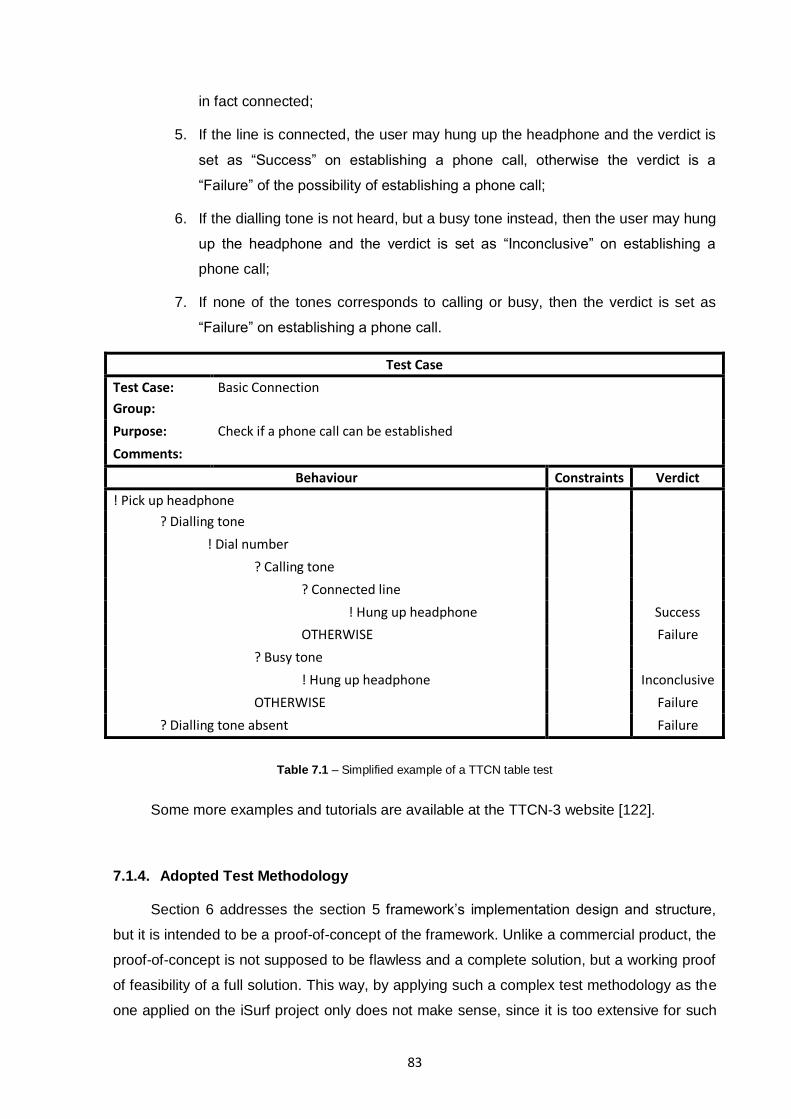
83
in fact connected;
5. If the line is connected, the user may hung up the headphone and the verdict is
set as “Success” on establishing a phone call, otherwise the verdict is a
“Failure” of the possibility of establishing a phone call;
6. If the dialling tone is not heard, but a busy tone instead, then the user may hung
up the headphone and the verdict is set as “Inconclusive” on establishing a
phone call;
7. If none of the tones corresponds to calling or busy, then the verdict is set as
“Failure” on establishing a phone call.
Test Case
Test Case: Basic Connection
Group:
Purpose: Check if a phone call can be established
Comments:
Behaviour Constraints Verdict
! Pick up headphone
? Dialling tone
! Dial number
? Calling tone
? Connected line
! Hung up headphone Success
OTHERWISE Failure
? Busy tone
! Hung up headphone Inconclusive
OTHERWISE Failure
? Dialling tone absent Failure
Table 7.1 – Simplified example of a TTCN table test
Some more examples and tutorials are available at the TTCN-3 website [122].
7.1.4. Adopted Test Methodology
Section 6 addresses the section 5 framework‟s implementation design and structure,
but it is intended to be a proof-of-concept of the framework. Unlike a commercial product, the
proof-of-concept is not supposed to be flawless and a complete solution, but a working proof
of feasibility of a full solution. This way, by applying such a complex test methodology as the
one applied on the iSurf project only does not make sense, since it is too extensive for such
84
kind of implementation. With this, a mix of validation tests was chosen in order to try to
validate the proof-of-concept implementation.
Based on the iSurf test methodology and the TTCN tables proposed by ISO/IEC 9646,
a series of functional test cases and unit tests described by TTCN tables were designed and
applied to the various units of the implementation steps (depicted in Figure 6.3). On the other
hand, non-functional tests such as reliability, efficiency and portability were also addressed.
All the results and tests definitions are published in section 7.3.
7.2. Requirements and Functionalities Evaluation
In section 10.1 the requirement and functionalities of the system are presented. These
were defined during the framework design and were the main objectives of a full
implementation of the framework. In order to evaluate the extent of the proof-of-concept
implementation, a mapping between the requirements and functionalities of the system and
the implementation are presented:
Requirements:
The user should be able to import models (OWL, XSD, UML, EXPRESS):
model imports are only available for EXPRESS models. Both EXPRESS and
XML Schema meta-models were mapped to the Central Meta-Model, yet only
the EXPRESS mappings were implemented through a series of six
transformations (see Figure 6.3) plus an external parsing program (EEP,
section 6.2.2);
The system should have a Central Model able to represent all foreign
models languages specificities, i.e. language independent: it was defined a
Central Meta-Model able to represent high abstraction level concepts which
were comprehensive enough to support at least EXPRESS and XML Schema
concepts with minimal loss of expressiveness;
The system should have all foreign models interconnected with the
Central Model, at the Meta-Model Level: mappings between the meta-models
of EXPRESS and XML Schema were proposed to interconnect with the Central
Meta-Model (see section 10.2);
o Model morphism should be explicit (not embedded in the code): all
model morphisms implementations were designed using ATLAS
Transformation Language (ATL). This way, each morphism is isolated

85
from the others, in different code and compiled files, yet not embed in an
object oriented language solution like a JAVA program. Independent
compiled files means that each transformation is platform independent,
yet dependent of an ATL transformation executor;
o Transformation should be executed automatically (e.g. ATL): since
all transformations were implemented in ATL, transformations are
always automatically executed given an input and a transformation
engine which executes them;
o Mediator should be able to have a link to the model morphism
defined: each transformation is physically separated from the others,
since each one has its own code and compiled files. This way, the
mediator will be able to differentiate each transformation by linking
different files representing the multiple transformations available and
direction of transformation.
Functionalities:
Transform foreign models into a Central Model: thought the execution of
Steps 1 to 3 of the proof-of-concept implementation (see Figure 6.3) is possible
to transform EXPRESS foreign models into a Central Model;
Transform Central Models into foreign models: thought the execution of
Steps 5 and 6 of the proof-of-concept implementation (see Figure 6.3) is
possible to transform Central Models into a EXPRESS foreign model;
Through the analysis of these mappings is possible to conclude that, with the exception
of the first requirement, all requirements and functionalities are present on the
proof-of-concept implementation.
Regarding the first requirement, the multitude of import model languages was not
possible to be implemented due to time limitation. With this, was not possible to define and
implement all those modelling languages mappings and transformations. While the
EXPRESS modelling language is fully supported (meta-models mapping and implementation
of the required transformations) and the XML Schema meta-model mapping is also defined
(see section 10.2.2), the author believes that the Central Meta-Model defined is complete
enough to support the other modelling languages proposed (OWL and UML).
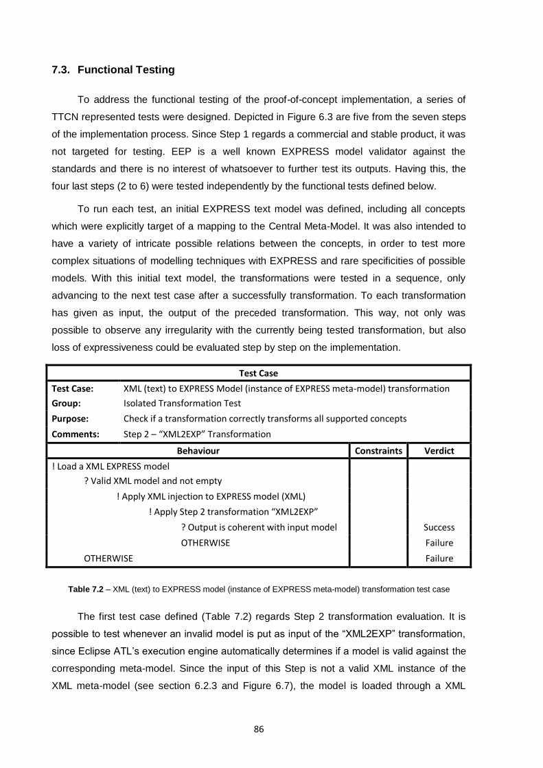
86
7.3. Functional Testing
To address the functional testing of the proof-of-concept implementation, a series of
TTCN represented tests were designed. Depicted in Figure 6.3 are five from the seven steps
of the implementation process. Since Step 1 regards a commercial and stable product, it was
not targeted for testing. EEP is a well known EXPRESS model validator against the
standards and there is no interest of whatsoever to further test its outputs. Having this, the
four last steps (2 to 6) were tested independently by the functional tests defined below.
To run each test, an initial EXPRESS text model was defined, including all concepts
which were explicitly target of a mapping to the Central Meta-Model. It was also intended to
have a variety of intricate possible relations between the concepts, in order to test more
complex situations of modelling techniques with EXPRESS and rare specificities of possible
models. With this initial text model, the transformations were tested in a sequence, only
advancing to the next test case after a successfully transformation. To each transformation
has given as input, the output of the preceded transformation. This way, not only was
possible to observe any irregularity with the currently being tested transformation, but also
loss of expressiveness could be evaluated step by step on the implementation.
Test Case
Test Case: XML (text) to EXPRESS Model (instance of EXPRESS meta-model) transformation
Group: Isolated Transformation Test
Purpose: Check if a transformation correctly transforms all supported concepts
Comments: Step 2 – “XML2EXP” Transformation
Behaviour Constraints Verdict
! Load a XML EXPRESS model
? Valid XML model and not empty
! Apply XML injection to EXPRESS model (XML)
! Apply Step 2 transformation “XML2EXP”
? Output is coherent with input model Success
OTHERWISE Failure
OTHERWISE Failure
Table 7.2 – XML (text) to EXPRESS model (instance of EXPRESS meta-model) transformation test case
The first test case defined (Table 7.2) regards Step 2 transformation evaluation. It is
possible to test whenever an invalid model is put as input of the “XML2EXP” transformation,
since Eclipse ATL‟s execution engine automatically determines if a model is valid against the
corresponding meta-model. Since the input of this Step is not a valid XML instance of the
XML meta-model (see section 6.2.3 and Figure 6.7), the model is loaded through a XML
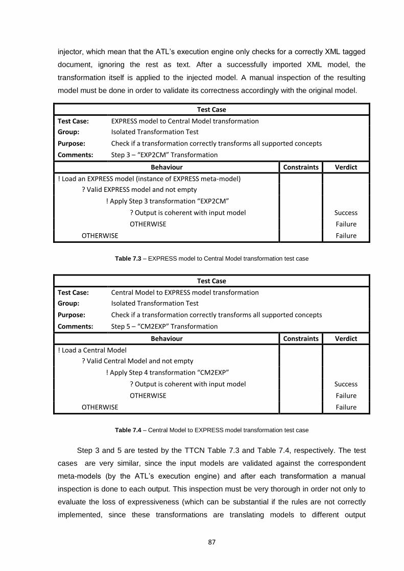
87
injector, which mean that the ATL‟s execution engine only checks for a correctly XML tagged
document, ignoring the rest as text. After a successfully imported XML model, the
transformation itself is applied to the injected model. A manual inspection of the resulting
model must be done in order to validate its correctness accordingly with the original model.
Test Case
Test Case: EXPRESS model to Central Model transformation
Group: Isolated Transformation Test
Purpose: Check if a transformation correctly transforms all supported concepts
Comments: Step 3 – “EXP2CM” Transformation
Behaviour Constraints Verdict
! Load an EXPRESS model (instance of EXPRESS meta-model)
? Valid EXPRESS model and not empty
! Apply Step 3 transformation “EXP2CM”
? Output is coherent with input model Success
OTHERWISE Failure
OTHERWISE Failure
Table 7.3 – EXPRESS model to Central Model transformation test case
Test Case
Test Case: Central Model to EXPRESS model transformation
Group: Isolated Transformation Test
Purpose: Check if a transformation correctly transforms all supported concepts
Comments: Step 5 – “CM2EXP” Transformation
Behaviour Constraints Verdict
! Load a Central Model
? Valid Central Model and not empty
! Apply Step 4 transformation “CM2EXP”
? Output is coherent with input model Success
OTHERWISE Failure
OTHERWISE Failure
Table 7.4 – Central Model to EXPRESS model transformation test case
Step 3 and 5 are tested by the TTCN Table 7.3 and Table 7.4, respectively. The test
cases are very similar, since the input models are validated against the correspondent
meta-models (by the ATL‟s execution engine) and after each transformation a manual
inspection is done to each output. This inspection must be very thorough in order not only to
evaluate the loss of expressiveness (which can be substantial if the rules are not correctly
implemented, since these transformations are translating models to different output
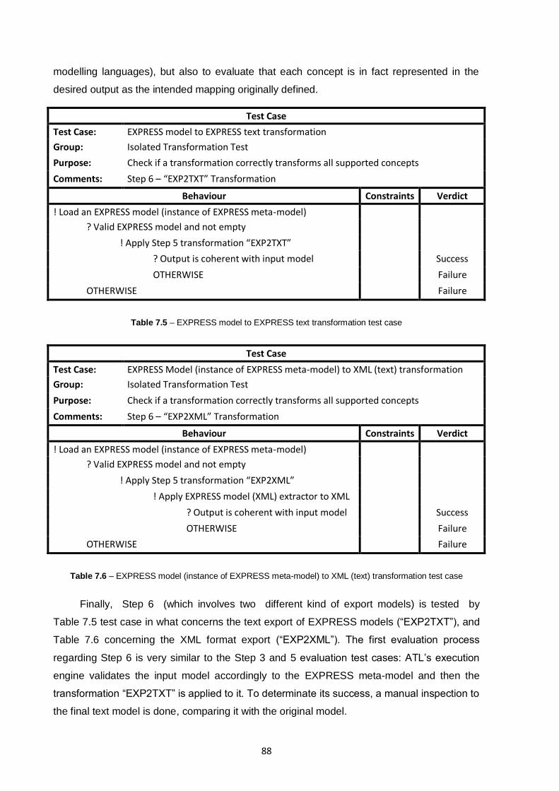
88
modelling languages), but also to evaluate that each concept is in fact represented in the
desired output as the intended mapping originally defined.
Test Case
Test Case: EXPRESS model to EXPRESS text transformation
Group: Isolated Transformation Test
Purpose: Check if a transformation correctly transforms all supported concepts
Comments: Step 6 – “EXP2TXT” Transformation
Behaviour Constraints Verdict
! Load an EXPRESS model (instance of EXPRESS meta-model)
? Valid EXPRESS model and not empty
! Apply Step 5 transformation “EXP2TXT”
? Output is coherent with input model Success
OTHERWISE Failure
OTHERWISE Failure
Table 7.5 – EXPRESS model to EXPRESS text transformation test case
Test Case
Test Case: EXPRESS Model (instance of EXPRESS meta-model) to XML (text) transformation
Group: Isolated Transformation Test
Purpose: Check if a transformation correctly transforms all supported concepts
Comments: Step 6 – “EXP2XML” Transformation
Behaviour Constraints Verdict
! Load an EXPRESS model (instance of EXPRESS meta-model)
? Valid EXPRESS model and not empty
! Apply Step 5 transformation “EXP2XML”
! Apply EXPRESS model (XML) extractor to XML
? Output is coherent with input model Success
OTHERWISE Failure
OTHERWISE Failure
Table 7.6 – EXPRESS model (instance of EXPRESS meta-model) to XML (text) transformation test case
Finally, Step 6 (which involves two different kind of export models) is tested by
Table 7.5 test case in what concerns the text export of EXPRESS models (“EXP2TXT”), and
Table 7.6 concerning the XML format export (“EXP2XML”). The first evaluation process
regarding Step 6 is very similar to the Step 3 and 5 evaluation test cases: ATL‟s execution
engine validates the input model accordingly to the EXPRESS meta-model and then the
transformation “EXP2TXT” is applied to it. To determinate its success, a manual inspection to
the final text model is done, comparing it with the original model.
89
The second evaluation process of Step 6 regards with exporting EXPRESS
meta-models instances to XML tagged representations. As usual, input model loading is
validated by the Eclipse ATL‟s executor engine against the EXPRESS meta-model. The
typical transformation “EXP2XML” is then applied to transform the model into an XML
meta-model instance. The last action is then applied to this model, extracting it to a XML
tagged model. Once this is obtained, a manual inspection is then applied to the output and
validated against the original model.
Analysing the output of each of the above transformations, all of them were evaluated
as a success, based on the corresponding TTCN test case tables. Hence, the
transformations are indeed capable of representing the mappings defined in section 10.2.1,
validating the feasibility of an automated EXPRESS text model to its Central Model
representation, and back to EXPRESS text model. All intricate relations and most important
model representation forms were preserved. On the other hand, by analysing the inherent
loss of expressiveness, a few remarks can be enumerated, since these transformations are
not completely lossless:
1. An initially EXPRESS concept defined as being an “AggregationType”,
specifically as “SETType”, “LISTType”, “BAGType” and “ARRAYType” are
exclusively mapped to the Central Meta-Model “Aggregation_Type”. By not
being able to annotate the original EXPRESS type, it will lose this information
and therefore a loss of expression is present. When the inverse transformation
“CM2EXP” occurs, there is no way of differentiating if the data contained on
such typed concept is in fact from a Bag, List, Set or Array. To avoid further
misconception of the data, the transformed “Aggregation_Type” will always be
instantiated as a “BAGType” of the EXPRESS meta-model, since it is the least
restrictive type out of the four;
2. Another loss of expressiveness occurs when regarding EXPRESS abstract
properties, since the Central Meta-Model is only able to deal with abstraction of
“Entity_Concept” concepts, which maps with the “EntityType” concepts of the
EXPRESS meta-model;
3. The “USE” and “REFERENCE” links to foreign schemas are not mapped to the
Central Meta-Model, hence, its semantic value are lost and when in attempt to
export a Central Model to EXPRESS model, the “USE” link is automatically
associated for references to other schemas.
Since all these functional test cases where executed using a synthetic model
representation, with sole function of being able to test from simple relations to intricate in-
90
model relations, there was an urge to test with a model which would in fact represent a real
use case. On the other hand, all transformations were working as expected when analysed in
an independent way, but a complete test case from EXPRESS to Central model and back to
EXPRESS should be tested by automatically executing all the necessary transformations.
This way, and in order to validate the complete transformation cycle with a real application
model, a manipulated data standard as ISO TC184/SC4/WG12 N1177 – ISO/TS 10303-1060
“Product concept identification”, and a complete standard as ISO TC184/SC4/WG3 N2186 –
ISO/TS 10303-436 “AP236 Furniture Catalogue and Interior Design” (in EXPRESS ARM long
form) were given as text model input of the implementation proof-of-concept. Both were able
to be transformed into a Central Model instance and back again into EXPRESS text model
and XML model, without any critical application error or intra framework steps model
validation failure. The first standard was simple to manually validate the final output against
the original input. Regarding the second standard (a text file of 176KB and 5092 lines), due
to the model dimensions involved, it was not possible to completely evaluate the loss of
expressiveness which the model suffered, but induced by the results obtained with earlier
tests, there were nothing to expect but the ones presented before. This test validates a
transformation of a bigger model (than the ones used to validate the TTCN tables), without
compromising the reliability of the process.
7.4. Non-Functional Testing
Regarding non-functional testing, reliability, efficiency and portability can be addressed
in order to give a glimpse of what can be evaluated.
Reliability is the ability of the software to perform a required function under given
conditions for a given time interval. In general, software which is not doing what it is intended
to do is unavailable for its proper tasks [118]. Analysing the reliability of a system is not a
simple task, yet in what regards to the transformations executing engine, it either applies the
transformation or it does not. Given that no critical bug is known in the transformations
workflow (i.e. a bug which aborts a transformation), given an initial valid model (e.g. pre-
validated by EEP) the reliability is given by the execution engine itself, and not by the
transformations themselves. This way, given that ATL is currently in growing development,
and since it is not a final product, it is recommended that no human lives depend on an
implementation or workflow which includes Eclipse ATL execution engine. Nevertheless,
given the experience the author has, the software never crashed nor froze when defining and
executing any transformation or transformations workflow. To test reliability furthermore, it
was put as a model input a very large model (ISO TC184/SC4/WG3 N2186 – ISO/TS 10303-
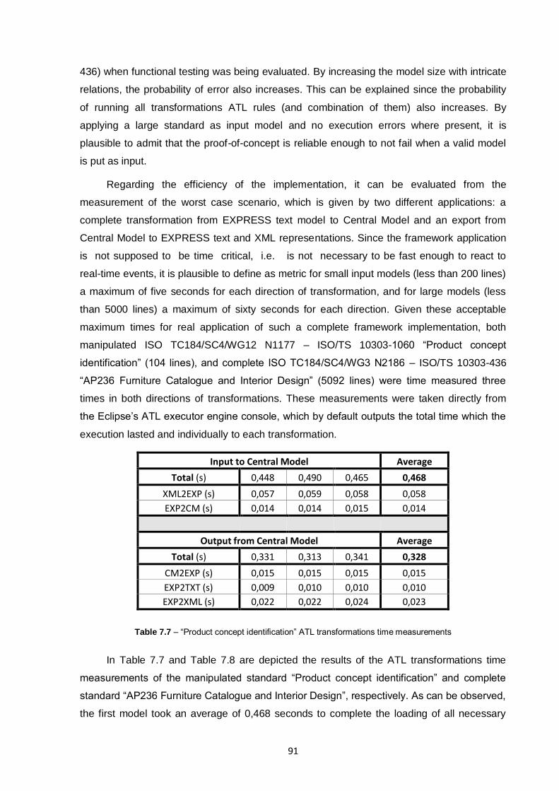
91
436) when functional testing was being evaluated. By increasing the model size with intricate
relations, the probability of error also increases. This can be explained since the probability
of running all transformations ATL rules (and combination of them) also increases. By
applying a large standard as input model and no execution errors where present, it is
plausible to admit that the proof-of-concept is reliable enough to not fail when a valid model
is put as input.
Regarding the efficiency of the implementation, it can be evaluated from the
measurement of the worst case scenario, which is given by two different applications: a
complete transformation from EXPRESS text model to Central Model and an export from
Central Model to EXPRESS text and XML representations. Since the framework application
is not supposed to be time critical, i.e. is not necessary to be fast enough to react to
real-time events, it is plausible to define as metric for small input models (less than 200 lines)
a maximum of five seconds for each direction of transformation, and for large models (less
than 5000 lines) a maximum of sixty seconds for each direction. Given these acceptable
maximum times for real application of such a complete framework implementation, both
manipulated ISO TC184/SC4/WG12 N1177 – ISO/TS 10303-1060 “Product concept
identification” (104 lines), and complete ISO TC184/SC4/WG3 N2186 – ISO/TS 10303-436
“AP236 Furniture Catalogue and Interior Design” (5092 lines) were time measured three
times in both directions of transformations. These measurements were taken directly from
the Eclipse‟s ATL executor engine console, which by default outputs the total time which the
execution lasted and individually to each transformation.
Input to Central Model Average
Total (s) 0,448 0,490 0,465 0,468
XML2EXP (s) 0,057 0,059 0,058 0,058
EXP2CM (s) 0,014 0,014 0,015 0,014
Output from Central Model Average
Total (s) 0,331 0,313 0,341 0,328
CM2EXP (s) 0,015 0,015 0,015 0,015
EXP2TXT (s) 0,009 0,010 0,010 0,010
EXP2XML (s) 0,022 0,022 0,024 0,023
Table 7.7 – “Product concept identification” ATL transformations time measurements
In Table 7.7 and Table 7.8 are depicted the results of the ATL transformations time
measurements of the manipulated standard “Product concept identification” and complete
standard “AP236 Furniture Catalogue and Interior Design”, respectively. As can be observed,
the first model took an average of 0,468 seconds to complete the loading of all necessary
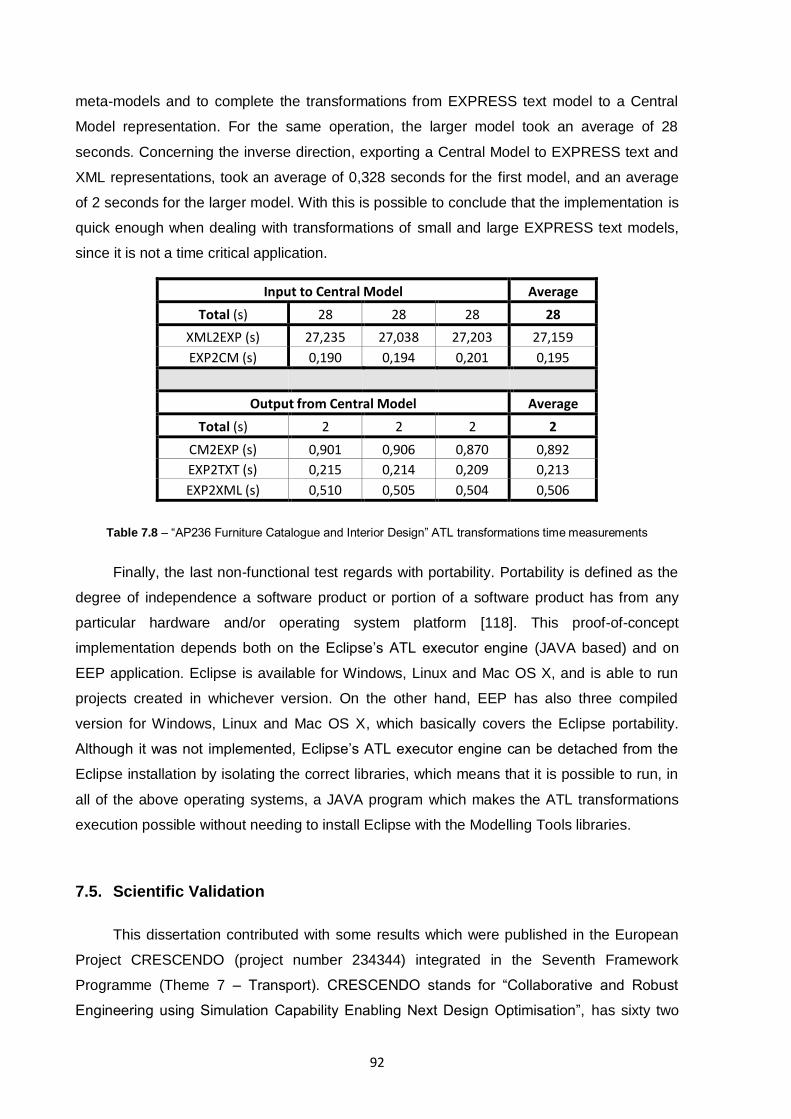
92
meta-models and to complete the transformations from EXPRESS text model to a Central
Model representation. For the same operation, the larger model took an average of 28
seconds. Concerning the inverse direction, exporting a Central Model to EXPRESS text and
XML representations, took an average of 0,328 seconds for the first model, and an average
of 2 seconds for the larger model. With this is possible to conclude that the implementation is
quick enough when dealing with transformations of small and large EXPRESS text models,
since it is not a time critical application.
Input to Central Model Average
Total (s) 28 28 28 28
XML2EXP (s) 27,235 27,038 27,203 27,159
EXP2CM (s) 0,190 0,194 0,201 0,195
Output from Central Model Average
Total (s) 2 2 2 2
CM2EXP (s) 0,901 0,906 0,870 0,892
EXP2TXT (s) 0,215 0,214 0,209 0,213
EXP2XML (s) 0,510 0,505 0,504 0,506
Table 7.8 – “AP236 Furniture Catalogue and Interior Design” ATL transformations time measurements
Finally, the last non-functional test regards with portability. Portability is defined as the
degree of independence a software product or portion of a software product has from any
particular hardware and/or operating system platform [118]. This proof-of-concept
implementation depends both on the Eclipse‟s ATL executor engine (JAVA based) and on
EEP application. Eclipse is available for Windows, Linux and Mac OS X, and is able to run
projects created in whichever version. On the other hand, EEP has also three compiled
version for Windows, Linux and Mac OS X, which basically covers the Eclipse portability.
Although it was not implemented, Eclipse‟s ATL executor engine can be detached from the
Eclipse installation by isolating the correct libraries, which means that it is possible to run, in
all of the above operating systems, a JAVA program which makes the ATL transformations
execution possible without needing to install Eclipse with the Modelling Tools libraries.
7.5. Scientific Validation
This dissertation contributed with some results which were published in the European
Project CRESCENDO (project number 234344) integrated in the Seventh Framework
Programme (Theme 7 – Transport). CRESCENDO stands for “Collaborative and Robust
Engineering using Simulation Capability Enabling Next Design Optimisation”, has sixty two
93
beneficiaries which includes Airbus SAS (France), ALTRAN Technologies S.A. (France),
Dassault Systèmes SA (France), Eurostep AB (Sweden), Fujitsu Systems Europe (United
Kingdom), Israel Aerospace Industries Ltd. (Israel), Rolls Royce Plc (United Kingdom), SAAB
Aktiebolag (Sweden), Siemens Product Lifecycle Management Software SAS (France),
UNINOVA – Instituto de Desenvolvimento de Novas Tecnologias (Portugal), Volvo Aero
Corporation AB (Sweden), among others. The project started in 2009, will last for 36 months
and addresses the Vision 20205 objectives for the aeronautical industry by contributing
significantly to the fulfilment of three specific targets of the aeronautical industry‟s Strategic
Research Agenda. CRESCENDO will develop the foundations for the Behavioural Digital
Aircraft (BDA), taking experience and results from VIVACE [123], and integrating these into a
federative system and building the BDA on top of them. Main components of the BDA are:
the Model Store, the Simulation Factory, the Quality Laboratory, and the Enterprise
Collaboration Capabilities. The results of the project will provide the aeronautics supply chain
with the means to realistically manage and mature the virtual product in the extended / virtual
enterprise with all of the requested functionality and components in each phase of the
product engineering life cycle. CRESCENDO will make its approach available to the
aeronautics supply chain via existing networks, information dissemination, training and
technology transfer actions [65].
As a direct result of this dissertation, contributions were made for CRESCENDO:
Contribution to Deliverable 5.2.1.1 which has as objective “developing the state-
of-the-art on the topics of semantic and model-based interoperability, exploring
sub-areas such as semantic mediation based on adaptive ontology, semantic
enrichment, model-driven development, model morphisms, and sustainability of
interoperability on complex dynamic networks” [65];
Elicitation and analysis of the requirements in Deliverable 5.2.2.2;
Formalisation of BDA Model store scenarios in Deliverable 5.2.2.3;
Model Store Architecture definition in Deliverable 5.2.3.2;
Definition of the generic scenarios in Deliverable 5.2.3.3.
Also validating the proposed framework (see section 5), a scientific publication was
accepted in the 17th ISPE International Conference on Concurrent Engineering, from 6th to
5European Aeronautics: A Vision for 2020 – http://www.cleansky.eu/sra/vision%202020.pdf

94
10th of September 2010 in Cracow – Poland, and it was published on the proceedings of the
conference:
Agostinho C., Correia F., and Jardim-Goncalves R., Interoperability of Complex
Business Networks by Language Independent Information Models, Accepted In:
17th ISPE International Conference on Concurrent Engineering (CE 2010). Sep
6-10, Cracow, Poland, 2010
95
8. CONCLUSIONS AND FUTURE WORK
Enterprises are changing the way they do business in order to successfully cope with
the global economic crisis that has established. Many of them still use traditional business
methods which are becoming glaringly outdated with poor efficiency. SMEs are more than
ever resorting to collaboration with other enterprises to be able to take advantage of new
market opportunities with narrower time windows and increasingly lower time-to-market.
Underlying to the increasing need for collaboration and since many of these enterprises still
operate with outdated systems and sometimes with no technology at all, they have a big
barrier to overcome in order to become interoperable with others. Many of these older
systems were designed on a need to serve the client, with proprietary standards which were
not prepared to be eventually interoperable with other systems. This is even more evident in
supply chains, where technological heterogeneous enterprises are more frequent since the
lower tiers do not have financial margins or technical capability to invest in new technology,
harming the performance of a possible collaboration network.
Adding even more complexity to the panorama, even those enterprises which in fact
have the capital to invest in new technology and hardware are not willing to change their
adopted models and semantics inherent to their business. On the other hand, every
enterprise has critical data which does not want others to know, mainly related with clients
and business opportunities, which invariably regards to their models. Yet, in order to
collaborate they have to open hand and share a great deal of information in the course of
their business activities, and constant adaptation of models and semantic to the high entropy
inherent to dynamic collaboration.
All this is a great barrier to the interoperability state which enterprises are constantly
looking for, but have serious regards about how and when to participate in collaboration
networks. This impasse of not knowing when and what to collaborate have a great impact
over enterprises‟ and global economy, due to the costs associated with poor or even lack of
interoperability. This is a problem which is addressed by the Europe ‟s 2020 strategy to guide
its economy out of the economic recession, by investing on innovation with programmes like
FP7 and FP8.
This dissertation presents a framework that provides a solution for collaborative
networks in need of a foundation to correctly enable interoperability. It is known that MDA
approach enables the use of models to represent ideas and concepts and supports
automatic transformations between the same levels of abstraction of these concepts, using
the available open standards to specify the models. With this, MDA with the widespread use
96
of open standards can be the basis for model sharing, from the high levels of the enterprises
internal organisation (such as the business level) to the lower data level. Therefore, the
proposed framework is MDA-based, and defines two levels of models translation: one
regarding the modelling language (Modelling Language Harmonisation Layer, see section
5.1.2.1) and another one regarding the semantics and models‟ structure (Inter-Enterprise
Harmonisation Layer, see section 5.1.2.2). While the first can be common to multiple
enterprises and needs to be implemented only once for each required modelling language on
the collaboration network, the second is focused on P2P communications of pairs of
enterprises.
Any enterprise willing to join the collaboration network with this framework does not
have to change in any way their models or legacy software. The interface to the framework is
implemented first by the model morphisms which integrates their legacy information systems
with a Central Meta-Model, and secondly by mapping their business models (represented as
Central Models) to the ones of other enterprises which have already implemented the
framework (both regarding the structure and semantics). All these framework‟s particularities
answer to the original research problem and questions defined in section 1.3.
By using P2P communications in the framework implementation, not only enterprises
can choose what information they are willing to share, but also they get to choose to whom
they will make available the models they choose to. This can be approached as a security
protection from exposing information which is restricted to a limited number of destination
enterprises, but not to all network. On the other hand, high dynamic collaboration networks
derive from enterprises often joining and leaving from the set. With P2P communication
enabled, it requires that only a joining enterprise has to implement the interface to the
framework to have a bidirectional communication with the rest of the set, leaving unaltered all
the other enterprises‟ interfaces and reducing the amount of entropy necessary to the
collaboration network converge to a complete state of interoperability. Thus, with this
framework, it is possible for an enterprise to belong to a number of disjoint collaboration
networks without compromising their information security or changing its legacy models and
software. This way, the framework delivers a simple, cheaper and quicker interoperability
state, when compared to what involves migrating software and models to adopt a common
central standard to attain the same interoperability level, in multiples collaboration networks.
Nevertheless, while the model morphisms implementing the Modelling Language
Harmonisation Layer need to be implemented only once (since the meta-models are
constant throughout the whole life of a given version of the standard) that can be not true
regarding the Inter-Enterprise Harmonisation Layer. Concerning the Central Model to Central
Model morphisms, it is directly connected on matching the structure of a source model to
97
with the structure of a destination model. If somehow one of the involving enterprises decides
to change a particular model structure which was previously available on the framework, it
can spoil all the morphisms associated with it, forcing all other interested parties to changes
those morphisms to regain the state of total interoperability. Thus, the higher volatile a
shared model is, the more entropy it will generate to the framework‟s interoperability state
once changed.
The model morphisms regarding the EXPRESS modelling language were implemented
to prove the framework feasibility, and the results of the tests applied to the Modelling
Language Harmonisation Layer (see section 7.3), proved that minimal loss of
expressiveness of an EXPRESS model round trip to a Central Model were present. These
losses were due to an incomplete package mapping and not from limitations from the model
morphisms, which validates the feasibility of a more complete solution.
8.1. Future Work
As for future work, a few things regarding the framework itself can be better refined.
The framework proposed is intended to have a graphical interface in which models and
meta-models concepts should be displayed and be able to be mapped visually. This would
allow a business specialist, rather than an ICT expert, to be able to map those concepts, not
only creating mappings between the used modelling language concepts to the Central Meta-
Model ones, but also the inter-enterprise model maps and semantic unification decisions.
This way the enterprise side is abstracted from the technology details and ATL rules which
should be generated based on the visual mappings, defined intuitively by the business
specialist focused on the enterprise‟s knowledge. On the other hand, an interface would ease
the mechanism of the framework readjusting its state of interoperability altered by evolution
of the enterprises‟ models, in the sense of rapidly allowing enterprises to correct the spoiled
morphisms.
Regarding the high level abstraction layers of the framework, the Inter-Enterprise
Harmonisation Layer which evaluates the semantic mismatches and common ontology
definition, should be completely defined and integrated with the results of this dissertation
(these semantic mismatches research work is being developed in parallel to this
dissertation), in order to reflect semantic changes in the model morphisms applied to Central
Models. Another concern related to this layer resides on the security of models and data
sharing throughout the collaborative network. It is not clearly specified how the results of
meta-models mapping from the Modelling Language Harmonisation Layer and the mappings
at the Inter-Enterprise Harmonisation Layer are going to be available at the enterprises side.

98
This means that while a manual distribution of the implemented morphisms is possible, an
automated distribution centre or even encryption keys should be taken in account in order to
limit the access to shared morphisms on enterprises demand, which otherwise could lead to
security holes of data and models. On the other hand, the Modelling Language
Harmonisation Layer is completely defined and specified for enabling more modelling
languages, but more languages should be applied. This would allow testing the interaction of
importing to Central Model with one and exporting with a different one. At this layer all
EXPRESS model transformations were implemented, but in what regards EXPRESS
instances only a small ATL rules validation part was implemented. The optional data
instances injection between step 2 and 3 depicted in Figure 5.2 is not a straight forward step
and would involve a specific workflow of complex transformations similar to the ones
involving the EXPRESS models injection. Data instances of EXPRESS are defined in ISO
10303-21 or 10303-28, which have a completely different text syntax and process of injecting
them to the EXPRESS meta-model. Due to time limitation this injection was made manually
to test a limited set of rules which transformed these EXPRESS instances in Central Model
ones.

99
9. REFERENCES
[1] Jardim-Goncalves R, Agostinho C, Malo P, and Steiger-Garcao A, “Harmonising technologies in conceptual models representation”, International Journal of Product Lifecycle Management 2007, Vol. 2, No. 2, pp.187–205, 2007
[2] Peppard J, Rylander A, “From Value Chain to Value Network: Insights for Mobile Operators”, European Management Journal. Vol.24, Issues 2-3, pp. 128-141, 2006
[3] Friedman T, “The World is Flat”, Farrar, Straus & Giroux, 2005 [4] Camarinha-Matos L, Afsarmanesh H, “Collaborative networked organizations: a research agenda
for emerging business models”, Springer, 2004 [5] Amin A, Cohendet P, “Architectures of knowledge: firms, capabilities, and communities”, Oxford
University Press, 2004 [6] Wilkinson I, Young L, “On cooperating: firms, relations and networks”, Journal of Business
Research, vol. 55, issue 2, pp.123-132, 2002 [7] Agostinho C and Jardim-Goncalves R, “Dynamic Business Networks: A Headache for
Sustainable Systems Interoperability”, Proceedings of the Confederated international Workshops and posters on: On the Move To Meaningful internet Systems: Adi, Cams, Ei2n, Isde, Iwssa, Monet, ontocontent, Odis, Orm, OTM Academy, Swws, Semels, Beyond Sawsdl, and COMBEK 2009
[8] Watson S, “Material offshore sourcing undergoes standardization”, SCBIZ Magazine, April-May, 2008
[9] Tae-Young K, Sunjae L, Kwangsoo K, and Cheol-Han K, “A Modeling Framework for agile and interoperable virtual enterprises”, Comput. Ind. 57(3), 204-217, 2006
[10] Ray S, Jones A, “Manufacturing interoperability. Journal of Intelligent Manufacturing”, vol. 17, no. 6, pp. 681-688, 2006
[11] Brunnermeier S and Martin S, “Interoperability Cost Analysis of the U.S. Automotive Supply Chain: Final Report”, DIANE Publishing, 1999
[12] Roca de Togores A, Agostinho C, et al, “Handbook: Improving interoperability in furniture SME‟s using funStep standard-based solutions”, INNOVAFUN - EC INNOVA Project No.: 031139, Deliverable 2.4., 2008
[13] White W, O‟Connor A, Rowe B, “Economic Impact of Inadequate Infrastructure for Supply Chain Integration”, NIST Planning Report 04-2, Gaithersburg, MD: National Institute of Standards and Technology, 2004
[14] INTEROP NoE, “DI.2. - Enterprise Interoperability - Framework and knowledge corpus - Advanced report”, INTEROP NoE public Deliverable, 2006
[15] Li M-S, Cabral R, Doumeingts G, Popplewell K, “Enterprise Interoperability – Research Roadmap v4.0”, Information Society Technologies, 2006
[16] ATHENA-IP European Project: http://interop-vlab.eu/ei_public_deliverables/athena-deliverables [17] ATHENA-IP, “Deliverable D.A4.2 – Advanced Technologies for Interoperability of Heterogeneous
Enterprise Networks and their Application”, 2007 [18] Charalabidis Y, Gionis G, Hermann K, Martinez C, “Enterprise Interoperability – Research
Roadmap v5.0”, Information Society Technologies, 2008 [19] OMG's Model Driven Architecture (MDA) home page: http://www.omg.org/mda; Last accessed
on: 15th March 2010
[20] White W, O‟Connor A, Rowe B, “Planning Report 04-2 Economic Impact of Inadequate Infrastructure for Supply Chain Integration”, Research Triangle Institute International for NIST, 2004
[21] Brunnermeier S, Martin S, “Planning Report 99-1 – Interoperability Cost Analysis of the U.S. Automotive Supply Chain”, Research Triangle Institute for NIST, 1999
[22] INNOVAFUN – Applying open standards to INNOVAte FUrNiture business processes, “Deliverable 1.3 – Innovation impact on furniture organisations resulting from funStep standard implementation”, 2008
[23] EUROPE 2020 – A strategy for smart, sustainable and inclusive growth – COM(2010) 2020; Available at: http://ec.europa.eu/eu2020/index_en.htm; Last accessed on: 15
th September 2010
[24] Seventh Framework Programme for research and technology development (FP7); Available at: http://cordis.europa.eu/fp7/home_en.html; Last accessed on: 15th September 2010
[25] Camarinha-Matos L, “Scientific Research Methodologies and Techniques - Unit 2: Scientific Method”, PhD Program in Electrical and Cumputer Engineering, 2010
100
[26] Mämmelä A, “How to Get a PhD: Methods and Practical Hints”, 2006; Available at: http://www.infotech.oulu.fi/GraduateSchool/ICourses/2006/phd/lecture1-oulu.pdf; Last accessed on: 15
th September
[27] Mylopoulos J, “Information Modelling in the Time of the Revolution”, Information Systems, vol. 23, no. 3/4, pp. 127-155, 1998
[28] Klein H, Hirschheim R “A Comparative Framework of Data Modelling Paradigms and Approaches”, The Computer Journal, vol. 30, no. 1, 1987
[29] Mosterman P, “Computer Automated Multi-Paradigm Modelling: An Introduction”, SIMULATION, vol. 80, no. 9, pp. 433-450, September 2004
[30] INTEROP NoE, 2004, „Annex 1 – Description of Work‟; Available at: http://www.interop-noe.org/; Last accessed on: 15
th September 2010
[31] OMG's MetaObject Facility (MOF) homepage; Available at: http://www.omg.org/mof/; Last accessed on: 15
th September 2010
[32] Eclipse Modeling Framework, “Chapter 5 - Ecore Modeling Concepts”, Addison Wesley Professional, ISBN: 0131425420, 2004
[33] Vitruvius, “The Ten Books on Architecture”, Dover Publications, 1960 [34] Liu K, “Semiotics in information systems engineering”, Cambridge University Press, ISBN
0521593352, 2000 [35] Jonassen D, “Objectivism versus Constructivism: Do We Need a New Philosophical Paradigm?”,
ETR&D, vol. 39, no. 3, pp. 5-14, 2006 [36] Vrasidas C, “Constructivism Versus Objectivism: Implications for Interaction, Course Design, and
Evaluation in Distance Education”, International Journal of Educational Telecommunications, Vol.6, No.4, pp. 339-362, 2000
[37] Halfawy M, Vanier D, Froese T, “Standard Data Models for Interoperability of Municipal Infrastructure Asset Management Systems”, Canada Journal of Civil Engineering, no. 33, pp. 1459-1469, 2006
[38] International Organization for Standardization (ISO); Available at: www.iso.org/iso/en/aboutiso/introduction/index.html; Last accessed on: 15
th September 2010
[39] International Telecommunication Union – Standardization Section (ITU-T); Available at: www.itu.int/net/about/itu-t.aspx; Last accessed on: 15
th September 2010
[40] International Electrotechnical Commission (IEC); Available at: www.iec.ch; Last accessed on: 15th
September 2010
[41] Open Applications Group (OAGi); Available at: www.oagi.org; Last accessed on: 15th September
2010 [42] Organization for the Advancement of Structured Information Standards (OASIS); Available at:
http://www.oasis-open.org; Last accessed on: 15th September 2010
[43] Object Management Group (OMG); Available at: www.omg.org; Last accessed on: 15th
September 2010
[44] World Wide Web Consortium (W3C); Available at: www.w3.org/standards/; Last accessed on: 15
th September 2010
[45] ISO 10303 “STandard for the Exchange of Product Data” [46] ISO 10303-11:1994, “Industrial automation systems and integration - Product data representation
and exchange - Part 11: Description methods: The EXPRESS language reference manual” [47] ISO 10303-21:2002, “Industrial automation systems and integration – product data representation
and exchange – Part 21: implementation methods” [48] Lubell J and Frechette S, “XML representation of STEP schemas and data”, Journal of Computer
and Information Science in Engineering, vol. 2, pp.69–71, 2002 [49] XML Schema (XSD); Available at: www.w3.org/XML/Schema; Last accessed on: 15
th September
2010 [50] ISO TC184/SC4/WG11 N223 (2004) “Product data representation and exchange: implementation
methods: XML Schema governed representation of EXPRESS schema governed data” [51] ISO TC184/SC4/WG11 N204 (2003) “Product data representation and exchange: implementation
methods: EXPRESS to XMI Binding” [52] Unified Modeling Language (UML) homepage; http://www.uml.org/; Last accessed on: 15
th March
2010 [53] Mishra S. "Visual Modeling & Unified Modeling Language (UML): Introduction to UML", Rational
Software Corporation, 1997. Available at: http://www2.informatik.hu-berlin.de/~hs/Lehre/2004-WS_SWQS/20050107_Ex_UML.ppt; Last accessed on: 15
th September 2010
[54] Fuentes-Fernández L and Vallecillo-Moreno A, “An Introduction to UML Profiles”, UPGRADE - Vol. V, No. 2, April 2004
101
[55] Grangel R, Bigand M, Bourey JP, “A UML Profile as Support for Transformation of Business Process Models at Enterprise Level”, MDISIS 2008
[56] Object Management Group: Object Constraint Language 2.2. OMG document number: formal/2010-02-01 (2010)
[57] Lubell J, Peak R, Srinivasan V, Waterbury S, “STEP, XML, and UML: Complementary Technologies”, DETC 2004, ASME 2004
[58] Delgado M, “Harmonisation of STEP and MDA conceptual models using Model Morphisms”, Universidade Nova de Lisboa, 2008
[59] Jardim-Gonçalves R, Onofre S, Agostinho C, Steiger-Garção A, “Conformance Testing for XML-based STEP Conceptual Models”, ASME International Design Engineering Technical Conferences & Computers and Information In Engineering Conference, Philadelphia, Pennsylvania, USA, 2006
[60] OWL 2 Web Ontology Language, “Document Overview”; Available at: http://www.w3.org/TR/owl2-overview/; Last accessed on: 15
th September 2010
[61] D‟Antonio F, et al, “Deliverable DTG 3.1 - Deliverable MoMo.2 - TG MoMo Roadmap”, InterOP, 2005
[62] Rahm E, Bernstein P, “A survey of approaches to automatic schema matching”, The VLDB Journal, no. 10, pp. 334-350, 2001
[63] INTEROP - VLab Platform – “The European Virtual Laboratory for Enterprise Interoperability”; Available at: http://interop-vlab.eu; Last accessed on: 15th September 2010
[64] Taentzer G, Ehrig K, Guerra E, Lara J, Lengyel L, Levendovszky T, Prange U, Varro D, Varro-Gyapay S, “Model Transformation by Graph Transformation: A Comparative Study”, Model Transformations in Practice Workshop at MoDELS 2005, Montego, 2005
[65] CRESCENDO “Deliverable 5.2.1, BDA Model Store State-of-the-Art and Vision”; Available at: (not public at the current time)
[66] Agostinho C, Sarraipa J, D'Antonio F, et al, “Enhancing STEP-based interoperability using model morphisms”, 3rd International Conference on Interoperability for Enterprise Software and Applications (I-ESA 2007), 2007
[67] Czarnecki K, Helsen S, “Feature-based survey of model transformation approaches”, IBM Systems Journal, vol. 45, no. 3, 2006
[68] MDA Guide Version 1.0.1. – OMG, Document number: omg/2003-06-01 edn [69] Grangel R, Bigand M, Bourey J-P, “UML Profiles for Transforming GRAI Decisional Models into
UML Use Cases”, 13th IFAC Symposium on Information Control Problems in Manufacturing (INCOM 2009), Moscow, Russia, 2009
[70] Hausmann K, “Deliverable DTG 3.2 - Report and workshop, Final version of the Toolbox”, InterOP, 2007
[71] Model Morphism Recommendation System (MRS) web portal; Available at: www.alliknow.net/momo; Last accessed on: 1
st March 2010
[72] D'Antonio F, Missikoff M, Bottoni P, Hahn A, Hausmann K, “An ontology for describing model mapping/transformation tools and methodologies: the MoMo ontology”, EMOI-INTEROP, 2006
[73] Hausmann K, “Deliverable DTG 3.3 - TG3 MoMo: Extended toolbox definition and dissemination report”, InterOP, 2007
[74] INTEROP NoE. “Deliverable D.A3.3 - Semantic Annotation language and tool for Information and Business Processes”, InterOP, 2006
[75] Selic B, “The Pragmatics of Model-Driven Development”, September/October IEEE Software Magazine, 2003
[76] Hailpern B, Tarr P, “Model-driven development: The good, the bad, and the ugly”, IBM Systems Journal, Model-Driven Software Development, vol. 45, no. 3, pp. 451, 2006
[77] Schmidt D, “Model-Driven Engineering”, Computer Magazine, IEEE Computer Society, February 2006
[78] Frankel D, “Model-Driven Architecture: Applying MDA to Enterprise Computing”, John Wiley, ISBN 0471319201, 2003
[79] Fowler M, “Model Driven Architecture”; Available at: http://martinfowler.com/bliki/ModelDrivenArchitecture.html; Last accessed on: 15
th September
2010 [80] Nordmoen B, “Beyond Corba Model Driven Development”; Available at:
http://www.omg.org/mda/mda_files/SSSummit_nordmoen_OMG.pdf; Last accessed on: 15th
September 2010
[81] Bourey J-P, Grangel R, Doumeingts G, Berre A, “Deliverable DTG 2.3 - Report On Model Driven Interoperability”, InterOP 2007
102
[82] Berre A-J, Liu F, Xu J, Elvesæter B, “Model Driven Service Interoperability through use of Semantic Annotations”, International Conference on Interoperability for Enterprise Software and Applications, China, 2009
[83] Model Driven Interoperability; Available at: http://www.modelbased.net/mdi/; Accessed on: 15th
March 2010
[84] Agile Modelling (AM) home page; Available at: http://www.agilemodeling.com/; Last accessed on: 15
th September 2010
[85] Thomas D, Barry B, “Model Driven Development: the Case for Domain-Oriented Programming”, Companion of the 18th OOPSLA, ACM Press, 2003
[86] Greenfield J, “Software Factories: Assembling Applications with Patterns, Models, Frameworks, and Tools”, Microsoft Corporation, 2004
[87] Miller J, Mukerji J, “Model Driven Architecture (MDA) - Draft Report / Architecture Board ORMSC”, Document number: ormsc/2001-06-01
[88] MDA Guide Version 1.0.1. – OMG, Document number: omg/2003-06-01 edn [89] Hendryx S, “Integrating Computation Independent Business Modeling Languages into the MDA
with UML 2”, Hendryx & Associates, January 2003; Available at: http://cs.ua.edu/630/UML%20and%20MOF%20specifications/Integrating%20Bus.%20Model%20Lang.%20into%20MDA%20using%20UML2%20-%20Hendryx%20-%20ad-03-01-32.doc; Last accessed on: 15
th September 2010
[90] ATLAS Transformation Language homepage; Available at: http://www.eclipse.org/m2m/atl/; Last accessed on: 15
th March 2010
[91] MOF 2.0 Query/View/Transformation 1.0. - OMG, document number: formal/08-04-03 [92] Xpand Language homepage; Available at: http://www.eclipse.org/modeling/m2t/; Last accessed
on: 15th March 2010
[93] Belaunde M, “MODA-TEL Deliverable 2.1 - Assessment of the Model Driven Technologies – Foundations and Key Technologies”, MODA-TEL Consortium, 2002
[94] OMG‟s XML Metadata Interchange (XMI); Available at: http://www.omg.org/technology/documents/formal/xmi.htm; Last accessed on: 15
th March 2010
[95] Poole D, “Model-Driven Architecture: Vision, Standards And Emerging Technologies”, European Conference on Object-Oriented Programming (ECOOP'01) – Workshop on Metamodelling and Adaptive Object Models, 2001
[96] Damm C, Hansen K, Thomsen M, Tyrsted M, “Tool Integration - Experiences and Issues in Using XMI and Component Technology”, International Conference on Technology of Object-Oriented Languages, 2000
[97] Bézivin J, et al, “First experiments with the ATL model transformation language: Transforming XSLT into XQuery”, OOPSLA 2003 Workshop, California, 2003
[98] Balogh A, Varr´o D, “Advanced model transformation language constructs in the VIATRA2 framework”, ACM Symposium on Applied Computing, Dijon, France, pp. 1280–1287, 2006
[99] Agrawal A, “Graph rewriting and transformation (GReAT): A solution for the model integrated computing (MIC) bottleneck”, IEEE Computer Society, 2003
[100] Taentzer G, “AGG: A graph transformation environment for modeling and validation of software”, Lecture Notes in Computer Science, Springer, 2003
[101] Jouault F, Kurtev I, “On the interoperability of model-to-model transformation languages”, Science of Computer Programming, no. 68, pp. 114–137, 2007
[102] ISO/IEC 11179 – “Metadata Registries (MDR)” – First Edition, 1999 [103] Sarraipa J, Jardim-Goncalves R and Steiger-Garcao A, “MENTOR: an enabler for
interoperable intelligent systems”, International Journal of General Systems, vol. 39, no. 5, pp 557 – 573, July 2010
[104] Sarraipa J; Zouggar N; Chen D, Jardim-Goncalves R, “Annotation for Enterprise Information Management Traceability”, IDETC/CIE ASME, 2007
[105] Object Management Group (OMG) – “Reference Metamodel for the EXPRESS Information Modelling Language”, Version 1.0 – Beta 3, November 2009
[106] Tretmans J, “An Overview of OSI Conformance Testing”, University of Twente, 2001 [107] White L, “Software Testing and Verification”, vol. 26 of Advances in Computers, Academic
Press, 1987 [108] Myers G, “The Art of Software Testing”, John Wiley & Sons Inc., 1979 [109] iSurf European Project, no. 213031; Available at: http://www.srdc.com.tr/isurf/; Last Accessed
on: 15th September 2010
[110] ISO/IEC CD 25040: “Software engineering – Software product Quality Requirements and Evaluation (SQuaRE) – Evaluation reference model and guide”

103
[111] ISO/IEC 9126-1: “Software Engineering-Software product quality-Part 1: Quality model” [112] ISO/IEC 14598-1: “Software product evaluation-Part 1: General overview” [113] ISO/IEC CD 25010: “Software engineering-Software product Quality Requirements and
Evaluation (SQuaRE) Quality model” [114] ISO/IEC CD 25030: “Software engineering – Software product Quality Requirements and
Evaluation (SQuaRE) – Quality requirements” [115] ISO/IEC 14598-5: “Information technology – Software product evaluation – Part 5: Process for
evaluators” [116] ISO/IEC CD 8402-1, “Quality Concepts and Teminology Part One: Generic Terms and
Definitions” [117] ISO 9241: “Ergonomics of Human System Interaction” [118] i-Surf “Deliverable 8.1.1 – Functional and Non-Functional Evaluation Criteria for i-Surf
Components and Integrated Platform”, Available at: [109] [119] ISO/IEC 14598-6: “Software engineering – Product evaluation – Part 6: Documentation of
evaluation modules” [120] ISO/IEC 9646: “Information Technology, Open Systems Interconnection, Conformance
Testing Methodology and Framework” [121] Tree and Tabular Combined Notation 3; Available at: http://www.ttcn-3.org/; Last Accessed on:
15th September 2010
[122] TTCN-3 Tutorials; Available at: http://www.ttcn-3.org/Tutorials.htm; Last Accessed on: 15th
September 2010
[123] VIVACE European Project; Available at: http://www.vivaceproject.com/; Last Accessed on: 15
th September 2010

104
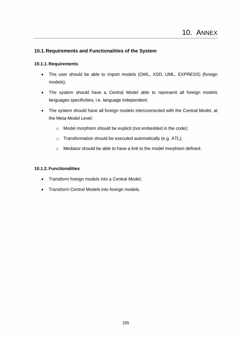
105
10. ANNEX
10.1. Requirements and Functionalities of the System
10.1.1. Requirements
The user should be able to import models (OWL, XSD, UML, EXPRESS) (foreign
models);
The system should have a Central Model able to represent all foreign models
languages specificities, i.e. language independent;
The system should have all foreign models interconnected with the Central Model, at
the Meta-Model Level:
o Model morphism should be explicit (not embedded in the code);
o Transformation should be executed automatically (e.g. ATL);
o Mediator should be able to have a link to the model morphism defined.
10.1.2. Functionalities
Transform foreign models into a Central Model;
Transform Central Models into foreign models.
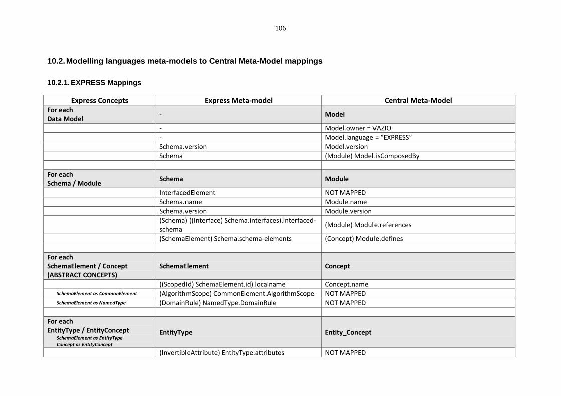
106
10.2. Modelling languages meta-models to Central Meta-Model mappings
10.2.1. EXPRESS Mappings
Express Concepts Express Meta-model Central Meta-Model For each Data Model
- Model
- Model.owner = VAZIO
- Model.language = “EXPRESS”
Schema.version Model.version
Schema (Module) Model.isComposedBy
For each Schema / Module
Schema Module
InterfacedElement NOT MAPPED
Schema.name Module.name
Schema.version Module.version
(Schema) ((Interface) Schema.interfaces).interfaced-schema
(Module) Module.references
(SchemaElement) Schema.schema-elements (Concept) Module.defines
For each SchemaElement / Concept (ABSTRACT CONCEPTS)
SchemaElement Concept
((ScopedId) SchemaElement.id).localname Concept.name SchemaElement as CommonElement (AlgorithmScope) CommonElement.AlgorithmScope NOT MAPPED SchemaElement as NamedType (DomainRule) NamedType.DomainRule NOT MAPPED
For each EntityType / EntityConcept
SchemaElement as EntityType Concept as EntityConcept
EntityType Entity_Concept
(InvertibleAttribute) EntityType.attributes NOT MAPPED
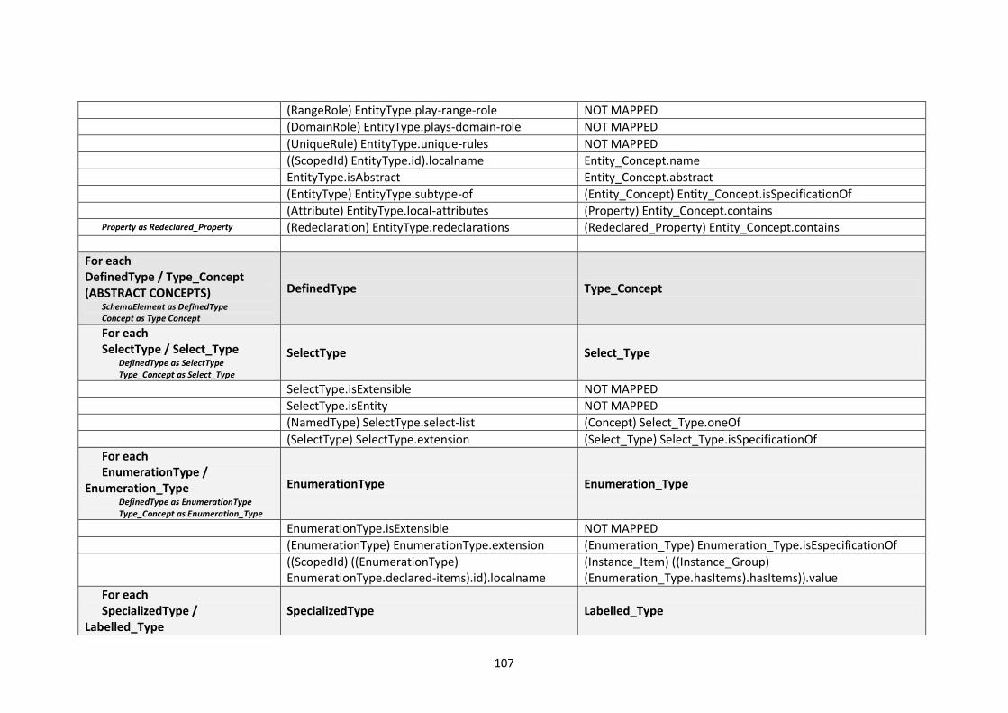
107
(RangeRole) EntityType.play-range-role NOT MAPPED
(DomainRole) EntityType.plays-domain-role NOT MAPPED
(UniqueRule) EntityType.unique-rules NOT MAPPED
((ScopedId) EntityType.id).localname Entity_Concept.name
EntityType.isAbstract Entity_Concept.abstract
(EntityType) EntityType.subtype-of (Entity_Concept) Entity_Concept.isSpecificationOf
(Attribute) EntityType.local-attributes (Property) Entity_Concept.contains Property as Redeclared_Property (Redeclaration) EntityType.redeclarations (Redeclared_Property) Entity_Concept.contains
For each DefinedType / Type_Concept (ABSTRACT CONCEPTS)
SchemaElement as DefinedType Concept as Type Concept
DefinedType Type_Concept
For each SelectType / Select_Type
DefinedType as SelectType Type_Concept as Select_Type
SelectType Select_Type
SelectType.isExtensible NOT MAPPED
SelectType.isEntity NOT MAPPED
(NamedType) SelectType.select-list (Concept) Select_Type.oneOf
(SelectType) SelectType.extension (Select_Type) Select_Type.isSpecificationOf
For each EnumerationType /
Enumeration_Type DefinedType as EnumerationType Type_Concept as Enumeration_Type
EnumerationType Enumeration_Type
EnumerationType.isExtensible NOT MAPPED
(EnumerationType) EnumerationType.extension (Enumeration_Type) Enumeration_Type.isEspecificationOf
((ScopedId) ((EnumerationType) EnumerationType.declared-items).id).localname
(Instance_Item) ((Instance_Group) (Enumeration_Type.hasItems).hasItems)).value
For each SpecializedType /
Labelled_Type SpecializedType Labelled_Type

108
DefinedType as SpecializedType Type_Concept as Labelled_Type
(ConcreteType) SpecializedType.underlying-type (Representation) Labelled_Type.baseType
For each AnonymousType
(AnonymousType) AnonymousType.specializes NOT MAPPED AnonymousType as SimpleType SimpleType Generic_Basic_Type SimpleType.id Generic_Basic_Type.type Specific attributes of sub-types of SimpleType NOT MAPPED
AnonymousType as ConcreteAgregationType ConcreteAggregationType Aggregation_Type
ConcreteAggregationType.ordering NOT MAPPED
ConcreteAggregationType.isUnique NOT MAPPED
(InstantiableType) ConcreteAggregationType.member-type
(Representation) Aggregation_Type.baseType
ConcreteAggregationType as BAGType, LISTType & SETType
((SizeConstraint) (BAGType, LISTType & SETType).lower-bound).bound / “0” (if non-existant)
Aggregation_Type.lowerCardinality
((SizeConstraint) (BAGType, LISTType & SETType).upper-bound).bound / “?” (if non-existant)
Aggregation_Type.upperCardinality
ConcreteAggregationType as ARRAYType ((ArrayBound) ARRAYType.lo-index).bound Aggregation_Type.lowerCardinality
((ArrayBound) ARRAYType.hi-index).bound Aggregation_Type.upperCardinality
For each Attribute / Property
Attribute Property
Attribute.isAbstract NOT MAPPED
Attribute.position NOT MAPPED Attribute as InverseAttribute NOT MAPPED Attribute as InvertibleAttribute NOT MAPPED Attribute as ExplicitAttribute or DerivedAttribute ((ScopedId) Attribute.id).localname Property.name
(InstantiableType)((ParameterType) Attribute.attribute-type)
(Representation) Property.ofType

109
Attribute as ExplicitAttribute Attribute.ExplicitAttribute.isOptional Property.optional
For each Redeclaration / Redefinition
Redeclaration.position NOT MAPPED
Redeclaration.refined-role NOT MAPPED
Redeclaration.derivation NOT MAPPED
Redeclaration.upper-bound NOT MAPPED
Redeclaration.lower-bound NOT MAPPED
Redeclaration.refines (Redeclared_Property) Redeclared_Property.isRefinementOf
(EntityType) Redeclaration.scope (Entity_Concept) Redeclared_Property.fromScope
(Attribute) Redeclaration.original-attribute (Property) Redeclared_Property.originalProperty
(InstantiableType) Redeclaration.restricted-type (Representation) Redefinition.ofType
Redeclaration.isMandatory !Redeclared_Property.optional If Redeclaration.alias exist ((ScopedId) Redeclaration.alias).localname Redeclared_Property.name
Else ((ScopedId) Redeclaration.originalAttribute.id).localname
Redeclared_Property.name
10.2.2. XML Schema (XSD) Mappings
Express Concepts XSD Meta-model Central Meta-Model For each Data Model (xsd)
- Model
- Model.owner = VAZIO
- Model.language = “XSD”
schema.version Model.version
schema (Module) Model.isComposedBy
For each schema / Module
schema Module
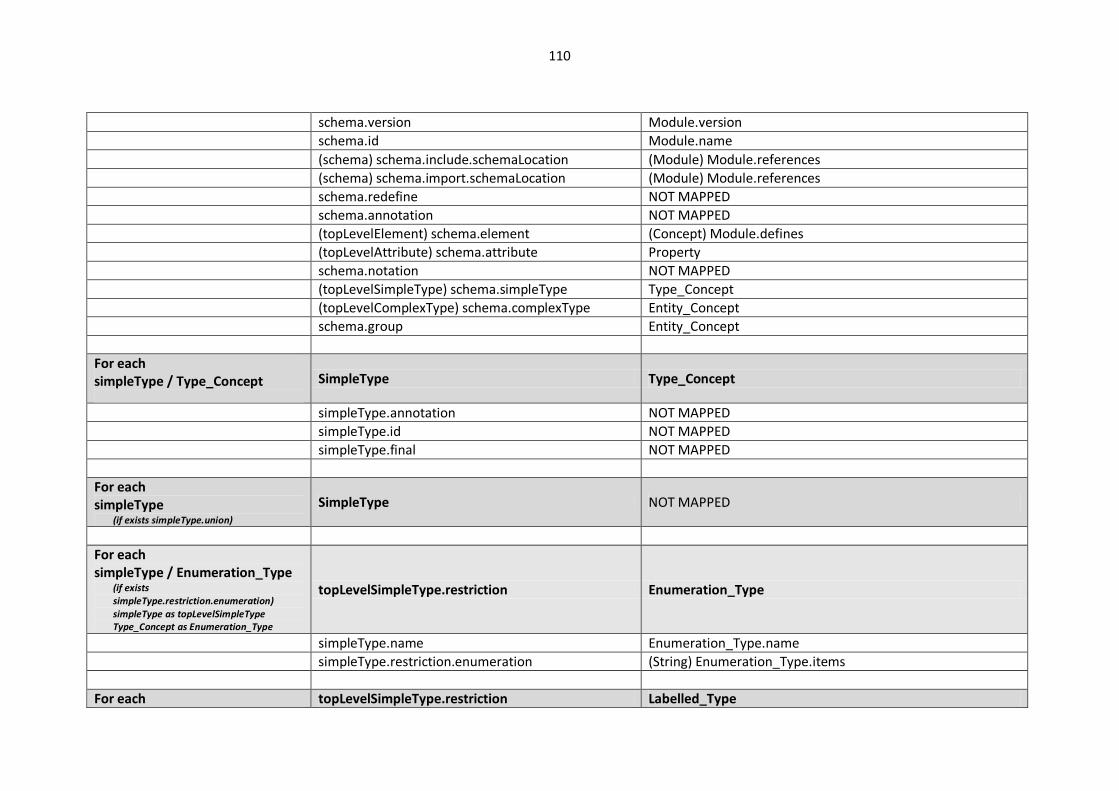
110
schema.version Module.version
schema.id Module.name
(schema) schema.include.schemaLocation (Module) Module.references
(schema) schema.import.schemaLocation (Module) Module.references
schema.redefine NOT MAPPED
schema.annotation NOT MAPPED
(topLevelElement) schema.element (Concept) Module.defines
(topLevelAttribute) schema.attribute Property
schema.notation NOT MAPPED
(topLevelSimpleType) schema.simpleType Type_Concept
(topLevelComplexType) schema.complexType Entity_Concept
schema.group Entity_Concept
For each simpleType / Type_Concept
SimpleType Type_Concept
simpleType.annotation NOT MAPPED simpleType.id NOT MAPPED simpleType.final NOT MAPPED
For each simpleType
(if exists simpleType.union)
SimpleType NOT MAPPED
For each simpleType / Enumeration_Type
(if exists simpleType.restriction.enumeration) simpleType as topLevelSimpleType Type_Concept as Enumeration_Type
topLevelSimpleType.restriction Enumeration_Type
simpleType.name Enumeration_Type.name
simpleType.restriction.enumeration (String) Enumeration_Type.items
For each topLevelSimpleType.restriction Labelled_Type
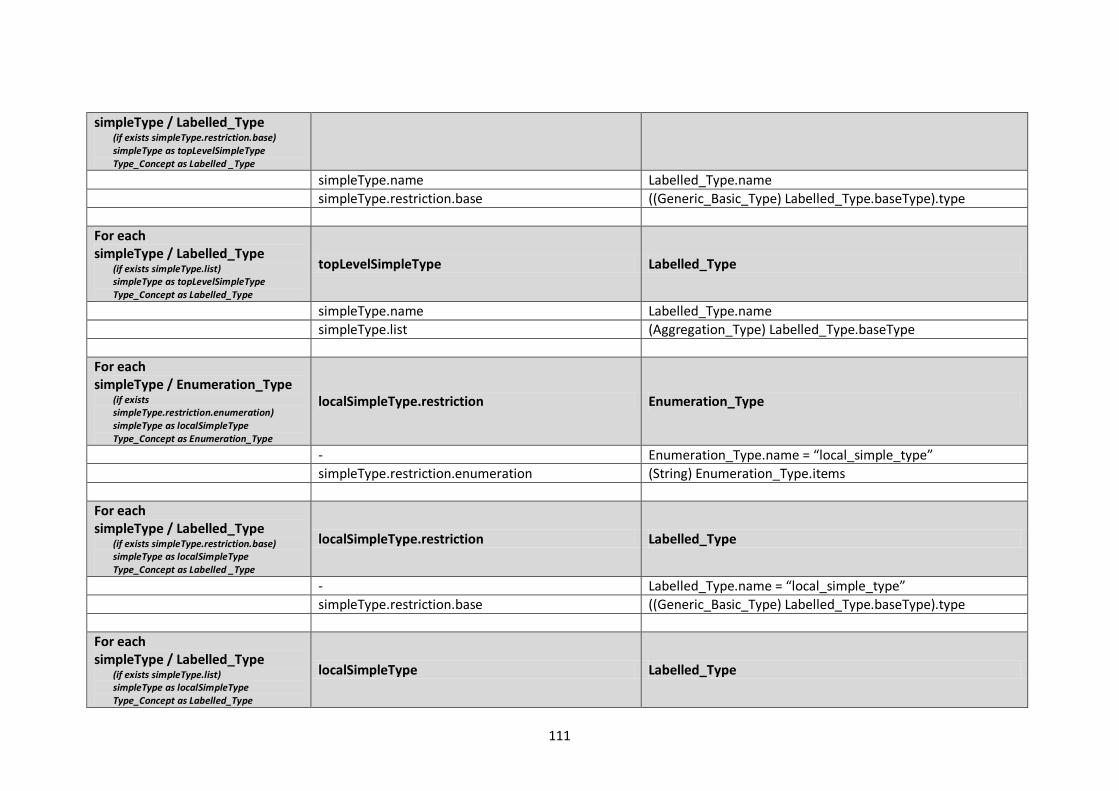
111
simpleType / Labelled_Type (if exists simpleType.restriction.base) simpleType as topLevelSimpleType Type_Concept as Labelled _Type
simpleType.name Labelled_Type.name
simpleType.restriction.base ((Generic_Basic_Type) Labelled_Type.baseType).type
For each simpleType / Labelled_Type
(if exists simpleType.list) simpleType as topLevelSimpleType Type_Concept as Labelled_Type
topLevelSimpleType Labelled_Type
simpleType.name Labelled_Type.name
simpleType.list (Aggregation_Type) Labelled_Type.baseType
For each simpleType / Enumeration_Type
(if exists simpleType.restriction.enumeration) simpleType as localSimpleType Type_Concept as Enumeration_Type
localSimpleType.restriction Enumeration_Type
- Enumeration_Type.name = “local_simple_type”
simpleType.restriction.enumeration (String) Enumeration_Type.items
For each simpleType / Labelled_Type
(if exists simpleType.restriction.base) simpleType as localSimpleType Type_Concept as Labelled _Type
localSimpleType.restriction Labelled_Type
- Labelled_Type.name = “local_simple_type”
simpleType.restriction.base ((Generic_Basic_Type) Labelled_Type.baseType).type
For each simpleType / Labelled_Type
(if exists simpleType.list) simpleType as localSimpleType Type_Concept as Labelled_Type
localSimpleType Labelled_Type
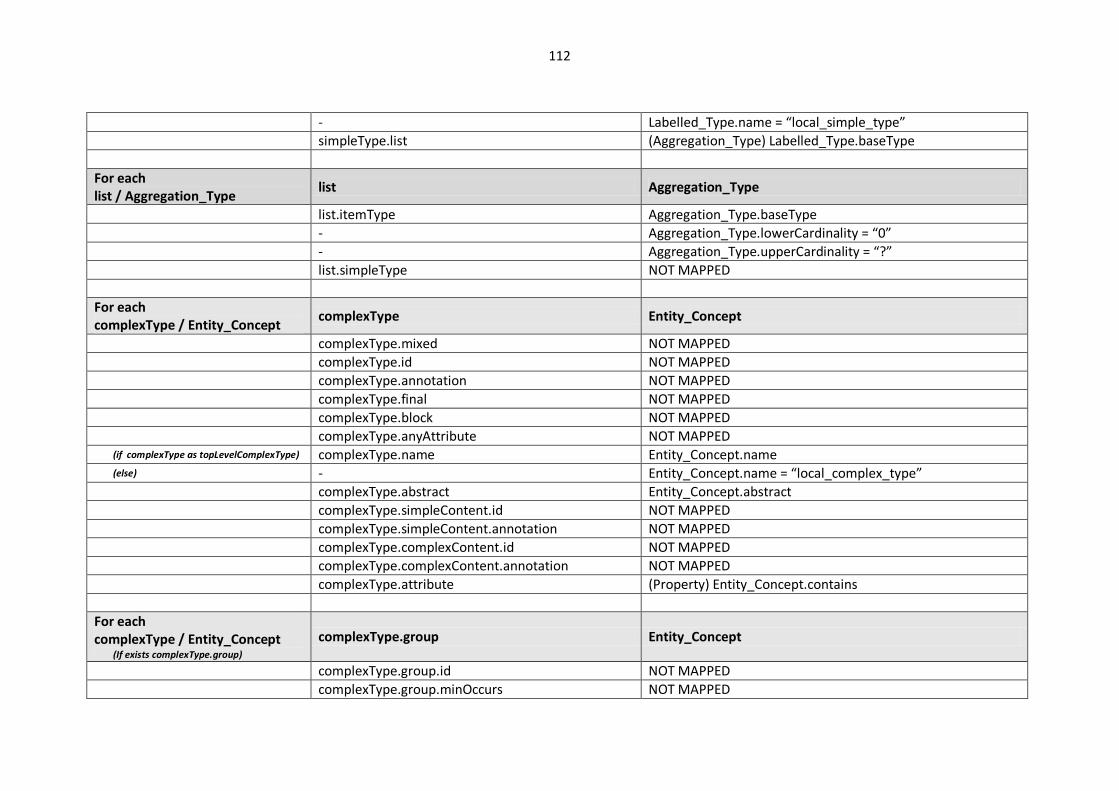
112
- Labelled_Type.name = “local_simple_type”
simpleType.list (Aggregation_Type) Labelled_Type.baseType
For each list / Aggregation_Type
list Aggregation_Type
list.itemType Aggregation_Type.baseType
- Aggregation_Type.lowerCardinality = “0”
- Aggregation_Type.upperCardinality = “?”
list.simpleType NOT MAPPED
For each complexType / Entity_Concept
complexType Entity_Concept
complexType.mixed NOT MAPPED
complexType.id NOT MAPPED
complexType.annotation NOT MAPPED
complexType.final NOT MAPPED
complexType.block NOT MAPPED
complexType.anyAttribute NOT MAPPED (if complexType as topLevelComplexType) complexType.name Entity_Concept.name (else) - Entity_Concept.name = “local_complex_type”
complexType.abstract Entity_Concept.abstract
complexType.simpleContent.id NOT MAPPED
complexType.simpleContent.annotation NOT MAPPED
complexType.complexContent.id NOT MAPPED
complexType.complexContent.annotation NOT MAPPED
complexType.attribute (Property) Entity_Concept.contains
For each complexType / Entity_Concept
(If exists complexType.group)
complexType.group Entity_Concept
complexType.group.id NOT MAPPED
complexType.group.minOccurs NOT MAPPED
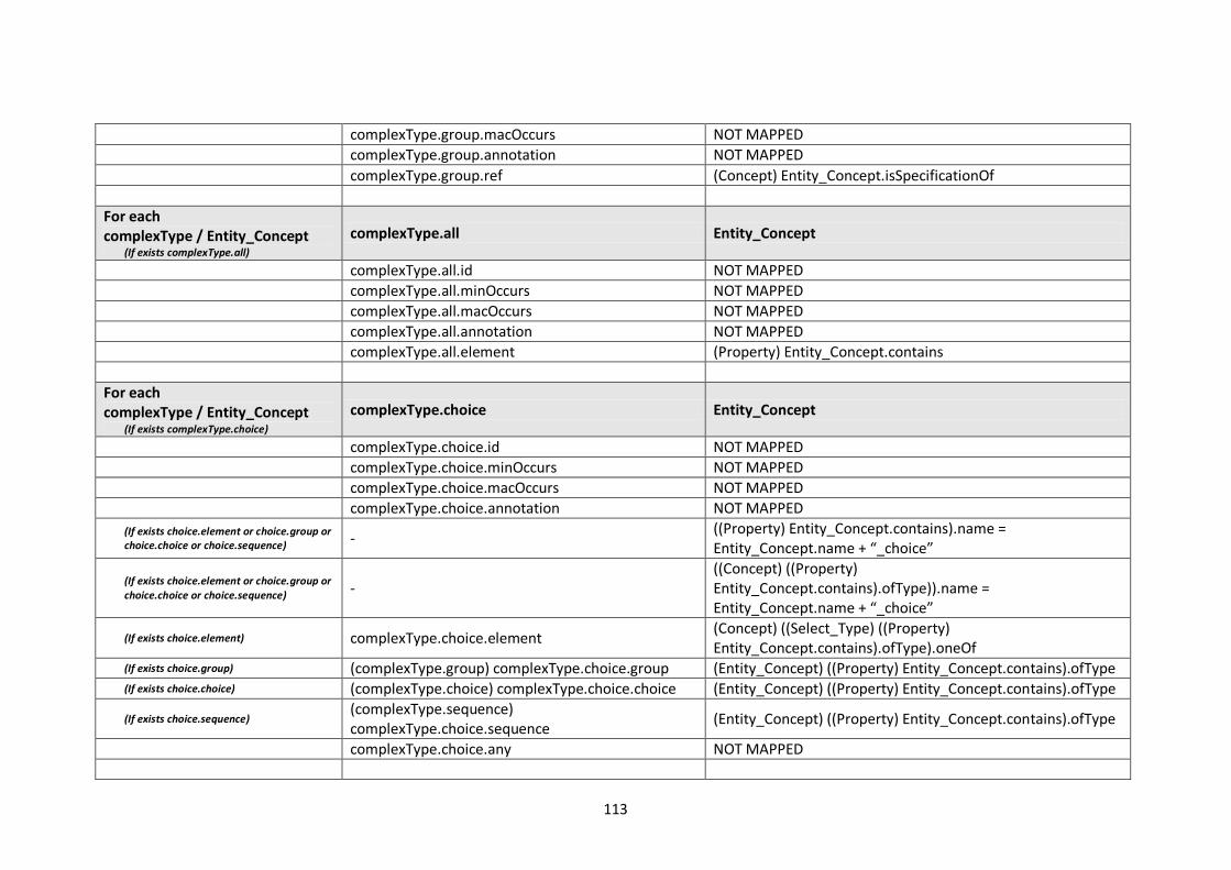
113
complexType.group.macOccurs NOT MAPPED
complexType.group.annotation NOT MAPPED
complexType.group.ref (Concept) Entity_Concept.isSpecificationOf
For each complexType / Entity_Concept
(If exists complexType.all)
complexType.all Entity_Concept
complexType.all.id NOT MAPPED
complexType.all.minOccurs NOT MAPPED
complexType.all.macOccurs NOT MAPPED
complexType.all.annotation NOT MAPPED
complexType.all.element (Property) Entity_Concept.contains
For each complexType / Entity_Concept
(If exists complexType.choice)
complexType.choice Entity_Concept
complexType.choice.id NOT MAPPED
complexType.choice.minOccurs NOT MAPPED
complexType.choice.macOccurs NOT MAPPED
complexType.choice.annotation NOT MAPPED
(If exists choice.element or choice.group or choice.choice or choice.sequence) -
((Property) Entity_Concept.contains).name = Entity_Concept.name + “_choice”
(If exists choice.element or choice.group or choice.choice or choice.sequence) -
((Concept) ((Property) Entity_Concept.contains).ofType)).name = Entity_Concept.name + “_choice”
(If exists choice.element) complexType.choice.element (Concept) ((Select_Type) ((Property) Entity_Concept.contains).ofType).oneOf
(If exists choice.group) (complexType.group) complexType.choice.group (Entity_Concept) ((Property) Entity_Concept.contains).ofType (If exists choice.choice) (complexType.choice) complexType.choice.choice (Entity_Concept) ((Property) Entity_Concept.contains).ofType
(If exists choice.sequence) (complexType.sequence) complexType.choice.sequence
(Entity_Concept) ((Property) Entity_Concept.contains).ofType
complexType.choice.any NOT MAPPED
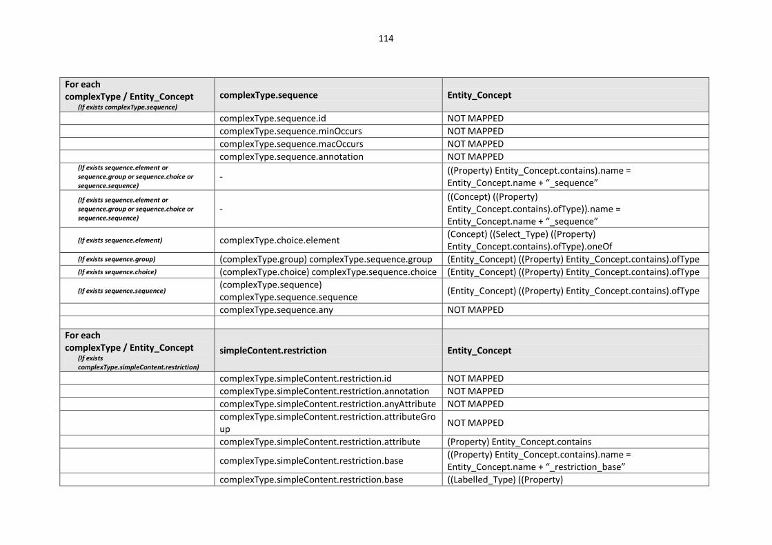
114
For each complexType / Entity_Concept
(If exists complexType.sequence)
complexType.sequence Entity_Concept
complexType.sequence.id NOT MAPPED
complexType.sequence.minOccurs NOT MAPPED
complexType.sequence.macOccurs NOT MAPPED
complexType.sequence.annotation NOT MAPPED (If exists sequence.element or sequence.group or sequence.choice or sequence.sequence)
- ((Property) Entity_Concept.contains).name = Entity_Concept.name + “_sequence”
(If exists sequence.element or sequence.group or sequence.choice or sequence.sequence)
- ((Concept) ((Property) Entity_Concept.contains).ofType)).name = Entity_Concept.name + “_sequence”
(If exists sequence.element) complexType.choice.element (Concept) ((Select_Type) ((Property) Entity_Concept.contains).ofType).oneOf
(If exists sequence.group) (complexType.group) complexType.sequence.group (Entity_Concept) ((Property) Entity_Concept.contains).ofType (If exists sequence.choice) (complexType.choice) complexType.sequence.choice (Entity_Concept) ((Property) Entity_Concept.contains).ofType
(If exists sequence.sequence) (complexType.sequence) complexType.sequence.sequence
(Entity_Concept) ((Property) Entity_Concept.contains).ofType
complexType.sequence.any NOT MAPPED
For each complexType / Entity_Concept
(If exists complexType.simpleContent.restriction)
simpleContent.restriction Entity_Concept
complexType.simpleContent.restriction.id NOT MAPPED
complexType.simpleContent.restriction.annotation NOT MAPPED
complexType.simpleContent.restriction.anyAttribute NOT MAPPED
complexType.simpleContent.restriction.attributeGroup
NOT MAPPED
complexType.simpleContent.restriction.attribute (Property) Entity_Concept.contains
complexType.simpleContent.restriction.base ((Property) Entity_Concept.contains).name = Entity_Concept.name + “_restriction_base”
complexType.simpleContent.restriction.base ((Labelled_Type) ((Property)
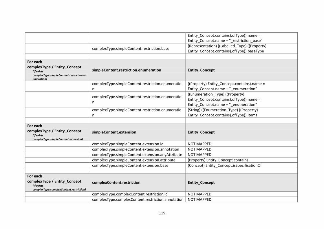
115
Entity_Concept.contains).ofType)).name = Entity_Concept.name + “_restriction_base”
complexType.simpleContent.restriction.base (Representation) ((Labelled_Type) ((Property) Entity_Concept.contains).ofType)).baseType
For each complexType / Entity_Concept
(If exists complexType.simpleContent.restriction.enumeration)
simpleContent.restriction.enumeration Entity_Concept
complexType.simpleContent.restriction.enumeration
((Property) Entity_Concept.contains).name = Entity_Concept.name + “_enumeration”
complexType.simpleContent.restriction.enumeration
((Enumeration_Type) ((Property) Entity_Concept.contains).ofType)).name = Entity_Concept.name + “_enumeration”
complexType.simpleContent.restriction.enumeration
(String) ((Enumeration_Type) ((Property) Entity_Concept.contains).ofType)).items
For each complexType / Entity_Concept
(If exists complexType.simpleContent.extension)
simpleContent.extension Entity_Concept
complexType.simpleContent.extension.id NOT MAPPED
complexType.simpleContent.extension.annotation NOT MAPPED
complexType.simpleContent.extension.anyAttribute NOT MAPPED
complexType.simpleContent.extension.attribute (Property) Entity_Concept.contains
complexType.simpleContent.extension.base (Concept) Entity_Concept.isSpecificationOf
For each complexType / Entity_Concept
(If exists complexType.complexContent.restriction)
complexContent.restriction Entity_Concept
complexType.complexContent.restriction.id NOT MAPPED
complexType.complexContent.restriction.annotation NOT MAPPED
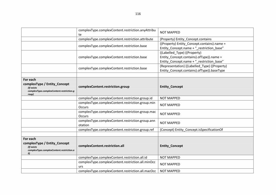
116
complexType.complexContent.restriction.anyAttribute
NOT MAPPED
complexType.complexContent.restriction.attribute (Property) Entity_Concept.contains
complexType.complexContent.restriction.base ((Property) Entity_Concept.contains).name = Entity_Concept.name + “_restriction_base”
complexType.complexContent.restriction.base ((Labelled_Type) ((Property) Entity_Concept.contains).ofType)).name = Entity_Concept.name + “_restriction_base”
complexType.complexContent.restriction.base (Representation) ((Labelled_Type) ((Property) Entity_Concept.contains).ofType)).baseType
For each complexType / Entity_Concept
(If exists complexType.complexContent.restriction.group)
complexContent.restriction.group Entity_Concept
complexType.complexContent.restriction.group.id NOT MAPPED
complexType.complexContent.restriction.group.minOccurs
NOT MAPPED
complexType.complexContent.restriction.group.macOccurs
NOT MAPPED
complexType.complexContent.restriction.group.annotation
NOT MAPPED
complexType.complexContent.restriction.group.ref (Concept) Entity_Concept.isSpecificationOf
For each complexType / Entity_Concept
(If exists complexType.complexContent.restriction.all)
complexContent.restriction.all Entity_Concept
complexType.complexContent.restriction.all.id NOT MAPPED
complexType.complexContent.restriction.all.minOccurs
NOT MAPPED
complexType.complexContent.restriction.all.macOcc NOT MAPPED

117
urs
complexType.complexContent.restriction.all.annotation
NOT MAPPED
complexType.complexContent.restriction.all.element
(Property) Entity_Concept.contains
For each complexType / Entity_Concept
(If exists complexType.complexContent.restriction.choice)
complexContent.restriction.choice Entity_Concept
complexType.complexContent.restriction.choice.id NOT MAPPED
complexType.complexContent.restriction.choice.minOccurs
NOT MAPPED
complexType.complexContent.restriction.choice.macOccurs
NOT MAPPED
complexType.complexContent.restriction.choice.annotation
NOT MAPPED
(If exists choice.element or choice.group or choice.choice or choice.sequence) -
((Property) Entity_Concept.contains).name = Entity_Concept.name + “_restriction_choice”
(If exists choice.element or choice.group or choice.choice or choice.sequence) -
((Concept) ((Property) Entity_Concept.contains).ofType)).name = Entity_Concept.name + “_restriction_choice”
(If exists choice.element) complexType.complexContent.restriction.choice.element
(Concept) ((Select_Type) ((Property) Entity_Concept.contains).ofType).oneOf
(If exists choice.group) (complexContent.restriction.group) complexType.complexContent.restriction.choice.group
(Entity_Concept) ((Property) Entity_Concept.contains).ofType
(If exists choice.choice) (complexContent.restriction.choice) complexType.complexContent.restriction.choice.choice
(Entity_Concept) ((Property) Entity_Concept.contains).ofType
(If exists choice.sequence) (complexContent.restriction.sequence) complexType.complexContent.restriction.choice.seq
(Entity_Concept) ((Property) Entity_Concept.contains).ofType

118
uence
complexType.complexContent.restriction.choice.any NOT MAPPED
For each complexType / Entity_Concept
(If exists complexType.complexContent.restriction.sequence)
complexContent.restriction.sequence Entity_Concept
complexType.complexContent.restriction.sequence.id
NOT MAPPED
complexType.complexContent.restriction.sequence.minOccurs
NOT MAPPED
complexType.complexContent.restriction.sequence.macOccurs
NOT MAPPED
complexType.complexContent.restriction.sequence.annotation
NOT MAPPED
(If exists sequence.element or sequence.group or sequence.choice or sequence.sequence)
- ((Property) Entity_Concept.contains).name = Entity_Concept.name + “_restriction_sequence”
(If exists sequence.element or sequence.group or sequence.choice or sequence.sequence)
- ((Concept) ((Property) Entity_Concept.contains).ofType)).name = Entity_Concept.name + “_restriction_sequence”
(If exists sequence.element) complexType.complexContent.restriction.sequence.element
(Concept) ((Select_Type) ((Property) Entity_Concept.contains).ofType).oneOf
(If exists sequence.group) (complexContent.restriction.group) complexType.complexContent.restriction.sequence.group
(Entity_Concept) ((Property) Entity_Concept.contains).ofType
(If exists sequence.choice) (complexContent.restriction.choice) complexType.complexContent.restriction.sequence.choice
(Entity_Concept) ((Property) Entity_Concept.contains).ofType
(If exists sequence.sequence) (complexContent.restriction.sequence) complexType.complexContent.restriction.sequence.sequence
(Entity_Concept) ((Property) Entity_Concept.contains).ofType
complexType.complexContent.restriction.sequence. NOT MAPPED

119
any
For each complexType / Entity_Concept
(If exists complexType.complexContent.extension)
complexContent.extension Entity_Concept
complexType.complexContent.extension.id NOT MAPPED
complexType.complexContent.extension.annotation NOT MAPPED
complexType.complexContent.extension.anyAttribute
NOT MAPPED
complexType.complexContent.extension.attribute (Property) Entity_Concept.contains
complexType.complexContent.extension.base (Concept) Entity_Concept.isSpecificationOf
For each complexType / Entity_Concept
(If exists complexType.complexContent.extension.group)
complexContent.extension.group Entity_Concept
complexType.complexContent.extension.group.id NOT MAPPED
complexType.complexContent.extension.group.minOccurs
NOT MAPPED
complexType.complexContent.extension.group.macOccurs
NOT MAPPED
complexType.complexContent.extension.group.annotation
NOT MAPPED
complexType.complexContent.extension.group.ref (Concept) Entity_Concept.isSpecificationOf
For each complexType / Entity_Concept
(If exists complexType.complexContent.extension.all)
complexContent.extension.all Entity_Concept
complexType.complexContent.extension.all.id NOT MAPPED
complexType.complexContent.extension.all.minOccurs
NOT MAPPED
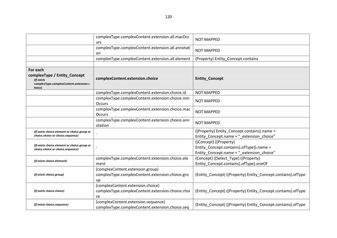
120
complexType.complexContent.extension.all.macOccurs
NOT MAPPED
complexType.complexContent.extension.all.annotation
NOT MAPPED
complexType.complexContent.extension.all.element (Property) Entity_Concept.contains
For each complexType / Entity_Concept
(If exists complexType.complexContent.extension.choice)
complexContent.extension.choice Entity_Concept
complexType.complexContent.extension.choice.id NOT MAPPED
complexType.complexContent.extension.choice.minOccurs
NOT MAPPED
complexType.complexContent.extension.choice.macOccurs
NOT MAPPED
complexType.complexContent.extension.choice.annotation
NOT MAPPED
(If exists choice.element or choice.group or choice.choice or choice.sequence) -
((Property) Entity_Concept.contains).name = Entity_Concept.name + “_extension_choice”
(If exists choice.element or choice.group or choice.choice or choice.sequence) -
((Concept) ((Property) Entity_Concept.contains).ofType)).name = Entity_Concept.name + “_extension_choice”
(If exists choice.element) complexType.complexContent.extension.choice.element
(Concept) ((Select_Type) ((Property) Entity_Concept.contains).ofType).oneOf
(If exists choice.group) (complexContent.extension.group) complexType.complexContent.extension.choice.group
(Entity_Concept) ((Property) Entity_Concept.contains).ofType
(If exists choice.choice) (complexContent.extension.choice) complexType.complexContent.extension.choice.choice
(Entity_Concept) ((Property) Entity_Concept.contains).ofType
(If exists choice.sequence) (complexContent.extension.sequence) complexType.complexContent.extension.choice.seq
(Entity_Concept) ((Property) Entity_Concept.contains).ofType
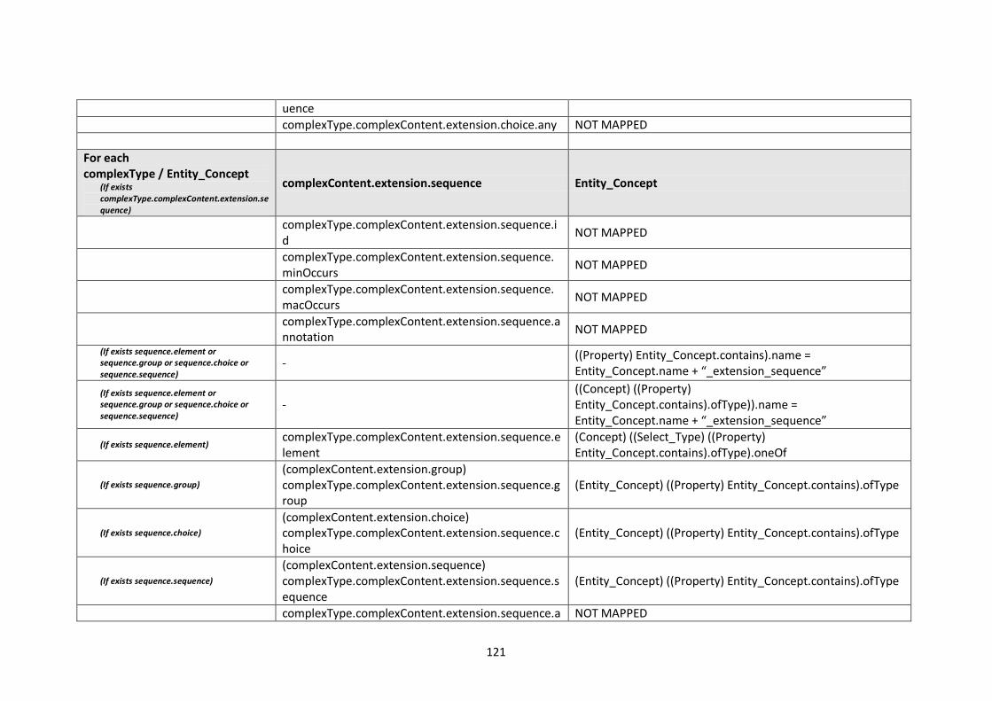
121
uence
complexType.complexContent.extension.choice.any NOT MAPPED
For each complexType / Entity_Concept
(If exists complexType.complexContent.extension.sequence)
complexContent.extension.sequence Entity_Concept
complexType.complexContent.extension.sequence.id
NOT MAPPED
complexType.complexContent.extension.sequence.minOccurs
NOT MAPPED
complexType.complexContent.extension.sequence.macOccurs
NOT MAPPED
complexType.complexContent.extension.sequence.annotation
NOT MAPPED
(If exists sequence.element or sequence.group or sequence.choice or sequence.sequence)
- ((Property) Entity_Concept.contains).name = Entity_Concept.name + “_extension_sequence”
(If exists sequence.element or sequence.group or sequence.choice or sequence.sequence)
- ((Concept) ((Property) Entity_Concept.contains).ofType)).name = Entity_Concept.name + “_extension_sequence”
(If exists sequence.element) complexType.complexContent.extension.sequence.element
(Concept) ((Select_Type) ((Property) Entity_Concept.contains).ofType).oneOf
(If exists sequence.group) (complexContent.extension.group) complexType.complexContent.extension.sequence.group
(Entity_Concept) ((Property) Entity_Concept.contains).ofType
(If exists sequence.choice) (complexContent.extension.choice) complexType.complexContent.extension.sequence.choice
(Entity_Concept) ((Property) Entity_Concept.contains).ofType
(If exists sequence.sequence) (complexContent.extension.sequence) complexType.complexContent.extension.sequence.sequence
(Entity_Concept) ((Property) Entity_Concept.contains).ofType
complexType.complexContent.extension.sequence.a NOT MAPPED

122
ny
For each group / Entity_Concept
group Entity_Concept
group.id NOT MAPPED
group.annotation NOT MAPPED
group.name Entity_Concept.name
For each group / Entity_Concept
(If exists group.all)
group.all Entity_Concept
group.all.id NOT MAPPED
group.all.annotation NOT MAPPED
group.all.element (Property) Entity_Concept.contains
For each group / Entity_Concept
(If exists group.choice)
group.choice Entity_Concept
group.choice.id NOT MAPPED
group.choice.annotation NOT MAPPED
(If exists choice.element or choice.group or choice.choice or choice.sequence) -
((Property) Entity_Concept.contains).name = Entity_Concept.name + “_group_choice”
(If exists choice.element or choice.group or choice.choice or choice.sequence) -
((Concept) ((Property) Entity_Concept.contains).ofType)).name = Entity_Concept.name + “_group_choice”
(If exists choice.element) group.choice.element (Concept) ((Select_Type) ((Property) Entity_Concept.contains).ofType).oneOf
(If exists choice.group) (group) group.choice.group (Entity_Concept) ((Property) Entity_Concept.contains).ofType (If exists choice.choice) (group.choice) group.choice.choice (Entity_Concept) ((Property) Entity_Concept.contains).ofType (If exists choice.sequence) (group.sequence) group.choice.sequence (Entity_Concept) ((Property) Entity_Concept.contains).ofType
group.choice.any NOT MAPPED
For each group.sequence Entity_Concept
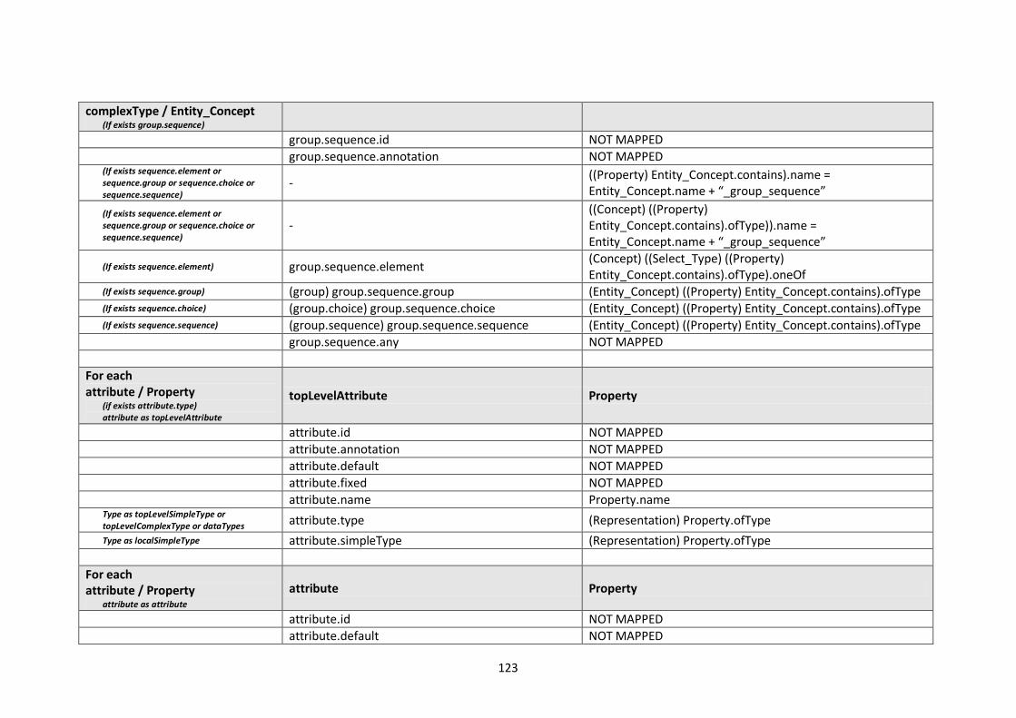
123
complexType / Entity_Concept (If exists group.sequence)
group.sequence.id NOT MAPPED
group.sequence.annotation NOT MAPPED (If exists sequence.element or sequence.group or sequence.choice or sequence.sequence)
- ((Property) Entity_Concept.contains).name = Entity_Concept.name + “_group_sequence”
(If exists sequence.element or sequence.group or sequence.choice or sequence.sequence)
- ((Concept) ((Property) Entity_Concept.contains).ofType)).name = Entity_Concept.name + “_group_sequence”
(If exists sequence.element) group.sequence.element (Concept) ((Select_Type) ((Property) Entity_Concept.contains).ofType).oneOf
(If exists sequence.group) (group) group.sequence.group (Entity_Concept) ((Property) Entity_Concept.contains).ofType (If exists sequence.choice) (group.choice) group.sequence.choice (Entity_Concept) ((Property) Entity_Concept.contains).ofType (If exists sequence.sequence) (group.sequence) group.sequence.sequence (Entity_Concept) ((Property) Entity_Concept.contains).ofType
group.sequence.any NOT MAPPED
For each attribute / Property
(if exists attribute.type) attribute as topLevelAttribute
topLevelAttribute Property
attribute.id NOT MAPPED
attribute.annotation NOT MAPPED
attribute.default NOT MAPPED
attribute.fixed NOT MAPPED
attribute.name Property.name Type as topLevelSimpleType or topLevelComplexType or dataTypes attribute.type (Representation) Property.ofType
Type as localSimpleType attribute.simpleType (Representation) Property.ofType
For each attribute / Property
attribute as attribute attribute Property
attribute.id NOT MAPPED
attribute.default NOT MAPPED

124
attribute.fixed NOT MAPPED
attribute.annotation NOT MAPPED (if exists attribute.name) attribute.name Property.name (else) attribute.ref Property
attribute.use == “optional” Property.optional = true
attribute.use == “required” Property.optional = false
attribute.use == “prohibited” NOT MAPPED (if exists attribute.name and attribute.type) Type as topLevelSimpleType or topLevelComplexType or dataTypes
attribute.type (Representation) Property.ofType
(else if exists attribute.name) Type as localSimpleType attribute.simpleType (Representation) Property.ofType
For each attributeGroup / NOT MAPPED
attributeGroup NOT MAPPED
For each element / Concept
element Concept
element.annotation NOT MAPPED
element.identifyConstraint NOT MAPPED
element.id NOT MAPPED
element.ref (Concept) Concept.isSpecificationOf
element.default NOT MAPPED
element.fixed NOT MAPPED
element.nillable NOT MAPPED
element.final NOT MAPPED
element.block NOT MAPPED
element.form NOT MAPPED
element.substitutionGroup NOT MAPPED
element.identifyConstraint NOT MAPPED
For each topLevelElement Labelled_Type
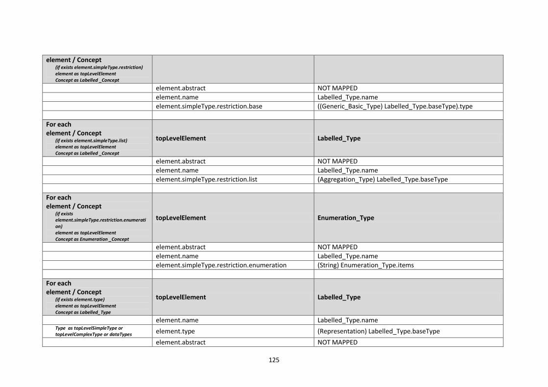
125
element / Concept (if exists element.simpleType.restriction) element as topLevelElement Concept as Labelled _Concept
element.abstract NOT MAPPED
element.name Labelled_Type.name
element.simpleType.restriction.base ((Generic_Basic_Type) Labelled_Type.baseType).type
For each element / Concept
(if exists element.simpleType.list) element as topLevelElement Concept as Labelled _Concept
topLevelElement Labelled_Type
element.abstract NOT MAPPED
element.name Labelled_Type.name
element.simpleType.restriction.list (Aggregation_Type) Labelled_Type.baseType
For each element / Concept
(if exists element.simpleType.restriction.enumeration) element as topLevelElement Concept as Enumeration _Concept
topLevelElement Enumeration_Type
element.abstract NOT MAPPED
element.name Labelled_Type.name
element.simpleType.restriction.enumeration (String) Enumeration_Type.items
For each element / Concept
(if exists element.type) element as topLevelElement Concept as Labelled_Type
topLevelElement Labelled_Type
element.name Labelled_Type.name Type as topLevelSimpleType or topLevelComplexType or dataTypes element.type (Representation) Labelled_Type.baseType
element.abstract NOT MAPPED
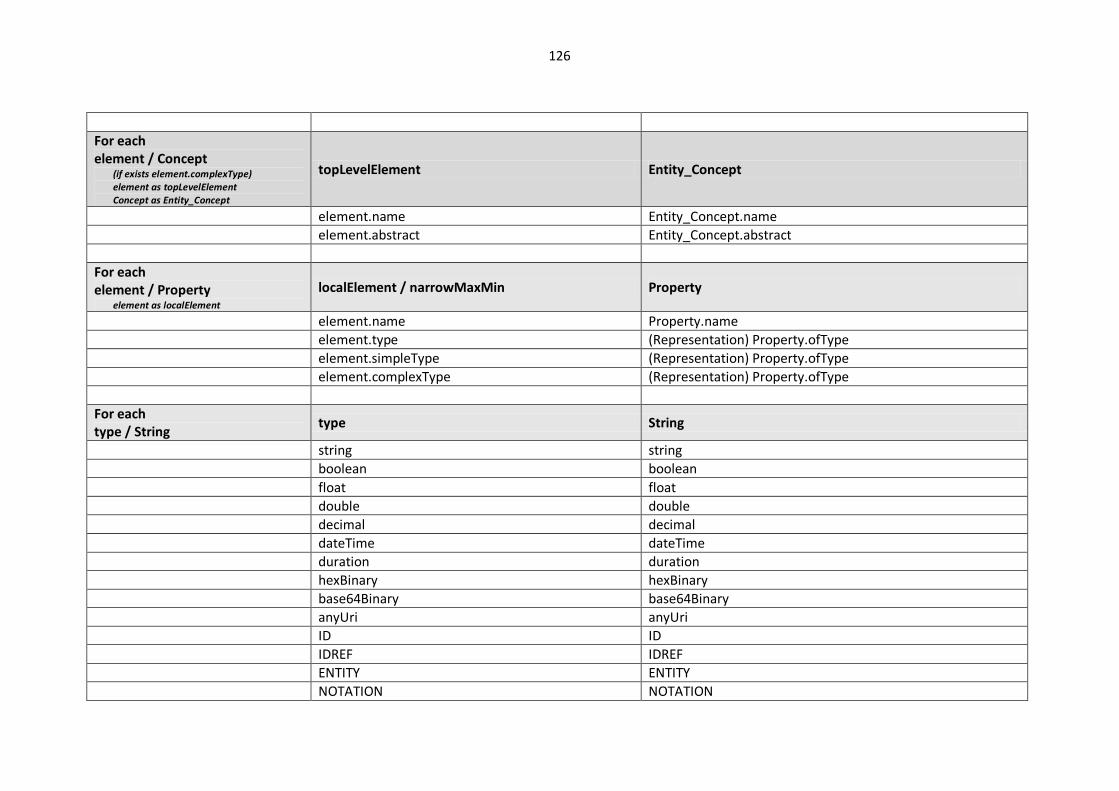
126
For each element / Concept
(if exists element.complexType) element as topLevelElement Concept as Entity_Concept
topLevelElement Entity_Concept
element.name Entity_Concept.name
element.abstract Entity_Concept.abstract
For each element / Property
element as localElement
localElement / narrowMaxMin Property
element.name Property.name
element.type (Representation) Property.ofType
element.simpleType (Representation) Property.ofType
element.complexType (Representation) Property.ofType
For each type / String
type String
string string
boolean boolean
float float
double double
decimal decimal
dateTime dateTime
duration duration
hexBinary hexBinary
base64Binary base64Binary
anyUri anyUri
ID ID
IDREF IDREF
ENTITY ENTITY
NOTATION NOTATION
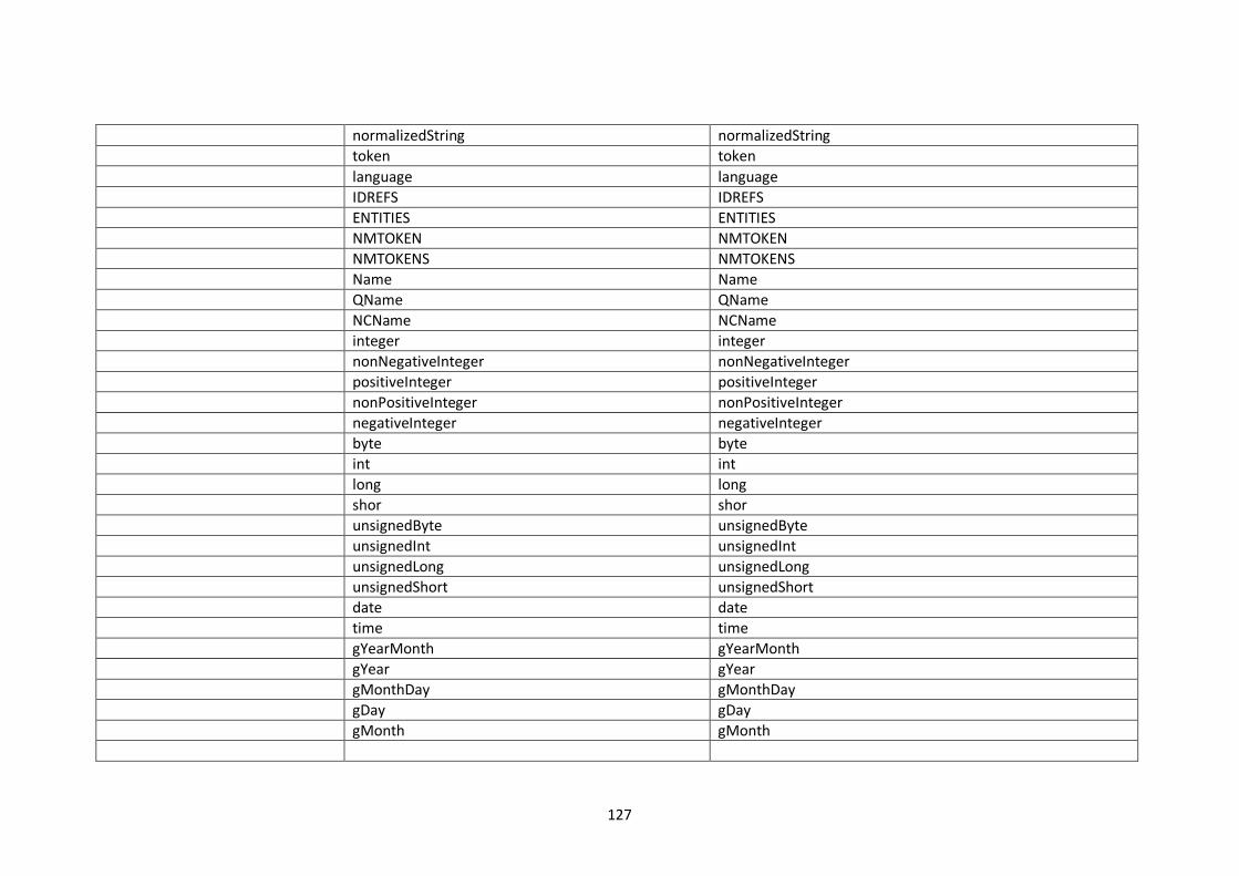
127
normalizedString normalizedString
token token
language language
IDREFS IDREFS
ENTITIES ENTITIES
NMTOKEN NMTOKEN
NMTOKENS NMTOKENS
Name Name
QName QName
NCName NCName
integer integer
nonNegativeInteger nonNegativeInteger
positiveInteger positiveInteger
nonPositiveInteger nonPositiveInteger
negativeInteger negativeInteger
byte byte
int int
long long
shor shor
unsignedByte unsignedByte
unsignedInt unsignedInt
unsignedLong unsignedLong
unsignedShort unsignedShort
date date
time time
gYearMonth gYearMonth
gYear gYear
gMonthDay gMonthDay
gDay gDay
gMonth gMonth


![Computação Confiável com Quantum-Dot Cellular Automata (QCA)Sill_NaCoWo2015.pdf · Somador completo (FA) em uma camada (adaptado de [10]). Estrutura somadora disposta em uma única](https://img.pdfslide.us/doc/110x75/5c5eb70409d3f2ca1f8cb0a5/computacao-confiavel-com-quantum-dot-cellular-automata-qca-sillnacowo2015pdf.jpg)