Embed Size (px)
Citation preview
All specifications are subject to change without notice
Mini Dot Impact PrinterMODEL : LK-D30

2
1. Features 3
2. Specification 4
3. Self Test 6
4. User Switches 7
5. Command List 8
5.1. EMULATION EPSON TM-U200 8
5.2. EMULATION CITIZEN iDP-3540 9
5.3. EMULATION STAR SP200 10
6. Interface 11
6.1. Interface Connector 11
7. Cash Drawer Connector 13
8. Electrical Specifications 14
9. Dip Switch Settings 15
Table of Contents

3
♣Dip Switch ConfigurationEmulation mode, communications mode, baud rate, serial/parallel handshake, and head printing characteristics are all configured through dip switch settings.
♣Data BufferThe LK-D30 printer has a built-in 16 Kilobyte I/O buffer allowing the host computer to free itself after
sending the print data.♣Reliable communicationsThe LK-D30 supports multiple baud rates, protocols, and handshaking on its parallel & serial
interfaces.
♣User controls
A power switch, a paper feed switch, power LED and Paper Low/Out error LED provide ease of use.
♣Self Test ModeA comprehensive self-test mode is available which describes the printer configuration and dip switch
setting information along with the version number of firmware installed.
♣Print orientationThe printer is capable of printing normal and upside down, the print orientation is selected by software
commands.
♣Selectable international characters
The LK-D30 supports international characters selectable by software control.
♣Multiple Fonts/SizesTwo different resident fonts are available for printing diversity. Each of these fonts can be printed in
normal, double wide, double height, and quadruple sizes. Both fonts and sizes are software selected.
♣Bit image graphic
Two formats for bit mapped graphics are provided.
♣Error detectionThe LK-D30 can detect paper-out and paper-jam as well as paper near-end, controller malfunction, and
cover open status.
♣Peripheral Drive
Two cash drawer drivers are provided.
♣Certification(1) This device complies with Part 15 of the FCC Rules. Operation is subject to the following two conditions: 1) this device may not cause harmful interference , and 2) this device must accept any interference received , including interference that may cause undesired operation.(2) UL/cUL (UL 60950-1)(3) MIC(4) CE-EMCD (CE-EMCD Class B should use Parallel shield Cable complied with IEEE-1284 standards)(5) RoHS (TUV)
1. Features
4
MODEL LK-D30
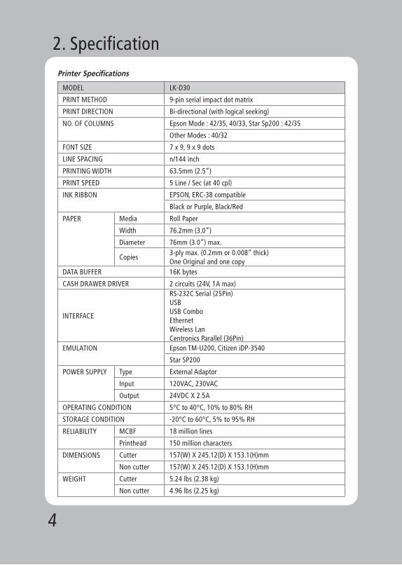
PRINT METHOD 9-pin serial impact dot matrix
PRINT DIRECTION Bi-directional (with logical seeking)
NO. OF COLUMNS Epson Mode : 42/35, 40/33, Star Sp200 : 42/35
Other Modes : 40/32
FONT SIZE 7 x 9, 9 x 9 dots
LINE SPACING n/144 inch
PRINTING WIDTH 63.5mm (2.5”)
PRINT SPEED 5 Line / Sec (at 40 cpl)
INK RIBBON EPSON, ERC-38 compatible
Black or Purple, Black/Red
PAPER Media Roll Paper
Width 76.2mm (3.0”)
Diameter 76mm (3.0”) max.
Copies3-ply max. (0.2mm or 0.008” thick) One Original and one copy
DATA BUFFER 16K bytes
CASH DRAWER DRIVER 2 circuits (24V, 1A max)
INTERFACE
RS-232C Serial (25Pin)USBUSB ComboEthernetWireless LanCentronics Parallel (36Pin)
EMULATION Epson TM-U200, Citizen iDP-3540
Star SP200
POWER SUPPLY Type External Adaptor
Input 120VAC, 230VAC
Output 24VDC X 2.5A
OPERATING CONDITION 5°C to 40°C, 10% to 80% RH
STORAGE CONDITION -20°C to 60°C, 5% to 95% RH
RELIABILITY MCBF 18 million lines
Printhead 150 million characters
DIMENSIONS Cutter 157(W) X 245.12(D) X 153.1(H)mm
Non cutter 157(W) X 245.12(D) X 153.1(H)mm
WEIGHT Cutter 5.24 lbs (2.38 kg)
Non cutter 4.96 lbs (2.25 kg)
2. SpecificationPrinter Specifications
5
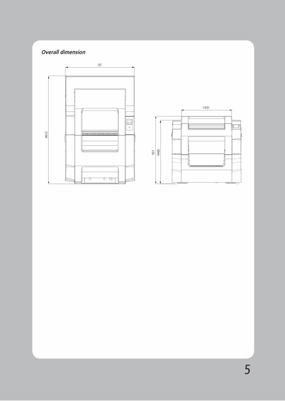
Overall dimension
6
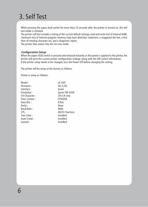
While pressing the paper feed switch for more than 10 seconds after the printer in turned on, the self test mode is initiated. The printer self test includes a listing of the current default settings, read and write test of internal RAM, checksum test of internal program memory, loop back detection statement, a staggered dot line, a few lines of rotating character set, and a diagnostic report. The printer then enters into the On-Line mode.
Configuration SetupWhen the paper FEED switch is pressed and released instantly as the power is applied to the printer, the printer will print the current printer configuration settings along with the DIP switch information. If the printer setup needs to be changed, turn the Power Off before changing the setting.
The printer will be setup at the factory as follows;
Printer is setup as follows:
Model : LK-D30Firmware : Ver X.XXInterface : SerialEmulation : Epson TM-U200CR Character : CR=CR onlyFlow Control : DTR/DSRData Bits : 8 BitsParity : NoneBaud Rate : 9600CPL : 40/33 Char/LineTwo Color : InstalledAuto Cutter : InstalledJournal : Installed
3. Self Test
7
Panel SwitchesPaper Feed button : Pressing the PF button momentarily will advance the paper one character line and
pressing it continuously will cause a fast feed at 15 lines per second.
Power Switch
A Power switch located on the lower left side of the printer is used to turn the printer on/off.
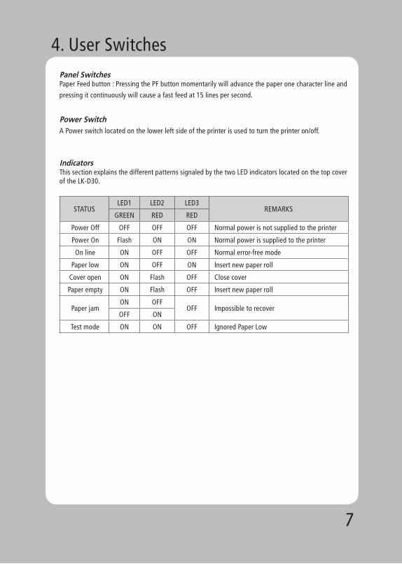
IndicatorsThis section explains the different patterns signaled by the two LED indicators located on the top cover of the LK-D30.
STATUSLED1 LED2 LED3
REMARKSGREEN RED RED
Power Off OFF OFF OFF Normal power is not supplied to the printer
Power On Flash ON ON Normal power is supplied to the printer
On line ON OFF OFF Normal error-free mode
Paper low ON OFF ON Insert new paper roll
Cover open ON Flash OFF Close cover
Paper empty ON Flash OFF Insert new paper roll
Paper jamON OFF
OFF Impossible to recoverOFF ON
Test mode ON ON OFF Ignored Paper Low
4. User Switches
8
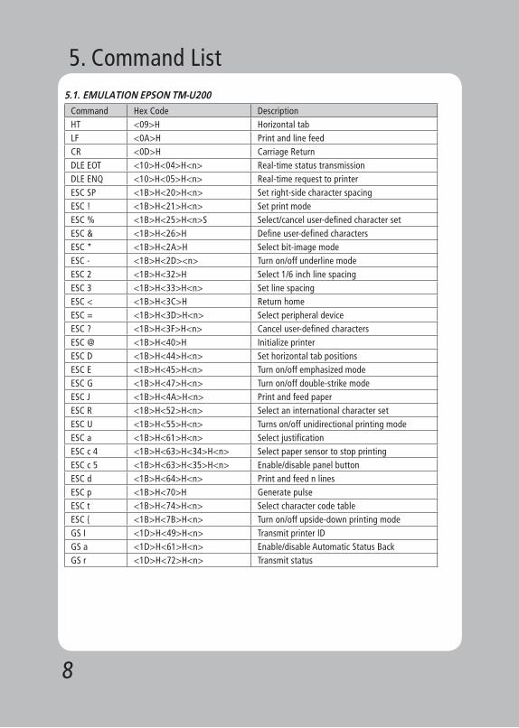
5.1. EMULATION EPSON TM-U200
Command Hex Code DescriptionHT <09>H Horizontal tabLF <0A>H Print and line feedCR <0D>H Carriage ReturnDLE EOT <10>H<04>H<n> Real-time status transmissionDLE ENQ <10>H<05>H<n> Real-time request to printerESC SP <1B>H<20>H<n> Set right-side character spacingESC ! <1B>H<21>H<n> Set print modeESC % <1B>H<25>H<n>S Select/cancel user-defined character setESC & <1B>H<26>H Define user-defined charactersESC * <1B>H<2A>H Select bit-image modeESC - <1B>H<2D><n> Turn on/off underline modeESC 2 <1B>H<32>H Select 1/6 inch line spacingESC 3 <1B>H<33>H<n> Set line spacingESC < <1B>H<3C>H Return homeESC = <1B>H<3D>H<n> Select peripheral deviceESC ? <1B>H<3F>H<n> Cancel user-defined charactersESC @ <1B>H<40>H Initialize printerESC D <1B>H<44>H<n> Set horizontal tab positionsESC E <1B>H<45>H<n> Turn on/off emphasized modeESC G <1B>H<47>H<n> Turn on/off double-strike modeESC J <1B>H<4A>H<n> Print and feed paperESC R <1B>H<52>H<n> Select an international character setESC U <1B>H<55>H<n> Turns on/off unidirectional printing modeESC a <1B>H<61>H<n> Select justificationESC c 4 <1B>H<63>H<34>H<n> Select paper sensor to stop printingESC c 5 <1B>H<63>H<35>H<n> Enable/disable panel buttonESC d <1B>H<64>H<n> Print and feed n linesESC p <1B>H<70>H Generate pulseESC t <1B>H<74>H<n> Select character code tableESC { <1B>H<7B>H<n> Turn on/off upside-down printing modeGS I <1D>H<49>H<n> Transmit printer IDGS a <1D>H<61>H<n> Enable/disable Automatic Status BackGS r <1D>H<72>H<n> Transmit status
5. Command List
9
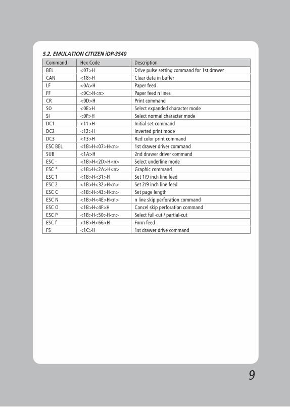
5.2. EMULATION CITIZEN iDP-3540
Command Hex Code DescriptionBEL <07>H Drive pulse setting command for 1st drawerCAN <18>H Clear data in bufferLF <0A>H Paper feedFF <0C>H<n> Paper feed n linesCR <0D>H Print commandSO <0E>H Select expanded character modeSI <0F>H Select normal character modeDC1 <11>H Initial set commandDC2 <12>H Inverted print modeDC3 <13>H Red color print commandESC BEL <1B>H<07>H<n> 1st drawer driver commandSUB <1A>H 2nd drawer driver commandESC - <1B>H<2D>H<n> Select underline modeESC * <1B>H<2A>H<n> Graphic commandESC 1 <1B>H<31>H Set 1/9 inch line feedESC 2 <1B>H<32>H<n> Set 2/9 inch line feedESC C <1B>H<43>H<n> Set page lengthESC N <1B>H<4E>H<n> n line skip perforation commandESC O <1B>H<4F>H Cancel skip perforation commandESC P <1B>H<50>H<n> Select full-cut / partial-cutESC f <1B>H<66>H Form feedFS <1C>H 1st drawer drive command

10
5.3. EMULATION STAR SP200
Command Hex Code Description
BEL <07>HDiffered drive command “A” for peripheral unit (Default setting)
CAN <18>H Cancel print data in bufferLF <0A>H Line feedCR <0D>H Line feed (same as LF)SO <0E>H Select expanded character modeSI <0F>H Cancel expanded character modeFS <1C>H Immediate drive command “B” for peripheral unit 1DC4 <14>H Cancel expanded character mode
ESC BEL n1 n2
<1B>H<07>H<n1><n2>Adjust drive pulse width for peripheral unit(Default setting)
ESC @ <1B>H<40>H Initialize printer
ESC M <1B>H<4D>HSelect 7 x 7 (Half dots) character size (Default setting)
ESC R n <1B>H<52>H<n> Select international character setESC P <1B>H<50>H Select 9 x 7 (Half dots) character size
ESC W 1<1B>H<57>H<31>H<1B>H<57>H<1>
Select expanded character mode
ESC W 0<1B>H<57>H<37>H<1B>H<57>H<0>
Cancel expanded character mode
ESC a n <1B>H<61>H<n> Feed paper n lines

11
6-1. Interface Connector
<D-SUB 25 Female Serial> <Centronics Parallel>
<USB “B” Type> <Ethernet>
<USB COMBO> <Wi-fi>
Serial Interface
PIN SIGNAL I/O DESCRIPTION2 TXD Output Printer transmit data line RS-232C level3 RXD Input Printer receive data line RS-232C level4, 20 DTR Output Printer handshake to host line RS-232C level6 DSR Input Data Send Ready1, 7 GND - System Ground
USB Interface
PIN SIGNAL I/O DESCRIPTION1 +5V - +5V2 DATA- - Printer transmit data line 3 DATA+ - Printer transmit data line 4 GND - System Ground
6. Interface

12
Centronics Parallel Interface
PIN SIGNAL I/O DESCRIPTION1 STROBE- Input Synchronize signal Data received2~9 DATA0~7 Input/Output Data bit Transmitted 0~710 ACK- Output Data receiving completed.11 BUSY Output Impossible to print of data receiving.12 PE Output Paper empty13 SELECT Output Printer status for ON/OFF line14 AUTO FEED- Input Paper auto feed signal15 GROUND - System ground16 GROUND - System ground17 NC -18 LOGIC-H - +5V19~30 GROUND - System ground31 INIT- Input Initialize32 ERROR- Output Printer error33 GROUND - System ground34 NC -35 +5V - +5V36 SELLECT IN- Input Printer select signal
Ethernet Interface
PIN SIGNAL I/O1 Data Out + Output Data +2 Data Out - Output Data -3 GND Ground4 Data IN + Input Data +5 Data IN - Input Data -6 N.C7 N.C8 N.C
13
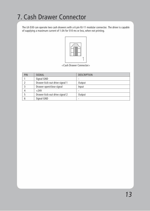
The LK-D30 can operate two cash drawers with a 6 pin RJ-11 modular connector. The driver is capable of supplying a maximum current of 1.0A for 510 ms or less, when not printing.
<Cash Drawer Connector>
PIN SIGNAL DESCRIPTION1 Signal GND -2 Drawer kick-out drive signal 1 Output3 Drawer open/close signal Input4 +24V -5 Drawer kick-out drive signal 2 Output6 Signal GND -
7. Cash Drawer Connector

14
The LK-D30 requires a power supply with the following parameters. A linear power Adapter is included in the LK-D30 box.
Power Supply Voltage : 24VDC±10%Power Supply Current : 2.5 A
<Power Supply Connector>
8. Electrical Specifications
15
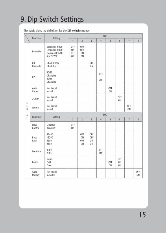
This table gives the definition for the DIP switch settings.
Function SettingSW1
1 2 3 4 5 6 7 8
SERIAL
Emulation
Epson TM-U200Epson TM-U300Citizen iDP3540Star SP200
OFFONOFFON
OFFOFFONON
ㄴㄴㄴㄴㄴㄴㄴㄴ
CRCharacter
CR=CR OnlyCR=CR + LF
OFFON
CPL
40/33 Char/Line42/35 Char/Line
OFF
ON
AutoCutter
Not InstallInstall
OFFON
2ColorNot InstallInstall
OFFON
JournalNot InstallInstall
OFFON
Function SettingSW2
1 2 3 4 5 6 7 8
FlowControl
DTR/DSRXon/Xoff
OFFON
Baud Rate
384001920096004800
OFFONOFFON
OFFOFFONON
Data Bits8 Bits 7 Bits
OFFON
ParityNoneOddEven
-OFFON
OFFONON
Auto Melody
Not InstallInstalled
OFFON
9. Dip Switch Settings

16
Function SettingSW1
1 2 3 4 5 6 7 8
PARALLEL
Emulation
Epson TM-U200Epson TM-U300Citizen iDP3540Star SP200
OFFOFFONON
OFFONOFFON
CRCharacter
CR=CR OnlyCR=CR + LF
OFFON
CPL40/33 Char/Line42/35 Char/Line
OFFON
AutoCutter
Not InstalledInstalled
OFFON
2 ColorNot InstalledInstalled
OFFON
JournalNot InstalledInstalled
OFFON
Function SettingSW2
1 2 3 4 5 6 7 8
AutoMelody
Not InstallInstalled
OFFON

17

18

19
Rev. 1.0
SEWOO TECH CO.,LTD.Doosung BD, 689-20, Geumjung-dong, Gunpo-si, Gyeonggi-do, 435-862 South Korea
TEL : +82-31-459-8200 FAX : +82-31-459-8880www.miniprinter.com