Embed Size (px)
Citation preview

INSTRUCTION MANUAL
SOLID STATE HF BAND 400W
MODEL : HL-450B
LINEAR AMPLIFIER

Thank you for purchasing the Tokyo Hy-Power HF band 400W linear amplifier model HL-450B. The HL-450B is a solid state linear amplifier having maximum output of 400 W (PEP) on HF band, making full use of the latest semiconductor circuit technology. It is best suited for the mobile operation as well as the base station work combining with the optional DC power supply, HP-450. Read this instruction manual thoroughly first so that you may work the amplifier properly. 1. Features The HL-450B has a built-in auto band-select function. It uses a newly developed micro
processor based technology, and works a smooth automatic operation when driven by the radio. In addition, manual band setting is possible as well. It is designed to be “user friendly”.
Since the HL-450B is compatible with our optional external remote controller (HRC-60),
operation is possible from remote locations, if plugged into the socket at the rear panel. The HL-450B is equipped with a hard-key terminal to make a smooth send/receive
switching with the radio, and also an output terminal for ALC circuit which controls the output of the radio. ALC helps suppress excessive output and avoid the signal distortion.
The HL-450B has various protection circuits such as for high antenna SWR, over drive,
over current etc. When any abnormal condition is detected, operation is automatically shut down to prevent the failure.
The large analog power meter is easy to read and the output can always be monitored. The HL-450B is designed to comply with the new FCC rule of Part 97, issued in
December 2006.

2. Precaution Note the followings to prevent the failure, and to achieve the best performance of the HL-450B. Check the maximum power handling capacity of the antenna. (Needs 400 W PEP
rating at least.) Check also the antenna SWR, and SWR should be lowered to 1.5 or the vicinity by adjusting the element and/or the antenna system when SWR is too high.
Never Transmit with no antenna connected to ANT terminal. Maximum drive power is 50 W. Never exceed this limit.
(If the transmission duty is far longer than the reception, reduce the drive power accordingly.)
Use 50 coaxial cable for all connections. Keep the power supply voltage at DC 13.8 V (or within 12 to 14 V). Never connect to
higher DC voltage and AC 115 V line, or amp will be killed. The amplifier is cooled by forced airflow. Several inches of clearance on the side and
the rear wall are necessary to allow for smooth air exhaust from the fan. Do not block the air vents on the top cover. Keep the amplifier out of direct sunlight, in a cool dry environment.
If strong physical shock is applied to the HL-450B, internal parts may be damaged.
Handle the amplifier carefully especially during transportation to avoid the direct shock to be given.

3. Specifications Frequency All HF amateur bands of 3.5-28 MHz including WARC bands.
Mode SSB (A3E), CW (A1A), FM (F3E)
Output SSB (PEP)/CW 400 W max., 350 W typ., 300 W min.
RF Input 50 W DC Power Supply
DC 13.8 V 60 A max.
Input/Output Impedance
50 Final Transistor THP-120×4
Cooling System Forced-air cooling
Input/Output Connector UHF (SO-239) Built-in functions
1. Send/receive switching terminal (hard key) 2. Protection circuit (antenna SWR, over-current, over-voltage,
over-drive, over-temperature, band mis-set) 3. Output power meter 4. ALC terminal 5. External controller (HRC-60, optional parts) terminal
Accessories
DC power cord (red/black pair) 6’ × 1 Coaxial jumper cable: 2’ × 1 Stand-by cable (with RCA plug) 4’ × 1 Spare fuses: 30 A × 4 Instruction manual, warranty card
Dimensions and weight
220(W) × 90(H) × 330(D) mm approx. 5 kgs. 8.7(W) × 3.5(H) × 13(D) inches approx. 11lbs.

4. Explanations of Front and Rear Panels
① POWER (Power Switch)
This switch turns the power on and off. When OFF, the linear amplifier enters the through state. (At the through state, the output power of the radio passes through the amplifier and is supplied to the antenna directly. In addition, the received signal from the antenna is fed to the radio directly.)
② AUTO/MANU (Auto/Manual Band Switch)
The band switching modes between auto and manual can be selected by pushing the button. When the LED lights, auto band switch is selected. Otherwise, manual mode has been selected. The band is shifted upward every time the button is pressed.
③ PROT (Protection)
When an abnormality such as over-drive, internal over-temperature, DC over-voltage, or high antenna SWR occurs, the protection circuit shuts down the amplifier to enter the through state. And “PROT” LED lights. When the cause of the shut down is corrected, turn the POWER switch off and on to reset the amplifier.
④ ON AIR
This lights when the HL-450B enters the transmission state. ⑤ Meter
This displays the output power.

⑥ DC Power Terminal
Connect the HL-450B to a regulated DC power supply or 12 V battery using the included DC power cord. The red cord is positive (+) and the black one is negative (-). 60 A min. (peak) capacity is required. Use the supplied cord of the accessories or the equivalent wire size to avoid the voltage drop.
⑦ ALC Pot
This pot is used to adjust the ALC output level. When it is gradually turned counterclockwise, a negative DC voltage is obtained and the RF output is decreased. Adjust the pot so that the drive power stays within 50 W max, and/or the desired output power level is achieved. (This ALC pot works when the ⑧ALC terminal is connected to the external ALC input terminal of the radio.) In the case of 400 W output, the DC voltage up to -10 V max. is produced as the ALC voltage. (Refer to (6) at page 7.)
⑧ ALC (Phono Jack)
Connect one end of the supplied ALC cable to ⑧ALC jack and the other end to the (Ext) ALC jack of the radio. ALC helps suppress the over-drive to keep the amplified output level at the desired level. (a. Effective external ALC voltage differs from radio to radio. Usually -4 V to -6 V. (b. If the radio is 50 W max model, or if the radio is worked modestly not to exceed 50
W output level, this ALC connection is not necessarily required.)

⑨ TX (TX Coax Connector) Connect the coaxial cable (50 ) from the radio.
⑩ ANT (Antenna Coaxial Connector)
Connect the coaxial cable (50 ) of the antenna. Antenna must have a sufficient power handling capability (400 W), and low SWR value of 1.5 typ., 1.8 max..
⑪ ACC (Remote Controller Connection Terminal)
This is a DIN socket for connecting the remote head (HRC-60, optional parts), which enables turning on and off of the power as well as monitoring various operation status in a remote location.
⑫ STBY (Phono Jack)
Be sure to connect this STBY to the radio for hard keying the amplifier. When this STBY terminal is grounded, the HL-450B enters the transmission state. Connect this terminal with the ACC terminal (or REMOTE terminal) of the radio. (The name of the terminal may differ depending on the radio. For example, ICOM: “SEND”, YAESU: “TX GND”, and others: “REMOTE”, etc.)
5. Connection
(※Note: It may be called “SEND”, “TX GND” and so on depending on the manufacturer.)

6. Operation (1) Check the connection of each cable again by referring to the illustration at page 6.
Turn on the power of the radio. Leave the power switch of this amplifier off. In the receiving state, the received signal from the antenna passes through the amplifier, and you can hear the received signal sound from the radio. Use an antenna that handles rf power of 400 W PEP minimum.
(2) Next, select an empty frequency channel, and check the matching state of the antenna
with an SWR meter. Use CW mode. If the SWR is too high, check the antenna system or adjust the element length. Keep the SWR within 1.5.
(3) If the antenna matching is good, turn on the power of the amplifier. (4) Select either AUTO (automatic) or MANU (manual).
When AUTO mode is selected, LED of AUTO/MANU lights. Key the radio to drive the amplifier. When in MANU (manual) mode, press the button and the LED of the selected band lights. The band is shifted upward every time the button is pressed.
(5) When the radio is keyed into the transmission state, the HL-450B is automatically
switched to the transmission (amplification state), and a high output power is emitted from the antenna. Then, the power meter swings according to the output level.
(6) Adjust the ALC pot of the HL-450B, and suppress the maximum output to 400 W or the
desired level. (In this case, the output of the transceiver is suppressed to a maximum of 50 W.) The ALC pot is turned fully clockwise at the factory shipment, and the output voltage is set to DC 0 V. When it is gradually turned counter-clockwise, a negative ALC voltage (–1 to –10 V) is generated. Adjust the voltage according to the ALC design of the radio. (Generally, the ALC works at approx. –4 V with ICOM, and at –4 V to –6 V with YAESU and KENWOOD.)
(7) When operating without this amplifier (or bare foot), simply turn off the power switch of
this amplifier with each cable left as it is. The reception/transmission signal to and from the radio passes through the inside of this amplifier.

7. Protection and Treatment for Shutdown The HL-450B is equipped with the following six protection functions, and the LED of “PROT” lights when an abnormality is detected. (1) Over-Voltage
The LED of “PROT” lights when the power supply voltage exceeds 16 V. Check the DC power voltage.
(2) Antenna SWR
The LED of “PROT” lights when the matching condition of the antenna is poor and the SWR exceeds 2. Check the maximum power handling capacity of the antenna, and lower the SWR accordingly.
(3) Over-Drive
The LED of “PROT” lights when the RF drive from the radio exceeds 50 W. Adjust the drive level of the radio not to exceed 50 W. Make the ALC connection, if needed.
(4) Band Mis-Set
The LED of “PROT” lights when the amplifier is driven by a higher frequency signal than the selected frequency band in manual mode. Correct the band selection.
(5) Over-Current
The LED of “PROT” lights when DC current of 65 A or more flows into the amplifier. DC current flow varies depending on SWR condition of the antenna. Correct the matching or reduce the drive power.
(6) Over-Temperature
The LED of “PROT” lights when the internal temperature reaches 70C. Leave it in the standby state (receiving) for a while until the temperature falls.
(7) RF Stray and Odd Shut Down It may happen that a part of the amplified large RF signal intrudes into the radio system to cause such an instable behavior during the transmission, that the transmission signal gets distorted, and that DC power supply voltage jumps up. To cure these troubles, it is suggested that clip-on ferrite cores are inserted at both ends of all the DC power and control cables as well as coax cables. Such ferrite cores are available from Amidon Associates, Palomar Engineers, TDK Corp. and so on. When “PROT” LED lights, you need to reset the amplifier to release the shut-down. After checking possible causes of shut-down, turn off and on the POWER switch to reset.
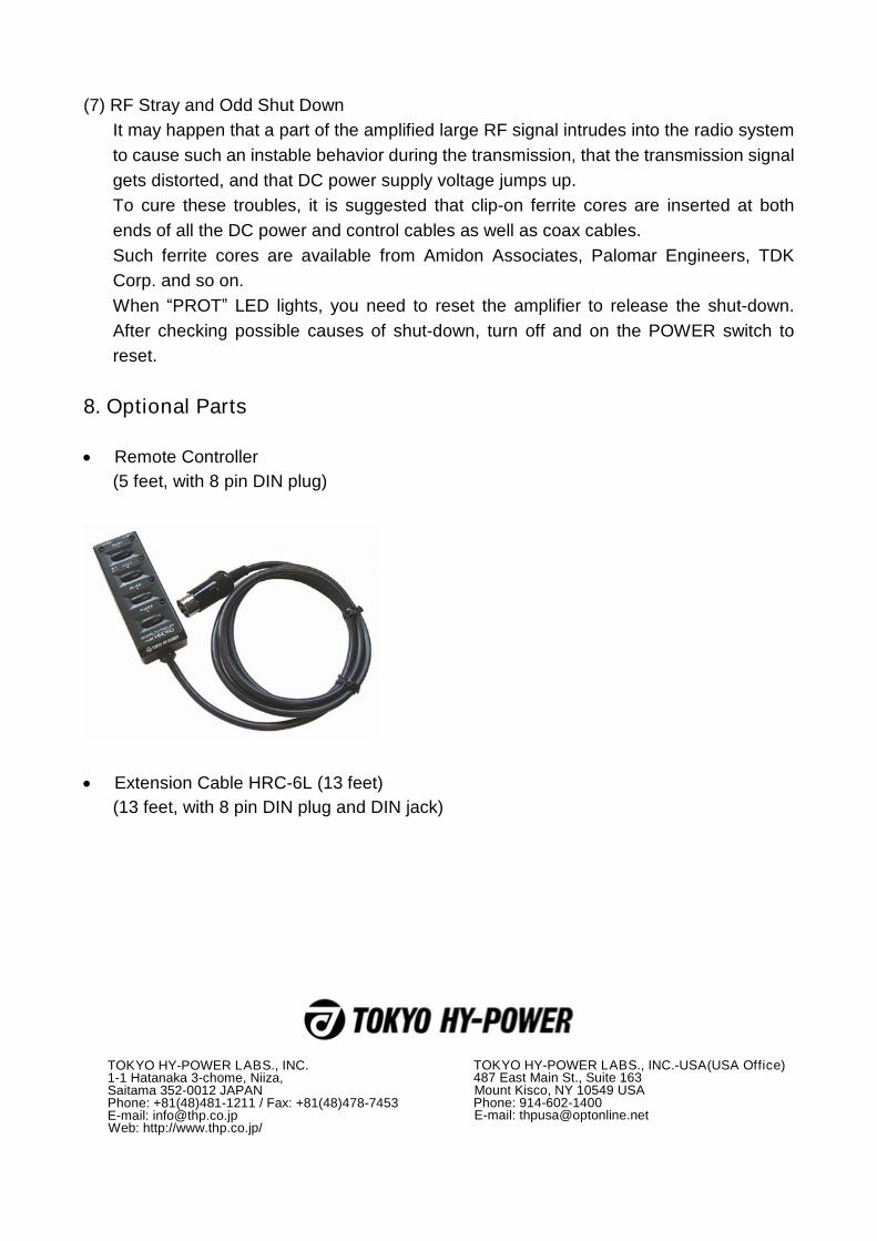
8. Optional Parts Remote Controller
(5 feet, with 8 pin DIN plug)
Extension Cable HRC-6L (13 feet)
(13 feet, with 8 pin DIN plug and DIN jack)
TOKYO HY-POWER LABS., INC. 1-1 Hatanaka 3-chome, Niiza, Saitama 352-0012 JAPAN Phone: +81(48)481-1211 / Fax: +81(48)478-7453 E-mail: [email protected] Web: http://www.thp.co.jp/
TOKYO HY-POWER LABS., INC.-USA(USA Office) 487 East Main St., Suite 163 Mount Kisco, NY 10549 USA Phone: 914-602-1400 E-mail: [email protected]