Embed Size (px)
Citation preview

Operator’s Manual
Top DresserModel GT-100
THIS MANUAL MUST BE READ AND UNDERSTOOD BEFORE ANYONE OPERATES THIS MACHINE!
Manual# 990036Revised 01/2010
YOU MUST FILL OUT YOUR WARRANTY REGISTRATION TO ACTIVATE YOUR WARRANTY AND TO QUALIFY FOR PARTS AND SERVICE!!
To the Owner;Thank-You for choosing a quality topdresser from Pequea Machine, Inc. We strive to give you the best equipment and the best level of service of any company. With a little care and maintenance this machine will do your work for you for many years. In this manual, we make an effort to get you better acquainted with the topdresser so you can achieve maximum performance. We design and build all of our equipment with the end user in mind so we welcome any suggestions or ideas for improvement.
Please take a few minutes to fill out the area below. This information will be valuable to you when ordering parts or requesting service from your dealer.
Dealer Name:_____________________________
Dealer Phone Number:______________________
Service Manager/Technician:_________________
Model# and Description:_____________________
Serial Number:____________________________
Date of Purchase:__________________________
1
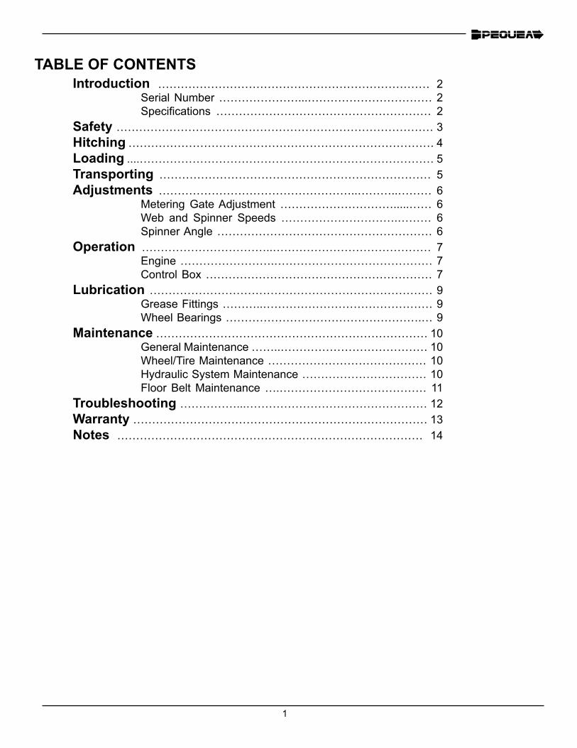
TABLE OF CONTENTSIntroduction ……………………………………………………………… 2
Serial Number …………………...…………………………… 2Specifications ………………………………………………… 2
Safety ………………………………………………………………………… 3Hitching ……………………………………………………………………… 4Loading ....…………………………………………………………………… 5Transporting ……………………………………………………………… 5Adjustments ……………………………………………..………..……… 6
Metering Gate Adjustment ………………………….....…… 6Web and Spinner Speeds ………………………….……… 6Spinner Angle ………………………………………………… 6
Operation ……………………………..…………………………………… 7Engine …………………….…………………………………… 7Control Box …………………………………………………… 7
Lubrication ………………………………………………………………… 9Grease Fittings ………..……………………………………… 9Wheel Bearings …………………………………………….… 9
Maintenance ……………………………………………………………… 10General Maintenance ……..………………………………… 10Wheel/Tire Maintenance …………………………………… 10Hydraulic System Maintenance …………………………… 10Floor Belt Maintenance ….………………………………… 11
Troubleshooting ……………...………………………………………… 12Warranty …………………………………………………………………… 13Notes ……………………………………………………………………… 14
2
INTRODUCTIONContained in this manual is information pertaining to the operation, adjustment and maintenance of the Pequea GT-100. Proper care and operation will assure you many years of reliable, accurate performance. Be sure to have all operators read this manual carefully before operation.
The Pequea dealer from whom you purchased this topdresser will instruct you in its general opera-tion. Your dealer’s staff of technicians will be glad to answer any questions that may arise regard-ing the operation of your topdresser.
A complete line of Pequea replacement parts is available through your dealer. These parts have been inspected at Pequea and are manufactured by the same high quality standards as your top-dresser, to insure an accurate fit.
Because Pequea continually strives to improve our products, we reserve the right to make chang-es and improvements wherever it is practical, without obligation to make those same changes or improvements to the equipment sold previously
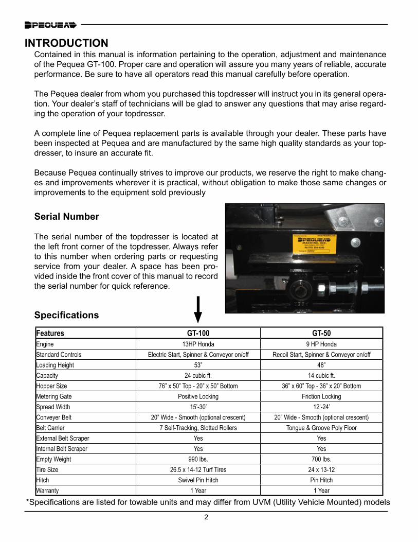
Specifications
Features GT-100 GT-50Engine 13HP Honda 9 HP HondaStandard Controls Electric Start, Spinner & Conveyor on/off Recoil Start, Spinner & Conveyor on/offLoading Height 53” 48”Capacity 24 cubic ft. 14 cubic ft.Hopper Size 76” x 50” Top - 20” x 50” Bottom 36” x 60” Top - 36” x 20” BottomMetering Gate Positive Locking Friction LockingSpread Width 15’-30’ 12’-24’Conveyer Belt 20” Wide - Smooth (optional crescent) 20” Wide - Smooth (optional crescent)Belt Carrier 7 Self-Tracking, Slotted Rollers Tongue & Groove Poly FloorExternal Belt Scraper Yes YesInternal Belt Scraper Yes YesEmpty Weight 990 lbs. 700 lbs.Tire Size 26.5 x 14-12 Turf Tires 24 x 13-12Hitch Swivel Pin Hitch Pin HitchWarranty 1 Year 1 Year
Serial Number
The serial number of the topdresser is located at the left front corner of the topdresser. Always refer to this number when ordering parts or requesting service from your dealer. A space has been pro-vided inside the front cover of this manual to record the serial number for quick reference.
*Specifications are listed for towable units and may differ from UVM (Utility Vehicle Mounted) models
3
SAFETY
Do not clean, lubricate, or make any adjustments to the topdresser while it is in motion.
Do not start the topdresser until everyone is clear of the machine and its spreading radius.
Ensure that all tools and foreign objects have been removed from the machine before starting.
Keep hands, feet, clothing, or jewelry away from all moving parts.
Do not attempt to pull material from any part of the topdresser while it is in opera-tion.
Replace all shields after lubrication or repairs.
Never allow riders on the topdresser.
Park on level ground and block the wheels to prevent topdresser from rolling.
Pequea Machine, Inc. assumes no liability for injuries sustained because of failure to read this manual or from carelessness by the operator. Always refer to this manual for guid-ance or contact your dealer.
4
HITCHING
Check tires to make sure they are inflated to the correct pressure. Recommended pressure is written on the sidewall of the tire.
Torque the wheel bolts to 120 ft. lbs. and recheck periodically thereafter.
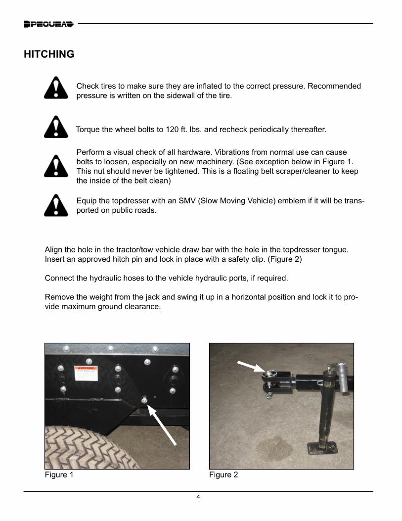
Perform a visual check of all hardware. Vibrations from normal use can cause bolts to loosen, especially on new machinery. (See exception below in Figure 1. This nut should never be tightened. This is a floating belt scraper/cleaner to keep the inside of the belt clean)
Equip the topdresser with an SMV (Slow Moving Vehicle) emblem if it will be trans-ported on public roads.
Align the hole in the tractor/tow vehicle draw bar with the hole in the topdresser tongue. Insert an approved hitch pin and lock in place with a safety clip. (Figure 2)
Connect the hydraulic hoses to the vehicle hydraulic ports, if required.
Remove the weight from the jack and swing it up in a horizontal position and lock it to pro-vide maximum ground clearance.
Figure 1 Figure 2
5
TRANSPORTING
Always load the topdresser on a level surface and only when hitched to the tow vehicle. Be sure to engage the parking brake of the tow vehicle. UVM Models; Be sure to have the parking brake set when loading.
Always load the front first and finish at the rear.
Never exceed the maximum weight load as shown on each tire. To calculate your maximum weight limit, multiply the tire rating times the number of tires and subtract the empty weight of the topdresser.
Avoid keeping the topdresser loaded for long periods of time. Some materials are acidic, and although the sides are galvanized, some parts of the spreader may begin to rust and deteriorate.
The GT Series Topdressers are designed to travel safely at highway speeds only when empty. Attempting to travel at highway speeds while loaded may cause damage to the tires, wheel bearings, and may impair your ability to drive safely. See imprint on the sidewall of the tire for maximum speed rating and do not exceed this speed.
Slow down when turning to avoid instability and loss of control.
Do not travel on the road at night. Your topdresser is not equipped with lights.
Follow all local regulations for moving equipment on public roads.
LOADING
When storing the loaded topdresser outside, be sure to keep the load covered. Some materials, when saturated with rain will become very heavy and exceed the maximum load rating of the topdresser.
Do not allow the topdresser to be stored outside in freezing conditions. If the material becomes wet it will freeze and expand and could cause damage to the topdresser sides.
6
ADJUSTMENTS
Metering Gate Adjustment
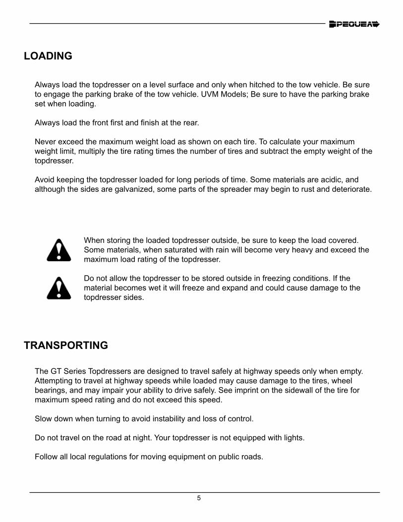
The rear metering gate is on a manually operated slide. Pull back the spring loaded locking pin and turn the me-tering disc until the gate is at the desired location. Turn the handle clockwise to raise the gate and counter-clock-wise to lower it.
Web and Spinner Speeds
The web and spinner speed is controlled by the adjust-ment knobs on the left side of the topdresser. The knob on the left controls the spinners and the one on the right controls the floor speed. The speed increases when the knob is turned counter-clockwise and decreases when it is turned clockwise.
Spinner Angle
The angle of the spinners can be adjusted to allow for greater control in depth, width and penetration of spread material. Loosen the locking handle and manually move the spinner frame to the desired angle then retighten the locking handle.
Locking Handle
Figure 3
Figure 4
Figure 5
7
OPERATION
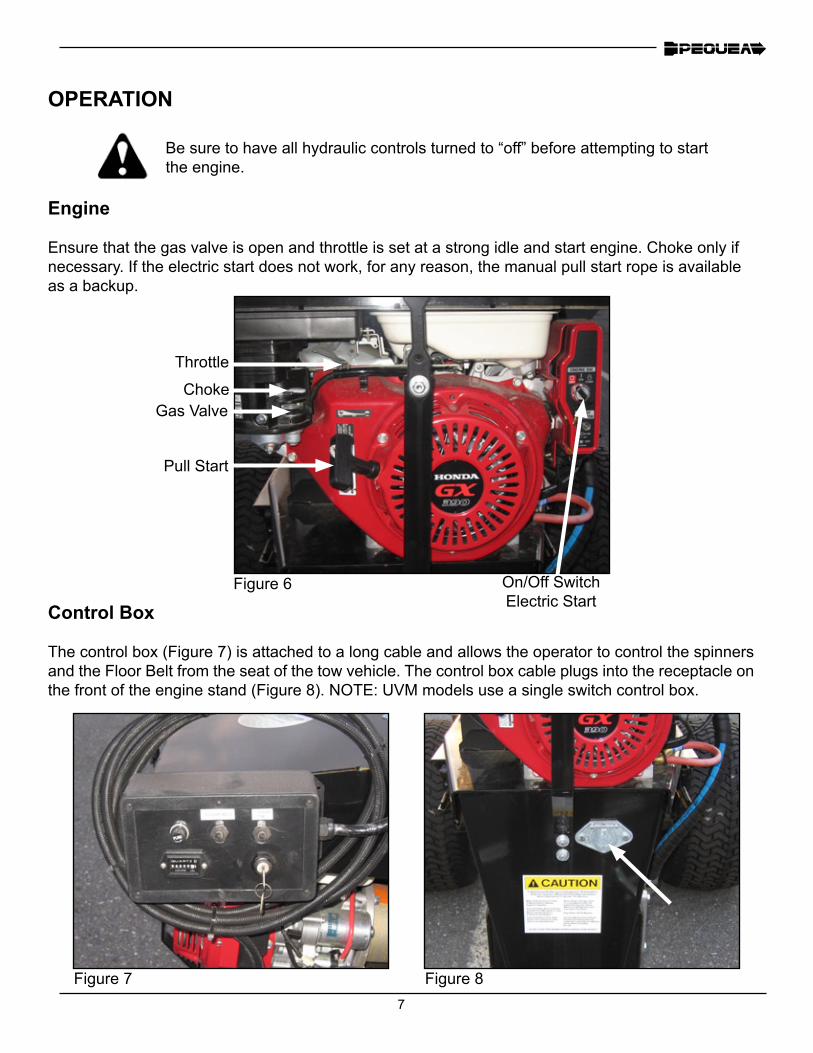
Be sure to have all hydraulic controls turned to “off” before attempting to start the engine.
On/Off Switch Electric Start
Gas ValveChoke
Throttle
Pull Start
Engine
Ensure that the gas valve is open and throttle is set at a strong idle and start engine. Choke only if necessary. If the electric start does not work, for any reason, the manual pull start rope is available as a backup.
Control Box
The control box (Figure 7) is attached to a long cable and allows the operator to control the spinners and the Floor Belt from the seat of the tow vehicle. The control box cable plugs into the receptacle on the front of the engine stand (Figure 8). NOTE: UVM models use a single switch control box.
Figure 7
Figure 6
Figure 8
8
NOTE: A number of factors will determine how the material is spread. While this manual will attempt to provide basic starting adjustments, the most effective operation will be determined from experience.
• Rear Gate Opening -
• Spinner Speed -
• Floor Belt Speed -
• Ground Speed -
• On Board Hydraulics -
For most materials begin with the gate open approximately 1-1/2” ad-just to greater or lesser opening to increase or decrease material flow. The gate opening adjusts from closed to 8”
Normal speed of dual spinners creates up to a 35’ spread pattern of most material. Reducing the spinner speed causes the spread pattern to be narrower, but with greater depth.
Faster belt speeds increase the volume of material to the spinners, thereby increasing distribution. Belt speed varies from 0 to 120 feet per minute.
Optimum ground speed for topdressing is approximately 6 MPH. This speed will vary according to application rate, type of material being spread, and weather conditions. Dampness affects the rate at which some materials spread. Vary speed accordingly from 2 to 8 MPH
Maintain engine speed at highest rpm. Engine throttle is preset at fac-tory to maintain proper hydraulic pump pressure.
OPERATION
9
LUBRICATION
Grease Fittings
The GT-100 is designed to require minimal lubrication and maintenance. However, the impor-tance of sufficient and proper lubrication cannot be over emphasized as it is the best insurance against unnecessary repairs and will greatly increase the life and performance of the machine.
The operator should become familiar with all lubrication points and establish a systematic routine to ensure complete and quick lubrication of the machine.
Lubricate all the grease fittings once a month or every 100 loads, whichever comes first. Be care-ful not to over grease the sealed bearings as too much grease could push out the seal and allow dirt or sand to contaminate the bearing. One half of a stroke from a manual grease pump should be sufficient. Be sure to wipe all the dust and chaff away from the grease fitting before greasing. If it is not clean you might force some dirt into the bearing.
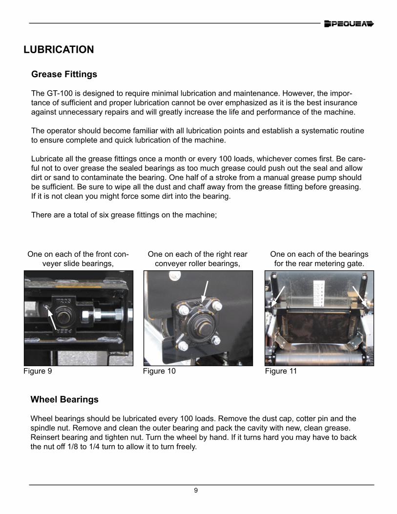
There are a total of six grease fittings on the machine;
One on each of the front con-veyer slide bearings,
One on each of the right rear conveyer roller bearings,
One on each of the bearings for the rear metering gate.
Figure 9 Figure 10 Figure 11
Wheel Bearings
Wheel bearings should be lubricated every 100 loads. Remove the dust cap, cotter pin and the spindle nut. Remove and clean the outer bearing and pack the cavity with new, clean grease. Reinsert bearing and tighten nut. Turn the wheel by hand. If it turns hard you may have to back the nut off 1/8 to 1/4 turn to allow it to turn freely.
10
MAINTENANCE
General Maintenance
• Remove spread material buildup regularly
• Protect the machine from the weather when it is not in use. (Store indoors or cover with a tarp)
• Check the rubber apron belt scrapers to make sure they are down against the apron belt.
• Regularly check for loose or worn parts. Particularly check the common wear parts such as bear-ings, spinner paddles, apron belt, etc.
Wheel/Tire Maintenance
• Check the wheel lug bolt torque once a month. Recommended torque is 120 ft. lbs.
• Check tire air pressure. Recommended pressure rating is printed on the sidewall of the tire.
Hydraulic System Maintenance
• Periodically check the condition of the hydraulic hoses for flexibility and check for any signs of rubbing or wearing on the hoses.
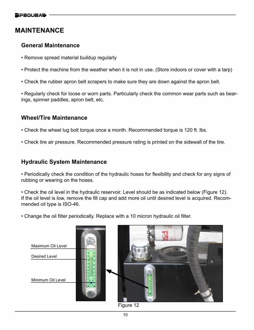
• Check the oil level in the hydraulic reservoir. Level should be as indicated below (Figure 12). If the oil level is low, remove the fill cap and add more oil until desired level is acquired. Recom-mended oil type is ISO-46.
• Change the oil filter periodically. Replace with a 10 micron hydraulic oil filter.
Figure 12
Maximum Oil Level
Desired Level
Minimum Oil Level
11
MAINTENANCE
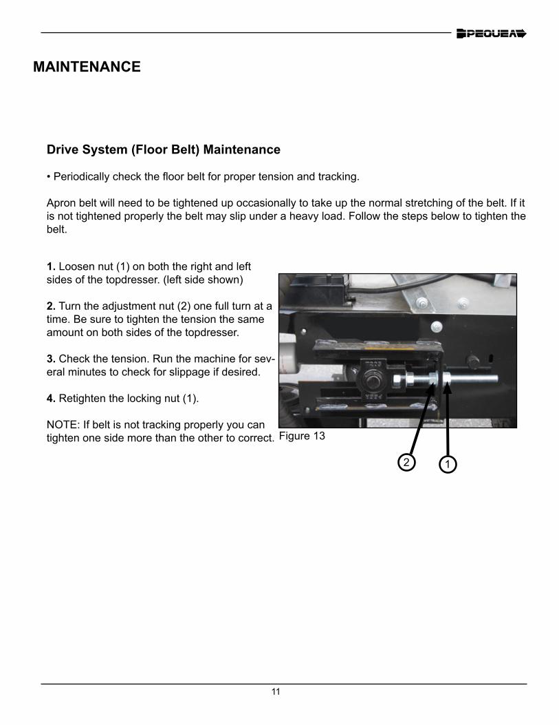
Drive System (Floor Belt) Maintenance
• Periodically check the floor belt for proper tension and tracking.
Apron belt will need to be tightened up occasionally to take up the normal stretching of the belt. If it is not tightened properly the belt may slip under a heavy load. Follow the steps below to tighten the belt.
2 1
Figure 13
1. Loosen nut (1) on both the right and left sides of the topdresser. (left side shown)
2. Turn the adjustment nut (2) one full turn at a time. Be sure to tighten the tension the same amount on both sides of the topdresser.
3. Check the tension. Run the machine for sev-eral minutes to check for slippage if desired.
4. Retighten the locking nut (1).
NOTE: If belt is not tracking properly you can tighten one side more than the other to correct.
12
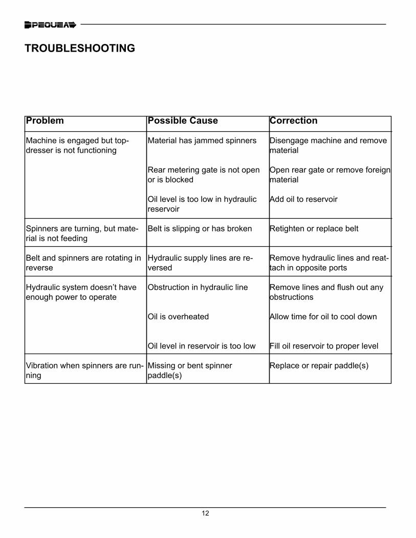
Problem
Machine is engaged but top-dresser is not functioning
Spinners are turning, but mate-rial is not feeding
Belt and spinners are rotating in reverse
Hydraulic system doesn’t have enough power to operate
Vibration when spinners are run-ning
Possible Cause
Material has jammed spinners
Rear metering gate is not open or is blocked
Oil level is too low in hydraulic reservoir
Belt is slipping or has broken
Hydraulic supply lines are re-versed
Obstruction in hydraulic line
Oil is overheated
Oil level in reservoir is too low
Missing or bent spinner paddle(s)
Correction
Disengage machine and remove material
Open rear gate or remove foreign material
Add oil to reservoir
Retighten or replace belt
Remove hydraulic lines and reat-tach in opposite ports
Remove lines and flush out any obstructions
Allow time for oil to cool down
Fill oil reservoir to proper level
Replace or repair paddle(s)
TROUBLESHOOTING
13
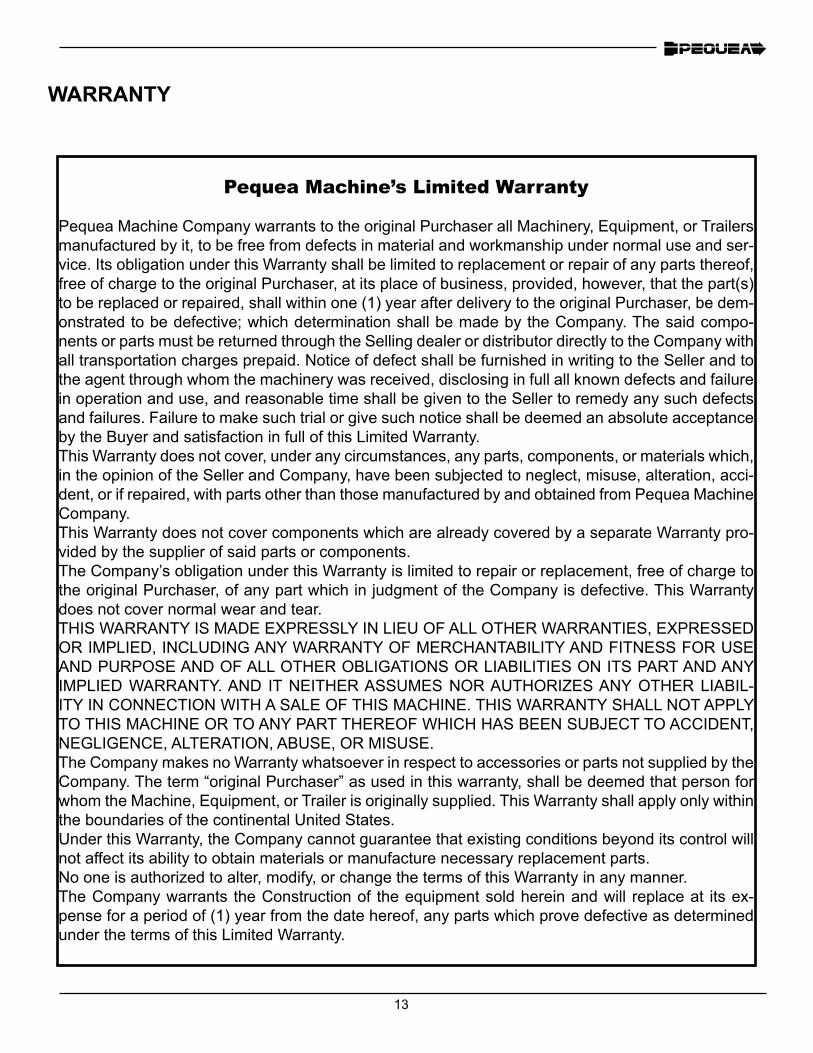
Pequea Machine’s Limited Warranty
Pequea Machine Company warrants to the original Purchaser all Machinery, Equipment, or Trailers manufactured by it, to be free from defects in material and workmanship under normal use and ser-vice. Its obligation under this Warranty shall be limited to replacement or repair of any parts thereof, free of charge to the original Purchaser, at its place of business, provided, however, that the part(s) to be replaced or repaired, shall within one (1) year after delivery to the original Purchaser, be dem-onstrated to be defective; which determination shall be made by the Company. The said compo-nents or parts must be returned through the Selling dealer or distributor directly to the Company with all transportation charges prepaid. Notice of defect shall be furnished in writing to the Seller and to the agent through whom the machinery was received, disclosing in full all known defects and failure in operation and use, and reasonable time shall be given to the Seller to remedy any such defects and failures. Failure to make such trial or give such notice shall be deemed an absolute acceptance by the Buyer and satisfaction in full of this Limited Warranty.This Warranty does not cover, under any circumstances, any parts, components, or materials which, in the opinion of the Seller and Company, have been subjected to neglect, misuse, alteration, acci-dent, or if repaired, with parts other than those manufactured by and obtained from Pequea Machine Company.This Warranty does not cover components which are already covered by a separate Warranty pro-vided by the supplier of said parts or components.The Company’s obligation under this Warranty is limited to repair or replacement, free of charge to the original Purchaser, of any part which in judgment of the Company is defective. This Warranty does not cover normal wear and tear.THIS WARRANTY IS MADE EXPRESSLY IN LIEU OF ALL OTHER WARRANTIES, EXPRESSED OR IMPLIED, INCLUDING ANY WARRANTY OF MERCHANTABILITY AND FITNESS FOR USE AND PURPOSE AND OF ALL OTHER OBLIGATIONS OR LIABILITIES ON ITS PART AND ANY IMPLIED WARRANTY. AND IT NEITHER ASSUMES NOR AUTHORIZES ANY OTHER LIABIL-ITY IN CONNECTION WITH A SALE OF THIS MACHINE. THIS WARRANTY SHALL NOT APPLY TO THIS MACHINE OR TO ANY PART THEREOF WHICH HAS BEEN SUBJECT TO ACCIDENT, NEGLIGENCE, ALTERATION, ABUSE, OR MISUSE.The Company makes no Warranty whatsoever in respect to accessories or parts not supplied by the Company. The term “original Purchaser” as used in this warranty, shall be deemed that person for whom the Machine, Equipment, or Trailer is originally supplied. This Warranty shall apply only within the boundaries of the continental United States.Under this Warranty, the Company cannot guarantee that existing conditions beyond its control will not affect its ability to obtain materials or manufacture necessary replacement parts.No one is authorized to alter, modify, or change the terms of this Warranty in any manner.The Company warrants the Construction of the equipment sold herein and will replace at its ex-pense for a period of (1) year from the date hereof, any parts which prove defective as determined under the terms of this Limited Warranty.
WARRANTY

14
NOTES


200 Jalyn Drive P.O. Box 399
New Holland PA 17557
Phone: 717-354-4343Fax: 717-354-8843
E-mail: [email protected]