Embed Size (px)
Citation preview
February 2019
Technical Data Submittal Document
Model GPDDiesel Engine Driven Fire Pump Controller
Contents:Data Sheets
Dimensional DataWiring SchematicsField Connections
Project: Customer: Engineer: Pump Manufacturer:
The drawings included in this package are for controllers covered under our standard offering. Actual AS BUILT drawings may differ from what is shown in this package.
Note:
February 2019 2
Technical DataModel GPD Diesel Fire Pump Controller
This is a Marketing document. Please consult factory for more information. Manufacturer reserves the right to modify this information without notice
Standard,Listings,
Approvals andCertifications
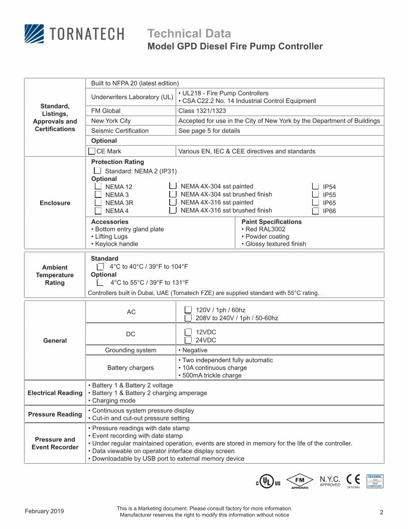
Built to NFPA 20 (latest edition)
Underwriters Laboratory (UL) • UL218 - Fire Pump Controllers• CSA C22.2 No. 14 Industrial Control Equipment
FM Global Class 1321/1323New York City Accepted for use in the City of New York by the Department of BuildingsSeismic Certification See page 5 for detailsOptional CE Mark Various EN, IEC & CEE directives and standards
Enclosure
Protection Rating □ Standard: NEMA 2 (IP31)Optional□ NEMA 12□ NEMA 3□ NEMA 3R□ NEMA 4
Accessories• Bottom entry gland plate• Lifting Lugs• Keylock handle
Paint Specifications• Red RAL3002• Powder coating• Glossy textured finish
□ NEMA 4X-304 sst painted□ NEMA 4X-304 sst brushed finish□ NEMA 4X-316 sst painted□ NEMA 4X-316 sst brushed finish
□ IP54□ IP55□ IP65□ IP66
Ambient Temperature
Rating
Standard □ 4°C to 40°C / 39°F to 104°FOptional □ 4°C to 55°C / 39°F to 131°F
Controllers built in Dubai, UAE (Tornatech FZE) are supplied standard with 55°C rating.
General
AC □ 120V / 1ph / 60hz□ 208V to 240V / 1ph / 50-60hz
DC □ 12VDC□ 24VDCGrounding system • Negative
Battery chargers• Two independent fully automatic• 10A continuous charge• 500mA trickle charge
Electrical Reading• Battery 1 & Battery 2 voltage• Battery 1 & Battery 2 charging amperage• Charging mode
Pressure Reading • Continuous system pressure display • Cut-in and cut-out pressure setting
Pressure and Event Recorder
• Pressure readings with date stamp• Event recording with date stamp• Under regular maintained operation, events are stored in memory for the life of the controller.• Data viewable on operator interface display screen• Downloadable by USB port to external memory device
February 2019 3
Technical DataModel GPD Diesel Fire Pump Controller
This is a Marketing document. Please consult factory for more information. Manufacturer reserves the right to modify this information without notice
*Except if option C13 is ordered. Tornatech reserves the right to use any of these four alarm points for special specific application requirements**Applicable to electronic engines only. *** Applicable to electronic engines only. Alarms when ECM selector switch on the engine is in alternate mode.
Pressure sensing
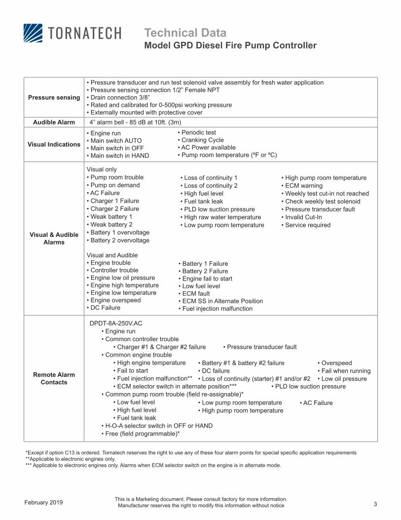
• Pressure transducer and run test solenoid valve assembly for fresh water application• Pressure sensing connection 1/2” Female NPT• Drain connection 3/8” • Rated and calibrated for 0-500psi working pressure • Externally mounted with protective cover
Audible Alarm 4” alarm bell - 85 dB at 10ft. (3m)
Visual Indications
• Engine run • Main switch AUTO • Main switch in OFF • Main switch in HAND
Visual & Audible Alarms
Visual only • Pump room trouble • Pump on demand• AC Failure• Charger 1 Failure• Charger 2 Failure• Weak battery 1• Weak battery 2• Battery 1 overvoltage• Battery 2 overvoltage
Visual and Audible • Engine trouble• Controller trouble• Engine low oil pressure• Engine high temperature• Engine low temperature• Engine overspeed• DC Failure
Remote Alarm Contacts
DPDT-8A-250V.AC• Engine run• Common controller trouble
• Charger #1 & Charger #2 failure • Pressure transducer fault• Common engine trouble
• High engine temperature• Fail to start • Fuel injection malfunction** • ECM selector switch in alternate position*** • PLD low suction pressure
• Common pump room trouble (field re-assignable)*• Low fuel level • High fuel level • Fuel tank leak
• H-O-A selector switch in OFF or HAND• Free (field programmable)*
• Battery #1 & battery #2 failure• DC failure• Loss of continuity (starter) #1 and/or #2
• Low pump room temperature• High pump room temperature
• Overspeed• Fail when running• Low oil pressure
• AC Failure
• Battery 1 Failure• Battery 2 Failure• Engine fail to start• Low fuel level• ECM fault• ECM SS in Alternate Position• Fuel injection malfunction
• Loss of continuity 1• Loss of continuity 2• High fuel level• Fuel tank leak• PLD low suction pressure• High raw water temperature• Low pump room temperature
• High pump room temperature• ECM warning• Weekly test cut-in not reached• Check weekly test solenoid• Pressure transducer fault• Invalid Cut-In• Service required
• Periodic test• Cranking Cycle• AC Power available• Pump room temperature (ºF or ºC)
February 2019 4
Technical DataModel GPD Diesel Fire Pump Controller
This is a Marketing document. Please consult factory for more information. Manufacturer reserves the right to modify this information without notice
Terminals for Field Connections
for External Devices
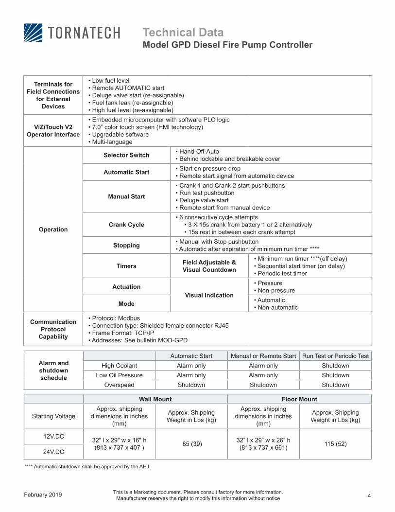
• Low fuel level• Remote AUTOMATIC start• Deluge valve start (re-assignable)• Fuel tank leak (re-assignable) • High fuel level (re-assignable)
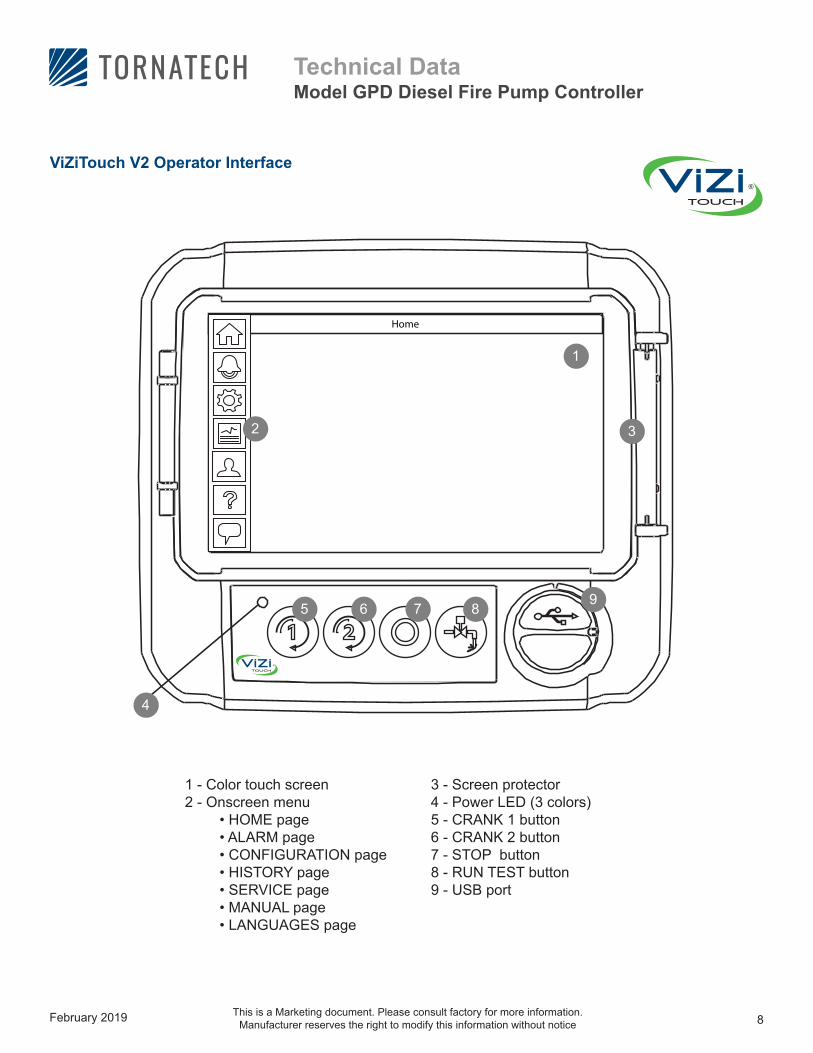
ViZiTouch V2 Operator Interface
• Embedded microcomputer with software PLC logic• 7.0” color touch screen (HMI technology)• Upgradable software• Multi-language
Operation
Selector Switch • Hand-Off-Auto• Behind lockable and breakable cover
Automatic Start • Start on pressure drop• Remote start signal from automatic device
Manual Start
• Crank 1 and Crank 2 start pushbuttons• Run test pushbutton• Deluge valve start• Remote start from manual device
Crank Cycle• 6 consecutive cycle attempts
• 3 X 15s crank from battery 1 or 2 alternatively• 15s rest in between each crank attempt
Stopping • Manual with Stop pushbutton• Automatic after expiration of minimum run timer ****
Timers Field Adjustable & Visual Countdown
• Minimum run timer ****(off delay)• Sequential start timer (on delay)• Periodic test timer
ActuationVisual Indication
• Pressure• Non-pressure
Mode • Automatic• Non-automatic
Communication Protocol
Capability
• Protocol: Modbus• Connection type: Shielded female connector RJ45• Frame Format: TCP/IP• Addresses: See bulletin MOD-GPD
**** Automatic shutdown shall be approved by the AHJ.
Alarm and shutdown schedule
Automatic Start Manual or Remote Start Run Test or Periodic TestHigh Coolant Alarm only Alarm only Shutdown
Low Oil Pressure Alarm only Alarm only ShutdownOverspeed Shutdown Shutdown Shutdown
Wall Mount Floor Mount
Starting VoltageApprox. shipping
dimensions in inches (mm)
Approx. Shipping Weight in Lbs (kg)
Approx. shipping dimensions in inches
(mm)
Approx. Shipping Weight in Lbs (kg)
12V.DC 32" l x 29" w x 16" h (813 x 737 x 407 ) 85 (39) 32” l x 29” w x 26” h
(813 x 737 x 661) 115 (52)24V.DC
February 2019 5
Technical DataModel GPD Diesel Fire Pump Controller
This is a Marketing document. Please consult factory for more information. Manufacturer reserves the right to modify this information without notice
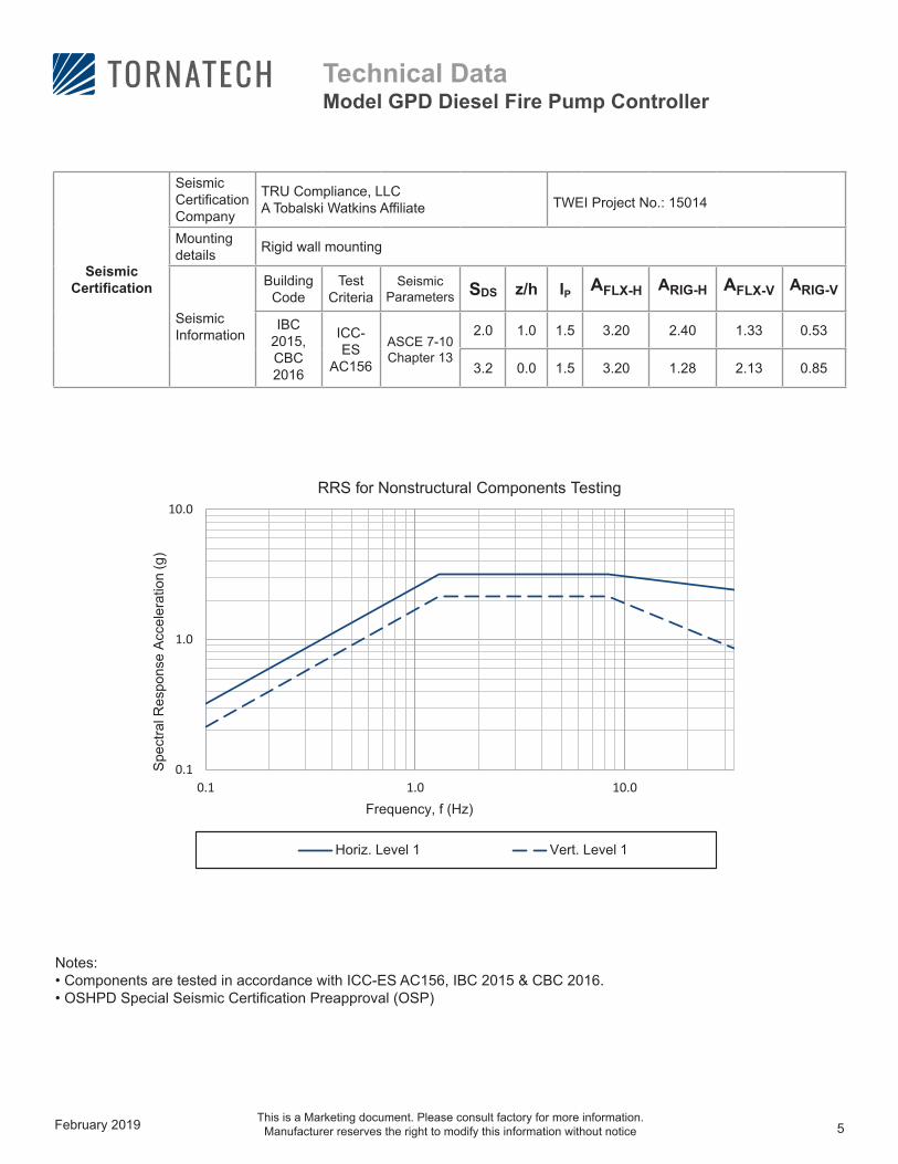
Seismic Certification
Seismic Certification Company
TRU Compliance, LLCA Tobalski Watkins Affiliate TWEI Project No.: 15014
Mounting details Rigid wall mounting
Seismic Information
Building Code
Test Criteria
Seismic Parameters SDS z/h IP AFLX-H ARIG-H AFLX-V ARIG-V
IBC 2015, CBC 2016
ICC-ES
AC156
ASCE 7-10 Chapter 13
2.0 1.0 1.5 3.20 2.40 1.33 0.53
3.2 0.0 1.5 3.20 1.28 2.13 0.85
0.1
1.0
10.0
0.1 1.0 10.0
Spe
ctra
l Res
pons
e A
ccel
erat
ion
(g)
Frequency, f (Hz)
RRS for Nonstructural Components Testing
Horiz. Level 1 Vert. Level 1
Notes:• Components are tested in accordance with ICC-ES AC156, IBC 2015 & CBC 2016. • OSHPD Special Seismic Certification Preapproval (OSP)
February 2019 6
Technical DataModel GPD Diesel Fire Pump Controller
This is a Marketing document. Please consult factory for more information. Manufacturer reserves the right to modify this information without notice
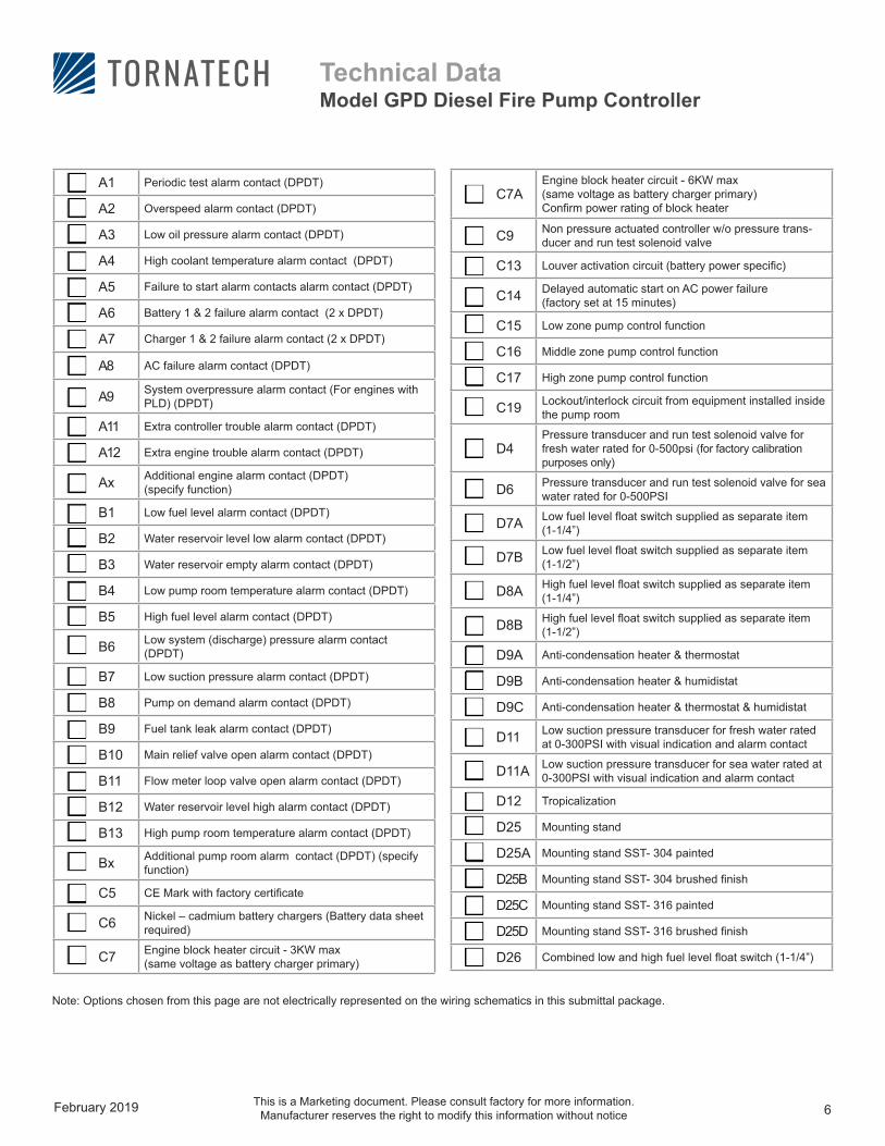
C7AEngine block heater circuit - 6KW max(same voltage as battery charger primary) Confirm power rating of block heater
C9 Non pressure actuated controller w/o pressure trans-ducer and run test solenoid valve
C13 Louver activation circuit (battery power specific)
C14 Delayed automatic start on AC power failure (factory set at 15 minutes)
C15 Low zone pump control function
C16 Middle zone pump control function
C17 High zone pump control function
C19 Lockout/interlock circuit from equipment installed inside the pump room
D4Pressure transducer and run test solenoid valve for fresh water rated for 0-500psi (for factory calibration purposes only)
D6 Pressure transducer and run test solenoid valve for sea water rated for 0-500PSI
D7A Low fuel level float switch supplied as separate item (1-1/4”)
D7B Low fuel level float switch supplied as separate item (1-1/2”)
D8A High fuel level float switch supplied as separate item (1-1/4”)
D8B High fuel level float switch supplied as separate item (1-1/2”)
D9A Anti-condensation heater & thermostat
D9B Anti-condensation heater & humidistat
D9C Anti-condensation heater & thermostat & humidistat
D11 Low suction pressure transducer for fresh water rated at 0-300PSI with visual indication and alarm contact
D11A Low suction pressure transducer for sea water rated at 0-300PSI with visual indication and alarm contact
D12 Tropicalization
D25 Mounting stand
D25A Mounting stand SST- 304 painted
D25B Mounting stand SST- 304 brushed finish
D25C Mounting stand SST- 316 painted
D25D Mounting stand SST- 316 brushed finish
D26 Combined low and high fuel level float switch (1-1/4”)
Note: Options chosen from this page are not electrically represented on the wiring schematics in this submittal package.
A1 Periodic test alarm contact (DPDT)
A2 Overspeed alarm contact (DPDT)
A3 Low oil pressure alarm contact (DPDT)
A4 High coolant temperature alarm contact (DPDT)
A5 Failure to start alarm contacts alarm contact (DPDT)
A6 Battery 1 & 2 failure alarm contact (2 x DPDT)
A7 Charger 1 & 2 failure alarm contact (2 x DPDT)
A8 AC failure alarm contact (DPDT)
A9 System overpressure alarm contact (For engines with PLD) (DPDT)
A11 Extra controller trouble alarm contact (DPDT)
A12 Extra engine trouble alarm contact (DPDT)
Ax Additional engine alarm contact (DPDT) (specify function)
B1 Low fuel level alarm contact (DPDT)
B2 Water reservoir level low alarm contact (DPDT)
B3 Water reservoir empty alarm contact (DPDT)
B4 Low pump room temperature alarm contact (DPDT)
B5 High fuel level alarm contact (DPDT)
B6 Low system (discharge) pressure alarm contact (DPDT)
B7 Low suction pressure alarm contact (DPDT)
B8 Pump on demand alarm contact (DPDT)
B9 Fuel tank leak alarm contact (DPDT)
B10 Main relief valve open alarm contact (DPDT)
B11 Flow meter loop valve open alarm contact (DPDT)
B12 Water reservoir level high alarm contact (DPDT)
B13 High pump room temperature alarm contact (DPDT)
Bx Additional pump room alarm contact (DPDT) (specify function)
C5 CE Mark with factory certificate
C6 Nickel – cadmium battery chargers (Battery data sheet required)
C7 Engine block heater circuit - 3KW max(same voltage as battery charger primary)
February 2019 7
Technical DataModel GPD Diesel Fire Pump Controller
This is a Marketing document. Please consult factory for more information. Manufacturer reserves the right to modify this information without notice
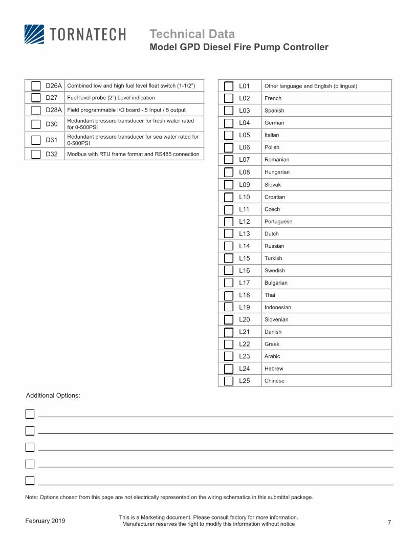
D26A Combined low and high fuel level float switch (1-1/2”)
D27 Fuel level probe (2”) Level indication
D28A Field programmable I/O board - 5 Input / 5 output
D30 Redundant pressure transducer for fresh water rated for 0-500PSI
D31 Redundant pressure transducer for sea water rated for 0-500PSI
D32 Modbus with RTU frame format and RS485 connection
Note: Options chosen from this page are not electrically represented on the wiring schematics in this submittal package.
Additional Options:
L01 Other language and English (bilingual)
L02 French
L03 Spanish
L04 German
L05 Italian
L06 Polish
L07 Romanian
L08 Hungarian
L09 Slovak
L10 Croatian
L11 Czech
L12 Portuguese
L13 Dutch
L14 Russian
L15 Turkish
L16 Swedish
L17 Bulgarian
L18 Thai
L19 Indonesian
L20 Slovenian
L21 Danish
L22 Greek
L23 Arabic
L24 Hebrew
L25 Chinese
February 2019 8
Technical DataModel GPD Diesel Fire Pump Controller
This is a Marketing document. Please consult factory for more information. Manufacturer reserves the right to modify this information without notice
Home
®
4
1
9
32
5 6 7 8
PMS 295 PMS 361 Noir
®
ViZiTouch V2 Operator Interface
3 - Screen protector 4 - Power LED (3 colors) 5 - CRANK 1 button6 - CRANK 2 button7 - STOP button8 - RUN TEST button9 - USB port
1 - Color touch screen2 - Onscreen menu • HOME page • ALARM page • CONFIGURATION page • HISTORY page • SERVICE page • MANUAL page • LANGUAGES page
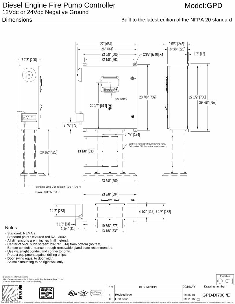
DimensionsBuilt to the latest edition of the NFPA 20 standard
DD/MM/YYDESCRIPTIONREV. Drawing number
Diesel Engine Fire Pump ControllerModel:GPD
DI700 /E
12Vdc or 24Vdc Negative Ground
Drawing for information only.
Manufacturer reserves the right to modify this drawing without notice.
Contact manufacturer for "As Built" drawing.
GPD-
- Controller standard without mounting stand.
- Order option D25 if mounting stand required.
Projection
Notes:
- Protect equipment against drilling chips.
- Door swing equal to door width.
- Use watertight conduit and connector only.
- Bottom conduit entrance through removable gland plate recommended.
- Standard paint : textured red RAL 3002.
- All dimensions are in inches [millimeters].
- Standard:
- Center of ViZiTouch screen: 20-1/4" [514] from bottom (no feet).
See Notes
Sensing Line Connection - 1/2 " F.NPT
Drain - 3/8 " M.TUBE
NYC
Dpt of Building
Approved
- Seismic mounting to be rigid wall only.
2018Copyright © Tornatech Inc.
All right reserved. This drawing and the information contained or depicted herein are the sole property of Tornatech Inc. Copies are communicated to the recipient in strict confidence and may not be retransmitted, published, reproduced, copied or used in any manner, including as the basis for the manufacture or sale of any products, without the express prior written consent of Tornatech Inc.
CDL
0. First issue 18/11/16
NEMA 2
22 1/8" [562]
23 5/8" [600]
26" [661]
27" [684]
Ø3/8" [Ø10] X4
28 7/8" [732]
9 5/8" [245]
8 5/8" [220]
1/2" [12]
27 1/2" [700]
29 7/8" [757]
2 7/8" [73]
23 3/8" [594]
10 7/8" [275]
13 1/8" [333]
4 1/2" [115] 7 1/8" [182]
23 5/8" [600]
6 7/8" [174]
13 1/8" [333]
7 7/8" [200]
20 1/4" [514]
1.
Revised logo
18/06/18
PT1
SV1
20 1/2" [520]
1 1/4" [31]
3 1/3" [84]
9 1/6" [233]
I/O
DI5
CO
M
DI4
VMB1
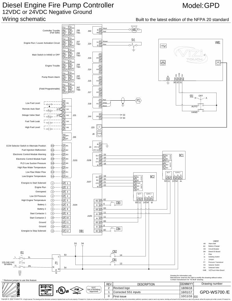
Wiring schematic Built to the latest edition of the NFPA 20 standard
DD/MM/YYDESCRIPTIONREV.NYC
Dpt of Building
Approved
Drawing number
Diesel Engine Fire Pump ControllerModel:GPD
CB1
CB2
14
13
53
54
L
N
N'
L'
E
120-240 VAC
50-60Hz
12VDC or 24VDC Negative Ground
WS700 /EGPD-
1N
1L
CDL
2018Copyright © Tornatech Inc.
All right reserved. This drawing and the information contained or depicted herein are the sole property of Tornatech Inc. Copies are communicated to the recipient in strict confidence and may not be retransmitted, published, reproduced, copied or used in any manner, including as the basis for the manufacture or sale of any products, without the express prior written consent of Tornatech Inc.
0
First issue10/11/16
IS1
J37
J38
J39
J40
J42
PT1
Black
Red
White
J25
IN1
TB2
TB3
TB4
TB5
TB6
C
NC
NO
C
NC
NO
J36
TB1
IN2
IN3
IN4
IN5
J16
AI5
-
+
J14
AI4
-
+
J15
AI3
-
+
J17
AI2
-
+
J44
DOWN
AB1
- +Black
Red
DB1
UP
J20
J8
1
2
C
NC
NO
C
NC
NO
1
2
C
NC
NO
C
NC
NO
1
2
C
NC
NO
C
NC
NO
1
2
C
NC
NO
C
NC
NO
1
2
C
NC
NO
C
NC
NO
1
2
MP-
MP+
J103
302
301
304
303
310
305
312
311
J35
1
2
3
4
5
6
8
9
10
11
12
1
3
4
5
2
6
8
9
10
11
12
1111
Energize to Start Solenoid
Engine Run
Overspeed
Low Oil Pressure
High Engine Temperature
Start Contactor 1
Ground
Start Contactor 2
Ground
Energize to Stop Solenoid
Battery 1
Battery 2
J104
J50
AB
J24
SV
J18
AI1
-
+
VIN
J4
24V in
24V out
J106
B1-
B1+
CF1
J107
B2-
B2+
CF2
82
8
83
63
6
62
J105
(Field Programmable)
Pump Room Alarm
Engine Trouble
Main Switch in HAND or OFF
Engine Run / Louver Activation Circuit
Controller Trouble
(Fail Safe)
Low Fuel Level
Remote Auto Start
Deluge Valve Start
Fuel Tank Leak
High Fuel Level
J1*
J2*
F1
53
53
54
CB3
CB4
8
82
62
6
63
11
11
83
BC1
NO
B2
-
BATT.
+
B1
Com
NC
L N
SUPPLY
BC2
NO
ALA
RM
B2
BO
OS
T
-
BATT.
+
B1
Com
NC
L N
SUPPLY
H
OFF
A
SS1
AUTO
HAND
15
16
17
18
19
20
21
22
ALA
RM
BO
OS
T
54
30 32 31
83 11 14 54
63 11 13 54
Drawing for information only.
Manufacturer reserves the right to modify this drawing without notice.
Contact manufacturer for "As Built" drawing.
ECM Selector Switch in Alternate Position
Fuel Injection Malfunction
Electronic Control Module Warning
Electronic Control Module Fault
Low Engine Temperature
301
302
303
304
305
310
311
312
PLD Low Suction Pressure
High Raw Water Temperature
Low Raw Water Flow
SV1
Blue
Brown
* Remove jumper to use this feature
Legend
AB Alarm Bell
BC
Battery Charger
CB Circuit Breaker
DB Diesel I/O Board
F Filter
IS
Isolating Switch
J
Jumper
PT Pressure Transducer
SS Selector Switch
SV Solenoid Valve
VMB ViZiTouch Main Board
1 Corrected SS1 inputs 16/01/17
2 Revised logo 18/06/18
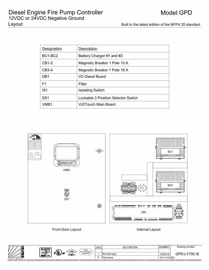
DescriptionDesignation
Internal Layout
SS1
VMB1
Front Door Layout
Layout
DD/MM/YYDESCRIPTIONREV. Drawing number
Model:GPD
LY700 /EGPD-0 First issue 21/11/16 CDL
BC2
BC1
0 - OFF
IS1
F1540 - OFF0 - OFF 0 - OFF
Built to the latest edition of the NFPA 20 standard
Diesel Engine Fire Pump Controller12VDC or 24VDC Negative Ground
IN1
C NC
NO
C NC
NO
IN2
IN3
IN4
IN5
12
C NC
NO
C NC
NO
12
C NC
NO
C NC
NO
12
C NC
NO
C NC
NO
12
C NC
NO
C NC
NO
12
C NC
NO
C NC
NO
12
MP
-
MP+
302
301
304
303
310
305
312
311 1 2 3 4 5 6 8 9 10 11 1211
AI5 -+
AI4 -+
AI3 -+
AI2 -+ D
OW
N
UP
AB
SV
AI1 -+
VIN
24V
in
24V
out
B1-
B1+
CF1 B2-
B2+
CF2 8288363662
DB1
NYCDpt of Building
Approved
BC1-BC2 Battery Charger #1 and #2
CB1-2 Magnetic Breaker 1 Pole 10 A
CB3-4 Magnetic Breaker 1 Pole 16 A
DB1 I/O Diesel Board
F1 FilterIS1 Isolating Switch
SS1 Lockable 3 Position Selector Switch
VMB1 ViZiTouch Main Board
1 Revised logo 18/06/18
All wiring between the controller and diesel engine shall be stranded(NFPA20)
Wiring between controller and engine (terminals 301, 302, 303, 304, 305,310, 311, 312, 2 ,3 ,4 ,5) must be #14AWG as minimum.
DD/MM/YYDESCRIPTIONREV. Drawing number
Model:GPD
TD700 /EGPD-
1
2
3
4
5
6
8
9
10
11
12
1
3
4
5
2
9
10
11
12
301
302
J104
303
304
312
1111
50-60Hz
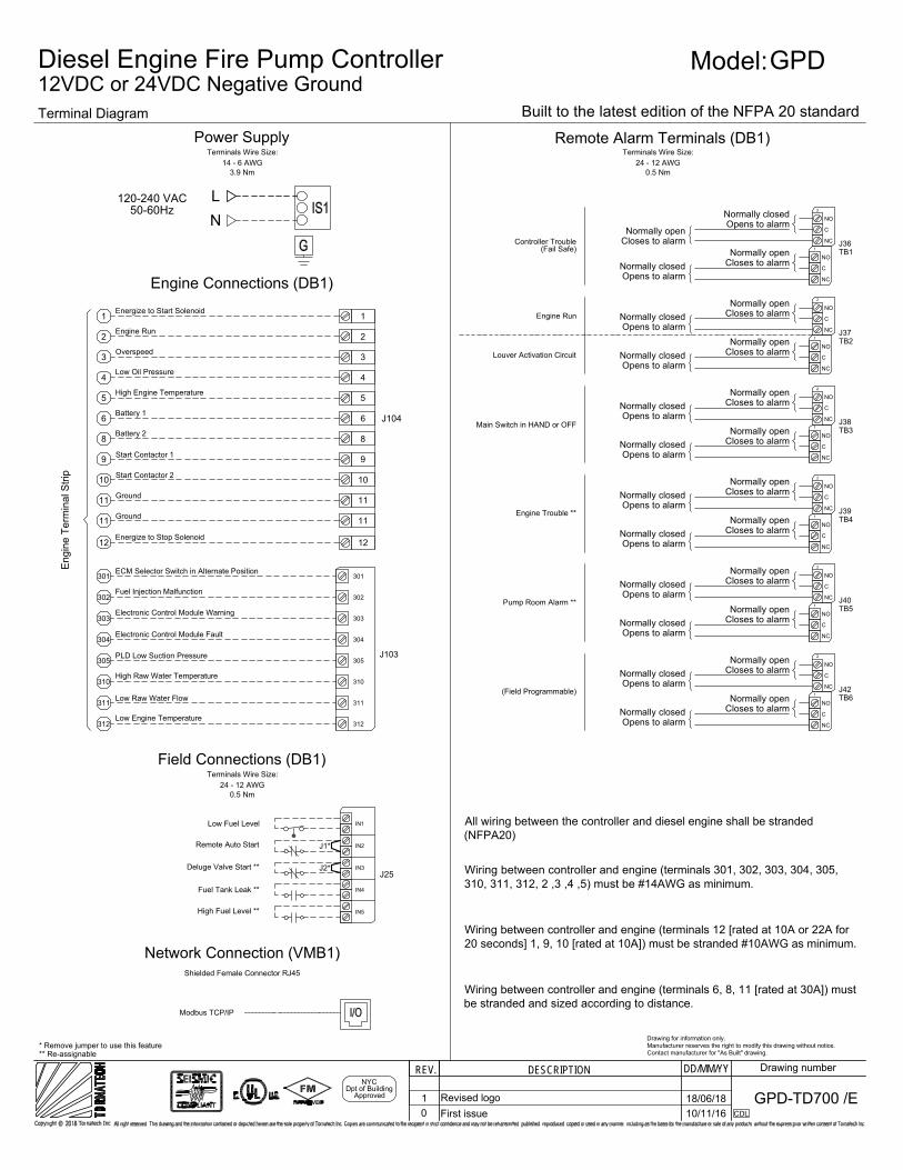
3.9 Nm14 - 6 AWG
Power SupplyTerminals Wire Size:
120-240 VAC
Engine Connections (DB1)
6
8
Engi
ne T
erm
inal
Stri
p
0.5 Nm24 - 12 AWG
Terminals Wire Size:
J25
301
J103
302
303
304
305
310
311
312
305
310
311
0.5 Nm24 - 12 AWG
Field Connections (DB1)Terminals Wire Size:
Wiring between controller and engine (terminals 12 [rated at 10A or 22A for20 seconds] 1, 9, 10 [rated at 10A]) must be stranded #10AWG as minimum.
Wiring between controller and engine (terminals 6, 8, 11 [rated at 30A]) mustbe stranded and sized according to distance.
NL
0 First issue 10/11/16 CDL
Built to the latest edition of the NFPA 20 standard
Diesel Engine Fire Pump Controller12VDC or 24VDC Negative GroundTerminal Diagram
Drawing for information only.Manufacturer reserves the right to modify this drawing without notice.Contact manufacturer for "As Built" drawing.
Energize to Start Solenoid
Engine Run
Overspeed
Low Oil Pressure
High Engine Temperature
Start Contactor 1
Ground
Start Contactor 2
Ground
Energize to Stop Solenoid
Battery 1
Battery 2
ECM Selector Switch in Alternate Position
Fuel Injection Malfunction
Electronic Control Module Warning
Electronic Control Module Fault
Low Engine Temperature
PLD Low Suction Pressure
High Raw Water Temperature
Low Raw Water Flow
IN1
IN2
IN3
IN4
IN5
Low Fuel Level
Remote Auto Start
Deluge Valve Start **
Fuel Tank Leak **
High Fuel Level **
J1*
J2*
** Re-assignable* Remove jumper to use this feature
Remote Alarm Terminals (DB1)
C
NC
NO
C
NC
NO
1
2
J36TB1
C
NC
NO
C
NC
NO
1
2
J37TB2
C
NC
NO
C
NC
NO
1
2
Normally closedOpens to alarm
Closes to alarmNormally open
J38TB3
Normally closedOpens to alarm
Closes to alarmNormally open
C
NC
NO
C
NC
NO
1
2
Normally closedOpens to alarm
Closes to alarmNormally open
J39TB4
Normally closedOpens to alarm
Closes to alarmNormally open
C
NC
NO
C
NC
NO
1
2
Normally closedOpens to alarm
Closes to alarmNormally open
J40TB5
Normally closedOpens to alarm
Closes to alarmNormally open
C
NC
NO
C
NC
NO
1
2
Normally closedOpens to alarm
Closes to alarmNormally open
J42TB6
Normally closedOpens to alarm
Closes to alarmNormally open
Controller Trouble(Fail Safe)
Louver Activation Circuit
Engine Run
Main Switch in HAND or OFF
Engine Trouble **
Pump Room Alarm **
(Field Programmable)
Normally closedOpens to alarm
Closes to alarmNormally open
Normally closedOpens to alarm
Closes to alarmNormally open
Normally closedOpens to alarm
Closes to alarmNormally open
Normally closedOpens to alarm
Closes to alarmNormally open
Modbus TCP/IP
Network Connection (VMB1)Shielded Female Connector RJ45
NYCDpt of Building
Approved 1 Revised logo 18/06/18
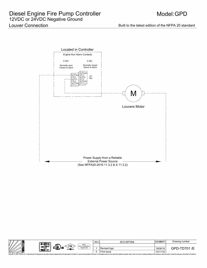
Louver Connection
DD/MM/YYDESCRIPTIONREV. Drawing number
Model:GPD
TD701 /EGPD-
M
Engine Run Alarm Contacts
Normally openCloses to alarm
Normally closedOpens to alarm
C-NO C-NC
Power Supply from a ReliableExternal Power Source
(See NFPA20-2016 11.3.2 & A 11.3.2)
Louvers Motor
J37TB2
Located in Controller
NO
C
NC
NO
C
NC
0 First issue 10/11/16
Built to the latest edition of the NFPA 20 standard
Diesel Engine Fire Pump Controller12VDC or 24VDC Negative Ground
NYCDpt of Building
Approved 1 Revised logo 18/06/18


![Chap09[2] LS Modif](https://img.pdfslide.us/doc/110x75/577ce4bb1a28abf1038f0760/chap092-ls-modif.jpg)
