Embed Size (px)
Citation preview
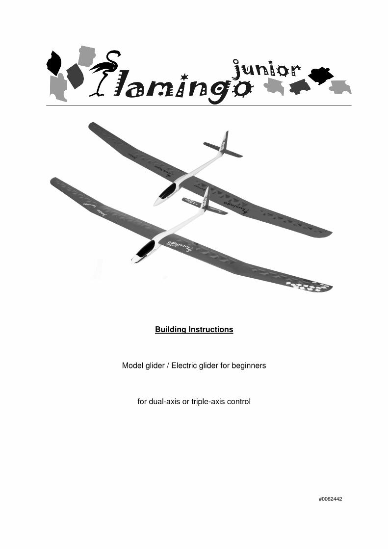
Building Instructions
Model glider / Electric glider for beginners
for dual-axis or triple-axis control
#0062442
Graupner GmbH & Co. KG * Henriettenstraße 94-96 * 73230 Kirchheim * www. Graupner. de – www. Tangent–Modelltechnik.com
2
Contents Introduction Kit contents Specification RC functions Note: gluing with epoxy Fuselage and tail Fuselage openings Installing the tow-hook Installing the canopy latch The tailplane clamp Completing the fin and rudder Installing the servo plate - glider version Completing the control surface linkages in the fuselage Electric version Battery support Installing the servo plate (electric) Installing the receiving system - glider version
Installing the servos in the fuselage Installing the On / Off switch Installing the receiver Installing the battery Installing the receiving system - electric version
Installing the motor Installing the speed controller Installing the battery Installing the receiver Installing the servos in the fuselage
Wings Fuselage / wing transition Preparing the wings for triple-axis control (ailerons)
Installing working ailerons Installing the aileron servos Installing the aileron horns
Setting the wing dihedral Electrical connections The finish Deploying the aerial(s) For 35 MHz operation For 2.4GHz operation
Graupner GmbH & Co. KG * Henriettenstraße 94-96 * 73230 Kirchheim * www. Graupner. de – www. Tangent–Modelltechnik.com
3
Setting-up Centre of Gravity and longitudinal dihedral Control surface settings (normal flying, landing) The first flight Test-flying Range-checking
For 35 MHz operation For 2.4 GHz operation
The first flight Flat-field flying Flying at the slope Safety, the fascination of it all Appendix
Recommended RC equipment Parts list, pictures, sketches
Graupner GmbH & Co. KG * Henriettenstraße 94-96 * 73230 Kirchheim * www. Graupner. de – www. Tangent–Modelltechnik.com
4
Beginner’s model, with or without electric power system Flamingo Junior ARF glider # 41545 Flamingo Junior ARF electric # 41555
Introduction
Dear fellow-modeller, We are delighted that you have decided to build our Flamingo Junior model glider, and we are con-fident that you will have many hours or pleasure and success with this small fun-model. TANGENT model kits from the GRAUPNER stable are sophisticated designs, and are the result of many years of practical experience. With these products you obtain far more than just a model: you benefit from con-sistent long-term product maintenance, standardised production techniques and carefully managed quality, and this is your guarantee of a reliable product and the highest quality of service over a period of many years. Although we carry out conscientious quality control procedures, it is always possible that kit com-ponents will exhibit minor deviations or imperfections. We therefore ask you to check all components before use, as we cannot exchange parts which you have already modified. If any component is not satisfactory, we will gladly correct the fault or replace it after checking. Please send the component to our Service department together with the completed complaints return form, and be sure to include a brief description of the defect. We are constantly working on the technical development of our models, and for this reason we must reserve the right to alter the kit contents in terms of shape, dimensions, technology, materials and features. Please understand that we cannot entertain claims based on statements and illustrations in these instructions.
Important safety notes during construction You have acquired a kit which can be assembled into a fully working RC model when fitted out with suitable accessories. However, we as manufacturers have no control over the way you build and fly your RC model aircraft, nor how you install, operate and maintain the associated components, and for this reason we are obliged to deny all liability for loss, damage or costs which are incurred due to the incompetent or incorrect use and operation of our products, or which are connected with such operation in any way. Unless otherwise prescribed by binding law, the obligation of the GRAUPNER company to pay compensation, regardless of the legal argument employed, is excluded. This includes personal injury, death, damage to buildings, damage due to loss of business or turnover, interruption of business or other direct or indirect consequent damage whose root cause was the operation of the model. Our total liability in all cases is limited to the amount of money which you actually paid for this model.
This model aeroplane is built and flown at the sole and express responsibility of the operator. The only way to avoid injury to persons and damage to property is to handle and operate the model with the greatest care and consideration at all times.
When handling adhesives and solvent-based materials it is important to observe the safety notes and instructions supplied by the manufacturer. Many glues and solvents are capable of causing injury and damage to materials if they are not used competently. Take waste glue and paint to your local model shop or toxic waste collection centre. Note that balsa knives, pins, etc. have sharp points and edges, and should be handled carefully to avoid injury. Take care to keep tools, adhesives and paints out of the reach of children. A large, unob-structed working surface is a great advantage for all types of model-making. If you are a relative beginner and are not sure of any process, it is always best to ask an experienced modeller for help.
Graupner GmbH & Co. KG * Henriettenstraße 94-96 * 73230 Kirchheim * www. Graupner. de – www. Tangent–Modelltechnik.com
5
Flying the model Never fly your Flamingo Junior in a nature reserve or any other protected site. Please don’t disturb the animals and plants which live in the countryside. Trees and bushes are the natural habitat of many birds, and also serve as nesting sites and general protection for them. Before you fly the model for the first time it is essential to take out a special insurance policy designed to cover modelling risks. These safety notes should be kept in a safe place. If you ever dispose of the model, be sure to pass them on to the new owner. Manufacturer’s declaration: If material defects or manufacturing faults should arise in a product distributed by us in the Federal Republic of Germany and purchased by a consumer (§ 13 BGB), we, Graupner GmbH & Co. KG, D-73230 Kirchheim/Teck, Germany, acknowledge the obligation to correct those defects within the limitations described below. The consumer is not entitled to exploit this manufacturer’s declaration if the failure in the usability of the product is due to natural wear, use under competition conditions, incompetent or improper use (including incorrect installation) or external influences. This manufacturer’s declaration does not affect the consumer’s legal or contractual rights regarding defects arising from the purchase contract between the consumer and the vendor (dealer). Extent of the guarantee: If a claim is made under guarantee, we undertake at our discretion to repair or replace the defective goods. We will not consider supplementary claims, especially for reimbursement of costs relating to the defect (e.g. installation / removal costs) and compensation for consequent damages unless they are allowed by statute. This does not affect claims based on legal regulations, especially according to product liability law. Guarantee requirements: The purchaser is required to make the guarantee claim in writing, and must enclose original proof of purchase (e.g. invoice, receipt, delivery note) and this guarantee card. He must send the defective goods to us at his own cost, using the address stated above. The purchaser should state the material defect or manufacturing fault, or the symptoms of the fault, in as accurate a manner as possible, so that we can check if our guarantee obligation is applicable. The goods are transported from the consumer to us and from us to the consumer at the risk of the consumer. Duration of validity: This declaration only applies to claims made to us during the claim period as stated in this declaration. The claim period is 24 months from the date of purchase of the product by the consumer from a dealer in the Federal Republic of Germany (date of purchase). If a defect arises after the end of the claim period, or if the evidence or documents required according to this declaration in order to make the claim valid are not presented until after this period, then the consumer forfeits any rights or claims from this declaration. Limitation by lapse of time: If we do not acknowledge the validity of a claim based on this declaration within the claim period, all claims based on this declaration are barred by the statute of limitations after six months from the time of implementation; however, this cannot occur before the end of the claim period. Applicable law: This declaration, and the claims, rights and obligations arising from it, are based exclusively on the pertinent German Law, without the norms of international private law, and excluding UN retail law.
Graupner GmbH & Co. KG * Henriettenstraße 94-96 * 73230 Kirchheim * www. Graupner. de – www. Tangent–Modelltechnik.com
6
The following points are important and must be observed at all times:
• Before you fly the model check that the radio control system is working reliably, and that all connections are secure.
• The batteries must be charged and the range of the radio control system must be checked before you operate the model. In particular, the radio control system batteries must be fully charged before each session.
• Ensure that the channel you intend to use is not already in use by other modellers. Never fly the aeroplane if you are not certain that your channel is free.
• Read and observe the instructions and recommendations provided by the manufacturer of your radio control system and accessory components.
• Ensure that the servos are not mechanically obstructed at any point in their travel.
• Dry cells and rechargeable batteries must never be short-circuited.
• Remove all batteries from the model prior to transporting and storing it.
• Do not subject the aircraft to dirty or cold conditions, or high levels of humidity or heat.
• Secure the model and your RC equipment carefully when transporting them. They may be seriously damaged if they are free to slide about.
• Important: when the flight battery is exhausted, you must not dispose of it in the household waste. Take the pack to your local battery reclamation centre.
• Important: when the useful life of the model and the transmitter are over, do not discard them in the domestic rubbish. The electric and electronic components in particular must be taken to your nearest electrical recycling centre. Ask your local authority if you are not sure of its location.
Kit contents 1 Pair of wings, film-covered, with window lightening technology and 3D wingtips, ailerons prepared for triple-axis control, factory-fitted joiner system incorporated into full-depth spar, Multi-Wing wing retainer system 1 GRP fuselage, pure white finish, with Multi-Wing wing retainer system, factory-fitted all-moving tail-plane bellcrank, pre-fitted tail post, factory-installed control snake sleeves (electric version: motor bulk-head installed) 1 Set of tailplane panels with installed joiner tubes and 3D tips 1 Rudder 1 Set of laser-cut wooden parts for RC installation 1 Bag of high-quality CONTESTLINE accessories
Specification, RC functions Specification: Wingspan approx. 2250 mm Fuselage length 990 mm Wing area 35 dm² Weight min. 1250 g (glider) min. 1450 g (electric) Wing section CY – 11 % Longitudinal dihedral approx. 2° Centre of Gravity approx. 60 - 65 mm
RC functions, glider version Rudder, elevator, (optional) ailerons RC functions, electric version Rudder, elevator, throttle, (optional) ailerons
Graupner GmbH & Co. KG * Henriettenstraße 94-96 * 73230 Kirchheim * www. Graupner. de – www. Tangent–Modelltechnik.com
7
Notes on adhesives It is essential to avoid using solvent-based glues for any joint in which the adhesive comes into contact with the styrofoam wing core. This applies in particular to cyano-acrylates, as these materials im-mediately attack the foam and cause large-scale damage; in most cases the component is rendered unusable. Use only solvent-free adhesives; we recommend UHU plus Endfest (slow-setting epoxy resin) or epoxy laminating resin thickened with chopped cotton strands. Do not use 5-minute epoxy for joints which are vital to airframe integrity, or for crucial control linkages! Epoxy laminating resin is not an effective adhesive on its own. These resins only work well as glues when thickened with various additives. You can adjust the qualities of your adhesive by choosing the appropriate additive to suit your application:
1. Chopped cotton strands produce a tough, flexible joint - ideal for highly stressed areas.
2. Super-fine glass fibres produce a rock-solid joint which is easy to sand. An excellent choice for joints which are not subject to severe mechanical stress.
3. Micro-balloons transform epoxy resin into a lightweight filler paste - ideal for areas
where the mechanical stress is low or non-existent.
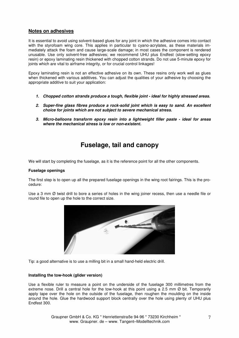
Fuselage, tail and canopy We will start by completing the fuselage, as it is the reference point for all the other components. Fuselage openings The first step is to open up all the prepared fuselage openings in the wing root fairings. This is the pro-cedure: Use a 3 mm Ø twist drill to bore a series of holes in the wing joiner recess, then use a needle file or round file to open up the hole to the correct size.
Tip: a good alternative is to use a milling bit in a small hand-held electric drill. Installing the tow-hook (glider version) Use a flexible ruler to measure a point on the underside of the fuselage 300 millimetres from the extreme nose. Drill a central hole for the tow-hook at this point using a 2.5 mm Ø bit. Temporarily apply tape over the hole on the outside of the fuselage, then roughen the moulding on the inside around the hole. Glue the hardwood support block centrally over the hole using plenty of UHU plus Endfest 300.
Graupner GmbH & Co. KG * Henriettenstraße 94-96 * 73230 Kirchheim * www. Graupner. de – www. Tangent–Modelltechnik.com
8
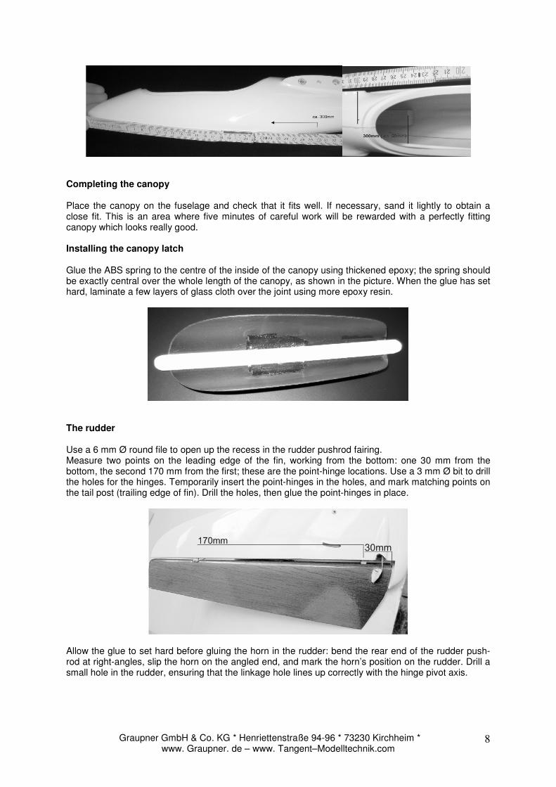
Completing the canopy Place the canopy on the fuselage and check that it fits well. If necessary, sand it lightly to obtain a close fit. This is an area where five minutes of careful work will be rewarded with a perfectly fitting canopy which looks really good. Installing the canopy latch Glue the ABS spring to the centre of the inside of the canopy using thickened epoxy; the spring should be exactly central over the whole length of the canopy, as shown in the picture. When the glue has set hard, laminate a few layers of glass cloth over the joint using more epoxy resin.
The rudder Use a 6 mm Ø round file to open up the recess in the rudder pushrod fairing. Measure two points on the leading edge of the fin, working from the bottom: one 30 mm from the bottom, the second 170 mm from the first; these are the point-hinge locations. Use a 3 mm Ø bit to drill the holes for the hinges. Temporarily insert the point-hinges in the holes, and mark matching points on the tail post (trailing edge of fin). Drill the holes, then glue the point-hinges in place.
Allow the glue to set hard before gluing the horn in the rudder: bend the rear end of the rudder push-rod at right-angles, slip the horn on the angled end, and mark the horn’s position on the rudder. Drill a small hole in the rudder, ensuring that the linkage hole lines up correctly with the hinge pivot axis.
Graupner GmbH & Co. KG * Henriettenstraße 94-96 * 73230 Kirchheim * www. Graupner. de – www. Tangent–Modelltechnik.com
9
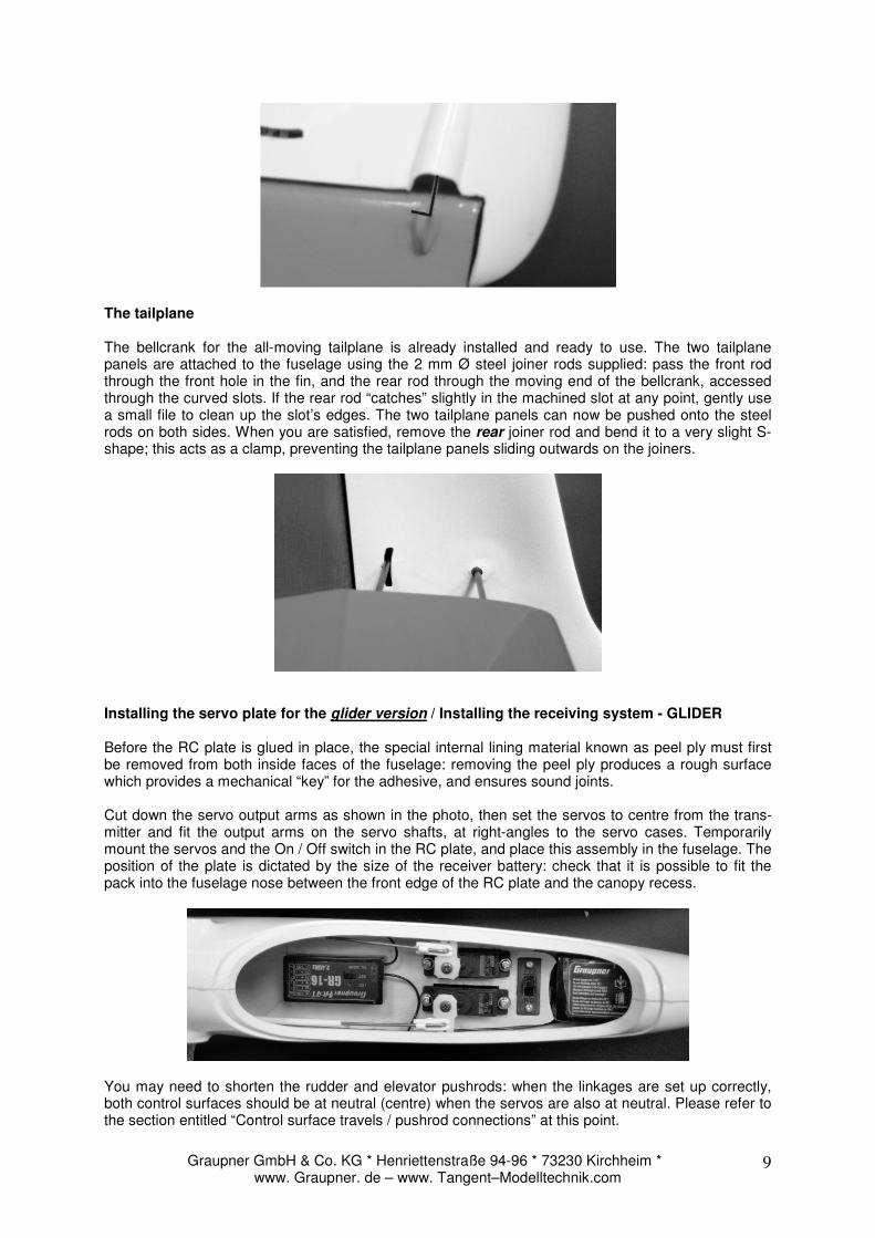
The tailplane The bellcrank for the all-moving tailplane is already installed and ready to use. The two tailplane panels are attached to the fuselage using the 2 mm Ø steel joiner rods supplied: pass the front rod through the front hole in the fin, and the rear rod through the moving end of the bellcrank, accessed through the curved slots. If the rear rod “catches” slightly in the machined slot at any point, gently use a small file to clean up the slot’s edges. The two tailplane panels can now be pushed onto the steel rods on both sides. When you are satisfied, remove the rear joiner rod and bend it to a very slight S-shape; this acts as a clamp, preventing the tailplane panels sliding outwards on the joiners.
Installing the servo plate for the glider version / Installing the receiving system - GLIDER Before the RC plate is glued in place, the special internal lining material known as peel ply must first be removed from both inside faces of the fuselage: removing the peel ply produces a rough surface which provides a mechanical “key” for the adhesive, and ensures sound joints. Cut down the servo output arms as shown in the photo, then set the servos to centre from the trans-mitter and fit the output arms on the servo shafts, at right-angles to the servo cases. Temporarily mount the servos and the On / Off switch in the RC plate, and place this assembly in the fuselage. The position of the plate is dictated by the size of the receiver battery: check that it is possible to fit the pack into the fuselage nose between the front edge of the RC plate and the canopy recess.
You may need to shorten the rudder and elevator pushrods: when the linkages are set up correctly, both control surfaces should be at neutral (centre) when the servos are also at neutral. Please refer to the section entitled “Control surface travels / pushrod connections” at this point.
Graupner GmbH & Co. KG * Henriettenstraße 94-96 * 73230 Kirchheim * www. Graupner. de – www. Tangent–Modelltechnik.com
10
When you are satisfied, tack the servo plate to the fuselage with a few drops of cyano, then remove the servos from the plate. The servo plate can now be glued securely to both sides of the fuselage with a neat fillet of epoxy.
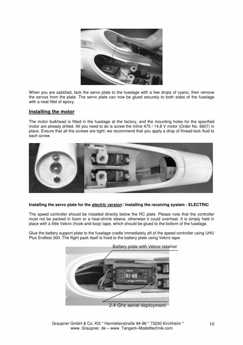
Installing the motor The motor bulkhead is fitted in the fuselage at the factory, and the mounting holes for the specified motor are already drilled. All you need to do is screw the Inline 475 / 14.8 V motor (Order No. 6607) in place. Ensure that all the screws are tight; we recommend that you apply a drop of thread-lock fluid to each screw.
Installing the servo plate for the electric version / Installing the receiving system - ELECTRIC The speed controller should be installed directly below the RC plate. Please note that the controller must not be packed in foam or a heat-shrink sleeve, otherwise it could overheat. It is simply held in place with a little Velcro (hook-and-loop) tape, which should be glued to the bottom of the fuselage. Glue the battery support plate to the fuselage cradle immediately aft of the speed controller using UHU Plus Endfest 300. The flight pack itself is fixed to the battery plate using Velcro tape.
Graupner GmbH & Co. KG * Henriettenstraße 94-96 * 73230 Kirchheim * www. Graupner. de – www. Tangent–Modelltechnik.com
11
Before the RC plate is glued in place, the special internal lining material known as peel ply must first be removed from both inside faces of the fuselage. Removing the peel ply produces a rough surface which provides a mechanical “key” for the adhesive, and ensures sound joints. Cut down the servo output arms as shown in the photo, then set the servos to centre from the trans-mitter and fit the output arms on the servo shafts, at right-angles to the servo cases. The receiver can also be attached to the RC plate aft of the servos using Velcro tape. Temporarily mount the servos in the RC plate, and place this assembly in the fuselage.
You may need to shorten the rudder and elevator pushrods: when the linkages are set up correctly, both control surfaces should be at neutral (centre) when the servos are at neutral. Please refer to the section entitled “Control surface travels / pushrod connections” at this point. When you are satisfied, tack the servo plate to the fuselage with a few drops of cyano, then remove the servos from the plate. The servo plate can now be glued securely to both sides of the fuselage with a neat fillet of epoxy.
Wings
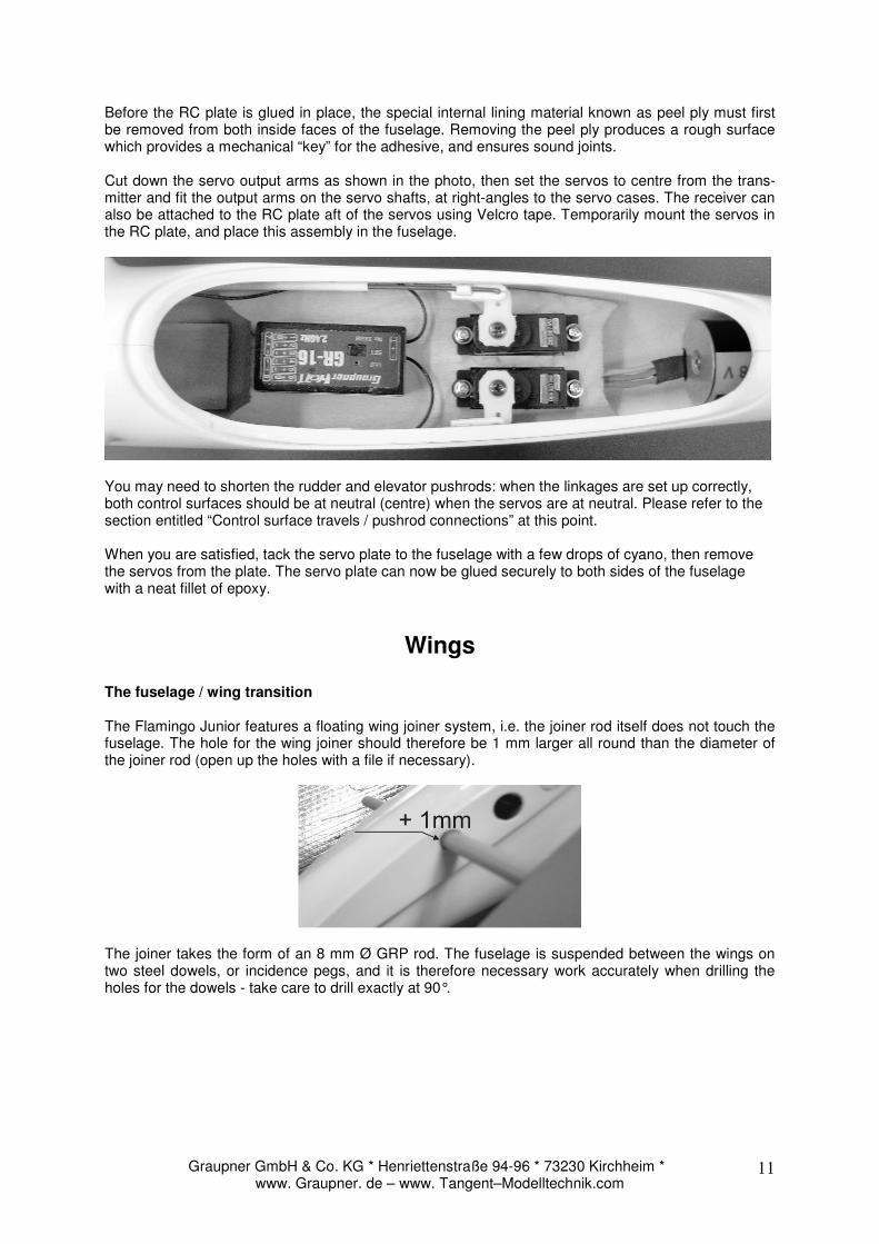
The fuselage / wing transition The Flamingo Junior features a floating wing joiner system, i.e. the joiner rod itself does not touch the fuselage. The hole for the wing joiner should therefore be 1 mm larger all round than the diameter of the joiner rod (open up the holes with a file if necessary).
The joiner takes the form of an 8 mm Ø GRP rod. The fuselage is suspended between the wings on two steel dowels, or incidence pegs, and it is therefore necessary work accurately when drilling the holes for the dowels - take care to drill exactly at 90°.
Graupner GmbH & Co. KG * Henriettenstraße 94-96 * 73230 Kirchheim * www. Graupner. de – www. Tangent–Modelltechnik.com
12
Pilot-holes for the incidence pegs and the Multilock pin are already present in the wing root ribs. Open up the pilot-holes, push the steel dowels and the Multilock pin in the openings, and check that the wings are a snug fit against the fuselage.
Fit the tailplane panels again, and check that the wings line up correctly with the tailplane when viewed from the nose or tail. When you are confident that all is well, the incidence pegs and the Multi-lock can be glued in place. Press the Multilock pins into the Multilock sockets in the fuselage, and mask out the area around the wing retainer with adhesive tape, to prevent glue residues penetrating into the clamp section. Now fill the holes in the wing roots for the incidence pegs and the Multilock pins with thickened epoxy, and push the pegs and the wing retainers in the holes. Fit the wings on the fuselage with the help of the wing joiner, and tape the parts together while the glue sets hard. Tip: use a disposable syringe to fill the holes with resin. Preparing the wings for triple-axis control (ailerons)
1. Installing working ailerons / completing the aileron hinges
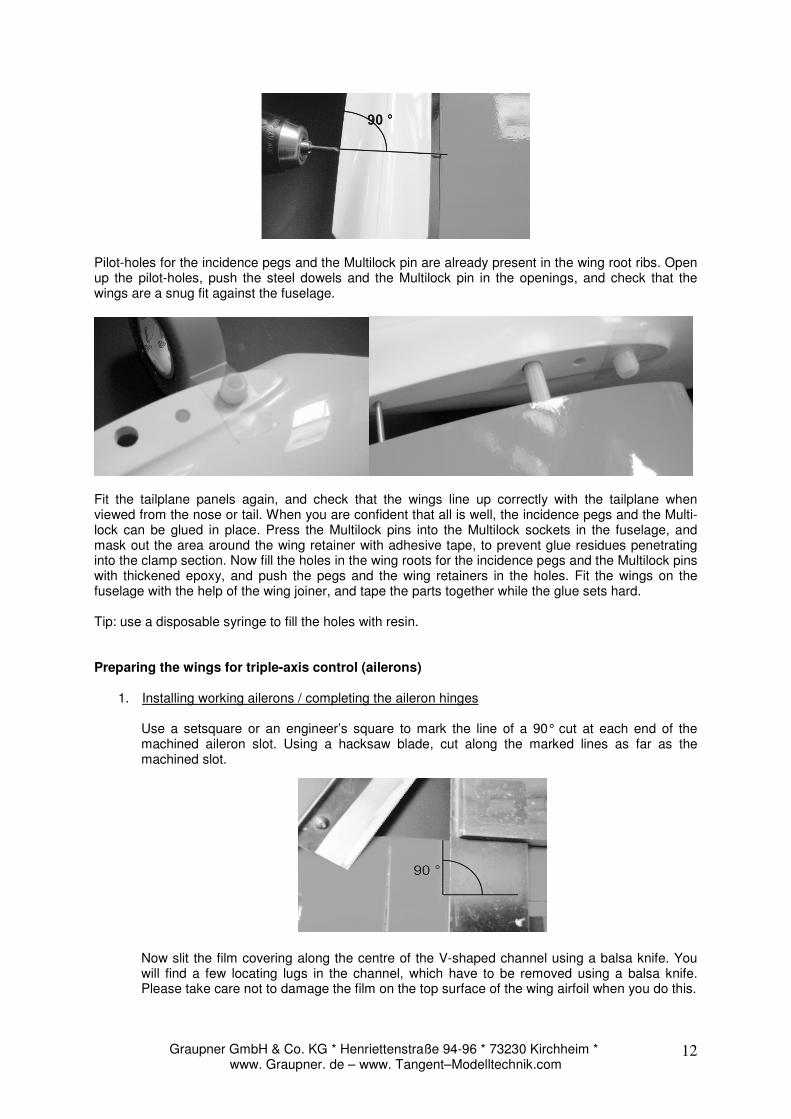
Use a setsquare or an engineer’s square to mark the line of a 90° cut at each end of the machined aileron slot. Using a hacksaw blade, cut along the marked lines as far as the machined slot.
Now slit the film covering along the centre of the V-shaped channel using a balsa knife. You will find a few locating lugs in the channel, which have to be removed using a balsa knife. Please take care not to damage the film on the top surface of the wing airfoil when you do this.
Graupner GmbH & Co. KG * Henriettenstraße 94-96 * 73230 Kirchheim * www. Graupner. de – www. Tangent–Modelltechnik.com
13
Now fold the aileron up as far as it will go, and press the excess film into the machined channel using the back of a knife. The film strips supplied in the kit can now be applied inside the open V-shaped channel to act as a hinge doubler.
2. Installing the aileron servos and horns
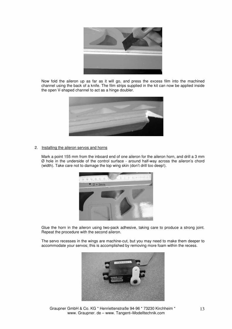
Mark a point 155 mm from the inboard end of one aileron for the aileron horn, and drill a 3 mm Ø hole in the underside of the control surface - around half-way across the aileron’s chord (width). Take care not to damage the top wing skin (don’t drill too deep!).
Glue the horn in the aileron using two-pack adhesive, taking care to produce a strong joint. Repeat the procedure with the second aileron. The servo recesses in the wings are machine-cut, but you may need to make them deeper to accommodate your servos; this is accomplished by removing more foam within the recess.
Graupner GmbH & Co. KG * Henriettenstraße 94-96 * 73230 Kirchheim * www. Graupner. de – www. Tangent–Modelltechnik.com
14
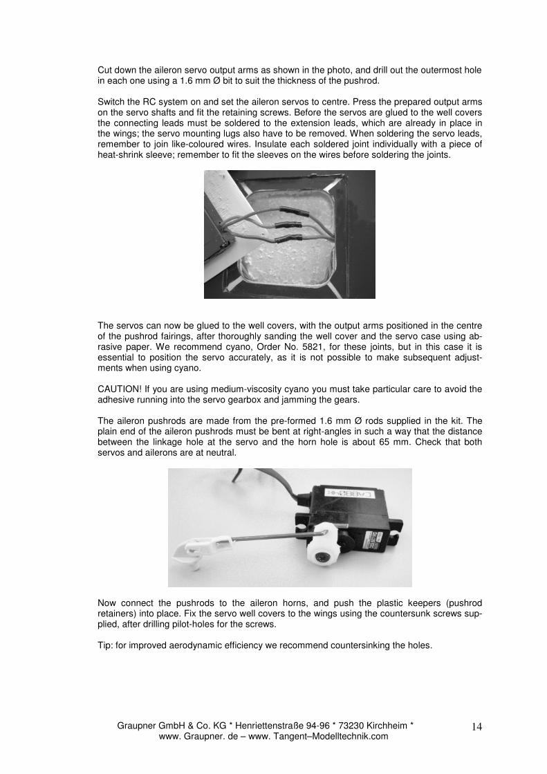
Cut down the aileron servo output arms as shown in the photo, and drill out the outermost hole in each one using a 1.6 mm Ø bit to suit the thickness of the pushrod. Switch the RC system on and set the aileron servos to centre. Press the prepared output arms on the servo shafts and fit the retaining screws. Before the servos are glued to the well covers the connecting leads must be soldered to the extension leads, which are already in place in the wings; the servo mounting lugs also have to be removed. When soldering the servo leads, remember to join like-coloured wires. Insulate each soldered joint individually with a piece of heat-shrink sleeve; remember to fit the sleeves on the wires before soldering the joints.
The servos can now be glued to the well covers, with the output arms positioned in the centre of the pushrod fairings, after thoroughly sanding the well cover and the servo case using ab-rasive paper. We recommend cyano, Order No. 5821, for these joints, but in this case it is essential to position the servo accurately, as it is not possible to make subsequent adjust-ments when using cyano. CAUTION! If you are using medium-viscosity cyano you must take particular care to avoid the adhesive running into the servo gearbox and jamming the gears.
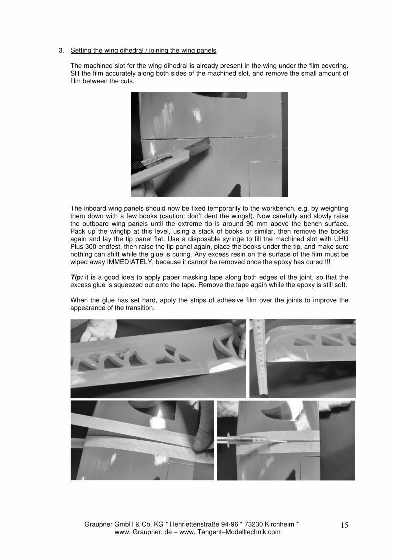
The aileron pushrods are made from the pre-formed 1.6 mm Ø rods supplied in the kit. The plain end of the aileron pushrods must be bent at right-angles in such a way that the distance between the linkage hole at the servo and the horn hole is about 65 mm. Check that both servos and ailerons are at neutral.
Now connect the pushrods to the aileron horns, and push the plastic keepers (pushrod retainers) into place. Fix the servo well covers to the wings using the countersunk screws sup-plied, after drilling pilot-holes for the screws. Tip: for improved aerodynamic efficiency we recommend countersinking the holes.
Graupner GmbH & Co. KG * Henriettenstraße 94-96 * 73230 Kirchheim * www. Graupner. de – www. Tangent–Modelltechnik.com
15
3. Setting the wing dihedral / joining the wing panels
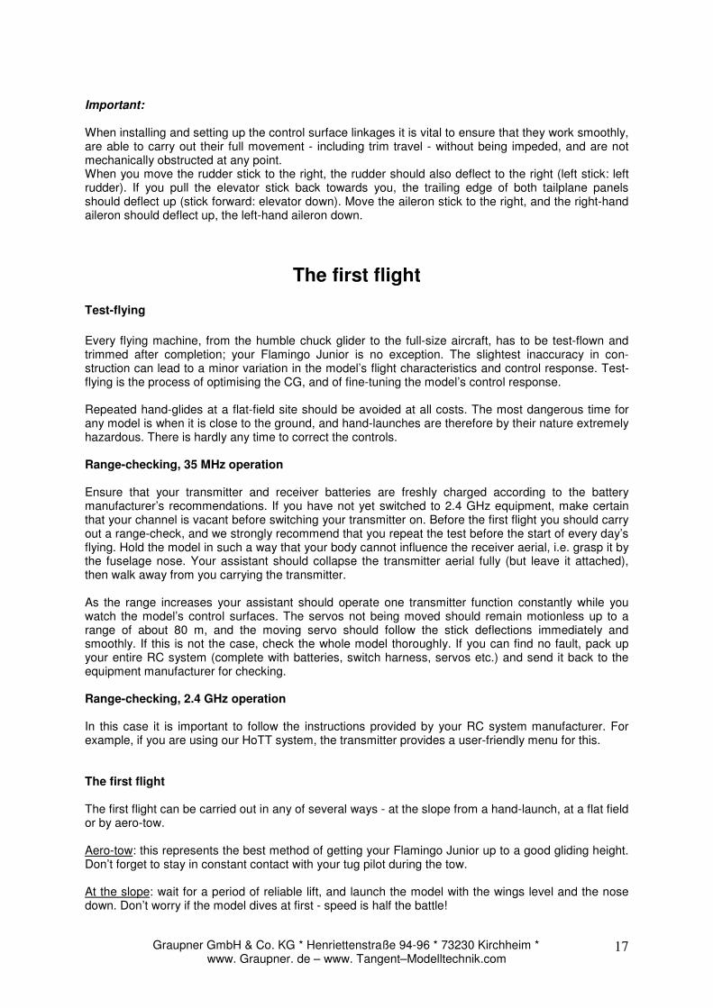
The machined slot for the wing dihedral is already present in the wing under the film covering. Slit the film accurately along both sides of the machined slot, and remove the small amount of film between the cuts.
The inboard wing panels should now be fixed temporarily to the workbench, e.g. by weighting them down with a few books (caution: don’t dent the wings!). Now carefully and slowly raise the outboard wing panels until the extreme tip is around 90 mm above the bench surface. Pack up the wingtip at this level, using a stack of books or similar, then remove the books again and lay the tip panel flat. Use a disposable syringe to fill the machined slot with UHU Plus 300 endfest, then raise the tip panel again, place the books under the tip, and make sure nothing can shift while the glue is curing. Any excess resin on the surface of the film must be wiped away IMMEDIATELY, because it cannot be removed once the epoxy has cured !!! Tip: it is a good idea to apply paper masking tape along both edges of the joint, so that the excess glue is squeezed out onto the tape. Remove the tape again while the epoxy is still soft. When the glue has set hard, apply the strips of adhesive film over the joints to improve the appearance of the transition.
Graupner GmbH & Co. KG * Henriettenstraße 94-96 * 73230 Kirchheim * www. Graupner. de – www. Tangent–Modelltechnik.com
16
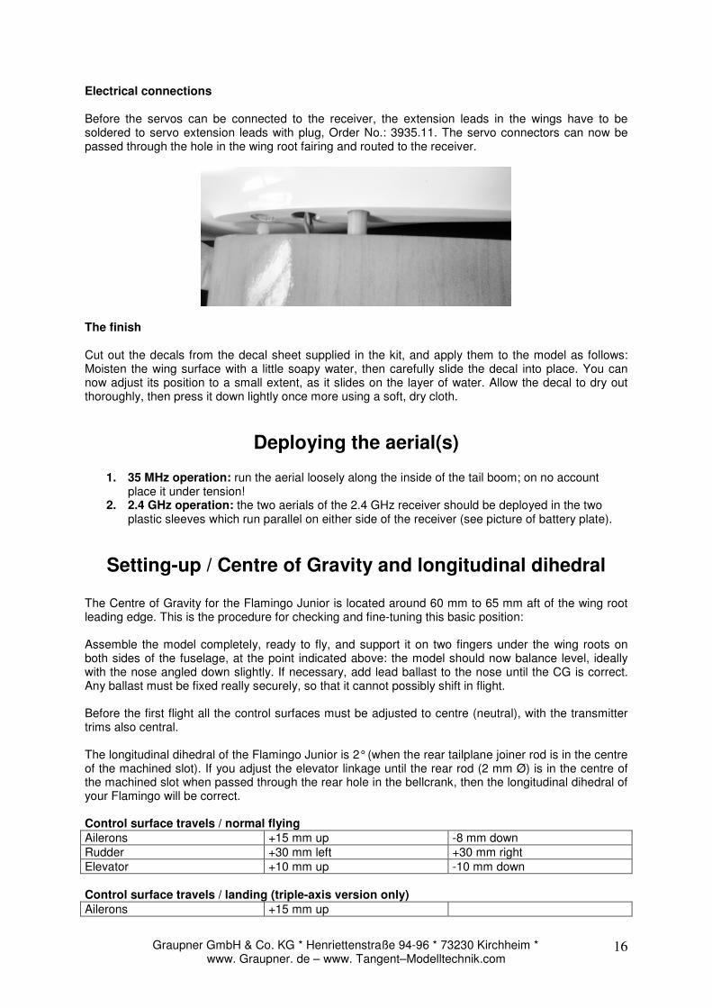
Electrical connections Before the servos can be connected to the receiver, the extension leads in the wings have to be soldered to servo extension leads with plug, Order No.: 3935.11. The servo connectors can now be passed through the hole in the wing root fairing and routed to the receiver.
The finish Cut out the decals from the decal sheet supplied in the kit, and apply them to the model as follows: Moisten the wing surface with a little soapy water, then carefully slide the decal into place. You can now adjust its position to a small extent, as it slides on the layer of water. Allow the decal to dry out thoroughly, then press it down lightly once more using a soft, dry cloth.
Deploying the aerial(s)
1. 35 MHz operation: run the aerial loosely along the inside of the tail boom; on no account place it under tension!
2. 2.4 GHz operation: the two aerials of the 2.4 GHz receiver should be deployed in the two plastic sleeves which run parallel on either side of the receiver (see picture of battery plate).
Setting-up / Centre of Gravity and longitudinal dihedral
The Centre of Gravity for the Flamingo Junior is located around 60 mm to 65 mm aft of the wing root leading edge. This is the procedure for checking and fine-tuning this basic position: Assemble the model completely, ready to fly, and support it on two fingers under the wing roots on both sides of the fuselage, at the point indicated above: the model should now balance level, ideally with the nose angled down slightly. If necessary, add lead ballast to the nose until the CG is correct. Any ballast must be fixed really securely, so that it cannot possibly shift in flight. Before the first flight all the control surfaces must be adjusted to centre (neutral), with the transmitter trims also central. The longitudinal dihedral of the Flamingo Junior is 2° (when the rear tailplane joiner rod is in the centre of the machined slot). If you adjust the elevator linkage until the rear rod (2 mm Ø) is in the centre of the machined slot when passed through the rear hole in the bellcrank, then the longitudinal dihedral of your Flamingo will be correct. Control surface travels / normal flying
Ailerons +15 mm up -8 mm down Rudder +30 mm left +30 mm right Elevator +10 mm up -10 mm down Control surface travels / landing (triple-axis version only)
Ailerons +15 mm up
Graupner GmbH & Co. KG * Henriettenstraße 94-96 * 73230 Kirchheim * www. Graupner. de – www. Tangent–Modelltechnik.com
17
Important: When installing and setting up the control surface linkages it is vital to ensure that they work smoothly, are able to carry out their full movement - including trim travel - without being impeded, and are not mechanically obstructed at any point. When you move the rudder stick to the right, the rudder should also deflect to the right (left stick: left rudder). If you pull the elevator stick back towards you, the trailing edge of both tailplane panels should deflect up (stick forward: elevator down). Move the aileron stick to the right, and the right-hand aileron should deflect up, the left-hand aileron down.
The first flight Test-flying
Every flying machine, from the humble chuck glider to the full-size aircraft, has to be test-flown and trimmed after completion; your Flamingo Junior is no exception. The slightest inaccuracy in con-struction can lead to a minor variation in the model’s flight characteristics and control response. Test-flying is the process of optimising the CG, and of fine-tuning the model’s control response. Repeated hand-glides at a flat-field site should be avoided at all costs. The most dangerous time for any model is when it is close to the ground, and hand-launches are therefore by their nature extremely hazardous. There is hardly any time to correct the controls. Range-checking, 35 MHz operation Ensure that your transmitter and receiver batteries are freshly charged according to the battery manufacturer’s recommendations. If you have not yet switched to 2.4 GHz equipment, make certain that your channel is vacant before switching your transmitter on. Before the first flight you should carry out a range-check, and we strongly recommend that you repeat the test before the start of every day’s flying. Hold the model in such a way that your body cannot influence the receiver aerial, i.e. grasp it by the fuselage nose. Your assistant should collapse the transmitter aerial fully (but leave it attached), then walk away from you carrying the transmitter. As the range increases your assistant should operate one transmitter function constantly while you watch the model’s control surfaces. The servos not being moved should remain motionless up to a range of about 80 m, and the moving servo should follow the stick deflections immediately and smoothly. If this is not the case, check the whole model thoroughly. If you can find no fault, pack up your entire RC system (complete with batteries, switch harness, servos etc.) and send it back to the equipment manufacturer for checking. Range-checking, 2.4 GHz operation In this case it is important to follow the instructions provided by your RC system manufacturer. For example, if you are using our HoTT system, the transmitter provides a user-friendly menu for this. The first flight The first flight can be carried out in any of several ways - at the slope from a hand-launch, at a flat field or by aero-tow. Aero-tow: this represents the best method of getting your Flamingo Junior up to a good gliding height. Don’t forget to stay in constant contact with your tug pilot during the tow. At the slope: wait for a period of reliable lift, and launch the model with the wings level and the nose down. Don’t worry if the model dives at first - speed is half the battle!
Graupner GmbH & Co. KG * Henriettenstraße 94-96 * 73230 Kirchheim * www. Graupner. de – www. Tangent–Modelltechnik.com
18
If necessary adjust the trims to achieve straight flight and a reasonable cruising speed. The next step is to fly turns alternately to left and right to check the model’s turning characteristics, the harmonisation (balance) between ailerons, elevator and rudder, and the aileron differential. If you still have plenty of height you should check the Centre of Gravity right at this early stage. The procedure for CG testing described here is a method of fine-tuning the model’s balance. It can only work when air movements are slight, and when the initial CG position is exactly correct. It is bound to fail if the model is a long way out of balance and / or there is a strong wind. In breezy conditions it is difficult to set up the model for normal cruise speed, as it is hard to judge its speed relative to the surrounding air. Trim the model carefully for normal cruising speed, which should be comfortably above stalling speed. The model should show no tendency to “hunt” up and down, or mush along close to the stall. Now - assuming that you have plenty of height in hand - apply full down-elevator briefly to place the model in a vertical dive. Immediately centre the stick and watch the aeroplane carefully. The CG is correct if it recovers to normal flight in a broad, gentle curving arc (100 m) by itself. The CG is too far forward if the model bounces up again immediately and climbs strongly. Remedy: remove lead ballast from the fuselage nose; apply slight down-elevator trim. The CG is too far aft if the model shows no tendency to recover by itself - the dive may even become steeper. Remedy: immediately recover the model with gentle up-elevator. Add a little lead ballast to the fuse-lage nose, fix it securely, and apply a little up-trim. Flat-field flying Flat-field flying is relatively non-hazardous since there is no risk of the model “landing out” at the foot of the hill, as with slope soaring. Nevertheless, making the best use of flat field thermals is not particularly easy, and calls for considerable skill and experience. Areas of rising air are harder to detect and recognise at a flat field, because they tend to occur at higher altitude than at the hillside, where it is often possible to find lift while the model is cruising along the edge of the slope and then circle away in it. A thermal at a flat field which occurs directly overhead is very hard to recognise, and exploiting it to the full requires a highly skilled pilot. For this reason it is always best to go thermal seeking off to one side of where you are standing. You will recognise thermal contact by the model’s behaviour. Good thermals are obvious because the model will climb strongly, but it takes a practised eye to detect weak thermals, and you will need a lot of skill to make use of them. With a little practice you will be able to recognise likely trigger points for thermals in the local landscape. The ground warms up in the sun’s heat, but heat absorption varies according to the type of terrain and the angle of the sun’s rays. The air over the warmer ground becomes warmer in turn, and the mass of warm air flows along close to the ground, driven by any breeze. Any obstruction - a shrub or tree, a fence, the edge of a wood, a hill, a passing car, even your own model on the landing approach - may cause this warm air to leave the ground and rise. Imagine a drop of water on the ceiling, wandering around aim-lessly, and initially remaining stuck to the ceiling. If it strikes an obstruction it will fall on your head. A triggered thermal can be imagined as the opposite of the drop of water. The most obvious thermal triggers include sharply defined snow fields on mountain slopes. The air above the snow field is cooled, and flows downhill; at the edge of the snow field, part-way down the valley, the cool air meets warm air flowing gently uphill, and pushes it up and away as if cut off by a knife. The result is an extremely powerful but bumpy thermal bubble. The pilot’s task is to locate the rising warm air and centre your model in it. You will need to control the glider constantly to keep it centred, as you can expect the most rapid climb rate in the core of the thermal. Once again, this technique does demand some skill. To avoid losing sight of the model be sure to leave the thermal in good time. Bear in mind that the aircraft is always easier to see under a cloud than against a clear blue sky. If you have to lose height in a hurry, do bear the following in mind: the Flamingo Junior is a robust beginner’s model, but not a high-performance aircraft. The airframe strength is finite, i.e. a steep dive followed by an abrupt pull-out may result in the loss of the model.
Graupner GmbH & Co. KG * Henriettenstraße 94-96 * 73230 Kirchheim * www. Graupner. de – www. Tangent–Modelltechnik.com
19
Flying at the slope
Ridge soaring is an extremely attractive form of model flying. Flying for hours on end in slope lift, without needing any outside aid for launching, must be one of the finest of modelling experiences. But to “milk” a thermal to the limits of vision, bring it down again in a continuous series of aerobatic manoeuvres, and then to repeat the whole show - that must surely be the last word in model flying. But take care - there are dangers for your model lurking at the slope. Firstly, in most cases landing is much more difficult than at a flat field site. It is usually necessary to land in the lee of the hill where the air is turbulent; this calls for concentration and a high-speed approach with last-minute airbrake extension. A landing on the slope face, i.e. right in the slope lift, is even more difficult. Here the trick is to approach slightly downwind, up the slope, and flare at the right moment, just before touch-down. A further danger is failure of the slope lift or thermal when the model is in a difficult position, resulting in a risky landing in the valley, but there are ways of reducing that risk. Study the valley floor before you launch, and seek out a possible landing site there. Walk down and study the site so that you know where any landing approach obstructions are, and whether the “local” wind is as you would expect it. If an out-landing is unavoidable it is best to land just as at a flat field site with a standard approach and a short, straight final leg with brakes deployed. Keep the model in your line of sight at all times over the planned landing site, as this avoids the danger of an uncontrolled landing. Follow these hints and you will safely reach the site. If the sun is shining you will be able to judge the model’s height by the distance between the model and its own shadow, and this will allow you to land with considerable accuracy “way down there”. Never give up; thermals can be found very low down. However, once you have initiated the landing approach do continue and make a landing, as you are unlikely to find real lift that low. With luck you will manage a soft landing. Now take your time to note the landing position and the best route to it. Look around for landmarks in the countryside which will help you locate the model when searching. However, the main point to remember when scratching for a thermal below launch height is - “don't panic”: remember that in almost every case it is the pilot that is the problem, rather than the model. If you have a flying colleague who tries to help by giving a continuous commentary and giving what he thinks is useful advice all the time, tell him to shut up. A colleague who wishes to help you will restrict himself to very short and really helpful comments, e.g. by pointing out other models whose pilots have found a thermal, a circling bird of prey or a safe approach to the planned landing site. A really good friend will even launch his own model, fly down into the valley and help you find a thermal. With two models the chances of success are much higher. Safety
Safety is the First Commandment when flying any model aircraft. Third party insurance should be considered a basic essential. If you join a model club suitable cover will usually be available through the organisation. It is your personal responsibility to ensure that your insurance is adequate. Make it your job to keep your models and your radio control system in perfect order at all times. Check the correct charging procedure for the NC batteries used in your RC set. Make use of all sensible safety systems and precautions which are advised for your system. Gather as much information as you can from various product catalogues, and from your local model shop proprietor. Always fly with a responsible attitude. You may think that flying low over other people’s heads is proof of your piloting skill, but others know better: the real expert does not need to prove himself in such childish ways. Let other pilots know that this is what you think too. Always fly in such a way that you avoid endangering yourself or others. Bear in mind that even the best RC system in the world is subject to outside interference. No matter how many years of accident-free flying you have under your belt, you have no idea what will happen in the next minute. The fascination of it all
Take your time to get to know your new Flamingo Junior really well. You will soon learn to appreciate the model’s docile handling, and its ability to open up the world of Contestline models to you. You can join us in savouring one of the few types of sport which combine high technology, manual dexterity, and sophisticated personal skills. You can fly alone or with friends, and at the same time you can enjoy the pleasures of nature - treats which have become rare in today's world.
Graupner GmbH & Co. KG * Henriettenstraße 94-96 * 73230 Kirchheim * www. Graupner. de – www. Tangent–Modelltechnik.com
20
Recommended RC equipment Rudder and elevator DES 586 BB Order No.: 7931 Ailerons DES 586 BB Order No: 7931 RC system Four-channel system Recommended power system Propeller Cam Folding Prop, 23 x 12 Order No.: 1335.23.12 Motor Inline 475 14.8 V Order No.: 6607 Speed controller Compact Fly 25 BEC Order No.: 7221 LiPo flight pack 3/2500 20C Order No.: 7633.3 We - the GRAUPNER / TANGENT Modellsport team - wish you as many hours of pleasure in building and flying your new model as we have had.
GRAUPNER / TANGENT – Modellsport
Dieter Bär – Model Development
Graupner GmbH & Co. KG * Henriettenstraße 94-96 * 73230 Kirchheim * www. Graupner. de – www. Tangent–Modelltechnik.com
21
Appendix Parts List Kit contents
Quantity Description Note
1 Canopy Vac. moulded 1 Pair of wing panels Ready made, ARF 1 Pair of tailplane panels Ready made, ARF 1 Rudder Ready made, ARF 1 Contest fittings bag Parts List 1 Wing joiner Ready made / GRP 1 Laser-cut wooden parts set Parts List 1 GRP fuselage Ready made 1 Building instructions Monochrome printed 1 Decal sheet Screen-printed 1 Servolock set ABS / Parts List Contest small parts bag
Qu. Description Application Material Dimensions
2 Aerial sleeve 2.4 GHz aerial guide ABS tube 3/2 x approx. 70 mm 1 Velcro tape Receiver mounting Hook / loop tape approx. 25 x 70 mm 2 Multilock wing retainer Wing retention Plastic Ready made 2 Incidence peg Wing joiner part Spring steel 3 Ø x 40 mm 4 Pushrod keeper Horn retainer Plastic Ready made 2 Point-hinge Rudder hinge Plastic Ready made 3 Horn Aileron / rudder linkages Plastic Ready made 2 Tailplane joiner rod Tailplane joiner Spring steel 2 Ø x 80 mm 2 Control surface pushrod Aileron linkage Spring steel 1.6 Ø x 100 mm 1 Wing joiner Wing joiner GRP rod 8 Ø x 235 mm 1 Canopy retaining spring Canopy retainer ABS strip Ready made 1 Tow-hook Glider launch aid Steel Ready made
Laser-cut wooden parts
Qu. Description Application Material Dimensions
1 Servo plate RC installation Plywood Ready made 1 ** Battery plate Battery mounting Plywood Ready made 1 ** Motor bulkhead (installed) Motor mounting Plywood Ready made 2 Film panel, short Dihedral joint cover Covering film Oversize 1 Tow-hook support block Tow-hook support Hardwood Ready made 2 Film panel, long Aileron gap cover Covering film Oversize ** electric version only Servolock set
Qu. Description Application Material Dimensions
1 L.H. servo fairing Servo well cover ABS Ready made 1 R.H. servo fairing Servo well cover ABS Ready made 8 Countersunk screw Well cover attachment Steel 2 Ø x 10mm Modifications in form and composition reserved.
Graupner GmbH & Co. KG * Henriettenstraße 94-96 * 73230 Kirchheim * www. Graupner. de – www. Tangent–Modelltechnik.com
22