Embed Size (px)
Citation preview
MODE
FAN 74Off
Auto
F
Model GC-TBZ48Battery Powered Z-Wave
ThermostatInstallation & Operation Guide
Table of ContentsTypical Wiring for Standard Gas/Electric HVAC System . . . . . . . . . . . . . . . . . . . . . . . . . . . . . . . . . . . . . .2Typical Wiring for Heat Pump HVAC System . . . . . . . . . . . . . . . . . . . . . . . . . . . . . . . . . . . . . . . . . . . . . . .3Thermostat Power . . . . . . . . . . . . . . . . . . . . . . . . . . . . . . . . . . . . . . . . . . . . . . . . . . . . . . . . . . . . . . . . . . . .4
The C Wire . . . . . . . . . . . . . . . . . . . . . . . . . . . . . . . . . . . . . . . . . . . . . . . . . . . . . . . . . . . . . . . . . . . . . .424VAC Power . . . . . . . . . . . . . . . . . . . . . . . . . . . . . . . . . . . . . . . . . . . . . . . . . . . . . . . . . . . . . . . . . . .4Ba ery Power . . . . . . . . . . . . . . . . . . . . . . . . . . . . . . . . . . . . . . . . . . . . . . . . . . . . . . . . . . . . . . . . . . .4Z-Wave Opera on when Ba ery Powered . . . . . . . . . . . . . . . . . . . . . . . . . . . . . . . . . . . . . . . . . . . .4
Remove Exis ng Thermostat . . . . . . . . . . . . . . . . . . . . . . . . . . . . . . . . . . . . . . . . . . . . . . . . . . . . . . . . . . .5Wiring Colors . . . . . . . . . . . . . . . . . . . . . . . . . . . . . . . . . . . . . . . . . . . . . . . . . . . . . . . . . . . . . . . . . . .5
Install the Back Panel . . . . . . . . . . . . . . . . . . . . . . . . . . . . . . . . . . . . . . . . . . . . . . . . . . . . . . . . . . . . . . . . . .6Standard HVAC System Connec ons . . . . . . . . . . . . . . . . . . . . . . . . . . . . . . . . . . . . . . . . . . . . . . . . . . . . .7
Single and Dual Transformer Systems (Split Systems) . . . . . . . . . . . . . . . . . . . . . . . . . . . . . . . . . . .7Single Transformer System . . . . . . . . . . . . . . . . . . . . . . . . . . . . . . . . . . . . . . . . . . . . . . . . . . . .7Dual Transformer Systems . . . . . . . . . . . . . . . . . . . . . . . . . . . . . . . . . . . . . . . . . . . . . . . . . . . .8
Heat Pump HVAC System Connec ons . . . . . . . . . . . . . . . . . . . . . . . . . . . . . . . . . . . . . . . . . . . . . . . . . . .9Mount the Thermostat . . . . . . . . . . . . . . . . . . . . . . . . . . . . . . . . . . . . . . . . . . . . . . . . . . . . . . . . . . . . . . .10Ba ery Installa on. . . . . . . . . . . . . . . . . . . . . . . . . . . . . . . . . . . . . . . . . . . . . . . . . . . . . . . . . . . . . . . . . . .10Thermostat Setup Menus . . . . . . . . . . . . . . . . . . . . . . . . . . . . . . . . . . . . . . . . . . . . . . . . . . . . . . . . . . . . .11
Preset HVAC System se ngs . . . . . . . . . . . . . . . . . . . . . . . . . . . . . . . . . . . . . . . . . . . . . . . . . . . . . .11Wait Mode . . . . . . . . . . . . . . . . . . . . . . . . . . . . . . . . . . . . . . . . . . . . . . . . . . . . . . . . . . . . . . . . . . . .11Minimum Run Time (MRT) . . . . . . . . . . . . . . . . . . . . . . . . . . . . . . . . . . . . . . . . . . . . . . . . . . . . . . .11Entering Menu Mode . . . . . . . . . . . . . . . . . . . . . . . . . . . . . . . . . . . . . . . . . . . . . . . . . . . . . . . . . . .12
Menu Mode Naviga on . . . . . . . . . . . . . . . . . . . . . . . . . . . . . . . . . . . . . . . . . . . . . . . . . . . . .12System Menu . . . . . . . . . . . . . . . . . . . . . . . . . . . . . . . . . . . . . . . . . . . . . . . . . . . . . . . . . . . . . . . . . .13
System Type . . . . . . . . . . . . . . . . . . . . . . . . . . . . . . . . . . . . . . . . . . . . . . . . . . . . . . . . . . . . . . .13Fan Type (For Standard HVAC systems only) . . . . . . . . . . . . . . . . . . . . . . . . . . . . . . . . . . . .13Changeover Type (For Heat Pump HVAC Systems Only) . . . . . . . . . . . . . . . . . . . . . . . . . . .13
Z-Wave Installa on . . . . . . . . . . . . . . . . . . . . . . . . . . . . . . . . . . . . . . . . . . . . . . . . . . . . . . . . . . . . . .14Inclusion and Exclusion . . . . . . . . . . . . . . . . . . . . . . . . . . . . . . . . . . . . . . . . . . . . . . . . . . . . . . . . . .14Clock Menu . . . . . . . . . . . . . . . . . . . . . . . . . . . . . . . . . . . . . . . . . . . . . . . . . . . . . . . . . . . . . . . . . . . .15
Se ng the Clock . . . . . . . . . . . . . . . . . . . . . . . . . . . . . . . . . . . . . . . . . . . . . . . . . . . . . . . . . . .15INFO Menu . . . . . . . . . . . . . . . . . . . . . . . . . . . . . . . . . . . . . . . . . . . . . . . . . . . . . . . . . . . . . . . . . . . .15Advanced System Se ngs Menu . . . . . . . . . . . . . . . . . . . . . . . . . . . . . . . . . . . . . . . . . . . . . . . . . .16
Thermostat Opera on . . . . . . . . . . . . . . . . . . . . . . . . . . . . . . . . . . . . . . . . . . . . . . . . . . . . . . . . . . . . . . . .18Main Thermostat Screen . . . . . . . . . . . . . . . . . . . . . . . . . . . . . . . . . . . . . . . . . . . . . . . . . . . . . . . . .18Backlight and Bu on Opera on . . . . . . . . . . . . . . . . . . . . . . . . . . . . . . . . . . . . . . . . . . . . . . . . . . .18Display . . . . . . . . . . . . . . . . . . . . . . . . . . . . . . . . . . . . . . . . . . . . . . . . . . . . . . . . . . . . . . . . . . . . . . . .18Staging Indicators . . . . . . . . . . . . . . . . . . . . . . . . . . . . . . . . . . . . . . . . . . . . . . . . . . . . . . . . . . . . . . .18Se ng the System Mode . . . . . . . . . . . . . . . . . . . . . . . . . . . . . . . . . . . . . . . . . . . . . . . . . . . . . . . . .19
System Modes . . . . . . . . . . . . . . . . . . . . . . . . . . . . . . . . . . . . . . . . . . . . . . . . . . . . . . . . . . . . .19Special Heat Pump Mode: Emergency Heat . . . . . . . . . . . . . . . . . . . . . . . . . . . . . . . . . . . . .19
Se ng the Hea ng or Cooling Temperature Setpoint. . . . . . . . . . . . . . . . . . . . . . . . . . . . . . . . . .20Automa c Setpoint Push . . . . . . . . . . . . . . . . . . . . . . . . . . . . . . . . . . . . . . . . . . . . . . . . . . . .20
Se ng the Fan Mode . . . . . . . . . . . . . . . . . . . . . . . . . . . . . . . . . . . . . . . . . . . . . . . . . . . . . . . . . . . .21Fan Modes . . . . . . . . . . . . . . . . . . . . . . . . . . . . . . . . . . . . . . . . . . . . . . . . . . . . . . . . . . . . . . . .21
User Customiza on . . . . . . . . . . . . . . . . . . . . . . . . . . . . . . . . . . . . . . . . . . . . . . . . . . . . . . . . . . . . .22User preference se ngs. . . . . . . . . . . . . . . . . . . . . . . . . . . . . . . . . . . . . . . . . . . . . . . . . . . . .22
Clock Menu . . . . . . . . . . . . . . . . . . . . . . . . . . . . . . . . . . . . . . . . . . . . . . . . . . . . . . . . . . . . . . . . . . . .23Se ng the Clock . . . . . . . . . . . . . . . . . . . . . . . . . . . . . . . . . . . . . . . . . . . . . . . . . . . . . . . . . . .23
INFO Menu . . . . . . . . . . . . . . . . . . . . . . . . . . . . . . . . . . . . . . . . . . . . . . . . . . . . . . . . . . . . . . . . . . . .23Specifi ca ons . . . . . . . . . . . . . . . . . . . . . . . . . . . . . . . . . . . . . . . . . . . . . . . . . . . . . . . . . . . . . . . . . . . . . . .24Regulatory Informa on . . . . . . . . . . . . . . . . . . . . . . . . . . . . . . . . . . . . . . . . . . . . . . . . . . . . . . . . . . . . . . .25Industry Canada No ces . . . . . . . . . . . . . . . . . . . . . . . . . . . . . . . . . . . . . . . . . . . . . . . . . . . . . . . . . . . . . .25Limited Warranty . . . . . . . . . . . . . . . . . . . . . . . . . . . . . . . . . . . . . . . . . . . . . . . . . . . . . . . . . . . . . . . . . . . .25
Copyright © 2015 Nortek Security & Control LLC 1
GC-TBZ48
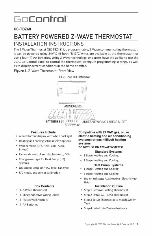
BATTERY POWERED Z-WAVE THERMOSTATINSTALLATION INSTRUCTIONSThe Z-Wave Thermostat (GC-TBZ48) is a programmable, Z-Wave communica ng thermostat. It can be powered using 24VAC (if both “R”&”C”wires are available at the thermostat), or using four (4) AA ba eries. Using Z-Wave technology, end users have the ability to use the 2GIG Go!Control panel to control the thermostat, confi gure programming se ngs, as well as to display current condi ons in the home or offi ce.Figure 1. Z-Wave Thermostat Front View
MODE
FAN
Y
BATTERIES (4) PHILLIPS SCREWS (2)
ANCHORS (2)
ADHESIVE WIRING LABELS SHEET
GC-TBZ48 THERMOSTAT
Features Include:• A fi xed format display with white backlight• Hea ng and cooling setup display op ons• System mode (OFF, Heat, Cool, Auto,
E-Heat)• Fan mode control and display (Auto, ON)• Changeover type for Heat Pump (HP)
systems• On-screen setup of HVAC type, Fan type• F/C mode, and sensor calibra on
Compatible with 24 VAC gas, oil, or electric heating and air conditioning systems; or gas millivolt heating systemsDO NOT USE ON 120VAC SYSTEMS!
Standard Systems• 1 Stage Hea ng and Cooling• 2 Stage Hea ng and Cooling
Heat Pump Systems• 1 Stage Hea ng and Cooling• 2 Stage Hea ng and Cooling• 2nd or 3rd Stage Aux Hea ng (Electric Heat
StripsBox Contents
• 1─Z-Wave Thermostat• 1─Sheet Adhesive Wiring Labels• 2─Plas c Wall Anchors• 4─AA Ba eries
Installation Outline• Step 1 Remove Exis ng Thermostat• Step 2 Install GC-TBZ48 Thermostat• Step 3 Setup Thermostat to match System
Type• Step 4 Install into Z-Wave Network
2 Copyright © 2015 Nortek Security & Control
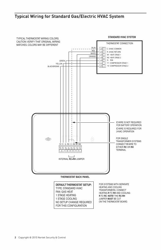
Typical Wiring for Standard Gas/Electric HVAC System
THERMOSTAT CONNECTION
C 24VAC COMMON
R 24VAC RETURN
W1 HEAT STAGE 1
W2 HEAT STAGE 2G FAN
Y1 COMPRESSOR STAGE 1
Y2 COMPRESSOR STAGE 2
TYPICAL THERMOSTAT WIRING COLORS.CAUTION: VERIFY THAT ORIGINAL WIRINGMATCHES. COLORS MAY BE DIFFERENT
STANDARD HVAC SYSTEM
BLUE
REDWHITE
ORANGE
GREEN
YELLOWBLACK/BROWN
THERMOSTAT BACK PANEL
INTERNAL RC=RH JUMPER
C WIRE IS NOT REQUIREDFOR BATTERY OPERATIONC WIRE IS REQUIRED FOR24VAC OPERATION
DEFAULT THERMOSTAT SETUP:TYPE: STANDARD HVACFAN: GAS HEAT1 STAGE HEATING1 STAGE COOLINGNO SETUP CHANGE REQUIREDFOR THIS CONFIGURATION
Y2 Y1 G RC C RH W1 W2
FOR SINGLE TRANSFORMER SYSTEMS CONNECT R WIRE TO EITHER RC OR RH TERMINAL
FOR SYSTEMS WITH SEPARATE HEATING AND COOLING TRANSFORMERS, CONNECTHEATING R TO RH AND COOLINGR TO RC. NOTE! THE RC-RH JUMPER MUST BE CUTON THE THERMOSTAT BOARD.
Copyright © 2015 Nortek Security & Control LLC 3
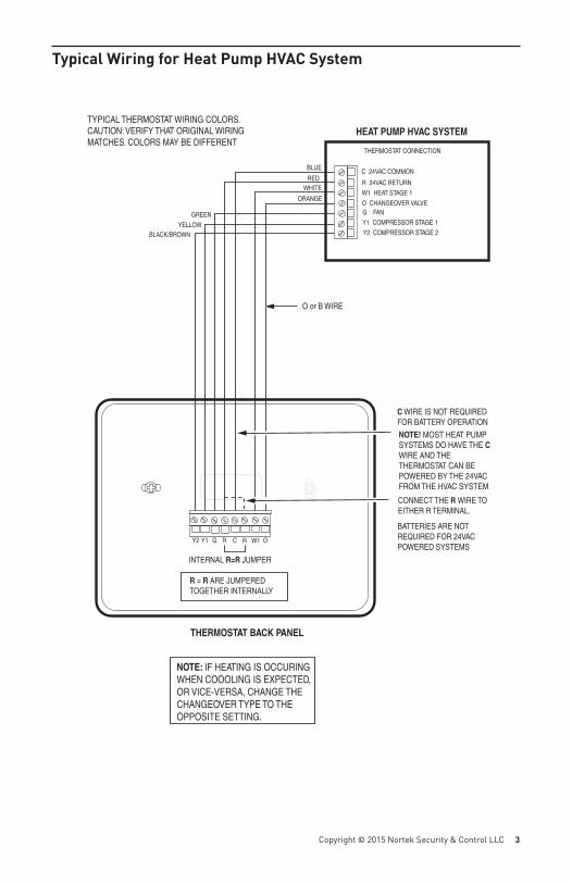
Typical Wiring for Heat Pump HVAC System
THERMOSTAT CONNECTION
C 24VAC COMMON
R 24VAC RETURN
W1 HEAT STAGE 1
O CHANGEOVER VALVEG FAN
Y1 COMPRESSOR STAGE 1
Y2 COMPRESSOR STAGE 2
TYPICAL THERMOSTAT WIRING COLORS.CAUTION: VERIFY THAT ORIGINAL WIRINGMATCHES. COLORS MAY BE DIFFERENT
HEAT PUMP HVAC SYSTEM
BLUE
REDWHITE
ORANGE
GREEN
YELLOWBLACK/BROWN
THERMOSTAT BACK PANEL
Y2 Y1 G R C R W1 O
INTERNAL R=R JUMPER
C WIRE IS NOT REQUIREDFOR BATTERY OPERATION
BATTERIES ARE NOT REQUIRED FOR 24VAC POWERED SYSTEMS
CONNECT THE R WIRE TO EITHER R TERMINAL.
R = R ARE JUMPERED TOGETHER INTERNALLY
NOTE: IF HEATING IS OCCURINGWHEN COOOLING IS EXPECTED,OR VICE-VERSA, CHANGE THECHANGEOVER TYPE TO THEOPPOSITE SETTING.
O or B WIRE
NOTE! MOST HEAT PUMPSYSTEMS DO HAVE THE C WIRE AND THE THERMOSTAT CAN BEPOWERED BY THE 24VAC FROM THE HVAC SYSTEM
4 Copyright © 2015 Nortek Security & Control
Thermostat PowerThe thermostat can be powered by either 24VAC from the HVAC system or from four (4) type AA internal ba eries. DO NOT use this thermostat for line voltage controls (120/240VAC).
The C WireIf the 24VAC common wire (usually blue) is present and is connected to 24VAC common at the HVAC system end, the thermostat can be powered from the HVAC system and ba eries are not required. If there is no common wire, ba eries are required.
24VAC PowerPowering the thermostat with 24VAC power requires both the 24VAC “C” common wire (typically a blue wire) and the 24VAC ”R” return wire (typically a red wire).
Ba ery PowerPowering the thermostat from ba eries does not require a “C” wire connec on.DO NOT install ba eries if the thermostat is powered by 24VAC. They are not required for backup. If the thermostat is powered by ba eries, the thermostat will operate for approximately (2) two years on four (4) AA Alkaline ba eries depending on the frequency of user opera ons and backlight opera on. Always use Alkaline ba eries and replace in complete sets of four (4) at a me.
Z-Wave Opera on when Ba ery PoweredIMPORTANT: If the thermostat is installed on a Z-Wave network, while it is ba ery powered, it will NOT work as a Z-Wave repeater.CAUTION: Do not install ba eries and temporarily power the thermostat from 24VAC to include onto a Z-Wave network. Shortened ba ery life may occur when 24VAC power is removed.
Copyright © 2015 Nortek Security & Control LLC 5
Remove Existing Thermostat• Turn off the power to the thermostat. This is usually done at the hea ng/cooling system or
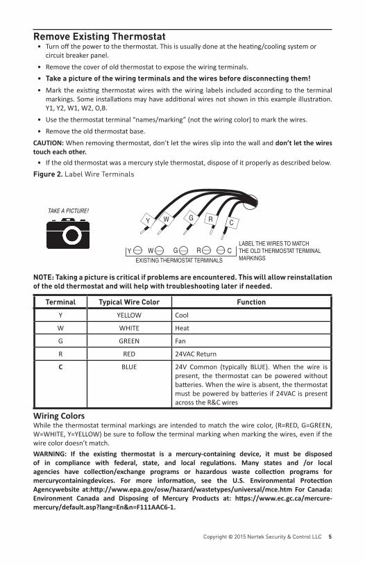
circuit breaker panel.• Remove the cover of old thermostat to expose the wiring terminals.• Take a picture of the wiring terminals and the wires before disconnecting them!• Mark the exis ng thermostat wires with the wiring labels included according to the terminal
markings. Some installa ons may have addi onal wires not shown in this example illustra on. Y1, Y2, W1, W2, O,B.
• Use the thermostat terminal “names/marking” (not the wiring color) to mark the wires.• Remove the old thermostat base.
CAUTION: When removing thermostat, don’t let the wires slip into the wall and don’t let the wires touch each other.
• If the old thermostat was a mercury style thermostat, dispose of it properly as described below.Figure 2. Label Wire Terminals
NOTE: Taking a picture is critical if problems are encountered. This will allow reinstallation of the old thermostat and will help with troubleshooting later if needed.
Terminal Typical Wire Color Function
Y YELLOW Cool
W WHITE Heat
G GREEN Fan
R RED 24VAC Return
C BLUE 24V Common (typically BLUE). When the wire is present, the thermostat can be powered without ba eries. When the wire is absent, the thermostat must be powered by ba eries if 24VAC is present across the R&C wires
Wiring ColorsWhile the thermostat terminal markings are intended to match the wire color, (R=RED, G=GREEN, W=WHITE, Y=YELLOW) be sure to follow the terminal marking when marking the wires, even if the wire color doesn’t match. WARNING: If the exis ng thermostat is a mercury-containing device, it must be disposed of in compliance with federal, state, and local regula ons. Many states and /or local agencies have collec on/exchange programs or hazardous waste collec on programs for mercurycontainingdevices. For more informa on, see the U.S. Environmental Protec on Agencywebsite at:h p://www.epa.gov/osw/hazard/wastetypes/universal/mce.htm For Canada: Environment Canada and Disposing of Mercury Products at: h ps://www.ec.gc.ca/mercure-mercury/default.asp?lang=En&n=F111AAC6-1.
CRGWY
CRGWYLABEL THE WIRES TO MATCHTHE OLD THERMOSTAT TERMINALMARKINGSEXISTING THERMOSTAT TERMINALS
TAKE A PICTURE!
6 Copyright © 2015 Nortek Security & Control
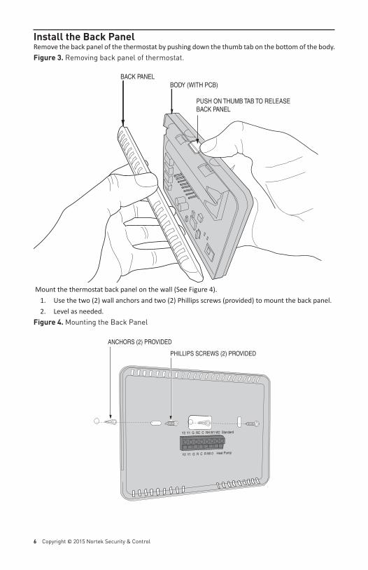
Install the Back PanelRemove the back panel of the thermostat by pushing down the thumb tab on the bo om of the body.Figure 3. Removing back panel of thermostat.
Mount the thermostat back panel on the wall (See Figure 4). 1. Use the two (2) wall anchors and two (2) Phillips screws (provided) to mount the back panel. 2. Level as needed.
Figure 4. Mounting the Back Panel
BACK PANELBODY (WITH PCB)
PUSH ON THUMB TAB TO RELEASEBACK PANEL
Y2 Y1 G RC C RH W1 W2 Standard
Y2 Y1 G R C R WI 0 Heat Pump
ANCHORS (2) PROVIDED
PHILLIPS SCREWS (2) PROVIDED
Copyright © 2015 Nortek Security & Control LLC 7
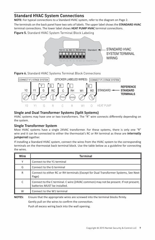
Standard HVAC System ConnectionsNOTE: For typical connec ons to a Standard HVAC system, refer to the diagram on Page 2.The terminals on the back panel have two sets of labels. The upper label shows the STANDARD HVAC terminal connec ons. The lower label shows HEAT PUMP HVAC terminal connec ons.Figure 5. Standard HVAC System Terminal Block Labeling
Figure 6. Standard HVAC Systems Terminal Block Connections
Single and Dual Transformer Systems (Split Systems)HVAC systems may have one or two transformers. The “R” wire connects diff erently depending on the system.
Single Transformer SystemMost HVAC systems have a single 24VAC transformer. For these systems, there is only one “R” wire and it can be connected to either the thermostat’s RC or RH terminal as these are internally jumpered together.If installing a Standard HVAC system, connect the wires from the HVAC system to the corresponding terminals on the thermostat back terminal block. Use the table below as a guideline for connec ng the wires.
Wire Terminal
Y Connect to the Y1 terminal
G Connect to the G terminal
R Connect to either RC or RH terminals (Except for Dual Transformer Systems, See Next Page)
C Connect to the C terminal. C wire (24VAC common) may not be present. If not present, ba eries MUST be installed.
W Connect to the W1 terminal
NOTES: Ensure that the appropriate wires are screwed into the terminal blocks fi rmly. Gently pull on the wires to confi rm the connec on. Push all excess wiring back into the wall opening.
Y2 Y1 G RC C RH W1 W2
WCRGY
STANDARD
Y2 Y1 G R C R W1 O HEAT PUMP
(STICKER LABELED WIRES)
REFERENCESTANDARDTERMINALS
CONNECT IF 2 STAGE SYSTEM CONNECT IF 2 STAGE SYSTEM
Y2 Y1 G RC C RH W1W2 Standard
Y2 Y1 G R C R W1 O Heat Pump
STANDARD HVAC SYSTEM TERMINAL WIRING
8 Copyright © 2015 Nortek Security & Control
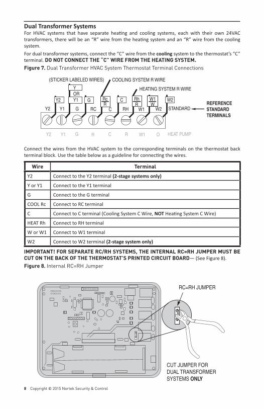
Dual Transformer SystemsFor HVAC systems that have separate hea ng and cooling systems, each with their own 24VAC transformers, there will be an “R” wire from the hea ng system and an “R” wire from the cooling system. For dual transformer systems, connect the “C” wire from the cooling system to the thermostat’s “C” terminal. DO NOT CONNECT THE “C” WIRE FROM THE HEATING SYSTEM.Figure 7. Dual Transformer HVAC System Thermostat Terminal Connections
Connect the wires from the HVAC system to the corresponding terminals on the thermostat back terminal block. Use the table below as a guideline for connec ng the wires.
Wire TerminalY2 Connect to the Y2 terminal (2-stage systems only)
Y or Y1 Connect to the Y1 terminal
G Connect to the G terminal
COOL Rc Connect to RC terminal
C Connect to C terminal (Cooling System C Wire, NOT Hea ng System C Wire)
HEAT Rh Connect to RH terminal
W or W1 Connect to W1 terminal
W2 Connect to W2 terminal (2-stage system only)
IMPORTANT! FOR SEPARATE RC/RH SYSTEMS, THE INTERNAL RC=RH JUMPER MUST BE CUT ON THE BACK OF THE THERMOSTAT’S PRINTED CIRCUIT BOARD— (See Figure 8).Figure 8. Internal RC=RH Jumper
RC=RH JUMPER
CUT JUMPER FORDUAL TRANSFORMERSYSTEMS ONLY
Y2 Y1 G RC C RH W1 W2W
CG
STANDARD
Y2 Y1 G R C R W1 O HEAT PUMP
(STICKER LABELED WIRES)
REFERENCESTANDARDTERMINALS
Rc Rh
HEATING SYSTEM R WIRE
COOLING SYSTEM R WIRE
Y2 W2
Y OR Y1
R RW1
Copyright © 2015 Nortek Security & Control LLC 9
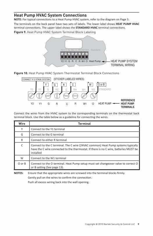
Heat Pump HVAC System Connections NOTE: For typical connec ons to a Heat Pump HVAC system, refer to the diagram on Page 3.The terminals on the back panel have two sets of labels. The lower label shows HEAT PUMP HVAC terminal connec ons. The upper label shows the STANDARD HVAC terminal connec ons.Figure 9. Heat Pump HVAC System Terminal Block Labeling
Figure 10. Heat Pump HVAC System Thermostat Terminal Block Connections
Connect the wires from the HVAC system to the corresponding terminals on the thermostat back terminal block. Use the table below as a guideline for connec ng the wires.
Wire TerminalY Connect to the Y1 terminal
G Connect to the G terminal
R Connect to either R terminal
C Connect to the C terminal. The C wire (24VAC common) Heat Pump systems typically have the C wire connected to the thermostat. If there is no C wire, ba eries MUST be installed
W Connect to the W1 terminal
O or B Connect to the O terminal. Heat Pump setup must set changeover valve to correct O or B se ng (See page 13).
NOTES: Ensure that the appropriate wires are screwed into the terminal blocks fi rmly. Gently pull on the wires to confi rm the connec on. Push all excess wiring back into the wall opening.
Y2 Y1 G RC C RH W1W2 Standard
Y2 Y1 G R C R W1 O Heat Pump HEAT PUMP SYSTEMTERMINAL WIRING
Y2 Y1 G RC C RH W1 W2
O or BWCGY
STANDARD
Y2 Y1 G R C R W1 O HEAT PUMP
(STICKER LABELED WIRES)
REFERENCEHEAT PUMPTERMINALS
R
CONNECT IF 2 STAGE SYSTEM
10 Copyright © 2015 Nortek Security & Control
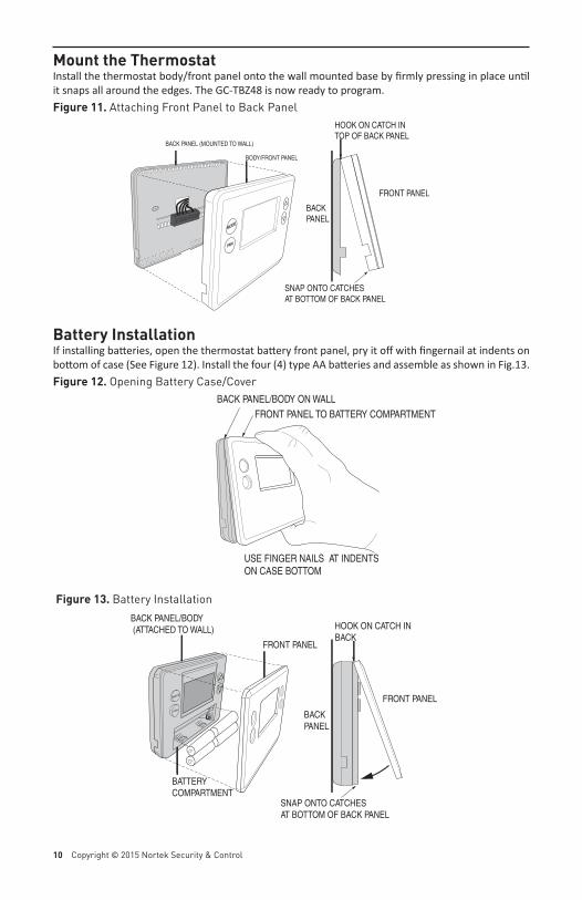
Mount the Thermostat Install the thermostat body/front panel onto the wall mounted base by fi rmly pressing in place un l it snaps all around the edges. The GC-TBZ48 is now ready to program. Figure 11. Attaching Front Panel to Back Panel
Battery InstallationIf installing ba eries, open the thermostat ba ery front panel, pry it off with fi ngernail at indents on bo om of case (See Figure 12). Install the four (4) type AA ba eries and assemble as shown in Fig.13.Figure 12. Opening Battery Case/Cover
Figure 13. Battery Installation
MODEMODE
FANFAN
BODY/FRONT PANEL
BACK PANEL (MOUNTED TO WALL)
HOOK ON CATCH INTOP OF BACK PANEL
SNAP ONTO CATCHESAT BOTTOM OF BACK PANEL
FRONT PANEL
BACK PANEL
MODE
FAN
BACK PANEL/BODY (ATTACHED TO WALL)
FRONT PANEL
BATTERYCOMPARTMENT
HOOK ON CATCH INBACK
SNAP ONTO CATCHESAT BOTTOM OF BACK PANEL
FRONT PANEL
BACK PANEL
USE FINGER NAILS AT INDENTSON CASE BOTTOM
BACK PANEL/BODY ON WALLFRONT PANEL TO BATTERY COMPARTMENT
Copyright © 2015 Nortek Security & Control LLC 11
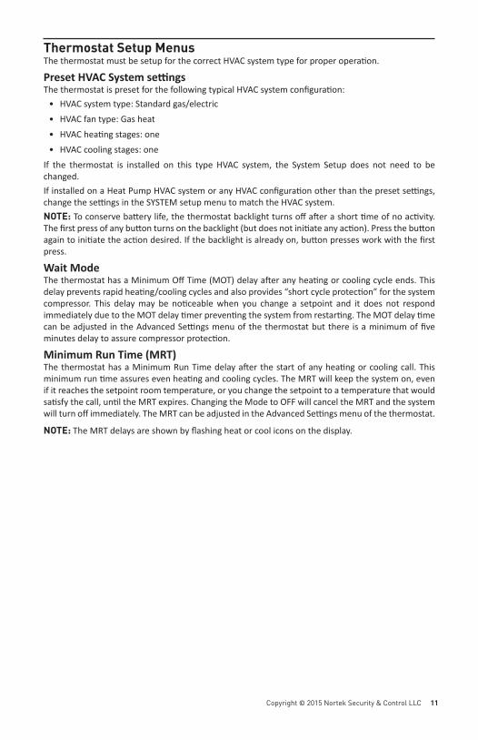
Thermostat Setup MenusThe thermostat must be setup for the correct HVAC system type for proper opera on.
Preset HVAC System se ngsThe thermostat is preset for the following typical HVAC system confi gura on:
• HVAC system type: Standard gas/electric• HVAC fan type: Gas heat• HVAC hea ng stages: one• HVAC cooling stages: one
If the thermostat is installed on this type HVAC system, the System Setup does not need to be changed. If installed on a Heat Pump HVAC system or any HVAC confi gura on other than the preset se ngs, change the se ngs in the SYSTEM setup menu to match the HVAC system.NOTE: To conserve ba ery life, the thermostat backlight turns off a er a short me of no ac vity. The fi rst press of any bu on turns on the backlight (but does not ini ate any ac on). Press the bu on again to ini ate the ac on desired. If the backlight is already on, bu on presses work with the fi rst press.
Wait Mode The thermostat has a Minimum Off Time (MOT) delay a er any hea ng or cooling cycle ends. This delay prevents rapid hea ng/cooling cycles and also provides “short cycle protec on” for the system compressor. This delay may be no ceable when you change a setpoint and it does not respond immediately due to the MOT delay mer preven ng the system from restar ng. The MOT delay me can be adjusted in the Advanced Se ngs menu of the thermostat but there is a minimum of fi ve minutes delay to assure compressor protec on.
Minimum Run Time (MRT)The thermostat has a Minimum Run Time delay a er the start of any hea ng or cooling call. This minimum run me assures even hea ng and cooling cycles. The MRT will keep the system on, even if it reaches the setpoint room temperature, or you change the setpoint to a temperature that would sa sfy the call, un l the MRT expires. Changing the Mode to OFF will cancel the MRT and the system will turn off immediately. The MRT can be adjusted in the Advanced Se ngs menu of the thermostat.
NOTE: The MRT delays are shown by fl ashing heat or cool icons on the display.
12 Copyright © 2015 Nortek Security & Control
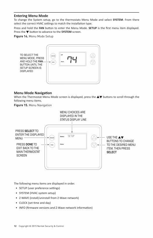
Entering Menu Mode To change the System setup, go to the thermostats Menu Mode and select SYSTEM. From there select the correct HVAC se ngs to match the installa on type.Press and hold the FAN bu on to enter the Menu Mode. SETUP is the fi rst menu item displayed. Press the � bu on to advance to the SYSTEM screen.Figure 14. Menu Mode Setup
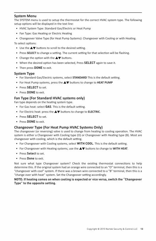
Menu Mode Naviga onWhen the Thermostat Menu Mode screen is displayed, press the �� bu ons to scroll through the following menu items.Figure 15. Menu Navigation
The following menu items are displayed in order.• SETUP (user preference se ngs)• SYSTEM (HVAC system setup)• Z-WAVE (install/uninstall from Z-Wave network)• CLOCK (set me and day)• INFO (fi rmware versions and Z-Wave network informa on)
MODE
FAN
Select
Done
Setup
PRESS DONE TOEXIT BACK TO THEMAIN THERMOSTATSCREEN
PRESS SELECT TOENTER THE DISPLAYEDMENU
MENU CHOICES AREDISPLAYED IN THE STATUS DISPLAY LINE
USE THE ��BUTTONS TO CHANGETO THE DESIRED MENUITEM, THEN PRESSSELECT
MODE
FAN 74Off
Auto
TO SELECT THE MENU MODE, PRESSAND HOLD THE FANBUTTON UNTIL THESETUP SCREEN ISDISPLAYED
Copyright © 2015 Nortek Security & Control LLC 13
System Menu The SYSTEM menu is used to setup the thermostat for the correct HVAC system type. The following setup op ons will be displayed in the text line:
• HVAC System Type: Standard Gas/Electric or Heat Pump• Fan Type: Gas Hea ng or Electric Hea ng• Changeover Valve Type (for Heat Pump Systems): Changeover with Cooling or with Hea ng.
To select op ons:• Use the �� bu ons to scroll to the desired se ng. • Press SELECT to change a se ng. The current se ng for that selec on will be fl ashing.• Change the op on with the �� bu ons. • When the desired op on has been selected, Press SELECT again to save it. • Then press DONE to exit.
System Type• For Standard Gas/Electric systems, select STANDARD This is the default se ng. • For Heat Pump systems, press the �� bu ons to change to HEAT PUMP • Press SELECT to set.• Press DONE to exit.
Fan Type (For Standard HVAC systems only) Fan type depends on the hea ng system type.
• For Gas heat: select GAS. This is the default se ng. • For Electric heat: press the �� bu ons to change to ELECTRIC. • Press SELECT to set.• Press DONE to exit.
Changeover Type (For Heat Pump HVAC Systems Only) The changeover (or reversing) valve is used to change from hea ng to cooling opera on. The HVAC system is either a Changeover with Cooling type (O) or Changeover with Hea ng type (B). Most are changeover with cooling, which is the default se ng.
• For Changeover with Cooling systems, select WITH COOL. This is the default se ng. • For Changeover with Hea ng systems, use the �� bu ons to change to WITH HEAT. • Press Select to set.• Press Done to exit.
Not sure what type Changeover system? Check the exis ng thermostat connec ons to help determine this. If the original system had an orange wire connected to an “O” terminal, then this is a “changeover with cool” system. If there was a brown wire connected to a “B” terminal, then this is a “change over with heat” system. Set the Changeover se ng accordingly. NOTE: If heating comes on when cooling is expected or vice versa, switch the “Changeover Type” to the opposite setting.
14 Copyright © 2015 Nortek Security & Control
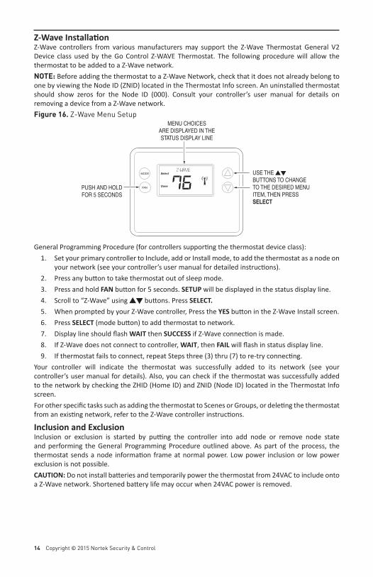
Z-Wave Installa onZ-Wave controllers from various manufacturers may support the Z-Wave Thermostat General V2 Device class used by the Go Control Z-WAVE Thermostat. The following procedure will allow the thermostat to be added to a Z-Wave network.NOTE: Before adding the thermostat to a Z-Wave Network, check that it does not already belong to one by viewing the Node ID (ZNID) located in the Thermostat Info screen. An uninstalled thermostat should show zeros for the Node ID (000). Consult your controller’s user manual for details on removing a device from a Z-Wave network.Figure 16. Z-Wave Menu Setup
General Programming Procedure (for controllers suppor ng the thermostat device class):1. Set your primary controller to Include, add or Install mode, to add the thermostat as a node on
your network (see your controller’s user manual for detailed instruc ons).2. Press any bu on to take thermostat out of sleep mode.3. Press and hold FAN bu on for 5 seconds. SETUP will be displayed in the status display line. 4. Scroll to “Z-Wave” using �� bu ons. Press SELECT.5. When prompted by your Z-Wave controller, Press the YES bu on in the Z-Wave Install screen.6. Press SELECT (mode bu on) to add thermostat to network.7. Display line should fl ash WAIT then SUCCESS if Z-Wave connec on is made.8. If Z-Wave does not connect to controller, WAIT, then FAIL will fl ash in status display line.9. If thermostat fails to connect, repeat Steps three (3) thru (7) to re-try connec ng.
Your controller will indicate the thermostat was successfully added to its network (see your controller’s user manual for details). Also, you can check if the thermostat was successfully added to the network by checking the ZHID (Home ID) and ZNID (Node ID) located in the Thermostat Info screen.For other specifi c tasks such as adding the thermostat to Scenes or Groups, or dele ng the thermostat from an exis ng network, refer to the Z-Wave controller instruc ons.
Inclusion and ExclusionInclusion or exclusion is started by pu ng the controller into add node or remove node state and performing the General Programming Procedure outlined above. As part of the process, the thermostat sends a node informa on frame at normal power. Low power inclusion or low power exclusion is not possible.CAUTION: Do not install ba eries and temporarily power the thermostat from 24VAC to include onto a Z-Wave network. Shortened ba ery life may occur when 24VAC power is removed.
MODE
FAN
Select
Done
z-wave USE THE ��BUTTONS TO CHANGETO THE DESIRED MENUITEM, THEN PRESSSELECT
MENU CHOICESARE DISPLAYED IN THESTATUS DISPLAY LINE
PUSH AND HOLDFOR 5 SECONDS
76
Copyright © 2015 Nortek Security & Control LLC 15
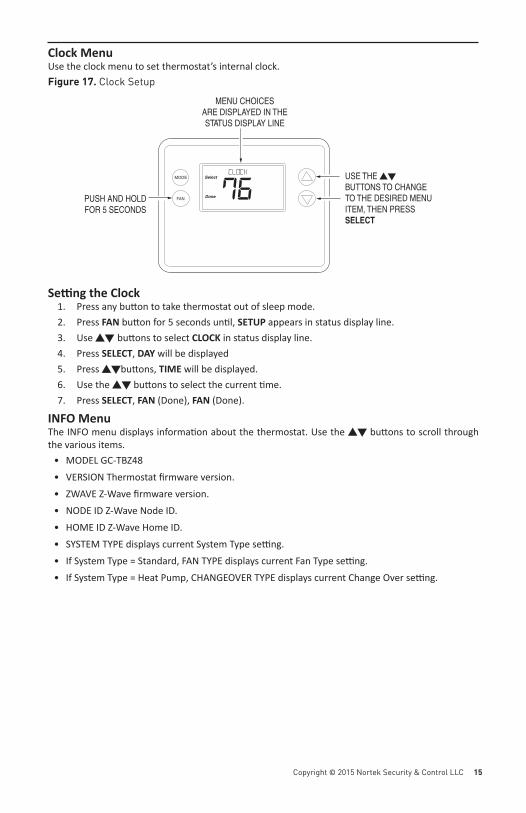
Clock MenuUse the clock menu to set thermostat’s internal clock.Figure 17. Clock Setup
Se ng the Clock1. Press any bu on to take thermostat out of sleep mode.2. Press FAN bu on for 5 seconds un l, SETUP appears in status display line.3. Use �� bu ons to select CLOCK in status display line.4. Press SELECT, DAY will be displayed5. Press ��bu ons, TIME will be displayed.6. Use the �� bu ons to select the current me.7. Press SELECT, FAN (Done), FAN (Done).
INFO MenuThe INFO menu displays informa on about the thermostat. Use the �� bu ons to scroll through the various items.
• MODEL GC-TBZ48• VERSION Thermostat fi rmware version.• ZWAVE Z-Wave fi rmware version.• NODE ID Z-Wave Node ID.• HOME ID Z-Wave Home ID.• SYSTEM TYPE displays current System Type se ng.• If System Type = Standard, FAN TYPE displays current Fan Type se ng.• If System Type = Heat Pump, CHANGEOVER TYPE displays current Change Over se ng.
MODE
FAN
Select
Done
CLOCK USE THE ��BUTTONS TO CHANGETO THE DESIRED MENUITEM, THEN PRESSSELECT
MENU CHOICESARE DISPLAYED IN THESTATUS DISPLAY LINE
PUSH AND HOLDFOR 5 SECONDS
76
16 Copyright © 2015 Nortek Security & Control
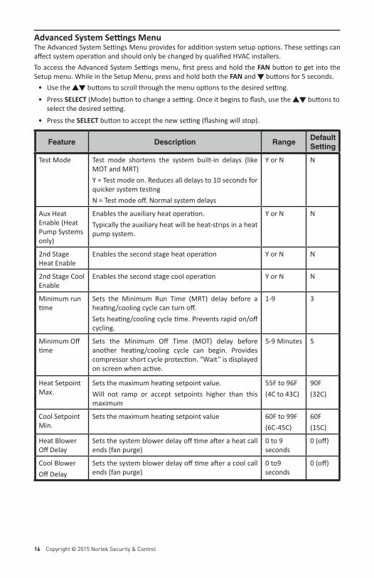
Advanced System Se ngs MenuThe Advanced System Se ngs Menu provides for addi on system setup op ons. These se ngs can aff ect system opera on and should only be changed by qualifi ed HVAC installers.To access the Advanced System Se ngs menu, fi rst press and hold the FAN bu on to get into the Setup menu. While in the Setup Menu, press and hold both the FAN and � bu ons for 5 seconds.
• Use the �� bu ons to scroll through the menu op ons to the desired se ng. • Press SELECT (Mode) bu on to change a se ng. Once it begins to fl ash, use the �� bu ons to
select the desired se ng. • Press the SELECT bu on to accept the new se ng (fl ashing will stop).
Feature Description RangeDefault Setting
Test Mode Test mode shortens the system built-in delays (like MOT and MRT)Y = Test mode on. Reduces all delays to 10 seconds for quicker system tes ngN = Test mode off . Normal system delays
Y or N N
Aux Heat Enable (Heat Pump Systems only)
Enables the auxiliary heat opera on.Typically the auxiliary heat will be heat-strips in a heat pump system.
Y or N N
2nd Stage Heat Enable
Enables the second stage heat opera on Y or N N
2nd Stage Cool Enable
Enables the second stage cool opera on Y or N N
Minimum run me
Sets the Minimum Run Time (MRT) delay before a hea ng/cooling cycle can turn off .Sets hea ng/cooling cycle me. Prevents rapid on/off cycling.
1-9 3
Minimum Off me
Sets the Minimum Off Time (MOT) delay before another hea ng/cooling cycle can begin. Provides compressor short cycle protec on. “Wait” is displayed on screen when ac ve.
5-9 Minutes 5
Heat Setpoint Max.
Sets the maximum hea ng setpoint value.Will not ramp or accept setpoints higher than this maximum
55F to 96F(4C to 43C)
90F (32C)
Cool Setpoint Min.
Sets the maximum hea ng setpoint value 60F to 99F(6C-45C)
60F(15C)
Heat Blower Off Delay
Sets the system blower delay off me a er a heat call ends (fan purge)
0 to 9 seconds
0 (off )
Cool BlowerOff Delay
Sets the system blower delay off me a er a cool call ends (fan purge)
0 to9 seconds
0 (off )
Copyright © 2015 Nortek Security & Control LLC 17
Feature Description RangeDefault Setting
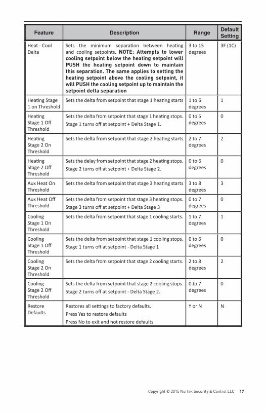
Heat - Cool Delta
Sets the minimum separa on between hea ng and cooling setpoints. NOTE: Attempts to lower cooling setpoint below the heating setpoint will PUSH the heating setpoint down to maintain this separation. The same applies to setting the heating setpoint above the cooling setpoint, it will PUSH the cooling setpoint up to maintain the setpoint delta separation
3 to 15 degrees
3F (1C)
Hea ng Stage 1 on Threshold
Sets the delta from setpoint that stage 1 hea ng starts 1 to 6 degrees
1
Hea ng Stage 1 Off Threshold
Sets the delta from setpoint that stage 1 hea ng stops.Stage 1 turns off at setpoint + Delta Stage 1.
0 to 5 degrees
0
Hea ng Stage 2 On Threshold
Sets the delta from setpoint that stage 2 hea ng starts 2 to 7 degrees
2
Hea ng Stage 2 Off Threshold
Sets the delay from setpoint that stage 2 hea ng stops.Stage 2 turns off at setpoint + Delta Stage 2.
0 to 6 degrees
0
Aux Heat On Threshold
Sets the delta from setpoint that stage 3 hea ng starts 3 to 8 degrees
3
Aux Heat Off Threshold
Sets the delta from setpoint that stage 3 hea ng stops. Stage 3 turns off at setpoint + Delta Stage 3
0 to 7 degrees
0
Cooling Stage 1 On Threshold
Sets the delta from setpoint that stage 1 cooling starts. 1 to 7 degrees
1
Cooling Stage 1 Off Threshold
Sets the delta from setpoint that stage 1 cooling stops.Stage 1 turns off at setpoint - Delta Stage 1
0 to 6 degrees
0
Cooling Stage 2 On Threshold
Sets the delta from setpoint that stage 2 cooling starts. 2 to 8 degrees
2
Cooling Stage 2 Off Threshold
Sets the delta from setpoint that stage 2 cooling stops.Stage 2 turns off at setpoint - Delta Stage 2.
0 to 7 degrees
0
Restore Defaults
Restores all se ngs to factory defaults.Press Yes to restore defaultsPress No to exit and not restore defaults
Y or N N
18 Copyright © 2015 Nortek Security & Control
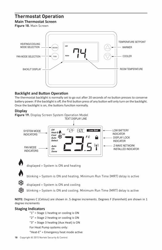
Thermostat OperationMain Thermostat ScreenFigure 18. Main Screen
Backlight and Bu on Opera onThe thermostat backlight is normally set to go out a er 20 seconds of no bu on presses to conserve ba ery power. If the backlight is off , the fi rst bu on press of any bu on will only turn on the backlight. Once the backlight is on, the bu ons func on normally.
DisplayFigure 19. Display Screen System Operation Model
displayed > System is ON and heating
blinking > System is ON and heating. Minimum Run Time (MRT) delay is active
displayed > System is ON and cooling blinking > System is ON and cooling. Minimum Run Time (MRT) delay is active
NOTE: Degrees C (Celsius) are shown in .5 degree increments. Degrees F (Farenheit) are shown in 1 degree increments
Staging Indicators “1” = Stage 1 hea ng or cooling is ON “2” = Stage 2 hea ng or cooling is ON “3” = Stage 3 hea ng (Aux Heat) is ON For Heat Pump systems only: “Heat-E” = Emergency heat mode ac ve
OffHeat-ECoolAutoSelect
AutoOnDone
72F 80c
23.5F C
Low Batt
FAN MODE INDICATORS
SYSTEM MODEINDICATORS
TEXT DISPLAY LINE
LOW BATTERYINDICATORDISPLAY LOCKINDICATOR
Z-WAVE NETWORKINSTALLED INDICATOR
123
MODE
FAN
Off
AutoFAN MODE SELECTION
HEATING/COOLINGMODE SELECTION
TEMPERATURE SETPOINT
WARMER
COOLER74ROOM TEMPERATUREBACKLIT DISPLAY
Copyright © 2015 Nortek Security & Control LLC 19
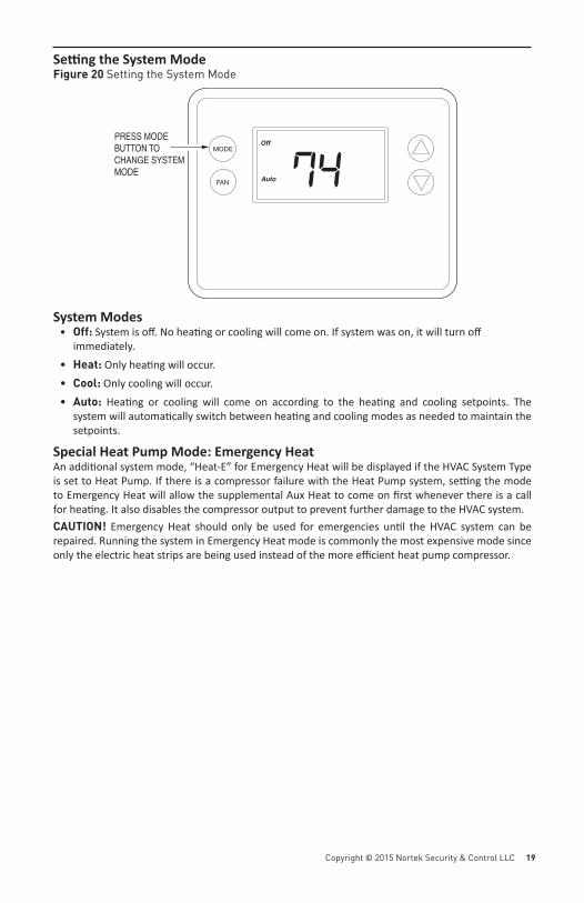
Se ng the System ModeFigure 20 Setting the System Mode
System Modes• Off: System is off . No hea ng or cooling will come on. If system was on, it will turn off
immediately.• Heat: Only hea ng will occur.• Cool: Only cooling will occur.• Auto: Hea ng or cooling will come on according to the hea ng and cooling setpoints. The
system will automa cally switch between hea ng and cooling modes as needed to maintain the setpoints.
Special Heat Pump Mode: Emergency HeatAn addi onal system mode, “Heat-E” for Emergency Heat will be displayed if the HVAC System Type is set to Heat Pump. If there is a compressor failure with the Heat Pump system, se ng the mode to Emergency Heat will allow the supplemental Aux Heat to come on fi rst whenever there is a call for hea ng. It also disables the compressor output to prevent further damage to the HVAC system.CAUTION! Emergency Heat should only be used for emergencies un l the HVAC system can be repaired. Running the system in Emergency Heat mode is commonly the most expensive mode since only the electric heat strips are being used instead of the more effi cient heat pump compressor.
MODE
FAN 74Off
Auto
PRESS MODEBUTTON TO CHANGE SYSTEMMODE
20 Copyright © 2015 Nortek Security & Control
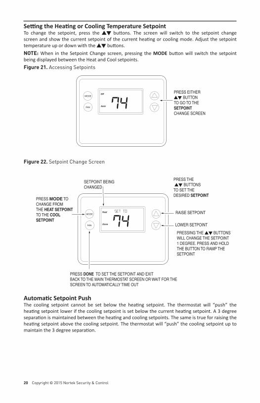
Se ng the Hea ng or Cooling Temperature SetpointTo change the setpoint, press the �� bu ons. The screen will switch to the setpoint change screen and show the current setpoint of the current hea ng or cooling mode. Adjust the setpoint temperature up or down with the �� bu ons.NOTE: When in the Setpoint Change screen, pressing the MODE bu on will switch the setpoint being displayed between the Heat and Cool setpoints.Figure 21. Accessing Setpoints
Figure 22. Setpoint Change Screen
Automa c Setpoint PushThe cooling setpoint cannot be set below the hea ng setpoint. The thermostat will “push” the hea ng setpoint lower if the cooling setpoint is set below the current hea ng setpoint. A 3 degree separa on is maintained between the hea ng and cooling setpoints. The same is true for raising the hea ng setpoint above the cooling setpoint. The thermostat will “push” the cooling setpoint up to maintain the 3 degree separa on.
MODE
FAN 74Off
Auto
PRESS EITHER�� BUTTONTO GO TO THESETPOINT CHANGE SCREEN
MODE
FAN 74Heat
Done
SET to
PRESS THE �� BUTTONS TO SET THE DESIRED SETPOINT
RAISE SETPOINT
LOWER SETPOINT
PRESSING THE �� BUTTONSWILL CHANGE THE SETPOINT 1 DEGREE. PRESS AND HOLD THE BUTTON TO RAMP THE SETPOINT
PRESS MODE TOCHANGE FROMTHE HEAT SETPOINTTO THE COOL SETPOINT
PRESS DONE TO SET THE SETPOINT AND EXITBACK TO THE MAIN THERMOSTAT SCREEN OR WAIT FOR THESCREEN TO AUTOMATICALLY TIME OUT
SETPOINT BEINGCHANGED
Copyright © 2015 Nortek Security & Control LLC 21
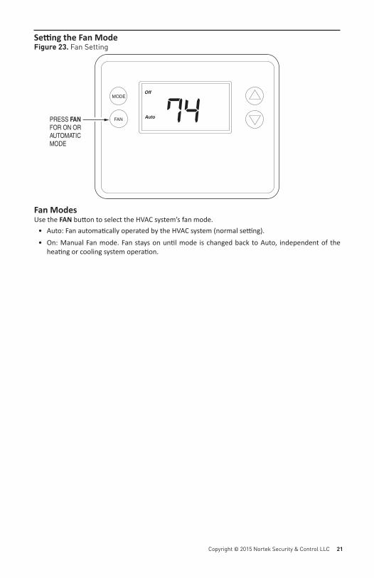
Se ng the Fan ModeFigure 23. Fan Setting
Fan ModesUse the FAN bu on to select the HVAC system’s fan mode.
• Auto: Fan automa cally operated by the HVAC system (normal se ng).• On: Manual Fan mode. Fan stays on un l mode is changed back to Auto, independent of the
hea ng or cooling system opera on.
MODE
FAN 74Off
AutoPRESS FAN FOR ON ORAUTOMATICMODE
22 Copyright © 2015 Nortek Security & Control
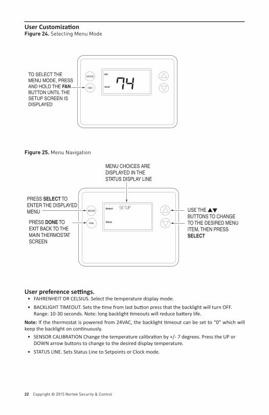
User Customiza onFigure 24. Selecting Menu Mode
Figure 25. Menu Navigation
User preference se ngs.• FAHRENHEIT OR CELSIUS. Select the temperature display mode. • BACKLIGHT TIMEOUT. Sets the me from last bu on press that the backlight will turn OFF.
Range: 10-30 seconds. Note: long backlight meouts will reduce ba ery life.Note: If the thermostat is powered from 24VAC, the backlight meout can be set to “0” which will keep the backlight on con nuously.
• SENSOR CALIBRATION Change the temperature calibra on by +/- 7 degrees. Press the UP or DOWN arrow bu ons to change to the desired display temperature.
• STATUS LINE. Sets Status Line to Setpoints or Clock mode.
MODE
FAN
Select
Done
Setup
PRESS DONE TOEXIT BACK TO THEMAIN THERMOSTATSCREEN
PRESS SELECT TOENTER THE DISPLAYEDMENU
MENU CHOICES AREDISPLAYED IN THE STATUS DISPLAY LINE
USE THE ��BUTTONS TO CHANGETO THE DESIRED MENUITEM, THEN PRESSSELECT
MODE
FAN 74Off
Auto
TO SELECT THE MENU MODE, PRESSAND HOLD THE FANBUTTON UNTIL THESETUP SCREEN ISDISPLAYED
Copyright © 2015 Nortek Security & Control LLC 23
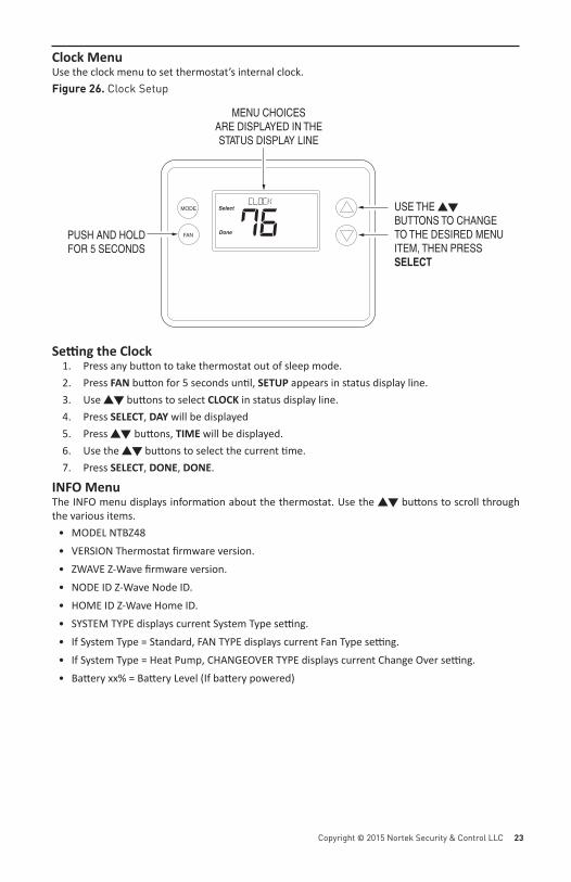
Clock MenuUse the clock menu to set thermostat’s internal clock.Figure 26. Clock Setup
Se ng the Clock1. Press any bu on to take thermostat out of sleep mode.2. Press FAN bu on for 5 seconds un l, SETUP appears in status display line.3. Use �� bu ons to select CLOCK in status display line.4. Press SELECT, DAY will be displayed5. Press �� bu ons, TIME will be displayed.6. Use the �� bu ons to select the current me.7. Press SELECT, DONE, DONE.
INFO MenuThe INFO menu displays informa on about the thermostat. Use the �� bu ons to scroll through the various items.
• MODEL NTBZ48• VERSION Thermostat fi rmware version.• ZWAVE Z-Wave fi rmware version.• NODE ID Z-Wave Node ID.• HOME ID Z-Wave Home ID.• SYSTEM TYPE displays current System Type se ng.• If System Type = Standard, FAN TYPE displays current Fan Type se ng.• If System Type = Heat Pump, CHANGEOVER TYPE displays current Change Over se ng.• Ba ery xx% = Ba ery Level (If ba ery powered)
MODE
FAN
Select
Done
CLOCK USE THE ��BUTTONS TO CHANGETO THE DESIRED MENUITEM, THEN PRESSSELECT
MENU CHOICESARE DISPLAYED IN THESTATUS DISPLAY LINE
PUSH AND HOLDFOR 5 SECONDS
76
24 Copyright © 2015 Nortek Security & Control
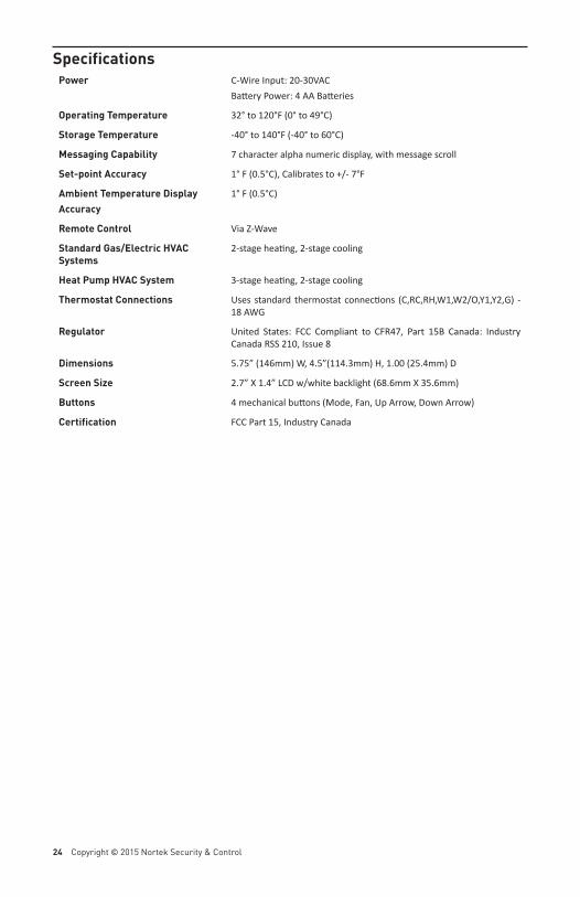
SpecificationsPower C-Wire Input: 20-30VAC
Ba ery Power: 4 AA Ba eries
Operating Temperature 32° to 120°F (0° to 49°C)
Storage Temperature -40° to 140°F (-40° to 60°C)
Messaging Capability 7 character alpha numeric display, with message scroll
Set-point Accuracy 1° F (0.5°C), Calibrates to +/- 7°F
Ambient Temperature DisplayAccuracy
1° F (0.5°C)
Remote Control Via Z-Wave
Standard Gas/Electric HVAC Systems
2-stage hea ng, 2-stage cooling
Heat Pump HVAC System 3-stage hea ng, 2-stage cooling
Thermostat Connections Uses standard thermostat connec ons (C,RC,RH,W1,W2/O,Y1,Y2,G) - 18 AWG
Regulator United States: FCC Compliant to CFR47, Part 15B Canada: Industry Canada RSS 210, Issue 8
Dimensions 5.75” (146mm) W, 4.5”(114.3mm) H, 1.00 (25.4mm) D
Screen Size 2.7” X 1.4” LCD w/white backlight (68.6mm X 35.6mm)
Buttons 4 mechanical bu ons (Mode, Fan, Up Arrow, Down Arrow)
Certification FCC Part 15, Industry Canada
Copyright © 2015 Nortek Security & Control LLC 25
Regulatory InformationFCC ID: WIBTZW011This device complies with Part 15 of the FCC Rules. Opera on is subject to the following two condi ons: (1) This device may not cause harmful interference, and (2) This device must accept any interference received, including interference that may cause undesired opera on.This equipment has been tested and found to comply with the limits for Class B Digital Device, pursuant to Part 15 of the FCC Rules. These limits are designed to provide reasonable protec on against harmful interference in a residen al installa on. This equipment generates and can radiate radio frequency energy and, if not installed and used in accordance with the instruc ons, may cause harmful interference to radio communica ons. However, there is no guarantee that interference will not occur in a par cular installa on. If this equipment does cause harmful interference to radio or television recep on, which can be determined by turning the equipment off and on, the user is encouraged to try to correct the interference by one or more of the following measures.
• Reorient or relocate the receiving antenna• Increase the separa on between the equipment and receiver• Connect the equipment into an outlet on a circuit diff erent from that to which the receiver is
connected• Consult the dealer or an experienced radio/TV technician for help
Any changes or modifi ca ons not expressly approved by the party responsible for compliance could void the user’s authority to operate the equipment.
Industry Canada NoticesIC: 9374A-TBZ48This device complies with Industry Canada license-exempt RSS standard(s). Opera on is subject to the following two condi ons: (1) this device may not cause interference, and (2) this device must accept any interference, including interference that may cause undesired opera on of the device.Le présent appareil est conforme aux CNR d’Industrie Canada applicables aux appareils radio exempts de licence. L’exploita on est autorisée aux deux condi ons suivantes : (1) l’appareil ne doit pas produire de brouillage, et (2) l’u lisateur de l’appareil doit accepter tout brouillage radioélectrique subi, même si le brouillage est suscep ble d’encomprome re le fonc onnement.
Limited WarrantyThis Nortek Security & Control LLC product is warranted against defects in material and workmanship for one (1) year. This warranty extends only to wholesale customers who buy direct from Nortek Security & Control or through Nortek Security & Control normal distribu on channels. Nortek Security & Control does not warrant this product to consumers. Consumers should inquire from their selling dealer as to the nature of the dealer’s warranty, if any.There are no obliga ons or liabili es on the part of Nortek Security & Control for consequen al damages arising out of or in connec on with use or performance of this product or other indirect damages with respect to loss of property, revenue, or profi t, or cost of removal, installa on, or reinstalla on. All implied warran es for func onality, are valid only un l the warranty expires. This Nortek Security & Control Warranty is in lieu of all other warran es express or implied.
10006516 A
Go Control1950 Camino Vida Roble, Suite 150Carlsbad, CA 92008 USAFor technical support in the USA and Canada:Dial: 855-2GIG-TECH (855-244-4832)Email : [email protected] website for technical support hours of operationFor technical support outside of the USA and Canada:Contact your regional distributorVisit www.2GIG.com or dealer.2gig.com technical support hours of operation