Embed Size (px)
Citation preview
J. Gulliksen et al. (Eds.): EIS 2007, LNCS 4940, pp. 158–174, 2008.
Model-Driven Prototyping for Corporate Software Specification
Thomas Memmel1, Carsten Bock2, and Harald Reiterer1
1 Human-Computer Interaction Lab, University of Konstanz, Germany {memmel,reiterer}@inf.uni-konstanz.de
2 Dr. Ing. h.c. F. Porsche AG, Germany
Abstract. Corporate software development faces very demanding challenges, especially concerning the design of user interfaces. Collaborative design with stakeholders demands modeling methods that everybody can understand and apply. But when using traditional, paper-based methods to gather and document requirements, an IT organization often experiences frustrating communication issues between the business and development teams. We present ways of im-plementing model-driven prototyping for corporate software development. Without harming agile principles and practice, detailed prototypes can be em-ployed for collaborative design. Model-driven prototyping beats a new path to-wards visual specifications and the substitution of paper-based artifacts.
Keywords: Prototyping, model-driven user interface design, UI specification, corporate software development, agile modeling.
1 Introduction
From the authors’ experience with the automotive industry, we see that many companies strive to further increase their influence on the user interface design (UID) of corporate software systems. The risk of bad user interface (UI) design and usability is considerable, and it is an economic risk. But integrating usability engineering (UE) often causes con-flicts with other stakeholders and faces shrinking IT budgets and pressure of time.
Several ingredients can therefore contribute to development failure: the increasing importance of the UI in the overall system, the separation of professions, particularly software engineering (SE) and UE, and consequently a lack of methods, tools and process models that integrate the UE knowledge of the UI expert with that of the software engineer and other stakeholders. All issues must be addressed from the very beginning, when the software systems are defined. Consequently, new approaches to requirements engineering (RE) and specification practice are necessary.
In this article we introduce a model-driven prototyping approach to the development of interactive corporate software systems. By employing prototypes as vehicles for both design and system specification, we are able to bridge existing gaps while making the overall design process more efficient and effective, resulting in lower development costs, but improved software quality. Simultaneously we address the different require-ments of stakeholders by offering different levels of abstraction and formality.
In Section 2 we summarize the importance of UID for corporate software develop-ment and point out the various challenges that automotive engineering processes have to
© Springer-Verlag Berlin Heidelberg 2008
The original version of this chapter was revised: The copyright line was incorrect. This has beencorrected. The Erratum to this chapter is available at DOI: 10.1007/978-3-540-92698-6_37
Model-Driven Prototyping for Corporate Software Specification 159
face. We contrast the demands with the current shortcomings of wide-spread RE prac-tice and propose a change of applied practice. In Section 3, we show how SE and UE can be bounded through changing the RE up-front, and how requirement specification takes place. We outline the interdisciplinary usage of prototyping and encourage an extended role for prototyping during RE. In Section 4, the resulting design approach is compared with the principles and practice of agile software development. We discuss in detail why the extension of the RE phase is still compatible with agile development. Consequently, in Section 5 we present our concept of a model-driven tailored tool sup-port for developing prototyping-based specifications of interactive systems. We summa-rize our experiences and lessons learned in Section 6.
2 Corporate Software Development
The UI is the part of the software that can help users to work more efficiently and effectively. When users are unable to perform their tasks, the usage of the software may be entirely incorrect, slow to make progress, and may finally lead to reduced acceptance. With corporate software, the UI transports important (emotional) values such as corporate design (CD) and corporate identity (CI). In the automotive industry, a wide range of different software systems is available to the customer. For example, a company website is necessary to create brand awareness, transport product values, enable product search and configuration, allow contact to nearby retailers, and finally to increase customer loyalty. But in this article we concentrate on the development of in-car information systems. Such systems are intended to support the driver during traveling, e.g. with GPS navigation or dynamic traffic information. Such systems must never compromise road safety [1] and the respective UIs must be intuitive and easy to use. Embedded systems play an important role in the market success of an automotive brand and the customer acceptance of its products [2].
2.1 Challenges for Corporate Engineering Processes
As well as the implementation of pure functionality, corporate software products demand the integration of usability and design consideration into the development process. This frequently conflicts with strict timelines, leading to coding being started prematurely, while system requirements are still vague or unknown. Typical SE and UE processes lack flexibility and adaptability when facing changing requirements, which results in increased complexity and costs.
Consequently, many companies became receptive to agile methods of SE and UE. Agile methods travel in a light-weight fashion along the software lifecycle and due to less documentation, more communication, sharing of code and models, and special programming methods etc., they successfully address many issues of corporate soft-ware development. On the other hand, agile methods do not provide room for typical UE and UID and need to be extended by a certain degree of design and usability ex-pertise that is integrated into the methods and tools applied.
2.2 Shortcomings of Current Requirements Engineering Practice
UE usually documents design knowledge in style guides that can easily reach a size of hundreds of pages and require hundreds of hours of effort. But written language is
160 T. Memmel, C. Bock, and H. Reiterer
ambiguous and the lack of visual cues leaves room for misinterpretation. Especially when interactive behavior has to be specified, a picture is worth a thousand words and “[…], the worst thing that any project can do is attempt to write a natural language specification for a user interface” [3].
In a survey of ergonomists, designers and technical experts, we found that a major-ity of stakeholders use typical office software products for the specification of auto-motive software systems [4]. This is caused by the difficulty of customizing or even building CASE-tools [5] and, more importantly, by their poor usability [6]. But as with the use of natural language, employing applications such as Microsoft Power-Point, Word, Excel or Visio does also highlight critical shortcomings for engineering interactive systems. First of all, stakeholders choose their favorite software applica-tion independently and according to their individual preferences. This inevitably leads to a wide variety of formats that often cannot be interchanged without loss of preci-sion or editability. Secondly, those who are responsible for actually coding the soft-ware system will use completely different tools during the implementation process. Consequently, the effort invested in drawing PowerPoint slides or Excel sheets does not help programming of the final system. Virtual prototypes cannot automatically be created from such specifications with justifiable effort [4].
But prototyping is necessary to provide rapid feedback and to guide the overall speci-fication process towards an ultimate design solution [7]. The participation of non-technical personnel inevitably leads to the demand for a common modeling language throughout the lifecycle. Otherwise, stakeholders may think they all agree on a design, only to discover down the line that they had very different expectations and behaviors in mind. Hence, there is a need to have one common denominator of communication.
3 Prototyping for Visual Specification
The Volere RE process outlines the most important activities for system specification [8]. This includes trawling for requirements, and their separation into functional (e.g. data structures, data models, algorithms, error handling, behavior) and non-functional (e.g. reliability, safety, processing time, compliance with guidelines and regulations, usability, look and feel) requirements. This categorization of requirements also mir-rors the different competencies of SE and UE.
3.1 The Interaction Layer: Where SE and UE Meet
Software engineers are generally trained in topics such as system architecture or data-base design, while usability engineers are concerned with e.g. ease of use, ease of learning, user performance, user satisfaction and aesthetics. A usability expert nor-mally has a black box view of the back-end system, while the software engineer has a deeper understanding of the architecture and code behind the UI [9]. Although both disciplines have reached a certain degree of maturity, they are still practiced very independently [10]. Consequently, usability engineers and software developers, as well as (interaction) designers, end-users and business personnel express themselves in quite different fashions, ranging from informal documents (e.g. scenarios) to for-mal models (e.g. UML).
Model-Driven Prototyping for Corporate Software Specification 161
However, the behavior of the system and the feel of the UI are very much depend-ant on each other. The more important the UI component becomes for a software application, the more significant is its impact on the back-end system. Hence, SE and UE need to overlap at the interaction layer in order to develop usable systems. If the collaboration at the interaction layer is well defined and working successfully, “the time to market can be dramatically shortened by (having) well defined interaction points for the teams to re-sync and communicate” [11].
3.2 Prototyping for the Visual Specification of Interactive Systems
The Volere RE process employs (throw-away) prototypes as vehicles for require-ments elicitation [8]. SE recognizes prototyping as a method for inspections, testing and incremental development. HCI uses prototypes mainly for participatory design (PD). Prototypes are an “excellent means for generating ideas about how a UI can be designed and it helps to evaluate the quality of a solution at an early stage” [12]. Pro-totypes can therefore be boundary objects for SE, UE and other stakeholders as they are a common language to which all can relate [11, 12, 13].
With Volere, the purpose of prototypes is restricted to requirements gathering. Af-ter the requirements have been written down and forwarded to the quality gateway, they are still documented in a paper-based requirements specification. This is exactly where room for interpretation emerges and where misinterpretations can lead to mis-understandings and cause expensive late-cycle changes. Hence, the role of prototyp-ing must be extended and the visual expressiveness of prototypes must be anchored in corporate software specification processes.
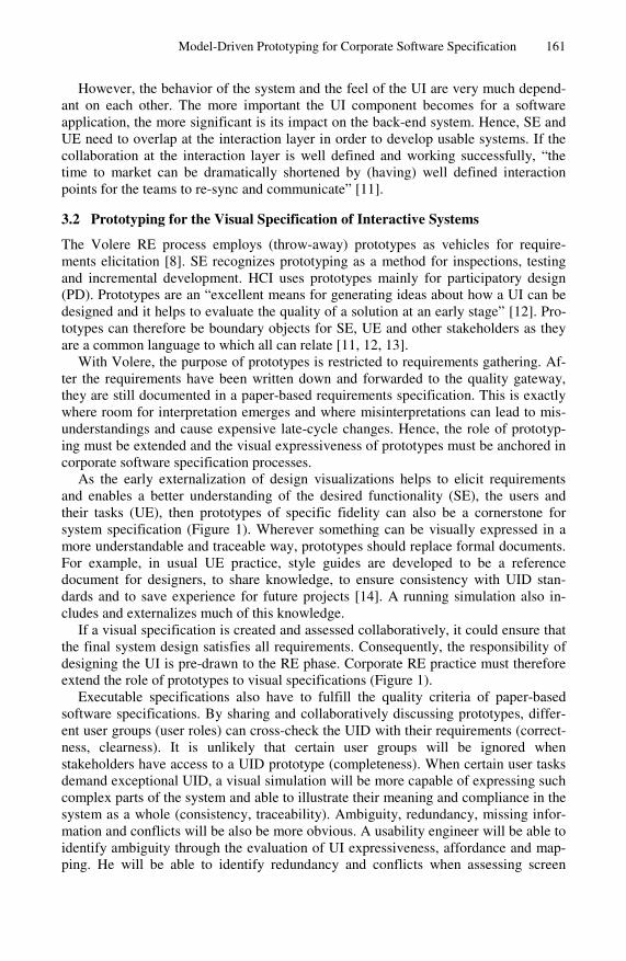
As the early externalization of design visualizations helps to elicit requirements and enables a better understanding of the desired functionality (SE), the users and their tasks (UE), then prototypes of specific fidelity can also be a cornerstone for system specification (Figure 1). Wherever something can be visually expressed in a more understandable and traceable way, prototypes should replace formal documents. For example, in usual UE practice, style guides are developed to be a reference document for designers, to share knowledge, to ensure consistency with UID stan-dards and to save experience for future projects [14]. A running simulation also in-cludes and externalizes much of this knowledge.
If a visual specification is created and assessed collaboratively, it could ensure that the final system design satisfies all requirements. Consequently, the responsibility of designing the UI is pre-drawn to the RE phase. Corporate RE practice must therefore extend the role of prototypes to visual specifications (Figure 1).
Executable specifications also have to fulfill the quality criteria of paper-based software specifications. By sharing and collaboratively discussing prototypes, differ-ent user groups (user roles) can cross-check the UID with their requirements (correct-ness, clearness). It is unlikely that certain user groups will be ignored when stakeholders have access to a UID prototype (completeness). When certain user tasks demand exceptional UID, a visual simulation will be more capable of expressing such complex parts of the system and able to illustrate their meaning and compliance in the system as a whole (consistency, traceability). Ambiguity, redundancy, missing infor-mation and conflicts will be also be more obvious. A usability engineer will be able to identify ambiguity through the evaluation of UI expressiveness, affordance and map-ping. He will be able to identify redundancy and conflicts when assessing screen
162 T. Memmel, C. Bock, and H. Reiterer
Fig. 1. Requirements engineering for visual specification, based on [8]
spacing, layout or navigation structure. The absence of specific information will attract attention through “white spots” on the screen or missing visual components. With interac-tive and expressive prototypes, interaction and functional issues can be addressed sooner and the identification of usability requirements can be done as soon as the early stages of design [15] and before coding starts (Figure 1). Unnecessary system functionality can be identified through UI evaluation methods rather than by reading through text. All in all, a visual requirements specification can be assessed more easily and to some extent the crea-tion of a prototype (pilot system) proves the convertibility of the UID into a final system.
Prototyping can significantly reduce the effort on the programming side as well: to build the UI of a system with the help of a running simulation (prototype) is much easier than doing it from scratch based on textual descriptions. A developer can quickly look at the simulation in order to get a visual impression of the requirements. Moreover, when the creation of prototypes takes place in a model-driven engineering process, this results in further advantages for the RE process. Models can imply con-straints and can carry forward standards and design rules. Once properly defined, they can be externalized by different representations and in a different level of abstraction and formality. On the one hand, this eases access for different stakeholders. On the other hand, while a running simulation is the visual outcome, the underlying models capture design knowledge and decisions. Consequently, we encourage a model-driven approach that employs prototypes as media of communication.
Model-Driven Prototyping for Corporate Software Specification 163
4 Compliance with Agile Software Development
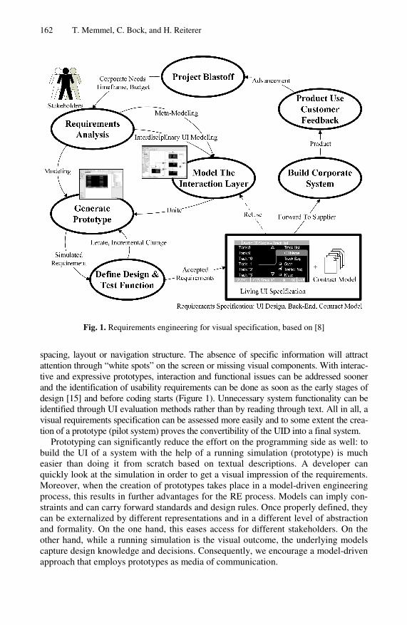
Before presenting our model-driven prototyping approach, we want to outline its com-pliance with agile environments. At first sight, adding up-front visual specification activity does appear to contradict agile software development: agile software lifecycles, e.g. their most popular representative Extreme Programming (XP) [16], encourage
UI Spike
Architectural Spike
Release Planning
IterationAcceptance & Usability Tests
SmallRelease
User Stories, Usage ScenariosModel-Based Lo/Hi-Fi Prototyping
Code Spikes& EstimatesMinimal UI Spec
UI Specification
ArchitectureSpecification
EnhancePrototype
Usability Goals & Test Scenarios
(Usability) Bugs
Initial Requirements & Usability Up-Front eXtreme Evaluations
Fig. 2. The XP lifecycle extended by UE methods during up-front and test phase
Table 1. Core principles (excerpt) of agile development, and their compatibility with a model-driven software development approach (http://www.agilemodeling.com)
Agile principle Compatibility with model-driven development Model With A Purpose
Switching between different models allows the origin of a re-quirement to be traced and to understand its design rationale
Multiple Models No single model is sufficient for all software development needs. By providing different modeling layers, several ways of express-ing problems are available
Rapid Feedback A model-driven approach allows a fast transformation of models into assessable, living simulations
Assume Sim-plicity
Models allow an easy cross-checking with actual requirements. Unnecessary requirements can be identified visually
Embrace change Models should allow easy enhancement or change. Changes to an abstract representation layer should have impact on the generation of prototypes and code
Incremental Change
Different layers of detail allow domain-specific access for stake-holders and enable the creation of small models first, more sophis-ticated models later
Software Is Your Primary Goal
The primary goal of software development is to produce code rather than extraneous documentation. A model-driven approach does directly contribute to this goal by enabling fast generation of prototypes and reusable code
164 T. Memmel, C. Bock, and H. Reiterer
Table 2. Core practices of agile development, and their compatibility with a model-driven software development approach (http://www.agilemodeling.com)
Agile Practice Compatibility with model-driven development Active Stakeholder Participation
When different models are provided for different stakeholders, everybody can take part in system specification. Prototypes are a language everybody understands, and the perfect vehicle for discussion
Apply The Right Artifacts
Some modeling languages are inappropriate for describing specific parts of the system. For example, UML is insufficient for describing the UI, but helps in designing the architecture
Create Several Models In Parallel
A model-driven approach allows the parallel development of different models (e.g. regarding disciplines and competencies)
Iterate To Another Artifact
When a specific artifact is unable to express certain parts of the system, one should iterate to other methods of expression
Model in Small Increments
A model-driven approach allows models to be charged with different levels of detail. Small releases can be provided very quickly to get rapid feedback and can be refined later
Model with others A model-driven approach allows a break-up of responsibility. Stakeholders can model according to their expertise. Different models are combined to simulations and code
Model to commu-nicate
To some extent, models need to look attractive for showing them to decision makers. By including a design layer, a model-driven approach can provide system simulations that can be used for discussion and release planning
Model to under-stand
Modeling helps to understand and to explore the problem space. For exploring alternate solutions, you do not need to draw UML or class diagrams. A model-driven approach can provide appropriate modeling languages that support the stake-holders during early stages of design.
Prove it with code A model is an abstraction of whatever you are building. To determine whether it will work, a model-driven approach al-lows the easy generation of prototypes and running code.
Formalize Contract Models
The code that is exported on the basis of the description models can be supported by e.g. an XML DTD. As other design know-ledge and guidance is included as a running simulation, a visual specification is a detailed contract model.
coding from the very beginning. However, interdisciplinary research has agreed that a certain amount of UE and UID up-front is needed in XP, when the UI has great weight. [17] developed a model-driven, usage-centered UE approach. Similar to the idea of model-driven SE, the models of usage-centered design (e.g. user role models, task models, content models) make UID a more traceable and formal activity. Compared to typical UE practice, the suggested models are more light-weight and allow the early definition of a minimalist UI specification. In addition, a supplier can implement the system with less effort, as important parts of the UID are already pre-defined and
Model-Driven Prototyping for Corporate Software Specification 165
evaluated (Figure 1). Consequently, adding an UI spike to agile methods delays the overall system implementation, but only to a limited extent. Figure 2 shows how UID and UI specification can be integrated into XP’s up-front. Additionally, our adjusted XP lifecycle model also envisages “extreme evaluations” [18] at later stages of design.
The bottom-line, using visual specifications will help in cutting down the number of iteration cycles and decrease software development costs, while simultaneously assuring corporate quality and compatibility with agile principles (Table 1) and prac-tice (Table 2).
5 A Model-Driven Tool-Chain for Visual Specification
Based on our experience in corporate RE processes, we have developed a tool-chain for the agile and interdisciplinary specification of interactive automotive in-car infor-mation systems. Our tool-chain helps to bridge identified gaps and links up with the idea of model-driven software development.
5.1 Model-Driven Concepts as a Cornerstone for Structured RE
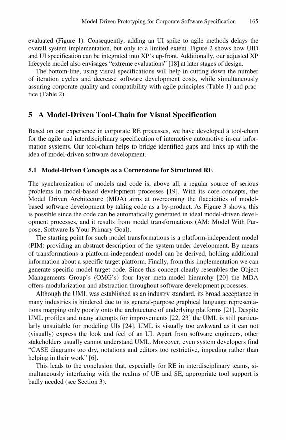
The synchronization of models and code is, above all, a regular source of serious problems in model-based development processes [19]. With its core concepts, the Model Driven Architecture (MDA) aims at overcoming the flaccidities of model-based software development by taking code as a by-product. As Figure 3 shows, this is possible since the code can be automatically generated in ideal model-driven devel-opment processes, and it results from model transformations (AM: Model With Pur-pose, Software Is Your Primary Goal).
The starting point for such model transformations is a platform-independent model (PIM) providing an abstract description of the system under development. By means of transformations a platform-independent model can be derived, holding additional information about a specific target platform. Finally, from this implementation we can generate specific model target code. Since this concept clearly resembles the Object Managements Group’s (OMG’s) four layer meta-model hierarchy [20] the MDA offers modularization and abstraction throughout software development processes.
Although the UML was established as an industry standard, its broad acceptance in many industries is hindered due to its general-purpose graphical language representa-tions mapping only poorly onto the architecture of underlying platforms [21]. Despite UML profiles and many attempts for improvements [22, 23] the UML is still particu-larly unsuitable for modeling UIs [24]. UML is visually too awkward as it can not (visually) express the look and feel of an UI. Apart from software engineers, other stakeholders usually cannot understand UML. Moreover, even system developers find “CASE diagrams too dry, notations and editors too restrictive, impeding rather than helping in their work” [6].
This leads to the conclusion that, especially for RE in interdisciplinary teams, si-multaneously interfacing with the realms of UE and SE, appropriate tool support is badly needed (see Section 3).
166 T. Memmel, C. Bock, and H. Reiterer
ImplementationSpecific Model (ISM) 1
…
Transformation
Transformation
+ TrebleFM+ Balance+ Fader : State
: State
+ select_menuitem(nr_of_menuitem)
<<Function Sound>>
+ Bass FM : Numeric
+ Balance+ Fader+ Dyn. Loudness
: Numeric: Numeric
Platform Independent Model (PIM)
Platform Specific Model (PSM) 1
+ TrebleFM+ Balance+ Fader : Boolean
: Boolean
+ select_menuitem(menuitem_nr)
<<Function Sound>>
+ Bass FM : Integer
+ Balance+ Fader+ Dyn. Loudness
: Integer: Integer
Platform Specific Model (PSM) n
+ TrebleFM+ Balance+ Fader : Boolean
: Boolean
+ select_menuitem(menuitem_nr)
<<Function Sound>>
+ Bass FM : Long Integer
+ Balance+ Fader+ Dyn. Loudness
: Long Integer: Short Integer
Code Platform A
ImplementationSpecific Model (ISM) 2
Code Platform B
ImplementationSpecific Model (ISM) n
Code Platform m…Real world
(M0)
Model(M1)
Metamodel(M2)
OMGArchitecture
<<instanceof>>
<<instanceof>>
Fig. 3. Core models of MDA
5.2 Modularization and Abstraction as a Key for Interdisciplinary Cooperation
When developing interactive graphical systems, close cooperation between team members with different backgrounds, knowledge and experiences is one of the key success factors [25, 26, 27, 28]. As stated in Section 3, a common language is missing today. Although prototypes can be a common denominator for UID at the interaction layer each discipline still needs to employ other (more abstract) modeling languages during development (AM: Iterate To Another Artifact).
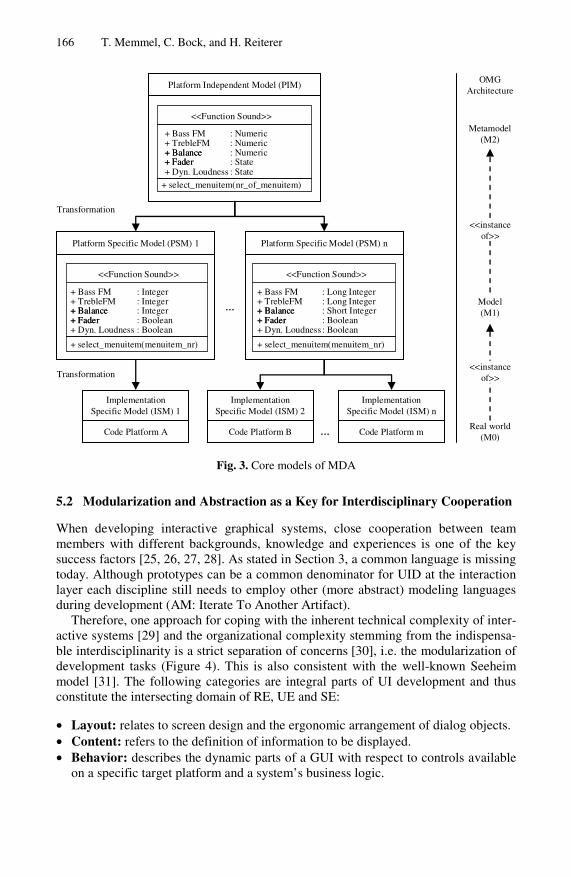
Therefore, one approach for coping with the inherent technical complexity of inter-active systems [29] and the organizational complexity stemming from the indispensa-ble interdisciplinarity is a strict separation of concerns [30], i.e. the modularization of development tasks (Figure 4). This is also consistent with the well-known Seeheim model [31]. The following categories are integral parts of UI development and thus constitute the intersecting domain of RE, UE and SE:
• Layout: relates to screen design and the ergonomic arrangement of dialog objects. • Content: refers to the definition of information to be displayed. • Behavior: describes the dynamic parts of a GUI with respect to controls available
on a specific target platform and a system’s business logic.
Model-Driven Prototyping for Corporate Software Specification 167
Accordingly, in the case of embedded UIs such as automotive driver-information systems, GUI layout is specified by designers and ergonomists. Consequently, con-tents in the form of menu items are provided by technical experts responsible for functional (i.e. hardware) specifications as well as by ergonomists defining menu structures. Finally, system architects or programmers define a system’s behavior, again in close coordination with ergonomists. To some extent, these activities will always take place in parallel (AM: Multiple Models, Model In Parallel). Altogether, ergonomists are propelling and controlling the development process. Furthermore, they are responsible for integrating all artifacts and function as human interface be-tween the competencies and professions of all stakeholders.
Track 8Track 9Track 10Track 11
Track 13
Track List
Track Seq.ScanTraffic Prog.
CD Name
CDS Track 10
Audio CD Single – Track List
12,5°C 19.11.06Mute
Track 12
Track 8Track 9Track 10Track 11
Track 13
Track List
Track Seq.ScanTraffic Prog.
CD Name
CDS Track 10
Audio CD Single – Track List
12,5°C 19.11.06Mute
Track 12
TechnicalExperts
Programmers
Ergonomists
Behavior
MainANTENNE1
D1-Telefon22°C18.04.05
13:12
MainANTENNE1
D1-Telefon22°C24.01.07
13:12
MainANTENNE1
D1-Telefon22°C18.04.05
13:12
MainANTENNE1
D1-Telefon22°C24.01.07
13:12
MainANTENNE1
D1-Telefon22°C18.04.05
13:12
MainANTENNE1
D1-Telefon22°C24.01.07
13:12
MainANTENNE1
D1-Telefon22°C18.04.05
13:12
MainANTENNE1
D1-Telefon22°C24.01.07
13:12
MainANTENNE1
D1-Telefon22°C18.04.05
13:12
MainANTENNE1
D1-Telefon22°C24.01.07
13:12
MainANTENNE1
D1-Telefon22°C18.04.05
13:12
MainANTENNE1
D1-Telefon22°C24.01.07
13:12
MainANTENNE1
D1-Telefon22°C18.04.05
13:12
MainANTENNE1
D1-Telefon22°C24.01.07
13:12
MainANTENNE1
D1-Telefon22°C18.04.05
13:12
MainANTENNE1
D1-Telefon22°C24.01.07
13:12
Nächste 12km
Header
Footer
Menu item 1Menu item 2Menu item 3Menu item 4Menu item 5Menu item 6
Designers
Ergono-mists Ergono-
mists
Layout Content
Human-Machine-Interface
Track 8
Track 9
Track 10
Tack 11
Track 12
Track List
Track Seq.ScanTraffic Prog.
CD Name
CDS Track 10
Audio CD Single – Track List
12,5°C 19.11.06Mute
Track 8
Track 9
Track 10
Tack 11
Track 12
Track List
Track Seq.ScanTraffic Prog.
CD Name
CDS Track 10
Audio CD Single – Track List
12,5°C 19.11.06Mute
Track 8
Track 9
Track 10
Tack 11
Track 12
Track List
Track Seq.ScanTraffic Prog.
CD Name
CDS Track 10
Audio CD Single – Track List
12,5°C 19.11.06Mute
Track 8
Track 9
Track 10
Tack 11
Track 12
Track List
Track Seq.ScanTraffic Prog.
CD Name
CDS Track 10
Audio CD Single – Track List
12,5°C 19.11.06Mute
Fig. 4. Layout, content and behavior as constituent parts of interactive graphical systems
In the realm of UI development, the separate specification of layout, content and be-havior must not take place completely independent and needs to follow certain con-straints (meta-model, Section 5.3) to guarantee compatibility. Changing a specific model (e.g. an abstract one) must consistently affect dependent models (e.g. a more detailed one) and consequently the prototype as well (AM: Embrace Change). For the generation of the UI prototype, the different parts finally have to be integrated (Figure 4, compare Figure 1).
As well as modularization, abstraction also offers further means for coping with technical and organizational complexity. By presenting information at different levels of abstraction, it is possible to provide developers with only the relevant information
168 T. Memmel, C. Bock, and H. Reiterer
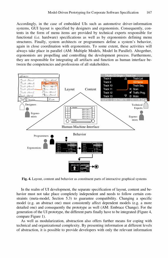
for their specific development tasks (AM: Apply The Right Artifacts). Thus, for working collectively on high-level specifications where contents and the overall sys-tem behavior is specified, developers are provided with a very abstract representation of a state machine by means of visual state charts [32]. These charts only reveal the details necessary for specifying the high-level interaction with the system, the “macro logic”. Developers can therefore connect different menu screens with interaction objects (e.g. rotary knobs, buttons) corresponding to transitions in UML state charts. This presentation must be extraordinarily abstract so that all the developers involved – and, if necessary, even project managers – can understand such high-level specifica-tions (Figure 5).
public classPCMSimulation extends JFrame {private static final long serialVersionUID =-7525227671936685537L;
private static PCMSimulation instance;private HashMap PCMScreenPanels = new HashMap();private JPanel jContentPane = null; // Container for main//drawing area
private JPanel screen = null; // Container for a JFormDesigner//screen
private JButton jButton = null;
public static PCMSimulation getInstance() {return instance;}public HashMap getPCMScreenPanels() {return this.PCMScreenPanels;}public JPanel getMyJContentPane() {return this.jContentPane;}public PCMSimulation() {super();this.instance = this;this.initialize();
}/*** This method initializes jButton** @return javax.swing.JButton */
private JButton getJButton() {if (jButton == null) {jButton = new JButton();jButton.setBounds(new Rectangle(520, 269, 208, 127));...
Zustand 3 Zustand 4
Zustand 2
Start
Zustand 5
State 3 State 4
State 2
Start
State 5
Zustand 3 Zustand 4
Zustand2
Start State 3 State 4
State 2
Start
Platformindependent
model
Platformspecific
model (PSM)
Implemen-tation specificmodel (ISM)
High-level specification
Low-levelspecification
Program-mers
Code
Program-mers
Code
TechnicalExperts
Programmers
Designers
Ergono-mists
TechnicalExperts
Programmers
Fig. 5. Problem- and target group-specific presentation of information
Accordingly, low-level specifications are meant for smaller target groups such as technical experts and programmers. These specifications contain a more detailed system specification. At this level, the behavior of specific widgets (“micro logic”) such as a speller for inputting a navigation destination can explicitly be defined with fully featured state charts and class diagrams. Finally, the code level allows for a rigorous analysis of system features and their implementation, which can only be
Model-Driven Prototyping for Corporate Software Specification 169
conducted by programmers. These abstraction levels correspond to the MDA concepts of PIMs, PSMs and ISMs respectively. Despite this equivalence, model-driven tool support for creating UI specifications at different levels of abstraction is still missing in corporate software development. An approach for creating tailor-made CASE-tools is therefore presented subsequently. This enables clients to take full advantage of model-driven concepts during UI development with interdisciplinary development teams.
5.3 Developing a Model-Driven Tool Chain for UI Specification
In the following, domain-specific modeling is used for creating an individual tool support for UI specification. By leveraging current meta-CASE-tools, for instance MetaEdit+ 4.5, Generic Modeling Environment 5 or Microsoft DSL Tools, this mod-eling approach enables clients to utilize model-driven concepts at affordable time and budget for building tailor-made CASE-tools for any company- and/or project-specific domain. Thus, the procedure for developing a visual domain-specific language (VDSL) that fulfils the aforementioned requirements is described.
The creation of a domain meta-model by the mapping of domain concepts consti-tutes the starting point for developing a specific CASE-tool. Beyond the identification and abstraction of domain concepts, the development of a visual DSL comprises the definition of notations for the graphical representation of domain concepts and the definition of constraints underlying the specification process. For these tasks meta-CASE tools provide a meta-modeling environment that can subsequently also be used as a graphical modeling environment and thereby as a specification instrument for product development in a specific problem domain.
At the beginning, a small team of domain experts collaboratively identifies the es-sential concepts of the problem domain. At this stage, existing requirements docu-ments such as style guides, and particularly the terminology used in daily project work, are analyzed (Figure 1). For instance, in the case of automotive driver-information systems, single menu screens and controls like rotary knobs and pushbut-tons represent the main concepts of the problem domain.
The domain experts can quickly identify these concepts since they are frequently used for product specification. Additionally, the events to which the system should react are included, such as turning and pressing a rotary knob, or pressing and holding a pushbutton. Similarly, all the properties of every single domain concept necessary for specifying driver-information systems are defined.
Later, constraints are added to the meta-model in order to restrict the degrees of freedom for developers in a reasonable way. For instance, the use of some controls is limited to special circumstances. Moreover, constraints are defined that limit the number of subsequent menu screens after selecting a menu item to at most one, en-suring that specifications will be non-ambiguous. Additional constraints could pre-scribe a fixed pushbutton for return actions, for example. It must be stated that the definition of the meta-model therefore determines the overall design space. Conse-quently, the exploration of challenging design alternatives and innovative UID ap-proaches must take place before the meta-model is fixed by the domain experts.
170 T. Memmel, C. Bock, and H. Reiterer
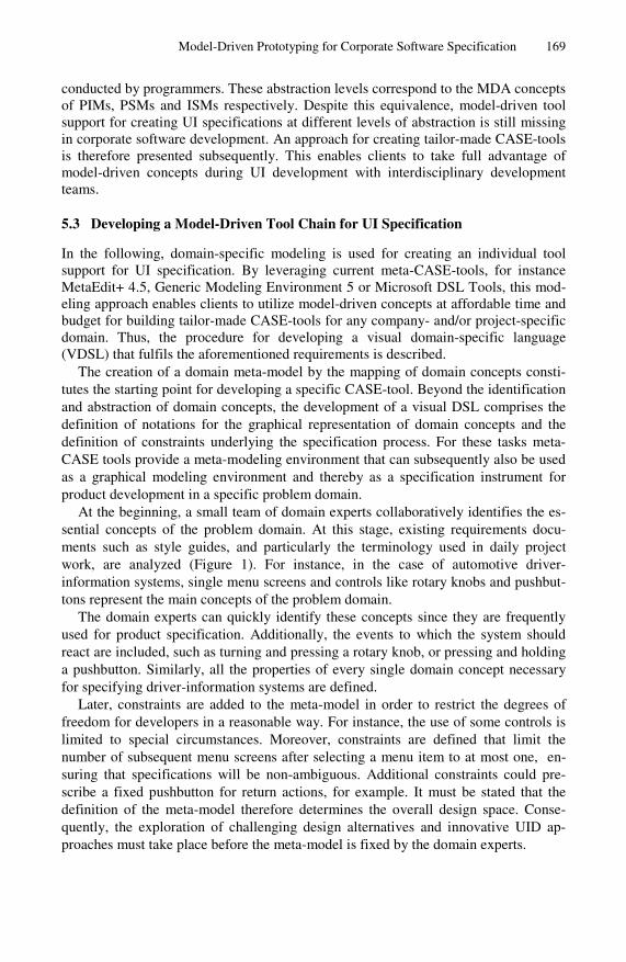
High-level specification
Low-level specification
Fig. 6. Individual CASE-tools for specifying content and behavior of driver-information sys-tems (implemented with MetaEdit+ 4.5)
In a final step, meaningful pictograms are defined for domain concepts in the meta-model, thus allowing for intuitive use by developers during system specification. These self-made symbols clearly resemble the modeled domain concepts. Our experi-ence from a comparison of different specification tools and interviews with develop-ers reveals that especially these individual, domain-specific symbols lead to a very small semantic distance between the specification language and real-word objects of the driver-information system domain. Most notably this strongly increases develop-ers’ acceptance of tailor-made CASE tool [33].
With this DSL, the content and the macro logic of driver-information systems can be specified. In order to also describe the micro logic (see Section 5.2) of widgets, another DSL is developed in exactly the same way as previously illustrated. This DSL enables IT-experts to create UML state charts for detailed UI specifications. These individual CASE tools are shown in Figure 6.
Model-Driven Prototyping for Corporate Software Specification 171
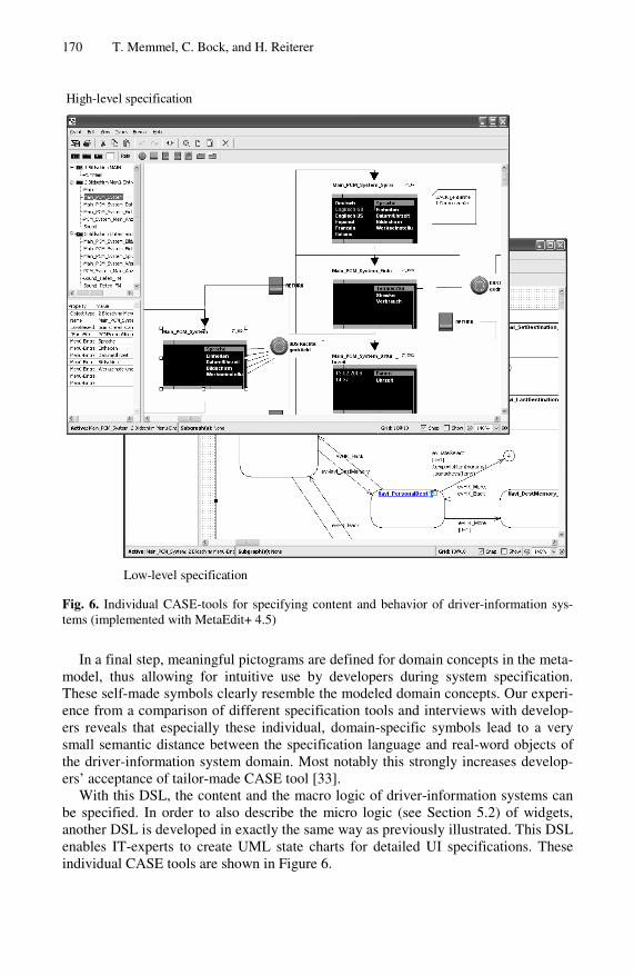
Besides the domain-specific CASE-tools (for modeling the dynamic parts of inter-active systems, i.e. content and behaviour) a domain framework provides the static parts (i.e. a state machine and base widgets) for virtual simulations. Thus for creating virtual simulations from specifications the content and behavior needs to be extracted from the models and linked to the (static) framework. This is done with the help of a code generator enabling developers to create simulations from a specification on the push of a button.
Code generator
Domain-specific CASE-tool:
content
Domain-specific CASE-tool:behaviour
GUI-Builder:
layout
Domain framework
Virtual prototype
Main
ANTENNE1
D1-Telefon
22°C
18.04.05
13:12
Main
ANTENNE1
D1-Telefon
22°C
18.04.05
13:12
Main
ANTENNE1
D1-Telefon
22°C
18.04.05
13:12
Main
ANTENNE1
D1-Telefon
22°C
18.04.05
13:12
Formalspecifi-cation(XML)
Formalspecifi-cation(XML)
Track 8Track 9Track 10Track 11
Track 13
Track List
Track Seq.ScanTraffic Prog.
CD Name
CDS Track 10
Audio CD Single – Track List
12,5°C 19.11.06Mute
Track 12
Track 8Track 9Track 10Track 11
Track 13
Track List
Track Seq.ScanTraffic Prog.
CD Name
CDS Track 10
Audio CD Single – Track List
12,5°C 19.11.06Mute
Track 12
Formalspecifi-cation
(XML)
Designers
Ergonomists
TechnicalExperts
ProgrammersTechnical
Experts
ErgonomistsErgonomists
Fig. 7. Architecture of model-driven UI tool-chain
Finally, for specifying GUI layout designers and ergonomists ideally have to create specifications with a GUI-builder such as JFormdesigner, Expression Interactive Designer (Microsoft) or Aurora XAML Designer (Mobiform) capable of producing GUI descriptions in a XML format. These descriptions can also easily be integrated in the simulation framework by the code generator. The architecture of this tool chain is outlined in Figure 7.
6 Lessons Learned and Conclusion
Our experience reveals that model-driven approaches provide promising concepts for overcoming today’s urgent problems in development processes for corporate software systems. Thus, visual domain-specific languages explicitly capture experts’ knowledge and experience, since this is used for identifying and modeling essential domain con-cepts. With the help of languages created this way, new team members can become
172 T. Memmel, C. Bock, and H. Reiterer
acquainted with company-specific standards more easily and can thus be integrated in interdisciplinary development teams significantly more easily. Moreover, domain-specific modeling, together with the tool chain architecture presented, enables clients to create tailor-made tool support that offers all developers the appropriate level of abstraction for their individual development tasks. Furthermore, problems have to be solved only once at a high level of abstraction and not – as before – once in the imple-mentation level and a second time for documentation. Specifications i.e. requirements engineering can therefore be established as the central backbone of model-driven de-velopment processes, with significant potential for clients and their collaboration with suppliers. If formal, electronic – and thus machine readable – specifications can be exchanged between all stakeholders, the specification problem as well as the commu-nication problem in traditional development processes [27] can be overcome.
In principle, the concepts presented can be adopted for any other domain besides the UID of automotive embedded systems. For instance, a visual domain-specific language could be created for specifying the structure of corporate websites or the information flow in a business process. Despite this flexibility and the potential bene-fits, experience from a pilot project shows that current meta-CASE-tools can be im-proved. In particular, developers would expect interaction patterns from standard office applications e.g. auto layout, grids, object inspectors and tree views for object hierarchies. Additionally, if these tools provided better graphical capabilities, the GUI builder would not have to be integrated via the domain framework and layout could also be specified with a domain-specific language. This would be another important step in reducing complexity in usually heterogeneous IT landscapes.
Overall, meta-modeling offers promising beginnings for a unification of engineer-ing disciplines. As demonstrated with the tool chain presented, this modeling ap-proach is consistent with agile principles and practice. This offers an opportunity for bringing RE, SE and UE closer together, a convergence that is badly needed for cop-ing with the technical and organizational complexity of interdisciplinary and net-worked development processes for corporate software systems.
References
1. Rudin-Brown, C.: Strategies for Reducing Driver Distraction from In-Vehicle Telematics Devices: Report on Industry and Public Consultations, Technical Report No. TP 14409 E,Transport Canada, Road Safety and Motor Vehicle Regulation Directorate (2005) [cited: 21.5.2006], http://www.tc.gc.ca/roadsafety/tp/tp14409/menu.htm
2. Becker, H.P.: Der PC im Pkw: Software zwischen den Welten, automotive electronics sys-tems (3-4), 42–44 (2005)
3. Horrocks, I.: Constructing the user interface with statecharts. Addison-Wesley, Harlow (1999)
4. Bock, C., Zühlke, D.: Model-driven HMI development – Can Meta-CASE tools relieve the pain? In: Proceedings of the First International Workshop on Metamodelling – Utilization in Software Engineering (MUSE), Setúbal, Portugal, September 11, 2006, pp. 312–319 (2006)
5. Isazadeh, H., Lamb, D.A.: CASE Environments and MetaCASE Tools, Technical Report No. 1997-403, Queen’s University [cited: 25.10.2006],
http://www.cs.queensu.ca/TechReports/reports1997.html 6. Jarzabek, S., Huang, R.: The case for user-centered CASE tools. Communications 41(8),
93–99 (1998)
Model-Driven Prototyping for Corporate Software Specification 173
7. Fitton, D., Cheverst, K., Kray, C., Dix, A., Rouncefield, M., Saslis-Lagoudakis, G.: Rapid Prototyping and User-Centered Design of Interactive Display-Based Systems. Pervasive Computing 4(4), 58–66 (2005)
8. Robertson, S., Roberston, J.: Mastering the Requirements Process. Addison-Wesley, Read-ing (2006)
9. Creissac Campos, J.: The modelling gap between software engineering and human-computer interaction. In: Kazman, R., Bass, L., John, B. (eds.) ICSE 2004 Workshop: Bridging the Gaps II, The IEE, pp. 54–61 (May 2004)
10. Pyla, P.S., Pérez-Quiñones, M.A., Arthur, J.D., Hartson, H.R.: Towards a Model-Based Framework for Integrating Usability and Software Engineering Life Cycles, in IFIP Work-ing Group 2.7/13.4, editor, INTERACT 2003 Workshop on Bridging the Gap Between Software Engineering and Human-Computer Interaction (2003)
11. Gunaratne, J., Hwong, B., Nelson, C., Rudorfer, A.: Using Evolutionary Prototypes to Formalize Product Requirements. In: Proceedings of ICSE 2004 Bridging the Gaps Be-tween Software Engineering and HCI, Edinburgh, Scotland, pp. 17–20 (May 2004)
12. Bäumer, D., Bischofberger, W.R., Lichter, H., Züllighoven, H.: User Interface Prototyping - Concepts, Tools, and Experience. In: Proceedings of the 18th International Conference on Software Engineering (ICSE), Berlin, Germany, pp. 532–541 (March 1996)
13. Rudd, J., Stern, K., Isensee, S.: Low vs. high fidelity prototyping debate. Interactions 3(1), 76–85 (1996)
14. Mayhew, D.J.: The usability engineering lifecycle - A Practicioners Handbook for User In-terface Design. Morgan Kaufmann, San Francisco (1999)
15. Folmer, E., Bosch, J.: Cost Effective Development of Usable Systems - Gaps between HCI and Software Architecture Design. In: Proceedings of ISD 2005, Karslstad, Sweden (2005)
16. Beck, K.: Extreme Programming Explained. Addison-Wesley, Reading (1999) 17. Constantine, L.L., Lockwood, L.A.D.: Software for Use: A Practical Guide to Models and
Methods of Usage-Centered Design. Addison-Wesley, Reading (1999) 18. Gellner, M., Forbrig, P.: Extreme Evaluations – Lightweight Evaluations for Soft-ware
Developers, in IFIP Working Group 2.7/13.4, editor, INTERACT 2003 Workshop on Bridging the Gap Between Software Engineering and Human-Computer Interaction (2003)
19. Stahl, T., Völter, M.: Model-Driven Software Development: Technology, Engineering, Management. Wiley, San Francisco (2006)
20. Object Management Group, UML 2.0 Infrastructure Specification (2003) [cited: 4.12.2006], http://www.omg.org/docs/ptc/03-09-15.pdf
21. Schmidt, D.C.: Guest Editor’s Introduction: Model-Driven Engineering. Computer 39(2), 25–31 (2006)
22. Nunes, N.J.: Object Modeling for User-Centered Development and User Interface Design: The Wisdom Approach, PhD Thesis, Universidade Da Madeira (2001) [cited: 12.8.2006], http://xml.coverpages.org/NunoWisdomThesis.pdf
23. Blankenhorn, K., Jeckle, M.: A UML Profile for GUI Layout. In: Proceedings of the 5th Annual International Conference on Object-Oriented and Internet-Based Technologies, Concepts and Applications for a Networked World, Net. ObjectDays 2004, Erfurt, pp. 110–121 (2004)
24. da Silva, P.P., Paton, N.W.: User Interface Modelling with UML. In: Proceedings of the 10th European-Japanese Conference on Information Modelling and Knowledge Represen-tation, Saariselkä, Finland, May 8-11, pp. 203–217 (2000)
25. Wong, Y.Y.: Rough and ready prototypes: lessons from graphic design. In: CHI 1992: Posters and short talks of the 1992 SIGCHI conference on Human factors in computing systems, Monterey, California, pp. 83–84 (1992)
174 T. Memmel, C. Bock, and H. Reiterer
26. Hardtke, F.E.: Where does the HMI end and where does the Systems Engineering begin? In: Proceedings of the Systems Engineering, Test & Evaluation Conference (SETE) (2002) [cited: 27.10.2006], http://www.seecforum.unisa.edu.au/Sete2002/ProceedingsDocs/ 09P-Hardtke.pdf
27. Rauterberg, M., Strohm, O., Kirsch, C.: Benefits of user-oriented software development based on an iterative cyclic process model for simultaneous engineering. International Journal of Industrial Ergonomics 16(4-6), 391–410 (1995)
28. Borchers, J.O.: A pattern approach to interaction design. In: Proceedings of the conference on Designing interactive systems (DIS 2000), New York, pp. 369–378 (2000)
29. Szekely, P.: User Interface Prototyping: Tools and Techniques, Intelligent Systems Division, Technical Report, Intelligent Systems Division, University of Southern California (1994)
30. Dijkstra, E.W.: A Discipline of Programming. Prentice Hall, Englewood Cliffs (1976) 31. Green, M.: A survey of three dialogue models. Transactions on Graphics 5(3), 244–275
(1986) 32. Carr, D., Jog, N., Kumar, H., Teittinen, M., Ahlberg, C.: Using Interaction Object Graphs to
Specify and Develop Graphical Widgets, Technical Report No. UMCP-CSD CS-TR-3344, Human-Computer Interaction Laboratory, University of Maryland [cited: 17.11.2006], http://citeseer.ist.psu.edu/carr94using.html
33. Bock, C.: Model-Driven HMI Development: Can Meta-CASE Tools do the Job? In: Pro-ceedings of the 40th Annual Hawaii International Conference on System Sciences (HICSS 2007), Waikoloa, USA, January 3-6, p. 287b (2007)
Questions
Ann Blandford: Question: How mature is this approach – are you evaluating it in context of use?
Answer: Porsche are using it in their food chain. Porsche is now close to VAG – VAG using the tree soft tool – so they are looking at comparing approaches and find-ing that the techniques described are better and cheaper.
Morten Borup Harning: Question: You distinguish between layout and content, could you please elaborate?
Answer: Layout is what the screen looks like, content is about the frequency of the radio, the station that is visible etc.
Michael Harrison: Question: How do these representations relate to the evaluation of the system?
Answer: Prototypes can be generated at any stage in the process, either in the car or on the screen.
Nick Graham: Question: In practice in-car systems involve huge amounts of code, can you comment on issues of scale?
Answer: Only 20 or so functions are frequently used – we work on the core functions before putting them in the car.