Embed Size (px)
Citation preview

This manual provides information for:
OPERATOR MANUALIMPORTANT INFORMATION, KEEP FOR OPERATOR
PART NUMBER 121050, REV. K (07/15)
MODEL DH/DHT Domestic
STEAM JACKETED KETTLE With Standard Electronic Ignition
· Self-Contained· Floor Mounted· Gas Heated· Tilting
THIS MANUAL MUST BE RETAINED FOR FUTURE REFERENCE. READ, UNDERSTAND AND FOLLOW THE INSTRUCTIONS AND WARNINGS CONTAINED IN THIS MANUAL.
FOR YOUR SAFETYDo not store or use gasoline or other flammable vapors and liquids in the vicinity of this or any other appliance.
POST IN A PROMINENT LOCATIONInstructions to be followed in the event user smells gas. This information shall be obtained by consulting your local gas supplier. As a minimum, turn off the gas and call your gas company and your authorized service agent. Evacuate all personnel from the area.
WARNINGImproper installation, adjustment, alteration, service or maintenance can cause property damage, injury or death. Read the installation, operating and maintenance instructions thoroughly before installing or servicing this equipment.
NOTIFY CARRIER OF DAMAGE AT ONCEIt is the responsibility of the consignee to inspect the container upon receipt of same and to determine the possibility of any damage, including concealed dam-age. Unified Brands suggests that if you are suspicious of damage to make a notation on the delivery receipt. It will be the responsibility of the consignee to file a claim with the carrier. We recommend that you do so at once.
Manufacture Service/Questions 888-994-7636.Information contained in this document is known to be current and accurate at the time of printing/creation. Unified Brands recommends referencing our product line websites, unifiedbrands.net, for the most updated product information and specifications.
1055 Mendell Davis Drive Jackson, MS 39272
888-994-7636, fax 888-864-7636unifiedbrands.net
2 OM-DH/DHT
IMPORTANT - READ FIRST - IMPORTANT
CAUTION: BE SURE ALL OPERATORS READ, UNDERSTAND AND FOLLOW THE OPERATING INSTRUCTIONS, CAUTIONS, AND SAFETYINSTRUCTIONS CONTAINED IN THIS MANUAL.
WARNING: THIS UNIT IS INTENDED FOR USE IN THE COMMERCIAL HEATING, COOKING AND HOLDING OF WATER AND FOOD PRODUCTS, PER THE INSTRUCTIONS CONTAINED IN THIS MANUAL. ANY OTHER USE COULD RESULT IN SERIOUS PERSONAL INJURY OR DAMAGE TO THE EQUIPMENT AND WILL VOID WARRANTY.
WARNING: KETTLE MUST BE INSTALLED BY PERSONNEL QUALIFIED TO WORK WITH ELECTRICITY AND PLUMBING. IMPROPER INSTALLATION CAN RESULT IN INJURY TO PERSONNEL AND/OR DAMAGE TO EQUIPMENT.
DANGER: ELECTRICALLY GROUND THE UNIT AT THE TERMINAL PROVIDED. FAILURE TO GROUND UNIT COULD RESULT IN ELECTROCUTION AND DEATH.
WARNING: DO NOT CONNECT ANY PIPING TO THE POP SAFETY VALVE. THE VALVE MUST BE FREE TO VENT STEAM AS NEEDED. THE ELBOW ATTACHED TO THE SAFETY VALVE SHOULD POINT TO THE FLOOR. IMPROPER INSTALLATION WILL VOID WARRANTY.
WARNING: AVOID ALL DIRECT CONTACT WITH HOT EQUIPMENT SURFACES. DIRECT SKIN CONTACT COULD RESULT IN SEVERE BURNS.
WARNING: AVOID ALL DIRECT CONTACT WITH HOT FOOD OR WATER IN THE KETTLE. DIRECT CONTACT COULD RESULT IN SEVERE BURNS.
CAUTION: DO NOT OVER FILL THE KETTLE WHEN COOKING, HOLDING OR CLEANING. KEEP LIQUIDS A MINIMUM OF 2-3” (5-8 CM) BELOW THE KETTLE BODY RIM TO ALLOW CLEARANCE FOR STIRRING, BOILING AND SAFE PRODUCT TRANSFER.
WARNING: TAKE SPECIAL CARE TO AVOID CONTACT WITH HOT KETTLE BODY OR HOT PRODUCT WHEN ADDING INGREDIENTS, STIRRING OR TRANSFERRING PRODUCT TO ANOTHER CONTAINER.
WARNING: WHEN TILTING KETTLE FOR PRODUCT TRANSFER: 1) USE CONTAINER DEEP ENOUGH TO CONTAIN AND MINIMIZE SPLASHING. 2) PLACE CONTAINER ON STABLE, FLAT SURFACE, AS CLOSE TO KETTLE AS POSSIBLE. 3) DO NOT OVER FILL CONTAINER. AVOID DIRECT SKIN CONTACT WITH HOT CONTAINER AND ITS CONTENTS.
CAUTION: KEEP FLOORS IN FRONT OF KETTLE WORK AREA CLEAN AND DRY. IF SPILLS OCCUR, CLEAN IMMEDIATELY, TO AVOID SLIPS OR FALLS.
WARNING: FAILURE TO CHECK SAFETY VALVE OPERATION PERIODICALLY COULD RESULT IN PERSONAL INJURY AND/OR DAMAGE TO EQUIPMENT.
WARNING: WHEN TESTING SAFETY VALVE, AVOID ANY EXPOSURE TO THE STEAM BLOWING OUT OF THE SAFETY VALVE. DIRECT CONTACT WITH STEAM COULD RESULT IN SEVERE BURNS.
WARNING: TO AVOID INJURY, READ AND FOLLOW ALL PRECAUTIONS STATED ON THE LABEL OF THE WATER TREATMENT COMPOUND.
WARNING: BEFORE REPLACING ANY PARTS, DISCONNECT THE UNIT FROM THE ELECTRIC POWER SUPPLY AND CLOSE THE MAIN GAS VALVE. ALLOW FIVE MINUTES FOR UNBURNED GAS TO VENT.
WARNING: KEEP WATER AND SOLUTIONS OUT OF CONTROLS AND ELECTRICAL EQUIPMENT. NEVER SPRAY OR HOSE THE SUPPORT HOUSING OR ELECTRICAL CONNECTIONS.
CAUTION: MOST CLEANERS ARE HARMFUL TO THE SKIN, EYES, MUCOUS MEMBRANES AND CLOTHING. PRECAUTIONS SHOULD BE TAKEN. WEAR RUBBER GLOVES, GOGGLES OR FACE SHIELD AND PROTECTIVE CLOTHING. CAREFULLY READ THE WARNINGS AND FOLLOW THE DIRECTIONS ON THE LABEL OF THE CLEANER TO BE USED.
CAUTION: USE OF ANY REPLACEMENT PARTS OTHER THAN THOSE SUPPLIED BY GROEN OR THEIR AUTHORIZED SERVICE AGENTS CAN CAUSE OPERATOR INJURY AND DAMAGE TO THE EQUIPMENT, AND WILL VOID ALL WARRANTIES.
IMPORTANT: SERVICE PERFORMED BY OTHER THAN FACTORY AUTHORIZED PERSONNEL WILL VOID WARRANTIES.
WARNING: DO NOT HEAT AN EMPTY KETTLE. EXCESSIVE STEAM PRESSURE COULD DEVELOP.

OM-DH/DHT 3
Important Operator Warnings ...........................................................page 2References.................................................................................... page 3Equipment Description................................................................... page 4Inspection and Unpacking ............................................................ page 5Installation .................................................................................. page 6-7Initial Start-Up................................................................................ page 8Operation ................................................................................ page 9-11Sequence of Operation ................................................................ page 12Cleaning........................................................................................ page 13Maintenance........................................................................... page 14-16Troubleshooting..................................................................... page 17-18Schematics/Wiring Diagram .................................................. page 19-30Service Log .................................................................................. page 31
CSA INTERNATIONAL8501 East Pleasant Valley RoadCleveland, Ohio 44131
NATIONAL SANITATION FOUNDATION3475 Plymouth RoadAnn Arbor, Michigan 48106
KLENZADE SALES CENTER ECOLAB, Inc.370 WabashaSt. Paul, Minnesota 55102
ZEP MANUFACTURING COMPANY1310-T Seaboard Industrial BoulevardAtlanta, Georgia 30318
AMERICAN NATIONAL STANDARDS INST., Inc.1430 BroadwayNew York, New York 10018
Z223.1-1984 - National Fuel Gas CodeZ21.30 - Installation Gas Appliances & Piping
NATIONAL FIRE PROTECTION ASSOCIATION60 Battery march ParkQuincy, Massachusetts 02269
NFPA/54 -Installation Gas Appliances & PipingNFPA/70 - The National Electric Code
Table of Contents
References

4 OM-DH/DHT
The Groen DH is a floor-mounted, tilting, steam jacketed kettle with a thermostatically controlled, self-contained, gas-heated steam source and appropriate controls, mounted on a sturdy base. The Model DH is available in 20, 40, 60 or 80 gallon capacities.
The body of the DH Kettle is constructed of stainless steel, welded into one solid piece. The kettle is furnished with a reinforced rim and a butterfly shaped pouring lip. It has a steam jacket which is ASME shop inspected and registered with the national board for working pressures up to 50 PSI. Kettle finish is 180 emery grit on the inside and bright high buff polish on the outside.
The kettle is tilted with a hand crank to pour out its contents. Stainless steel panels enclose the controls and the base. Four stainless steel tubular legs support the unit. Bullet or flanged feet on each of the legs can be adjusted to level the kettle. Standard DHT units include a two inch tangent draw-off valve.
The self-contained steam source is heated by propane or natural gas. Ignition is electronic.
The kettle is charged at the factory with chemically pure water which contains rust inhibitors. The steam source provides kettle temperatures of 150º to approximately 295ºF (65 to 150ºC). Unit controls include a thermostat, pressure gauge, safety valve, pressure limit control, low water cut-off, power switch and gas regulator valve. The gas supply shuts off automatically when the kettle is tilted.
The unit must be specified for use with natural or propane gas. Service connections for gas and electricity are required. Standard power supply is 115 Volt. Alternate single-phase voltages (208-240V) are available.
Available Options:1. Two inch tangent drawoff standard on DHT models2. Strainers, solid disk, 1/4 or 1/8 inch holes3. No. 31 lift-off cover4. No. 51 counterbalanced cover w/actuator*5. Basket Inserts (Tri-BC)6. Water fill faucets with swing spout7. Kettle Brush Kit
Equipment Description
KETTLE CHARACTERISTICS
DH/DHT-20 DH/DHT-40 DH/DHT-60 DH/DHT-80
Kettle Capacity
20 gal.(75 ltr)
40 gal. (150 ltr)
60 gal.(225 ltr)
80 gal.(302 ltr)
Kettle Body Diameter 20 in.(508 mm)
26 in.(660 mcm)
30 in.(762 mm)
34 in.(863 mm)
Base Width 35 in.(889 mm)
47 in.(1194 mm)
47 in.(1194 mm)
52 in.(1320 mm)
Base Front to Back 29 in.(736 mm)
29 in.(736 mm)
29 in.(736 mm)
37.5 in.(952 mm)
Firing Rater Per Hour 72,000 BTU 100,000 BTU 150,000 BTU 150,000 BTU
Energy into Product Per Hour 44,140 BTU 65,000 BTU 93,000 BTU 93,000 BTU

OM-DH/DHT 5
Inspection & Unpacking
CAUTION SHIPPING STRAPS ARE UNDER TENSION AND CAN SNAP BACK WHEN CUT. TAKECARE TO AVOID PERSONAL INJURY OR
DAMAGE TO THE UNIT BY STAPLES LEFTIN THE WALLS OF THE CARTON.
The unit will arrive in a heavy shipping carton and will be bolted or banded to a skid. Immediately upon receipt, inspect the carton carefully for exterior damage. Carefully cut any polyester straps around the carton and detach the sides of the box from the skid. Pull the carton up off the unit. Thoroughly inspect the unit for hidden damage. Report any shipping damage or incorrect shipments to the delivery agent.
Write down the model number, serial number, and installation date, and retain this information for future reference. Space for these entries is provided at the top of the Service Log at the back of this manual. Keep this manual on file and available for operators to use.
When installation is to begin, carefully cut any straps which hold the unit on the skid. Lift the unit straight up off the skid. Examine packing materials to be sure loose parts are not discarded with the materials.
CAUTION THIS UNIT WEIGHS BETWEEN 535 AND
978 POUNDS (245 TO 400 Kg) DEPENDINGON SIZE. INSTALLER SHOULD USE
PROPER EQUIPMENT TO LIFT SAFELY.
6 OM-DH/DHT
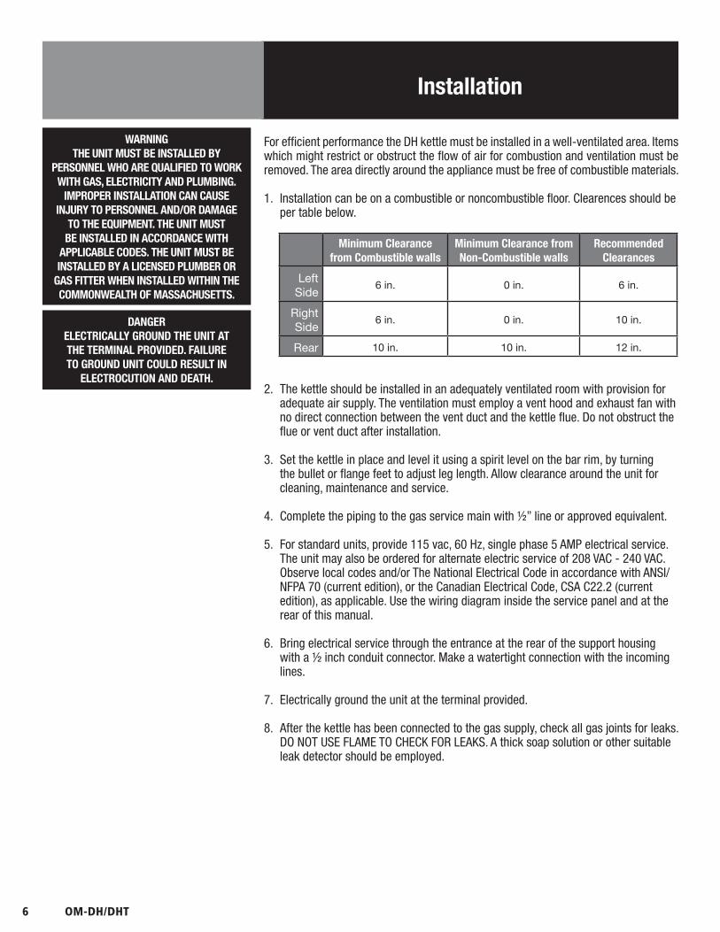
For efficient performance the DH kettle must be installed in a well-ventilated area. Items which might restrict or obstruct the flow of air for combustion and ventilation must be removed. The area directly around the appliance must be free of combustible materials.
1. Installation can be on a combustible or noncombustible floor. Clearences should be per table below.
DANGERELECTRICALLY GROUND THE UNIT AT THE TERMINAL PROVIDED. FAILURE TO GROUND UNIT COULD RESULT IN
ELECTROCUTION AND DEATH.
Installation
WARNINGTHE UNIT MUST BE INSTALLED BY
PERSONNEL WHO ARE QUALIFIED TO WORK WITH GAS, ELECTRICITY AND PLUMBING.
IMPROPER INSTALLATION CAN CAUSE INJURY TO PERSONNEL AND/OR DAMAGE
TO THE EQUIPMENT. THE UNIT MUST BE INSTALLED IN ACCORDANCE WITH
APPLICABLE CODES. THE UNIT MUST BE INSTALLED BY A LICENSED PLUMBER OR
GAS FITTER WHEN INSTALLED WITHIN THE COMMONWEALTH OF MASSACHUSETTS.
Minimum Clearance from Combustible walls
Minimum Clearance from Non-Combustible walls
RecommendedClearances
Left Side 6 in. 0 in. 6 in.
Right Side 6 in. 0 in. 10 in.
Rear 10 in. 10 in. 12 in.
2. The kettle should be installed in an adequately ventilated room with provision for adequate air supply. The ventilation must employ a vent hood and exhaust fan with no direct connection between the vent duct and the kettle flue. Do not obstruct the flue or vent duct after installation.
3. Set the kettle in place and level it using a spirit level on the bar rim, by turning the bullet or flange feet to adjust leg length. Allow clearance around the unit for cleaning, maintenance and service.
4. Complete the piping to the gas service main with ½” line or approved equivalent.
5. For standard units, provide 115 vac, 60 Hz, single phase 5 AMP electrical service. The unit may also be ordered for alternate electric service of 208 VAC - 240 VAC. Observe local codes and/or The National Electrical Code in accordance with ANSI/NFPA 70 (current edition), or the Canadian Electrical Code, CSA C22.2 (current edition), as applicable. Use the wiring diagram inside the service panel and at the rear of this manual.
6. Bring electrical service through the entrance at the rear of the support housing with a ½ inch conduit connector. Make a watertight connection with the incoming lines.
7. Electrically ground the unit at the terminal provided.
8. After the kettle has been connected to the gas supply, check all gas joints for leaks. DO NOT USE FLAME TO CHECK FOR LEAKS. A thick soap solution or other suitable leak detector should be employed.
OM-DH/DHT 7
Installation
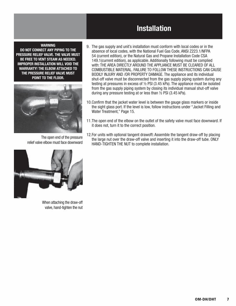
9. The gas supply and unit’s installation must conform with local codes or in the absence of local codes, with the National Fuel Gas Code, ANSI Z223.1/NFPA 54 (current edition), or the Natural Gas and Propane Installation Code CSA 149.1(current edition), as applicable. Additionally following must be complied with: THE AREA DIRECTLY AROUND THE APPLIANCE MUST BE CLEARED OF ALL COMBUSTIBLE MATERIAL. FAILURE TO FOLLOW THESE INSTRUCTIONS CAN CAUSE BODILY INJURY AND /OR PROPERTY DAMAGE. The appliance and its individual shut-off valve must be disconnected from the gas supply piping system during any testing at pressures in excess of ½ PSI (3.45 kPa). The appliance must be isolated from the gas supply piping system by closing its individual manual shut-off valve during any pressure testing at or less than ½ PSI (3.45 kPa).
10. Confirm that the jacket water level is between the gauge glass markers or inside the sight glass port. If the level is low, follow instructions under “Jacket Filling and Water Treatment,” Page 15.
11. The open end of the elbow on the outlet of the safety valve must face downward. If it does not, turn it to the correct position.
12. For units with optional tangent drawoff: Assemble the tangent draw-off by placing the large nut over the draw-off valve and inserting it into the draw-off tube. ONLY HAND-TIGHTEN THE NUT to complete installation.
WARNINGDO NOT CONNECT ANY PIPING TO THE
PRESSURE RELIEF VALVE. THE VALVE MUST BE FREE TO VENT STEAM AS NEEDED.
IMPROPER INSTALLATION WILL VOID THE WARRANTY! THE ELBOW ATTACHED TO
THE PRESSURE RELIEF VALVE MUST POINT TO THE FLOOR.
The open end of the pressure relief valve elbow must face downward
When attaching the draw-off valve, hand-tighten the nut

8 OM-DH/DHT
Initial Start-Up
Now that the kettle has been installed, you should test it to ensure that the unit is operating correctly.
1. Remove literature and packing materials from the interior and exterior of the unit.
2. If the unit is equipped with a draw-off valve (product outlet), clean out any material which might clog or damage the draw-off.
3. Confirm that the tilting mechanism is operating properly by tilting the kettle through its full range. Then return the kettle to the upright position.
4. Turn on the electrical service to the unit.
5. Pour 1-2 gallons of water into the kettle.
6. Following “To Start Kettle” instructions in the “Operation” section (Page 9), begin heating the water at the highest thermostat setting. The heat indicator light should come on, and heating should continue until the water boils.
If the unit functions as described above, it is ready for use. If it does not, contact your local Authorized Service Agency.
WARNINGWATER IS EXTREMELY HOT AND CAN CAUSESEVERE BURNS. AVOID CONTACT WITH HOT
WATER WHEN EMPTYING UNIT.
WARNINGDO NOT STAND ON OR APPLY UNNECESSARY
WEIGHT OR PRESSURE ON THE KETTLE FRONT OR POURING LIP. THIS COULD RESULT
IN THE OVERLOAD AND FAILURE OF THE TILT MECHANISM, AND POSSIBLE SERIOUS INJURY AND BURNS TO
THE OPERATOR AND OTHERS.
Correct water level (Model DH-80E and DHT-80 only)
Each day confirm the jacket water level by checking the water gauge.

OM-DH/DHT 9
Operation
A. Controls Operator controls for the kettle are:
1. Manual gas valve (on gas line behind the unit), which controls the supply of gas from the main to the unit.
2. ON-OFF (Toggle) Switch. This controls the supply of electric power to the control circuits.
3. Thermostat dial, which turns the thermostat on or off, and sets the kettle temperature.
4. Tilting crank, used to tilt the kettle body.
5. Indicator Lights to alert operator of unit conditions:a. POWER Indicator - shows that the unit is turned onb. HEAT Indicator - indicates that main gas is on to produce steam in the
kettle jacket.c. LOW WATER indicator - shows that jacket water is low
6. Unit gas pressure regulator adjustment - located behind the access door in the kettle skirt.
B. Operating Procedure1. To Start Kettle Heating:
a. EVERY DAY make sure that the jacket water level in the middle of the sight glass. If the level is too low, see “Jacket Filling and Water Treatment” on page 15.
b. Check the pressure/vacuum gauge. If the gauge does not show 20 to 30 inches of mercury (Hg) vacuum (that is a reading of 20 to 30 below 0 atmospheric pressure), see “Jacket Vacuum” on page 15.
c. Do not attempt to light any burner with a flame.d. Turn the manual gas valve ON (align handle with gas line).e. Turn toggle (on-off) switch ON. The electronic ignition will attempt to
light the pilot for 90 seconds, or until it is lit. Once lit proceed to step two.
f. Turn thermostat to desired setting. The main gas burner will ignite, and will cycle to maintain the set temperature. The heat indicator light will come on.
g. If the unit does not light, turn it off and wait five minutes. Then follow the instructions again.
2. To Empty Kettle Or To Transfer Product:a. To tilt the body of the kettle forward, turn the hand crank on the front
of the cabinet counter-clockwise. The body will stay in the position it holds when you stop cranking. To return the kettle body to its upright position, turn the crank clockwise.
b. Product may also be transferred by means of the optional draw-off valve, if the kettle is so equipped.
10 OM-DH/DHT
Operation
WARNINGWHEN TILTING KETTLE:
1) WEAR PROTECTIVE OVEN MITT ANDPROTECTIVE APRON.
2) USE DEEP CONTAINER TO CONTAINAND MINIMIZE PRODUCT SPLASHING.
3) PLACE CONTAINER ON STABLE,FLAT SURFACE, AS CLOSE TO
KETTLE AS POSSIBLE.
4) STAND TO RIGHT OF KETTLE WHILEPOURING — NOT DIRECTLY IN POUR
PATH OF HOT CONTENTS.
5) POUR SLOWLY, MAINTAININGCONTROL OF KETTLE, AND RETURN
KETTLE BODY TO UPRIGHT POSITIONAFTER CONTAINER IS FILLED OR
TRANSFER IS COMPLETE.
6) DO NOT OVERFILL CONTAINER.AVOID SKIN CONTACT WITH HOTCONTAINER AND ITS CONTENTS.
WARNINGAVOID ALL DIRECT CONTACT WITH HOTSURFACES AND HOT FOOD OR WATER
IN THE KETTLE. DIRECT CONTACTCOULD RESULT IN SEVERE BURNS.
CAUTIONDO NOT TILT KETTLE WITH LIFT-OFFCOVER IN PLACE. COVER MAY SLIDEOFF, CAUSING INJURY TO OPERATOR.
3. To Stop Kettle Heating:a. Turn thermostat dial to OFF.b. Turn toggle switch to OFF.c. For a prolonged shut-down:
1. Follow the procedure above.2. Turn the manual gas valve off (handle at right angles to gas
line).3. Disconnect electric power from the unit.4. To Relight Kettle
(a) Close main gas supply valve.(b) Set on-off switch to OFF.(c) Set thermostat to OFF.(d) Wait five minutes, then proceed as directed under To Start
Kettle Heating.5. If Power Fails:
(a) Do not attempt to operate the unit until electric power is restored.
(b) When power comes back on, follow directions “To Start Kettle,” above.
C. Use of Common Accessories1. Lift-Off or Counterbalanced Cover: As with stock pot cooking, an optional cover can speed up the heating of
water and food products. It helps retain heat and reduces the heat and humidity in the kitchen. A cover can reduce some product cook times and help maintain the temperature, color and texture of products held or simmered for longer periods.
Be sure the handle is secure on the lift-off cover before using. ALWAYS use the handle to place or remove cover from the kettle. Wear protective oven mitts and apron.
When putting a lift-off cover on the kettle, position it on top of kettle rim, with its flat edge facing the pouring lip.
When removing a lift-off cover:a. Firmly grasp the handle, and lift the rear edge (farthest from operator)
1-2” (3-5 cm) to allow steam and water vapor to escape. Wait 2-3 seconds.
b. Tilt cover to 45-60° angle to allow any hot condensate or product to roll off cover back into kettle.
c. Remove cover, ensuring that remaining hot condensate or product does not drip on operator, floor or work surfaces.
d. Place cover on safe, flat, sanitary, out-of-theway surface, or return to kettle.

OM-DH/DHT 11
Operation
CAUTIONDO NOT OVERFILL THE KETTLE WHEN
COOKING, HOLDING OR CLEANING.KEEP LIQUIDS AT LEAST 2-3” (5-8 cm)
BELOW THE KETTLE RIM TO ALLOWCLEARANCE FOR STIRRING, BOILING
AND SAFE PRODUCT TRANSFER.
WARNINGAVOID ALL DIRECT CONTACT WITH
HOT FOOD OR WATER IN THE KETTLE. DIRECT CONTACT COULD RESULT IN
SEVERE BURNS.
2. Basket Insert: An optional kettle basket insert set (Tri-BC) will assist in cooking water-
boiled products including eggs, potatoes, vegetables, shell fish, pasta and rice. The nylon mesh liner must be used for products smaller than the basket mesh size, (approx. ¼” (6 mm). This includes rice and small pasta shapes.a. Allow for displacement of the three baskets and product. This
may mean only half filling the kettle. Test baskets and product displacement with the kettle OFF, and with cold water in the kettle.
b. Load baskets on a level, stable work surface.c. Lift loaded baskets with both hands. Get help from another person if
the basket is too heavy for safe handling.d. Slowly lower product into kettle and securely hook basket to the “Y”
frame.e. When removing baskets with cooked product, lift straight up, ensuring
basket bottoms clear the kettle rim and pouring lip. Wear protective oven mitts and protective apron.
f. Allow hot water to fully drain from product, before moving basket away from the kettle. Do not rest baskets on kettle rim or pouring lip. If baskets are too heavy for individual to lift and safely move, get help. Remove product immediately from basket into another container, being sure to avoid contact with hot product and hot basket or...
g. Place baskets with food on a stable, flat surface, inside a solid steamer or bake pan, to catch any remaining hot water draining from product.
12 OM-DH/DHT
Sequence of Operation
The following “action-reaction” outline is provided to help understand how the kettle works.
1. When the power switch is turned on, it starts the spark igniter and opens the automatic valve for the pilot burner. The spark ignites a pilot flame, which heats the sensor. The sensor then sends a signal to turn off the spark. The flame thereafter acts as a standing pilot until the power is turned off.
2. If the pilot flame is not sensed within 90 seconds after spark begins, a timer shuts down the entire operation. To attempt a second trial for ignition, turn off the power switch. Check the gas supply valves and wait five minutes before trying again by switching power on. If you cannot establish a pilot flame in four tries, close all valves, turn off the power, and contact an authorized Groen Service Agency.
3. When the operator sets a temperature on the thermostat, it causes the automatic valve to admit gas to the main burner, where it is ignited by the pilot flame. When the kettle reaches the set temperature, the thermostat switch opens. This stops the signal to the gas control valve and shuts off gas to the main burner. The pilot flame remains lit. When the kettle cools below the set temperature, the thermostat switch closes and starts another cycle. On and off cycling continues and maintains the kettle at the desired temperature. This action is indicated by the Heat indicator light.
The kettle has the following safety features in addition to the 90-second ignition timer:
1. Low water cutoff relay that will shut off gas supplies to all burners until the jacket water level is corrected.
2. High limit pressure switch, set to open at about 46 PSI and to shut down the burners until jacket pressure is decreased.
3. Pressure relief valve, which will release steam if jacket pressure exceeds 50 PSI.
4. Tilt switch, which shuts off all burners when the kettle is tilted.
5. Gas pressure regulator built into the gas control valve.

OM-DH/DHT 13
Cleaning
WARNINGKEEP WATER AND SOLUTIONS AWAY FROMCONTROLS AND ELECTRICAL EQUIPMENT.NEVER SPRAY THE SUPPORT HOUSING OR
ELECTRICAL CONNECTIONS.
1. Suggested Cleaning Supplies:a. Cleaner, such as Klenzade HC-10 or HC-32 from ECOLAB, Inc. or equivalent.b. Kettle brushes in good conditionc. Sanitizer such as Klenzade XY-12.d. Film remover such as Klenzade LC-30.
2. Precautions Before cleaning, shut off the kettle by turning the thermostat dial to “OFF,” and
shut off all electric power to the unit at a remote switch, such as the circuit breaker.
3. Procedurea. Clean food-contact surfaces as soon as possible after use. If the unit is in
continuous use, thoroughly clean and sanitize the interior and exterior at least once every 12 hours.
b. Scrape and flush out food residues. Be careful not to scratch the kettle with metal implements. (For DHT models only: After flushing the kettle, close the draw-off valve.)
c. Prepare a hot solution of the detergent/ cleaning compound as instructed by the supplier. Clean the unit thoroughly. A cloth moistened with cleaning solution can be used to clean controls, housings, and electrical conduits.
d. Model DHT only: Disassemble the tangent draw-off valve. Clean the draw-off port and each valve part with a brush.
e. Rinse the kettle and draw-off valve parts thoroughly with hot water, then drain completely.
f. When you reassemble the draw-off valve, hand-tighten the nut which holds it in place.
g. As part of the daily cleaning program, clean soiled external and internal surfaces. Remember to check the sides of the unit and control housing, underside of cover, etc.
h. To remove burnt on foods, use a brush, sponge, cloth, plastic or rubber scraper, or plastic wool with the cleaning solution. To reduce effort required in washing, let the detergent solution sit in the kettle and soak into the resi-due. Do NOT use abrasive materials or metal tools that might scratch the surface. Scratches make the surface harder to clean and provide places for bacteria to grow. Do NOT use steel wool, which may leave particles in the surface and cause eventual corrosion and pitting.
i. The outside of the unit may be polished with a stainless steel cleaner such as “Zepper” from Zep Manufacturing Co.
j. When equipment needs to be sanitized, use a solution equivalent to one that supplies 200 parts per million available chlorine. Obtain advice on sanitizing agents from your supplier of sanitizing products.
k. Following the supplier’s instructions, apply the agent after the unit has been cleaned and drained. Rinse off the sanitizer thoroughly.
l. It is recommended that each piece of equipment be sanitized just before use.m. If there is difficulty removing mineral deposits or a film left by hard water
or food residues, clean the kettle thoroughly and then use a deliming agent, like Groen Delimer/Descaler (Part Number 114800), in accordance with the manufacturer’s directions. Rinse and drain the unit before further use.
n. If cleaning problems persist, contact your cleaning product representative for assistance. The supplier has a trained technical staff with laboratory facilities to serve you.
CAUTIONMOST CLEANERS ARE HARMFUL TO THESKIN, EYES, MUCOUS MEMBRANES, AND
CLOTHING. PRECAUTIONS SHOULD BETAKEN. WEAR RUBBER GLOVES, GOGGLES
OR FACE SHIELD, AND PROTECTIVECLOTHING. READ THE WARNINGS AND
FOLLOW THE DIRECTIONS ON THE LABELOF THE CLEANER CAREFULLY
CAUTIONNEVER LEAVE A SANITIZER IN CONTACT
WITH STAINLESS STEEL SURFACES LONGER THAN 30 MINUTES. LONGER CONTACT CAN CAUSE CORROSION.
CAUTIONDO NOT MIX PARTS OF DIFFERENT DRAWOFF
VALVE ASSEMBLIES. THE PARTS ARENOT INTERCHANGEABLE.
When attaching the draw-off valve, hand-tighten the nut
NOTICENEVER LEAVE A CHLORINE SANITIZER IN
CONTACT WITH STAINLESS STEEL SURFACES LONGER THAN 30 MINUTES. LONGER CONTACT
CAN CAUSE STAINING AND CORROSION.
14 OM-DH/DHT
WARNINGWHEN TESTING, AVOID ANY EXPOSURE TOTHE STEAM BLOWING OUT OF THE SAFETYVALVE. DIRECT CONTACT COULD RESULT IN
SEVERE BURNS.
Maintenance
NOTICE: Contact Groen or an authorized Groen Service Agent when repairs are required.
1. Periodic Maintenance A service Log is provided at the back of this manual with the warranty in-
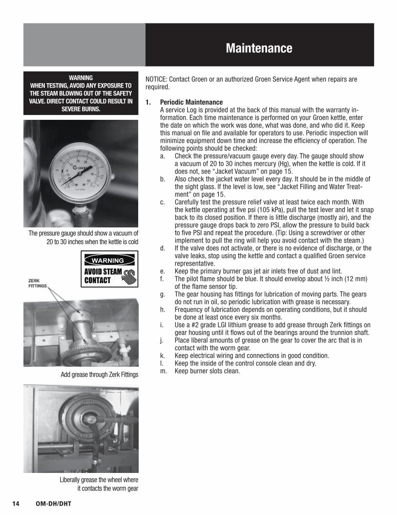
formation. Each time maintenance is performed on your Groen kettle, enter the date on which the work was done, what was done, and who did it. Keep this manual on file and available for operators to use. Periodic inspection will minimize equipment down time and increase the efficiency of operation. The following points should be checked:a. Check the pressure/vacuum gauge every day. The gauge should show
a vacuum of 20 to 30 inches mercury (Hg), when the kettle is cold. If it does not, see “Jacket Vacuum” on page 15.
b. Also check the jacket water level every day. It should be in the middle of the sight glass. If the level is low, see “Jacket Filling and Water Treat-ment” on page 15.
c. Carefully test the pressure relief valve at least twice each month. With the kettle operating at five psi (105 kPa), pull the test lever and let it snap back to its closed position. If there is little discharge (mostly air), and the pressure gauge drops back to zero PSI, allow the pressure to build back to five PSI and repeat the procedure. (Tip: Using a screwdriver or other implement to pull the ring will help you avoid contact with the steam.)
d. If the valve does not activate, or there is no evidence of discharge, or the valve leaks, stop using the kettle and contact a qualified Groen service representative.
e. Keep the primary burner gas jet air inlets free of dust and lint.f. The pilot flame should be blue. It should envelop about ½ inch (12 mm)
of the flame sensor tip.g. The gear housing has fittings for lubrication of moving parts. The gears
do not run in oil, so periodic lubrication with grease is necessary.h. Frequency of lubrication depends on operating conditions, but it should
be done at least once every six months.i. Use a #2 grade LGI lithium grease to add grease through Zerk fittings on
gear housing until it flows out of the bearings around the trunnion shaft.j. Place liberal amounts of grease on the gear to cover the arc that is in
contact with the worm gear.k. Keep electrical wiring and connections in good condition.l. Keep the inside of the control console clean and dry.m. Keep burner slots clean.
The pressure gauge should show a vacuum of 20 to 30 inches when the kettle is cold
Add grease through Zerk Fittings
Liberally grease the wheel where it contacts the worm gear

OM-DH/DHT 15
Maintenance
2. Jacket Vacuum/Removing Air from Jacket When the kettle is cold, a positive pressure reading on the pressure/vacuum
gauge or a reading near zero indicates that there is air in the jacket. Air in the jacket acts as an insulator, and slows kettle heating.
To remove air:a. Start the unit. (Be sure there is water or product in the kettle when heat-
ing).b. When the pressure/vacuum gauge reaches a positive pressure reading of
five PSI, release the trapped air and steam by pulling up the safety valve ring for about five seconds. Repeat this step three or four times. Then let the pull ring snap back into the closed position.
c. If there is little discharge (mostly air), and the pressure gauge drops back to zero PSI, allow the pressure to build back to five PSI and repeat the procedure.
d. Once steam has been vented from the jacket as described in b, above, remove the hot water from the kettle and replace it with cold. This will condense steam in the kettle jacket, and the pressure gauge should show a reading of 20 to 30 inches mercury (Hg) below zero. If it does not, or if the vacuum is leaking down, contact a Groen authorized service agency to correct the problem.
3. Jacket Filling and Water Treatment The jacket was charged at the factory with the proper amount of treated water.
You may need to restore this water, either because it was lost as venting steam or by draining. If you are replacing water lost as steam, use distilled water. If you are replacing treated water that ran out of the jacket, prepare more treated water as directed in “Water Treatment Procedure,” below.a. Allow the kettle to cool completely. The procedure will be easier with the
kettle under vacuum (pressure gauge reading below zero).b. Make sure the fill valve is closed, and remove the square head pipe plug
with open-ended wrench.c. Position a funnel in the opening and fill it with properly treated water.d. Slowly open the fill valve to allow water to be sucked into the jacket.
Quickly close the valve to prevent air from entering.e. Check water level in the jacket to ensure that it is between minimum and
maximum marks on glass or at the top of the sight glass port for models DH/DHT-80 (see photo on page 8).
f. Close the valve and reinstall the squarehead pipe plug.g. Reestablish the jacket vacuum as described in Paragraph 2, above, if
the pressure gauge does not show a negative reading of 20 to 30 inches mercury (Hg).
Safety Valve Pressure Gauge
Test the safety valve at least twice monthly
Check Valve Pipe Plug

16 OM-DH/DHT
WARNINGTO AVOID INJURY, READ AND FOLLOW ALL
PRECAUTIONS ON THE LABEL OF THEWATER TREATMENT COMPOUND.
Maintenance
4. Water Treatment Procedurea. Obtain water treatment compound and a pH test kit from your Groen
Service Agent.b. Fill a mixing container with the measured amount of water required.
Distilled water is recommended. Kettle Model Recommended Jacket Fill DH-20, DHT-20 2-1/2 Gallons DH/1-40, DHT/1-40 3-1/2 Gallons DH-60, DHT-60 4 Gallons DH-80, DHT-80 1-1/4 Gallonsc. Hang a strip of pH test paper on the rim of the container, with about 1
inch of the strip below the surface of the water.d. Measure the water treatment compound. One way to do this is to add the
compound from a measuring cup.e. Stir the water continuously, while you slowly add treatment compound,
until the water has a pH between 10.5 and 11.5. Judge the pH by fre-quently comparing the test strip color with the color chart provided in the test kit. Caution: Do not add excess amount of treatment compound. Excess amount could cause extensive corrosion.
f. As you add water to the jacket, check water level to ensure that it is be-tween minimum and maximum marks on glass or at the top of the sight glass port for models DH/DHT-80 (see photo on page 8). Stop adding water when it reaches the maximum marker on the gauge.
g. Record the exact amounts of water and treatment compound needed. These amounts may be used again, if the same water sources and com-pound are used. However, it is best to check the pH each time treated water is prepared.
5. Component Replacement When component replacement involves breaking a gas pipe connection, check
the new connection with soap solution or an appropriate leak detector. DO NOT USE A FLAME TO TEST FOR LEAKS.
Internal wiring is marked as shown on the circuit schematic drawings (inside control housing and in this manual). Be sure that new components are wired in the same manner as old components. An examination of the circuit schematic shows that the safety components are wired in series. In most cases, a faulty component may be isolated with a jumper wire to verify that the component is faulty. If this determination is made, contact a certified Groen Service Agency for assistance.
WARNINGBEFORE REPLACING ANY PARTS,
DISCONNECT THE UNIT FROM THE ELECTRICPOWER SUPPLY AND CLOSE THE MAIN GAS
VALVE. ALLOW FIVE MINUTES FORUNBURNED GAS TO VENT.

OM-DH/DHT 17
Troubleshooting
Your Groen kettle will operate smoothly and efficiently if properly maintained. However, the following is a list of checks to make in the event of a problem. If the actions suggested do not solve the problem, call your qualified Groen Service Representative. For the phone number of the nearest agency, call your area Groen representative or the Groen Parts and Service Department. If an item on the list is followed by X, the work should only be performed by a qualified service representative.
WARNINGBEFORE REPLACING ANY PARTS, DISCONNECT THE UNIT FROM THE ELECTRICAL POWER SUPPLY AND CLOSE THE MAIN GAS VALVE. ALLOW
FIVE MINUTES FOR GAS TO VENT. USE OF ANY REPLACEMENT PARTS OTHER THAN THOSE SUPPLIED BY THE MANUFACTURER OR THEIR AUTHORIZED DISTRIBUTORS CAN CAUSE INJURY TO THE OPERATOR AND DAMAGE TO THE EQUIPMENT AND WILL VOID ALL WARRANTIES.
SERVICE PERFORMED BY OTHER THAN FACTORY AUTHORIZED PERSONNEL WILL VOID ALL WARRANTIES.
SYMPTOM WHO WHAT TO CHECK X indicates items which must be performed by an authorized technician.
Kettle is hard to tilt. User a. Gears for foreign materials, and lubrication.
Auth Service Rep Only
b. Gears for alignment. Xc. Worm gears or broken gears. X
Kettle continues heating after it reaches the desired temperature.
User a. Thermostat dial setting.
Auth Service Rep Only
b. Thermostat calibration.c. Thermostat operation. The thermostat should click when thedial is rotated above and below the setting for thetemperature of the kettle. X
Kettle stops heating before it reaches the desired temperature.
User a. Thermostat dial setting.
Auth Service Rep Only
b. Thermostat calibration. Xc. Thermostat operation. Thermostat should click when thedial is rotated above and below the setting for thetemperature of the kettle. X
Safety valve pops open. User a. For air in the jacket. See “Jacket Vacuum” in the Maintenance section.b. Thermostat dial setting.
Auth Service Rep Only
c. For defective thermostat. The thermostat should click when the dial is rotated to settings above and below the temperature of the kettle. If defective, replace. Xd. For defective safety valve. If the valve pops at pressures below 49 PSI, replace. X
Burners will not light. User a. That the main gas supply valve is open. (handle is in line with the gas pipe).b. Gas supply to the building.c. That the kettle body is not tilted.
Auth Service Rep Only
d. Thermostat operation. The thermostat should click when the dial is rotated to settings above and below the temperature of the kettle. Xe. That tilt limit switch is closed when body is not tilted.X
System does not produce a spark.
Auth Service Rep Only
a. AC voltage between terminals on secondary side of transformer with unit power turned on. If it is not 24 Volt, replace the transformer. Xb. That the high tension cable is firmly attached and in good condition. If cracked or brittle, replace. Xc. Pilot burner ceramic insulator for crack or break. Xd. Pilot spark gap. Regap. X

18 OM-DH/DHT
Troubleshooting
SYMPTOM WHO WHAT TO CHECK X indicates items which must be performed by an authorized technician.
Spark is present but the pilot will not light.
Auth Service Rep Only
a. That the pilot valve is securely connected to terminals. Xb. For 24 VAC at terminals PV and PV/MV. If 24V is not present, replace the ignition control module. Xb. That gas pressure is at least 3.5” W.C. (8.7818 ub).c. For gas at the pilot. If it is not flowing:(1) Check the pilot gas line for kinks and obstructions. X(2) Clean orifice, if necessary. X(3) Check magnetic operator for pilot valve on gas valve. Repair or replace as necessary. Xd. That the pilot spark gap is located in the pilot gas stream. If not, adjust or replace the pilot burner. Xe. For drafts. Shield the pilot burner, if necessary. X
Pilot lights, but main burner will not come on and spark does not stay on.
Auth Service Rep Only
a. For 24 V between terminals MV and PV/MV while pilot is burning. If24V is not present, replace the ignition control module. Xb. That gas pressure is at least 3.5” W.C.(8.7818 ub). Xc. Electrical connections of the main valve to terminals, to assure that they are securely attached. Check magnetic operator for main valve on gas valve. Repair or replace as necessary. X
Pilot lights, but main burner will not come on, the spark stays on.
Auth Service Rep Only
a. Check for bad burner ground. If necessary, repair with high temperature wire. Xb. Pilot burner ceramic insulator for cracks. Xc. That cable is not grounded out. If it is, correct the ground-out condition or replace cable. Xd. For proper gas pressure. Xe. Clean pilot assembly, or replace if necessary. Xf. Tighten all mechanical and electrical connections. Xg. If the pilot flame is weak, increase pilot orifice size. Xh. Replace ignition control module. X
Main burner comes on but will not stay on.
Auth Service Rep Only
a. Check burner ground for bad wire or connection. Replace if necessary with high temperature wire. Xb. Check for low gas supply pressure. If necessary, replace ignition control module. X
OM-DH/DHT 19
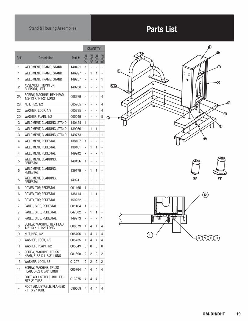
Parts ListStand & Housing Assemblies
QUANTITY
Ref Description Part #
20 G
al
40 G
al
60 G
al
80 G
al
1 WELDMENT, FRAME, STAND 140421 1 - - -
1 WELDMENT, FRAME, STAND 146997 - 1 1 -
1 WELDMENT, FRAME, STAND 149257 - - - 1
2 ASSEMBLY, TRUNNION SUPPORT, LEFT 149258 - - - 1
2A SCREW, MACHINE, HEX HEAD, 1/2-13 X 1-1/2" LONG 008679 - - - 4
2B NUT, HEX, 1/2 005705 - - - 4
2C WASHER, LOCK, 1/2 005735 - - - 4
2D WASHER, PLAIN, 1/2 005049 - - - 8
3 WELDMENT, CLADDING, STAND 140424 1 - - -
3 WELDMENT, CLADDING, STAND 139056 - 1 1 -
3 WELDMENT, CLADDING, STAND 149773 - - - 1
4 WELDMENT, PEDESTAL 138107 1 - - -
4 WELDMENT, PEDESTAL 138101 - 1 1 -
4 WELDMENT, PEDESTAL 149242 - - - 1
5 WELDMENT, CLADDING, PEDESTAL 140426 1 - - -
5 WELDMENT, CLADDING, PEDESTAL 139179 - 1 1 -
5 WELDMENT, CLADDING, PEDESTAL 149241 - - - 1
6 COVER, TOP, PEDESTAL 001465 1 - - -
6 COVER, TOP, PEDESTAL 138114 - 1 1 -
6 COVER, TOP, PEDESTAL 150252 - - - 1
7 PANEL, SIDE, PEDESTAL 001464 1 - - -
7 PANEL, SIDE, PEDESTAL 047882 - 1 1 -
7 PANEL, SIDE, PEDESTAL 149273 - - - 1
8 SCREW, MACHINE, HEX HEAD, 1/2-13 X 1-1/2" LONG 008679 4 4 4 4
9 NUT, HEX, 1/2 005705 4 4 4 4
10 WASHER, LOCK, 1/2 005735 4 4 4 4
11 WASHER, PLAIN, 1/2 005049 8 8 8 8
12 SCREW, MACHINE, TRUSS HEAD, 8-32 X 1-3/8" LONG 081698 2 2 2 2
13 WASHER, LOCK, #8 012971 2 2 2 2
14 SCREW, MACHINE, TRUSS HEAD, 8-32 X 3/8" LONG 005764 4 4 4 4
- FOOT, ADJUSTABLE, BULLET - FITS 2" TUBE 013275 4 4 4 -
- FOOT, ADJUSTABLE, FLANGED - FITS 2" TUBE 096569 4 4 4 4

20 OM-DH/DHT
Parts ListGas Valve, Piping & Bottom Components
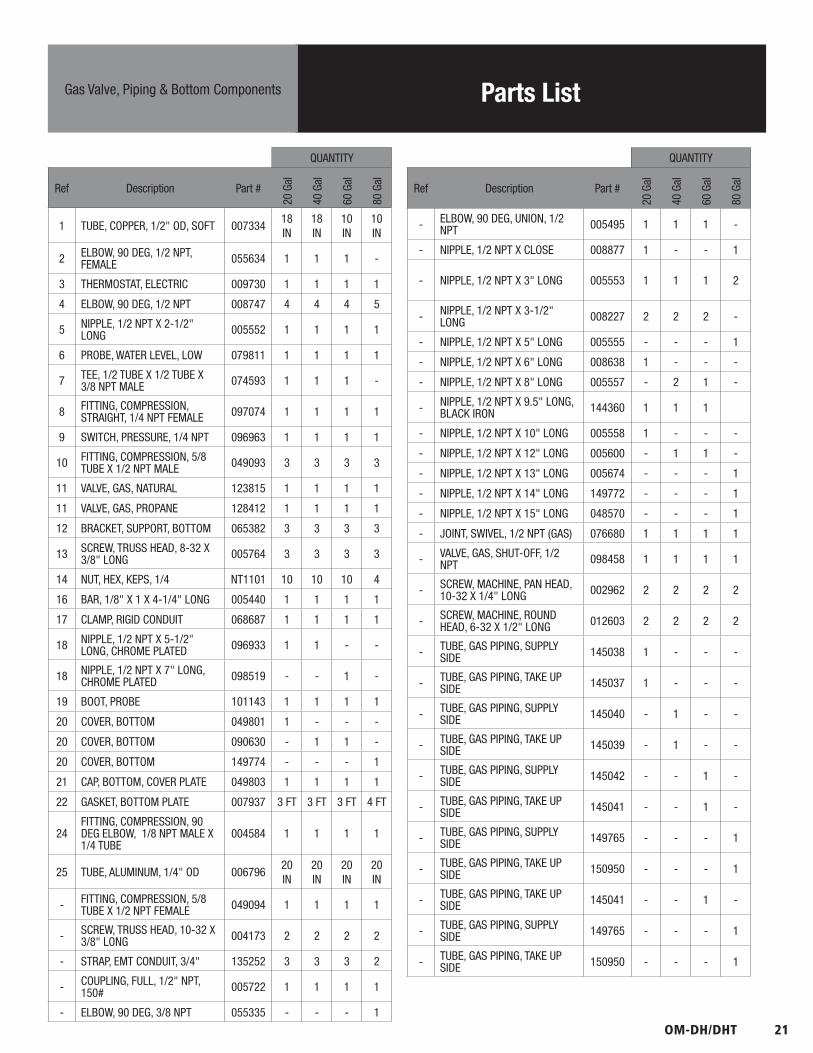
OM-DH/DHT 21
Parts ListGas Valve, Piping & Bottom Components
QUANTITY
Ref Description Part #
20 G
al
40 G
al
60 G
al
80 G
al
1 TUBE, COPPER, 1/2" OD, SOFT 00733418 IN
18 IN
10 IN
10 IN
2 ELBOW, 90 DEG, 1/2 NPT, FEMALE 055634 1 1 1 -
3 THERMOSTAT, ELECTRIC 009730 1 1 1 1
4 ELBOW, 90 DEG, 1/2 NPT 008747 4 4 4 5
5 NIPPLE, 1/2 NPT X 2-1/2" LONG 005552 1 1 1 1
6 PROBE, WATER LEVEL, LOW 079811 1 1 1 1
7 TEE, 1/2 TUBE X 1/2 TUBE X 3/8 NPT MALE 074593 1 1 1 -
8 FITTING, COMPRESSION, STRAIGHT, 1/4 NPT FEMALE 097074 1 1 1 1
9 SWITCH, PRESSURE, 1/4 NPT 096963 1 1 1 1
10 FITTING, COMPRESSION, 5/8 TUBE X 1/2 NPT MALE 049093 3 3 3 3
11 VALVE, GAS, NATURAL 123815 1 1 1 1
11 VALVE, GAS, PROPANE 128412 1 1 1 1
12 BRACKET, SUPPORT, BOTTOM 065382 3 3 3 3
13 SCREW, TRUSS HEAD, 8-32 X 3/8" LONG 005764 3 3 3 3
14 NUT, HEX, KEPS, 1/4 NT1101 10 10 10 4
16 BAR, 1/8" X 1 X 4-1/4" LONG 005440 1 1 1 1
17 CLAMP, RIGID CONDUIT 068687 1 1 1 1
18 NIPPLE, 1/2 NPT X 5-1/2" LONG, CHROME PLATED 096933 1 1 - -
18 NIPPLE, 1/2 NPT X 7" LONG, CHROME PLATED 098519 - - 1 -
19 BOOT, PROBE 101143 1 1 1 1
20 COVER, BOTTOM 049801 1 - - -
20 COVER, BOTTOM 090630 - 1 1 -
20 COVER, BOTTOM 149774 - - - 1
21 CAP, BOTTOM, COVER PLATE 049803 1 1 1 1
22 GASKET, BOTTOM PLATE 007937 3 FT 3 FT 3 FT 4 FT
24FITTING, COMPRESSION, 90 DEG ELBOW, 1/8 NPT MALE X 1/4 TUBE
004584 1 1 1 1
25 TUBE, ALUMINUM, 1/4" OD 00679620 IN
20 IN
20 IN
20 IN
- FITTING, COMPRESSION, 5/8 TUBE X 1/2 NPT FEMALE 049094 1 1 1 1
- SCREW, TRUSS HEAD, 10-32 X 3/8" LONG 004173 2 2 2 2
- STRAP, EMT CONDUIT, 3/4" 135252 3 3 3 2
- COUPLING, FULL, 1/2" NPT, 150# 005722 1 1 1 1
- ELBOW, 90 DEG, 3/8 NPT 055335 - - - 1
QUANTITY
Ref Description Part #
20 G
al
40 G
al
60 G
al
80 G
al
- ELBOW, 90 DEG, UNION, 1/2 NPT 005495 1 1 1 -
- NIPPLE, 1/2 NPT X CLOSE 008877 1 - - 1
- NIPPLE, 1/2 NPT X 3" LONG 005553 1 1 1 2
- NIPPLE, 1/2 NPT X 3-1/2" LONG 008227 2 2 2 -
- NIPPLE, 1/2 NPT X 5" LONG 005555 - - - 1
- NIPPLE, 1/2 NPT X 6" LONG 008638 1 - - -
- NIPPLE, 1/2 NPT X 8" LONG 005557 - 2 1 -
- NIPPLE, 1/2 NPT X 9.5" LONG, BLACK IRON 144360 1 1 1
- NIPPLE, 1/2 NPT X 10" LONG 005558 1 - - -
- NIPPLE, 1/2 NPT X 12" LONG 005600 - 1 1 -
- NIPPLE, 1/2 NPT X 13" LONG 005674 - - - 1
- NIPPLE, 1/2 NPT X 14" LONG 149772 - - - 1
- NIPPLE, 1/2 NPT X 15" LONG 048570 - - - 1
- JOINT, SWIVEL, 1/2 NPT (GAS) 076680 1 1 1 1
- VALVE, GAS, SHUT-OFF, 1/2 NPT 098458 1 1 1 1
- SCREW, MACHINE, PAN HEAD, 10-32 X 1/4" LONG 002962 2 2 2 2
- SCREW, MACHINE, ROUND HEAD, 6-32 X 1/2" LONG 012603 2 2 2 2
- TUBE, GAS PIPING, SUPPLY SIDE 145038 1 - - -
- TUBE, GAS PIPING, TAKE UP SIDE 145037 1 - - -
- TUBE, GAS PIPING, SUPPLY SIDE 145040 - 1 - -
- TUBE, GAS PIPING, TAKE UP SIDE 145039 - 1 - -
- TUBE, GAS PIPING, SUPPLY SIDE 145042 - - 1 -
- TUBE, GAS PIPING, TAKE UP SIDE 145041 - - 1 -
- TUBE, GAS PIPING, SUPPLY SIDE 149765 - - - 1
- TUBE, GAS PIPING, TAKE UP SIDE 150950 - - - 1
- TUBE, GAS PIPING, TAKE UP SIDE 145041 - - 1 -
- TUBE, GAS PIPING, SUPPLY SIDE 149765 - - - 1
- TUBE, GAS PIPING, TAKE UP SIDE 150950 - - - 1

22 OM-DH/DHT
Parts ListModule Box
Ref Description Part # Qty
1 NUT, LOCK, 1/2, CONDUIT 005487 1
2SCREW, TRUSS HEAD, 8-32 X 3/8" LONG
005764 6
3 MODULE BOX 123775 1
4 GASKET, MODULE BOX 104941 1
5 MODULE, IGNITION 085153 1
6 NUT, HEX, KEPS, 6-32 071289 2
7ADAPTER, CONDUIT, PLASTIC, MALE
123733 1
8 COVER, MODULE BOX 104948 1
9 NUT, HEX, KEPS, 8-32 069784 1
10ANCHOR, CABLE TIE, SCREW-MOUNTED
102231 1
11 STRAP, CABLE TIE 011093 1
12CABLE. HI VOLTAGE, SPARK IGNITION
096728 1
-SCREW, HEX BINDER HEAD, 10-32 X 3/8" LONG
084201 2

OM-DH/DHT 23
Parts ListBurner & Pilot/Flame Sensor Components
QUANTITY
Ref Description Part #
20 G
al
40 G
al
60 G
al
80 G
al
1 BAFFLE PLATE 123496 1 - - -
1 BAFFLE PLATE 123497 - 1 - -
1 BAFFLE PLATE 123498 - - 1 1
2 NUT, HEX,SERRATED, 1/4-20 NT1101 8 8 8 8
3 PILOT BURNER, NAT GAS 123580 1 1 1 1
3 PILOT BURNER, PROPANE 128415 1 1 1 1
4 BRACKET, BURNER SUPPORT 117008 2 - - -
4 BRACKET, BURNER SUPPORT 117009 - 2 - -
4 BRACKET, BURNER SUPPORT 117010 - - 2 2
5 BRACKET, BURNER 117011 2 - - -
5 BRACKET, BURNER 117012 - 2 - -
5 BRACKET, BURNER 117013 - - 2 2
- WASHER, FENDER, 1/4 132107 - - 3 3
6 BURNER MANIFOLD AND ORIFICES NOTE 1 1 1 1 1
NOTE
1 CONTACT FACTORY WITH ELEVATION AND GAS TYPE (NATURAL, PROPANE, OR SPECIAL MIX) TO OBTAIN CORRECTMANIFOLD AND ORIFICES.

24 OM-DH/DHT
Parts ListFlue Stack
QUANTITY
Ref Description Part # 20 Gal 40 Gal 60 Gal 80 Gal
1FLUE, MAIN BODY & FRONT SECTION
117035117036 1 - - -
1FLUE, MAIN BODY & FRONT SECTION
117031117032 - 1 - -
1FLUE, MAIN BODY & FRONT SECTION
137874137872 - - 1 -
1FLUE, MAIN BODY & FRONT SECTION
149220150927 - - - 1
2 FLUE, TOP PLATE, TOP SECTION 117038 1 - - -
2 FLUE, TOP PLATE, TOP SECTION 117029 - 1 - -
2 FLUE, TOP PLATE, TOP SECTION 128169 - - 1 -
2 FLUE, TOP PLATE, TOP SECTION 149222 - - - 1
3FLUE, TOP PLATE, BOTTOM SECTION
117037 1 - - -
3FLUE, TOP PLATE, BOTTOM SECTION
117033 - 1 - -
3FLUE, TOP PLATE, BOTTOM SECTION
117028 - - 1 -
3FLUE, TOP PLATE, BOTTOM SECTION
149236 - - - 1
4SCREW, TRUSS HEAD, 10-32 X 1/2 LONG
072189 6 6 8 8
OM-DH/DHT 25
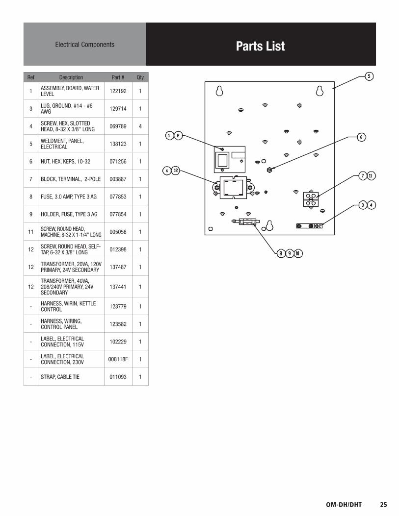
Parts ListElectrical Components
Ref Description Part # Qty
1 ASSEMBLY, BOARD, WATER LEVEL 122192 1
3 LUG, GROUND, #14 - #6 AWG 129714 1
4 SCREW, HEX, SLOTTED HEAD, 8-32 X 3/8" LONG 069789 4
5 WELDMENT, PANEL, ELECTRICAL 138123 1
6 NUT, HEX, KEPS, 10-32 071256 1
7 BLOCK, TERMINAL, 2-POLE 003887 1
8 FUSE, 3.0 AMP, TYPE 3 AG 077853 1
9 HOLDER, FUSE, TYPE 3 AG 077854 1
11 SCREW, ROUND HEAD, MACHINE, 8-32 X 1-1/4" LONG 005056 1
12 SCREW, ROUND HEAD, SELF-TAP, 6-32 X 3/8" LONG 012398 1
12 TRANSFORMER, 20VA, 120V PRIMARY, 24V SECONDARY 137487 1
12TRANSFORMER, 40VA, 208/240V PRIMARY, 24V SECONDARY
137441 1
- HARNESS, WIRIN, KETTLE CONTROL 123779 1
- HARNESS, WIRING, CONTROL PANEL 123582 1
- LABEL, ELECTRICAL CONNECTION, 115V 102229 1
- LABEL, ELECTRICAL CONNECTION, 230V 008118F 1
- STRAP, CABLE TIE 011093 1

26 OM-DH/DHT
Parts ListFront Panel Components
QUANTITY
Ref Description Part #
20 G
al
40 G
al
60 G
al
80 G
al
1 LIGHT, INDICATOR, RED, 24VAC 116383 1 1 1 1
2 LIGHT, INDICATOR, AMBER, 24VAC 116384 2 2 2 2
3 SWITCH, SPST, ON/OFF 006904 1 1 1 1
- OVERLAY, DH CONTROLS 123802 1 1 1 -
- OVERLAY, UPPER, DH-80 150237 - - - 1
- OVERLAY, LOWER, DH-80 150238 - - - 1
- KNOB, THERMOSTAT 012314 1 1 1 1
OM-DH/DHT 27
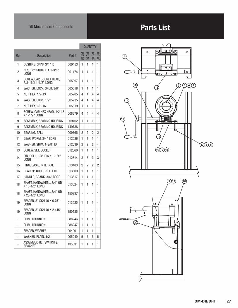
Parts ListTilt Mechanism Components
QUANTITY
Ref Description Part #
20 G
al
40 G
al
60 G
al
80 G
al
1 BUSHING, SNAP, 3/4" ID 000453 1 1 1 1
2 KEY, 3/8" SQUARE X 1-3/8" LONG 001474 1 1 1 1
3 SCREW, CAP, SOCKET HEAD, 3/8-16 X 1-1/2" LONG 005097 1 1 1 1
4 WASHER, LOCK, SPLIT, 3/8" 005618 1 1 1 1
5 NUT, HEX, 1/2-13 005705 4 4 4 4
6 WASHER, LOCK, 1/2" 005735 4 4 4 4
7 NUT, HEX, 3/8-16 005619 1 1 1 1
8 SCREW, CAP, HEX HEAD, 1/2-13 X 1-1/2" LONG 008679 4 4 4 4
9 ASSEMBLY, BEARING HOUSING 009762 1 1 1 -
9 ASSEMBLY, BEARING HOUSING 149788 - - - 1
10 BEARING, BALL 009765 2 2 2 2
11 GEAR, WORM, 3/4" BORE 012026 1 1 1 1
12 WASHER, SHIM, 1-3/8" ID 012039 2 2 2 -
13 SCREW, SET, SOCKET 012060 1 1 1 1
14 PIN, ROLL, 1/4" DIA X 1-1/4" LONG 012614 3 3 3 3
15 RING, BASIC, INTERNAL 013483 2 2 2 2
16 GEAR, 3" BORE, 92 TEETH 013609 1 1 1 1
17 HANDLE, CRANK, 3/4" BORE 013617 1 1 1 1
18 SHAFT, HANDWHEEL, 3/4" OD X 13-1/2" LONG 013624 1 1 1 -
18 SHAFT, HANDWHEEL, 3/4" OD X 20-1/2" LONG 150937 - - - 1
19 SPACER, 3" SCH 40 X 0.75" LONG 013625 1 1 1 -
19 SPACER, 3" SCH 40 X 2.445" LONG 150235 - - - 1
- SHIM, TRUNNION 088246 1 1 1 -
- SHIM, TRUNNION 088247 1 1 1 -
- SPACER, WASHER 004901 1 1 1 1
- WASHER, PLAIN, 1/2" 005049 5 5 5 5
- ASSEMBLY, TILT SWITCH & BRACKET 135331 1 1 1 1

28 OM-DH/DHT
Parts ListWater Level & Safety Valve Components
QUANTITY
Ref Description Part #
20 G
al
40 G
al
60 G
al
80 G
al
1 ASSEMBLY, WATER FILL 097007 1 1 1 -
2 VALVE, SAFETY, 1/2 NPT, 50 PSI 097005 1 1 1 1
3 ELBOW, 90 DEG, 1/2 NPT, CHROME PLATED 010108 1 1 1 -
- ASSEMBLY, PLATE & CHAIN 008332 1 1 1 -
4 COUPLING, FULL, 1/2 NPT, (NICKEL PLATED) 149048 2 2 2 1
5 ELBOW, 90 DEG, STREET, 1/2 NPT 096905 - - - 1
6 GAUGE, COMPOUND PRESSURE, W/DUAL SCALE 084208 1 1 1 1
7 NIPPLE, CLOSE, 1/2" NPT 008877 1 1 1 1
8 ASSEMBLY, PIPING, RELIEF VALVE 141428 - - - 1
9 ASSEMBLY, PIPING, WATER-FILL 139396 - - - 1
- SIGHT GLASS, 1-1/4 NPT 108554 - - - 1
10 FITTINGS, SIGHT GLASS 002845 1 1 1 -
11 GLASS, WATER LEVEL 008742 1 1 - -
11 GLASS, WATER LEVEL 009752 - - 1 -
12 GROMMET, 7/8" ID 007400 2 2 2 -
13 ROD, GUARD, GLASS 002981 2 2 - -
13 ROD, GUARD, GLASS 003127 - - 2 -
- LABEL, MAXIMUM & MINIMUM 000558 1 1 1 -
14 NUT, HEX, CAP, 10-24 005470 2 2 2 -

OM-DH/DHT 29
Parts ListReplacement Kettle Body Assemblies
QUANTITY
Description Part #
20 G
al
40 G
al
60 G
al
80 G
al
REPLACEMENT KETTLE BODY ASSEMBLIES
KBA & TRUNNION DH-20 50PSI 117057 1 - - -
KBA & TRUNNION DHT-20 2" TDO 50 PSI 117059 1 - - -
KBA & TRUNNION DH-40 50 PSI 117066 - 1 - -
KBA & TRUNNION DHT-40 2" TDO 50 PSI 117062 - 1 - -
KBA & TRUNNION DH-60 50 PSI 117068 - - 1 -
KBA & TRUNNION DHT-60 2" TDO 50 PSI 117065 - - 1 -
KBA & TRUNNION, DH-80 50 PSI 150960 - - - 1
KBA & TRUNNION DHT-80 2" TDO 50 PSI 149783 - - - 1
REPLACEMENT COMBUSTION CHAMBERS
CHAMBER, COMBUSTION 122092 1 - - -
CHAMBER, COMBUSTION 122093 - 1 - -
DIVERTER, FLUE GAS 062105 - 2 - -
DIVERTER, FLUE GAS 062106 - 2 - -
CHAMBER, COMBUSTION 122094 - - 1 -
DIVERTER, CENTER PLATE, FLUE GAS 049716 - - 2 -
DIVERTER, CENTER PLATE, FLUE GAS 049718 - - 2 2
DIVERTER, SIDE PLATE, FLUE GAS 049717 - - 2 2
CHAMBER, COMBUSTION 122094 - - - 1
DIVERTER, TOP PLATE 154028 - - - 1
REPLACEMENT 2" TDO VALVE COMPONENTS
HANDLE, BLACK, 3" DIA 009029 1 1 1 1
NUT, WING, 10-24 009028 1 1 1 1
STEM, VALVE, W/COMPRESSION DISK 009048 1 1 1 1
O-RING, 7/16" ID 009034 1 1 1 1
BONNET, VALVE 009047 1 1 1 1
NUT, HEX 009354 1 1 1 1
30 OM-DH/DHT
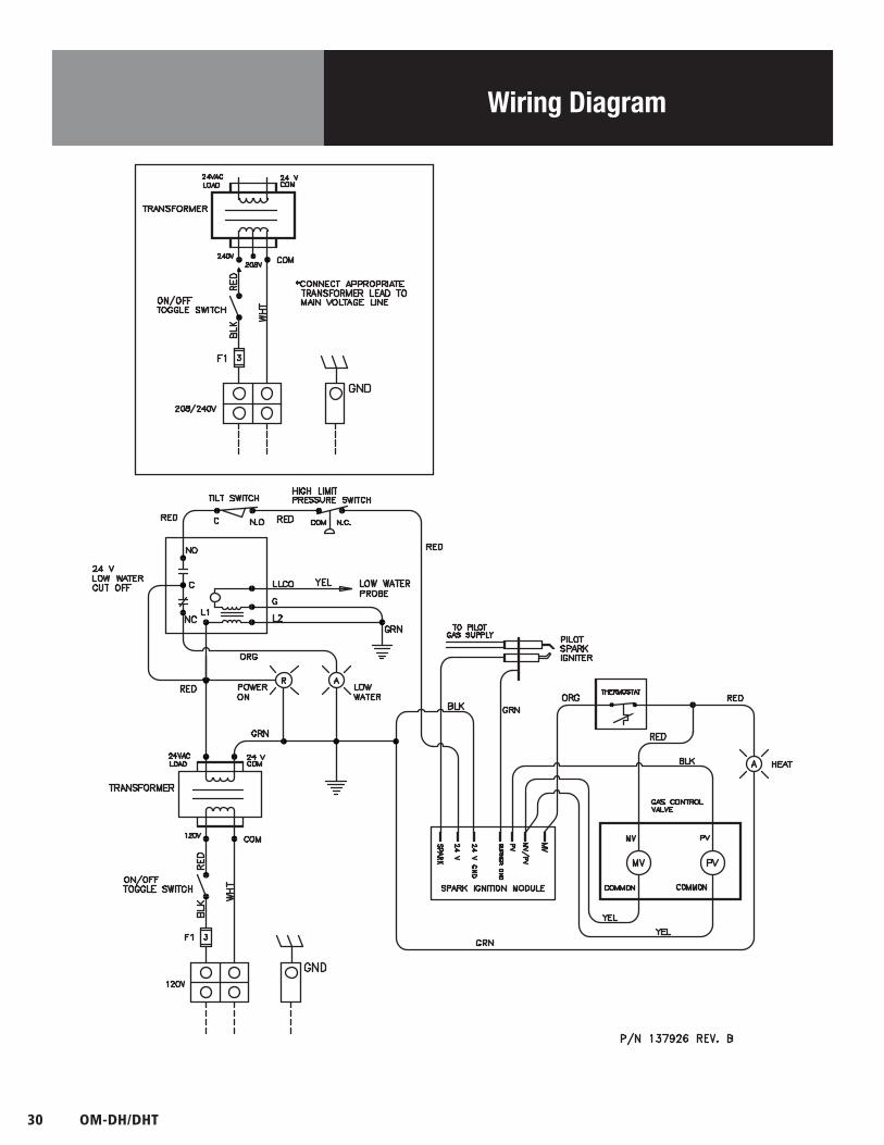
Wiring Diagram
OM-DH/DHT 31
Service Log
Model No: Purchased From:
Serial No: Location:
Date Purchased: Date Installed:
Purchase Order No: For Service Call:
Date Maintenance Performed Performed By

PART NUMBER 121050, REV. K (07/15)
1055 Mendell Davis Drive • Jackson MS 39272888-994-7636 • 601-372-3903 • Fax 888-864-7636
unifiedbrands.net
© 2015 Unified Brands. All Rights Reserved. Unified Brands is a wholly-owned subsidiary of Dover Corporation.


![A Torrent Recommender based on DHT Crawling · torrents. 1.1 Related Work DHT crawling has previously been done for the Vuze DHT by Scott Wolchok [2]. Wolchok’s approach shows that](https://img.pdfslide.us/doc/110x75/5f7551b3b54fc4780247d72e/a-torrent-recommender-based-on-dht-crawling-torrents-11-related-work-dht-crawling.jpg)


![DH Slide Deck v4.ppt [Read-Only]](https://img.pdfslide.us/doc/110x75/613d4584736caf36b75b5b8c/dh-slide-deck-v4ppt-read-only.jpg)